JP6609536B2 - Integrated lens mount - Google Patents
Integrated lens mount Download PDFInfo
- Publication number
- JP6609536B2 JP6609536B2 JP2016183765A JP2016183765A JP6609536B2 JP 6609536 B2 JP6609536 B2 JP 6609536B2 JP 2016183765 A JP2016183765 A JP 2016183765A JP 2016183765 A JP2016183765 A JP 2016183765A JP 6609536 B2 JP6609536 B2 JP 6609536B2
- Authority
- JP
- Japan
- Prior art keywords
- mount
- ring
- radial
- connecting web
- axial
- Prior art date
- Legal status (The legal status is an assumption and is not a legal conclusion. Google has not performed a legal analysis and makes no representation as to the accuracy of the status listed.)
- Active
Links
- 238000005452 bending Methods 0.000 claims description 27
- 230000007704 transition Effects 0.000 claims description 17
- 239000000463 material Substances 0.000 claims description 14
- 230000003796 beauty Effects 0.000 claims 2
- 239000000523 sample Substances 0.000 claims 1
- 230000035882 stress Effects 0.000 description 22
- 230000003287 optical effect Effects 0.000 description 16
- 238000006243 chemical reaction Methods 0.000 description 8
- 230000005540 biological transmission Effects 0.000 description 4
- 239000010409 thin film Substances 0.000 description 4
- 238000010276 construction Methods 0.000 description 3
- 230000000694 effects Effects 0.000 description 3
- 230000002787 reinforcement Effects 0.000 description 3
- 230000008646 thermal stress Effects 0.000 description 3
- 238000010521 absorption reaction Methods 0.000 description 2
- 238000003384 imaging method Methods 0.000 description 2
- 238000013001 point bending Methods 0.000 description 2
- 239000000853 adhesive Substances 0.000 description 1
- 230000001070 adhesive effect Effects 0.000 description 1
- 230000008878 coupling Effects 0.000 description 1
- 238000010168 coupling process Methods 0.000 description 1
- 238000005859 coupling reaction Methods 0.000 description 1
- 238000010438 heat treatment Methods 0.000 description 1
- 238000009434 installation Methods 0.000 description 1
- 238000004519 manufacturing process Methods 0.000 description 1
- 230000028161 membrane depolarization Effects 0.000 description 1
- 230000002093 peripheral effect Effects 0.000 description 1
- 230000005855 radiation Effects 0.000 description 1
- 238000004513 sizing Methods 0.000 description 1
- 125000006850 spacer group Chemical group 0.000 description 1
- 239000003351 stiffener Substances 0.000 description 1
Images


Classifications
-
- G—PHYSICS
- G02—OPTICS
- G02B—OPTICAL ELEMENTS, SYSTEMS OR APPARATUS
- G02B7/00—Mountings, adjusting means, or light-tight connections, for optical elements
- G02B7/02—Mountings, adjusting means, or light-tight connections, for optical elements for lenses
- G02B7/021—Mountings, adjusting means, or light-tight connections, for optical elements for lenses for more than one lens
-
- G—PHYSICS
- G02—OPTICS
- G02B—OPTICAL ELEMENTS, SYSTEMS OR APPARATUS
- G02B7/00—Mountings, adjusting means, or light-tight connections, for optical elements
- G02B7/02—Mountings, adjusting means, or light-tight connections, for optical elements for lenses
- G02B7/026—Mountings, adjusting means, or light-tight connections, for optical elements for lenses using retaining rings or springs
-
- G—PHYSICS
- G02—OPTICS
- G02B—OPTICAL ELEMENTS, SYSTEMS OR APPARATUS
- G02B1/00—Optical elements characterised by the material of which they are made; Optical coatings for optical elements
- G02B1/04—Optical elements characterised by the material of which they are made; Optical coatings for optical elements made of organic materials, e.g. plastics
- G02B1/041—Lenses
Description
レンズマウントは基本的に、接合群(cemented groups)とも呼ばれる互いに結合された複数のレンズ又は個々の光学レンズ(以下では単にレンズと呼ぶ)を、レンズ装置内で正確に設置された及び/又は調節された位置に、すなわち、互いに対する所定の間隔及び向きで正確に保持するために使用される。これ以外に、特に非常に低い波面変形及び減極を特徴とする、結像品質のための高い要件を有するレンズ装置にとって、レンズが、環境に対して安定するように及び可能な限り変形が無く残留応力の無いように設けられることと、搭載レンズが高い固有周波数を有することが重要である。 A lens mount basically consists of a plurality of coupled lenses or individual optical lenses (hereinafter simply referred to as lenses), also called cemented groups, precisely placed and / or adjusted in a lens arrangement. Used to hold precisely in a given position, i.e. at a predetermined spacing and orientation relative to each other. Apart from this, for lens devices with a high requirement for imaging quality, especially characterized by very low wavefront deformation and depolarization, the lens is stable to the environment and as deformation-free as possible. It is important that the lens is provided with no residual stress and that the mounted lens has a high natural frequency.
レンズマウントで生じる応力、従って搭載レンズに作用する力には多数の異なる理由がある。 There are a number of different reasons for the stress generated in the lens mount, and hence the force acting on the mounted lens.
以下で述べる3つの原因が、レンズマウントにおいて又はレンズマウントとレンズの間に個々に又は同時に応力を生じさせる主な原因である。 The three causes described below are the main causes of stress in the lens mount or between the lens mount and the lens individually or simultaneously.
1つの理由は、マウントの及び光学素子の材料の異なる膨張率により生じる熱応力を利用しなければならないことである。周囲温度の変動の結果又は特に放射線が当たったときにレンズが加熱されたときに、熱応力は生じる。半径方向に搭載されたレンズの場合、生じる熱応力は、実質的にレンズへのラジアル力の導入によってレンズに作用する。 One reason is that thermal stresses caused by different expansion rates of the mount and optical element materials must be utilized. Thermal stresses occur as a result of ambient temperature fluctuations or when the lens is heated, particularly when exposed to radiation. In the case of a radially mounted lens, the resulting thermal stress acts on the lens by the introduction of a radial force on the lens substantially.
応力の別の理由は調節ユニットの作動であろう。調節ユニットの作動により、レンズマウントが内側マウントリングと外側マウントリングに分けられるときに、レンズが保持された内側マウントリングが外側マウントリングに対して調節される。この場合にも、実質的に半径方向に働く力(以下では、ラジアル力)又は少なくともラジアル平面に働く力がレンズに導入される。 Another reason for the stress may be the operation of the adjustment unit. When the lens mount is divided into the inner mount ring and the outer mount ring by the operation of the adjusting unit, the inner mount ring holding the lens is adjusted with respect to the outer mount ring. In this case as well, a force acting in a substantially radial direction (hereinafter radial force) or at least a force acting in the radial plane is introduced into the lens.
熱誘起された力はレンズマウントの対称軸に対して対称的に作用するが、調節ユニットの作動により生じる力は逐一、非対称に作用する。 Although the heat-induced force acts symmetrically with respect to the axis of symmetry of the lens mount, the force generated by the operation of the adjusting unit acts asymmetrically.
第3の理由は、個々のレンズマウントを互いに接続する点にある。この種の接続は、例えば、同じ外径を有するレンズマウントが対物レンズ鏡筒に連続的に挿入され、全面取付ねじリングによって固定されることで創出できる。この種の接続はまた、レンズマウントが例えばねじにより互いに接続されることでも創出される。高い保持力のために、マイクロメートル範囲の平面度の偏差でさえ、レンズマウントの著しい変形をもたらす。この変形が全部レンズに伝わった場合、ある程度の変形をもたらし、又はレンズの結像品質を許容できないほど悪化させる応力がレンズに導入されることになる。 The third reason is that individual lens mounts are connected to each other. This type of connection can be created, for example, by continuously inserting lens mounts having the same outer diameter into the objective lens barrel and fixing them with the entire surface mounting screw ring. This type of connection is also created when the lens mounts are connected to each other, for example by screws. Due to the high holding force, even flatness deviations in the micrometer range result in significant deformation of the lens mount. If all of this deformation is transmitted to the lens, stress will be introduced into the lens that will cause some deformation, or unacceptably deteriorate the imaging quality of the lens.
レンズが互いに接続される方法にかかわらず、2つの隣接して配置されたレンズマウントの端面は互いに直接又は調節リングを介して接触する。レンズマウント及び/又は調節リング(使用される場合)の端面のいかなる凸凹も、原則として、レンズマウントの捩れをもたらし、それゆえレンズに働く、半径方向及び軸方向に作用する力をもたらす。この捩れは、ねじによる接続の場合にはねじでの締め付けトルクを異ならせることによっても生じる。 Regardless of how the lenses are connected to each other, the end faces of two adjacent lens mounts contact each other directly or via an adjustment ring. Any irregularities in the end face of the lens mount and / or the adjustment ring (if used) will in principle lead to a twist of the lens mount and hence a radially and axially acting force acting on the lens. This twist is also caused by different tightening torques in the case of connection by screws.
従来技術では、前述した様々な応力がレンズマウントに保持されたレンズに伝わることをできるだけ防ぐために、多様な手段が講じられる。これら手段は、レンズマウントの材料、寸法決め及び/又は構造設計の選択にある。 In the prior art, various measures are taken to prevent the various stresses described above from being transmitted to the lens held in the lens mount as much as possible. These means are in the choice of lens mount material, sizing and / or structural design.
構成に関して、レンズの変形を少なくとも軽減する最も簡単な方法は、レンズマウントがレンズと連絡するために介する接触表面の実質的な変形が無いように、外側マウントリングと内側マウントリングに分けられたマウントの内側マウントリングを非常に強固に構成することである。しかしながら、これは、小さい取り付けスペース、材料の経済的な使用及び軽量構造に対する要求と相反し、非常に過度に要求する要件のために技術的に不可能である。 In terms of construction, the simplest way to at least reduce lens deformation is to mount the outer mount ring and inner mount ring so that there is no substantial deformation of the contact surface through which the lens mount communicates with the lens. The inner mounting ring of the is constructed very firmly. However, this is technically impossible due to requirements that are very overly demanding, contrary to the requirements for small mounting space, economical use of materials and lightweight construction.
特に外側マウントリングに作用する力又はモーメントが内側マウントリングに伝達するのを防止するために、外側マウントリングと内側マウントリングが互いに接続されるときに介する接続構造を設計することがより一般的である。 It is more common to design a connection structure through which the outer mount ring and the inner mount ring are connected to each other, particularly to prevent forces or moments acting on the outer mount ring from being transmitted to the inner mount ring. is there.
特に、内側マウントリングに伝達される力を吸収してこれらの力をレンズに伝達させないために、レンズを保持するマウントリングであって、内側マウントリングであってもよいマウントリングを設計することも公知である。このために、例えば特許文献1から公知のレンズマウントでは、レンズに形成された環状溝に半径方向に延在するレンズマウントに、弾性セグメントが形成される。
In particular, in order to absorb the forces transmitted to the inner mount ring and not transmit these forces to the lens, it is also possible to design a mount ring that holds the lens and may be the inner mount ring. It is known. For this purpose, for example, in a lens mount known from
上に列挙した3つの基本的に異なる手段、すなわち、レンズとの接触領域での 変形を防ぐための強固な構成、接続構造による力の吸収及びレンズを直接保持するマウントリングによる力の吸収は、応力から分離するようにレンズをレンズマウントに保持するために、個々に又は組み合わせて講じることができる。 The three fundamentally different means listed above, namely the robust construction to prevent deformation in the contact area with the lens, the absorption of force by the connection structure and the absorption of force by the mounting ring that holds the lens directly, In order to keep the lens in the lens mount so as to separate from the stress, it can be taken individually or in combination.
本明細書の意味において「応力から分離される」又は「変形から分離される」は、外側マウントリングにて生じた応力が内側マウントリングに実際に全く伝達しないことを意味せず、むしろ応力がせいぜい僅かに伝達されることを意味する。 In the sense of the present specification, “separated from stress” or “separated from deformation” does not mean that the stress generated in the outer mounting ring is actually not transmitted to the inner mounting ring at all, rather the stress is It means that it is transmitted at most.
説明したように、外側マウントリングで生じる応力の前述した原因は、主に、半径方向軸と垂直な軸、又はそれぞれの接続構造を通って延びる仮想半径方向軸の伸長と垂直な軸(以下では接続軸)の周りの接続構造の屈曲をもたらすアクティブな力である。他方で、接続軸の周りに作用する捩りモーメントは接続構造に捩れを生じさせる。生じる全ての効果、組み合わせで生じる効果に関してさえ、接続構造は、レンズマウントの、それゆえ接続構造の引張剛性、曲げ剛性及び捩り剛性に依存して様々な程度で接続構造を介して伝達される力を受ける。 As explained, the aforementioned causes of the stresses generated in the outer mounting ring are mainly due to the axis perpendicular to the radial axis or the extension of the virtual radial axis extending through the respective connecting structure (hereinafter referred to as It is an active force that causes the connection structure to bend around the connection axis. On the other hand, the torsional moment acting around the connecting shaft causes the connecting structure to twist. For all the effects that occur, even for the effects that occur in combination, the connection structure is a force that is transmitted through the connection structure to varying degrees, depending on the lens mount and hence the tensile, bending and torsional stiffness of the connection structure. Receive.
この点について、引張剛性は半径方向軸に沿う剛性を特徴とし、曲げ剛性は半径方向軸と垂直な軸に沿う剛性を特徴とし、捩り剛性は半径方向軸の周りの剛性を特徴とする。 In this regard, tensile stiffness is characterized by stiffness along the radial axis, bending stiffness is characterized by stiffness along an axis perpendicular to the radial axis, and torsional stiffness is characterized by stiffness around the radial axis.
応力から分離されるように内側マウントリングを外側マウントリングに接続する接続構造は、予期される力又は捩りモーメントにより外側マウントリングに導入される応力をせいぜい僅かな程度内側マウントリングに伝達する接続構造を意味する。 The connection structure that connects the inner mounting ring to the outer mounting ring so as to be separated from the stress is a connection structure that transmits the stress introduced to the outer mounting ring by an expected force or torsional moment to the inner mounting ring to a minimum degree. Means.
特許文献2から公知のマウント装置は、レンズ又は他の光学素子を保持するマウントリングとして機能する、又は異なる直径のマウントリングを適合させるためのスペーサーリング又は適合リングとして機能する多数の光学リングを有している。これら光学リングの端面が、リングにねじ留めするために設けられた穴の周りの表面処理された小さい窪みであるとき、これら窪みの結果、リングが一緒にねじ留めされると変形することが断定されている。この変形を防ぐために、光学リングが軸方向に穴の周りを補強されること、すなわち光学リングが厚く、それゆえより強固に作られる一方、ねじが皿穴に埋められることが提案されている。隣接するレンズ間の最小の距離の増加、軸方向の増大する取り付けスペース及び余計な重量は不利である。端面の許容差のために2つの接続した光学リングの捩れは考慮されない。 The mounting device known from US Pat. No. 6,057,096 has a number of optical rings that function as a mounting ring for holding a lens or other optical element, or as spacer rings or matching rings for adapting mounting rings of different diameters. doing. When the end faces of these optical rings are small surface-treated depressions around holes provided for screwing into the rings, it is determined that these depressions result in deformation when the rings are screwed together. Has been. In order to prevent this deformation, it has been proposed that the optical ring is reinforced around the hole in the axial direction, i.e. the optical ring is thicker and therefore more rigid, while the screw is buried in the countersink. The increase in the minimum distance between adjacent lenses, the increased mounting space in the axial direction and the extra weight are disadvantageous. The twist of the two connected optical rings is not taken into account due to end face tolerances.
特許文献3は、光学素子が変形から分離されるように保持されたレンズマウントを提案している。この種のレンズマウントは、他の外側リングとレンズを保持する内側リングに接続し得る外側リングを有する。外側リングと内側リングは三点曲げサポートを介して連絡する。この三点曲げサポートは、外側マウントに配置された部材であって、内側マウントの軸受位置内又は上に支持された3つの軸受部材から形成される。三点曲げサポートは、外側リングにおける内側リングの正確に定められた姿勢を保証し、力の伝達、ゆえに外側リングから内側リングへの応力の伝達、対応的にレンズへの応力の伝達が排除される。この種のレンズマウントの不都合は、製造及び組立の際の比較的高い支出と、衝撃の際の比較的小さくて少ない接触位置の高い負荷である。
マウントと接続構造を介してそこに保持された素子を有するアセンブリが特許文献4に記載されている。接続構造は、光学素子の照射により生じる一様でない加熱が接続構造により少なくとも部分的に均質化されるように構成される。 U.S. Pat. No. 6,053,086 describes an assembly having elements mounted thereon via a mount and connection structure. The connection structure is configured such that non-uniform heating caused by irradiation of the optical element is at least partially homogenized by the connection structure.
接続構造は、異なる熱伝導率を有する材料のウェブ又は異なる断面を有するウェブであってもよい。 The connecting structure may be a web of materials having different thermal conductivities or webs having different cross sections.
特許文献5は、レンズマウントの変形から分離されるようにレンズが保持されたレンズマウントを開示している。レンズマウントは正三角形の上面(フットプリント)を有し、3つのブロックがその角に形成されている。各々の角は、三角の(three-cornered)レンズマウントの側面を形成する2つの板状の外側補強材に接続する。ブロックはそれぞれの場合に、アクチュエータ又はその一部に接続できる。レンズマウントを強化するために外側補強材の間に内側補強材があってもよい。全ての2つのブロックの間の中央には、薄膜状部品が挿入される丸い切欠が外側補強材に設けられる。これらの部品はシート状であってもよく、又は好ましくはスポーク車輪と似ていてもよい。レンズマウントと薄膜状部品は同じ材料から作られてもよい。しかしながら、それらは好ましくは別個に製造される。ブロックも好ましくは別個に製造され、取り付けられる。レンズは3つの薄膜状部品に当接し、従って応力に関して実際のレンズマウントから分離されるように薄膜状部品を介して保持される。このレンズマウントにおける主な欠点は相当な半径方向の取り付けスペースである。 Patent Document 5 discloses a lens mount in which a lens is held so as to be separated from deformation of the lens mount. The lens mount has an upper surface (footprint) of an equilateral triangle, and three blocks are formed at the corners. Each corner connects to two plate-like outer stiffeners that form the sides of a three-cornered lens mount. The block can in each case be connected to an actuator or part thereof. There may be an inner reinforcement between the outer reinforcements to strengthen the lens mount. In the center between all two blocks, a round notch into which the thin film component is inserted is provided in the outer reinforcement. These parts may be in the form of sheets or preferably resemble spoke wheels. The lens mount and the thin film component may be made of the same material. However, they are preferably manufactured separately. The block is also preferably manufactured and attached separately. The lens abuts the three thin film components and is therefore held through the thin film components so that they are separated from the actual lens mount with respect to stress. The main drawback of this lens mount is the considerable radial mounting space.
特許文献6は、多数のマウントが3つの脚を介してそれぞれの場合に外側フランジにおいて光学モジュールのモジュール軸と同軸に保持された光学モジュールを開示している。3つの脚はそれぞれの場合に、玉継手の様式で可動な曲げ継手を介して1つの平面内でフランジに接続し、また別の平面内で玉継手の様式で可動な2つの曲げ継手を介してマウントの1つに接続している。モジュール軸の方向の自由度によって、マウントは過剰に規定された態様では保持されていない。理論的には、フランジに作用する力は、マウントに伝達されることなく軸方向運動に変換される。しかし実際には、マウントへの力の伝達は、可動な曲げ継手で生じる摩擦又は可撓性構造の場合に生じる復元力のために十分には防げない。 Patent Document 6 discloses an optical module in which a large number of mounts are held coaxially with the module axis of the optical module at each outer flange via three legs. The three legs are in each case connected to the flange in one plane via a bend joint that is movable in the form of a ball joint, and via two bend joints that are movable in the form of a ball joint in another plane. Connected to one of the mounts. Due to the degree of freedom in the direction of the module axis, the mount is not held in an over-defined manner. Theoretically, the force acting on the flange is converted into axial motion without being transmitted to the mount. In practice, however, the transmission of force to the mount cannot be adequately prevented due to the friction that occurs in movable bend joints or the restoring force that occurs in the case of flexible structures.
特許文献7は、光学素子及びマウントを有するアセンブリを開示している。アセンブリでは、光学素子は、多数のラグを介して中間リング(内側マウントリング)に連結しており、中間リングは調節部材を介してマウント(外側マウントリング)に接続している。 U.S. Patent No. 6,099,077 discloses an assembly having an optical element and a mount. In the assembly, the optical element is connected to an intermediate ring (inner mount ring) via a number of lugs, and the intermediate ring is connected to the mount (outer mount ring) via an adjustment member.
特許文献8にて探求されたソリューションによれば、マウントリングの連結から生じる機械的応力を搭載レンズに伝達せずに多数のマウントリング(レンズマウント)を互いにスタックとして接続することができる。このために、環状体が、スリットによって、3つの弾性要素(接続構造)を介して一体式に互いに接続された外側マウントリングと内側マウントリングに分割される。提案された接続構造の各々は、外側マウントリングと内側マウントリングに接続するリングセグメントを形成する。接続構造の各々は個々のバネ要素を示す。半径方向の曲げ剛性及び捩り剛性は、ほんの2,3のパラメータにより変更でき、半径方向のリングセグメントの幅と周囲に沿うそれらセグメントの長さによって設計及び寸法に依存して決定される。高い曲げ剛性及び捩り剛性は、特に、示されているように全高に沿って形成された緩和スリットの異なるバリエーションにおいて予期できる。 According to the solution sought in Patent Document 8, a large number of mount rings (lens mounts) can be connected to each other as a stack without transmitting mechanical stress resulting from the coupling of the mount rings to the mounted lens. For this purpose, the annular body is divided by the slit into an outer mount ring and an inner mount ring that are integrally connected to each other via three elastic elements (connection structures). Each of the proposed connection structures forms an outer mount ring and a ring segment that connects to the inner mount ring. Each of the connection structures represents an individual spring element. The radial bending and torsional stiffness can be varied by just a few parameters and is determined by the design and dimensions by the width of the radial ring segments and the length of those segments along the circumference. High bending and torsional stiffness can be expected, especially in different variations of relaxation slits formed along the overall height as shown.
特許文献9は、接続構造が一体式に形成された外側マウントリングと、光学素子が直接取り付けられた自由端とを備えた精密レンズマウントを開示している。接続構造は、互いに入り込んだ軸方向ウェブ及び半径方向ウェブを有する。軸方向ウェブの長さは半径方向ウェブの長さより大きい。 Patent Document 9 discloses a precision lens mount including an outer mount ring in which a connection structure is integrally formed and a free end to which an optical element is directly attached. The connecting structure has an axial web and a radial web that are interdigitated. The axial web length is greater than the radial web length.
本発明の課題は、主に外側マウントリングに導入される応力によって接続構造において生じるラジアル力又は捩りモーメントが内側マウントリングに伝達しないように構成された接続構造を介して接続された外側マウントリング及び内側マウントリングを備えたレンズマウントを提供することである。 An object of the present invention is to provide an outer mount ring connected via a connection structure configured so that a radial force or a torsional moment generated in the connection structure is not transmitted to the inner mount ring mainly due to stress introduced into the outer mount ring, and To provide a lens mount with an inner mount ring.
材料凹部を介して、外側マウントリング、内側マウントリング、及び、互いに120°だけずれるように配置された3つの接続構造であって、それにより内側マウントリングが外側マウントリングに接続される接続構造に分割される環状体によって形成された一体式レンズマウント(モノリシックレンズマウント)に対して、上述した目的は、接続構造がそれぞれの場合に、移行部により接続された接続ウェブであって、半径方向接続ウェブと軸方向接続ウェブとして交互に構成された一連の少なくとも3つの接続ウェブにより形成されること、半径方向接続ウェブが半径方向に或る長さを有し、軸方向接続ウェブが軸方向に或る長さを有し、軸方向接続ウェブの長さが半径方向接続ウェブの長さより大きいことにより達成される。 Three connection structures arranged so as to be offset from each other by 120 ° through the material recess, by means of a connection structure in which the inner mount ring is connected to the outer mount ring. For a monolithic lens mount (monolithic lens mount) formed by an annular body to be divided, the above-mentioned object is a connection web connected by a transition part in each case, and a radial connection Formed by a series of at least three connecting webs arranged alternately as webs and axial connecting webs, the radial connecting webs having a length in the radial direction and the axial connecting webs in the axial direction or And the length of the axial connecting web is greater than the length of the radial connecting web.
半径方向接続ウェブは軸方向に或る厚みを有し、軸方向接続ウェブは有利には半径方向に或る厚みを有する。軸方向接続ウェブの厚みは半径方向接続ウェブの厚みより小さく、それにより軸方向接続ウェブの低い曲げ剛性は半径方向接続ウェブの曲げ剛性に比例して小さくなる。 The radial connecting web has a certain thickness in the axial direction, and the axial connecting web preferably has a certain thickness in the radial direction. The thickness of the axial connecting web is smaller than the thickness of the radial connecting web, so that the low bending stiffness of the axial connecting web is reduced in proportion to the bending stiffness of the radial connecting web.
有利な態様では、半径方向接続ウェブ及び軸方向接続ウェブは同じ幅を有し、該幅は軸方向接続ウェブの厚みより小さく、そのため接続構造が低い捩り剛性を有する。 In an advantageous manner, the radial connection web and the axial connection web have the same width, which is smaller than the thickness of the axial connection web, so that the connection structure has a low torsional rigidity.
接続ウェブ間の移行部に或る斜面長さを有する斜面を形成し、それにより移行部の曲げ剛性が斜面長さの寸法により影響されると有利である。 Advantageously, a slope having a certain slope length is formed at the transition between the connecting webs, so that the bending stiffness of the transition is influenced by the dimension of the slope length.
内側マウントリングに接続した接続ウェブと外側マウントリングに接続した接続ウェブがそれぞれの場合に半径方向接続ウェブであると有利である。 Advantageously, the connecting web connected to the inner mounting ring and the connecting web connected to the outer mounting ring are in each case a radial connecting web.
接続構造は好ましくは、外側マウントリングの基準線(ゼロ線)の高さで外側マウントリングに接続されるか、追加的に接続構造は内側マウントリングの基準線(ゼロ線)の高さで内側マウントリングに配置される。 The connection structure is preferably connected to the outer mounting ring at the height of the reference line (zero line) of the outer mounting ring, or in addition, the connection structure is internal at the height of the reference line (zero line) of the inner mounting ring. Located on the mount ring.
以下では、本発明を実施例と図面を参照してより完全に説明する。 In the following, the invention will be described more fully with reference to examples and drawings.
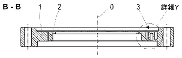
本発明に従うレンズマウントの全ての構成は、対称軸0を有する環状体によって形成されている。この環状体は、材料凹部を介して、外側マウントリング1、内側マウントリング2、及び、互いに120°だけずれるように配置された3つの接続構造3に分割されている。外側マウントリング1は少なくとも1つの端面を有し、該端面を介して内側マウントリングが他のレンズマウントにおけるちょうどこの種類の外側マウントリング1aに接続できる。レンズは内側マウントリング2内に取り付けられる。
All configurations of the lens mount according to the invention are formed by an annular body having an axis of
外側マウントリング1と内側マウントリング2を分割する材料凹部は、実施例の描写では環状カットとして示されている。しかしながら、内側マウントリング2を部分的に幅広くなるように構成するために、それら凹部は任意の有効な態様でカットされてもよい。
The material recess dividing the
内側マウントリング2はまた、レンズが受容されうる可撓性要素を用いた例により示されている。しかしながら、本発明に従うレンズマウントは特に、内側マウントリング2の構成とは完全に独立して接続構造3の構成に関する。
The
接続構造3は、互いに入り込んだ接続ウェブであって、対称軸0に対して半径方向及び軸方向に交互に配置された一連の少なくとも3つの接続ウェブである。内側マウントリング2に入り込んだ接続ウェブと外側マウントリング1に入り込んだ接続ウェブは望ましくは、環状体の対称軸0に対して半径方向に配置される。環状体の対称軸0はまた、内側マウントリング2の対称軸と外側マウントリング1の対称軸を示す。
The
新規ではないが、接続構造3が外側マウントリング1と内側マウントリング2の間の一体式接続であることが重要である。対応的に、レンズマウントが材料除去により作られるとき、接続ウェブは、材料切欠の間に残る材料ウェブであって、互いに接続するとともに撓み軸受によって外側マウントリング1及び内側マウントリング2にそれぞれ接続される材料ウェブである。場合によっては摩擦が克服されるまで接続ウェブを固く作動させ得る摩擦は、撓み軸受には無い。
Although not new, it is important that the
環状体のために選択された材料にかかわらず、引張剛性、曲げ剛性及び捩り剛性は、接続ウェブの量と寸法によって接続構造3のためになるべく低く調節され、それにより外側マウントリング1に発生する応力が内側マウントリング2に伝達することが防止される。言い換えれば、これは、接続構造3が伸長、屈曲及び捩れに関して必要なだけ柔らかくなる(弾性に富む)ように寸法決めされることを意味する。2つの隣接する撓み軸受の間の距離と等しい接続ウェブの長さl1,l2、半径方向及び軸方向の伸長に等しい接続ウェブの厚みd1,d2、及び対称軸0の周りの円に沿う伸長に等しい接続ウェブの幅bは、接続ウェブを寸法決めするために利用できる。
Regardless of the material selected for the annulus, the tensile stiffness, bending stiffness and torsional stiffness are adjusted as low as possible for the connecting
半径方向に延在する接続ウェブ−半径方向接続ウェブ3.1−は、軸方向に板バネのように作用し、軸方向に延在する接続ウェブ−軸方向接続ウェブ3.2−は、半径方向に板バネのように作用する。それらは好ましくは幅bにおいて同一であり、厚みd1,d2及び特にそれらの長さl1,l2に関して自由に寸法決めでき、それにより半径方向及び軸方向の曲げ剛性と捩り剛性が影響される。 Radially extending connection web-radial connection web 3.1- acts axially like a leaf spring, axially extending connection web-axial connection web 3.2- Acts like a leaf spring in the direction. They are preferably identical in width b and can be freely dimensioned with respect to thicknesses d 1 , d 2 and in particular their lengths l 1 , l 2 , thereby affecting the radial and axial bending and torsional stiffness Is done.
半径方向接続ウェブ3.1は最短の可能な長さl1と好ましくは比較的大きい厚みd1を有し、それにより接続構造3は軸方向に最大の可能な曲げ剛性を有する。半径方向の最低の可能な曲げ剛性のために、軸方向接続ウェブ3.2の長さl2はできるだけ長く、それらの厚みd2は好ましくは比較的小さい。
The radial connection web 3.1 has the shortest possible length l 1 and preferably a relatively large thickness d 1 , so that the
減少した幅bを有する接続構造3はますます低い捩り剛性を有する。
The
接続ウェブ3.1,3.2の互いへの移行部と、内側マウントリング2及び外側マウントリング1への接続構造3の移行部とにより形成された撓み軸受はそれぞれ、斜面4によって、関連する接続ウェブ3.1,3.2の厚みd1,d2に対して弱められてもよい(図3参照)。従って、斜面長さl4は、接続ウェブ3.1,3.2の長さl1,l2、厚みd1,d2及び幅bに加えて、曲げ剛性及び捩り剛性に影響を与える別のパラメータである。
The flexible bearings formed by the transitions of the connecting webs 3.1, 3.2 to each other and the transitions of the
軸方向接続ウェブ3.2が半径方向に弾性変形可能であり、すなわち半径方向に低い曲げ剛性を有し、それにより軸方向接続ウェブが撓み軸受の屈曲から生じる反力を吸収できることも重要である。半径方向及び軸方向接続ウェブ3.1,3.2が半径方向に固い場合、反力は内側マウントリング2に接続した撓み軸受に伝わり、そこで内側マウントリング2の変形をもたらす反力を生じさせてしまう。
It is also important that the axial connection web 3.2 is elastically deformable in the radial direction, i.e. has a low bending stiffness in the radial direction, so that the axial connection web can absorb the reaction forces resulting from the bending of the flexure bearing. . When the radial and axial connecting webs 3.1, 3.2 are rigid in the radial direction, the reaction force is transmitted to the flexural bearing connected to the
接続構造3の形状によってレンズマウントの半径方向寸法をなるべく小さく増大させる要件と相反するのは、半径方向接続ウェブ3.1の短い長さl1が高い軸方向の曲げ剛性をもたらし、軸方向接続ウェブ3.2の長い長さl2が低い半径方向の曲げ剛性をもたらすという事実である。接続構造3における軸方向の曲げ剛性に対する半径方向の曲げ剛性の比は長さ比(長さ係数)によって調節できる。
Contrary to the requirement to increase the radial dimension of the lens mount as small as possible by the shape of the
軸方向の曲げ剛性及び半径方向の曲げ剛性はまた、接続ウェブ3.1,3.2の厚みd1,d2によって決定される。ゆえに、選択される軸方向接続ウェブ3.2の厚みd2が半径方向接続ウェブ3.1の厚みd1より小さいと有利である。 The axial bending stiffness and the radial bending stiffness are also determined by the thicknesses d 1 , d 2 of the connecting webs 3.1, 3.2. It is therefore advantageous if the thickness d 2 of the selected axial connection web 3.2 is smaller than the thickness d 1 of the radial connection web 3.1.
図1a,1b,1cに示されるように、比較的なるべく小さい取り付けスペースを要求する3つの接続ウェブ3.1,3.2を備えた接続構造3のために、接続構造3が十分に半径方向に柔らかく、軸方向に固く、捩れに柔らかいように、接続ウェブ3.1,3.2の厚みd1,d2、幅b及び長さl1,l2が選択される。特に、図5,6,7に示されるように、環状体の厚み全体は軸方向接続ウェブ3.2の長さl2のために利用できる。さらに、図7は、接続構造3のための実施例を示しており、ここではこの接続構造3が軸方向接続ウェブ3.2を介して内側マウントリング2に移行する。同様にして、接続構造3の外側マウントリング1への移行部が軸方向接続ウェブ3.2によって形成されてもよいが、これは有利ではない。
As shown in FIGS. 1 a, 1 b, 1 c, the
設計及び安定性により書き取られた(指示された)接続ウェブ3.1,3.2の厚みd1,d2、幅b及び長さl1,l2のための最小寸法が可能でない場合、接続構造3は、図2a,2b,2cに示されるように5つの接続ウェブ3.1,3.2により形成され、又は例えば図6に示されるように大きめの奇数の接続ウェブ3.1,3.2により形成される。
If the minimum dimensions for the thicknesses d 1 , d 2 , width b and lengths l 1 , l 2 of the connecting webs 3.1, 3.2 written (designated) by design and stability are not possible The
外側マウントリング1に導入される力及びモーメントが主に、外側マウントリング1に接続した撓み軸受の屈曲及び回転を生じさせ、隣接する半径方向接続ウェブ3.1において反力及び反作用モーメントを生じさせる。反力及び反作用モーメントは、曲げ剛性及び捩り剛性に依存して、軸方向接続ウェブ3.2の変形により多かれ少なかれ一部吸収され、次の撓み軸受に一部伝達され、そこから再び一部吸収され、一部伝達される。接続ウェブ3.1,3.2は最小の曲げ剛性と最小の捩り剛性を常に有するので、反力は1つの接続ウェブ3.1,3.2単体によって完全には吸収できないが、一連の接続ウェブ3.1,3.2によってだんだん吸収される。
The forces and moments introduced into the
好ましくは、外側マウントリング1への接続構造3の移行部は外側マウントリング1の基準線の高さに位置する。引張応力も圧縮応力もこの基準線に沿って生じないように、外側マウントリング1の長さは屈曲の間変わらない。
Preferably, the transition portion of the
従って、有利な態様では、外側マウントリング1の端面に隣接する移行部の配置に比べて、基準線の周りの比較的小さい屈曲だけが接続構造3に導入される。
Thus, in an advantageous manner, only a relatively small bend around the reference line is introduced into the
技術的な理由のために、内側マウントリング2への接続構造3の移行部は好ましくは、外側マウントリング1の基準線により画定される平面内に配置される。
For technical reasons, the transition of the
しかしながら、それら移行部は他のいずれかの高さに、理想的には応力に関する技術的理由のために、内側マウントリング2の基準線の高さに配置されてもよい。
However, the transitions may be arranged at any other height, ideally at the height of the reference line of the
図3は、接続ウェブ3.1,3.2間の移行部の斜面4によって第1実施例の接続構造とは異なる接続構造3の構成を示す。ゆえに、撓み軸受として機能する移行部はより柔らかい。斜面4は斜面長さl4を有し、移行部の曲げ剛性はこれら斜面4の寸法により影響される。図4に示されるように、移行部が溝(ノッチ)により弱められると遜色のない効果が実現される。
FIG. 3 shows a configuration of the
接続構造3の構成にかかわらず、外側マウントリング1及び内側マウントリング2は従来技術のような多様な方法で構成されてもよい。外側マウントリング1の構成は、特に光学系にレンズマウントを取り付ける際に生じる様々な制約の結果、異なってもよい。内側マウントリング2の構成は、搭載レンズに対する半径方向又は軸方向接続、接着結合又は確動係合接続の結果、異なってもよい。内側マウントリング2は、応力に関して内側マウントリング2の周面からレンズと内側マウントリング2の接触領域を分離する構造的特徴、例えば上述した特許文献1から公知の可撓性セグメントを有してもよい。
Regardless of the configuration of the
0 対称軸
1 外側マウントリング
2 内側マウントリング
3 接続構造
3.1 半径方向接続ウェブ
3.2 軸方向接続ウェブ
4 斜面
b (接続ウェブ3.1,3.2の)幅
d1 (半径方向接続ウェブ3.1の)厚み
d2 (軸方向接続ウェブ3.2の)厚み
l1 (半径方向接続ウェブ3.1の)長さ
l2 (軸方向接続ウェブ3.2の)長さ
l4 斜面長さ
0 Axis of
Claims (8)
前記接続構造がそれぞれの場合に、移行部により接続された接続ウェブであって、半径方向接続ウェブと軸方向接続ウェブとして交互に構成された一連の少なくとも3つの接続ウェブにより形成され、前記半径方向接続ウェブが半径方向に或る長さを有し、前記軸方向接続ウェブが軸方向に或る長さを有し、前記軸方向接続ウェブの長さが前記半径方向接続ウェブの長さより大きく、
前記半径方向接続ウェブは前記軸方向に或る厚みを有し、前記軸方向接続ウェブは前記半径方向に或る厚みを有し、前記軸方向接続ウェブの厚みは前記半径方向接続ウェブの厚みより小さい、一体式レンズマウント。 Through the material recess, outer mount-ring, inner mount-ring, and, a three connecting structures which are arranged to be shifted by 120 ° from each other, connecting said outer mounting-ring and the inner mounting-ring is divided into connected structures are merely an body type lens mount having an annular body having an axis of symmetry,
Forming said if the connection structure is respectively a connected connecting web by transition, the radial connecting web parts and axially connected web blanking and to a series composed alternately at least three connecting webs is, the radial connecting web blanking has a certain length in the radial direction, it has a certain length the axial connecting web blanking is axially long saga the radius of the axial connecting web Bed direction connecting web Bed length Saya Ri large,
Said radial connecting web blanking has a certain Thickness in the axial direction, the axial connection web blanking has a certain Thickness in the radial direction, the thickness Hiroyoshi the radius of the axial connecting web Bed small Ri us thickness direction connecting web blanking one body type lens mount.
Wherein the connection structure is connected to the inner mount the height of the-ring reference line inner mount-ring, integral lens mount according to 請 Motomeko 7.
Applications Claiming Priority (2)
| Application Number | Priority Date | Filing Date | Title |
|---|---|---|---|
| DE102015115929.5A DE102015115929B3 (en) | 2015-09-21 | 2015-09-21 | Monolithic lens frame |
| DE102015115929.5 | 2015-09-21 |
Publications (3)
| Publication Number | Publication Date |
|---|---|
| JP2017072825A JP2017072825A (en) | 2017-04-13 |
| JP2017072825A5 JP2017072825A5 (en) | 2019-08-15 |
| JP6609536B2 true JP6609536B2 (en) | 2019-11-20 |
Family
ID=56937190
Family Applications (1)
| Application Number | Title | Priority Date | Filing Date |
|---|---|---|---|
| JP2016183765A Active JP6609536B2 (en) | 2015-09-21 | 2016-09-21 | Integrated lens mount |
Country Status (4)
| Country | Link |
|---|---|
| US (1) | US10036869B2 (en) |
| JP (1) | JP6609536B2 (en) |
| DE (1) | DE102015115929B3 (en) |
| IL (1) | IL247896B (en) |
Families Citing this family (16)
| Publication number | Priority date | Publication date | Assignee | Title |
|---|---|---|---|---|
| US10113837B2 (en) | 2015-11-03 | 2018-10-30 | N2 Imaging Systems, LLC | Non-contact optical connections for firearm accessories |
| US11304796B2 (en) * | 2017-09-25 | 2022-04-19 | Verily Life Sciences Llc | Reinforcement ring for intraocular lens |
| DE102018103053B3 (en) | 2018-02-12 | 2018-10-11 | Jenoptik Optical Systems Gmbh | Space-optimized lens frame with elastic connection structures |
| DE102018106010B3 (en) | 2018-03-15 | 2018-09-20 | Jenoptik Optical Systems Gmbh | Low tension lens mount with connecting bolt |
| US10753709B2 (en) | 2018-05-17 | 2020-08-25 | Sensors Unlimited, Inc. | Tactical rails, tactical rail systems, and firearm assemblies having tactical rails |
| US10645348B2 (en) | 2018-07-07 | 2020-05-05 | Sensors Unlimited, Inc. | Data communication between image sensors and image displays |
| US11079202B2 (en) | 2018-07-07 | 2021-08-03 | Sensors Unlimited, Inc. | Boresighting peripherals to digital weapon sights |
| CN110824656B (en) * | 2018-08-07 | 2022-05-27 | 宁波舜宇车载光学技术有限公司 | Optical lens and buffer lens and manufacturing method thereof |
| US10742913B2 (en) | 2018-08-08 | 2020-08-11 | N2 Imaging Systems, LLC | Shutterless calibration |
| US10921578B2 (en) | 2018-09-07 | 2021-02-16 | Sensors Unlimited, Inc. | Eyecups for optics |
| US11122698B2 (en) | 2018-11-06 | 2021-09-14 | N2 Imaging Systems, LLC | Low stress electronic board retainers and assemblies |
| US10801813B2 (en) | 2018-11-07 | 2020-10-13 | N2 Imaging Systems, LLC | Adjustable-power data rail on a digital weapon sight |
| US10796860B2 (en) | 2018-12-12 | 2020-10-06 | N2 Imaging Systems, LLC | Hermetically sealed over-molded button assembly |
| US11143838B2 (en) | 2019-01-08 | 2021-10-12 | N2 Imaging Systems, LLC | Optical element retainers |
| CN113805299A (en) * | 2020-06-11 | 2021-12-17 | 玉晶光电(厦门)有限公司 | Gasket ring |
| DE102022124609A1 (en) | 2022-09-26 | 2024-03-28 | Jenoptik Optical Systems Gmbh | Lens mount, laser device, method for making a monolithic lens mount, method for making a lens mount |
Family Cites Families (14)
| Publication number | Priority date | Publication date | Assignee | Title |
|---|---|---|---|---|
| US4733945A (en) * | 1986-01-15 | 1988-03-29 | The Perkin-Elmer Corporation | Precision lens mounting |
| US5428482A (en) * | 1991-11-04 | 1995-06-27 | General Signal Corporation | Decoupled mount for optical element and stacked annuli assembly |
| US5353166A (en) * | 1991-11-04 | 1994-10-04 | General Signal Corporation | Mounting system for optical annulus in lens assembly |
| US7274430B2 (en) | 1998-02-20 | 2007-09-25 | Carl Zeiss Smt Ag | Optical arrangement and projection exposure system for microlithography with passive thermal compensation |
| DE19807094A1 (en) * | 1998-02-20 | 1999-08-26 | Zeiss Carl Fa | Optical arrangement and projection exposure system of microlithography with passive thermal compensation |
| DE19825716A1 (en) * | 1998-06-09 | 1999-12-16 | Zeiss Carl Fa | Optical element and socket assembly |
| DE19908554A1 (en) * | 1999-02-27 | 2000-08-31 | Zeiss Carl Fa | Adjustable assembly |
| EP1094348B1 (en) * | 1999-10-06 | 2005-04-20 | JENOPTIK Aktiengesellschaft | Elastic lens mount |
| DE10030005A1 (en) | 2000-06-17 | 2001-12-20 | Zeiss Carl | Objective, in particular a projection objective in semiconductor lithography |
| EP1310829B1 (en) * | 2001-11-07 | 2007-05-02 | ASML Netherlands B.V. | Lithographic apparatus and device manufacturing method |
| TWI244119B (en) | 2001-11-07 | 2005-11-21 | Asml Netherlands Bv | Lithographic apparatus and device manufacturing method |
| DE102004025832A1 (en) * | 2004-05-24 | 2005-12-22 | Carl Zeiss Smt Ag | Optics module for a lens |
| JP2011090250A (en) * | 2009-10-26 | 2011-05-06 | Canon Inc | Optical device, exposure apparatus using same, and device manufacturing method |
| US8711495B2 (en) * | 2012-10-01 | 2014-04-29 | Apple Inc. | MEMS autofocus actuator |
-
2015
- 2015-09-21 DE DE102015115929.5A patent/DE102015115929B3/en active Active
-
2016
- 2016-09-19 IL IL247896A patent/IL247896B/en active IP Right Grant
- 2016-09-21 JP JP2016183765A patent/JP6609536B2/en active Active
- 2016-09-21 US US15/271,716 patent/US10036869B2/en active Active
Also Published As
| Publication number | Publication date |
|---|---|
| JP2017072825A (en) | 2017-04-13 |
| IL247896A0 (en) | 2017-01-31 |
| IL247896B (en) | 2021-04-29 |
| US20170082826A1 (en) | 2017-03-23 |
| DE102015115929B3 (en) | 2016-10-06 |
| US10036869B2 (en) | 2018-07-31 |
Similar Documents
| Publication | Publication Date | Title |
|---|---|---|
| JP6609536B2 (en) | Integrated lens mount | |
| JP5728457B2 (en) | Flexible shaft coupling and manufacturing method thereof | |
| JP6193547B2 (en) | Flexible diaphragm coupling assembly for rotary axial axis | |
| EP0918950B1 (en) | Flexible coupling having re-entrant curved columns for maintaining high torsional rigidity despite misalignment | |
| JP5535396B2 (en) | Linear actuator | |
| JP2017521719A (en) | Precision optical mount for optical devices | |
| US20150377312A1 (en) | Partitioned elastomeric journal bearing assemblies, systems and methods | |
| JP4315453B2 (en) | Elastic body thickness setting method for flexible shaft joint | |
| US10216094B2 (en) | Support device and method for supporting lens and support component for supporting functional element | |
| JP6637862B2 (en) | Enhanced lens mount | |
| WO2014004687A1 (en) | Flexible coupling | |
| JP2005291238A (en) | Flexible shaft joint | |
| JP2020041669A (en) | Supporting device | |
| US20170219796A1 (en) | Deformable mirror | |
| WO2016147507A1 (en) | Capacitive actuator motor, capacitive actuator, and capacitive actuator unit | |
| JP4905316B2 (en) | Gear and image forming apparatus using the gear | |
| US20180210191A1 (en) | Suspension system of optical actuator | |
| JP2006184485A (en) | Optical device having frame fixation structure | |
| JP2021528607A (en) | Configurations for transmitting torsional torque to achieve high usage of certain materials, especially in the form of torsion springs or drive shafts made of composite fiber materials. | |
| US20100247234A1 (en) | System for Precisely Adjusting the Space Between Two Elements | |
| JP7113588B1 (en) | connecting member | |
| JP2002372068A (en) | Flexible coupling | |
| JPWO2020129816A1 (en) | Displacement expansion mechanism and actuator | |
| JP2006275079A (en) | Flexible shaft joint | |
| JP6786236B2 (en) | Shock absorber |
Legal Events
| Date | Code | Title | Description |
|---|---|---|---|
| A521 | Request for written amendment filed |
Free format text: JAPANESE INTERMEDIATE CODE: A523 Effective date: 20190701 |
|
| A621 | Written request for application examination |
Free format text: JAPANESE INTERMEDIATE CODE: A621 Effective date: 20190701 |
|
| A871 | Explanation of circumstances concerning accelerated examination |
Free format text: JAPANESE INTERMEDIATE CODE: A871 Effective date: 20190701 |
|
| A975 | Report on accelerated examination |
Free format text: JAPANESE INTERMEDIATE CODE: A971005 Effective date: 20190927 |
|
| TRDD | Decision of grant or rejection written | ||
| A01 | Written decision to grant a patent or to grant a registration (utility model) |
Free format text: JAPANESE INTERMEDIATE CODE: A01 Effective date: 20191008 |
|
| A61 | First payment of annual fees (during grant procedure) |
Free format text: JAPANESE INTERMEDIATE CODE: A61 Effective date: 20191028 |
|
| R150 | Certificate of patent or registration of utility model |
Ref document number: 6609536 Country of ref document: JP Free format text: JAPANESE INTERMEDIATE CODE: R150 |
|
| R250 | Receipt of annual fees |
Free format text: JAPANESE INTERMEDIATE CODE: R250 |
|
| R250 | Receipt of annual fees |
Free format text: JAPANESE INTERMEDIATE CODE: R250 |