EP3615768B1 - Bohrlochenergieerzeugungssystem und optimiertes leistungsregelverfahren dafür - Google Patents
Bohrlochenergieerzeugungssystem und optimiertes leistungsregelverfahren dafür Download PDFInfo
- Publication number
- EP3615768B1 EP3615768B1 EP18790795.1A EP18790795A EP3615768B1 EP 3615768 B1 EP3615768 B1 EP 3615768B1 EP 18790795 A EP18790795 A EP 18790795A EP 3615768 B1 EP3615768 B1 EP 3615768B1
- Authority
- EP
- European Patent Office
- Prior art keywords
- generator
- voltage
- optimized
- turbine
- load
- Prior art date
- Legal status (The legal status is an assumption and is not a legal conclusion. Google has not performed a legal analysis and makes no representation as to the accuracy of the status listed.)
- Active
Links
Images






Classifications
-
- F—MECHANICAL ENGINEERING; LIGHTING; HEATING; WEAPONS; BLASTING
- F03—MACHINES OR ENGINES FOR LIQUIDS; WIND, SPRING, OR WEIGHT MOTORS; PRODUCING MECHANICAL POWER OR A REACTIVE PROPULSIVE THRUST, NOT OTHERWISE PROVIDED FOR
- F03B—MACHINES OR ENGINES FOR LIQUIDS
- F03B13/00—Adaptations of machines or engines for special use; Combinations of machines or engines with driving or driven apparatus; Power stations or aggregates
-
- E—FIXED CONSTRUCTIONS
- E21—EARTH OR ROCK DRILLING; MINING
- E21B—EARTH OR ROCK DRILLING; OBTAINING OIL, GAS, WATER, SOLUBLE OR MELTABLE MATERIALS OR A SLURRY OF MINERALS FROM WELLS
- E21B41/00—Equipment or details not covered by groups E21B15/00 - E21B40/00
- E21B41/0085—Adaptations of electric power generating means for use in boreholes
-
- F—MECHANICAL ENGINEERING; LIGHTING; HEATING; WEAPONS; BLASTING
- F03—MACHINES OR ENGINES FOR LIQUIDS; WIND, SPRING, OR WEIGHT MOTORS; PRODUCING MECHANICAL POWER OR A REACTIVE PROPULSIVE THRUST, NOT OTHERWISE PROVIDED FOR
- F03B—MACHINES OR ENGINES FOR LIQUIDS
- F03B13/00—Adaptations of machines or engines for special use; Combinations of machines or engines with driving or driven apparatus; Power stations or aggregates
- F03B13/02—Adaptations for drilling wells
-
- F—MECHANICAL ENGINEERING; LIGHTING; HEATING; WEAPONS; BLASTING
- F03—MACHINES OR ENGINES FOR LIQUIDS; WIND, SPRING, OR WEIGHT MOTORS; PRODUCING MECHANICAL POWER OR A REACTIVE PROPULSIVE THRUST, NOT OTHERWISE PROVIDED FOR
- F03B—MACHINES OR ENGINES FOR LIQUIDS
- F03B15/00—Controlling
-
- H—ELECTRICITY
- H02—GENERATION; CONVERSION OR DISTRIBUTION OF ELECTRIC POWER
- H02J—ELECTRIC POWER NETWORKS; CIRCUIT ARRANGEMENTS OR SYSTEMS FOR SUPPLYING OR DISTRIBUTING ELECTRIC POWER; SYSTEMS FOR STORING ELECTRIC ENERGY
- H02J1/00—Circuit arrangements for DC mains or DC distribution networks
- H02J1/10—Parallel operation of DC sources
- H02J1/102—Parallel operation of DC sources being switching converters
-
- H—ELECTRICITY
- H02—GENERATION; CONVERSION OR DISTRIBUTION OF ELECTRIC POWER
- H02P—CONTROL OR REGULATION OF ELECTRIC MOTORS, ELECTRIC GENERATORS OR DYNAMO-ELECTRIC CONVERTERS; CONTROLLING TRANSFORMERS, REACTORS OR CHOKE COILS
- H02P9/00—Arrangements for controlling electric generators for the purpose of obtaining a desired output
- H02P9/04—Control effected upon non-electric prime mover and dependent upon electric output value of the generator
-
- F—MECHANICAL ENGINEERING; LIGHTING; HEATING; WEAPONS; BLASTING
- F05—INDEXING SCHEMES RELATING TO ENGINES OR PUMPS IN VARIOUS SUBCLASSES OF CLASSES F01-F04
- F05B—INDEXING SCHEME RELATING TO WIND, SPRING, WEIGHT, INERTIA OR LIKE MOTORS, TO MACHINES OR ENGINES FOR LIQUIDS COVERED BY SUBCLASSES F03B, F03D AND F03G
- F05B2220/00—Application
- F05B2220/70—Application in combination with
- F05B2220/706—Application in combination with an electrical generator
- F05B2220/7062—Application in combination with an electrical generator of the direct current (D.C.) type
-
- F—MECHANICAL ENGINEERING; LIGHTING; HEATING; WEAPONS; BLASTING
- F05—INDEXING SCHEMES RELATING TO ENGINES OR PUMPS IN VARIOUS SUBCLASSES OF CLASSES F01-F04
- F05B—INDEXING SCHEME RELATING TO WIND, SPRING, WEIGHT, INERTIA OR LIKE MOTORS, TO MACHINES OR ENGINES FOR LIQUIDS COVERED BY SUBCLASSES F03B, F03D AND F03G
- F05B2270/00—Control
- F05B2270/10—Purpose of the control system
- F05B2270/20—Purpose of the control system to optimise the performance of a machine
-
- H—ELECTRICITY
- H02—GENERATION; CONVERSION OR DISTRIBUTION OF ELECTRIC POWER
- H02P—CONTROL OR REGULATION OF ELECTRIC MOTORS, ELECTRIC GENERATORS OR DYNAMO-ELECTRIC CONVERTERS; CONTROLLING TRANSFORMERS, REACTORS OR CHOKE COILS
- H02P2101/00—Special adaptation of control arrangements for generators
- H02P2101/10—Special adaptation of control arrangements for generators for water-driven turbines
Definitions
- This disclosure relates generally to power generation systems, and more particularly to a downhole power generation system and an optimized power control method for a downhole power generation system.
- Downhole drilling or sensing systems are used in oil and gas exploration and production wells. Some downhole sensors for fracturing monitoring and long-term production surveillance, downhole data communication module and other downhole loads are often applied to the downhole drilling or sensing systems for performing their respective functions. These downhole loads require power to operate. It is well known in the art to use a turbine generator system. Flow of a downhole fluid, for example production fluid drives a turbine of the turbine generator system to rotate and generate rotational energy. The turbine generator system uses an electrical generator to convert the rotational energy from the turbine to electrical energy, and power can be thus provided to these downhole loads.
- US 2016/0348478 discloses a system and method for supplying downhole power using a high-impedance alternator.
- a downhole power generation system is provided as claimed in claim 1.
- an optimized power control method for a downhole power generation system is provided as claimed in claim 9.
- connection and “coupled” are not restricted to physical or mechanical connections or couplings, and can include electrical connections or couplings, whether direct or indirect.
- Terms indicating specific locations such as “top”, “bottom”, “left”, and “right”, are descriptions with reference to specific accompanying drawings. Embodiments disclosed in the present disclosure may be placed in a manner different from that shown in the figures. Therefore, the location terms used herein should not be limited to locations described in specific embodiments.
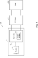
- FIG. 1 illustrates a schematic diagram of a downhole power generation system.
- the downhole power generation system uses a turbine generator system 1 to provide an output power P load for a load 300.
- the turbine generator system 1 can be driven by flow of a downhole fluid to rotate and output a direct current (DC) voltage V load to the load 300.
- DC direct current
- the turbine generator system 1 may be driven to rotate by the downhole fluid having different flow rate F and may have different rotational speed N.
- FIG. 2 illustrates characteristics curves of the output power P load in relation to the rotational speed N of the turbine generator system 1 at different flow rates F of the downhole fluid.
- the turbine generator system 1 has different output power-rotational speed (P load -N) curves respectively.
- the maximum power output points of the turbine generator system 1 at different flow rates F are different.
- FIG. 3 illustrates characteristics curves of the output voltage V load in relation to the rotational speed N of the turbine generator system 1 at different flow rates F of the downhole fluid.
- the turbine generator system 1 has different output voltage-rotational speed (V load -N) curves respectively.
- V 0 represents an open circuit voltage of the turbine generator system 1 when the turbine generator system 1 is disconnected from the load 300.
- the open circuit voltage V 0 of the turbine generator system 1 is defined as a constant no load voltage of the turbine generator system 1 after disconnection from the load 300.
- characteristics curves of the output power P load in relation to the output voltage V load of the turbine generator system 1 at the flow rates of 500GPM and 700GPM can be plotted, as shown in FIG. 4 .
- the turbine generator system 1 has different output power-output voltage (P load -V load ) curves respectively.
- the output power P load of the turbine generator system 1 can be changed by adjusting the output voltage V load of the turbine generator system 1.
- characteristics curves of the output power P load in relation to the voltage ratio R of the turbine generator system 1 at the flow rates of 500GPM and 700GPM can be plotted, as shown in FIG. 5 .
- the output power P load of the turbine generator system 1 can be controlled with the voltage ratio R.
- the maximum output power points of the turbine generator system 1 at the flow rates of 500GPM and 700GPM correspond to the same voltage ratio R opc which is for example about 0.58 in this case.
- FIG. 5 is shown only using the two flow rates of 500GPM and 700GPM, this voltage ratio R opc corresponding to the maximum output power point of the turbine generator system 1 is constant for any flow rate F of the downhole fluid.
- E represents the system efficiency of the turbine generator system 1
- P in represents an input power of the turbine generator system 1.
- R the system efficiency E of the turbine generator system 1
- the maximum system efficiency points of the turbine generator system 1 at the flow rates of 500GPM and 700GPM correspond to the same voltage ratio R opc which is for example about 0.75 in this case.
- R opc this voltage ratio opc corresponding to the maximum system efficiency point of the turbine generator system 1 is constant for any flow rate F of the downhole fluid.
- FIGS. 2-6 are demonstrated only using two flow rates of the downhole fluid, the above conclusion can be valid for different operation conditions of the turbine generator system 1, i.e. any flow rate F of the downhole fluid.
- the voltage ratio corresponding to the maximum output power point of the turbine generator system 1 in FIG. 5 or the voltage ratio corresponding to the maximum system efficiency point of the turbine generator system 1 in FIG. 6 may be defined as a voltage ratio for optimized power control of the turbine generator system 1 (also called as an optimized voltage ratio), R opc .
- FIG. 7 illustrates a schematic diagram of a downhole power generation system 100 in accordance with an embodiment of the present disclosure.
- the downhole power generation system 100 includes a turbine generator system 1 and the turbine generation system 1 can provide power to a load 300.
- the load 300 may for example include sensors such as temperature and pressure sensor, and flow rate sensor, or a data communication module.
- the turbine generator system 1 includes a turbine 11, and a generator 12 coupled with the turbine 11 and having an AC-DC (Alternating Current-Direct Current) rectifier 13.
- the turbine 11 can be driven by flow of a downhole fluid to rotate.
- the generator 12 can convert rotational energy from the turbine 11 to electrical energy and outputting a direct current (DC) voltage.
- DC direct current
- the downhole power generation system 100 of the present disclosure further includes an optimized power control (OPC) unit 2.
- the turbine generator system 1 is coupled to the load 300 via the OPC unit 2.
- the OPC unit 2 can control to regulate an output voltage of the generator 12 and provide a regulated output voltage V r to the load 300 so that the turbine generator system 1 has an optimized power output.
- the OPC unit 2 may be implemented by hardware, software, or a combination thereof.
- the optimized power output targets on a maximum power output of the turbine generator system 1 or a maximum system efficiency of the turbine generator system 1.
- the OPC unit 2 may include a switch 21, a voltage measuring device 22 and a DC-DC voltage regulator 23.
- the OPC unit 2 can regularly disconnects the generator 12 from the load 300.
- the switch 21 is turned off and then, the voltage measuring device 22 of the OPC unit 2 measures an output voltage of the generator 12 after disconnection.
- the OPC unit 2 reconnects the generator 12 with the load 300.
- the switch 21 is turned on and then, the DC-DC voltage regulator 23 of the OPC unit 2 regulates the output voltage of the generator 12 equal to the measured output voltage of the generator 12 multiplied by a voltage ratio predefined for optimized power control of the turbine generator system 1 (i.e. optimized voltage ratio), R opc .
- V r V m ⁇ R opc
- V m represent a measured output voltage of the generator 12
- V r represents a regulated voltage of the generator 12.
- the optimized voltage ratio R opc is equal to a ratio of an optimized power control (OPC) voltage of the generator 12 to an open circuit voltage of the generator 12 at any one flow rate of the downhole fluid.
- OPC optimized power control
- the OPC voltage of the generator 12 is defined as a voltage in which the turbine generator system 1 has the optimized power output at the any one flow rate of the downhole fluid.
- R opc V opc V 0
- V opc represents the OPC voltage of the generator 12.
- V opc may represent a voltage of the generator 12 corresponding to the maximum power output at the any one flow rate of the downhole fluid, or V opc may represent a voltage of the generator 12 corresponding to the maximum system efficiency at the any one flow rate of the downhole fluid.
- the voltage ratio for optimized power control of the turbine generator system i.e. the optimized voltage ratio R opc is constant for different flow rates of the downhole fluid.
- the maximum power output of the turbine generator system 1 will be taken as an illustrative example of the optimized power output of the turbine generator system 1 to describe.
- measuring the output voltage of the generator 12 after disconnection may include two cases as follows.
- the voltage measuring device 22 of the OPC unit 2 can measure an open circuit voltage V 0 of the generator 12.
- the open circuit voltage V 0 of the generator 12 is defined as the constant no load voltage of generator 12 after disconnection.
- the DC-DC voltage regulator 23 of the OPC unit 2 can regulate the output voltage of the generator 12 equal to the measured open circuit voltage of the generator multiplied by the optimized voltage ratio R opc .
- V r V 0 ⁇ R opc
- the regulated voltage V r of the generator 12 can be easily calculated according to equation (5).
- the voltage measuring device 22 of the OPC unit 2 can measure a cutoff voltage V cutoff of the generator 12 after the predetermined cutoff time T cutoff .
- the predetermined cutoff time T cutoff may depend on the characteristics of the turbine generator system 1 and may be given in advance in the OPC unit 2.
- the OPC unit 2 reconnects the generator 12 with the load 300, and then, the DC-DC voltage regulator 23 of the OPC unit 2 can regulate the output voltage of the generator 12 equal to the measured cut-off voltage V cutoff of the generator 12 multiplied by the optimized voltage ratio R opc .
- V r V cutoff ⁇ R opc
- the regulated voltage V r of the generator 12 can be easily calculated according to equation (6).
- the OPC unit 2 can repeat the steps of disconnecting, measuring, reconnecting and regulating above till the measured cutoff voltage V cutoff of the generator 12 approaches constant.
- the turbine generator system 1 will finally achive the maximum power output.
- FIG. 10 illustrates a schematic diagram for explaining the optimized power control process above.
- line 1 represents a torque-rotational speed (T-N) curve of the generator 12 and curve 2 represents an output power-rotational speed (P load -N) curve of the generator 12.
- the turbine generator system 1 is driven by the downhole fluid having a certain flow rate to operate.
- the generator 12 works at a stable working point, for example point A.
- the switch 21 is turned off, the OPC unit 2 disconnects the generator 12 from the load 300, at this time, the rotational speed N of the generator 12 increases.
- T cutoff the generator 12 operates at for example point A' and a cutoff voltage V cutoff of the generator 12 at point A' is measured.
- the switch 21 is turned on.
- the OPC unit 2 reconnects the generator 12 with the load 300, and regulates the output voltage of the generator 12 equal to the measured cut-off voltage V cutoff of the generator 12 multiplied by the optimized voltage ratio R opc .
- the generator 12 will work at the next stable working point, for example point C'. After one round above, the generator's working point changes from point A to point C'.
- the generator 12 will repeat a pattern like A->A'->C' above and change from the stable working point C' to another stable working point (not labeled). After several rounds of repeating, the generator 12 will finally work towards the maximum power output point C.
- the turbine generator system 1 will achive the maximum power output.
- the OPC function of the OPC unit 2 is explained by taking the maximum power output as an example of the optimized power output, the OPC function of the OPC unit 2 can be similarly applied to the maximum system efficiency of the turbine generator system 1 without departing the substance of the present disclosure.
- the downhole power generation system 100 of the first embodiment can achive the maximum power output or the maximum system efficiency by the optimized power controlling of the OPC unit 2.
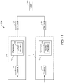
- FIG. 11 illustrates a schematic diagram of a downhole power generation system 200 in accordance with another embodiment of the present disclosure.
- the downhole power generation system 200 of the second embodiment may include a plurality of turbine generator systems 1.
- the plurality of turbines 11 in the plurality of turbine generator systems 1 are so positioned physically that one or more turbines 11 is exposed to the downhole fluid.
- the flow of the downhole fluid may drive the one or more turbines 11 to rotate.
- the plurality of turbine generator systems 1 can provide one or more powers to the load 300.
- a multiplicity of turbines 11 can ensure that one or more of the plurality of turbines 11 is exposed to the flow of the downhole fluid in a multiphase environment, such the multi-turbine power generation configuration can achieve a reliable and redundant power supply for the load 300.
- the plurality of turbines 11 may be driven by the downhole fluid having different flow rates due to respective different physical positions and may thus have different rotational speeds. Due to different physical positions of respective turbines 11 of the plurality of turbine generator systems 1, the plurality of turbine generator systems 1 may generate different amounts of power. All the different amounts of power can be provided to the load 300. The amounts of power generated from the plurality of turbine generator systems 1 depend on physical positions of respective turbines 11.
- the downhole power generation system 200 of the second embodiment allows each of the plurality of turbines 11 to rotate at the different rotational speed and maximize the power generated from each of the plurality of turbines 11.
- the plurality of turbines 11 in the plurality of turbine generator systems 1 may be distributed around a flow path of the downhole fluid.
- the downhole fluid flows within a casing, and the plurality of turbines 11 may be spacedly arranged at an inner circumferential wall of the casing or deployed closer to the center of the casing.
- the plurality of turbines 11 distributed in the multiphase environment can ensure that the flow of the downhole fluid can drive at least one turbine 11 to operate and it thus provide a redundant and more reliable power supply to the load 300.
- the downhole fluid When the flow rate of the downhole fluid is sufficient, the downhole fluid may be full of the whole casing, in this circumstance, all the turbines 11 may operate, but the plurality of turbines 11 may be driven by the downhole fluid having different flow rates.
- the downhole fluid may include many impurities, the flow of the downhole fluid at a top inner wall of the casing may be dominated by gas and the flow of the downhole fluid at a bottom inner wall of the casing may be blocked by sedimentation.
- the flow of the downhole fluid in the multiphase environment may be different.
- the downhole fluid When the flow rate of the downhole fluid is less, the downhole fluid may not fill the whole casing, in this circumstance, only a portion of the plurality of turbines 11 may operate and may be also driven by the downhole fluid having different flow rates.
- the number and the distribution of turbines 11 of the present disclosure can be suitably selected based on the downhole fluid and its flow condition and in combination of product costs.
- the downhole power generation system 200 of the second embodiment can not only allow each of the plurality of turbines to operate at different rotational speed and maximize the output power generated from each of the plurality of turbine generator systems 1 or system efficiency, but also achieve a reliable and redundant power supply for the load 300.
- FIG. 12 illustrates a flow chart of an optimized power control method for a downhole power generation system in accordance with an embodiment of the present disclosure.
- the optimized power control method may be applied to the downhole power generation system 100 of the first embodiment and the downhole power generation system 200 of the second embodiment.
- the optimized power control method may include the steps as follows.
- hydro energy from flow of a downhole fluid may be harvested via one or more turbines 11 in one or more turbine generator systems 1, and one or more rotational energies may be thus generated.
- the multiple turbines 11 may be so positioned physically that one or more turbines is exposed to the downhole fluid. Due to different physical positions of the plurality of turbines 11, the one or more turbines 11 may be driven by the downhole fluid having different flow rates, and thus the one or more rotational energies generated may be different.
- the one or more rotational energies from the one or more turbines 11 may be converted to one or more electrical energies and outputting one or more DC voltages by one or more generators 12 with the AC-DC rectifier 13 in one or more turbine generator systems 1. Because the one or more rotational energies generated may be different, the one or more DC voltages output may have different voltage values.
- an output voltage of each of the one or more generators 12 may be controlled to regulate.
- a regulated output voltage of each generator 12 may be provided to a load 300 so that each of the one more turbine generator systems 1 has an optimized power output.
- the optimized power output targets on a maximum power output or a maximum system efficiency of each turbine generator system 1.
- FIG. 13 illustrates steps how to control to regulate the output voltage of each generator 12 in one case. As shown in FIG. 13 , in block B311, each generator 12 is disconnected from the load 300, and then the process goes to block B312.
- an output voltage of each generator 12 is measured after disconnection of each generator 12 from the load 300 for an enough long time.
- the measured output voltage of each generator 12 is an open circuit voltage V 0 of each generator 12.
- the open circuit voltage V 0 of each generator 12 is defined as a constant no load voltage of each generator 12 after disconnection.
- each generator 12 is reconnected with the load 300, and then the process goes to block B314.
- each generator 12 is regulated equal to the measured open circuit voltage V 0 of each generator 12 in block B312 multiplied by an optimized voltage ratio R opc predefined for optimized power control of each turbine generator system 1, as shown in equation (5) above.
- the optimized voltage ratio R opc of each turbine generator system 1 is equal to a ratio of an optimized power control voltage V opc to an open circuit voltage V 0 of each generator 12 at any one rotational speed of each generator 12.
- the optimized power control voltage V opc of each generator 12 is defined as a voltage in which each turbine generator system 1 has the optimized power output, and the open circuit voltage V 0 of each generator 12 is defined as a constant no load voltage of each generator 12.
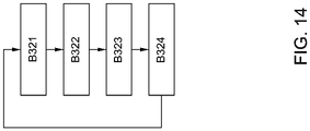
- FIG. 14 illustrates steps how to control to regulate the output voltage of each generator 12 in another case. As shown in FIG. 14 , in block B321, each generator 12 is disconnected from the load 300, and then the process goes to block B322.
- a cutoff voltage V cutoff of each generator 12 is measured after a predetermined cutoff time T cutoff .
- the predetermined cutoff time T cutoff may depend on the characteristics of each turbine generator system 1.
- each generator 12 is reconnected with the load 300, and then the process goes to block B324.
- each generator 12 is regulated equal to the measured cutoff voltage V cutoff of each generator 12 in block B322 multiplied by the optimized voltage ratio R opc of each turbine generator system 1, as shown in equation (6) above.
- the optimized power control method of the present disclosure can not only allow each of the plurality of turbines 11 to operate at different rotational speed and maximize the output power generated from each of the plurality of turbine generator systems 1 or system efficiency, but also achieve a reliable and redundant power supply for the load 300.
- steps of the optimized power control method for the downhole power generation system in accordance with embodiments of the present disclosure are illustrated as functional blocks, the order of the blocks and the separation of the steps among the various blocks shown in FIGS. 12-14 are not intended to be limiting.
- the blocks may be performed in a different order and a step associated with one block may be combined with one or more other blocks or may be sub-divided into a number of blocks.
Landscapes
- Engineering & Computer Science (AREA)
- Chemical & Material Sciences (AREA)
- Combustion & Propulsion (AREA)
- Mechanical Engineering (AREA)
- General Engineering & Computer Science (AREA)
- Life Sciences & Earth Sciences (AREA)
- Geology (AREA)
- Mining & Mineral Resources (AREA)
- Physics & Mathematics (AREA)
- Environmental & Geological Engineering (AREA)
- Fluid Mechanics (AREA)
- General Life Sciences & Earth Sciences (AREA)
- Geochemistry & Mineralogy (AREA)
- Power Engineering (AREA)
- Control Of Eletrric Generators (AREA)
Claims (12)
- Bohrlochenergieerzeugungssystem, umfassend:
ein Turbinengeneratorsystem (1), umfassend:eine Turbine (11), die durch den Durchfluss eines Bohrlochfluids zum Drehen angetrieben wird; undeinen Generator (12), der mit der Turbine gekoppelt ist und einen AC-DC-Gleichrichter (13) aufweist, wobei der Generator zum Umwandeln von Rotationsenergie von der Turbine in elektrische Energie und Ausgeben einer Gleichspannung konfiguriert ist; undeine optimierte Leistungsregeleinheit (2), über die das Turbinengeneratorsystem mit einem Verbraucher (300) gekoppelt ist, wobei die optimierte Leistungsregeleinheit zum Steuern konfiguriert ist, um eine Ausgangsspannung des Generators zu regeln und eine geregelte Ausgangsspannung für den Verbraucher bereitzustellen, sodass das Turbinengeneratorsystem eine optimierte Leistungsabgabe aufweist,dadurch gekennzeichnet, dass die optimierte Leistungsregeleinheit konfiguriert ist, um den Generator regelmäßig von dem Verbraucher zu trennen und eine Ausgangsspannung des Generators nach dem Trennen zu messen und den Generator erneut mit dem Verbraucher zu verbinden und die Ausgangsspannung des Generators gleich der gemessenen Ausgangsspannung des Generators, multipliziert mit einem optimierten Spannungsverhältnis, das für optimierte Leistungsregelung vordefiniert ist, zu regeln,wobei das optimierte Spannungsverhältnis gleich einem Verhältnis einer optimierten Leistungsregelspannung des Generators zu einer Leerlaufspannung des Generators in einer beliebigen Durchflussrate des Bohrlochfluids ist, wobei die optimierte Leistungsregelspannung des Generators als Spannung definiert ist, bei der das Turbinengeneratorsystem die optimierte Leistungsabgabe aufweist, und die Leerlaufspannung des Generators als konstante Leerlaufspannung des Generators ohne Verbraucher definiert ist. - Bohrlochenergieerzeugungssystem nach Anspruch 1, wobei die optimierte Leistungsregeleinheit zum Trennen des Generators von dem Verbraucher und Messen einer Leerlaufspannung des Generators und zum erneuten Verbinden des Generators mit dem Verbraucher und Regeln der Ausgangsspannung des Generators gleich der gemessenen Leerlaufspannung des Generators, multipliziert mit dem optimierten Spannungsverhältnis, konfiguriert ist, wobei die Leerlaufspannung des Generators nach dem Trennen als konstante Leerlaufspannung des Generators ohne Verbraucher definiert ist.
- Bohrlochenergieerzeugungssystem nach Anspruch 1, wobei die optimierte Leistungsregeleinheit konfiguriert ist, um den Generator von dem Verbraucher zu trennen und eine Abschaltspannung des Generators nach einer vorbestimmten Trennzeit zu messen und den Generator mit dem Verbraucher neu zu verbinden und die Ausgangsspannung des Generators gleich der gemessenen Abschaltspannung des Generators, multipliziert mit dem optimierten Spannungsverhältnis, zu regeln.
- Bohrlochenergieerzeugungssystem nach Anspruch 3, wobei die optimierte Leistungsregeleinheit zum Wiederholen der Schritte des Trennens, Messens, Wiederverbindens und Regelns konfiguriert ist, bis sich die gemessene Abschaltspannung des Generators einer konstanten nähert.
- Bohrlochenergieerzeugungssystem nach Anspruch 1, wobei das optimierte Spannungsverhältnis für unterschiedliche Durchflussraten des Bohrlochfluids konstant ist.
- Bohrlochenergieerzeugungssystem nach Anspruch 1, wobei die optimierte Leistungsabgabe auf eine maximale Leistungsabgabe oder eine maximale Systemeffizienz des Turbinengeneratorsystems abzielt.
- Bohrlochenergieerzeugungssystem nach einem der Ansprüche 1 bis 6, wobei das Bohrlochenergieerzeugungssystem eine Vielzahl von Turbinengeneratorsystemen umfasst, die jeweils die Turbine, den Generator und die optimierte Leistungsregeleinheit umfassen, und die Vielzahl von Turbinen in der Vielzahl von Turbinengeneratorsystemen so positioniert sind, dass eine oder mehrere Turbinen dem Bohrlochfluid ausgesetzt sind.
- Bohrlochenergieerzeugungssystem nach Anspruch 7, wobei Drehzahlen der einen oder der mehreren Turbinen und die Leistungsmengen, die durch die Vielzahl von Turbinengeneratorsystemen erzeugt werden, von physischen Positionen jeweiliger Turbinen abhängen.
- Optimiertes Leistungsregelverfahren für ein Bohrlochenergieerzeugungssystem (200), wobei das Bohrlochenergieerzeugungssystem ein oder mehrere Turbinengeneratorsysteme (100) umfasst, die jeweils eine Turbine (11) und einen mit der Turbine gekoppelten Generator (12) umfassen und einen AC-DC-Gleichrichter (13) aufweisen, wobei das optimierte Leistungsregelverfahren umfasst:Entnehmen von Hydroenergie aus dem Durchfluss eines Bohrlochfluids über die eine oder die mehreren Turbinen in dem einen oder den mehreren Turbinengeneratorsystemen;Umwandeln einer oder mehrerer Rotationsenergien von der einen oder den mehreren Turbinen durch einen oder mehrere Generatoren in dem einen oder den mehreren Turbinengeneratorsystemen in eine oder mehrere elektrische Energien und Ausgeben einer oder mehrerer Gleichspannungen;Steuern, um eine Ausgangsspannung jedes des einen oder der mehreren Generatoren zu regeln; undBereitstellen einer geregelten Ausgangsspannung jedes Generators für einen Verbraucher (300), sodass jedes des einen oder der mehreren Turbinengeneratorsysteme eine optimierte Leistungsabgabe aufweist,dadurch gekennzeichnet, dass das Steuern zum Regeln der Ausgangsspannung jedes Generators umfasst:regelmäßiges Trennen jedes Generators von dem Verbraucher und Messen einer Ausgangsspannung jedes Generators nach dem Trennen; underneutes Verbinden jedes Generators mit dem Verbraucher und Regeln der Ausgangsspannung jedes Generators gleich der gemessenen Ausgangsspannung jedes Generators, multipliziert mit einem optimierten Spannungsverhältnis, das für eine optimierte Leistungsregelung jedes Turbinengeneratorsystems vordefiniert ist,wobei das optimierte Leistungsregelverfahren ferner umfasst:
Vordefinieren des optimierten Spannungsverhältnisses jedes Turbinengeneratorsystems gleich einem Verhältnis einer optimierten Leistungsregelspannung zu einer Leerlaufspannung jedes Generators bei einer beliebigen Drehzahl jedes Generators, wobei die optimierte Leistungsregelspannung jedes Generators als Spannung definiert ist, bei der jedes Turbinengeneratorsystem die optimierte Leistungsabgabe aufweist, und die Leerlaufspannung jedes Generators als konstante verbraucherfreie Leerlaufspannung jedes Generators definiert ist. - Optimiertes Leistungsregelverfahren nach Anspruch 9, wobei das Messen der Ausgangsspannung jedes Generators nach dem Trennen das Messen einer Leerlaufspannung jedes Generators umfasst, die als konstante verbraucherfreie Leerlaufspannung jedes Generators nach dem Trennen definiert ist, und das Regeln der Ausgangsspannung jedes Generators das Regeln der Ausgangsspannung jedes Generators gleich der gemessenen Leerlaufspannung jedes Generators, multipliziert mit dem optimierten Spannungsverhältnis jedes Turbinengeneratorsystems, umfasst.
- Optimiertes Leistungsregelverfahren nach Anspruch 9, wobei das Messen der Ausgangsspannung jedes Generators nach dem Trennen das Messen einer Abschaltspannung jedes Generators nach einer vorbestimmten Trennzeit umfasst und das Regeln der Ausgangsspannung jedes Generators das Regeln der Ausgangsspannung jedes Generators gleich der gemessenen Abschaltspannung jedes Generators, multipliziert mit dem optimierten Spannungsverhältnis jedes Turbinengeneratorsystems, umfasst.
- Optimiertes Leistungsregelverfahren nach Anspruch 11, ferner umfassend:
Wiederholen der Schritte des Trennens, Messens, Wiederverbindens und Regelns, bis sich die gemessene Abschaltspannung jedes Generators einer konstanten nähert.
Applications Claiming Priority (2)
| Application Number | Priority Date | Filing Date | Title |
|---|---|---|---|
| CN201710271102.0A CN108730104B (zh) | 2017-04-24 | 2017-04-24 | 井下发电系统及其优化功率控制方法 |
| PCT/US2018/029057 WO2018200463A1 (en) | 2017-04-24 | 2018-04-24 | Downhole power generation system and optimized power control method thereof |
Publications (3)
| Publication Number | Publication Date |
|---|---|
| EP3615768A1 EP3615768A1 (de) | 2020-03-04 |
| EP3615768A4 EP3615768A4 (de) | 2020-11-18 |
| EP3615768B1 true EP3615768B1 (de) | 2022-11-16 |
Family
ID=63920062
Family Applications (1)
| Application Number | Title | Priority Date | Filing Date |
|---|---|---|---|
| EP18790795.1A Active EP3615768B1 (de) | 2017-04-24 | 2018-04-24 | Bohrlochenergieerzeugungssystem und optimiertes leistungsregelverfahren dafür |
Country Status (7)
| Country | Link |
|---|---|
| US (1) | US11454094B2 (de) |
| EP (1) | EP3615768B1 (de) |
| CN (1) | CN108730104B (de) |
| BR (1) | BR112019022199B1 (de) |
| CA (1) | CA3061150C (de) |
| SA (1) | SA519410370B1 (de) |
| WO (1) | WO2018200463A1 (de) |
Families Citing this family (3)
| Publication number | Priority date | Publication date | Assignee | Title |
|---|---|---|---|---|
| NO20211509A1 (en) * | 2019-05-22 | 2021-12-15 | Baker Hughes Oilfield Operations Llc | Dual turbine power and wellbore communications apparatus |
| US11391132B2 (en) | 2020-05-28 | 2022-07-19 | Saudi Arabian Oil Company | Turbine powered electrical submersible pump system |
| US12281570B1 (en) | 2024-04-15 | 2025-04-22 | Saudi Arabian Oil Company | Apparatus and method for in-situ monitoring of hydrogen levels at a subsurface location |
Family Cites Families (39)
| Publication number | Priority date | Publication date | Assignee | Title |
|---|---|---|---|---|
| US3036645A (en) * | 1958-12-15 | 1962-05-29 | Jersey Prod Res Co | Bottom-hole turbogenerator drilling unit |
| DE3029523C2 (de) * | 1980-08-04 | 1984-11-22 | Christensen, Inc., Salt Lake City, Utah | Generator zur Energieversorgung von innerhalb eines Bohrloches angeordneten Verbrauchern |
| US4740711A (en) * | 1985-11-29 | 1988-04-26 | Fuji Electric Co., Ltd. | Pipeline built-in electric power generating set |
| JP3070314B2 (ja) * | 1992-12-25 | 2000-07-31 | 富士電機株式会社 | インバータの出力電圧補償回路 |
| JP3102981B2 (ja) * | 1993-12-28 | 2000-10-23 | 三菱電機株式会社 | 車両用交流発電機の出力制御装置 |
| US5517464A (en) * | 1994-05-04 | 1996-05-14 | Schlumberger Technology Corporation | Integrated modulator and turbine-generator for a measurement while drilling tool |
| US5839508A (en) * | 1995-02-09 | 1998-11-24 | Baker Hughes Incorporated | Downhole apparatus for generating electrical power in a well |
| US5793625A (en) * | 1997-01-24 | 1998-08-11 | Baker Hughes Incorporated | Boost converter regulated alternator |
| US6011346A (en) * | 1998-07-10 | 2000-01-04 | Halliburton Energy Services, Inc. | Apparatus and method for generating electricity from energy in a flowing stream of fluid |
| US20020089866A1 (en) * | 2000-01-24 | 2002-07-11 | Keim Thomas A. | Alternator control circuit and related techniques |
| US6912142B2 (en) * | 2000-01-24 | 2005-06-28 | Massachusetts Institute Of Technology | Alternator control circuit and related techniques |
| US6239996B1 (en) * | 2000-01-24 | 2001-05-29 | Massachusetts Institute Of Technology | Dual output alternator system |
| US6672409B1 (en) * | 2000-10-24 | 2004-01-06 | The Charles Machine Works, Inc. | Downhole generator for horizontal directional drilling |
| US6717283B2 (en) * | 2001-12-20 | 2004-04-06 | Halliburton Energy Services, Inc. | Annulus pressure operated electric power generator |
| US7002261B2 (en) * | 2003-07-15 | 2006-02-21 | Conocophillips Company | Downhole electrical submersible power generator |
| GB2405725B (en) | 2003-09-05 | 2006-11-01 | Schlumberger Holdings | Borehole telemetry system |
| US7133325B2 (en) * | 2004-03-09 | 2006-11-07 | Schlumberger Technology Corporation | Apparatus and method for generating electrical power in a borehole |
| JP4211715B2 (ja) * | 2004-08-23 | 2009-01-21 | 株式会社デンソー | 車載電源システム |
| US7687950B2 (en) * | 2007-11-27 | 2010-03-30 | Vector Magnetics Llc | Drillstring alternator |
| US7814993B2 (en) * | 2008-07-02 | 2010-10-19 | Robbins & Myers Energy Systems L.P. | Downhole power generator and method |
| WO2011020978A1 (en) * | 2009-08-18 | 2011-02-24 | Halliburton Energy Services Inc. | Apparatus for downhole power generation |
| US8853879B2 (en) * | 2010-02-15 | 2014-10-07 | Schlumberger Technology Corporation | System and method for downhole power generation and selective interruption of a magnetic field |
| CN102594211B (zh) * | 2012-01-19 | 2014-08-13 | 北京工商大学 | 遮挡条件下光伏发电系统输出功率优化方法及跟踪装置 |
| CN202617058U (zh) * | 2012-04-20 | 2012-12-19 | 中国海洋石油总公司 | 井下涡轮发电机整流稳压供电装置 |
| US9371821B2 (en) * | 2012-08-31 | 2016-06-21 | General Electric Company | Voltage control for wind turbine generators |
| MX2015003601A (es) * | 2012-09-26 | 2015-06-05 | Halliburton Energy Services Inc | Generador impulsado por tuberia de perforacion. |
| US10044244B2 (en) * | 2012-12-28 | 2018-08-07 | Halliburton Energy Services, Inc. | Downhole bladeless generator |
| US9461469B2 (en) * | 2013-05-31 | 2016-10-04 | Schlumberger Technology Corporation | Electrical power grid for a downhole BHA |
| US9863238B2 (en) * | 2013-07-30 | 2018-01-09 | Schlumberger Technology Corporation | Submersible electrical machine and method |
| WO2015041635A1 (en) * | 2013-09-17 | 2015-03-26 | Halliburton Energy Services, Inc. | Constant velocity device for downhole power generation |
| WO2015039682A1 (en) * | 2013-09-18 | 2015-03-26 | Statoil Petroleum As | Voltage regulation for a subsea control system |
| US20150091306A1 (en) * | 2013-09-30 | 2015-04-02 | National Oilwell Varco, L.P. | System and method for downhole power generation using a direct drive permanent magnet machine |
| WO2015134001A1 (en) | 2014-03-04 | 2015-09-11 | Halliburton Energy Services, Inc. | Downhole high-impedance alternator |
| US10110091B2 (en) | 2014-09-11 | 2018-10-23 | Halliburton Energy Services, Inc. | Electricity generation within a downhole drilling motor |
| WO2016043762A1 (en) | 2014-09-19 | 2016-03-24 | Halliburton Energy Services, Inc. | Transverse flow downhole power generator |
| US9896912B2 (en) * | 2015-05-13 | 2018-02-20 | Baker Hughes, A Ge Company, Llc | Active rectifier for downhole applications |
| US10196921B2 (en) * | 2016-06-20 | 2019-02-05 | Baker Hughes, A Ge Company, Llc | Modular downhole generator |
| CN108736463A (zh) * | 2017-04-24 | 2018-11-02 | 通用电气公司 | 井下发电系统及方法 |
| WO2020172468A1 (en) * | 2019-02-21 | 2020-08-27 | Widril As | Method and apparatus for wireless communication in wells using fluid flow perturbations |
-
2017
- 2017-04-24 CN CN201710271102.0A patent/CN108730104B/zh active Active
-
2018
- 2018-04-24 EP EP18790795.1A patent/EP3615768B1/de active Active
- 2018-04-24 CA CA3061150A patent/CA3061150C/en active Active
- 2018-04-24 WO PCT/US2018/029057 patent/WO2018200463A1/en not_active Ceased
- 2018-04-24 BR BR112019022199-9A patent/BR112019022199B1/pt active IP Right Grant
- 2018-04-24 US US16/608,009 patent/US11454094B2/en active Active
-
2019
- 2019-10-23 SA SA519410370A patent/SA519410370B1/ar unknown
Also Published As
| Publication number | Publication date |
|---|---|
| EP3615768A4 (de) | 2020-11-18 |
| EP3615768A1 (de) | 2020-03-04 |
| WO2018200463A1 (en) | 2018-11-01 |
| CA3061150A1 (en) | 2018-11-01 |
| CN108730104A (zh) | 2018-11-02 |
| BR112019022199B1 (pt) | 2023-09-26 |
| SA519410370B1 (ar) | 2025-03-02 |
| US20210102444A1 (en) | 2021-04-08 |
| BR112019022199A2 (pt) | 2020-05-12 |
| US11454094B2 (en) | 2022-09-27 |
| CN108730104B (zh) | 2020-11-24 |
| CA3061150C (en) | 2022-04-26 |
Similar Documents
| Publication | Publication Date | Title |
|---|---|---|
| EP3616313B1 (de) | System und verfahren zur bohrlochenergieerzeugung | |
| EP3615768B1 (de) | Bohrlochenergieerzeugungssystem und optimiertes leistungsregelverfahren dafür | |
| CN203786557U (zh) | 用于太阳能电池iv曲线的自动生成和分析的感测装置和光伏电池板串监测系统 | |
| JP4673921B2 (ja) | 太陽電池発電システムの異常検出装置及び方法 | |
| CN102291052B (zh) | 太阳能光伏系统及其能量采集优化方法和故障检测方法 | |
| EP2600480B1 (de) | Stromerzeugungsvorrichtung | |
| EP2645734A2 (de) | Batteriesystem | |
| WO2019051321A1 (en) | POWER CONTROL SYSTEMS AND METHODS OF INTEGRATING AUXILIARY POWER SUPPLY SYSTEMS | |
| EP4254703A1 (de) | Reserve-absendeleistungsverwaltung | |
| JP2012088260A (ja) | 計測モニター装置 | |
| EP3350898A1 (de) | Mikrogitter mit einem dieselgenerator mit kupplung | |
| CN105634307A (zh) | 智能钻井工具井下电源实现方法及脉冲驱动方法和电路 | |
| KR20170013743A (ko) | 신재생 에너지 발생장치를 감시하기 위한 원격 감시 시스템 | |
| EP2922168B1 (de) | Steuerungsverfahren für eine vielzahl von generatoren und system | |
| CN104317287B (zh) | 一种电机信号的模拟方法及系统 | |
| WO2008095277A1 (en) | Hybrid renewable power monitor and data logger | |
| Ang et al. | Energy harvesting for autonomous wind sensor in remote area | |
| JP6914358B2 (ja) | 分離システムの形成検出方法 | |
| US20190097426A1 (en) | Device and method for testing power modules | |
| CN106762449B (zh) | 一种叶片的真实载荷检测方法、系统和风电机组 | |
| Blanchard et al. | Developing an open access monitoring device for off-grid renewables | |
| Nedaei et al. | An Intelligent Condition Monitoring Scheme For Photovoltaic Systems using Programmable Logic Controller | |
| WO2018200456A1 (en) | Downhole power generation system and method | |
| Khan et al. | Smart monitoring of microgrid critical assets using smart sensors | |
| Soetedjo et al. | Combining web SCADA software and Matlab-Simulink for studying wind-PV-battery power systems |
Legal Events
| Date | Code | Title | Description |
|---|---|---|---|
| STAA | Information on the status of an ep patent application or granted ep patent |
Free format text: STATUS: THE INTERNATIONAL PUBLICATION HAS BEEN MADE |
|
| PUAI | Public reference made under article 153(3) epc to a published international application that has entered the european phase |
Free format text: ORIGINAL CODE: 0009012 |
|
| STAA | Information on the status of an ep patent application or granted ep patent |
Free format text: STATUS: REQUEST FOR EXAMINATION WAS MADE |
|
| 17P | Request for examination filed |
Effective date: 20191121 |
|
| AK | Designated contracting states |
Kind code of ref document: A1 Designated state(s): AL AT BE BG CH CY CZ DE DK EE ES FI FR GB GR HR HU IE IS IT LI LT LU LV MC MK MT NL NO PL PT RO RS SE SI SK SM TR |
|
| AX | Request for extension of the european patent |
Extension state: BA ME |
|
| DAV | Request for validation of the european patent (deleted) | ||
| DAX | Request for extension of the european patent (deleted) | ||
| A4 | Supplementary search report drawn up and despatched |
Effective date: 20201019 |
|
| RIC1 | Information provided on ipc code assigned before grant |
Ipc: F03B 15/00 20060101ALI20201013BHEP Ipc: H02J 3/38 20060101ALI20201013BHEP Ipc: H02P 9/02 20060101ALI20201013BHEP Ipc: F03B 13/02 20060101ALI20201013BHEP Ipc: E21B 41/00 20060101AFI20201013BHEP Ipc: H02J 1/10 20060101ALI20201013BHEP |
|
| GRAP | Despatch of communication of intention to grant a patent |
Free format text: ORIGINAL CODE: EPIDOSNIGR1 |
|
| STAA | Information on the status of an ep patent application or granted ep patent |
Free format text: STATUS: GRANT OF PATENT IS INTENDED |
|
| INTG | Intention to grant announced |
Effective date: 20220512 |
|
| GRAS | Grant fee paid |
Free format text: ORIGINAL CODE: EPIDOSNIGR3 |
|
| GRAA | (expected) grant |
Free format text: ORIGINAL CODE: 0009210 |
|
| STAA | Information on the status of an ep patent application or granted ep patent |
Free format text: STATUS: THE PATENT HAS BEEN GRANTED |
|
| AK | Designated contracting states |
Kind code of ref document: B1 Designated state(s): AL AT BE BG CH CY CZ DE DK EE ES FI FR GB GR HR HU IE IS IT LI LT LU LV MC MK MT NL NO PL PT RO RS SE SI SK SM TR |
|
| REG | Reference to a national code |
Ref country code: GB Ref legal event code: FG4D |
|
| REG | Reference to a national code |
Ref country code: CH Ref legal event code: EP |
|
| REG | Reference to a national code |
Ref country code: IE Ref legal event code: FG4D |
|
| REG | Reference to a national code |
Ref country code: DE Ref legal event code: R096 Ref document number: 602018043171 Country of ref document: DE |
|
| REG | Reference to a national code |
Ref country code: AT Ref legal event code: REF Ref document number: 1531879 Country of ref document: AT Kind code of ref document: T Effective date: 20221215 |
|
| REG | Reference to a national code |
Ref country code: NO Ref legal event code: T2 Effective date: 20221116 |
|
| REG | Reference to a national code |
Ref country code: LT Ref legal event code: MG9D |
|
| REG | Reference to a national code |
Ref country code: NL Ref legal event code: MP Effective date: 20221116 |
|
| REG | Reference to a national code |
Ref country code: AT Ref legal event code: MK05 Ref document number: 1531879 Country of ref document: AT Kind code of ref document: T Effective date: 20221116 |
|
| PG25 | Lapsed in a contracting state [announced via postgrant information from national office to epo] |
Ref country code: SE Free format text: LAPSE BECAUSE OF FAILURE TO SUBMIT A TRANSLATION OF THE DESCRIPTION OR TO PAY THE FEE WITHIN THE PRESCRIBED TIME-LIMIT Effective date: 20221116 Ref country code: PT Free format text: LAPSE BECAUSE OF FAILURE TO SUBMIT A TRANSLATION OF THE DESCRIPTION OR TO PAY THE FEE WITHIN THE PRESCRIBED TIME-LIMIT Effective date: 20230316 Ref country code: LT Free format text: LAPSE BECAUSE OF FAILURE TO SUBMIT A TRANSLATION OF THE DESCRIPTION OR TO PAY THE FEE WITHIN THE PRESCRIBED TIME-LIMIT Effective date: 20221116 Ref country code: FI Free format text: LAPSE BECAUSE OF FAILURE TO SUBMIT A TRANSLATION OF THE DESCRIPTION OR TO PAY THE FEE WITHIN THE PRESCRIBED TIME-LIMIT Effective date: 20221116 Ref country code: ES Free format text: LAPSE BECAUSE OF FAILURE TO SUBMIT A TRANSLATION OF THE DESCRIPTION OR TO PAY THE FEE WITHIN THE PRESCRIBED TIME-LIMIT Effective date: 20221116 Ref country code: AT Free format text: LAPSE BECAUSE OF FAILURE TO SUBMIT A TRANSLATION OF THE DESCRIPTION OR TO PAY THE FEE WITHIN THE PRESCRIBED TIME-LIMIT Effective date: 20221116 |
|
| PG25 | Lapsed in a contracting state [announced via postgrant information from national office to epo] |
Ref country code: RS Free format text: LAPSE BECAUSE OF FAILURE TO SUBMIT A TRANSLATION OF THE DESCRIPTION OR TO PAY THE FEE WITHIN THE PRESCRIBED TIME-LIMIT Effective date: 20221116 Ref country code: PL Free format text: LAPSE BECAUSE OF FAILURE TO SUBMIT A TRANSLATION OF THE DESCRIPTION OR TO PAY THE FEE WITHIN THE PRESCRIBED TIME-LIMIT Effective date: 20221116 Ref country code: LV Free format text: LAPSE BECAUSE OF FAILURE TO SUBMIT A TRANSLATION OF THE DESCRIPTION OR TO PAY THE FEE WITHIN THE PRESCRIBED TIME-LIMIT Effective date: 20221116 Ref country code: IS Free format text: LAPSE BECAUSE OF FAILURE TO SUBMIT A TRANSLATION OF THE DESCRIPTION OR TO PAY THE FEE WITHIN THE PRESCRIBED TIME-LIMIT Effective date: 20230316 Ref country code: HR Free format text: LAPSE BECAUSE OF FAILURE TO SUBMIT A TRANSLATION OF THE DESCRIPTION OR TO PAY THE FEE WITHIN THE PRESCRIBED TIME-LIMIT Effective date: 20221116 Ref country code: GR Free format text: LAPSE BECAUSE OF FAILURE TO SUBMIT A TRANSLATION OF THE DESCRIPTION OR TO PAY THE FEE WITHIN THE PRESCRIBED TIME-LIMIT Effective date: 20230217 |
|
| PG25 | Lapsed in a contracting state [announced via postgrant information from national office to epo] |
Ref country code: NL Free format text: LAPSE BECAUSE OF FAILURE TO SUBMIT A TRANSLATION OF THE DESCRIPTION OR TO PAY THE FEE WITHIN THE PRESCRIBED TIME-LIMIT Effective date: 20221116 |
|
| P01 | Opt-out of the competence of the unified patent court (upc) registered |
Effective date: 20230526 |
|
| PG25 | Lapsed in a contracting state [announced via postgrant information from national office to epo] |
Ref country code: SM Free format text: LAPSE BECAUSE OF FAILURE TO SUBMIT A TRANSLATION OF THE DESCRIPTION OR TO PAY THE FEE WITHIN THE PRESCRIBED TIME-LIMIT Effective date: 20221116 Ref country code: RO Free format text: LAPSE BECAUSE OF FAILURE TO SUBMIT A TRANSLATION OF THE DESCRIPTION OR TO PAY THE FEE WITHIN THE PRESCRIBED TIME-LIMIT Effective date: 20221116 Ref country code: EE Free format text: LAPSE BECAUSE OF FAILURE TO SUBMIT A TRANSLATION OF THE DESCRIPTION OR TO PAY THE FEE WITHIN THE PRESCRIBED TIME-LIMIT Effective date: 20221116 Ref country code: DK Free format text: LAPSE BECAUSE OF FAILURE TO SUBMIT A TRANSLATION OF THE DESCRIPTION OR TO PAY THE FEE WITHIN THE PRESCRIBED TIME-LIMIT Effective date: 20221116 Ref country code: CZ Free format text: LAPSE BECAUSE OF FAILURE TO SUBMIT A TRANSLATION OF THE DESCRIPTION OR TO PAY THE FEE WITHIN THE PRESCRIBED TIME-LIMIT Effective date: 20221116 |
|
| REG | Reference to a national code |
Ref country code: DE Ref legal event code: R097 Ref document number: 602018043171 Country of ref document: DE |
|
| PG25 | Lapsed in a contracting state [announced via postgrant information from national office to epo] |
Ref country code: SK Free format text: LAPSE BECAUSE OF FAILURE TO SUBMIT A TRANSLATION OF THE DESCRIPTION OR TO PAY THE FEE WITHIN THE PRESCRIBED TIME-LIMIT Effective date: 20221116 Ref country code: AL Free format text: LAPSE BECAUSE OF FAILURE TO SUBMIT A TRANSLATION OF THE DESCRIPTION OR TO PAY THE FEE WITHIN THE PRESCRIBED TIME-LIMIT Effective date: 20221116 |
|
| PLBE | No opposition filed within time limit |
Free format text: ORIGINAL CODE: 0009261 |
|
| STAA | Information on the status of an ep patent application or granted ep patent |
Free format text: STATUS: NO OPPOSITION FILED WITHIN TIME LIMIT |
|
| 26N | No opposition filed |
Effective date: 20230817 |
|
| REG | Reference to a national code |
Ref country code: DE Ref legal event code: R119 Ref document number: 602018043171 Country of ref document: DE |
|
| PG25 | Lapsed in a contracting state [announced via postgrant information from national office to epo] |
Ref country code: SI Free format text: LAPSE BECAUSE OF FAILURE TO SUBMIT A TRANSLATION OF THE DESCRIPTION OR TO PAY THE FEE WITHIN THE PRESCRIBED TIME-LIMIT Effective date: 20221116 |
|
| REG | Reference to a national code |
Ref country code: CH Ref legal event code: PL |
|
| PG25 | Lapsed in a contracting state [announced via postgrant information from national office to epo] |
Ref country code: LU Free format text: LAPSE BECAUSE OF NON-PAYMENT OF DUE FEES Effective date: 20230424 |
|
| REG | Reference to a national code |
Ref country code: BE Ref legal event code: MM Effective date: 20230430 |
|
| PG25 | Lapsed in a contracting state [announced via postgrant information from national office to epo] |
Ref country code: MC Free format text: LAPSE BECAUSE OF FAILURE TO SUBMIT A TRANSLATION OF THE DESCRIPTION OR TO PAY THE FEE WITHIN THE PRESCRIBED TIME-LIMIT Effective date: 20221116 |
|
| PG25 | Lapsed in a contracting state [announced via postgrant information from national office to epo] |
Ref country code: MC Free format text: LAPSE BECAUSE OF FAILURE TO SUBMIT A TRANSLATION OF THE DESCRIPTION OR TO PAY THE FEE WITHIN THE PRESCRIBED TIME-LIMIT Effective date: 20221116 Ref country code: LI Free format text: LAPSE BECAUSE OF NON-PAYMENT OF DUE FEES Effective date: 20230430 Ref country code: FR Free format text: LAPSE BECAUSE OF NON-PAYMENT OF DUE FEES Effective date: 20230430 Ref country code: DE Free format text: LAPSE BECAUSE OF NON-PAYMENT OF DUE FEES Effective date: 20231103 Ref country code: CH Free format text: LAPSE BECAUSE OF NON-PAYMENT OF DUE FEES Effective date: 20230430 |
|
| REG | Reference to a national code |
Ref country code: IE Ref legal event code: MM4A |
|
| PG25 | Lapsed in a contracting state [announced via postgrant information from national office to epo] |
Ref country code: BE Free format text: LAPSE BECAUSE OF NON-PAYMENT OF DUE FEES Effective date: 20230430 |
|
| PG25 | Lapsed in a contracting state [announced via postgrant information from national office to epo] |
Ref country code: IE Free format text: LAPSE BECAUSE OF NON-PAYMENT OF DUE FEES Effective date: 20230424 |
|
| PG25 | Lapsed in a contracting state [announced via postgrant information from national office to epo] |
Ref country code: IE Free format text: LAPSE BECAUSE OF NON-PAYMENT OF DUE FEES Effective date: 20230424 |
|
| PG25 | Lapsed in a contracting state [announced via postgrant information from national office to epo] |
Ref country code: IT Free format text: LAPSE BECAUSE OF FAILURE TO SUBMIT A TRANSLATION OF THE DESCRIPTION OR TO PAY THE FEE WITHIN THE PRESCRIBED TIME-LIMIT Effective date: 20221116 |
|
| PG25 | Lapsed in a contracting state [announced via postgrant information from national office to epo] |
Ref country code: BG Free format text: LAPSE BECAUSE OF FAILURE TO SUBMIT A TRANSLATION OF THE DESCRIPTION OR TO PAY THE FEE WITHIN THE PRESCRIBED TIME-LIMIT Effective date: 20221116 |
|
| PG25 | Lapsed in a contracting state [announced via postgrant information from national office to epo] |
Ref country code: BG Free format text: LAPSE BECAUSE OF FAILURE TO SUBMIT A TRANSLATION OF THE DESCRIPTION OR TO PAY THE FEE WITHIN THE PRESCRIBED TIME-LIMIT Effective date: 20221116 |
|
| PG25 | Lapsed in a contracting state [announced via postgrant information from national office to epo] |
Ref country code: CY Free format text: LAPSE BECAUSE OF FAILURE TO SUBMIT A TRANSLATION OF THE DESCRIPTION OR TO PAY THE FEE WITHIN THE PRESCRIBED TIME-LIMIT; INVALID AB INITIO Effective date: 20180424 |
|
| PG25 | Lapsed in a contracting state [announced via postgrant information from national office to epo] |
Ref country code: HU Free format text: LAPSE BECAUSE OF FAILURE TO SUBMIT A TRANSLATION OF THE DESCRIPTION OR TO PAY THE FEE WITHIN THE PRESCRIBED TIME-LIMIT; INVALID AB INITIO Effective date: 20180424 |
|
| PG25 | Lapsed in a contracting state [announced via postgrant information from national office to epo] |
Ref country code: TR Free format text: LAPSE BECAUSE OF FAILURE TO SUBMIT A TRANSLATION OF THE DESCRIPTION OR TO PAY THE FEE WITHIN THE PRESCRIBED TIME-LIMIT Effective date: 20221116 |
|
| PGFP | Annual fee paid to national office [announced via postgrant information from national office to epo] |
Ref country code: GB Payment date: 20260319 Year of fee payment: 9 |
|
| PGFP | Annual fee paid to national office [announced via postgrant information from national office to epo] |
Ref country code: NO Payment date: 20260320 Year of fee payment: 9 |