EP3615422B1 - Flügel für ein flugzeug - Google Patents
Flügel für ein flugzeug Download PDFInfo
- Publication number
- EP3615422B1 EP3615422B1 EP18721349.1A EP18721349A EP3615422B1 EP 3615422 B1 EP3615422 B1 EP 3615422B1 EP 18721349 A EP18721349 A EP 18721349A EP 3615422 B1 EP3615422 B1 EP 3615422B1
- Authority
- EP
- European Patent Office
- Prior art keywords
- track
- slat
- roller
- wing
- connection assembly
- Prior art date
- Legal status (The legal status is an assumption and is not a legal conclusion. Google has not performed a legal analysis and makes no representation as to the accuracy of the status listed.)
- Active
Links
Images



Classifications
-
- B—PERFORMING OPERATIONS; TRANSPORTING
- B64—AIRCRAFT; AVIATION; COSMONAUTICS
- B64C—AEROPLANES; HELICOPTERS
- B64C9/00—Adjustable control surfaces or members, e.g. rudders
- B64C9/14—Adjustable control surfaces or members, e.g. rudders forming slots
- B64C9/22—Adjustable control surfaces or members, e.g. rudders forming slots at the front of the wing
-
- B—PERFORMING OPERATIONS; TRANSPORTING
- B64—AIRCRAFT; AVIATION; COSMONAUTICS
- B64C—AEROPLANES; HELICOPTERS
- B64C9/00—Adjustable control surfaces or members, e.g. rudders
- B64C9/14—Adjustable control surfaces or members, e.g. rudders forming slots
- B64C9/22—Adjustable control surfaces or members, e.g. rudders forming slots at the front of the wing
- B64C9/24—Adjustable control surfaces or members, e.g. rudders forming slots at the front of the wing by single flap
-
- B—PERFORMING OPERATIONS; TRANSPORTING
- B64—AIRCRAFT; AVIATION; COSMONAUTICS
- B64C—AEROPLANES; HELICOPTERS
- B64C13/00—Control systems or transmitting systems for actuating flying-control surfaces, lift-increasing flaps, air brakes, or spoilers
- B64C13/24—Transmitting means
- B64C13/26—Transmitting means without power amplification or where power amplification is irrelevant
- B64C13/28—Transmitting means without power amplification or where power amplification is irrelevant mechanical
-
- B—PERFORMING OPERATIONS; TRANSPORTING
- B64—AIRCRAFT; AVIATION; COSMONAUTICS
- B64C—AEROPLANES; HELICOPTERS
- B64C13/00—Control systems or transmitting systems for actuating flying-control surfaces, lift-increasing flaps, air brakes, or spoilers
- B64C13/24—Transmitting means
- B64C13/26—Transmitting means without power amplification or where power amplification is irrelevant
- B64C13/28—Transmitting means without power amplification or where power amplification is irrelevant mechanical
- B64C13/32—Transmitting means without power amplification or where power amplification is irrelevant mechanical using cam mechanisms
-
- Y—GENERAL TAGGING OF NEW TECHNOLOGICAL DEVELOPMENTS; GENERAL TAGGING OF CROSS-SECTIONAL TECHNOLOGIES SPANNING OVER SEVERAL SECTIONS OF THE IPC; TECHNICAL SUBJECTS COVERED BY FORMER USPC CROSS-REFERENCE ART COLLECTIONS [XRACs] AND DIGESTS
- Y02—TECHNOLOGIES OR APPLICATIONS FOR MITIGATION OR ADAPTATION AGAINST CLIMATE CHANGE
- Y02T—CLIMATE CHANGE MITIGATION TECHNOLOGIES RELATED TO TRANSPORTATION
- Y02T50/00—Aeronautics or air transport
- Y02T50/30—Wing lift efficiency
-
- Y—GENERAL TAGGING OF NEW TECHNOLOGICAL DEVELOPMENTS; GENERAL TAGGING OF CROSS-SECTIONAL TECHNOLOGIES SPANNING OVER SEVERAL SECTIONS OF THE IPC; TECHNICAL SUBJECTS COVERED BY FORMER USPC CROSS-REFERENCE ART COLLECTIONS [XRACs] AND DIGESTS
- Y02—TECHNOLOGIES OR APPLICATIONS FOR MITIGATION OR ADAPTATION AGAINST CLIMATE CHANGE
- Y02T—CLIMATE CHANGE MITIGATION TECHNOLOGIES RELATED TO TRANSPORTATION
- Y02T50/00—Aeronautics or air transport
- Y02T50/40—Weight reduction
Definitions
- the present invention relates to a wing for an aircraft, comprising a main wing, a slat, and a connection assembly movable connecting the slat to the main wing, such that the slat is movable between a retracted position and at least one extended position. Further aspects of the invention relate to an aircraft comprising such a wing and to a connection assembly as used in such a wing.
- the connection assembly comprises an elongate slat track that extends along a track longitudinal axis between a front end and a rear end and has an intermediate portion between the front and rear ends.
- the front end of the slat track is preferably fixedly mounted to the slat, e.g. by two spherical bearings, both arranged with an offset in a wing profile plane across a wing span direction.
- the rear end and the intermediate portion of the slat track are movably mounted to the main wing by a roller bearing such that the slat track is movable along the track longitudinal axis, i.e. along a predefined path, preferably a circular path.
- the roller bearing comprises a guide rail fixedly mounted to the main wing and a first roller unit mounted to the rear end of the slat track and engaging the guide rail.
- the guide rail is formed, e.g. by a c-shape, such that its surfaces lie opposite the circumferential surface of the first roller unit, wherein the distance between an upper surface and a lower surface of the guide rail is larger than a diameter of the first roller unit, so that the first roller unit may engage only either the upper surface or the lower surface of the guide rail at the same time.
- the distance between upper and lower surfaces of the guide rail is selected such that a clearance is provided between the first roller unit and either the upper surface or the lower surface of the guide rail, so that the first roller unit cannot engage with the upper and lower surfaces of the guide rail at the same time and thereby block the first roller unit.
- the first roller unit has a first axis of rotation extending in parallel to a wing span direction, to a leading edge of main wing, or to a leading edge of the slat.
- the roller bearing comprises a second roller unit that is fixedly mounted to the main wing and that engages an engagement surface provided at the intermediate portion of the slat track.
- the second roller unit has a second axis of rotation extending in parallel to the wing span direction, to the leading edge of main wing, or to the leading edge of the slat.
- Such wings are known in the art, for example from GB 404,149 , where the connections assembly comprises a second roller unit composed of two roller elements engaging the slat track on opposite upper and lower surfaces.
- the connections assembly comprises a second roller unit composed of two roller elements engaging the slat track on opposite upper and lower surfaces.
- the object of the present invention is to provide a possibly simple, lightweight and cost-efficient wing design.
- the slat track has a profile, i.e. a cross section across the longitudinal axis, comprising an upper flange portion, a lower flange portion and at least one web portion connecting upper and lower flange portions.
- a profile might be e.g. a C-profile, a double-C-profile, an I-profile, an H-profile, or a ⁇ -profile.
- the second roller unit is arranged in a recess between upper and lower flange portions and engages the engagement surface provided at the upper flange portion and/or at the lower flange portion, preferably either the upper flange portion or the lower flange portion or both flange portions in a successive manner.
- connection assembly can be formed such that it is arranged entirely in front of the front spar of the associated wing and does not penetrate the front spar.
- the slat track has such a profile, in particular an I-profile or double-C-profile, that a first recess is formed between the upper and lower flange portions at a first side of the web portion, and a second recess is formed between the upper and lower flange portions at a second side of the web portion opposite the first side.
- a first recess is formed between the upper and lower flange portions at a first side of the web portion
- a second recess is formed between the upper and lower flange portions at a second side of the web portion opposite the first side.
- the second roller unit comprises a first roller element and a second roller element.
- the first roller element is arranged in the first recess and the second roller element is arranged in the second recess.
- First and second roller elements are arranged coaxially, i.e. both rotating about the second axis of rotation, and have the same radius.
- the web portion of the slat track comprises a slot extending from the first side to the second side of the web portion and extending elongated along the track longitudinal axis.
- the slot extends along the track longitudinal axis at least as long as the distance by which the slat is moved between the retracted and a fully extended position.
- the first roller element and the second roller element are mounted on one common shaft for common rotation.
- the common shaft proceeds through the slot from the first side to the second side of the web portion.
- opposite ends of the common shaft are supported at the main wing.
- first roller element is mounted on a first shaft and the second roller element is mounted on a second shaft separate from the first shaft.
- first and second shafts are independently supported at the main wing.
- the first roller unit comprises a single third roller element, preferably mounted to the slat track by a yoke-shaped rear end of the slat track that holds the third roller element from opposite sides.
- a single third roller element represents a very simple design.
- the first roller unit comprises a third roller element and a fourth roller element.
- Third and fourth roller elements are arranged coaxially, i.e. both rotating about the first axis of rotation, and have the same radius.
- the third roller element is arranged at the first side and the fourth roller element is arranged at the second side of the web portion. In such a way, a backup roller element is provided.
- the slat track comprises a first track part and a second track part that are formed separate from one another.
- Each of the first and second track parts is formed integrally and extends along the track longitudinal axis from the rear end to the front end.
- the first and second track parts are mounted to one another, e.g. by bolts, and rest against one another along a contact plane spanned by the track longitudinal axis and a wing thickness direction, which might be a vertical symmetry plane, preferably along the entire longitudinal extension.
- two separate load paths are introduced which might be designed as redundant load paths such that when one load path fails the other load path is still capable of carrying the occurring air loads applied via the slat.
- the third roller element is mounted to both the first track part and the second track part. In such a way, in case of failure of one of the first and second track parts the third roller element would still be sufficiently supported by the other one of the first and second track parts, so that this track part would still be guided by the third roller element.
- the third roller element is mounted to the first track part and the fourth roller element is mounted to the second track part.
- the third roller element is mounted to the first track part and the fourth roller element is mounted to the second track part.
- the distance between the upper flange portion and the lower flange portion of the slat track is larger than a diameter of the second roller unit, such that a clearance is provided either between the second roller unit and the engagement surface at the upper flange portion, or between the second roller unit and the engagement surface at the lower flange portion.
- the clearance is smaller, preferably down to a minimum, at gated locations along the slat track where the second roller unit is located when the slat is in the retracted position and/or in a fully extended position and/or in a defined partly extended position, e.g. take-off position.
- the clearance is larger in areas between the gated locations.
- Such gated locations with minimum clearance simplify control of the slat movement between the retracted and extended positions.
- the roller bearing comprises a third roller unit mounted to the main wing and engaging an upper surface of the upper flange portion of the slat track.
- the third roller unit comprises one common roller element engaging both first and second track parts.
- the third roller element rotates about a third axis of rotation in parallel to the wing span direction.
- the third roller unit is arranged proximate the leading edge of the main wing and might be arranged inside the main wing, partly outside the main wing or fully outside the main wing with respect to an outer skin profile line of the main wing.
- connection assembly is a first connection assembly.
- the wing comprises a second connection assembly connecting the slat to the main wing in a position spaces apart from the first connection assembly in a wing span direction.
- the second connection assembly is formed as the first connection assembly, i.e. has the same features as the first connection assembly. Alternatively, the second connections assembly might also be formed different from the first connection assembly.
- a further aspect of the present invention relates to an aircraft comprising a wing according to any of the afore-described embodiments.
- the features and advantages mentioned in connection with the wing also apply for the aircraft.
- connection assembly according to claim 15.
- FIG. 1 an aircraft 1 according to an embodiment of the present invention is illustrated.
- the aircraft 1 comprises a wing 3 that is formed according to an embodiment of the present invention.
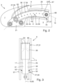
- Fig. 2 shows the wing 1 from Fig. 1 in more detail.
- the wing 1 comprises a main wing 5, a slat 7, and a connection assembly 9 movable connecting the slat 7 to the main wing 5, such that the slat 7 is movable between a retracted position 11 and at least one extended position 13, 15.
- the connection assembly 9 comprises an elongate slat track 17 that extends along a track longitudinal axis 19 between a front end 21 and a rear end 23 and has an intermediate portion 25 between the front and rear ends 21, 23.
- the front end 21 of the slat track 17 is fixedly mounted to the slat 7.
- the rear end 23 and the intermediate portion 25 of the slat track 17 are movably mounted to the main wing 5 by a roller bearing 27 such that the slat track 17 is movable along the track longitudinal axis 19.
- the roller bearing 27 comprises a guide rail 29 fixedly mounted to the main wing 5 and a first roller unit 31 fixedly mounted to the rear end 23 of the slat track 17 and engaging the guide rail 29.
- the roller bearing 27 comprises a second roller unit 33 that is fixedly mounted to the main wing 5 and that engages an engagement surface 35 provided at the intermediate portion 25 of the slat track 17.
- the slat track 17 has a double-C-shaped profile 37 comprising an upper flange portion 39, a lower flange portion 41 and at least one web portion 43 connecting upper and lower flange portions 39, 41.
- the second roller unit 33 is arranged in a recess 45 between upper and lower flange portions 39, 41 and engages the engagement surface 35 provided at the upper flange portion 39 and at the lower flange portion 41.
- the double-C-shaped profile 37 of the slat track 17 provides that a first recess 45a is formed between the upper and lower flange portions 39, 41 at a first side 47 of the web portion 43, and a second recess 45b is formed between the upper and lower flange portions 39, 41 at a second side 49 of the web portion 43 opposite the first side 47.
- the second roller unit 33 comprises a first roller element 51 and a second roller element 53.
- the first roller element 51 is arranged in the first recess 45a and the second roller element 53 is arranged in the second recess 45b.
- First and second roller elements 51, 53 are arranged coaxially and have the same radius.
- the first roller element 51 is mounted on a first shaft 55 and the second roller element 53 is mounted on a second shaft 57 separate from the first shaft 55.
- First and second shafts 55, 57 are independently supported at the main wing 5.
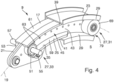
- Figs. 3-5 show that the slat track 17 comprises a first track part 59 and a second track part 61 that are formed separate from one another.
- Each of the first and second track parts 59, 61 is formed integrally and extends along the track longitudinal axis 19 from the rear end 23 to the front end 21.
- the first and second track parts 59, 61 are mounted to one another by bolts 63 and rest against one another along a contact plane 65 spanned by the track longitudinal axis 19 and a wing thickness direction 67.
- the first roller unit 31 comprises a third roller element 69 and a fourth roller element 71.
- Third and fourth roller elements 69, 71 are arranged coaxially and have the same radius.
- the third roller element 69 is mounted to the first track part 59 and the fourth roller element 71 is mounted to the second track part 61.
- the first roller unit 31 might also comprise only a single third roller element 69.
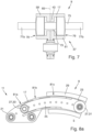
- Figs. 6 and 7 show an alternative to the separate first and second shafts 55, 57 that are independently supported at the main wing 5.
- the web portion 43 of the slat track 17 comprises a slot 73 extending from the first side 47 to the second side 49 of the web portion 43 and extending elongated along the track longitudinal axis 19.
- the first roller element 51 and the second roller element 53 are mounted on one common shaft 75 for common rotation.
- the common shaft 75 proceeds through the slot 73 from the first side 47 to the second side 49 of the web portion 43.
- Opposite ends 77a, 77b of the common shaft 75 are supported at the main wing 5.
- Fig. 8 shows an embodiment, where the distance between the upper flange portion 39 and the lower flange portion 41 of the slat track 17 is larger than a diameter of the second roller unit 33, such that a clearance 79 is provided either between the second roller unit 33 and the engagement surface 35 at the upper flange portion 39, or between the second roller unit 33 and the engagement surface 35 at the lower flange portion 41.
- the clearance 79 is smaller at gated locations 81a, 81b, 81c along the slat track 17 where the second roller unit 33 is located when the slat 7 is in the retracted position 11 ( Fig. 8a ), in a partly extended position 13 ( Fig. 8b ) and in a fully extended position 15 ( Fig. 8c ).
- the clearance 79 is larger in areas between the gated locations 81a, 81b, 81c.
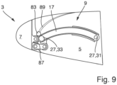
- roller bearing 27 comprises a third roller unit 83 mounted to the main wing 5 and engaging an upper surface 85 of the upper flange portion 39 of the slat track 17.
- the third roller unit 83 comprises one common roller element engaging both first and second track parts 59, 61.
- the third roller unit 83 is arranged proximate a leading edge 87 of the main wing 5 and partly outside the main wing 5 with respect to an outer skin profile line 89 of the main wing 5.
- connection assembly 9 is a first connection assembly 91
- the wing 3 comprises a second connection assembly 93 connecting the slat 7 to the main wing 5 in a position spaced apart from the first connection assembly 91 in a wing span direction 95, and wherein the second connection assembly 93 is formed as the first connection assembly 91.
Landscapes
- Engineering & Computer Science (AREA)
- Aviation & Aerospace Engineering (AREA)
- Mechanical Engineering (AREA)
- Automation & Control Theory (AREA)
- Blinds (AREA)
- Operating, Guiding And Securing Of Roll- Type Closing Members (AREA)
- Structures Of Non-Positive Displacement Pumps (AREA)
Claims (15)
- Flügel (3) für ein Flugzeug (1), umfassend:einen Hauptflügel (5),einen Vorflügel (7), undeine Verbindungsanordnung (9), die den Vorflügel (7) bewegbar mit dem Hauptflügel (5) verbindet, sodass der Vorflügel (7) zwischen einer eingezogenen Position (11) und zumindest einer ausgezogenen Position (13, 15) bewegbar ist,wobei die Verbindungsanordnung (9) eine längliche Vorflügelschiene (17) umfasst, die sich entlang einer Schienenlängsachse (19) zwischen einem vorderen Ende (21) und einem hinteren Ende (23) erstreckt und einen Zwischenteil (25) zwischen dem vorderen und dem hinteren Ende (21, 23) aufweist,wobei das vordere Ende (21) der Vorflügelschiene (17) am Vorflügel (7) montiert ist,wobei das hintere Ende (23) und der Zwischenteil (25) der Vorflügelschiene (17) über ein Rollenlager (27) am Hauptflügel (5) montiert sind, sodass die Vorflügelschiene (17) entlang der Schienenlängsachse (19) bewegbar ist,wobei das Rollenlager (27) eine am Hauptflügel (5) montierte Führungsschiene (29) und eine am hinteren Ende (23) der Vorflügelschiene (17) montierte und in die Führungsschiene (29) eingreifende erste Rolleneinheit (31) umfasst,wobei das Rollenlager (27) eine zweite Rolleneinheit (33) umfasst, die am Hauptflügel (5) montiert ist und die in Eingriff mit einer am Zwischenteil (25) der Vorflügelschiene (17) bereitgestellten Eingriffsoberfläche (35) kommt,wobei die Vorflügelschiene (17) ein Profil (37) aufweist, das einen oberen Flanschteil (39), einen unteren Flanschteil (41) und zumindest einen Versteifungsteil (43), der den oberen und den unteren Flanschteil (39, 41) verbindet, umfasst, undwobei die zweite Rolleneinheit (33) in einer Vertiefung (45) zwischen dem oberen und dem unteren Flanschteil (39, 41) angeordnet ist und mit der Eingriffsoberfläche (35), die am oberen Flanschteil (39) und/oder am unteren Flanschteil (41) bereitgestellt ist, in Eingriff kommt.
- Flügel nach Anspruch 1, wobei die Vorflügelschiene (17) ein solches Profil (37) aufweist, dass eine erste Vertiefung (45a) zwischen dem oberen und dem unteren Flanschteil (39, 41) auf einer ersten Seite (47) des Versteifungsteils (43) gebildet ist, und eine zweite Vertiefung (45b) zwischen dem oberen und dem unteren Flanschteil (39, 41) auf einer zweiten Seite (49) des Versteifungsteils (43) gegenüber der ersten Seite (47) gebildet ist.
- Flügel nach Anspruch 2, wobei die zweite Rolleneinheit (33) ein erstes Rollenelement (51) und ein zweites Rollenelement (53) umfasst,wobei das erste Rollenelement (51) in der ersten Vertiefung (45a) angeordnet ist und das zweite Rollenelement (53) in der zweiten Vertiefung (45b) angeordnet ist, undwobei erste und zweite Rollenelemente (51, 53) koaxial angeordnet sind und den gleichen Radius aufweisen.
- Flügel nach Anspruch 3, wobei der Versteifungsteil (43) der Vorflügelschiene (17) einen Schlitz (73) umfasst, der sich von der ersten Seite (47) zur zweiten Seite (49) des Versteifungsteils (43) erstreckt und sich länglich entlang der Schienenlängsachse (19) erstreckt, wobei das erste Rollenelement (51) und das zweite Rollenelement (53) für gemeinsame Rotation auf einer gemeinsamen Welle (75) montiert sind, und
wobei die gemeinsame Welle (75) durch den Schlitz (73) von der ersten Seite (47) zur zweiten Seite (49) des Versteifungsteils (43) verläuft. - Flügel nach Anspruch 3, wobei das erste Rollenelement (51) auf einer ersten Welle (55) montiert ist und das zweite Rollenelement (53) auf einer zweiten Welle (57) montiert ist, die separat von der ersten Welle (55) ist.
- Flügel nach einem der Ansprüche 1 bis 5, wobei die erste Rolleneinheit (31) ein einzelnes drittes Rollenelement (69) umfasst.
- Flügel nach einem der Ansprüche 1 bis 5, wobei die erste Rolleneinheit (31) ein drittes Rollenelement (69) und ein viertes Rollenelement (71) umfasst,
wobei dritte und vierte Rollenelemente (69, 71) koaxial angeordnet sind und den gleichen Radius aufweisen. - Flügel nach einem der Ansprüche 1 bis 7, wobei die Vorflügelschiene (17) einen ersten Schienenteil (59) und einen zweiten Schienenteil (61) umfasst, die separat voneinander gebildet sind,wobei jedes aus dem ersten und dem zweiten Schienenteil (59, 61) integral ausgebildet ist und sich entlang der Schienenlängsachse (19) vom hinteren Ende (23) zum vorderen Ende (21) erstreckt, undwobei der erste und der zweite Schienenteil (59, 61) aneinander montiert sind und entlang einer Kontaktebene (65), die durch die Schienenlängsachse (19) und eine Flügeldickenrichtung (67) aufgespannt ist, aneinander anliegen.
- Flügel nach Anspruch 8, wenn abhängig von Anspruch 6, wobei das dritte Rollenelement (69) sowohl am ersten Schienenteil (59) als auch am zweiten Schienenteil (61) montiert ist.
- Flügel nach Anspruch 8, wenn abhängig von Anspruch 7, wobei das dritte Rollenelement (69) am ersten Schienenteil (59) montiert ist und das vierte Rollenelement (71) am zweiten Schienenteil (61) montiert ist.
- Flügel nach einem der Ansprüche 1 bis 10, wobei ein Abstand zwischen dem oberen Flanschteil (39) und dem unteren Flanschteil (41) der Vorflügelschiene (17) größer als ein Durchmesser der zweiten Rolleneinheit (33) ist, sodass ein Abstand (79) entweder zwischen der zweiten Rolleneinheit (33) und der Eingriffsoberfläche (35) am oberen Flanschteil (39) oder zwischen der zweiten Rolleneinheit (33) und der Eingriffsoberfläche (35) am unteren Flanschteil (41) bereitgestellt wird,wobei der Abstand (79) an eingefassten Orten (81a, 81b, 81c) entlang der Vorflügelschiene (17) kleiner ist, wo sich die zweite Rolleneinheit (33) befindet, wenn der Vorflügel (7) in der eingezogenen Position (11) und/oder in einer vollständig ausgezogenen Position (15) und/oder in einer definierten teilweise ausgezogenen Position (13) ist, undwobei der Abstand (79) größer in Bereichen zwischen den eingefassten Orten (81a, 81b, 81c) ist.
- Flügel nach einem der Ansprüche 1 bis 11, wobei das Rollenlager (27) eine dritte Rolleneinheit (83) umfasst, die am Hauptflügel (5) montiert ist und in Eingriff mit einer oberen Oberfläche (85) des oberen Flanschteils (39) der Vorflügelschiene (17) kommt.
- Flügel nach einem der Ansprüche 1 bis 12, wobei die Verbindungsanordnung (9) eine erste Verbindungsanordnung (91) ist, wobei der Flügel (3) eine zweite Verbindungsanordnung (93) umfasst, die den Vorflügel (7) mit dem Hauptflügel (5) in einer Position verbindet, die von der ersten Verbindungsanordnung (91) in einer Flügelspannweitenrichtung (95) beabstandet ist, und wobei die zweite Verbindungsanordnung (93) wie die erste Verbindungsanordnung (91) gebildet ist.
- Flugzeug (1), umfassend einen Flügel (3) nach einem der Ansprüche 1 bis 13.
- Verbindungsanordnung (9) zum bewegbaren Verbinden eines Vorflügels (7) mit einem Hauptflügel (5) für ein Flugzeug (1), wobei die Verbindungsanordnung (9) Folgendes umfasst:eine längliche Vorflügelschiene (17), die sich entlang einer Schienenlängsachse (19) zwischen einem vorderen Ende (21) und einem hinteren Ende (23) erstreckt und einen Zwischenteil (25) zwischen dem vorderen und dem hinteren Ende (21, 23) aufweist, undein Rollenlager (27),wobei das vordere Ende (21) der Vorflügelschiene (17) dazu ausgelegt ist, am Vorflügel (7) montiert zu werden, wobei das hintere Ende (23) und der Zwischenteil (25) der Vorflügelschiene (17) dazu ausgelegt sind, über das Rollenlager (27) am Hauptflügel (5) montiert zu werden, sodass die Vorflügelschiene (17) entlang der Schienenlängsachse (19) bewegbar ist,wobei das Rollenlager (27) eine Führungsschiene (29), dazu ausgelegt, am Hauptflügel (5) montiert zu werden, und eine erste Rolleneinheit (31), die am hinteren Ende (23) der Vorflügelschiene (17) montiert ist und dazu ausgelegt ist, mit der Führungsschiene (29) in Eingriff zu kommen, umfasst, undwobei das Rollenlager (27) eine zweite Rolleneinheit (33) umfasst, die dazu ausgelegt ist, am Hauptflügel (5) montiert zu werden und die dazu ausgelegt ist, in Eingriff mit einer am Zwischenteil (25) der Vorflügelschiene (17) bereitgestellten Eingriffsoberfläche (35) zu kommen,wobei die Vorflügelschiene (17) ein Profil (37) aufweist, das einen oberen Flanschteil (39), einen unteren Flanschteil (41) und zumindest einen Versteifungsteil (43), der den oberen und den unteren Flanschteil (39, 41) verbindet, umfasst, undwobei die zweite Rolleneinheit (33) dazu ausgelegt ist, in einer Vertiefung (45) zwischen dem oberen und dem unteren Flanschteil (39, 41) angeordnet zu werden und mit der Eingriffsoberfläche (35), die am oberen Flanschteil (39) und/oder am unteren Flanschteil (41) bereitgestellt ist, in Eingriff zu kommen.
Applications Claiming Priority (3)
| Application Number | Priority Date | Filing Date | Title |
|---|---|---|---|
| DE102017004090 | 2017-04-28 | ||
| DE102017123701 | 2017-10-11 | ||
| PCT/EP2018/060809 WO2018197649A1 (en) | 2017-04-28 | 2018-04-26 | Wing for an aircraft |
Publications (2)
| Publication Number | Publication Date |
|---|---|
| EP3615422A1 EP3615422A1 (de) | 2020-03-04 |
| EP3615422B1 true EP3615422B1 (de) | 2024-10-30 |
Family
ID=62091878
Family Applications (1)
| Application Number | Title | Priority Date | Filing Date |
|---|---|---|---|
| EP18721349.1A Active EP3615422B1 (de) | 2017-04-28 | 2018-04-26 | Flügel für ein flugzeug |
Country Status (6)
| Country | Link |
|---|---|
| US (2) | US11186356B2 (de) |
| EP (1) | EP3615422B1 (de) |
| JP (1) | JP6915088B2 (de) |
| CN (1) | CN110546065B (de) |
| RU (1) | RU2746479C1 (de) |
| WO (1) | WO2018197649A1 (de) |
Families Citing this family (21)
| Publication number | Priority date | Publication date | Assignee | Title |
|---|---|---|---|---|
| EP3615422B1 (de) | 2017-04-28 | 2024-10-30 | Airbus Operations GmbH | Flügel für ein flugzeug |
| EP3501977B1 (de) * | 2017-12-19 | 2021-08-11 | Asco Industries NV | Freisetzungssystem für eine hochauftriebsvorrichtung einer tragflächenvorderkante |
| US11845550B2 (en) | 2019-02-28 | 2023-12-19 | Airbus Operations Gmbh | Wing leading-edge device and a wing having such a wing leading-edge device |
| EP3718881B1 (de) | 2019-03-29 | 2022-10-12 | Airbus Operations GmbH | Flügel für ein flugzeug |
| EP3969361B1 (de) * | 2019-07-12 | 2025-12-31 | Airbus Operations GmbH | Verbindungseinrichtung für einen vorflügel einer luftfahrzeugtragfläche |
| US11420727B2 (en) | 2019-07-25 | 2022-08-23 | Airbus Operations Gmbh | Airfoil arrangement for an aircraft |
| WO2021037981A1 (en) * | 2019-08-30 | 2021-03-04 | Airbus Operations Gmbh | Leading edge assembly, wing, and aircraft |
| EP3878734B1 (de) | 2020-03-11 | 2023-07-19 | Airbus Operations GmbH | Führungselement für eine hochauftriebsprofilanordnung eines flugzeugs, hochauftriebsprofilanordnung und herstellungsverfahren |
| US11731753B2 (en) * | 2020-03-24 | 2023-08-22 | Airbus Operations Gmbh | Wing for an aircraft |
| EP4032804B1 (de) * | 2021-01-22 | 2024-08-28 | Airbus Operations GmbH | Flügel für ein flugzeug |
| EP4032801B1 (de) * | 2021-01-22 | 2024-08-28 | Airbus Operations GmbH | Flügel für ein flugzeug |
| US11897613B2 (en) * | 2021-06-08 | 2024-02-13 | Airbus Operations Gmbh | Wing for an aircraft |
| EP4112450A1 (de) * | 2021-06-30 | 2023-01-04 | Airbus Operations GmbH | Flügel für ein flugzeug |
| EP4303123A1 (de) | 2022-07-07 | 2024-01-10 | Airbus Operations GmbH | Flügel für ein flugzeug |
| EP4424590A1 (de) * | 2023-02-28 | 2024-09-04 | Airbus Operations GmbH | Flügel für ein flugzeug |
| EP4424592A1 (de) | 2023-02-28 | 2024-09-04 | Airbus Operations GmbH | Flügel für ein flugzeug |
| US12448109B2 (en) * | 2023-05-05 | 2025-10-21 | The Boeing Company | Auxiliary flap assembly for aircraft |
| US12509213B2 (en) * | 2023-05-17 | 2025-12-30 | The Boeing Company | Auxiliary flap assembly |
| EP4477531A1 (de) | 2023-06-14 | 2024-12-18 | Airbus Operations GmbH | Flügel für ein flugzeug |
| EP4491508A1 (de) | 2023-07-12 | 2025-01-15 | Airbus Operations GmbH | Flügel für ein flugzeug |
| EP4491509A1 (de) * | 2023-07-12 | 2025-01-15 | Airbus Operations GmbH | Flügel für ein flugzeug |
Family Cites Families (26)
| Publication number | Priority date | Publication date | Assignee | Title |
|---|---|---|---|---|
| GB298508A (en) * | 1927-07-09 | 1928-10-09 | Frederick Handley Page | Improvements in means for controlling aeroplanes |
| GB404149A (en) | 1933-02-02 | 1934-01-11 | Fairey Aviat Co Ltd | Improvements in or relating to aerofoil surfaces |
| US2938680A (en) * | 1957-07-02 | 1960-05-31 | North American Aviation Inc | Multiple position airfoil slat |
| US3272458A (en) | 1964-12-08 | 1966-09-13 | Gen Dynamics Corp | Means for positioning a rotating wing slat device |
| FR2231564B1 (de) * | 1973-05-29 | 1976-11-12 | Dassault Avions | |
| GB1492177A (en) * | 1975-10-08 | 1977-11-16 | British Aircraft Corp Ltd | Aircraft lift-producing members |
| US4360176A (en) * | 1979-11-05 | 1982-11-23 | The Boeing Company | Wing leading edge slat |
| US4471928A (en) * | 1980-08-13 | 1984-09-18 | The Boeing Company | Extendible airfoil track assembly |
| US4753402A (en) * | 1985-12-30 | 1988-06-28 | The Boeing Company | Biased leading edge slat apparatus |
| GB2204538B (en) | 1987-05-06 | 1990-12-12 | British Aerospace | Wing leading edge arrangements for aircraft |
| US5039032A (en) | 1988-11-07 | 1991-08-13 | The Boeing Company | High taper wing tip extension |
| US5544847A (en) * | 1993-11-10 | 1996-08-13 | The Boeing Company | Leading edge slat/wing combination |
| US20070102587A1 (en) * | 2005-11-07 | 2007-05-10 | The Boeing Company | Wing leading edge slat system |
| GB0805599D0 (en) * | 2008-03-28 | 2008-04-30 | Airbus Uk Ltd | Slat deployment mechanism |
| BE1018114A5 (fr) * | 2008-05-06 | 2010-05-04 | Sonaca Sociutu Anonyme | Aile d'aeronef comprenant un volet mobile de bord d'attaque equipe d'un rail suiveur contraint en deplacement selon une trajectoire en arc de cercle |
| GB0810460D0 (en) * | 2008-06-09 | 2008-07-09 | Airbus Uk Ltd | Support assembly |
| GB0810724D0 (en) * | 2008-06-12 | 2008-07-16 | Airbus Uk Ltd | Slat assembly |
| GB0816022D0 (en) | 2008-09-03 | 2008-10-08 | Airbus Uk Ltd | Slat support assembly |
| ES2427390T3 (es) | 2009-10-29 | 2013-10-30 | Asco Industries | Carril de guiado para dispositivo hipersustentador |
| FR3011226B1 (fr) | 2013-09-30 | 2017-05-19 | Airbus Operations Sas | Systeme de volet de bord de fuite hypersustentateur pour voilure d'aeronef. |
| EP3527488B1 (de) | 2015-12-04 | 2021-03-03 | Roller Bearing Company of America, Inc. | Wälzlager mit einteiligen inneren und äusseren laufringen sowie rollelementen |
| US10053237B2 (en) * | 2016-05-20 | 2018-08-21 | The Boeing Company | Track roller failure detection systems and methods |
| EP3395678B1 (de) * | 2017-04-26 | 2021-05-26 | Asco Industries NV | Führungsanordnung für eine hochauftriebsvorrichtungsträgerbahn einer tragflächenvorderkante |
| RU2752205C2 (ru) | 2017-04-28 | 2021-07-23 | Эйрбас Оперейшнз Гмбх | Консоль крыла для летательного аппарата |
| EP3615422B1 (de) | 2017-04-28 | 2024-10-30 | Airbus Operations GmbH | Flügel für ein flugzeug |
| US11312473B2 (en) * | 2019-05-30 | 2022-04-26 | The Boeing Company | Aircraft slat aero-restoration seal door and method therefor |
-
2018
- 2018-04-26 EP EP18721349.1A patent/EP3615422B1/de active Active
- 2018-04-26 CN CN201880027574.4A patent/CN110546065B/zh active Active
- 2018-04-26 JP JP2019558586A patent/JP6915088B2/ja active Active
- 2018-04-26 RU RU2019138316A patent/RU2746479C1/ru active
- 2018-04-26 WO PCT/EP2018/060809 patent/WO2018197649A1/en not_active Ceased
-
2019
- 2019-10-25 US US16/664,197 patent/US11186356B2/en active Active
-
2021
- 2021-11-23 US US17/533,652 patent/US11565789B2/en active Active
Also Published As
| Publication number | Publication date |
|---|---|
| JP6915088B2 (ja) | 2021-08-04 |
| US20200122819A1 (en) | 2020-04-23 |
| US20220081100A1 (en) | 2022-03-17 |
| EP3615422A1 (de) | 2020-03-04 |
| RU2746479C1 (ru) | 2021-04-14 |
| US11565789B2 (en) | 2023-01-31 |
| WO2018197649A1 (en) | 2018-11-01 |
| BR112019022079A2 (pt) | 2020-05-05 |
| CN110546065A (zh) | 2019-12-06 |
| US11186356B2 (en) | 2021-11-30 |
| CN110546065B (zh) | 2023-09-05 |
| JP2020517521A (ja) | 2020-06-18 |
Similar Documents
| Publication | Publication Date | Title |
|---|---|---|
| EP3615422B1 (de) | Flügel für ein flugzeug | |
| US11214355B2 (en) | Wing for an aircraft | |
| EP4101754B1 (de) | Flügel für ein flugzeug | |
| EP3718881B1 (de) | Flügel für ein flugzeug | |
| CN103448906A (zh) | 缝翼支撑组件 | |
| US11034433B2 (en) | Wing for an aircraft | |
| EP4032804A1 (de) | Flügel für ein flugzeug | |
| US12539959B2 (en) | Wing for an aircraft with a slat assembly | |
| US12054258B2 (en) | Wing for an aircraft and connecting assembly to movably connect a slat to a main wing | |
| US12441459B2 (en) | Wing for an aircraft including a high lift body track with roller unit | |
| US12583575B2 (en) | Wing for an aircraft | |
| US20250019063A1 (en) | Wing For An Aircraft | |
| EP4032801B1 (de) | Flügel für ein flugzeug | |
| US12391361B2 (en) | Wing for an aircraft |
Legal Events
| Date | Code | Title | Description |
|---|---|---|---|
| STAA | Information on the status of an ep patent application or granted ep patent |
Free format text: STATUS: UNKNOWN |
|
| STAA | Information on the status of an ep patent application or granted ep patent |
Free format text: STATUS: THE INTERNATIONAL PUBLICATION HAS BEEN MADE |
|
| PUAI | Public reference made under article 153(3) epc to a published international application that has entered the european phase |
Free format text: ORIGINAL CODE: 0009012 |
|
| STAA | Information on the status of an ep patent application or granted ep patent |
Free format text: STATUS: REQUEST FOR EXAMINATION WAS MADE |
|
| 17P | Request for examination filed |
Effective date: 20191120 |
|
| AK | Designated contracting states |
Kind code of ref document: A1 Designated state(s): AL AT BE BG CH CY CZ DE DK EE ES FI FR GB GR HR HU IE IS IT LI LT LU LV MC MK MT NL NO PL PT RO RS SE SI SK SM TR |
|
| AX | Request for extension of the european patent |
Extension state: BA ME |
|
| DAV | Request for validation of the european patent (deleted) | ||
| DAX | Request for extension of the european patent (deleted) | ||
| STAA | Information on the status of an ep patent application or granted ep patent |
Free format text: STATUS: EXAMINATION IS IN PROGRESS |
|
| 17Q | First examination report despatched |
Effective date: 20201127 |
|
| GRAP | Despatch of communication of intention to grant a patent |
Free format text: ORIGINAL CODE: EPIDOSNIGR1 |
|
| STAA | Information on the status of an ep patent application or granted ep patent |
Free format text: STATUS: GRANT OF PATENT IS INTENDED |
|
| INTG | Intention to grant announced |
Effective date: 20221221 |
|
| GRAJ | Information related to disapproval of communication of intention to grant by the applicant or resumption of examination proceedings by the epo deleted |
Free format text: ORIGINAL CODE: EPIDOSDIGR1 |
|
| STAA | Information on the status of an ep patent application or granted ep patent |
Free format text: STATUS: EXAMINATION IS IN PROGRESS |
|
| INTC | Intention to grant announced (deleted) | ||
| GRAP | Despatch of communication of intention to grant a patent |
Free format text: ORIGINAL CODE: EPIDOSNIGR1 |
|
| STAA | Information on the status of an ep patent application or granted ep patent |
Free format text: STATUS: GRANT OF PATENT IS INTENDED |
|
| RIC1 | Information provided on ipc code assigned before grant |
Ipc: B64C 9/22 20060101AFI20240508BHEP |
|
| INTG | Intention to grant announced |
Effective date: 20240522 |
|
| GRAS | Grant fee paid |
Free format text: ORIGINAL CODE: EPIDOSNIGR3 |
|
| GRAA | (expected) grant |
Free format text: ORIGINAL CODE: 0009210 |
|
| STAA | Information on the status of an ep patent application or granted ep patent |
Free format text: STATUS: THE PATENT HAS BEEN GRANTED |
|
| AK | Designated contracting states |
Kind code of ref document: B1 Designated state(s): AL AT BE BG CH CY CZ DE DK EE ES FI FR GB GR HR HU IE IS IT LI LT LU LV MC MK MT NL NO PL PT RO RS SE SI SK SM TR |
|
| REG | Reference to a national code |
Ref country code: GB Ref legal event code: FG4D |
|
| REG | Reference to a national code |
Ref country code: CH Ref legal event code: EP |
|
| REG | Reference to a national code |
Ref country code: DE Ref legal event code: R096 Ref document number: 602018075956 Country of ref document: DE |
|
| REG | Reference to a national code |
Ref country code: IE Ref legal event code: FG4D |
|
| REG | Reference to a national code |
Ref country code: LT Ref legal event code: MG9D |
|
| REG | Reference to a national code |
Ref country code: NL Ref legal event code: MP Effective date: 20241030 |
|
| PG25 | Lapsed in a contracting state [announced via postgrant information from national office to epo] |
Ref country code: IS Free format text: LAPSE BECAUSE OF FAILURE TO SUBMIT A TRANSLATION OF THE DESCRIPTION OR TO PAY THE FEE WITHIN THE PRESCRIBED TIME-LIMIT Effective date: 20250228 Ref country code: PT Free format text: LAPSE BECAUSE OF FAILURE TO SUBMIT A TRANSLATION OF THE DESCRIPTION OR TO PAY THE FEE WITHIN THE PRESCRIBED TIME-LIMIT Effective date: 20250228 Ref country code: HR Free format text: LAPSE BECAUSE OF FAILURE TO SUBMIT A TRANSLATION OF THE DESCRIPTION OR TO PAY THE FEE WITHIN THE PRESCRIBED TIME-LIMIT Effective date: 20241030 |
|
| PG25 | Lapsed in a contracting state [announced via postgrant information from national office to epo] |
Ref country code: FI Free format text: LAPSE BECAUSE OF FAILURE TO SUBMIT A TRANSLATION OF THE DESCRIPTION OR TO PAY THE FEE WITHIN THE PRESCRIBED TIME-LIMIT Effective date: 20241030 Ref country code: NL Free format text: LAPSE BECAUSE OF FAILURE TO SUBMIT A TRANSLATION OF THE DESCRIPTION OR TO PAY THE FEE WITHIN THE PRESCRIBED TIME-LIMIT Effective date: 20241030 |
|
| REG | Reference to a national code |
Ref country code: AT Ref legal event code: MK05 Ref document number: 1736666 Country of ref document: AT Kind code of ref document: T Effective date: 20241030 |
|
| PG25 | Lapsed in a contracting state [announced via postgrant information from national office to epo] |
Ref country code: BG Free format text: LAPSE BECAUSE OF FAILURE TO SUBMIT A TRANSLATION OF THE DESCRIPTION OR TO PAY THE FEE WITHIN THE PRESCRIBED TIME-LIMIT Effective date: 20241030 |
|
| PG25 | Lapsed in a contracting state [announced via postgrant information from national office to epo] |
Ref country code: ES Free format text: LAPSE BECAUSE OF FAILURE TO SUBMIT A TRANSLATION OF THE DESCRIPTION OR TO PAY THE FEE WITHIN THE PRESCRIBED TIME-LIMIT Effective date: 20241030 |
|
| PG25 | Lapsed in a contracting state [announced via postgrant information from national office to epo] |
Ref country code: NO Free format text: LAPSE BECAUSE OF FAILURE TO SUBMIT A TRANSLATION OF THE DESCRIPTION OR TO PAY THE FEE WITHIN THE PRESCRIBED TIME-LIMIT Effective date: 20250130 |
|
| PG25 | Lapsed in a contracting state [announced via postgrant information from national office to epo] |
Ref country code: LV Free format text: LAPSE BECAUSE OF FAILURE TO SUBMIT A TRANSLATION OF THE DESCRIPTION OR TO PAY THE FEE WITHIN THE PRESCRIBED TIME-LIMIT Effective date: 20241030 Ref country code: GR Free format text: LAPSE BECAUSE OF FAILURE TO SUBMIT A TRANSLATION OF THE DESCRIPTION OR TO PAY THE FEE WITHIN THE PRESCRIBED TIME-LIMIT Effective date: 20250131 Ref country code: AT Free format text: LAPSE BECAUSE OF FAILURE TO SUBMIT A TRANSLATION OF THE DESCRIPTION OR TO PAY THE FEE WITHIN THE PRESCRIBED TIME-LIMIT Effective date: 20241030 |
|
| PG25 | Lapsed in a contracting state [announced via postgrant information from national office to epo] |
Ref country code: PL Free format text: LAPSE BECAUSE OF FAILURE TO SUBMIT A TRANSLATION OF THE DESCRIPTION OR TO PAY THE FEE WITHIN THE PRESCRIBED TIME-LIMIT Effective date: 20241030 |
|
| PG25 | Lapsed in a contracting state [announced via postgrant information from national office to epo] |
Ref country code: RS Free format text: LAPSE BECAUSE OF FAILURE TO SUBMIT A TRANSLATION OF THE DESCRIPTION OR TO PAY THE FEE WITHIN THE PRESCRIBED TIME-LIMIT Effective date: 20250130 |
|
| PG25 | Lapsed in a contracting state [announced via postgrant information from national office to epo] |
Ref country code: SM Free format text: LAPSE BECAUSE OF FAILURE TO SUBMIT A TRANSLATION OF THE DESCRIPTION OR TO PAY THE FEE WITHIN THE PRESCRIBED TIME-LIMIT Effective date: 20241030 |
|
| PGFP | Annual fee paid to national office [announced via postgrant information from national office to epo] |
Ref country code: DE Payment date: 20250422 Year of fee payment: 8 |
|
| PG25 | Lapsed in a contracting state [announced via postgrant information from national office to epo] |
Ref country code: DK Free format text: LAPSE BECAUSE OF FAILURE TO SUBMIT A TRANSLATION OF THE DESCRIPTION OR TO PAY THE FEE WITHIN THE PRESCRIBED TIME-LIMIT Effective date: 20241030 |
|
| PGFP | Annual fee paid to national office [announced via postgrant information from national office to epo] |
Ref country code: GB Payment date: 20250423 Year of fee payment: 8 |
|
| PGFP | Annual fee paid to national office [announced via postgrant information from national office to epo] |
Ref country code: BE Payment date: 20250418 Year of fee payment: 8 |
|
| PG25 | Lapsed in a contracting state [announced via postgrant information from national office to epo] |
Ref country code: EE Free format text: LAPSE BECAUSE OF FAILURE TO SUBMIT A TRANSLATION OF THE DESCRIPTION OR TO PAY THE FEE WITHIN THE PRESCRIBED TIME-LIMIT Effective date: 20241030 |
|
| PGFP | Annual fee paid to national office [announced via postgrant information from national office to epo] |
Ref country code: FR Payment date: 20250425 Year of fee payment: 8 |
|
| PG25 | Lapsed in a contracting state [announced via postgrant information from national office to epo] |
Ref country code: RO Free format text: LAPSE BECAUSE OF FAILURE TO SUBMIT A TRANSLATION OF THE DESCRIPTION OR TO PAY THE FEE WITHIN THE PRESCRIBED TIME-LIMIT Effective date: 20241030 |
|
| PG25 | Lapsed in a contracting state [announced via postgrant information from national office to epo] |
Ref country code: SK Free format text: LAPSE BECAUSE OF FAILURE TO SUBMIT A TRANSLATION OF THE DESCRIPTION OR TO PAY THE FEE WITHIN THE PRESCRIBED TIME-LIMIT Effective date: 20241030 |
|
| PG25 | Lapsed in a contracting state [announced via postgrant information from national office to epo] |
Ref country code: CZ Free format text: LAPSE BECAUSE OF FAILURE TO SUBMIT A TRANSLATION OF THE DESCRIPTION OR TO PAY THE FEE WITHIN THE PRESCRIBED TIME-LIMIT Effective date: 20241030 |
|
| PG25 | Lapsed in a contracting state [announced via postgrant information from national office to epo] |
Ref country code: IT Free format text: LAPSE BECAUSE OF FAILURE TO SUBMIT A TRANSLATION OF THE DESCRIPTION OR TO PAY THE FEE WITHIN THE PRESCRIBED TIME-LIMIT Effective date: 20241030 |
|
| REG | Reference to a national code |
Ref country code: DE Ref legal event code: R097 Ref document number: 602018075956 Country of ref document: DE |
|
| PLBE | No opposition filed within time limit |
Free format text: ORIGINAL CODE: 0009261 |
|
| STAA | Information on the status of an ep patent application or granted ep patent |
Free format text: STATUS: NO OPPOSITION FILED WITHIN TIME LIMIT |
|
| PG25 | Lapsed in a contracting state [announced via postgrant information from national office to epo] |
Ref country code: SE Free format text: LAPSE BECAUSE OF FAILURE TO SUBMIT A TRANSLATION OF THE DESCRIPTION OR TO PAY THE FEE WITHIN THE PRESCRIBED TIME-LIMIT Effective date: 20241030 |
|
| 26N | No opposition filed |
Effective date: 20250731 |
|
| REG | Reference to a national code |
Ref country code: CH Ref legal event code: H13 Free format text: ST27 STATUS EVENT CODE: U-0-0-H10-H13 (AS PROVIDED BY THE NATIONAL OFFICE) Effective date: 20251125 |
|
| PG25 | Lapsed in a contracting state [announced via postgrant information from national office to epo] |
Ref country code: LU Free format text: LAPSE BECAUSE OF NON-PAYMENT OF DUE FEES Effective date: 20250426 |
|
| PG25 | Lapsed in a contracting state [announced via postgrant information from national office to epo] |
Ref country code: MC Free format text: LAPSE BECAUSE OF FAILURE TO SUBMIT A TRANSLATION OF THE DESCRIPTION OR TO PAY THE FEE WITHIN THE PRESCRIBED TIME-LIMIT Effective date: 20241030 |
|
| PG25 | Lapsed in a contracting state [announced via postgrant information from national office to epo] |
Ref country code: CH Free format text: LAPSE BECAUSE OF NON-PAYMENT OF DUE FEES Effective date: 20250430 |
|
| PG25 | Lapsed in a contracting state [announced via postgrant information from national office to epo] |
Ref country code: IE Free format text: LAPSE BECAUSE OF NON-PAYMENT OF DUE FEES Effective date: 20250426 |