EP3614539B1 - Busbar, motor, and power transmission system using same - Google Patents
Busbar, motor, and power transmission system using same Download PDFInfo
- Publication number
- EP3614539B1 EP3614539B1 EP19199593.5A EP19199593A EP3614539B1 EP 3614539 B1 EP3614539 B1 EP 3614539B1 EP 19199593 A EP19199593 A EP 19199593A EP 3614539 B1 EP3614539 B1 EP 3614539B1
- Authority
- EP
- European Patent Office
- Prior art keywords
- terminals
- driving terminals
- driving
- terminal
- busbar
- Prior art date
- Legal status (The legal status is an assumption and is not a legal conclusion. Google has not performed a legal analysis and makes no representation as to the accuracy of the status listed.)
- Active
Links
- 230000005540 biological transmission Effects 0.000 title claims description 10
- 230000007935 neutral effect Effects 0.000 claims description 35
- 238000003780 insertion Methods 0.000 claims description 6
- 230000037431 insertion Effects 0.000 claims description 6
- 238000004804 winding Methods 0.000 description 4
- 238000001816 cooling Methods 0.000 description 3
- 230000000694 effects Effects 0.000 description 3
- 239000012212 insulator Substances 0.000 description 3
- 238000004519 manufacturing process Methods 0.000 description 3
- 230000008901 benefit Effects 0.000 description 2
- 238000010586 diagram Methods 0.000 description 2
- 239000000463 material Substances 0.000 description 2
- 230000008859 change Effects 0.000 description 1
- 238000005516 engineering process Methods 0.000 description 1
- 238000001746 injection moulding Methods 0.000 description 1
- 238000000034 method Methods 0.000 description 1
- 238000012986 modification Methods 0.000 description 1
- 230000004048 modification Effects 0.000 description 1
- 239000000088 plastic resin Substances 0.000 description 1
- 230000008569 process Effects 0.000 description 1
- XLYOFNOQVPJJNP-UHFFFAOYSA-N water Substances O XLYOFNOQVPJJNP-UHFFFAOYSA-N 0.000 description 1
Images


Classifications
-
- B—PERFORMING OPERATIONS; TRANSPORTING
- B62—LAND VEHICLES FOR TRAVELLING OTHERWISE THAN ON RAILS
- B62D—MOTOR VEHICLES; TRAILERS
- B62D5/00—Power-assisted or power-driven steering
- B62D5/04—Power-assisted or power-driven steering electrical, e.g. using an electric servo-motor connected to, or forming part of, the steering gear
- B62D5/0403—Power-assisted or power-driven steering electrical, e.g. using an electric servo-motor connected to, or forming part of, the steering gear characterised by constructional features, e.g. common housing for motor and gear box
-
- H—ELECTRICITY
- H02—GENERATION; CONVERSION OR DISTRIBUTION OF ELECTRIC POWER
- H02K—DYNAMO-ELECTRIC MACHINES
- H02K11/00—Structural association of dynamo-electric machines with electric components or with devices for shielding, monitoring or protection
- H02K11/30—Structural association with control circuits or drive circuits
- H02K11/33—Drive circuits, e.g. power electronics
-
- H—ELECTRICITY
- H02—GENERATION; CONVERSION OR DISTRIBUTION OF ELECTRIC POWER
- H02K—DYNAMO-ELECTRIC MACHINES
- H02K3/00—Details of windings
- H02K3/04—Windings characterised by the conductor shape, form or construction, e.g. with bar conductors
- H02K3/28—Layout of windings or of connections between windings
-
- H—ELECTRICITY
- H02—GENERATION; CONVERSION OR DISTRIBUTION OF ELECTRIC POWER
- H02K—DYNAMO-ELECTRIC MACHINES
- H02K3/00—Details of windings
- H02K3/46—Fastening of windings on the stator or rotor structure
- H02K3/52—Fastening salient pole windings or connections thereto
- H02K3/521—Fastening salient pole windings or connections thereto applicable to stators only
- H02K3/522—Fastening salient pole windings or connections thereto applicable to stators only for generally annular cores with salient poles
-
- H—ELECTRICITY
- H02—GENERATION; CONVERSION OR DISTRIBUTION OF ELECTRIC POWER
- H02K—DYNAMO-ELECTRIC MACHINES
- H02K5/00—Casings; Enclosures; Supports
- H02K5/04—Casings or enclosures characterised by the shape, form or construction thereof
- H02K5/22—Auxiliary parts of casings not covered by groups H02K5/06-H02K5/20, e.g. shaped to form connection boxes or terminal boxes
- H02K5/225—Terminal boxes or connection arrangements
-
- H—ELECTRICITY
- H02—GENERATION; CONVERSION OR DISTRIBUTION OF ELECTRIC POWER
- H02K—DYNAMO-ELECTRIC MACHINES
- H02K2203/00—Specific aspects not provided for in the other groups of this subclass relating to the windings
- H02K2203/09—Machines characterised by wiring elements other than wires, e.g. bus rings, for connecting the winding terminations
-
- H—ELECTRICITY
- H02—GENERATION; CONVERSION OR DISTRIBUTION OF ELECTRIC POWER
- H02K—DYNAMO-ELECTRIC MACHINES
- H02K2213/00—Specific aspects, not otherwise provided for and not covered by codes H02K2201/00 - H02K2211/00
- H02K2213/03—Machines characterised by numerical values, ranges, mathematical expressions or similar information
Definitions
- the present invention relates to a busbar, a motor, and a power transmission system including the same.
- an electronic power steering (EPS) system is a system for securing steering safety of a vehicle, and allows easy handling by supplying power using a motor in a direction in which a driver steers the vehicle.
- EPS electronic power steering
- Such an EPS system may improve a steering performance and a steering feeling by controlling an operation of the motor according to a driving condition unlike a conventional hydraulic power steering (HPS) system.
- HPS hydraulic power steering
- the EPS system controls an inverter to drive the motor according to driving conditions detected by a vehicle speed sensor, a torque angle sensor, a torque sensor, and the like of an electronic control unit (ECU). Accordingly, since a turning safety is secured and a rapid restoring force is provided, the driver may safely drive.
- ECU electronice control unit
- EP 2849315 A2 discloses a bus bar, including an insulator and a plurality of terminals inserted into the insulator and connected to the coil of a stator.
- US 2008/136274 A1 discloses a stator of a motor includes a plurality of busbar plates, each laminated above a stator core in an axial direction and connected to a plurality of wires having a substantially U-shaped configuration.
- the present invention is directed to providing a busbar with which a plurality of three-phase circuits may be formed.
- the present invention is also directed to providing a motor having a plurality of three-phase circuits which are independently controlled.
- the present invention is also directed to providing a power transmission system in which a plurality of inverters control a motor.
- One aspect of the present invention provides a busbar according to claim 1 including: an insulating body; a plurality of neutral terminals disposed on the insulating body; and a plurality of first driving terminals, second driving terminals, and third driving terminals disposed on the insulating body, wherein the plurality of neutral terminals, first driving terminals, second driving terminals, and third driving terminals are electrically insulated from each other, and the plurality of first driving terminals, second driving terminals, and third driving terminals have the same shape.
- the insulating body may include insertion grooves in which the plurality of first driving terminals, second driving terminals, and third driving terminals are disposed.
- the plurality of neutral terminals may have the same shape.
- the plurality of first driving terminals, second driving terminals, and third driving terminals may be coplanar.
- a radius of a curvature at one end of each of the plurality of first driving terminals, second driving terminals, and third driving terminals is different from that of a curvature at the other end thereof.
- each of the plurality of first driving terminals, second driving terminals, and third driving terminals changes from the one end of each of the plurality of first driving terminals, second driving terminals, and third driving terminals toward the other end thereof.
- Each of the plurality of first driving terminals, second driving terminals, and third driving terminals includes: a body portion; a connection portion connected to the body portion; and a terminal portion protruding from the body portion in a direction of a shaft.
- connection portion includes a first connection portion connected to one end of the body portion, and a second connection portion connected to the other end of the body portion.
- the busbar may further include extension portions disposed between the connection portion and the body portion, wherein the extension portions may extend in a direction perpendicular to the direction of the shaft, and a length of the extension portion connected to the first connection portion may be different from that of the extension portion connected to the second connection portion.
- the length of the extension portion connected to the first connection portion may be greater than that of the extension portion connected to the second connection portion.
- a curvature of the body portion may be changed from one end of the body portion toward the other end thereof.
- Another aspect of the present invention provides a busbar including an insulating body and a plurality of first, second, and third driving terminals disposed on the insulating body, wherein a diameter of a first virtual circle connecting one ends of the plurality of first, second, and third driving terminals is less than that of a second virtual circle connecting the other ends thereof.
- the insulating body may include a first hole formed at a center of the insulating body, and a diameter of the first hole may be less than that of the first virtual circle.
- Centers of the first hole, the first virtual circle, and the second virtual circle may be the same.
- Still another aspect of the present invention provides a motor including a stator including a first coil set and a second coil set, and a busbar including a first terminal set electrically connected to the first coil set to constitute a first circuit, a second terminal set electrically connected to the second coil set to constitute a second circuit, and an insulating body configured to fix the first and second terminal sets, wherein each of the first terminal set and the second terminal set includes at least one first driving terminal, at least one second driving terminal, and least one third driving terminal, and the first driving terminal, the second driving terminal, and the third driving terminal have the same shape.
- a curvature of each of the first driving terminal, the second driving terminal, and the third driving terminal is changed from one end of each of the first driving terminal, the second driving terminal, and the third driving terminal toward the other end thereof.
- Yet another aspect of the present invention provides a power transmission system including: a motor including a first circuit and a second circuit; a first driving unit electrically connected to the first circuit; a second driving unit electrically connected to the second circuit; and a control unit configured to control the first driving unit and the second driving unit, wherein the first circuit includes a first coil set and a first terminal set configured to electrically connect the first coil set, and the second circuit includes a second coil set and a second terminal set configured to electrically connect the second coil set.
- the terminal is formed in a spiral shape, the plurality of terminals can be densely disposed, and thus a size of the plurality of terminals can be reduced.
- the term “on or under” refers to either a direct connection between two elements or an indirect connection between two elements having one or more elements formed therebetween.
- the term “on or under” when used, it may refer to a downward direction as well as an upward direction with respect to an element.
- FIG. 1 is a cross-sectional view illustrating a motor according to one embodiment of the present invention.
- a motor 100 includes a housing 110, a stator 140 disposed in the housing 110, a rotor 130, a rotating shaft 150, and a busbar 160.
- the housing 110 may accommodate the stator 140 and the rotor 130.
- the housing 110 may further include a cooling structure (not shown) to easily dissipate internal heat thereof.
- the cooling structure may be an air or water cooling structure, but is not limited thereto.
- the stator 140 is inserted into an inner space of the housing 110.
- the stator 140 may include a stator core 141 and coils 142 wound around the stator core 141.
- the stator core 141 may include a plurality of divided cores.
- the stator core 141 is not limited thereto, and may also be integrally formed.
- the rotor 130 may be disposed to rotate with respect to the stator 140. That is, the rotor 130 may rotate inside the stator 140.
- a rotor magnet 132 may be installed on an outer circumferential surface of the rotor 130.
- the rotating shaft 150 may be coupled to a central portion of the rotor 130. Accordingly, the rotor 130 and the rotating shaft 150 may rotate together.
- the rotating shaft 150 may be supported by a first bearing 171 disposed at one side thereof and a second bearing 172 disposed at the other side thereof.
- the busbar 160 may include a plurality of terminals electrically connected to the coils 142 wound around the stator 140 and configured to connect a U-phase, a V-phase, and a W-phase.
- a power terminal 164 of the busbar 160 may be exposed at the outside to be electrically connected to an external power or inverter.
- FIG. 2 is a view for describing a state in which a busbar and a stator according to one embodiment of the present invention are electrically connected
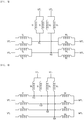
- FIG. 3 is a view for describing a three-phase circuit of the motor according to one embodiment of the present invention
- FIG. 4 is a view illustrating a modified example of FIG. 3
- FIG. 5 is a view for describing an arrangement of a plurality of neutral terminals according to a circuit of FIG. 4 .
- the stator 140 may include a plurality of divided cores 141a and a plurality of coils 142 wound around the divided cores 141a.
- the coil 142 may include one end 142a and the other end 142b which extend from the divided core 141a in a direction of a shaft (a longitudinal direction of the rotating shaft).
- the one end 142a may be a point from which coil winding starts, and the other end 142b may be a point at which the coil winding ends.
- the one end 142a and the other end 142b are not limited thereto.
- the one end 142a may be a position at which coil winding ends
- the other end 142b may be a position from which the coil winding starts.
- each of the plurality of coils 142 may be electrically connected to a neutral terminal 162, and the other end 142b may also be electrically connected to any one of driving terminals 163.
- the busbar 160 may include an insulating body 161, a plurality of neutral terminals 162, and a plurality of driving terminals 163.
- the insulating body 161 electrically insulates the plurality of neutral terminals 162 from the plurality of driving terminals 163.
- the insulating body 161 may include a plurality of insertion grooves 161b in which the plurality of driving terminals 163 may be installed.
- the neutral terminal 162 is integrally injected with the insulating body 161 as example, but is not limited thereto.
- a material of the insulating body 161 is not specifically limited as long as the material has an insulating property.
- the insulating body 161 may be formed by injection-molding a plastic resin.
- the plurality of insertion grooves 161b may be formed to have a predetermined distance to electrically insulate the driving terminals 163.
- a distance between the insertion grooves 161b may be 0.5 mm to 2.0 mm, but is not limited thereto.
- the plurality of insertion grooves 161b may have the same spiral shape.
- the insulating body 161 may have a circular plate shape in which a first hole 161a is formed in a center thereof, but is not limited thereto.
- the neutral terminal 162 may serve to connect neutral points of the plurality of coils 142.
- the neutral terminal 162 may include the plurality of neutral terminals 162 which are electrically insulated.
- the motor 100 may include a plurality of neutral points, and the plurality of neutral points may be electrically insulated.
- the plurality of driving terminals 163 may be connected to a power terminal 164. That is, the driving terminal 163 may be structurally separated from the power terminal 164. In such a structure, an inverter may be directly connected to an upper side of the busbar 160, and the structure of the power terminal 164 may be suitably changed according to a structure of the motor. However, the structure of the power terminal 164 is not limited thereto and may also be a power cable type.
- the power terminal 164 may include a plurality of connection fins 164b electrically connected to the plurality of driving terminals 163 and a fixed part 164a at which the connection fins 164b are disposed.
- the plurality of driving terminals 163 may serve to supply three-phase power to the coil 142.
- a three-phase circuit may be formed by electrically connecting the terminals of the busbar 160 and the coils 142
- the plurality of driving terminals 163 may include a plurality of first driving terminals UT1 and UT2, second driving terminals VT1 and VT2, and third driving terminals WT1 and WT2.
- the first driving terminals UT1 and UT2 may be U-phase terminals
- the second driving terminals VT1 and VT2 may be V-phase terminals
- the third driving terminals WT1 and WT2 may be W-phase terminals.
- the U-phase terminals UT1 and UT2 may include a first U-phase terminal UT1 and a second U-phase terminal UT2, the V-phase terminals VT1 and VT2 may include a first V-phase terminal VT1 and a second V-phase terminal VT2, and the W-phase terminals WT1 and WT2 may include a first W-phase terminal WT1 and a second W-phase terminal WT2.
- a plurality of three-phase circuits may be formed in the motor.
- the number of terminals is not limited.
- the motor may include two independent three-phase circuits.
- a first circuit may be formed by connecting the first U-phase terminal UT1, the first V-phase terminal VT1, and the first W-phase terminal WT1 to a plurality of coils U1, U3, V1, V3, W1, and W3.
- the second circuit may be formed by connecting the second U-phase terminal UT2, the second V-phase terminal VT2, and the second W-phase terminal WT2 to a plurality of coils U2, U4, V2, V4, W2, and W4.
- the first circuit may be an independent circuit connected by a first neutral point N1
- the second circuit may be an independent circuit connected by a second neutral point N2.
- a set of coils constituting the first circuit may be defined as a first coil set U1, U3, V1, V3, W1, and W3, and a set of coils constituting the second circuit is defined as a second coil set U2, U4, V2, V4, W2, and W4.
- a motor may also include four neutral points N1 to N4.
- a first circuit may include a first neutral point N1 and a second neutral point N2, and a second circuit may include a third neutral point N3 and a fourth neutral point N4.
- a three-phase circuit may also have more neutral points as necessary.
- four neutral terminals 162 may be disposed to include four neutral points which are electrically insulated.
- the neutral terminals 162 may have the same shape.
- the neutral terminal may include a body portion 1621 having a curvature, an extension portion 1622 bent in the direction of the shaft, and a connection portion 1623.
- neutral terminal is not limited thereto.
- Two neutral terminals 162 may also be disposed to include two neutral points as illustrated in FIG. 3 , and shapes thereof may also be different.
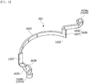
- FIG. 6 is a view for describing a shape of a driving terminal
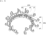
- FIG. 7 is a view for describing an arrangement of a plurality of driving terminals
- FIG. 8 is a plan view of FIG. 7 .
- each of the plurality of driving terminals 163 may include a body portion 1631, a connection portion 1634 connected to the body portion 1631, and a terminal portion 1635 protruding from the body portion 1631 in the direction of the shaft.
- the body portion 1631 extends in a predetermined length to connect a plurality of connection portions 1634.
- the body portion 1631 may have a strip shape having a curvature. A radius of the curvature of the body portion 1631 may change from one end 1632 toward the other end 1633.
- the body portion 1631 may have a spiral shape.
- the spiral shape may be defined as a shape in which a radius of a curvature changes from the one end 1632 toward the other end 1633.
- a radius of the curvature may increase from the one end 1632 toward the other end 1633.
- the radius of the curvature is not limited thereto, and may also decrease from the one end toward the other end.
- the radius of the curvature at the one end 1632 is 20 mm, and a radius of the curvature at the other end 1633 may be 30 mm, but the radii are not limited thereto.
- the plurality of terminals configured to connect phases are disposed in the motor according to the embodiment as described above. Accordingly, the number of terminals may increase to two times that of a conventional motor. Such a spiral shape may be advantageous for arranging the plurality of terminals in a limited space.
- a thickness of the body portion 1631 may range from 0.5 to 2.0 mm, but is not limited thereto.
- connection portion 1634 is a portion electrically connected to the coil.
- the connection portion 1634 may have a hook or Y shape, but is not limited thereto.
- the connection portion 1634 may include a first connection portion 1634a connected to the one end 1632 of the body portion 1631 and a second connection portion 1634b connected to the other end 1633 of the body portion 1631. The number of connection portions may be increased as necessary.
- the terminal portion 1635 may protrude from the body portion 1631 in the direction of the shaft.
- the terminal portion 1635 may be connected to an external power or an inverter to supply power to the connection portion 1634.
- An extension portion 1638 may be formed between the body portion 1631 and the connection portion 1634.
- the extension portion 1638 may include a first bent portion 1637 protruding in the direction of the shaft and a second bent portion 1636 extending from the first bent portion 1637 in a direction perpendicular to the shaft.
- a height of the connection portion 1634 may be determined according to that of the first bent portion 1637.
- the terminal portion 1635 may also be disposed on the extension portion 1638.
- a length of the second bent portion 1636 connected to the first connection portion 1634a may be longer than that of the second bent portion 1636 connected to the second connection portion 1634b.
- Such a structure may expose the connection portion at the outside of the insulating body to allow the connection portion to be electrically connected to the coil in a spiral type arrangement.
- all of the plurality of U-phase terminals UT1 and UT2, the V-phase terminals VT1 and VT2, and the W-phase terminals WT1 and WT2 may have the same shape.
- the terminals do not need to be separately manufactured, there is an effect in that a manufacturing cost is reduced, and there is an advantage in that an assembly is simplified.
- All of the plurality of U-phase terminals UT1 and UT2, V-phase terminals VT1 and VT2, and W-phase terminals WT1 and WT2 may be disposed to be coplanar. That is, the plurality of U-phase terminals UT1 and UT2, V-phase terminals VT1 and VT2, and W-phase terminals WT1 and WT2 may be connected to the coils at the same height.
- the first U-phase terminal UT1, the first V-phase terminal VT1, and the first W-phase terminal WT1 may be a first terminal set 163a constituting the first circuit
- the second U-phase terminal UT2, the second V-phase terminal VT2, and the second W-phase terminal WT2 may be a second terminal set 163b constituting the second circuit.
- a diameter of a first virtual circle CL1 which connects the one ends 1632 of the first U-phase terminal UT1, the second U-phase terminal UT2, the first V-phase terminal VT1, the second V-phase terminal VT2, the first W-phase terminal WT1 and the second W-phase terminal WT2 may be less than that of a second virtual circle CL2 which connects the other ends 1633 thereof. Accordingly, the first U-phase terminal UT1, the second U-phase terminal UT2, the first V-phase terminal VT1, the second V-phase terminal VT2, the first W-phase terminal WT1 and the second W-phase terminal WT2 may be densely disposed in a limited space.
- a diameter of the first hole 161a formed in the insulating body may be less than that of the first virtual circle CL1, and the first hole 161a, the first virtual circle CL1, and the second virtual circle CL2 may have the same center P.
- all angles ⁇ between virtual lines L1 to L6 from the center P to the one ends 1632 of the terminals may be the same.
- FIG. 9 is a block diagram of a power transmission system according to one embodiment of the present invention
- FIG. 10 is a modified example of FIG. 9 .
- a power transmission system includes a motor 100 having a first circuit 100a and a second circuit 100b, a first driving unit 30 electrically connected to the first circuit 100a, a second driving unit 40 electrically connected to the second circuit 100b, and a control unit 10 configured to control the first driving unit 30 and the second driving unit 40.
- the first circuit 100a and the second circuit 100b of the motor 100 having the same configurations as described above may be included in the power transmission system.
- the first circuit 100a includes a first coil set and a first terminal set configured to electrically connect the first coil set
- the second circuit 100b includes a second coil set and a second terminal set configured to electrically connect the second coil set.
- the first terminal set may include a first U-phase terminal UT1, a first V-phase terminal VT1, and a first W-phase terminal WT1
- the second terminal set may include a second U-phase terminal UT2, a second V-phase terminal VT2, and a second W-phase terminal WT2.
- Each of the first driving unit 30 and the second driving unit 40 may be an inverter configured to convert direct current (DC) power supplied from a power source 20 into three-phase power.
- the power source 20 may be a vehicle battery.
- the first driving unit 30 may be connected to U-phase, V-phase, and W-phase of the first circuit 100a to supply three-phase power to the first circuit 100a
- the second driving unit 40 may be connected to U-phase, V-phase, and W-phase of the second circuit 100b to supply three-phase power to the second circuit 100b. That is, the first driving unit 30 and the second driving unit 40 may independently drive the first circuit 100a and the second circuit 100b. Accordingly, even in a case in which any one of the first driving unit 30 and the second driving unit 40 does not operate, the motor 100 may be operated by the remaining driving unit. Accordingly, the power transmission system may be suitable for the field such as a vehicle demanding a high level of safety.
- the control unit 10 may output a control signal to the first driving unit 30 and the second driving unit 40 according to driving conditions detected by a vehicle speed sensor, torque angle sensor, torque sensor, and the like.
- the control unit 10 may be an electronic control unit (ECU).
- control unit 10 may include a first control unit 11 configured to control the first driving unit 30 and a second control unit 12 configured to control the second driving unit 40.
- the motor may be controlled by the remaining control unit.
Description
- The present invention relates to a busbar, a motor, and a power transmission system including the same.
- Generally, an electronic power steering (EPS) system is a system for securing steering safety of a vehicle, and allows easy handling by supplying power using a motor in a direction in which a driver steers the vehicle.
- Such an EPS system may improve a steering performance and a steering feeling by controlling an operation of the motor according to a driving condition unlike a conventional hydraulic power steering (HPS) system.
- Specifically, the EPS system controls an inverter to drive the motor according to driving conditions detected by a vehicle speed sensor, a torque angle sensor, a torque sensor, and the like of an electronic control unit (ECU). Accordingly, since a turning safety is secured and a rapid restoring force is provided, the driver may safely drive.
- Recently, safety requirements have been increased in the field of vehicles. Accordingly, a technology in which a safety of a vehicle is secured even when some parts (ECU or inverter) of the EPS system are in impossible operation states is required.
-
EP 2849315 A2 discloses a bus bar, including an insulator and a plurality of terminals inserted into the insulator and connected to the coil of a stator.US 2008/136274 A1 discloses a stator of a motor includes a plurality of busbar plates, each laminated above a stator core in an axial direction and connected to a plurality of wires having a substantially U-shaped configuration. - The present invention is directed to providing a busbar with which a plurality of three-phase circuits may be formed.
- The present invention is also directed to providing a motor having a plurality of three-phase circuits which are independently controlled.
- The present invention is also directed to providing a power transmission system in which a plurality of inverters control a motor.
- One aspect of the present invention provides a busbar according to
claim 1 including: an insulating body; a plurality of neutral terminals disposed on the insulating body; and a plurality of first driving terminals, second driving terminals, and third driving terminals disposed on the insulating body, wherein the plurality of neutral terminals, first driving terminals, second driving terminals, and third driving terminals are electrically insulated from each other, and the plurality of first driving terminals, second driving terminals, and third driving terminals have the same shape. - The insulating body may include insertion grooves in which the plurality of first driving terminals, second driving terminals, and third driving terminals are disposed.
- The plurality of neutral terminals may have the same shape.
- The plurality of first driving terminals, second driving terminals, and third driving terminals may be coplanar.
- A radius of a curvature at one end of each of the plurality of first driving terminals, second driving terminals, and third driving terminals is different from that of a curvature at the other end thereof.
- The curvature of each of the plurality of first driving terminals, second driving terminals, and third driving terminals changes from the one end of each of the plurality of first driving terminals, second driving terminals, and third driving terminals toward the other end thereof.
- Each of the plurality of first driving terminals, second driving terminals, and third driving terminals includes: a body portion; a connection portion connected to the body portion; and a terminal portion protruding from the body portion in a direction of a shaft.
- The connection portion includes a first connection portion connected to one end of the body portion, and a second connection portion connected to the other end of the body portion.
- The busbar may further include extension portions disposed between the connection portion and the body portion, wherein the extension portions may extend in a direction perpendicular to the direction of the shaft, and a length of the extension portion connected to the first connection portion may be different from that of the extension portion connected to the second connection portion.
- The length of the extension portion connected to the first connection portion may be greater than that of the extension portion connected to the second connection portion.
- A curvature of the body portion may be changed from one end of the body portion toward the other end thereof.
- Another aspect of the present invention provides a busbar including an insulating body and a plurality of first, second, and third driving terminals disposed on the insulating body, wherein a diameter of a first virtual circle connecting one ends of the plurality of first, second, and third driving terminals is less than that of a second virtual circle connecting the other ends thereof.
- The insulating body may include a first hole formed at a center of the insulating body, and a diameter of the first hole may be less than that of the first virtual circle.
- Centers of the first hole, the first virtual circle, and the second virtual circle may be the same.
- Still another aspect of the present invention provides a motor including a stator including a first coil set and a second coil set, and a busbar including a first terminal set electrically connected to the first coil set to constitute a first circuit, a second terminal set electrically connected to the second coil set to constitute a second circuit, and an insulating body configured to fix the first and second terminal sets, wherein each of the first terminal set and the second terminal set includes at least one first driving terminal, at least one second driving terminal, and least one third driving terminal, and the first driving terminal, the second driving terminal, and the third driving terminal have the same shape.
- A curvature of each of the first driving terminal, the second driving terminal, and the third driving terminal is changed from one end of each of the first driving terminal, the second driving terminal, and the third driving terminal toward the other end thereof.
- Yet another aspect of the present invention provides a power transmission system including: a motor including a first circuit and a second circuit; a first driving unit electrically connected to the first circuit; a second driving unit electrically connected to the second circuit; and a control unit configured to control the first driving unit and the second driving unit, wherein the first circuit includes a first coil set and a first terminal set configured to electrically connect the first coil set, and the second circuit includes a second coil set and a second terminal set configured to electrically connect the second coil set.
- According to embodiments, since a plurality of three-phase circuits can be formed in a single motor, reliability can be improved.
- Since shapes of terminals are the same, a manufacturing cost can be reduced.
- Since the terminal is formed in a spiral shape, the plurality of terminals can be densely disposed, and thus a size of the plurality of terminals can be reduced.
- Since a power terminal is separately manufactured, a manufacturing process can be simplified.
- Since the terminals having the same shape are assembled, a structure of an insulator can be simplified, and a productivity of an assembly process can be improved.
- Useful advantages and effects of the present invention are not limited to the above-described contents, and may be more easily understood from specific embodiments of the present invention which will be described.
-
-
FIG. 1 is a cross-sectional view illustrating a motor according to one embodiment of the present invention. -
FIG. 2 is a view for describing a state in which a busbar and a stator according to one embodiment of the present invention are electrically connected. -
FIG. 3 is a view for describing a three-phase circuit of the motor according to one embodiment of the present invention. -
FIG. 4 is a view illustrating a modified example ofFIG. 3 . -
FIG. 5 is a view for describing an arrangement of a plurality of neutral terminals according to a circuit ofFIG. 4 . -
FIG. 6 is a view for describing a shape of a driving terminal. -
FIG. 7 is a view for describing an arrangement of a plurality of driving terminals. -
FIG. 8 is a plan view ofFIG. 7 . -
FIG. 9 is a block diagram of a power transmission system according to one embodiment of the present invention. -
FIG. 10 is a view illustrating a modified example ofFIG. 9 . - While the present invention may be modified in various ways and take on various alternative forms, specific embodiments thereof are shown in the accompanying drawings and described in detail below as examples. However, there is no intent to limit the present invention to the particular forms disclosed. On the contrary, the present invention is to cover all modifications, equivalents, and alternatives falling within the scope of the appended claims.
- It should be understood that, although terms "first," "second," and the like may be used herein to describe various elements, the elements are not limited by the terms. The terms are only used to distinguish one element from another. For example, a first element could be termed a second element, and similarly, a second element could be termed a first element without departing from the scope of the present invention. As used herein, the term "and/or" includes any and all combinations of one or more of the associated listed items.
- Terms used in the present specification are merely used to describe exemplary embodiments, and are not intended to limit the embodiments. An expression used in the singular encompasses the expression of the plural, unless it has a clearly different meaning in the context. In the present specification, it should be understood that the terms such as "including," "having," and "comprising" are intended to indicate the existence of features, numbers, steps, actions, components, parts, or combinations thereof disclosed in the specification, and are not intended to preclude the possibility that one or more other features, numbers, steps, actions, components, parts, or combinations thereof may exist or be added.
- In the description of embodiments, when an element is referred to as being "on or under" another element, the term "on or under" refers to either a direct connection between two elements or an indirect connection between two elements having one or more elements formed therebetween. In addition, when the term "on or under" is used, it may refer to a downward direction as well as an upward direction with respect to an element.
- Hereinafter, embodiments will be illustrated in detail with reference to the accompanying drawings, and components that are the same or correspond to each other regardless of reference numerals will be referred to by the same or similar reference numerals, and redundant descriptions thereof will be omitted.
-
FIG. 1 is a cross-sectional view illustrating a motor according to one embodiment of the present invention. - Referring to
FIG. 1 , amotor 100 according to one embodiment of the present invention includes ahousing 110, astator 140 disposed in thehousing 110, arotor 130, arotating shaft 150, and abusbar 160. - The
housing 110 may accommodate thestator 140 and therotor 130. Thehousing 110 may further include a cooling structure (not shown) to easily dissipate internal heat thereof. The cooling structure may be an air or water cooling structure, but is not limited thereto. - The
stator 140 is inserted into an inner space of thehousing 110. Thestator 140 may include astator core 141 and coils 142 wound around thestator core 141. Thestator core 141 may include a plurality of divided cores. However, thestator core 141 is not limited thereto, and may also be integrally formed. - The
rotor 130 may be disposed to rotate with respect to thestator 140. That is, therotor 130 may rotate inside thestator 140. Arotor magnet 132 may be installed on an outer circumferential surface of therotor 130. - The
rotating shaft 150 may be coupled to a central portion of therotor 130. Accordingly, therotor 130 and therotating shaft 150 may rotate together. Therotating shaft 150 may be supported by afirst bearing 171 disposed at one side thereof and asecond bearing 172 disposed at the other side thereof. - The
busbar 160 may include a plurality of terminals electrically connected to thecoils 142 wound around thestator 140 and configured to connect a U-phase, a V-phase, and a W-phase. Apower terminal 164 of thebusbar 160 may be exposed at the outside to be electrically connected to an external power or inverter. -
FIG. 2 is a view for describing a state in which a busbar and a stator according to one embodiment of the present invention are electrically connected,FIG. 3 is a view for describing a three-phase circuit of the motor according to one embodiment of the present invention,FIG. 4 is a view illustrating a modified example ofFIG. 3 , andFIG. 5 is a view for describing an arrangement of a plurality of neutral terminals according to a circuit ofFIG. 4 . - Referring to
FIG. 2 , thestator 140 may include a plurality of dividedcores 141a and a plurality ofcoils 142 wound around the dividedcores 141a. Thecoil 142 may include oneend 142a and theother end 142b which extend from the dividedcore 141a in a direction of a shaft (a longitudinal direction of the rotating shaft). The oneend 142a may be a point from which coil winding starts, and theother end 142b may be a point at which the coil winding ends. However, the oneend 142a and theother end 142b are not limited thereto. For example, the oneend 142a may be a position at which coil winding ends, and theother end 142b may be a position from which the coil winding starts. - The one
end 142a of each of the plurality ofcoils 142 may be electrically connected to aneutral terminal 162, and theother end 142b may also be electrically connected to any one of drivingterminals 163. - The
busbar 160 may include an insulatingbody 161, a plurality ofneutral terminals 162, and a plurality of drivingterminals 163. - The insulating
body 161 electrically insulates the plurality ofneutral terminals 162 from the plurality of drivingterminals 163. The insulatingbody 161 may include a plurality ofinsertion grooves 161b in which the plurality of drivingterminals 163 may be installed. Theneutral terminal 162 is integrally injected with the insulatingbody 161 as example, but is not limited thereto. A material of the insulatingbody 161 is not specifically limited as long as the material has an insulating property. For example, the insulatingbody 161 may be formed by injection-molding a plastic resin. - The plurality of
insertion grooves 161b may be formed to have a predetermined distance to electrically insulate the drivingterminals 163. A distance between theinsertion grooves 161b may be 0.5 mm to 2.0 mm, but is not limited thereto. The plurality ofinsertion grooves 161b may have the same spiral shape. The insulatingbody 161 may have a circular plate shape in which afirst hole 161a is formed in a center thereof, but is not limited thereto. - The
neutral terminal 162 may serve to connect neutral points of the plurality ofcoils 142. Here, theneutral terminal 162 may include the plurality ofneutral terminals 162 which are electrically insulated. Accordingly, themotor 100 may include a plurality of neutral points, and the plurality of neutral points may be electrically insulated. - The plurality of driving
terminals 163 may be connected to apower terminal 164. That is, the drivingterminal 163 may be structurally separated from thepower terminal 164. In such a structure, an inverter may be directly connected to an upper side of thebusbar 160, and the structure of thepower terminal 164 may be suitably changed according to a structure of the motor. However, the structure of thepower terminal 164 is not limited thereto and may also be a power cable type. Thepower terminal 164 may include a plurality ofconnection fins 164b electrically connected to the plurality of drivingterminals 163 and afixed part 164a at which theconnection fins 164b are disposed. - The plurality of driving
terminals 163 may serve to supply three-phase power to thecoil 142. A three-phase circuit may be formed by electrically connecting the terminals of thebusbar 160 and thecoils 142 - The plurality of driving
terminals 163 may include a plurality of first driving terminals UT1 and UT2, second driving terminals VT1 and VT2, and third driving terminals WT1 and WT2. The first driving terminals UT1 and UT2 may be U-phase terminals, the second driving terminals VT1 and VT2 may be V-phase terminals, and the third driving terminals WT1 and WT2 may be W-phase terminals. - The U-phase terminals UT1 and UT2 may include a first U-phase terminal UT1 and a second U-phase terminal UT2, the V-phase terminals VT1 and VT2 may include a first V-phase terminal VT1 and a second V-phase terminal VT2, and the W-phase terminals WT1 and WT2 may include a first W-phase terminal WT1 and a second W-phase terminal WT2. In such a configuration, a plurality of three-phase circuits may be formed in the motor. However, the number of terminals is not limited.
- Referring to
FIGS. 3 and 4 , the motor may include two independent three-phase circuits. A first circuit may be formed by connecting the first U-phase terminal UT1, the first V-phase terminal VT1, and the first W-phase terminal WT1 to a plurality of coils U1, U3, V1, V3, W1, and W3. - The second circuit may be formed by connecting the second U-phase terminal UT2, the second V-phase terminal VT2, and the second W-phase terminal WT2 to a plurality of coils U2, U4, V2, V4, W2, and W4. The first circuit may be an independent circuit connected by a first neutral point N1, and the second circuit may be an independent circuit connected by a second neutral point N2.
- Here, a set of coils constituting the first circuit may be defined as a first coil set U1, U3, V1, V3, W1, and W3, and a set of coils constituting the second circuit is defined as a second coil set U2, U4, V2, V4, W2, and W4.
- Referring to
FIG. 4 , a motor may also include four neutral points N1 to N4. A first circuit may include a first neutral point N1 and a second neutral point N2, and a second circuit may include a third neutral point N3 and a fourth neutral point N4. A three-phase circuit may also have more neutral points as necessary. - Referring to
FIG. 5 , fourneutral terminals 162 may be disposed to include four neutral points which are electrically insulated. Here, theneutral terminals 162 may have the same shape. Specifically, the neutral terminal may include abody portion 1621 having a curvature, anextension portion 1622 bent in the direction of the shaft, and aconnection portion 1623. - However, the neutral terminal is not limited thereto. Two
neutral terminals 162 may also be disposed to include two neutral points as illustrated inFIG. 3 , and shapes thereof may also be different. -
FIG. 6 is a view for describing a shape of a driving terminal,FIG. 7 is a view for describing an arrangement of a plurality of driving terminals, andFIG. 8 is a plan view ofFIG. 7 . - Referring to
FIG. 6 , each of the plurality of drivingterminals 163 may include abody portion 1631, aconnection portion 1634 connected to thebody portion 1631, and aterminal portion 1635 protruding from thebody portion 1631 in the direction of the shaft. - The
body portion 1631 extends in a predetermined length to connect a plurality ofconnection portions 1634. Thebody portion 1631 may have a strip shape having a curvature. A radius of the curvature of thebody portion 1631 may change from oneend 1632 toward theother end 1633. - The
body portion 1631 may have a spiral shape. Here, the spiral shape may be defined as a shape in which a radius of a curvature changes from the oneend 1632 toward theother end 1633. A radius of the curvature may increase from the oneend 1632 toward theother end 1633. However, the radius of the curvature is not limited thereto, and may also decrease from the one end toward the other end. The radius of the curvature at the oneend 1632 is 20 mm, and a radius of the curvature at theother end 1633 may be 30 mm, but the radii are not limited thereto. - As described above, the plurality of terminals configured to connect phases are disposed in the motor according to the embodiment as described above. Accordingly, the number of terminals may increase to two times that of a conventional motor. Such a spiral shape may be advantageous for arranging the plurality of terminals in a limited space. A thickness of the
body portion 1631 may range from 0.5 to 2.0 mm, but is not limited thereto. - The
connection portion 1634 is a portion electrically connected to the coil. Theconnection portion 1634 may have a hook or Y shape, but is not limited thereto. Theconnection portion 1634 may include afirst connection portion 1634a connected to the oneend 1632 of thebody portion 1631 and asecond connection portion 1634b connected to theother end 1633 of thebody portion 1631. The number of connection portions may be increased as necessary. - The
terminal portion 1635 may protrude from thebody portion 1631 in the direction of the shaft. Theterminal portion 1635 may be connected to an external power or an inverter to supply power to theconnection portion 1634. - An
extension portion 1638 may be formed between thebody portion 1631 and theconnection portion 1634. - The
extension portion 1638 may include a firstbent portion 1637 protruding in the direction of the shaft and a secondbent portion 1636 extending from the firstbent portion 1637 in a direction perpendicular to the shaft. A height of theconnection portion 1634 may be determined according to that of the firstbent portion 1637. Theterminal portion 1635 may also be disposed on theextension portion 1638. - A length of the second
bent portion 1636 connected to thefirst connection portion 1634a may be longer than that of the secondbent portion 1636 connected to thesecond connection portion 1634b. Such a structure may expose the connection portion at the outside of the insulating body to allow the connection portion to be electrically connected to the coil in a spiral type arrangement. - Referring to
FIG. 7 , all of the plurality of U-phase terminals UT1 and UT2, the V-phase terminals VT1 and VT2, and the W-phase terminals WT1 and WT2 may have the same shape. In this case, since the terminals do not need to be separately manufactured, there is an effect in that a manufacturing cost is reduced, and there is an advantage in that an assembly is simplified. - All of the plurality of U-phase terminals UT1 and UT2, V-phase terminals VT1 and VT2, and W-phase terminals WT1 and WT2 may be disposed to be coplanar. That is, the plurality of U-phase terminals UT1 and UT2, V-phase terminals VT1 and VT2, and W-phase terminals WT1 and WT2 may be connected to the coils at the same height.
- The first U-phase terminal UT1, the first V-phase terminal VT1, and the first W-phase terminal WT1 may be a
first terminal set 163a constituting the first circuit, and the second U-phase terminal UT2, the second V-phase terminal VT2, and the second W-phase terminal WT2 may be a second terminal set 163b constituting the second circuit. - Referring to
FIG. 8 , a diameter of a first virtual circle CL1 which connects the one ends 1632 of the first U-phase terminal UT1, the second U-phase terminal UT2, the first V-phase terminal VT1, the second V-phase terminal VT2, the first W-phase terminal WT1 and the second W-phase terminal WT2 may be less than that of a second virtual circle CL2 which connects the other ends 1633 thereof. Accordingly, the first U-phase terminal UT1, the second U-phase terminal UT2, the first V-phase terminal VT1, the second V-phase terminal VT2, the first W-phase terminal WT1 and the second W-phase terminal WT2 may be densely disposed in a limited space. - Here, a diameter of the
first hole 161a formed in the insulating body may be less than that of the first virtual circle CL1, and thefirst hole 161a, the first virtual circle CL1, and the second virtual circle CL2 may have the same center P. In addition, all angles θ between virtual lines L1 to L6 from the center P to the one ends 1632 of the terminals may be the same. -
FIG. 9 is a block diagram of a power transmission system according to one embodiment of the present invention, andFIG. 10 is a modified example ofFIG. 9 . - Referring to
FIG. 9 , a power transmission system according to one embodiment of the present invention includes amotor 100 having afirst circuit 100a and asecond circuit 100b, afirst driving unit 30 electrically connected to thefirst circuit 100a, asecond driving unit 40 electrically connected to thesecond circuit 100b, and acontrol unit 10 configured to control thefirst driving unit 30 and thesecond driving unit 40. - The
first circuit 100a and thesecond circuit 100b of themotor 100 having the same configurations as described above may be included in the power transmission system. Thefirst circuit 100a includes a first coil set and a first terminal set configured to electrically connect the first coil set, and thesecond circuit 100b includes a second coil set and a second terminal set configured to electrically connect the second coil set. - The first terminal set may include a first U-phase terminal UT1, a first V-phase terminal VT1, and a first W-phase terminal WT1, and the second terminal set may include a second U-phase terminal UT2, a second V-phase terminal VT2, and a second W-phase terminal WT2.
- Each of the
first driving unit 30 and thesecond driving unit 40 may be an inverter configured to convert direct current (DC) power supplied from apower source 20 into three-phase power. Thepower source 20 may be a vehicle battery. - The
first driving unit 30 may be connected to U-phase, V-phase, and W-phase of thefirst circuit 100a to supply three-phase power to thefirst circuit 100a, and thesecond driving unit 40 may be connected to U-phase, V-phase, and W-phase of thesecond circuit 100b to supply three-phase power to thesecond circuit 100b. That is, thefirst driving unit 30 and thesecond driving unit 40 may independently drive thefirst circuit 100a and thesecond circuit 100b. Accordingly, even in a case in which any one of thefirst driving unit 30 and thesecond driving unit 40 does not operate, themotor 100 may be operated by the remaining driving unit. Accordingly, the power transmission system may be suitable for the field such as a vehicle demanding a high level of safety. - The
control unit 10 may output a control signal to thefirst driving unit 30 and thesecond driving unit 40 according to driving conditions detected by a vehicle speed sensor, torque angle sensor, torque sensor, and the like. Thecontrol unit 10 may be an electronic control unit (ECU). - Referring to
FIG. 10 , thecontrol unit 10 may include afirst control unit 11 configured to control thefirst driving unit 30 and asecond control unit 12 configured to control thesecond driving unit 40. In this case, even in a case in which any one of thefirst control unit 11 and thesecond control unit 12 does not operate, the motor may be controlled by the remaining control unit.
Claims (12)
- A busbar comprising:an insulating body (161);a plurality of neutral terminals (162) disposed on the insulating body (161); anda plurality of first driving terminals (UT1, UT2), a plurality of second driving terminals (VT1, VT2), and a plurality of third driving terminals (WT1, WT2) disposed on the insulating body (161),wherein the plurality of first driving terminals (UT1, UT2), second driving terminals (VT1, VT2), and third driving terminals (WT1, WT2) have the same shape,wherein a diameter of a first virtual circle (CL1) connected to first ends of the plurality of the first driving terminals (UT1, UT2), the second driving terminals (VT1, VT2), and the third driving terminals (WT1, WT2) is smaller than a diameter of a second virtual circle (CL2) connected to second ends of the plurality of the first driving terminals (UT1, UT2), the second driving terminals (VT1, VT2), and the third driving terminals (WT1, WT2),wherein a centers of the first virtual circle (CL1) and the second virtual circle (CL2) are identical,wherein one of the second driving terminals (VT1, VT2) and one of the third driving terminals (WT1, WT2) are disposed radially and circumferentially between the first driving terminals (UT1 UT2),wherein the plurality of neutral terminals (162), first driving terminals (UT1, UT2), second driving terminals (VT1, VT2), and third driving terminals (WT1, WT2) are electrically insulated from each other, andwherein each of the plurality of the first driving terminals (UT1, UT2), the second driving terminals (VT1, VT2), and the third driving terminals (WT1, WT2) comprises:a body portion (1631) comprising the first end and the second end;a first connection portion (1634a) connected to the first end of the body portion (1631); anda second connection portion (1634b) connected to the second end of the body portion (1631),wherein the first connection portion (1634a) and the second connection portion (1634b) protrude toward an outside of the second virtual circle (CL2), andwherein a radius of a curvature at one end of each of the plurality of first driving terminals (UT1, UT2), second driving terminals (VT1, VT2), and third driving terminals (WT1, WT2) is different from that of a curvature at the other end thereof, andwherein the curvature of each of the plurality of first driving terminals (UT1, UT2), second driving terminals (VT1, VT2), and third driving terminals (WT1, WT2) is changed from the one end of each of the plurality of first driving terminals (UT1, UT2), second driving terminals (VT1, VT2), and third driving terminals (WT1, WT2) toward the other end thereof.
- The busbar of claim 1, wherein a length of the extension portions connected to the first connection portion (1634a) is longer than a length of the extension portions connected to the second connection portion (1634b).
- The busbar of any one of claims 1 to 2, wherein:the insulating body (161) includes a first hole formed at a center of the insulating body (161),wherein a diameter of the first hole is less than that of the first virtual circle (CL1), andwherein centers of the first hole, the first virtual circle (CL1), and the second virtual circle (CL2) are identical.
- The busbar of any one of claims 1 to 3, wherein the insulating body (161) includes insertion grooves in which the plurality of first driving terminals (UT1, UT2), second driving terminals (VT1, VT2), and third driving terminals (WT1, WT2) are disposed.
- The busbar of any one of claims 1 to 4, wherein the plurality of first driving terminals (UT1, UT2), second driving terminals (VT1, VT2), and third driving terminals (WT1, WT2) are coplanar.
- The busbar of any one of claims 1 to 5, wherein the plurality of neutral terminals (162) has the same shape.
- The busbar of claim 6, wherein the plurality of neutral terminals (162) comprises:a body portion (1621) having a curvature;a connection portion (1623) connected to the body portion (1621); andan extension portion (1622) connected between the body portion (1621) and the connection portion (1623),wherein the connection portion (1623) protrude toward an outside of the second virtual circle (CL2).
- The busbar of any one of claims 1 to 7, wherein the plurality of first driving terminals (UT1, UT2), the plurality of second driving terminals (VT1, VT2), and the plurality of third driving terminals (WT1, WT2) are disposed on the plurality of neutral terminals (162).
- The busbar of claim 1, wherein each of the plurality of the first driving terminals (UT1, UT2), the second driving terminals (VT1, VT2), and the third driving terminals (WT1, WT2) comprises a terminal portion (1635) protruding from the body portion (1631), and
wherein the terminal portion (1635) is closer the second connection portion (1634b) than the first connection portion (1634a). - The busbar of any one of claims 1 to 9, further comprising a power terminal (164) including:a plurality of connection fins (164b) electrically connected to the plurality of the first driving terminals (UT1, UT2), the second driving terminals (VT1, VT2), and the third driving terminals (WT1, WT2) anda fixed part (164a) at which the connection fins (164b) are disposed.
- A motor comprising:a stator (140) including a first coil set and a second coil set; anda busbar (160) according to any one on claims 1 to 10.
- A power transmission system comprising:a motor (100) according to claim 11 including a first circuit and a second circuit;a first driving unit (30) electrically connected to the first circuit;a second driving unit (40) electrically connected to the second circuit; anda control unit (10) configured to control the first driving unit (30) and the second driving unit (40),wherein the first circuit includes a first coil set and a first terminal set (163a) configured to electrically connect the first coil set, and the second circuit includes a second coil set and a second terminal set (163b) configured to electrically connect the second coil set.
Applications Claiming Priority (3)
| Application Number | Priority Date | Filing Date | Title |
|---|---|---|---|
| KR1020150155177A KR102510020B1 (en) | 2015-11-05 | 2015-11-05 | Busbar, motor and power transmission system |
| EP16862471.6A EP3373422B1 (en) | 2015-11-05 | 2016-11-04 | Busbar, motor, and power transmission system using same |
| PCT/KR2016/012644 WO2017078455A1 (en) | 2015-11-05 | 2016-11-04 | Busbar, motor, and power transmission system using same |
Related Parent Applications (2)
| Application Number | Title | Priority Date | Filing Date |
|---|---|---|---|
| EP16862471.6A Division EP3373422B1 (en) | 2015-11-05 | 2016-11-04 | Busbar, motor, and power transmission system using same |
| EP16862471.6A Division-Into EP3373422B1 (en) | 2015-11-05 | 2016-11-04 | Busbar, motor, and power transmission system using same |
Publications (2)
| Publication Number | Publication Date |
|---|---|
| EP3614539A1 EP3614539A1 (en) | 2020-02-26 |
| EP3614539B1 true EP3614539B1 (en) | 2021-03-17 |
Family
ID=58662285
Family Applications (2)
| Application Number | Title | Priority Date | Filing Date |
|---|---|---|---|
| EP16862471.6A Active EP3373422B1 (en) | 2015-11-05 | 2016-11-04 | Busbar, motor, and power transmission system using same |
| EP19199593.5A Active EP3614539B1 (en) | 2015-11-05 | 2016-11-04 | Busbar, motor, and power transmission system using same |
Family Applications Before (1)
| Application Number | Title | Priority Date | Filing Date |
|---|---|---|---|
| EP16862471.6A Active EP3373422B1 (en) | 2015-11-05 | 2016-11-04 | Busbar, motor, and power transmission system using same |
Country Status (6)
| Country | Link |
|---|---|
| US (3) | US10547228B2 (en) |
| EP (2) | EP3373422B1 (en) |
| JP (2) | JP7272793B2 (en) |
| KR (1) | KR102510020B1 (en) |
| CN (2) | CN108352753B (en) |
| WO (1) | WO2017078455A1 (en) |
Families Citing this family (31)
| Publication number | Priority date | Publication date | Assignee | Title |
|---|---|---|---|---|
| KR102510020B1 (en) * | 2015-11-05 | 2023-03-14 | 엘지이노텍 주식회사 | Busbar, motor and power transmission system |
| CN108702059B (en) | 2016-03-02 | 2021-08-03 | Lg伊诺特有限公司 | Bus bar assembly and motor including the same |
| WO2018025990A1 (en) * | 2016-08-05 | 2018-02-08 | 日本電産株式会社 | Motor |
| DE102017106399B4 (en) * | 2017-03-24 | 2023-10-05 | Nidec Corporation | Electric motor |
| WO2018180817A1 (en) * | 2017-03-31 | 2018-10-04 | 日本電産株式会社 | Busbar unit and motor |
| US10756459B2 (en) * | 2017-07-31 | 2020-08-25 | Pentair Flow Technologies, Llc | Ring-style terminal block and submersible pump with ring-style terminal block |
| KR102489299B1 (en) * | 2017-09-06 | 2023-01-17 | 엘지이노텍 주식회사 | Motor |
| JP6930340B2 (en) * | 2017-09-28 | 2021-09-01 | 日本電産株式会社 | motor |
| JP6940358B2 (en) * | 2017-09-29 | 2021-09-29 | 日本電産エレシス株式会社 | Circuit board, motor drive and electric power steering |
| CN111295819B (en) * | 2017-10-31 | 2022-08-26 | Lg伊诺特有限公司 | Bus bar and motor including the same |
| KR102547568B1 (en) * | 2017-12-04 | 2023-06-26 | 엘지이노텍 주식회사 | Motor |
| KR102527781B1 (en) * | 2018-01-05 | 2023-05-02 | 엘지이노텍 주식회사 | Motor |
| KR20190095748A (en) | 2018-02-07 | 2019-08-16 | 엘지이노텍 주식회사 | Motor |
| EP3824528A1 (en) * | 2018-07-19 | 2021-05-26 | Sew-Eurodrive GmbH & Co. KG | Electric motor comprising a wiring unit and method for producing an electric motor with comprising a wiring unit |
| JP7366139B2 (en) * | 2018-09-11 | 2023-10-20 | エルジー イノテック カンパニー リミテッド | motor |
| IT201800020473A1 (en) * | 2018-12-20 | 2020-06-20 | Eldor Corp Spa | CONNECTOR FOR ELECTRIC MOTORS |
| KR20200080715A (en) * | 2018-12-27 | 2020-07-07 | 엘지이노텍 주식회사 | Motor |
| EP4250541A3 (en) | 2019-04-24 | 2024-04-10 | Black & Decker Inc. | Outer rotor brushless motor having an axial fan |
| DE112020002658T8 (en) * | 2019-06-06 | 2022-08-04 | Nidec Corporation | BUSBAR ASSEMBLY, STATOR AND METHOD OF MAKING A BUSBAR ASSEMBLY |
| WO2020261866A1 (en) * | 2019-06-28 | 2020-12-30 | 日本電産株式会社 | Busbar and motor |
| KR102171455B1 (en) * | 2019-07-15 | 2020-10-29 | 엘지전자 주식회사 | Motor |
| WO2021025179A1 (en) * | 2019-08-02 | 2021-02-11 | 엘지전자 주식회사 | Stator assembly and motor comprising same |
| DE102019213538A1 (en) * | 2019-09-05 | 2021-03-11 | Vitesco Technologies GmbH | Electric motor |
| US20220376579A1 (en) * | 2019-10-10 | 2022-11-24 | Lg Innotek Co., Ltd. | Motor |
| CN114830501A (en) * | 2019-12-17 | 2022-07-29 | Lg伊诺特有限公司 | Motor |
| DE202020005485U1 (en) * | 2020-01-24 | 2021-06-08 | Brose Fahrzeugteile SE & Co. Kommanditgesellschaft, Würzburg | Contact device of a stator |
| KR102555273B1 (en) | 2020-06-24 | 2023-07-13 | 에이치엘만도 주식회사 | Steering control apparatus |
| WO2022005197A1 (en) * | 2020-07-03 | 2022-01-06 | 엘지이노텍 주식회사 | Busbar and motor comprising same |
| DE102020126842A1 (en) | 2020-10-13 | 2022-04-14 | Minebea Mitsumi Inc. | CONTACTING DEVICE FOR AN ELECTRIC MOTOR |
| US11658538B2 (en) * | 2020-12-07 | 2023-05-23 | Lg Electronics Inc. | Motor operated compressor |
| WO2024016718A1 (en) * | 2022-07-22 | 2024-01-25 | 安徽威灵汽车部件有限公司 | Busbar assembly, motor structure, electric power steering system, and vehicle |
Family Cites Families (20)
| Publication number | Priority date | Publication date | Assignee | Title |
|---|---|---|---|---|
| JP4789676B2 (en) * | 2006-03-29 | 2011-10-12 | トヨタ自動車株式会社 | Terminal module for rotating electric machine and rotating electric machine |
| JP2008022626A (en) * | 2006-07-12 | 2008-01-31 | Mitsubishi Electric Corp | Rotary machine |
| US7723879B2 (en) * | 2006-12-12 | 2010-05-25 | Nidec Corporation | Motor having multiple busbar plates and wire for the same |
| JP4902738B2 (en) * | 2007-05-25 | 2012-03-21 | 三菱電機株式会社 | Brushless motor |
| JP4972170B2 (en) | 2007-11-09 | 2012-07-11 | 三菱電機株式会社 | Stator for rotating electric machine and method for manufacturing the same |
| JP5335265B2 (en) * | 2008-03-28 | 2013-11-06 | 三洋電機株式会社 | Electric motor |
| JP5463663B2 (en) * | 2008-12-15 | 2014-04-09 | トヨタ自動車株式会社 | Stator structure and stator manufacturing method |
| JP4519191B1 (en) | 2009-02-18 | 2010-08-04 | 住友電気工業株式会社 | Power distribution member for stator |
| JP2010239772A (en) * | 2009-03-31 | 2010-10-21 | Nidec Sankyo Corp | Motor |
| KR200456092Y1 (en) * | 2010-03-02 | 2011-10-11 | 계양전기 주식회사 | Busbar device for brushless motor |
| KR20130061283A (en) * | 2011-12-01 | 2013-06-11 | 엘지이노텍 주식회사 | Stator of eps motor |
| JP5930801B2 (en) * | 2012-03-30 | 2016-06-08 | 日立オートモティブシステムズ株式会社 | In-vehicle motor and electric power steering apparatus using the same |
| JP5790603B2 (en) * | 2012-07-23 | 2015-10-07 | 日立金属株式会社 | Power collection and distribution ring and electric motor |
| KR20140016035A (en) * | 2012-07-30 | 2014-02-07 | 엘지이노텍 주식회사 | Motor |
| JP5989496B2 (en) | 2012-10-10 | 2016-09-07 | 株式会社協豊製作所 | Bus ring for stator of rotating electrical machine |
| CN105103411B (en) * | 2013-04-09 | 2018-07-06 | 三菱电机株式会社 | Permanent magnet-type motor and electric power-assisted steering apparatus |
| KR102051599B1 (en) * | 2013-09-16 | 2020-01-08 | 엘지이노텍 주식회사 | Busbar, insulator and motor including the same |
| US9941762B2 (en) * | 2014-07-18 | 2018-04-10 | Denso Corporation | Stator of rotating electric machine |
| WO2017073092A1 (en) | 2015-10-28 | 2017-05-04 | 三菱電機株式会社 | Rotary electric machine |
| KR102510020B1 (en) * | 2015-11-05 | 2023-03-14 | 엘지이노텍 주식회사 | Busbar, motor and power transmission system |
-
2015
- 2015-11-05 KR KR1020150155177A patent/KR102510020B1/en active IP Right Grant
-
2016
- 2016-11-04 US US15/774,185 patent/US10547228B2/en active Active
- 2016-11-04 EP EP16862471.6A patent/EP3373422B1/en active Active
- 2016-11-04 EP EP19199593.5A patent/EP3614539B1/en active Active
- 2016-11-04 WO PCT/KR2016/012644 patent/WO2017078455A1/en active Application Filing
- 2016-11-04 JP JP2018522910A patent/JP7272793B2/en active Active
- 2016-11-04 CN CN201680064672.6A patent/CN108352753B/en active Active
- 2016-11-04 CN CN202010425431.8A patent/CN111585372B/en active Active
-
2019
- 2019-12-18 US US16/719,362 patent/US10892663B2/en active Active
-
2020
- 2020-12-08 US US17/115,390 patent/US11594934B2/en active Active
-
2021
- 2021-10-28 JP JP2021176341A patent/JP2022009652A/en active Pending
Non-Patent Citations (1)
| Title |
|---|
| None * |
Also Published As
| Publication number | Publication date |
|---|---|
| US20200127524A1 (en) | 2020-04-23 |
| CN111585372A (en) | 2020-08-25 |
| JP7272793B2 (en) | 2023-05-12 |
| KR20170052980A (en) | 2017-05-15 |
| US10547228B2 (en) | 2020-01-28 |
| WO2017078455A1 (en) | 2017-05-11 |
| US11594934B2 (en) | 2023-02-28 |
| US10892663B2 (en) | 2021-01-12 |
| CN108352753A (en) | 2018-07-31 |
| EP3614539A1 (en) | 2020-02-26 |
| US20210091624A1 (en) | 2021-03-25 |
| EP3373422A1 (en) | 2018-09-12 |
| JP2022009652A (en) | 2022-01-14 |
| US20180316238A1 (en) | 2018-11-01 |
| CN111585372B (en) | 2022-10-25 |
| JP2018537063A (en) | 2018-12-13 |
| EP3373422A4 (en) | 2018-09-12 |
| KR102510020B1 (en) | 2023-03-14 |
| CN108352753B (en) | 2020-06-12 |
| EP3373422B1 (en) | 2020-01-01 |
Similar Documents
| Publication | Publication Date | Title |
|---|---|---|
| EP3614539B1 (en) | Busbar, motor, and power transmission system using same | |
| EP3098947B1 (en) | Stator and motor using the same | |
| JP5624330B2 (en) | motor | |
| US7514829B2 (en) | Busbar unit for an electric motor | |
| EP3095176B1 (en) | Rotary electric machine stator | |
| JP5578072B2 (en) | Busbar terminal, busbar unit, and motor | |
| EP3163720B1 (en) | Motor, and electric power steering device and vehicle in which said motor is installed | |
| JP2009056867A (en) | Brushless motor and electric power steering device | |
| CN108370188B (en) | Insulator and motor including the same | |
| JP2006340580A (en) | Rotary electric machine | |
| KR20200017931A (en) | Insulator and motor having the same | |
| CN113273059B (en) | Motor with a motor housing having a motor housing with a motor housing | |
| KR20130057149A (en) | Busbar assembly of motor | |
| KR101779608B1 (en) | Mold structure for bus-bar of eps motor and bus-bar of eps motor using the same | |
| JP2008302797A (en) | Electric power steering device | |
| CN114287095B (en) | Motor | |
| JP2012244839A (en) | Stator for rotating electric machine | |
| US20230307983A1 (en) | Motor | |
| WO2024016718A1 (en) | Busbar assembly, motor structure, electric power steering system, and vehicle | |
| JP2008290675A (en) | Electric power steering device | |
| CN114830501A (en) | Motor | |
| JP2007336676A (en) | Electric rotating machine and vehicle | |
| KR20210004191A (en) | Motor | |
| CN110912295A (en) | Stator monomer and motor stator unit |
Legal Events
| Date | Code | Title | Description |
|---|---|---|---|
| PUAI | Public reference made under article 153(3) epc to a published international application that has entered the european phase |
Free format text: ORIGINAL CODE: 0009012 |
|
| STAA | Information on the status of an ep patent application or granted ep patent |
Free format text: STATUS: THE APPLICATION HAS BEEN PUBLISHED |
|
| AC | Divisional application: reference to earlier application |
Ref document number: 3373422 Country of ref document: EP Kind code of ref document: P |
|
| AK | Designated contracting states |
Kind code of ref document: A1 Designated state(s): AL AT BE BG CH CY CZ DE DK EE ES FI FR GB GR HR HU IE IS IT LI LT LU LV MC MK MT NL NO PL PT RO RS SE SI SK SM TR |
|
| STAA | Information on the status of an ep patent application or granted ep patent |
Free format text: STATUS: REQUEST FOR EXAMINATION WAS MADE |
|
| 17P | Request for examination filed |
Effective date: 20200826 |
|
| RBV | Designated contracting states (corrected) |
Designated state(s): AL AT BE BG CH CY CZ DE DK EE ES FI FR GB GR HR HU IE IS IT LI LT LU LV MC MK MT NL NO PL PT RO RS SE SI SK SM TR |
|
| GRAP | Despatch of communication of intention to grant a patent |
Free format text: ORIGINAL CODE: EPIDOSNIGR1 |
|
| STAA | Information on the status of an ep patent application or granted ep patent |
Free format text: STATUS: GRANT OF PATENT IS INTENDED |
|
| INTG | Intention to grant announced |
Effective date: 20201028 |
|
| GRAS | Grant fee paid |
Free format text: ORIGINAL CODE: EPIDOSNIGR3 |
|
| GRAA | (expected) grant |
Free format text: ORIGINAL CODE: 0009210 |
|
| STAA | Information on the status of an ep patent application or granted ep patent |
Free format text: STATUS: THE PATENT HAS BEEN GRANTED |
|
| AC | Divisional application: reference to earlier application |
Ref document number: 3373422 Country of ref document: EP Kind code of ref document: P |
|
| AK | Designated contracting states |
Kind code of ref document: B1 Designated state(s): AL AT BE BG CH CY CZ DE DK EE ES FI FR GB GR HR HU IE IS IT LI LT LU LV MC MK MT NL NO PL PT RO RS SE SI SK SM TR |
|
| REG | Reference to a national code |
Ref country code: GB Ref legal event code: FG4D |
|
| REG | Reference to a national code |
Ref country code: CH Ref legal event code: EP |
|
| REG | Reference to a national code |
Ref country code: DE Ref legal event code: R096 Ref document number: 602016054683 Country of ref document: DE |
|
| REG | Reference to a national code |
Ref country code: IE Ref legal event code: FG4D |
|
| REG | Reference to a national code |
Ref country code: AT Ref legal event code: REF Ref document number: 1373160 Country of ref document: AT Kind code of ref document: T Effective date: 20210415 |
|
| REG | Reference to a national code |
Ref country code: NL Ref legal event code: FP |
|
| REG | Reference to a national code |
Ref country code: LT Ref legal event code: MG9D |
|
| PG25 | Lapsed in a contracting state [announced via postgrant information from national office to epo] |
Ref country code: NO Free format text: LAPSE BECAUSE OF FAILURE TO SUBMIT A TRANSLATION OF THE DESCRIPTION OR TO PAY THE FEE WITHIN THE PRESCRIBED TIME-LIMIT Effective date: 20210617 Ref country code: FI Free format text: LAPSE BECAUSE OF FAILURE TO SUBMIT A TRANSLATION OF THE DESCRIPTION OR TO PAY THE FEE WITHIN THE PRESCRIBED TIME-LIMIT Effective date: 20210317 Ref country code: GR Free format text: LAPSE BECAUSE OF FAILURE TO SUBMIT A TRANSLATION OF THE DESCRIPTION OR TO PAY THE FEE WITHIN THE PRESCRIBED TIME-LIMIT Effective date: 20210618 Ref country code: BG Free format text: LAPSE BECAUSE OF FAILURE TO SUBMIT A TRANSLATION OF THE DESCRIPTION OR TO PAY THE FEE WITHIN THE PRESCRIBED TIME-LIMIT Effective date: 20210617 Ref country code: HR Free format text: LAPSE BECAUSE OF FAILURE TO SUBMIT A TRANSLATION OF THE DESCRIPTION OR TO PAY THE FEE WITHIN THE PRESCRIBED TIME-LIMIT Effective date: 20210317 |
|
| REG | Reference to a national code |
Ref country code: AT Ref legal event code: MK05 Ref document number: 1373160 Country of ref document: AT Kind code of ref document: T Effective date: 20210317 |
|
| PG25 | Lapsed in a contracting state [announced via postgrant information from national office to epo] |
Ref country code: RS Free format text: LAPSE BECAUSE OF FAILURE TO SUBMIT A TRANSLATION OF THE DESCRIPTION OR TO PAY THE FEE WITHIN THE PRESCRIBED TIME-LIMIT Effective date: 20210317 Ref country code: SE Free format text: LAPSE BECAUSE OF FAILURE TO SUBMIT A TRANSLATION OF THE DESCRIPTION OR TO PAY THE FEE WITHIN THE PRESCRIBED TIME-LIMIT Effective date: 20210317 Ref country code: LV Free format text: LAPSE BECAUSE OF FAILURE TO SUBMIT A TRANSLATION OF THE DESCRIPTION OR TO PAY THE FEE WITHIN THE PRESCRIBED TIME-LIMIT Effective date: 20210317 |
|
| PG25 | Lapsed in a contracting state [announced via postgrant information from national office to epo] |
Ref country code: LT Free format text: LAPSE BECAUSE OF FAILURE TO SUBMIT A TRANSLATION OF THE DESCRIPTION OR TO PAY THE FEE WITHIN THE PRESCRIBED TIME-LIMIT Effective date: 20210317 Ref country code: EE Free format text: LAPSE BECAUSE OF FAILURE TO SUBMIT A TRANSLATION OF THE DESCRIPTION OR TO PAY THE FEE WITHIN THE PRESCRIBED TIME-LIMIT Effective date: 20210317 Ref country code: CZ Free format text: LAPSE BECAUSE OF FAILURE TO SUBMIT A TRANSLATION OF THE DESCRIPTION OR TO PAY THE FEE WITHIN THE PRESCRIBED TIME-LIMIT Effective date: 20210317 Ref country code: SM Free format text: LAPSE BECAUSE OF FAILURE TO SUBMIT A TRANSLATION OF THE DESCRIPTION OR TO PAY THE FEE WITHIN THE PRESCRIBED TIME-LIMIT Effective date: 20210317 Ref country code: AT Free format text: LAPSE BECAUSE OF FAILURE TO SUBMIT A TRANSLATION OF THE DESCRIPTION OR TO PAY THE FEE WITHIN THE PRESCRIBED TIME-LIMIT Effective date: 20210317 |
|
| PG25 | Lapsed in a contracting state [announced via postgrant information from national office to epo] |
Ref country code: IS Free format text: LAPSE BECAUSE OF FAILURE TO SUBMIT A TRANSLATION OF THE DESCRIPTION OR TO PAY THE FEE WITHIN THE PRESCRIBED TIME-LIMIT Effective date: 20210717 Ref country code: PL Free format text: LAPSE BECAUSE OF FAILURE TO SUBMIT A TRANSLATION OF THE DESCRIPTION OR TO PAY THE FEE WITHIN THE PRESCRIBED TIME-LIMIT Effective date: 20210317 Ref country code: PT Free format text: LAPSE BECAUSE OF FAILURE TO SUBMIT A TRANSLATION OF THE DESCRIPTION OR TO PAY THE FEE WITHIN THE PRESCRIBED TIME-LIMIT Effective date: 20210719 Ref country code: RO Free format text: LAPSE BECAUSE OF FAILURE TO SUBMIT A TRANSLATION OF THE DESCRIPTION OR TO PAY THE FEE WITHIN THE PRESCRIBED TIME-LIMIT Effective date: 20210317 Ref country code: SK Free format text: LAPSE BECAUSE OF FAILURE TO SUBMIT A TRANSLATION OF THE DESCRIPTION OR TO PAY THE FEE WITHIN THE PRESCRIBED TIME-LIMIT Effective date: 20210317 |
|
| REG | Reference to a national code |
Ref country code: DE Ref legal event code: R097 Ref document number: 602016054683 Country of ref document: DE |
|
| PLBE | No opposition filed within time limit |
Free format text: ORIGINAL CODE: 0009261 |
|
| STAA | Information on the status of an ep patent application or granted ep patent |
Free format text: STATUS: NO OPPOSITION FILED WITHIN TIME LIMIT |
|
| PG25 | Lapsed in a contracting state [announced via postgrant information from national office to epo] |
Ref country code: ES Free format text: LAPSE BECAUSE OF FAILURE TO SUBMIT A TRANSLATION OF THE DESCRIPTION OR TO PAY THE FEE WITHIN THE PRESCRIBED TIME-LIMIT Effective date: 20210317 Ref country code: DK Free format text: LAPSE BECAUSE OF FAILURE TO SUBMIT A TRANSLATION OF THE DESCRIPTION OR TO PAY THE FEE WITHIN THE PRESCRIBED TIME-LIMIT Effective date: 20210317 Ref country code: AL Free format text: LAPSE BECAUSE OF FAILURE TO SUBMIT A TRANSLATION OF THE DESCRIPTION OR TO PAY THE FEE WITHIN THE PRESCRIBED TIME-LIMIT Effective date: 20210317 |
|
| 26N | No opposition filed |
Effective date: 20211220 |
|
| PG25 | Lapsed in a contracting state [announced via postgrant information from national office to epo] |
Ref country code: SI Free format text: LAPSE BECAUSE OF FAILURE TO SUBMIT A TRANSLATION OF THE DESCRIPTION OR TO PAY THE FEE WITHIN THE PRESCRIBED TIME-LIMIT Effective date: 20210317 |
|
| PG25 | Lapsed in a contracting state [announced via postgrant information from national office to epo] |
Ref country code: IT Free format text: LAPSE BECAUSE OF FAILURE TO SUBMIT A TRANSLATION OF THE DESCRIPTION OR TO PAY THE FEE WITHIN THE PRESCRIBED TIME-LIMIT Effective date: 20210317 |
|
| PG25 | Lapsed in a contracting state [announced via postgrant information from national office to epo] |
Ref country code: IS Free format text: LAPSE BECAUSE OF FAILURE TO SUBMIT A TRANSLATION OF THE DESCRIPTION OR TO PAY THE FEE WITHIN THE PRESCRIBED TIME-LIMIT Effective date: 20210717 |
|
| PG25 | Lapsed in a contracting state [announced via postgrant information from national office to epo] |
Ref country code: MC Free format text: LAPSE BECAUSE OF FAILURE TO SUBMIT A TRANSLATION OF THE DESCRIPTION OR TO PAY THE FEE WITHIN THE PRESCRIBED TIME-LIMIT Effective date: 20210317 |
|
| REG | Reference to a national code |
Ref country code: CH Ref legal event code: PL |
|
| GBPC | Gb: european patent ceased through non-payment of renewal fee |
Effective date: 20211104 |
|
| PG25 | Lapsed in a contracting state [announced via postgrant information from national office to epo] |
Ref country code: LU Free format text: LAPSE BECAUSE OF NON-PAYMENT OF DUE FEES Effective date: 20211104 Ref country code: BE Free format text: LAPSE BECAUSE OF NON-PAYMENT OF DUE FEES Effective date: 20211130 |
|
| REG | Reference to a national code |
Ref country code: BE Ref legal event code: MM Effective date: 20211130 |
|
| PG25 | Lapsed in a contracting state [announced via postgrant information from national office to epo] |
Ref country code: IE Free format text: LAPSE BECAUSE OF NON-PAYMENT OF DUE FEES Effective date: 20211104 Ref country code: GB Free format text: LAPSE BECAUSE OF NON-PAYMENT OF DUE FEES Effective date: 20211104 |
|
| PG25 | Lapsed in a contracting state [announced via postgrant information from national office to epo] |
Ref country code: FR Free format text: LAPSE BECAUSE OF NON-PAYMENT OF DUE FEES Effective date: 20211130 |
|
| PG25 | Lapsed in a contracting state [announced via postgrant information from national office to epo] |
Ref country code: CY Free format text: LAPSE BECAUSE OF FAILURE TO SUBMIT A TRANSLATION OF THE DESCRIPTION OR TO PAY THE FEE WITHIN THE PRESCRIBED TIME-LIMIT Effective date: 20210317 |
|
| PG25 | Lapsed in a contracting state [announced via postgrant information from national office to epo] |
Ref country code: LI Free format text: LAPSE BECAUSE OF NON-PAYMENT OF DUE FEES Effective date: 20220630 Ref country code: HU Free format text: LAPSE BECAUSE OF FAILURE TO SUBMIT A TRANSLATION OF THE DESCRIPTION OR TO PAY THE FEE WITHIN THE PRESCRIBED TIME-LIMIT; INVALID AB INITIO Effective date: 20161104 Ref country code: CH Free format text: LAPSE BECAUSE OF NON-PAYMENT OF DUE FEES Effective date: 20220630 |
|
| PGFP | Annual fee paid to national office [announced via postgrant information from national office to epo] |
Ref country code: NL Payment date: 20231024 Year of fee payment: 8 |
|
| PGFP | Annual fee paid to national office [announced via postgrant information from national office to epo] |
Ref country code: DE Payment date: 20231023 Year of fee payment: 8 |