JP2007336676A - Electric rotating machine and vehicle - Google Patents
Electric rotating machine and vehicle Download PDFInfo
- Publication number
- JP2007336676A JP2007336676A JP2006164996A JP2006164996A JP2007336676A JP 2007336676 A JP2007336676 A JP 2007336676A JP 2006164996 A JP2006164996 A JP 2006164996A JP 2006164996 A JP2006164996 A JP 2006164996A JP 2007336676 A JP2007336676 A JP 2007336676A
- Authority
- JP
- Japan
- Prior art keywords
- lead
- stator
- coil
- bus bar
- resin
- Prior art date
- Legal status (The legal status is an assumption and is not a legal conclusion. Google has not performed a legal analysis and makes no representation as to the accuracy of the status listed.)
- Withdrawn
Links
Images


Classifications
-
- Y—GENERAL TAGGING OF NEW TECHNOLOGICAL DEVELOPMENTS; GENERAL TAGGING OF CROSS-SECTIONAL TECHNOLOGIES SPANNING OVER SEVERAL SECTIONS OF THE IPC; TECHNICAL SUBJECTS COVERED BY FORMER USPC CROSS-REFERENCE ART COLLECTIONS [XRACs] AND DIGESTS
- Y02—TECHNOLOGIES OR APPLICATIONS FOR MITIGATION OR ADAPTATION AGAINST CLIMATE CHANGE
- Y02T—CLIMATE CHANGE MITIGATION TECHNOLOGIES RELATED TO TRANSPORTATION
- Y02T10/00—Road transport of goods or passengers
- Y02T10/60—Other road transportation technologies with climate change mitigation effect
- Y02T10/64—Electric machine technologies in electromobility
Abstract
Description
本発明は、回転電機および車両に関し、特に、回転電機のステータ(固定子)における複数の導体部間の接続構造および該回転電機を備えた車両に関する。 The present invention relates to a rotating electrical machine and a vehicle, and more particularly to a connection structure between a plurality of conductor portions in a stator (stator) of the rotating electrical machine and a vehicle including the rotating electrical machine.
回転電機であるモータは、固定して動かない機械部分であるステータと、回転部分であるロータ(回転子)とを備える。ステータは、ステータコアと、該ステータコアに巻付けたステータコイルとを有する。このステータコイルに三相電流を流すことにより、その位相差のために生じる合成磁界が回転力となってロータが回転する。 A motor that is a rotating electrical machine includes a stator that is a mechanical part that is fixed and does not move, and a rotor that is a rotating part. The stator has a stator core and a stator coil wound around the stator core. By passing a three-phase current through the stator coil, the combined magnetic field generated due to the phase difference becomes a rotational force and the rotor rotates.
上記のステータコイルは、たとえばモールド樹脂を用いてモジュール化され、このモジュール化したステータコイルがステータコアのスロットに装着される。このタイプのステータコイルは、たとえば特開2000−23431号公報や特開2004−248429号公報等に記載されている。
上記文献に記載のステータコイルはステータコアに固定されるが、モールド樹脂を用いてモジュール化されたステータコイルとステータコアとを固定するのは困難であり、特別な固定構造が必要となる。 Although the stator coil described in the above document is fixed to the stator core, it is difficult to fix the stator coil and the stator core that are modularized using a mold resin, and a special fixing structure is required.
そこで、本発明は、モジュール化されたステータコイルと、ステータコアとを容易に固定することが可能となる、回転電機および該回転電機を備えた車両を提供することを目的とする。 Therefore, an object of the present invention is to provide a rotating electrical machine and a vehicle including the rotating electrical machine that can easily fix a modularized stator coil and a stator core.
本発明に係る回転電機は、ロータ(回転子)とステータ(固定子)とを備える。ステータは、ステータコアと、該ステータコイルと一体に固定された第1絶縁体と、ステータコアに固定された第2絶縁体とを含む。そして、固定部材を用いて、第1絶縁体と第2絶縁体とを固定する。第1絶縁体は第1樹脂部を含み、第2絶縁体は第2樹脂部を含むものであってもよい。この場合、固定部材を用いて、第1樹脂部と第2樹脂部とを固定する。 A rotating electrical machine according to the present invention includes a rotor (rotor) and a stator (stator). The stator includes a stator core, a first insulator fixed integrally with the stator coil, and a second insulator fixed to the stator core. And a 1st insulator and a 2nd insulator are fixed using a fixing member. The first insulator may include a first resin portion, and the second insulator may include a second resin portion. In this case, the first resin portion and the second resin portion are fixed using a fixing member.
上記第1樹脂部は、好ましくは、ステータコイルを第1樹脂部の外部に導出する第1導出部を有し、第2樹脂部は、好ましくは、内部にステータコイルと電気的に接続される接続導体部と、該接続導体部を第2樹脂部の外部に導出する第2導出部とを有する。この場合、上記固定部材を用いて、第1導出部と第2導出部とを固定するとともにステータコイルと接続導体部とを電気的に接続すればよい。 The first resin portion preferably has a first lead-out portion that leads the stator coil to the outside of the first resin portion, and the second resin portion is preferably electrically connected to the stator coil inside. It has a connection conductor part and the 2nd derivation | leading-out part which derives | leads out this connection conductor part to the exterior of 2nd resin part. In this case, the first lead portion and the second lead portion may be fixed using the fixing member, and the stator coil and the connection conductor portion may be electrically connected.
上記第1樹脂部は、第2樹脂部と重なるように突出する突出部(張出部)を有するものであってもよい。この場合、上記突出部に沿うように第1導出部を配置し、第1導出部と対向する位置に第2導出部を配置し、第1導出部と第2導出部とが当接するように固定部材により第1導出部と第2導出部とを固定すればよい。 The first resin portion may have a protruding portion (a protruding portion) that protrudes so as to overlap the second resin portion. In this case, the first derivation unit is disposed along the protruding portion, the second derivation unit is disposed at a position facing the first derivation unit, and the first derivation unit and the second derivation unit are in contact with each other. What is necessary is just to fix a 1st derivation | leading-out part and a 2nd derivation | leading-out part with a fixing member.
上記固定部材としては、たとえばボルトとナットを挙げることができる。この場合、第1と第2樹脂部の一方に、ボルトの軸部を受入れる貫通孔を設け、第1と第2樹脂部の他方に、上記ボルトが螺着されるナットを設置すればよい。そして、ボルトをナットに螺着することで、第1樹脂部と第2樹脂部とを固定する。 Examples of the fixing member include a bolt and a nut. In this case, a through hole for receiving the bolt shaft portion may be provided in one of the first and second resin portions, and a nut to which the bolt is screwed may be installed in the other of the first and second resin portions. And a 1st resin part and a 2nd resin part are fixed by screwing a volt | bolt to a nut.
本発明に係る車両は、上述の回転電機を備える。 A vehicle according to the present invention includes the above-described rotating electrical machine.
本発明によれば、回転電機のステータが第1と第2絶縁体を有するので、固定部材を用いて、該第1と第2絶縁体を容易に固定することができる。このとき、第1絶縁体がステータコイルに一体に固定され、第2絶縁体がステータコアに固定されているので、第1と第2絶縁体を固定することにより、ステータコイルをステータコアに固定することができる。つまり、樹脂のような絶縁体を用いてモジュール化されたステータコイルと、ステータコアとを容易に固定することが可能となる。 According to the present invention, since the stator of the rotating electrical machine has the first and second insulators, the first and second insulators can be easily fixed using the fixing member. At this time, since the first insulator is integrally fixed to the stator coil and the second insulator is fixed to the stator core, the stator coil is fixed to the stator core by fixing the first and second insulators. Can do. That is, it becomes possible to easily fix the stator coil modularized using an insulator such as resin and the stator core.
以下、本発明の実施の形態について図1〜図8を用いて説明する。なお、下記の実施の形態では、本発明をハイブリッド車両に搭載されるモータジェネレータ(回転電機)に適用した例について図を用いて説明するが、ハイブリッド車両以外の各種車両(たとえば燃料電池車や電気自動車を含む電動車両)や、産業機器、空調機器、環境機器等の様々な機器に搭載される回転電機に対しても本発明は適用可能である。 Hereinafter, embodiments of the present invention will be described with reference to FIGS. In the following embodiment, an example in which the present invention is applied to a motor generator (rotary electric machine) mounted on a hybrid vehicle will be described with reference to the drawings. Various vehicles other than the hybrid vehicle (for example, a fuel cell vehicle and an electric vehicle) The present invention can also be applied to rotating electrical machines mounted on various devices such as electric vehicles including automobiles, industrial equipment, air conditioning equipment, and environmental equipment.
また、下記の実施の形態において同一または相当する部分には同一の参照符号を付す。さらに、各実施の形態の各構成要素は、全てが必須のものであるとは限らず、一部の構成要素を省略可能な場合があることも当初から予定している。 In the following embodiments, the same or corresponding parts are denoted by the same reference numerals. Furthermore, it is also planned from the beginning that not all of the constituent elements of each embodiment are essential, and some constituent elements may be omitted.
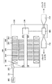
ここで、まず図1と図2とを用いて、後述する各実施の形態に記載のモータジェネレータ(回転電機)を搭載可能なハイブリッド車両1の構成例について説明する。図1は、下記の各実施の形態におけるモータジェネレータを搭載可能なハイブリッド車両の構成例を示す概略図である。図2は、図1に示すモータジェネレータとその近傍の概略構成を示す図である。 Here, first, a configuration example of the hybrid vehicle 1 on which a motor generator (rotary electric machine) described in each embodiment described later can be mounted will be described with reference to FIGS. 1 and 2. FIG. 1 is a schematic diagram illustrating a configuration example of a hybrid vehicle in which a motor generator in each of the following embodiments can be mounted. FIG. 2 is a diagram showing a schematic configuration of the motor generator shown in FIG. 1 and the vicinity thereof.
なお、図1に示すハイブリッド車両1はFF(Front engine Front wheel drive)方式の車両であるが、下記の各実施の形態におけるモータジェネレータは、このFF方式のハイブリッド車両のみならずFR(Front engine Rear wheel drive)方式のハイブリッド車両にも適用可能である。FR方式の場合には、一般にエンジン等の配置や、前方のエンジンからプロペラシャフトを介して後輪に動力を伝達する点でFF方式の車両とは構成が若干異なるが、それ以外の基本的な構成は類似しており、またFR方式のハイブリッド車両の構成も周知であるので、本願明細書においては、FR方式のハイブリッド車両についての説明は省略する。 The hybrid vehicle 1 shown in FIG. 1 is a front engine front wheel drive (FF) type vehicle, but the motor generator in each of the following embodiments is not limited to this hybrid vehicle of the FF type but also an FR (Front engine Rear). It can also be applied to a hybrid vehicle using a wheel drive system. In the case of the FR system, the configuration is slightly different from that of the FF system in that the engine is generally arranged and power is transmitted from the front engine to the rear wheels via the propeller shaft. Since the configuration is similar and the configuration of the FR hybrid vehicle is well known, the description of the FR hybrid vehicle is omitted in this specification.
図1に示すように、ハイブリッド車両1は、エンジン100と、モータジェネレータ200と、PCU(Power Control Unit)300と、バッテリ400と、動力分割機構500と、ディファレンシャル機構600と、ドライブシャフト700と、前輪である駆動輪800L,800Rとを備える。
As shown in FIG. 1, the hybrid vehicle 1 includes an
図1の例では、エンジン100と、モータジェネレータ200と、PCU300と、動力分割機構500は、エンジンルーム900内に配設される。PCU300は、カウルと前輪のサスペンションとの間の車両側部に設けられる。モータジェネレータ200とPCU300とは、ケーブル3Aにより接続される。PCU300とバッテリ400とは、ケーブル3Bにより接続される。また、エンジン100とモータジェネレータ200からなる動力出力装置は、動力分割機構500を介してディファレンシャル機構600に連結されている。ディファレンシャル機構600は、ドライブシャフト700を介して駆動輪800L,800Rに連結されている。
In the example of FIG. 1,
モータジェネレータ200は、3相交流同期電動発電機であって、PCU300から受ける交流電力によって駆動力を発生する。また、モータジェネレータ200は、ハイブリッド車両1の減速時等においては発電機としても使用され、その発電作用(回生発電)により交流電力を発電し、その発電した交流電力をPCU300へ出力する。
PCU300は、バッテリ400から受ける直流電圧を交流電圧に変換してモータジェネレータ200を駆動制御する。このPCU300は、モータジェネレータ200が発電した交流電圧を直流電圧に変換してバッテリ400を充電する。動力分割機構500は、たとえばプラネタリギヤ(図示せず)等の各種要素を組合せて構成される。
エンジン100および/またはモータジェネレータ200から出力された動力は、動力分割機構500からディファレンシャル機構600を介してドライブシャフト700に伝達される。そして、ドライブシャフト700に伝達された駆動力は、駆動輪800L,800Rに回転力として伝達されて、車両を走行させることができる。この場合、モータジェネレータ200は電動機として作動する。
The power output from
他方、車両の減速時等においては、駆動輪800L,800Rあるいはエンジン100によってモータジェネレータ200が駆動される。この場合には、モータジェネレータ200が発電機として作動する。このモータジェネレータ200により発電された電力は、PCU300内のインバータを介してバッテリ400に蓄えられる。
On the other hand, when the vehicle is decelerated, the
次に、図2を用いて、モータジェネレータ200とその近傍の構成について少し詳しく説明する。
Next, the configuration of the
モータジェネレータ200は、上述のように電動機または発電機としての機能を有する回転電機であり、軸受230を介してハウジング210に回転可能に取付けられた回転軸240と、回転軸240に取付けられたロータ(回転子)250と、ステータ(固定子)260とを有する。
The
ステータ260はステータコア261を有し、ステータコア261にはステータコイル(コイル巻線)が巻回されている。この巻回されたステータコイルの端部であるコイルエンド262は、バスバー(接続導体部あるいは導出部)8を介してハウジング210に設けられた給電用端子台(コネクタ)220と電気的に接続される。給電用端子台220は、給電ケーブル3Aを介してPCU300と電気的に接続される。PCU300は、図1に示すように給電ケーブル3Bを介してバッテリ400と電気的に接続されるので、PCU300と給電ケーブル3A,3Bとを介してバッテリ400とコイル262とが電気的に接続されることとなる。
The
上記のモータジェネレータ200は、図2に示すように、減速機構270を介してディファレンシャル機構600と接続され、ディファレンシャル機構600は、ドライブシャフト受け部710を介してドライブシャフト700と接続される。よって、モータジェネレータ200から出力された動力は、減速機構270、ディファレンシャル機構600およびドライブシャフト受け部710を介してドライブシャフト700に伝達されることとなる。
As shown in FIG. 2, the
(実施の形態1)
次に、図3〜図6を用いて、本発明の実施の形態1におけるモータジェネレータ(回転電機)200の構造例について説明する。図3は、本実施の形態1における、ステータコア261の構造例を示す平面図である。
(Embodiment 1)
Next, a structural example of the motor generator (rotating electric machine) 200 according to the first embodiment of the present invention will be described with reference to FIGS. FIG. 3 is a plan view showing a structural example of the
図3に示すように、ステータコア261は、環状の形状を有し、たとえば電磁鋼板のような複数の板状磁性材料を積層してかしめることによって形成することができる。なお、ステータコア261を磁性材料からなる一体の部材で構成してもよい。
As shown in FIG. 3, the
図3の例では、ステータコア261は、内周に、その径方向内方に突出する複数(図3の例では12個)のティース(凸部)261aと、ティース261a間に複数(図3の例では12個)のスロット(凹部:溝部)264と、ステータコア261を固定するための複数の固定用孔265とを有する。
In the example of FIG. 3, the
ティース261aの各々には、ステータコイルが集中巻によって巻回される。本実施の形態1では、ステータコイルは、樹脂等の絶縁材料を用いてモジュール化(ユニット化)されているので、このモジュール化されたステータコイルモジュール(カセットコイル)をティース261aに装着することとなる。この場合、ステータコイルは、上記の絶縁材料を介して各ティース261aに巻回されることとなる。
A stator coil is wound around each of the
上記のようにステータコイルモジュールをステータコア261のティース261aに装着することで、ティース261a間のスロット264は、ステータコイルモジュールの一部で実質的に充填されることとなる。このようにティース261aに巻回されたステータコイルに電流を流すことによって、流された電流の方向に応じた磁界が発生する。
By attaching the stator coil module to the
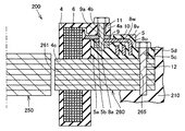
図4は、本実施の形態1におけるモータジェネレータ(回転電機)200の部分断面図である。 FIG. 4 is a partial cross-sectional view of motor generator (rotary electric machine) 200 according to the first embodiment.
図4に示すように、ステータ260は、ステータコア261と、ロータ250側に位置する内側樹脂部品(コイル構成部品:第1樹脂部)4のような内側絶縁体部品と、ステータ260の外周側に位置する外側樹脂部品(リード構成部品:第2樹脂部)5のような外側絶縁体部品とを有する。内側樹脂部品4は、固定部材により外側樹脂部品5と固定される。図4の例では、固定部材としてボルト11とナット10を例示している。なお、各樹脂部品は、典型的には、エポキシ樹脂のようにモールド成形可能な樹脂材料を用いて成形されるが、たとえばセラミックのような樹脂以外の絶縁材料を用いて内側部品や外側部品を作製してもよい。
As shown in FIG. 4, the
内側樹脂部品4は、内部にステータコイル6と、外側樹脂部品5と重なるように突出する突出部(張出部)4aと、ボルト11を受入れ可能な貫通孔4bと、ステータコア261のティースを受入れ可能な貫通孔4cと、コイル側バスバー(接続導体部)9とを有する。
The
コイル側バスバー9は、ステータコイル6と電気的に接続され、ステータコイル6を内側樹脂部品4の外部に導出する。図4の例では、内側樹脂部品4の突出部4aに沿うようにコイル側バスバー9を延在させ、該コイル側バスバー9の一部を内側樹脂部品4の表面に露出させることで、ステータコイル6の導出部(第1導出部)を設けている。より詳しくは、コイル側バスバー9の一部を、内側樹脂部品4の突出部4aにおける外側樹脂部品5側の表面に沿って延在させ、突出部4aと外側樹脂部品5との間に配置する。また、コイル側バスバー9は、ボルト11を受入れ可能な貫通孔9aを有する。
The coil-
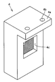
図5に、内側樹脂部品4の構造例を示す。図5の例では、内側樹脂部品4は、略L形の側面形状を有しており、一方の端部から張出すように突出部4aが設けられる。この突出部4aには、複数(図5の例では2つ)の貫通孔4bが設けられる。また、内側樹脂部品4の長手方向(図5の上下方向)の中央部あるいはその近傍には、上述の貫通孔4cが設けられる。
In FIG. 5, the structural example of the inner
他方、外側樹脂部品5は、ステータコア261に固定される。図4の例では、ステータコア261の径方向(図4の左右方向)における外側樹脂部品5の一方の端部(外側端部)近傍に設けた貫通孔5cにボルト12を挿着し、該ボルト12を用いて外側樹脂部品5をステータコア261に固定している。しかし、ボルト12以外の固定部材や固定手段を用いて外側樹脂部品5をステータコア261に固定してもよい。
On the other hand, the
また、図4の例では、ロータ250とステータ260とを収容可能なハウジング(筐体)210に達するように上記のボルト12をステータコア261の固定用孔265に挿通し、ボルト12を用いてステータコア261をハウジング210にも固定している。
In the example of FIG. 4, the
外側樹脂部品5は、ステータコイル6と電気的に接続されるリード側バスバー(接続導体部)8u,8v,8wを内部に有する。各リード側バスバー8u,8v,8wは、図4に示すように互いに間隔をあけて外側樹脂部品5内に配設され、ステータコア261の周方向にずれた位置でそれぞれ外側樹脂部品5の外部に導出され、この導出部にボルト11を受入れ可能な貫通孔を有する。また、各リード側バスバー8u,8v,8wは、たとえば上述の給電用端子台220等のコネクタを介してPCU300と電気的に接続される。
The
図4の断面では、リード側バスバー8uが外側樹脂部品5の外部に導出されており、このリード側バスバー8uの導出部(第2導出部)にボルト11を受入れ可能な貫通孔8aを設けている。リード側バスバー8uの導出部は、図4に示すように、コイル側バスバー9の導出部と対向する位置に配置することが好ましい。
In the cross section of FIG. 4, the lead-
また、外側樹脂部品5は、ステータコア261の径方向(図4の左右方向)における他方の端部(内側端部)5a近傍に凹部5bを有する。この凹部5b内には上述のナット10が設置される。このナット10上に、上記のリード側バスバー8uの導出部を延在させる。
The
図6に、外側樹脂部品5の構造例を示す。図6の例では、外側樹脂部品5は、ステータコア261と同様の平面形状、つまり環状の平面形状を有しており、上面には段差部が設けられている。外側樹脂部品5の内側の端部5a近傍においてリード側バスバー8uの導出部が露出しており、この露出した導出部に上述の貫通孔8aを設ける。また、外側樹脂部品5の外周から外方に突出するように突出部5dを設け、この突出部5dに上述の貫通孔5cを設ける。
In FIG. 6, the structural example of the outer
上記のような構造のステータ260を作製するには、たとえばステータコイル6とコイル側バスバー9とを接続した状態でインサート成形(モールド成形)を行なうことで内側樹脂部品4を作製し、同様にインサート成形により外側樹脂部品5を別途作製する。そして、内側樹脂部品4と組合せるように外側樹脂部品5をステータコア261に装着し、ボルト11,12を取付けるだけでよい。なお、インサート成形により内側樹脂部品4と外側樹脂部品5とをそれぞれ成形し、これらをステータコア261に装着するようにしてもよい。
In order to manufacture the
上記のようにボルト11,12のような固定部材を取付けるだけで内側樹脂部品4と外側樹脂部品5とを固定することができるので、内側樹脂部品4と外側樹脂部品5とを容易に固定することができる。このとき、内側樹脂部品4がステータコイル6を内部に有しており、外側樹脂部品5がステータコア261に固定されているので、ステータコイル6を有するコイルモジュールを、ステータコア261に容易に固定することができる。
Since the
また、本実施の形態1の場合、ボルト11によりリード側バスバー8uとコイル側バスバー9をも同時に接続することができるので、ステータコイル6とリード側バスバー8uとの結線をも同時に行なえ、両者を電気的に接続することもできる。したがって、該結線工程のタクトタイムの短縮も図れる。
In the case of the first embodiment, the lead-
さらに、ボルト11のように締付可能な固定部材を使用することで、リード側バスバー8uとコイル側バスバー9の一方を他方に強く当接することができる。また、これらの上下に樹脂部を設けた場合には、リード側バスバー8uとコイル側バスバー9の接続部を補強することができ、接続部の信頼性をも向上することができる。
Furthermore, by using a fastening member that can be tightened, such as the bolt 11, one of the lead-
その上、内側樹脂部品4や外側樹脂部品5のような樹脂成形品を採用することで熱伝導性をも良好なものとすることができる。また、図4の例のように内側樹脂部品4と外側樹脂部品5の端面同士を当接することも熱伝導性向上に寄与し得る。よって、放熱特性をも良好なものとすることができる。
In addition, by adopting a resin molded product such as the
なお、上述の実施の形態1では、内側樹脂部品4にボルト11の軸部を受入れる貫通孔4aを設け、外側樹脂部品5にボルト11が螺着されるナット10を設置したが、ボルト11の軸部を受入れる貫通孔と、ナットとは、内側樹脂部品4と外側樹脂部品5のいずれに設置してもよい。また、ボルト11やナット10の取付位置も上記以外の任意の位置を選択可能である。
In the above-described first embodiment, the
さらに、リード側バスバーとコイル側バスバーにボルト挿通用の貫通孔を設けず、内側樹脂部品4と外側樹脂部品5とを固定した際に、リード側バスバーとコイル側バスバーとを当接させるだけの構成も採用可能である。また、リード側バスバーとコイル側バスバーとの間に、たとえば両者よりも硬度の低い導電部材を挿入する等して、これらの間の実質的な接触面積を増大させ、接続抵抗を低減することも考えられる。
Furthermore, when the inner
また、内側樹脂部品4と外側樹脂部品5の形状についても任意に変形可能である。たとえば内側樹脂部品4に凹部を設け、外側樹脂部品5に凸部を設け、内側樹脂部品4の凹部に外側樹脂部品5の凸部を嵌合する等して、両者を互いに係合あるいは連結するとともに両者の接触面積を増大させることも考えられる。
Further, the shapes of the
(実施の形態2)
次に、図7と図8を用いて、本発明の実施の形態2について説明する。
(Embodiment 2)
Next, Embodiment 2 of the present invention will be described with reference to FIGS.
上述の実施の形態1では、内側樹脂部品4と外側樹脂部品5とを固定するための固定部材としてボルト11とナット10とを例示したが、これら以外の固定部材や固定手段を使用することも可能である。
In the above-described first embodiment, the bolt 11 and the
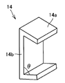
たとえば図7および図8に示すように、コの字状のクランプ具14を採用することも可能である。図7および図8に示すように、クランプ具14は両端に挟持部(クランプ部)14aを有しており、この挟持部14aで、リード側バスバー8uとコイル側バスバー9とを、直接あるいは間接的に挟持することにより、リード側バスバー8uとコイル側バスバー9とを固定するとともに、内側樹脂部品4と外側樹脂部品5とを固定することもできる。
For example, as shown in FIGS. 7 and 8, a
このとき、外側樹脂部品5の端部5a近傍に設けた凹部5bの深さを、クランプ具14の一端に設けた挟持部14aの厚みよりも深くし、凹部5bの幅(ステータコア261の径方向における幅:図7の左右方向の幅)を、クランプ具14の一端側の挟持部14aの幅よりも狭くすることにより、クランプ具14を容易に装着することができる。
At this time, the depth of the
図8に示すように、クランプ具14の挟持部14aと本体部14bとのなす角度θは、典型的には鋭角となるようにしておく。それにより、クランプ具14を各樹脂部品やバスバーに装着した際に、これらに対し力を作用させることができる。たとえば、図7の例では、内側樹脂部品4の突出部4aと、リード側バスバー8uと、コイル側バスバー9とが互いに強固に当接するような力を作用させることができる。
As shown in FIG. 8, the angle θ formed between the clamping
なお、クランプ具14の構成も、内側樹脂部品4と外側樹脂部品5とを固定することができるものであれば、図7や図8に示すものに限らず任意に選択可能である。また、図7の例では、内側樹脂部品4の突出部4aと、リード側バスバー8uと、コイル側バスバー9とを固定する場合について説明したが、内側樹脂部品4と外側樹脂部品5の少なくとも一方の一部とともにリード側バスバー8uとコイル側バスバー9とを固定するようにしてもよく、クランプ具14によってリード側バスバー8uとコイル側バスバー9とを直接固定するようにしてもよい。また、クランプ具14の材質としては、典型的には金属等が考えられるが、弾性変形可能な材料であれば金属以外の材料を採用可能である。
The configuration of the
以上のように本発明の実施の形態について説明を行なったが、上述の各実施の形態の構成を適宜組合せることも当初から予定している。また、今回開示した実施の形態はすべての点での例示であって制限的なものではないと考えられるべきである。本発明の範囲は特許請求の範囲によって示され、特許請求の範囲と均等の意味および範囲内でのすべての変更が含まれる。 Although the embodiments of the present invention have been described as described above, it is also planned from the beginning to appropriately combine the configurations of the above-described embodiments. Further, it should be considered that the embodiment disclosed this time is illustrative in all points and not restrictive. The scope of the present invention is defined by the terms of the claims, and includes meanings equivalent to the terms of the claims and all modifications within the scope.
1 ハイブリッド車両、3,3A,3B ケーブル、4 内側樹脂部品、4a,5d 突出部、4b,4c,5c,8a,9a 貫通孔、5 外側樹脂部品、5a 端部、5b 凹部、6 ステータコイル、8,8u,8v,8w リード側バスバー、9 コイル側バスバー、10 ナット、11,12 ボルト、14 クランプ具、14a 挟持部、14b 本体部、100 エンジン、200 モータジェネレータ、210 ハウジング、220 給電用端子台、230 軸受、240 回転軸、250 ロータ、260 ステータ、261 ステータコア、262 コイルエンド、270 減速機構、300 PCU、400 バッテリ、500 動力分割機構、600 ディファレンシャル機構、700 ドライブシャフト、710 ドライブシャフト受け部、800L,800R 駆動輪、900 エンジンルーム。 DESCRIPTION OF SYMBOLS 1 Hybrid vehicle, 3, 3A, 3B cable, 4 Inner resin parts, 4a, 5d Protrusion part, 4b, 4c, 5c, 8a, 9a Through hole, 5 Outer resin part, 5a End part, 5b Recessed part, 6 Stator coil, 8, 8u, 8v, 8w Lead side bus bar, 9 Coil side bus bar, 10 Nut, 11, 12 bolt, 14 Clamping tool, 14a Clamping part, 14b Body part, 100 Engine, 200 Motor generator, 210 Housing, 220 Power supply terminal Table, 230 Bearing, 240 Rotating shaft, 250 Rotor, 260 Stator, 261 Stator core, 262 Coil end, 270 Deceleration mechanism, 300 PCU, 400 Battery, 500 Power split mechanism, 600 Differential mechanism, 700 Drive shaft, 710 Drive shaft receiver , 800L, 800R drive wheels, 900 engine room.
Claims (6)
前記ステータは、ステータコアと、ステータコイルと一体に固定された第1絶縁体と、前記ステータコアに固定された第2絶縁体とを含み、
固定部材を用いて、前記第1絶縁体と前記第2絶縁体とを固定した、回転電機。 A rotor and a stator,
The stator includes a stator core, a first insulator fixed integrally with the stator coil, and a second insulator fixed to the stator core,
A rotating electrical machine in which the first insulator and the second insulator are fixed using a fixing member.
前記固定部材を用いて、前記第1樹脂部と前記第2樹脂部とを固定した、請求項1に記載の回転電機。 The first insulator includes a first resin portion; the second insulator includes a second resin portion;
The rotating electrical machine according to claim 1, wherein the first resin portion and the second resin portion are fixed using the fixing member.
前記第2樹脂部は、内部に前記ステータコイルと電気的に接続される接続導体部と、該接続導体部を前記第2樹脂部の外部に導出する第2導出部とを有し、
前記固定部材を用いて、前記第1導出部と前記第2導出部とを固定するとともに前記ステータコイルと前記接続導体部とを電気的に接続するようにした、請求項2に記載の回転電機。 The first resin portion has a first lead-out portion that leads the stator coil to the outside of the first resin portion,
The second resin portion includes a connection conductor portion that is electrically connected to the stator coil inside, and a second lead-out portion that leads the connection conductor portion to the outside of the second resin portion,
The rotating electrical machine according to claim 2, wherein the fixing member is used to fix the first lead-out part and the second lead-out part and to electrically connect the stator coil and the connection conductor part. .
前記突出部に沿うように前記第1導出部を配置し、
前記第1導出部と対向する位置に前記第2導出部を配置し、
前記第1導出部と前記第2導出部とが当接するように、前記固定部材により前記第1導出部と前記第2導出部とを固定した、請求項3に記載の回転電機。 The first resin portion has a protruding portion that protrudes so as to overlap the second resin portion,
Arranging the first lead-out portion along the projecting portion;
Arranging the second derivation unit at a position facing the first derivation unit;
The rotating electrical machine according to claim 3, wherein the first lead-out part and the second lead-out part are fixed by the fixing member so that the first lead-out part and the second lead-out part come into contact with each other.
前記第1と第2樹脂部の一方に、前記ボルトの軸部を受入れる貫通孔を設け、
前記第1と第2樹脂部の他方に、前記ボルトが螺着される前記ナットを設置し、
前記ボルトを前記ナットに螺着することで、前記第1樹脂部と前記第2樹脂部とを固定した、請求項2から請求項4のいずれかに記載の回転電機。 The fixing member includes a bolt and a nut,
One of the first and second resin parts is provided with a through hole for receiving the shaft part of the bolt,
The nut on which the bolt is screwed is installed on the other of the first and second resin parts,
The rotating electrical machine according to any one of claims 2 to 4, wherein the first resin portion and the second resin portion are fixed by screwing the bolt to the nut.
Priority Applications (1)
| Application Number | Priority Date | Filing Date | Title |
|---|---|---|---|
| JP2006164996A JP2007336676A (en) | 2006-06-14 | 2006-06-14 | Electric rotating machine and vehicle |
Applications Claiming Priority (1)
| Application Number | Priority Date | Filing Date | Title |
|---|---|---|---|
| JP2006164996A JP2007336676A (en) | 2006-06-14 | 2006-06-14 | Electric rotating machine and vehicle |
Publications (1)
| Publication Number | Publication Date |
|---|---|
| JP2007336676A true JP2007336676A (en) | 2007-12-27 |
Family
ID=38935604
Family Applications (1)
| Application Number | Title | Priority Date | Filing Date |
|---|---|---|---|
| JP2006164996A Withdrawn JP2007336676A (en) | 2006-06-14 | 2006-06-14 | Electric rotating machine and vehicle |
Country Status (1)
| Country | Link |
|---|---|
| JP (1) | JP2007336676A (en) |
Cited By (1)
| Publication number | Priority date | Publication date | Assignee | Title |
|---|---|---|---|---|
| KR20190127003A (en) * | 2018-05-03 | 2019-11-13 | 현대모비스 주식회사 | Stator assembly for hairpin winding motor |
-
2006
- 2006-06-14 JP JP2006164996A patent/JP2007336676A/en not_active Withdrawn
Cited By (2)
| Publication number | Priority date | Publication date | Assignee | Title |
|---|---|---|---|---|
| KR20190127003A (en) * | 2018-05-03 | 2019-11-13 | 현대모비스 주식회사 | Stator assembly for hairpin winding motor |
| KR102566025B1 (en) * | 2018-05-03 | 2023-08-11 | 현대모비스 주식회사 | Stator assembly for hairpin winding motor |
Similar Documents
| Publication | Publication Date | Title |
|---|---|---|
| JP4743167B2 (en) | Terminal module for rotating electric machine and rotating electric machine | |
| US7312545B2 (en) | Controller for electric power steering and electric power steering system | |
| US7453179B2 (en) | DC brushless motor for electrical power steering and the production method thereof | |
| WO2007132934A1 (en) | Connecting structure for electric device and feeder terminal portion, and vehicle | |
| US7855484B2 (en) | Insulating member and stator | |
| JP2007312560A (en) | Insulator and rotary electric machine | |
| EP2701287B1 (en) | Rotating electric machine | |
| JP4811114B2 (en) | Stator fixing structure and vehicle | |
| JP2009056867A (en) | Brushless motor and electric power steering device | |
| JP5233417B2 (en) | Rotating electric machine | |
| JP2004153891A (en) | Rotary electric machine | |
| JP2006340580A (en) | Rotary electric machine | |
| JP2005229755A (en) | Motor module | |
| JP7172843B2 (en) | motor | |
| JP6281266B2 (en) | Terminal connection structure of rotating electrical machine | |
| CN109962575B (en) | Rotating electrical machine | |
| JP5387604B2 (en) | Terminal module for rotating electric machine and rotating electric machine | |
| JP2007336677A (en) | Electric rotating machine and vehicle | |
| JP2007336676A (en) | Electric rotating machine and vehicle | |
| JP2008312288A (en) | Stator and manufacturing method therefor, and rotary electric machine | |
| JP7095649B2 (en) | Terminal connection structure of rotary machine for vehicle drive | |
| JP2008289243A (en) | Fastening structure of bus bar | |
| JP2007221854A (en) | Stator fixing structure and electric vehicle | |
| JP5579241B2 (en) | Rotating electric machine | |
| JP2005229753A (en) | Motor module |
Legal Events
| Date | Code | Title | Description |
|---|---|---|---|
| A300 | Withdrawal of application because of no request for examination |
Free format text: JAPANESE INTERMEDIATE CODE: A300 Effective date: 20090901 |