EP3614240A1 - Capacitive stylus, touch device, and electronic system thereof - Google Patents
Capacitive stylus, touch device, and electronic system thereof Download PDFInfo
- Publication number
- EP3614240A1 EP3614240A1 EP19179841.2A EP19179841A EP3614240A1 EP 3614240 A1 EP3614240 A1 EP 3614240A1 EP 19179841 A EP19179841 A EP 19179841A EP 3614240 A1 EP3614240 A1 EP 3614240A1
- Authority
- EP
- European Patent Office
- Prior art keywords
- electrode
- capacitive stylus
- refill
- conductive
- touch device
- Prior art date
- Legal status (The legal status is an assumption and is not a legal conclusion. Google has not performed a legal analysis and makes no representation as to the accuracy of the status listed.)
- Withdrawn
Links
Images





Classifications
-
- G—PHYSICS
- G06—COMPUTING OR CALCULATING; COUNTING
- G06F—ELECTRIC DIGITAL DATA PROCESSING
- G06F3/00—Input arrangements for transferring data to be processed into a form capable of being handled by the computer; Output arrangements for transferring data from processing unit to output unit, e.g. interface arrangements
- G06F3/01—Input arrangements or combined input and output arrangements for interaction between user and computer
- G06F3/03—Arrangements for converting the position or the displacement of a member into a coded form
- G06F3/033—Pointing devices displaced or positioned by the user, e.g. mice, trackballs, pens or joysticks; Accessories therefor
- G06F3/0354—Pointing devices displaced or positioned by the user, e.g. mice, trackballs, pens or joysticks; Accessories therefor with detection of two-dimensional [2D] relative movements between the device, or an operating part thereof, and a plane or surface, e.g. 2D mice, trackballs, pens or pucks
- G06F3/03545—Pens or stylus
-
- G—PHYSICS
- G06—COMPUTING OR CALCULATING; COUNTING
- G06F—ELECTRIC DIGITAL DATA PROCESSING
- G06F3/00—Input arrangements for transferring data to be processed into a form capable of being handled by the computer; Output arrangements for transferring data from processing unit to output unit, e.g. interface arrangements
- G06F3/01—Input arrangements or combined input and output arrangements for interaction between user and computer
- G06F3/03—Arrangements for converting the position or the displacement of a member into a coded form
- G06F3/033—Pointing devices displaced or positioned by the user, e.g. mice, trackballs, pens or joysticks; Accessories therefor
- G06F3/038—Control and interface arrangements therefor, e.g. drivers or device-embedded control circuitry
- G06F3/0383—Signal control means within the pointing device
-
- G—PHYSICS
- G06—COMPUTING OR CALCULATING; COUNTING
- G06F—ELECTRIC DIGITAL DATA PROCESSING
- G06F3/00—Input arrangements for transferring data to be processed into a form capable of being handled by the computer; Output arrangements for transferring data from processing unit to output unit, e.g. interface arrangements
- G06F3/01—Input arrangements or combined input and output arrangements for interaction between user and computer
- G06F3/03—Arrangements for converting the position or the displacement of a member into a coded form
- G06F3/041—Digitisers, e.g. for touch screens or touch pads, characterised by the transducing means
- G06F3/0412—Digitisers structurally integrated in a display
-
- G—PHYSICS
- G06—COMPUTING OR CALCULATING; COUNTING
- G06F—ELECTRIC DIGITAL DATA PROCESSING
- G06F3/00—Input arrangements for transferring data to be processed into a form capable of being handled by the computer; Output arrangements for transferring data from processing unit to output unit, e.g. interface arrangements
- G06F3/01—Input arrangements or combined input and output arrangements for interaction between user and computer
- G06F3/03—Arrangements for converting the position or the displacement of a member into a coded form
- G06F3/041—Digitisers, e.g. for touch screens or touch pads, characterised by the transducing means
- G06F3/044—Digitisers, e.g. for touch screens or touch pads, characterised by the transducing means by capacitive means
-
- G—PHYSICS
- G06—COMPUTING OR CALCULATING; COUNTING
- G06F—ELECTRIC DIGITAL DATA PROCESSING
- G06F3/00—Input arrangements for transferring data to be processed into a form capable of being handled by the computer; Output arrangements for transferring data from processing unit to output unit, e.g. interface arrangements
- G06F3/01—Input arrangements or combined input and output arrangements for interaction between user and computer
- G06F3/048—Interaction techniques based on graphical user interfaces [GUI]
- G06F3/0487—Interaction techniques based on graphical user interfaces [GUI] using specific features provided by the input device, e.g. functions controlled by the rotation of a mouse with dual sensing arrangements, or of the nature of the input device, e.g. tap gestures based on pressure sensed by a digitiser
- G06F3/0488—Interaction techniques based on graphical user interfaces [GUI] using specific features provided by the input device, e.g. functions controlled by the rotation of a mouse with dual sensing arrangements, or of the nature of the input device, e.g. tap gestures based on pressure sensed by a digitiser using a touch-screen or digitiser, e.g. input of commands through traced gestures
- G06F3/04883—Interaction techniques based on graphical user interfaces [GUI] using specific features provided by the input device, e.g. functions controlled by the rotation of a mouse with dual sensing arrangements, or of the nature of the input device, e.g. tap gestures based on pressure sensed by a digitiser using a touch-screen or digitiser, e.g. input of commands through traced gestures for inputting data by handwriting, e.g. gesture or text
Definitions
- the present invention relates to a capacitive stylus, a touch device, and an electronic system according to the pre-characterizing clauses of claims 1, 15 and 18.
- the capacitive stylus includes a non-conductive nib, a first electrode and a second electrode and a control circuit.
- the first electrode and a second electrode are respectively arranged at different longitudinal positions of the capacitive stylus.
- the control circuit is coupled to the first electrode and the second electrode, and is configured to control the first electrode to generate a first signal and control the second electrode to generate a second signal, for a touch device to determine the location of the non-conductive nib on the touch device according to the first signal and the second signal.
- the touch device which is used with a capacitive stylus having a non-conductive nib and a first electrode and a second electrode arranged at different longitudinal positions of the capacitive stylus.
- the touch device comprises a receiving unit and a location determining unit.
- the receiving unit is used for receiving a first signal generated by the first electrode and a second signal generated by the second electrode.
- the location determining unit is coupled to the receiving unit, and is arranged for determining a location of the non-conductive nib on the touch device according to the first signal and the second signal.
- the electronic system which comprises a capacitive stylus and a touch device.
- the capacitive stylus comprises: a non-conductive nib; a first electrode and a second electrode, respectively arranged at different longitudinal positions of the capacitive stylus; and a control circuit, coupled to the first electrode and the second electrode, the control circuit configured to control the first electrode to generate a first signal and control the second electrode to generate a second signal.
- the touch device is arranged for determining a location of the non-conductive nib on the touch device according to the first signal and the second signal.
- FIG. 1 is a diagram illustrating a capacitive stylus 100 according to an embodiment of the present invention.
- the capacitive stylus 100 comprises a non-conductive nib 110, a non-conductive refill 120, a first electrode 130, a second electrode 140 and a control circuit 150.
- the non-conductive nib 110 and the non-conductive refill 120 are in one-piece, that is, the non-conductive nib 110 may be the end part of the non-conductive refill 120, but the present invention is not limited thereto.
- control circuit 150 is configured to control the first electrode 130 to generate a first signal, and control the control second electrode 140 to generate a second signal, for a touch device to determine the location of the non-conductive nib 110 on the touch device according to the first signal and second signal.
- the touch device calculates the location of the non-conductive nib 110 on the touch device by detecting signals generated from the first electrode 130 and the second electrode 140, rather than exerting voltage on the non-conductive nib 110 for the touch device to detect the location of the non-conductive nib 110 on the touch device.
- the control circuit 150 may exert the same frequency and the same voltage (e.g. 200 KHz and 20 Volt) onto the first electrode 130 and the second electrode 140, or exert different voltages (e.g. 20 Volt and 40 Volt) or different frequency (e.g. 200 KHz and 250 KHz) on to the first electrode 130 and the second electrode 140.
- the first electrode 130 and the second electrode 140 are arranged at different longitudinal positions of the capacitive stylus 100, and the first electrode 130 and the second electrode 140 may be designed in ring-shaped electrodes, columnar electrodes or any other shaped electrodes.
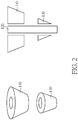
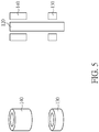
- FIGs. 2-5 illustrate the first electrode 130 and the second electrode 140 the embodiments of the present invention. As shown in the embodiment of FIG. 2 , both the first electrode 130 and the second electrode 140 are cone-ring shaped electrodes, and the first electrode 130 and the second electrode 140 circulate the non-conductive refill 120. As shown in the embodiment of FIG.
- the first electrode 130 is a cone-ring shaped electrode
- the second electrode 140 is columnar-ring shaped electrode
- the first electrode 130 and the second electrode 140 circulate the non-conductive refill 120.
- both the first electrode 130 and the second electrode 140 are columnar-ring shaped electrode
- the first electrode 130 and the second electrode 140 circulate the non-conductive refill 120.
- the first electrode 130 is implemented in columnar-ring shaped electrode with a higher height
- second electrode 140 is implemented in a columnar-ring shaped electrode with lower height
- the first electrode 130 and the second electrode 140 circulate the non-conductive refill 120.
- first electrode 130 and the second electrode 140 may circulate the non-conductive refill 120 in an incomplete manner, or the first electrode 130 and the second electrode 140 may be solid electrodes.
- the shape of electrodes can be modified according to actual design requirements, and these design modifications shall fall within the scope of the present invention.
- the capacitive stylus 100 in this embodiment generates signal via the first electrode 130 and the second electrode 140 for the touch device to determine the location of the non-conductive nib 110 on the touch device, which greatly improves the design flexibility of the non-conductive nib 110 and/or the non-conductive refill 120, e.g. general writing tools may be used cooperatively to reach both the analog and digital output functions.
- the non-conductive nib 110 and/or the non-conductive refill 120 may be pencil refill, roller pen refill, fluorescent refill, ball pen refill, plastic refill, whiteboard marker refill or any other writable refill.
- the user may write on a touch-detective whiteboard, wherein the whiteboard marker refill may leave traces on the whiteboard for the user to watch, and the detection circuit inside the whiteboard may also detect the moving trajectories of the non-conductive nib 110 on the whiteboard, to generate digital files (e.g. texts and picture files of patterns).
- digital files e.g. texts and picture files of patterns
- the user may place a blank paper on a drawing board (or writing board) with touch detective functions, wherein the pencil refill may leave traces on the blank paper for the user to watch, and the detection circuit of the drawing board (or writing board) may also detect the trajectories of the non-conductive nib 110 on the blank paper to generate digital file (e.g. texts and photo files of patterns on the bank paper).
- a drawing board or writing board
- touch detective functions wherein the pencil refill may leave traces on the blank paper for the user to watch
- the detection circuit of the drawing board (or writing board) may also detect the trajectories of the non-conductive nib 110 on the blank paper to generate digital file (e.g. texts and photo files of patterns on the bank paper).
- FIG. 6 is a diagram illustrating a touch device 610 which is used with a capacitive stylus having a non-conductive nib and a first electrode and a second electrode arranged at different longitudinal positions of the capacitive stylus (such as the aforementioned capacitive stylus 100) according to an embodiment of the present invention.
- the touch device 610 comprises a receiving unit 612 and a location determining unit 614.
- the receiving unit 612 is used for receiving a first signal generated by the first electrode and a second signal generated by the second electrode.
- the location determining unit 614 is coupled to the receiving unit, and is arranged for determining a location of the non-conductive nib on the touch device according to the first signal and the second signal.
- FIG. 7 is a diagram illustrating an electronic system 700 comprising a capacitive stylus (e.g. the capacitive stylus 100 mentioned in FIG. 1 ) and a touch device (e.g. the touch device 610 mentioned in FIG. 6 ) according to an embodiment of the present invention, wherein the touch device 610 is used to detect the location of a non-conductive nib 110.
- the touch device 610 may detect the first signal from the first electrode 130 and the second signal from the second electrode 140, and determine the projection coordinates (x1, y1) and (x2, y2) of the first electrode 130 and the second electrode 140 on the touch device 610 respectively.
- the calculation circuit inside the touch device 610 may use vector or trigonometric calculation methods to calculate the location (x0, y0) of the non-conductive nib 110 on the touch device 610 according to the distance D1 between the projection coordinates (x1, y1) and (x2, y2), the distance L0 between the non-conductive nib 110 and the first electrode 130, and the distance L1 between the first electrode 130 and second electrode 140.
- the touch device 610 may be a touch pad, touch screen, touch display, notebook, tablet, digital drawing board, digital writing board or any other electronic device capable of showing and recording the trajectories of the capacitive stylus 100 on the touch device 610.
- the capacitive stylus 100 contains the non-conductive refill 120 circulated by the first electrode 130 and the second electrode 140, but the non-conductive refill 120 is an optional element which may be removed from the capacitive stylus 100 without affecting the overall operation of the capacitive stylus 100. By removing the non-conductive refill 120, the capacitive stylus 100 may has a smaller diameter so that the capacitive stylus 100 can be inserted into the touch device 610.
- the capacitive stylus of the present invention is designed with two electrodes in order to generate signals for the touch device to perform trajectory detections.
- the refill of the capacitive stylus may be implemented in different refills to provide both the analog and digital output functions.
- some conventions combinations such as whiteboard pen and whiteboard, chalk and blackboard, crayon and drawing paper, pen and paper, pencil and sketchbook, may easily reach both analog and digital functions with the design of the capacitive stylus and touch device in embodiments of the present invention.
- the capacitive stylus since the material of the refills is not limited, the capacitive stylus may be implemented with a smaller refill to further reduce the diameter of the capacitive stylus.
Landscapes
- Engineering & Computer Science (AREA)
- General Engineering & Computer Science (AREA)
- Theoretical Computer Science (AREA)
- Human Computer Interaction (AREA)
- Physics & Mathematics (AREA)
- General Physics & Mathematics (AREA)
- Position Input By Displaying (AREA)
Abstract
A capacitive stylus (100) includes a non-conductive nib (110), a first electrode (130), a second electrode (140) and a control circuit (150). The first electrode (130) and the second electrode (140) are at different longitudinal positions of the capacitive stylus (100), and the control circuit (150) is configured to control the first electrode (130) to generate a first signal and control the second electrode (140) to generate a second signal, wherein the first signal and the second signal are used in a touch device (610) for determining a position of the nib (110).
Description
- The present invention relates to a capacitive stylus, a touch device, and an electronic system according to the pre-characterizing clauses of claims 1, 15 and 18.
- Related art capacitive styluses use the nib to preload a voltage, so that when the nib touches the touch device, the inner circuit of the touch device may detect the capacity variation between the nib and the touch device, so as to determine the location of the nib on the touch device. Since the capacitive stylus requires exerting voltage on the nib, the nib should be manufactured with conductive material, causing inconvenience of manufacturing and function limitations.
- This in mind, the application aims at providing a capacitive stylus, a touch device and associated electronic system in order to solve the problems mentioned above. This is achieved by a capacitive stylus, a touch device and an associated electronic system according to claims 1, 15 and 18. The dependent claims pertain to corresponding further developments and improvements.
- As will be seen more clearly from the detailed description following below, the capacitive stylus includes a non-conductive nib, a first electrode and a second electrode and a control circuit. The first electrode and a second electrode are respectively arranged at different longitudinal positions of the capacitive stylus. The control circuit is coupled to the first electrode and the second electrode, and is configured to control the first electrode to generate a first signal and control the second electrode to generate a second signal, for a touch device to determine the location of the non-conductive nib on the touch device according to the first signal and the second signal.
- As will be seen more clearly from the detailed description following below, the touch device which is used with a capacitive stylus having a non-conductive nib and a first electrode and a second electrode arranged at different longitudinal positions of the capacitive stylus. The touch device comprises a receiving unit and a location determining unit. The receiving unit is used for receiving a first signal generated by the first electrode and a second signal generated by the second electrode. The location determining unit is coupled to the receiving unit, and is arranged for determining a location of the non-conductive nib on the touch device according to the first signal and the second signal.
- As will be seen more clearly from the detailed description following below, the electronic system which comprises a capacitive stylus and a touch device. The capacitive stylus comprises: a non-conductive nib; a first electrode and a second electrode, respectively arranged at different longitudinal positions of the capacitive stylus; and a control circuit, coupled to the first electrode and the second electrode, the control circuit configured to control the first electrode to generate a first signal and control the second electrode to generate a second signal. The touch device is arranged for determining a location of the non-conductive nib on the touch device according to the first signal and the second signal.
- In the following, the invention is further illustrated by way of example, taking reference to the accompanying drawings. Thereof:
-
-
FIG. 1 is a diagram illustrating a capacitive stylus according to an embodiment of the present invention. -
FIG. 2 is a diagram illustrating a first electrode and second electrode according to a first embodiment of the present invention. -
FIG. 3 is a diagram illustrating a first electrode and second electrode according to a second embodiment of the present invention. -
FIG. 4 is a diagram illustrating a first electrode and second electrode according to a third embodiment of the present invention. -
FIG. 5 is a diagram illustrating a first electrode and second electrode according to a fifth embodiment of the present invention. -
FIG. 6 is a diagram illustrating atouch device 610 which is used with a capacitive stylus according to an embodiment of the present invention. -
FIG. 7 is a diagram illustrating an electronic system comprising a capacitive stylus and a touch device according to an embodiment of the present invention, wherein the touch device detects the location of a non-conductive nib. -
FIG. 1 is a diagram illustrating acapacitive stylus 100 according to an embodiment of the present invention. As shown inFIG. 1 , thecapacitive stylus 100 comprises anon-conductive nib 110, anon-conductive refill 120, afirst electrode 130, asecond electrode 140 and acontrol circuit 150. In this embodiment, thenon-conductive nib 110 and thenon-conductive refill 120 are in one-piece, that is, thenon-conductive nib 110 may be the end part of thenon-conductive refill 120, but the present invention is not limited thereto. - In this embodiment, the
control circuit 150 is configured to control thefirst electrode 130 to generate a first signal, and control the controlsecond electrode 140 to generate a second signal, for a touch device to determine the location of thenon-conductive nib 110 on the touch device according to the first signal and second signal. In other words, the touch device calculates the location of thenon-conductive nib 110 on the touch device by detecting signals generated from thefirst electrode 130 and thesecond electrode 140, rather than exerting voltage on thenon-conductive nib 110 for the touch device to detect the location of thenon-conductive nib 110 on the touch device. In an embodiment, thecontrol circuit 150 may exert the same frequency and the same voltage (e.g. 200 KHz and 20 Volt) onto thefirst electrode 130 and thesecond electrode 140, or exert different voltages (e.g. 20 Volt and 40 Volt) or different frequency (e.g. 200 KHz and 250 KHz) on to thefirst electrode 130 and thesecond electrode 140. - As shown in
FIG. 1 , thefirst electrode 130 and thesecond electrode 140 are arranged at different longitudinal positions of thecapacitive stylus 100, and thefirst electrode 130 and thesecond electrode 140 may be designed in ring-shaped electrodes, columnar electrodes or any other shaped electrodes.FIGs. 2-5 illustrate thefirst electrode 130 and thesecond electrode 140 the embodiments of the present invention. As shown in the embodiment ofFIG. 2 , both thefirst electrode 130 and thesecond electrode 140 are cone-ring shaped electrodes, and thefirst electrode 130 and thesecond electrode 140 circulate thenon-conductive refill 120. As shown in the embodiment ofFIG. 3 , thefirst electrode 130 is a cone-ring shaped electrode, and thesecond electrode 140 is columnar-ring shaped electrode, and thefirst electrode 130 and thesecond electrode 140 circulate thenon-conductive refill 120. As shown in the embodiment ofFIG. 4 , both thefirst electrode 130 and thesecond electrode 140 are columnar-ring shaped electrode, and thefirst electrode 130 and thesecond electrode 140 circulate thenon-conductive refill 120. In the embodiment ofFIG. 4 , considering the distance from thesecond electrode 140 to thenon-conductive nib 110 is relatively far, thefirst electrode 130 is implemented in columnar-ring shaped electrode with a higher height, andsecond electrode 140 is implemented in a columnar-ring shaped electrode with lower height, and thefirst electrode 130 and thesecond electrode 140 circulate thenon-conductive refill 120. - It should be noted that the fashions of the
first electrode 130 and thesecond electrode 140 shown inFIGS. 2-5 are merely for illustrative purposes, and are not meant to be limitations to the present invention. In other embodiments, thefirst electrode 130 and thesecond electrode 140 may circulate thenon-conductive refill 120 in an incomplete manner, or thefirst electrode 130 and thesecond electrode 140 may be solid electrodes. As long as thefirst electrode 130 and thesecond electrode 140 are positioned at different longitudinal locations of thecapacitive stylus 100, the shape of electrodes can be modified according to actual design requirements, and these design modifications shall fall within the scope of the present invention. - The
capacitive stylus 100 in this embodiment generates signal via thefirst electrode 130 and thesecond electrode 140 for the touch device to determine the location of thenon-conductive nib 110 on the touch device, which greatly improves the design flexibility of thenon-conductive nib 110 and/or thenon-conductive refill 120, e.g. general writing tools may be used cooperatively to reach both the analog and digital output functions. For example, thenon-conductive nib 110 and/or thenon-conductive refill 120 may be pencil refill, roller pen refill, fluorescent refill, ball pen refill, plastic refill, whiteboard marker refill or any other writable refill. Take the whiteboard marker refill as an example of thenon-conductive nib 110 and thenon-conductive refill 120, the user may write on a touch-detective whiteboard, wherein the whiteboard marker refill may leave traces on the whiteboard for the user to watch, and the detection circuit inside the whiteboard may also detect the moving trajectories of thenon-conductive nib 110 on the whiteboard, to generate digital files (e.g. texts and picture files of patterns). Further, take the pencil refill as an example of thenon-conductive nib 110 and thenon-conductive refill 120, the user may place a blank paper on a drawing board (or writing board) with touch detective functions, wherein the pencil refill may leave traces on the blank paper for the user to watch, and the detection circuit of the drawing board (or writing board) may also detect the trajectories of thenon-conductive nib 110 on the blank paper to generate digital file (e.g. texts and photo files of patterns on the bank paper). -
FIG. 6 is a diagram illustrating atouch device 610 which is used with a capacitive stylus having a non-conductive nib and a first electrode and a second electrode arranged at different longitudinal positions of the capacitive stylus (such as the aforementioned capacitive stylus 100) according to an embodiment of the present invention. Thetouch device 610 comprises areceiving unit 612 and alocation determining unit 614. Thereceiving unit 612 is used for receiving a first signal generated by the first electrode and a second signal generated by the second electrode. Thelocation determining unit 614 is coupled to the receiving unit, and is arranged for determining a location of the non-conductive nib on the touch device according to the first signal and the second signal. -
FIG. 7 is a diagram illustrating anelectronic system 700 comprising a capacitive stylus (e.g. thecapacitive stylus 100 mentioned inFIG. 1 ) and a touch device (e.g. thetouch device 610 mentioned inFIG. 6 ) according to an embodiment of the present invention, wherein thetouch device 610 is used to detect the location of anon-conductive nib 110.. As shown inFIG. 7 , thetouch device 610 may detect the first signal from thefirst electrode 130 and the second signal from thesecond electrode 140, and determine the projection coordinates (x1, y1) and (x2, y2) of thefirst electrode 130 and thesecond electrode 140 on thetouch device 610 respectively. Next, since the distance L0 between thenon-conductive nib 110 and thefirst electrode 130 and the distance L1 between thefirst electrode 130 and thesecond electrode 140 are known, the calculation circuit inside thetouch device 610 may use vector or trigonometric calculation methods to calculate the location (x0, y0) of thenon-conductive nib 110 on thetouch device 610 according to the distance D1 between the projection coordinates (x1, y1) and (x2, y2), the distance L0 between thenon-conductive nib 110 and thefirst electrode 130, and the distance L1 between thefirst electrode 130 andsecond electrode 140. - In some embodiments, the
touch device 610 may be a touch pad, touch screen, touch display, notebook, tablet, digital drawing board, digital writing board or any other electronic device capable of showing and recording the trajectories of thecapacitive stylus 100 on thetouch device 610. - In the above embodiments, the
capacitive stylus 100 contains thenon-conductive refill 120 circulated by thefirst electrode 130 and thesecond electrode 140, but thenon-conductive refill 120 is an optional element which may be removed from thecapacitive stylus 100 without affecting the overall operation of thecapacitive stylus 100. By removing the non-conductiverefill 120, thecapacitive stylus 100 may has a smaller diameter so that thecapacitive stylus 100 can be inserted into thetouch device 610. - To summarize the present invention, the capacitive stylus of the present invention is designed with two electrodes in order to generate signals for the touch device to perform trajectory detections. Hence, the refill of the capacitive stylus may be implemented in different refills to provide both the analog and digital output functions. For example, some conventions combinations, such as whiteboard pen and whiteboard, chalk and blackboard, crayon and drawing paper, pen and paper, pencil and sketchbook, may easily reach both analog and digital functions with the design of the capacitive stylus and touch device in embodiments of the present invention. On the other hand, since the material of the refills is not limited, the capacitive stylus may be implemented with a smaller refill to further reduce the diameter of the capacitive stylus.
Claims (16)
- A capacitive stylus (100), characterized by:a non-conductive nib (110);a first electrode (130) and a second electrode (140), respectively arranged at different longitudinal positions of the capacitive stylus (100); anda control circuit (150), coupled to the first electrode (130) and the second electrode (140), the control circuit (150) configured to control the first electrode (130) to generate a first signal and control the second electrode (140) to generate a second signal, for a touch device (610) to determine a location of the non-conductive nib (110) on the touch device (610) according to the first signal and the second signal.
- The capacitive stylus (100) of claim 1, characterized in that the first electrode (130) is a columnar electrode, and the second electrode (140) is a ring-shaped electrode.
- The capacitive stylus (100) of claim 1, characterized in that the first electrode (130) is a columnar electrode, and the second electrode (140) is a columnar electrode.
- The capacitive stylus (100) of claim 1, characterized in that the first electrode (130) is a ring-shaped electrode, and the second electrode (140) is a columnar electrode.
- The capacitive stylus (100) of claim 1, characterized in that the first electrode (130) is a ring-shaped electrode, and the second electrode (140) is a ring-shaped electrode.
- The capacitive stylus (100) of claim 5, further characterized by:a non-conductive refill (120);wherein both the first electrode (130) and the second electrode (140) encircle the non-conductive refill (120).
- The capacitive stylus (100) of claim 6, characterized in that the first electrode (130) is a cone-ring shaped electrode, and the second electrode (140) is a cone-ring shaped electrode.
- The capacitive stylus (100) of claim 6, characterized in that the first electrode (130) is a cone-ring shaped electrode, and the second electrode (140) is a columnar-ring shaped electrode.
- The capacitive stylus (100) of claim 6, characterized in that the first electrode (130) is a columnar-ring shaped electrode, and the second electrode (140) is a cone-ring shaped electrode.
- The capacitive stylus (100) of claim 6, characterized in that the first electrode (130) is a columnar-ring shaped electrode, and the second electrode (140) is a columnar-ring shaped electrode.
- The capacitive stylus (100) of claim 6, characterized in that the non-conductive nib (110) and the non-conductive refill (120) are in one-piece.
- The capacitive stylus (100) of claim 1, characterized in that the first signal and the second signal have the same frequency and voltage.
- The capacitive stylus (100) of claim 1, further characterized by:
a non-conductive refill (120), wherein the non-conductive refill (120) is a pencil refill, roller pen refill, fluorescent refill, ball pen refill, plastic refill or whiteboard marker refill. - The capacitive stylus (100) of claim 13, characterized in that both the first electrode (130) and the second electrode (140) are ring-shaped electrodes, and encircle the non-conductive refill.
- A touch device (610), used with a capacitive stylus (100) having a non-conductive nib (110) and a first electrode (130) and a second electrode (140) arranged at different longitudinal positions of the capacitive stylus (100), the touch device (610) characterized by:a receiving unit (612), for receiving a first signal generated by the first electrode (130) and a second signal generated by the second electrode (140); anda location determining unit (614), coupled to the receiving unit (612), for determining a location of the non-conductive nib (110) on the touch device (610) according to the first signal and the second signal.
- The touch device (610) of claim 15, further characterized by:
a calculation circuit, for using a vector or trigonometric calculation method to calculate the location of the non-conductive nib (110) on the touch device (610) according to the distance between projection coordinates.
Applications Claiming Priority (1)
| Application Number | Priority Date | Filing Date | Title |
|---|---|---|---|
| TW107211485U TWM570464U (en) | 2018-08-22 | 2018-08-22 | Capacitive stylus |
Publications (1)
| Publication Number | Publication Date |
|---|---|
| EP3614240A1 true EP3614240A1 (en) | 2020-02-26 |
Family
ID=65035507
Family Applications (1)
| Application Number | Title | Priority Date | Filing Date |
|---|---|---|---|
| EP19179841.2A Withdrawn EP3614240A1 (en) | 2018-08-22 | 2019-06-13 | Capacitive stylus, touch device, and electronic system thereof |
Country Status (4)
| Country | Link |
|---|---|
| US (1) | US20200064936A1 (en) |
| EP (1) | EP3614240A1 (en) |
| CN (1) | CN110858105A (en) |
| TW (1) | TWM570464U (en) |
Families Citing this family (5)
| Publication number | Priority date | Publication date | Assignee | Title |
|---|---|---|---|---|
| TWI727528B (en) * | 2019-03-06 | 2021-05-11 | 義隆電子股份有限公司 | Touch system, input device of the same and signal transmission method of the same |
| CN111736719B (en) * | 2019-03-06 | 2024-07-02 | 义隆电子股份有限公司 | Touch control system, input device thereof and signal transmission method thereof |
| TWI687861B (en) * | 2019-05-08 | 2020-03-11 | 友達光電股份有限公司 | Active stylus and the touch display system using the same |
| US11163383B1 (en) | 2020-07-13 | 2021-11-02 | Dell Products L.P. | Information handling system stylus with an automated power switch based on writing tip position |
| CN218974892U (en) * | 2022-11-17 | 2023-05-05 | 深圳市千分一智能技术有限公司 | Electronic stylus and electronic equipment |
Citations (2)
| Publication number | Priority date | Publication date | Assignee | Title |
|---|---|---|---|---|
| US20180107293A1 (en) * | 2016-10-17 | 2018-04-19 | Egalax_Empia Technology Inc. | Tip Structure of Stylus |
| US20180129310A1 (en) * | 2016-11-04 | 2018-05-10 | Microsoft Technology Licensing, Llc | Active Stylus |
Family Cites Families (13)
| Publication number | Priority date | Publication date | Assignee | Title |
|---|---|---|---|---|
| US3335706A (en) * | 1965-08-30 | 1967-08-15 | Lindy Peu Company Inc | Pen cartridge |
| JPS5412924A (en) * | 1977-06-30 | 1979-01-31 | Pilot Ink Co Ltd | Aqueous ink composition |
| US20030132923A1 (en) * | 2002-01-15 | 2003-07-17 | Pro Eton Corporation | Combination touch-sensitive screen stylus |
| JP5442479B2 (en) * | 2010-02-05 | 2014-03-12 | 株式会社ワコム | Indicator, position detection device and position detection method |
| US8638320B2 (en) * | 2011-06-22 | 2014-01-28 | Apple Inc. | Stylus orientation detection |
| US20130249870A1 (en) * | 2012-03-22 | 2013-09-26 | Motorola Mobility, Inc. | Dual mode active stylus for writing both on a capacitive touchscreen and paper |
| US9218071B2 (en) * | 2012-04-20 | 2015-12-22 | Microsoft Corporation | Interpolation of position of a stylus in a touch sensor |
| EP3091423B1 (en) * | 2013-12-25 | 2018-09-19 | Wacom Co., Ltd. | Position indicating module and stylus pen |
| WO2016122605A1 (en) * | 2015-01-30 | 2016-08-04 | Hewlett-Packard Development Company, L.P. | Digital pen |
| US9740312B2 (en) * | 2015-09-09 | 2017-08-22 | Microsoft Technology Licensing, Llc | Pressure sensitive stylus |
| CN111949144B (en) * | 2016-03-08 | 2023-10-24 | 禾瑞亚科技股份有限公司 | Stylus providing tilt angle, touch control device, system and control method thereof |
| US9939930B2 (en) * | 2016-06-09 | 2018-04-10 | Atmel Corporation | Active stylus with multiple sensors for receiving signals from a touch sensor |
| JP6756525B2 (en) * | 2016-06-16 | 2020-09-16 | 株式会社ワコム | Writing implements and electronic pen body |
-
2018
- 2018-08-22 TW TW107211485U patent/TWM570464U/en not_active IP Right Cessation
- 2018-11-21 CN CN201811390959.5A patent/CN110858105A/en not_active Withdrawn
-
2019
- 2019-04-19 US US16/388,882 patent/US20200064936A1/en not_active Abandoned
- 2019-06-13 EP EP19179841.2A patent/EP3614240A1/en not_active Withdrawn
Patent Citations (2)
| Publication number | Priority date | Publication date | Assignee | Title |
|---|---|---|---|---|
| US20180107293A1 (en) * | 2016-10-17 | 2018-04-19 | Egalax_Empia Technology Inc. | Tip Structure of Stylus |
| US20180129310A1 (en) * | 2016-11-04 | 2018-05-10 | Microsoft Technology Licensing, Llc | Active Stylus |
Also Published As
| Publication number | Publication date |
|---|---|
| US20200064936A1 (en) | 2020-02-27 |
| CN110858105A (en) | 2020-03-03 |
| TWM570464U (en) | 2018-11-21 |
Similar Documents
| Publication | Publication Date | Title |
|---|---|---|
| US20200064936A1 (en) | Capacitive stylus, touch device, and electronic system thereof | |
| US9911029B2 (en) | Underlay body for acquisition of handwriting information | |
| CN203595998U (en) | Stylus | |
| US8619064B2 (en) | Dynamic resistance control of a stylus | |
| US10234963B2 (en) | Touch pen apparatus, system, and method | |
| EP1983408A2 (en) | Position indicator and coordinate input device | |
| JP7449236B2 (en) | Electronic eraser and writing information processing system | |
| US10474254B2 (en) | Tip structure of stylus for determining axial direction and angle of inclination of the stylus | |
| US10108295B2 (en) | Input device including sensing electrodes | |
| US20090211821A1 (en) | Capacitive stylus pen | |
| CN103777785A (en) | Stylus pen and information device | |
| CN112005199B (en) | Electronic pen | |
| CN105022505A (en) | Handwriting input apparatus | |
| US20130082983A1 (en) | Multi-pointer for touchscreen stylus | |
| EP3508955B1 (en) | Handwriting input apparatus | |
| WO2023162373A1 (en) | Position detection system and electronic pen | |
| TW201702814A (en) | Device including electrode having thickness to facilitate tracking | |
| CN112649049B (en) | Digital pen and holding posture detection method | |
| JP3708169B2 (en) | Pen-type input device | |
| CN107229356B (en) | A smart handwriting electronic pen | |
| TWM474187U (en) | Stylus | |
| CN204066034U (en) | A kind of pointer | |
| JP2023072855A (en) | touch pen | |
| JPH0916323A (en) | Pen-type input device | |
| JPH07319605A (en) | Stylus pen and its switch mechanism |
Legal Events
| Date | Code | Title | Description |
|---|---|---|---|
| PUAI | Public reference made under article 153(3) epc to a published international application that has entered the european phase |
Free format text: ORIGINAL CODE: 0009012 |
|
| STAA | Information on the status of an ep patent application or granted ep patent |
Free format text: STATUS: THE APPLICATION HAS BEEN PUBLISHED |
|
| AK | Designated contracting states |
Kind code of ref document: A1 Designated state(s): AL AT BE BG CH CY CZ DE DK EE ES FI FR GB GR HR HU IE IS IT LI LT LU LV MC MK MT NL NO PL PT RO RS SE SI SK SM TR |
|
| AX | Request for extension of the european patent |
Extension state: BA ME |
|
| STAA | Information on the status of an ep patent application or granted ep patent |
Free format text: STATUS: THE APPLICATION IS DEEMED TO BE WITHDRAWN |
|
| 18D | Application deemed to be withdrawn |
Effective date: 20200827 |