EP3614034A1 - Fiber structure, pressure container, and method for manufacturing fiber structure - Google Patents
Fiber structure, pressure container, and method for manufacturing fiber structure Download PDFInfo
- Publication number
- EP3614034A1 EP3614034A1 EP18787230.4A EP18787230A EP3614034A1 EP 3614034 A1 EP3614034 A1 EP 3614034A1 EP 18787230 A EP18787230 A EP 18787230A EP 3614034 A1 EP3614034 A1 EP 3614034A1
- Authority
- EP
- European Patent Office
- Prior art keywords
- liner
- yarns
- dome
- body portion
- fiber structure
- Prior art date
- Legal status (The legal status is an assumption and is not a legal conclusion. Google has not performed a legal analysis and makes no representation as to the accuracy of the status listed.)
- Granted
Links
Images

Classifications
-
- F—MECHANICAL ENGINEERING; LIGHTING; HEATING; WEAPONS; BLASTING
- F17—STORING OR DISTRIBUTING GASES OR LIQUIDS
- F17C—VESSELS FOR CONTAINING OR STORING COMPRESSED, LIQUEFIED OR SOLIDIFIED GASES; FIXED-CAPACITY GAS-HOLDERS; FILLING VESSELS WITH, OR DISCHARGING FROM VESSELS, COMPRESSED, LIQUEFIED, OR SOLIDIFIED GASES
- F17C1/00—Pressure vessels, e.g. gas cylinder, gas tank, replaceable cartridge
- F17C1/02—Pressure vessels, e.g. gas cylinder, gas tank, replaceable cartridge involving reinforcing arrangements
- F17C1/04—Protecting sheathings
- F17C1/06—Protecting sheathings built-up from wound-on bands or filamentary material, e.g. wires
-
- B—PERFORMING OPERATIONS; TRANSPORTING
- B65—CONVEYING; PACKING; STORING; HANDLING THIN OR FILAMENTARY MATERIAL
- B65H—HANDLING THIN OR FILAMENTARY MATERIAL, e.g. SHEETS, WEBS, CABLES
- B65H54/00—Winding, coiling, or depositing filamentary material
- B65H54/02—Winding and traversing material on to reels, bobbins, tubes, or like package cores or formers
- B65H54/10—Winding and traversing material on to reels, bobbins, tubes, or like package cores or formers for making packages of specified shapes or on specified types of bobbins, tubes, cores, or formers
- B65H54/16—Winding and traversing material on to reels, bobbins, tubes, or like package cores or formers for making packages of specified shapes or on specified types of bobbins, tubes, cores, or formers forming bottle bobbin packages
-
- F—MECHANICAL ENGINEERING; LIGHTING; HEATING; WEAPONS; BLASTING
- F16—ENGINEERING ELEMENTS AND UNITS; GENERAL MEASURES FOR PRODUCING AND MAINTAINING EFFECTIVE FUNCTIONING OF MACHINES OR INSTALLATIONS; THERMAL INSULATION IN GENERAL
- F16J—PISTONS; CYLINDERS; SEALINGS
- F16J12/00—Pressure vessels in general
-
- F—MECHANICAL ENGINEERING; LIGHTING; HEATING; WEAPONS; BLASTING
- F17—STORING OR DISTRIBUTING GASES OR LIQUIDS
- F17C—VESSELS FOR CONTAINING OR STORING COMPRESSED, LIQUEFIED OR SOLIDIFIED GASES; FIXED-CAPACITY GAS-HOLDERS; FILLING VESSELS WITH, OR DISCHARGING FROM VESSELS, COMPRESSED, LIQUEFIED, OR SOLIDIFIED GASES
- F17C2201/00—Vessel construction, in particular geometry, arrangement or size
- F17C2201/01—Shape
- F17C2201/0104—Shape cylindrical
-
- F—MECHANICAL ENGINEERING; LIGHTING; HEATING; WEAPONS; BLASTING
- F17—STORING OR DISTRIBUTING GASES OR LIQUIDS
- F17C—VESSELS FOR CONTAINING OR STORING COMPRESSED, LIQUEFIED OR SOLIDIFIED GASES; FIXED-CAPACITY GAS-HOLDERS; FILLING VESSELS WITH, OR DISCHARGING FROM VESSELS, COMPRESSED, LIQUEFIED, OR SOLIDIFIED GASES
- F17C2201/00—Vessel construction, in particular geometry, arrangement or size
- F17C2201/01—Shape
- F17C2201/0104—Shape cylindrical
- F17C2201/0109—Shape cylindrical with exteriorly curved end-piece
-
- F—MECHANICAL ENGINEERING; LIGHTING; HEATING; WEAPONS; BLASTING
- F17—STORING OR DISTRIBUTING GASES OR LIQUIDS
- F17C—VESSELS FOR CONTAINING OR STORING COMPRESSED, LIQUEFIED OR SOLIDIFIED GASES; FIXED-CAPACITY GAS-HOLDERS; FILLING VESSELS WITH, OR DISCHARGING FROM VESSELS, COMPRESSED, LIQUEFIED, OR SOLIDIFIED GASES
- F17C2201/00—Vessel construction, in particular geometry, arrangement or size
- F17C2201/05—Size
- F17C2201/056—Small (<1 m3)
-
- F—MECHANICAL ENGINEERING; LIGHTING; HEATING; WEAPONS; BLASTING
- F17—STORING OR DISTRIBUTING GASES OR LIQUIDS
- F17C—VESSELS FOR CONTAINING OR STORING COMPRESSED, LIQUEFIED OR SOLIDIFIED GASES; FIXED-CAPACITY GAS-HOLDERS; FILLING VESSELS WITH, OR DISCHARGING FROM VESSELS, COMPRESSED, LIQUEFIED, OR SOLIDIFIED GASES
- F17C2203/00—Vessel construction, in particular walls or details thereof
- F17C2203/06—Materials for walls or layers thereof; Properties or structures of walls or their materials
- F17C2203/0602—Wall structures; Special features thereof
- F17C2203/0604—Liners
-
- F—MECHANICAL ENGINEERING; LIGHTING; HEATING; WEAPONS; BLASTING
- F17—STORING OR DISTRIBUTING GASES OR LIQUIDS
- F17C—VESSELS FOR CONTAINING OR STORING COMPRESSED, LIQUEFIED OR SOLIDIFIED GASES; FIXED-CAPACITY GAS-HOLDERS; FILLING VESSELS WITH, OR DISCHARGING FROM VESSELS, COMPRESSED, LIQUEFIED, OR SOLIDIFIED GASES
- F17C2203/00—Vessel construction, in particular walls or details thereof
- F17C2203/06—Materials for walls or layers thereof; Properties or structures of walls or their materials
- F17C2203/0602—Wall structures; Special features thereof
- F17C2203/0612—Wall structures
- F17C2203/0614—Single wall
- F17C2203/0619—Single wall with two layers
-
- F—MECHANICAL ENGINEERING; LIGHTING; HEATING; WEAPONS; BLASTING
- F17—STORING OR DISTRIBUTING GASES OR LIQUIDS
- F17C—VESSELS FOR CONTAINING OR STORING COMPRESSED, LIQUEFIED OR SOLIDIFIED GASES; FIXED-CAPACITY GAS-HOLDERS; FILLING VESSELS WITH, OR DISCHARGING FROM VESSELS, COMPRESSED, LIQUEFIED, OR SOLIDIFIED GASES
- F17C2203/00—Vessel construction, in particular walls or details thereof
- F17C2203/06—Materials for walls or layers thereof; Properties or structures of walls or their materials
- F17C2203/0634—Materials for walls or layers thereof
- F17C2203/0658—Synthetics
- F17C2203/066—Plastics
-
- F—MECHANICAL ENGINEERING; LIGHTING; HEATING; WEAPONS; BLASTING
- F17—STORING OR DISTRIBUTING GASES OR LIQUIDS
- F17C—VESSELS FOR CONTAINING OR STORING COMPRESSED, LIQUEFIED OR SOLIDIFIED GASES; FIXED-CAPACITY GAS-HOLDERS; FILLING VESSELS WITH, OR DISCHARGING FROM VESSELS, COMPRESSED, LIQUEFIED, OR SOLIDIFIED GASES
- F17C2203/00—Vessel construction, in particular walls or details thereof
- F17C2203/06—Materials for walls or layers thereof; Properties or structures of walls or their materials
- F17C2203/0634—Materials for walls or layers thereof
- F17C2203/0658—Synthetics
- F17C2203/0663—Synthetics in form of fibers or filaments
-
- F—MECHANICAL ENGINEERING; LIGHTING; HEATING; WEAPONS; BLASTING
- F17—STORING OR DISTRIBUTING GASES OR LIQUIDS
- F17C—VESSELS FOR CONTAINING OR STORING COMPRESSED, LIQUEFIED OR SOLIDIFIED GASES; FIXED-CAPACITY GAS-HOLDERS; FILLING VESSELS WITH, OR DISCHARGING FROM VESSELS, COMPRESSED, LIQUEFIED, OR SOLIDIFIED GASES
- F17C2203/00—Vessel construction, in particular walls or details thereof
- F17C2203/06—Materials for walls or layers thereof; Properties or structures of walls or their materials
- F17C2203/0634—Materials for walls or layers thereof
- F17C2203/0658—Synthetics
- F17C2203/0663—Synthetics in form of fibers or filaments
- F17C2203/0665—Synthetics in form of fibers or filaments radially wound
-
- F—MECHANICAL ENGINEERING; LIGHTING; HEATING; WEAPONS; BLASTING
- F17—STORING OR DISTRIBUTING GASES OR LIQUIDS
- F17C—VESSELS FOR CONTAINING OR STORING COMPRESSED, LIQUEFIED OR SOLIDIFIED GASES; FIXED-CAPACITY GAS-HOLDERS; FILLING VESSELS WITH, OR DISCHARGING FROM VESSELS, COMPRESSED, LIQUEFIED, OR SOLIDIFIED GASES
- F17C2203/00—Vessel construction, in particular walls or details thereof
- F17C2203/06—Materials for walls or layers thereof; Properties or structures of walls or their materials
- F17C2203/0634—Materials for walls or layers thereof
- F17C2203/0658—Synthetics
- F17C2203/0663—Synthetics in form of fibers or filaments
- F17C2203/0668—Synthetics in form of fibers or filaments axially wound
-
- F—MECHANICAL ENGINEERING; LIGHTING; HEATING; WEAPONS; BLASTING
- F17—STORING OR DISTRIBUTING GASES OR LIQUIDS
- F17C—VESSELS FOR CONTAINING OR STORING COMPRESSED, LIQUEFIED OR SOLIDIFIED GASES; FIXED-CAPACITY GAS-HOLDERS; FILLING VESSELS WITH, OR DISCHARGING FROM VESSELS, COMPRESSED, LIQUEFIED, OR SOLIDIFIED GASES
- F17C2203/00—Vessel construction, in particular walls or details thereof
- F17C2203/06—Materials for walls or layers thereof; Properties or structures of walls or their materials
- F17C2203/0634—Materials for walls or layers thereof
- F17C2203/0658—Synthetics
- F17C2203/0663—Synthetics in form of fibers or filaments
- F17C2203/0673—Polymers
-
- F—MECHANICAL ENGINEERING; LIGHTING; HEATING; WEAPONS; BLASTING
- F17—STORING OR DISTRIBUTING GASES OR LIQUIDS
- F17C—VESSELS FOR CONTAINING OR STORING COMPRESSED, LIQUEFIED OR SOLIDIFIED GASES; FIXED-CAPACITY GAS-HOLDERS; FILLING VESSELS WITH, OR DISCHARGING FROM VESSELS, COMPRESSED, LIQUEFIED, OR SOLIDIFIED GASES
- F17C2209/00—Vessel construction, in particular methods of manufacturing
- F17C2209/21—Shaping processes
- F17C2209/2154—Winding
-
- F—MECHANICAL ENGINEERING; LIGHTING; HEATING; WEAPONS; BLASTING
- F17—STORING OR DISTRIBUTING GASES OR LIQUIDS
- F17C—VESSELS FOR CONTAINING OR STORING COMPRESSED, LIQUEFIED OR SOLIDIFIED GASES; FIXED-CAPACITY GAS-HOLDERS; FILLING VESSELS WITH, OR DISCHARGING FROM VESSELS, COMPRESSED, LIQUEFIED, OR SOLIDIFIED GASES
- F17C2221/00—Handled fluid, in particular type of fluid
- F17C2221/01—Pure fluids
- F17C2221/012—Hydrogen
-
- F—MECHANICAL ENGINEERING; LIGHTING; HEATING; WEAPONS; BLASTING
- F17—STORING OR DISTRIBUTING GASES OR LIQUIDS
- F17C—VESSELS FOR CONTAINING OR STORING COMPRESSED, LIQUEFIED OR SOLIDIFIED GASES; FIXED-CAPACITY GAS-HOLDERS; FILLING VESSELS WITH, OR DISCHARGING FROM VESSELS, COMPRESSED, LIQUEFIED, OR SOLIDIFIED GASES
- F17C2221/00—Handled fluid, in particular type of fluid
- F17C2221/01—Pure fluids
- F17C2221/014—Nitrogen
-
- F—MECHANICAL ENGINEERING; LIGHTING; HEATING; WEAPONS; BLASTING
- F17—STORING OR DISTRIBUTING GASES OR LIQUIDS
- F17C—VESSELS FOR CONTAINING OR STORING COMPRESSED, LIQUEFIED OR SOLIDIFIED GASES; FIXED-CAPACITY GAS-HOLDERS; FILLING VESSELS WITH, OR DISCHARGING FROM VESSELS, COMPRESSED, LIQUEFIED, OR SOLIDIFIED GASES
- F17C2221/00—Handled fluid, in particular type of fluid
- F17C2221/03—Mixtures
- F17C2221/032—Hydrocarbons
- F17C2221/033—Methane, e.g. natural gas, CNG, LNG, GNL, GNC, PLNG
-
- F—MECHANICAL ENGINEERING; LIGHTING; HEATING; WEAPONS; BLASTING
- F17—STORING OR DISTRIBUTING GASES OR LIQUIDS
- F17C—VESSELS FOR CONTAINING OR STORING COMPRESSED, LIQUEFIED OR SOLIDIFIED GASES; FIXED-CAPACITY GAS-HOLDERS; FILLING VESSELS WITH, OR DISCHARGING FROM VESSELS, COMPRESSED, LIQUEFIED, OR SOLIDIFIED GASES
- F17C2223/00—Handled fluid before transfer, i.e. state of fluid when stored in the vessel or before transfer from the vessel
- F17C2223/01—Handled fluid before transfer, i.e. state of fluid when stored in the vessel or before transfer from the vessel characterised by the phase
- F17C2223/0107—Single phase
- F17C2223/0123—Single phase gaseous, e.g. CNG, GNC
-
- F—MECHANICAL ENGINEERING; LIGHTING; HEATING; WEAPONS; BLASTING
- F17—STORING OR DISTRIBUTING GASES OR LIQUIDS
- F17C—VESSELS FOR CONTAINING OR STORING COMPRESSED, LIQUEFIED OR SOLIDIFIED GASES; FIXED-CAPACITY GAS-HOLDERS; FILLING VESSELS WITH, OR DISCHARGING FROM VESSELS, COMPRESSED, LIQUEFIED, OR SOLIDIFIED GASES
- F17C2223/00—Handled fluid before transfer, i.e. state of fluid when stored in the vessel or before transfer from the vessel
- F17C2223/03—Handled fluid before transfer, i.e. state of fluid when stored in the vessel or before transfer from the vessel characterised by the pressure level
- F17C2223/036—Very high pressure (>80 bar)
-
- F—MECHANICAL ENGINEERING; LIGHTING; HEATING; WEAPONS; BLASTING
- F17—STORING OR DISTRIBUTING GASES OR LIQUIDS
- F17C—VESSELS FOR CONTAINING OR STORING COMPRESSED, LIQUEFIED OR SOLIDIFIED GASES; FIXED-CAPACITY GAS-HOLDERS; FILLING VESSELS WITH, OR DISCHARGING FROM VESSELS, COMPRESSED, LIQUEFIED, OR SOLIDIFIED GASES
- F17C2270/00—Applications
- F17C2270/01—Applications for fluid transport or storage
- F17C2270/0165—Applications for fluid transport or storage on the road
- F17C2270/0168—Applications for fluid transport or storage on the road by vehicles
-
- Y—GENERAL TAGGING OF NEW TECHNOLOGICAL DEVELOPMENTS; GENERAL TAGGING OF CROSS-SECTIONAL TECHNOLOGIES SPANNING OVER SEVERAL SECTIONS OF THE IPC; TECHNICAL SUBJECTS COVERED BY FORMER USPC CROSS-REFERENCE ART COLLECTIONS [XRACs] AND DIGESTS
- Y02—TECHNOLOGIES OR APPLICATIONS FOR MITIGATION OR ADAPTATION AGAINST CLIMATE CHANGE
- Y02E—REDUCTION OF GREENHOUSE GAS [GHG] EMISSIONS, RELATED TO ENERGY GENERATION, TRANSMISSION OR DISTRIBUTION
- Y02E60/00—Enabling technologies; Technologies with a potential or indirect contribution to GHG emissions mitigation
- Y02E60/30—Hydrogen technology
- Y02E60/32—Hydrogen storage
Definitions
- the present invention relates to a fiber structure, a pressure container, and a method of producing the fiber structure.
- a pressure container so-called a high-pressure tank, to contain compressed natural gas (CNG), liquefied natural gas (LNG), or the like is heavy in weight because the pressure container is generally made of metal such as steel and an aluminum alloy.
- CNG compressed natural gas
- LNG liquefied natural gas
- Some of such vehicles store hydrogen gas in a fuel tank to fuel the fuel cells.
- the pressure container used as the fuel tank is heavy in weight, thereby resulting in poor fuel efficiency.
- a pressure container that has a liner (an inner shell) impermeable to gas and covered with a pressure-resistant fiber-reinforced composite layer is proposed. (See Patent Document 1 below as an example.)
- a liner In such a pressure container, a liner generally has curved-surfaced dome-shaped portions at the both ends of the liner in a direction in which the center axis of a cylindrical body portion of the liner extends (hereinafter referred to as an axial direction). Since the pressure container is filled with gas that may have a pressure as high as several tens of MPa, the liner of the pressure container is reinforced with a fiber-reinforced composite layer.
- Patent Document 1 US Patent No. 8,858,857
- an internal pressure stress generated under the gas pressure imposed on the liner is greater in the axial direction of the liner than in the radial direction of the liner. Reinforcement for the liner is therefore important in the axial direction.
- An objective of the present invention is to provide a fiber structure reinforcing a liner in an axial direction, a pressure container, and a method of producing the fiber structure.
- a fiber structure to solve the above problems is a fiber structure that includes a liner, and a fiber reinforcement base material formed of a fabric.
- the liner includes a body portion having a cylindrical shape, a dome-shaped portion being continuous with at least one end of the body portion in an axial direction, and a mouthpiece having a shape protruding from the dome-shaped portion in the axial direction of the body portion.
- the fiber reinforcement base material externally covers the body portion and the dome-shaped portion of the liner.
- the fiber reinforcement base material includes first yarns arranged in such a way that a direction in which a yarn main axis of each of the first yarns in the body portion and the dome-shaped portion proceeds is a circumferential direction of the liner, and second yarns forming the fabric with the first yarns and arranged in such a way that a direction in which a yarn main axis of each of the second yarns in the body portion proceeds is the axial direction of the body portion and that a direction in which a yarn main axis of a portion of each of the second yarns arranged in the dome-shaped portion proceeds is an axial direction of the dome-shaped portion.
- the direction in which the yarn main axis of each of the first yarns proceeds is the circumferential direction of the liner, which thereby reinforces the liner in a radial direction.
- the direction in which the yarn main axis of each of the second yarns proceeds is the axial direction of the body portion and the dome-shaped portion of the liner, which thereby reinforce the liner in the axial direction more strongly than in a case where the direction in which the yarn main axis of the second yarn proceeds is angled relative to the axial direction of the body portion and the axial direction of the dome-shaped portion.
- the fabric may be a multi-layered fabric that includes a first yarn layer in which the first yarns are arranged, a second yarn layer in which the second yarns are arranged, and a binder yarn binding the first yarn layer and the second yarn layer.
- the fiber structure formed of the multi-layered fabric includes the fiber reinforcement base material.
- a matrix resin is impregnated along the binder yarn into the fiber reinforcement base material through the stacking direction of the fiber reinforcement base material. Impregnation of the matrix resin in the stacking direction of the fiber structure is thereby facilitated, which accordingly reinforces the strength of the layers formed of the fiber reinforcement base material.
- a pressure container to solve the above problem is a pressure container that includes a fiber structure impregnated with a matrix resin.
- the fiber structure includes a fiber reinforcement base material that is formed of a fabric and externally covers a liner.
- the fiber structure is the fiber structure according to claim 1 or 2.
- a direction in which a yarn main axis of each of first yarns proceeds is a circumferential direction of the liner, which reinforces the pressure container in a radial direction.
- a direction in which yarn main axis of each of second yarns proceeds is an axial direction of a body portion and a dome-shaped portion of the liner. The pressure container is thereby reinforced in the axial direction more strongly in comparison with a case where the direction in which the yarn main axis of the second yarn proceeds is angled relative to the axial direction of the body portion and the axial direction of the dome-shaped portion.
- a method of producing a fiber structure to solve the above problems is the method of producing the fiber structure that includes a liner, and a fiber reinforcement base material formed of a fabric.
- the liner includes a body portion having a cylindrical shape, a dome-shaped portion being continuous with at least one end of the body portion in an axial direction thereof, and a mouthpiece having a shape protruding from the dome-shaped portion in the axial direction of the body portion.
- the fiber reinforcement base material externally covers the body portion and the dome-shaped portion of the liner.
- the fiber structure further includes warp yarns arranged in the body portion and the dome-shaped portion, and weft yarns forming the fabric with the warp yarns.
- the warp yarns are arranged in such a way that a direction in which a yarn main axis of each of the warp yarns proceeds is a circumferential direction of the liner.
- the method of producing the fiber structure includes keeping a tension on the warp yarns in a state where the warp yarns are arranged along the axial direction of the body portion and the dome-shaped portion of the liner, inserting each of the weft yarns into a shed formed between the warp yarns adjacent to each other in the axial direction of the liner, pressing the inserted weft yarn towards the liner by beating with a reed to weave the fabric out of the warp yarns and the weft yarn, and winding the woven fabric around the liner by rotating the liner around a center axis of the liner.
- the fabric is woven in a state where the direction in which the yarn main axis of each of the warp yarns proceeds is the circumferential direction of the liner and the direction in which the yarn main axis of each of the weft yarns proceeds is the axial direction of the body portion and the dome-shaped of the liner.
- the fabric is wound around the liner while being woven.
- Productivity in producing the fiber structure according to the method described above is enhanced in comparison with, for example, a case where a fabric is woven into a tubular shape by braiding, cut open, and then wound around a liner.
- Productivity in producing the fiber structure according to the method described above is enhanced also in comparison with a case where yarns are wound around a liner individually one by one to produce a fiber structure, as seen in filament winding.
- the liner is reinforced in the axial direction according to the present invention.
- a fiber structure, a pressure container, and a method of producing the fiber structure will now be described with reference to an embodiment that embodies the fiber structure used in a high-pressure tank, the high-pressure tank, and a method of producing the fiber structure, shown in FIGs. 1 through 6 .
- a high-pressure tank 10 serving as a pressure container is formed of a fiber structure 21 impregnated with a matrix resin Ma.
- the fiber structure 21 includes an elongated hollow-shaped liner 12, and a fiber reinforcement base material 19 that externally covers the liner 12.
- the liner 12 of the high-pressure tank 10 is reinforced with a fiber-reinforced composite layer 11 formed of the fiber reinforcement base material 19 impregnated with the matrix resin Ma. This secures a pressure resistance (a mechanical strength) of the high-pressure tank 10.
- the liner 12 is made of resin, and has an elongated hollow shape. A direction in which a center axis L of the liner 12 extends is referred to as an axial direction.
- the liner 12 includes a cylindrical body portion 13. A center axis of the body portion 13 coincides with the center axis L of the liner 12.
- the liner 12 includes a dome-shaped portion 14 at each of both ends of the body portion 13 in an axial direction Y. An axial direction of each of the dome-shaped portions 14 coincides with the axial direction of the liner 12.
- the liner 12 includes a mouthpiece 15 that outwardly protrudes from each of the dome-shaped portions 14 in the axial direction Y.
- the mouthpieces 15 are made of metal (e.g. stainless steel).
- Each of the mouthpieces 15 includes a hole portion 16 that communicates with a space in the liner 12.
- a valve 17 is fitted into the hole portion 16 of one of the mouthpieces 15 at one end of the liner 12 in the axial direction Y, and a screw 18 is screwed into the hole portion 16 of the other of the mouthpieces 15 at the other end of the liner 12 in the axial direction Y
- the fiber reinforcement base material 19 uses a carbon fiber as a reinforcement fiber according to the present embodiment.
- the reinforcement fiber is not limited to the carbon fiber, but other reinforcement fibers that are generally said to have high elasticity and high strength may be used, such as glass fibers, silicon-carbide base ceramic fibers, aramid fibers, and ultra-high molecular weight polyethylene fibers.
- the fiber reinforcement base material 19 includes stacked layers of a fabric 24 that is woven with a plain weave out of a plurality of warp yarns 22 corresponding to first yarns and a plurality of weft yarns 23 corresponding to second yarns.
- Each of the warp yarns 22 and each of the weft yarns 23 are arranged orthogonal to each other.
- the plurality of warp yarns 22 are arranged in the body portion 13 and the dome-shaped portions 14 in a state where the warp yarns 22 are parallel to one another, along the axial direction Y of the liner 12.
- a direction X1 in which a yarn main axis of the warp yarns 22 proceeds ahead in the body portion 13 and the dome-shaped portions 14 is a circumferential direction Z of the liner 12.
- the direction X1 of the yarn main axis of the warp yarns 22 is orthogonal to a radial direction of the liner 12.
- the plurality of weft yarns 23 are arranged parallel to one another, along the circumferential direction Z of the liner 12.
- a portion of each of the weft yarns 23 that proceeds ahead in the axial direction of the liner 12 along the outer peripheral surface of the body portion 13 is a body-portion weft yarn 23a.
- a portion of each of the weft yarns 23 that proceeds in the axial direction of the liner 12 along each of the outer peripheral surfaces of each of the dome-shaped portions 14 is a dome-portion weft yarn 23b.
- Each end of the body-portion weft yarn 23a is continuous with each of the dome-portion weft yarns 23b in the axial direction of the liner 12.
- a direction X2 in which a yarn main axis of each of the dome-portion weft yarns 23b proceeds is the axial direction of the liner 12, curving along the each of the curved surfaces of each of the dome-shaped portions 14. Also as to the weft yarns 23, the direction X2 in which a yarn main axis of each of the body-portion weft yarns 23a proceeds is the axial direction of the body portion 13 of the liner 12.
- Each of the warp yarns 22 and each of the weft yarns 23 are arranged orthogonal to each other.
- the liner 12 is reinforced in the radial direction.
- the direction X2 in which the yarn main axis of the weft yarns 23 proceeds coincide with the axial direction of the liner 12 is reinforced in the axial direction.
- the shape, the thickness, and the width of the weft yarns 23 of the body portion 13 are flat, thin, and wide.
- the thickness and the width of the weft yarns 23 of the dome-shaped portions 14 are thicker and narrower than those of the body-portion weft yarn 23a, and become thicker and narrower even further as the diameter of the dome-shaped portion 14 decreases in a direction from the body portion 13 toward the mouthpiece 15.
- the thickness and the width of the warp yarns 22 are the same in the body portion 13 and in the dome-shaped portions 14.
- the number of the weft yarns 23 in the circumferential direction of the liner 12 is the same in the body portion 13 and the dome-shaped portions 14.
- the woven fabric 24 is wound around the liner 12 while the warp yarns 22 and the weft yarns 23 are woven with the plain weave.
- the fabric 24 is woven with, for example, a plain-weave loom that includes two heddle frames 31a and 31b used to create a shed between warp yarns 22a and warp yarns 22b of the warp yarns 22 separated upper and lower.
- the plain-weave loom includes a warp beam 32 that supplies the warp yarns 22a, one of the warp yarns 22a and 22b, and a warp beam 33 that supplies the warp yarns 22b, the other of the warp yarns 22a and 22b.
- the plain-weave loom has a structure in which one of the warp beams 32 and 33 is arranged at an upper position and the other of the warp beams 32 and 33 is arranged at a lower position.
- the warp yarns 22a sent out from the warp beam 32, one of the warp beams 32 and 33, is raised and lowered with the heddle frame 31a, one of the heddle frames 31a and 31b.
- the warp yarns 22b sent out from the warp beam 33, the other of the warp beams 32 and 33 is raised and lowered with the heddle frame 31b, the other of the heddle frames 31a and 31b. Eyes of the heddle frames 31a and 31b are indicated with black-filled circles in FIG. 5 .
- a reed 34 is interposed between the two heddle frames of 31a and 31b and a cloth fell 35.
- Each of the weft yarns 23 is to be inserted in the shed between the warp yarns 22a and 22b using a weft inserting device (not shown).
- the liner 12 is rotatably supported. The liner 12 rotates around the center axis L.
- the ends of a plurality of warp yarns 22a and a plurality of warp yarns 22b that are drawn out of the warp beams 32 and 33 respectively are fixed to the outer peripheral surface of the liner 12 using a fixing member 36 made of, for example, an adhesive tape, as shown in FIG. 6A .
- the warp yarns 22a and 22b are arranged along the axial direction Y of the liner 12 in the body portion 13 and the dome-shaped portions 14.
- each of the weft yarns 23 is inserted into a warp shed 37 formed between the warp yarns 22a and 22b every time the warp yarns 22a and 22b adjacent to each other are alternately raised and lowered.
- the weft yarns 23 have a flat shape after inserted.
- each of the weft yarns 23 is inserted and beaten with the reed 34. Then, the heddle frames 31a and 31b are shifted in the directions opposite to each other so that the shedding state is changed. Subsequently, the next weft insertion is performed. These series of actions described above are repeated so that part of the fabric 24 is woven with the plain weave out of the warp yarns 22 and the weft yarns 23 and the part of the fabric 24 is integrated with the liner 12 into a single piece.
- the weft yarns 23 is sent into the fixing member 36 by being beaten with the reed 34.
- the reed 34 is a member linearly extends in the axial direction of the liner 12. Since the diameter of the dome-shaped portions 14 is smaller than the diameter of the body portion 13, the weft yarns 23 arranged in the dome-shaped portions 14 are pressed further than the portion of the weft yarns 23 arranged in the body portion 13 when beaten with the reed 34, which causes the weft yarns 23 in the dome-shaped portions 14 to be deformed thicker.
- the resultant deformation in the weft yarns 23 in the dome-shaped portions 14 allows the weft yarns 23 to be arranged parallel to one another, along the circumferential direction of the liner 12, even in the state where the body portion 13 has a different diameter from that of the dome-shaped portions 14.
- the liner 12 is rotated around the center axis L so that the fabric 24 is wound around the liner 12 while the fabric 24 continues to be woven in a like manner as described above.
- the fabric 24 is wound around the liner 12 entirely covering the dome-shaped portions 14 and the body portion 13.
- the fiber-reinforced composite layer 11 is formed of the fiber reinforcement base material 19 with the matrix resin Ma impregnated thereinto and hardened, and then, the high-pressure tank 10 is produced with the liner 12 externally covered with the fiber-reinforced composite layer 11.
- the resin transfer molding (RTM) method for example, is used.
- the high-pressure tank 10 is used, for example, as a hydrogen-supply source for fuel cells of a fuel cell vehicle.
- the high-pressure tank 10 is used in a state where a pipe (not shown) is connected to the valve 17. Hydrogen gas is filled into the high-pressure tank 10 through the pipe for filling the hydrogen gas.
- the hydrogen gas that may have a pressure as high as several tens of MPa, for example, is filled.
- the liner 12 When the hydrogen gas is filled into the high-pressure tank 10, the pressure in the high-pressure tank 10 increases so that the liner 12 is pressed from the inside. Great forces are exerted on the liner 12 in the axial direction Y and the radial direction, by which an internal pressure stress is generated.
- the liner 12 is reinforced in the axial direction by the weft yarns 23 and is reinforced in the radial direction by the warp yarns 22, which suppresses deformation in the high-pressure tank 10.
- Another example of a conventional method of producing the fiber structure 21 that includes the fiber reinforcement base material 19 on the outer peripheral surface of the liner 12 may be braiding, in which a fabric is woven into a tubular shape to fit to the shape of the liner 12 by braiding, cut open into a flat shape, and then wound around the liner 12.
- the fiber reinforcement base material 19 according to the present embodiment is wound around the liner 12 while the fiber reinforcement base material 19 is woven out of the warp yarns 22 and the weft yarns 23, which does not require an individual process to weave the fabric, a process to cut open the fabric, and a process to paste the fabric to the liner.
- Productivity is thereby enhanced as compared to the braiding.
- the liner 12 according to the present embodiment is reinforced in the axial direction because the direction X2 in which the yarn main axis of the weft yarns 23 proceeds is the axial direction of the liner 12.
- a fiber reinforcement base material 40 may be a multi-layered fabric woven with multilayer weaving.
- the fiber reinforcement base material 40 includes warp layers 41 and 42 in which warp yarns 22 are arranged parallel to one another, a weft layer 43 in which weft yarns 23 are arranged parallel to one another, and a binder yarn 45 that binds the warp layers 41 and 42 and the weft layer 43 in the stacking direction.
- the binder yarn 45 proceeds around the outer surface of one of the warp yarns 22 that form the warp layer 41, proceeds through the warp layer 41 in the stacking direction, and then proceeds around the outer surface of another of the warp yarns 22 that form the warp layer 42.
- a matrix resin (not shown) is impregnated along the binder yarn 45 into the fiber reinforcement base material 40 through the stacking direction of the fiber reinforcement base material 40.
- the fiber structure 46 is thereby reinforced also in the stacking direction.
- the number of the warp layers and the weft layers may be appropriately changed.
- the fiber reinforcement base material 19 includes the stacked layers of the fabric 24 that is woven with the plain weave.
- the scope of the present invention is not limited to the embodiment described above.
- the fiber reinforcement base material 19 may include the stacked layers of a fabric that is woven with a satin weave or a twill weave out of a plurality of the warp yarns 22 corresponding to the first yarns and a plurality of the weft yarns 23 corresponding to the second yarns.
- the warp yarn 22 is referred to as the first yarn, and the weft yarn 23 is referred to as the second yarn.
- the weft yarn 23 may be referred to as the first yarn and the warp yarn 22 may be referred to as the second yarn.
- the liner 12 may have a shape in which one end of the body portion 13 in the axial direction Y is continuous with the dome-shaped portion 14 and the other end of the body portion 13 in the axial direction Y is continuous with a flat bottom surface.
- the mouthpiece 15 is provided only to the one end of the line 12 in the axial direction Y where the dome-shaped portion 14 is disposed.
- the liner 12 may be made of aluminum alloy, instead of being entirely made of aluminum.
- the mouthpiece 15 may be made of metal other than stainless steel.
- the body portion 13 and the dome-shaped portions 14 of the liner 12 may be welded into a single piece, instead of being separated.
- the high-pressure tank 10 in the embodiment described above is used as a hydrogen-supply source for fuel cells to be mounted on a fuel cell vehicle.
- the scope of the present invention is not limited to the embodiment.
- the high-pressure tank 10 may be used as a hydrogen-supply source to power a hydrogen engine or may be used for a heat pump.
- the high-pressure tank 10 may be used as a hydrogen-supply source for fuel cells for household use.
- the high-pressure tank 10 in the embodiment described above is used to store hydrogen as the pressure container.
- the scope of the present invention is not limited to the embodiment.
- the pressure container may be used to store other types of gases such as nitrogen and compressed natural gas.
Landscapes
- Engineering & Computer Science (AREA)
- General Engineering & Computer Science (AREA)
- Mechanical Engineering (AREA)
- Filling Or Discharging Of Gas Storage Vessels (AREA)
- Woven Fabrics (AREA)
- Pressure Vessels And Lids Thereof (AREA)
Abstract
Description
- The present invention relates to a fiber structure, a pressure container, and a method of producing the fiber structure.
- A pressure container, so-called a high-pressure tank, to contain compressed natural gas (CNG), liquefied natural gas (LNG), or the like is heavy in weight because the pressure container is generally made of metal such as steel and an aluminum alloy. In recent years, automobiles fueled by natural gas attract attention as green vehicles, and also automobiles powered by fuel cells attract attention as greener vehicles. Some of such vehicles store hydrogen gas in a fuel tank to fuel the fuel cells. However, the pressure container used as the fuel tank is heavy in weight, thereby resulting in poor fuel efficiency. To solve the problems described above, a pressure container that has a liner (an inner shell) impermeable to gas and covered with a pressure-resistant fiber-reinforced composite layer is proposed. (See
Patent Document 1 below as an example.) - In such a pressure container, a liner generally has curved-surfaced dome-shaped portions at the both ends of the liner in a direction in which the center axis of a cylindrical body portion of the liner extends (hereinafter referred to as an axial direction). Since the pressure container is filled with gas that may have a pressure as high as several tens of MPa, the liner of the pressure container is reinforced with a fiber-reinforced composite layer.
- Patent Document 1:
US Patent No. 8,858,857 - In such a pressure container, an internal pressure stress generated under the gas pressure imposed on the liner is greater in the axial direction of the liner than in the radial direction of the liner. Reinforcement for the liner is therefore important in the axial direction.
- An objective of the present invention is to provide a fiber structure reinforcing a liner in an axial direction, a pressure container, and a method of producing the fiber structure.
- A fiber structure to solve the above problems is a fiber structure that includes a liner, and a fiber reinforcement base material formed of a fabric. The liner includes a body portion having a cylindrical shape, a dome-shaped portion being continuous with at least one end of the body portion in an axial direction, and a mouthpiece having a shape protruding from the dome-shaped portion in the axial direction of the body portion. The fiber reinforcement base material externally covers the body portion and the dome-shaped portion of the liner. The fiber reinforcement base material includes first yarns arranged in such a way that a direction in which a yarn main axis of each of the first yarns in the body portion and the dome-shaped portion proceeds is a circumferential direction of the liner, and second yarns forming the fabric with the first yarns and arranged in such a way that a direction in which a yarn main axis of each of the second yarns in the body portion proceeds is the axial direction of the body portion and that a direction in which a yarn main axis of a portion of each of the second yarns arranged in the dome-shaped portion proceeds is an axial direction of the dome-shaped portion.
- According to the fiber structure described above, the direction in which the yarn main axis of each of the first yarns proceeds is the circumferential direction of the liner, which thereby reinforces the liner in a radial direction. The direction in which the yarn main axis of each of the second yarns proceeds is the axial direction of the body portion and the dome-shaped portion of the liner, which thereby reinforce the liner in the axial direction more strongly than in a case where the direction in which the yarn main axis of the second yarn proceeds is angled relative to the axial direction of the body portion and the axial direction of the dome-shaped portion.
- In the fiber structure, the fabric may be a multi-layered fabric that includes a first yarn layer in which the first yarns are arranged, a second yarn layer in which the second yarns are arranged, and a binder yarn binding the first yarn layer and the second yarn layer.
- In the fiber structure described above, the fiber structure formed of the multi-layered fabric includes the fiber reinforcement base material. During production of a pressure container, a matrix resin is impregnated along the binder yarn into the fiber reinforcement base material through the stacking direction of the fiber reinforcement base material. Impregnation of the matrix resin in the stacking direction of the fiber structure is thereby facilitated, which accordingly reinforces the strength of the layers formed of the fiber reinforcement base material.
- A pressure container to solve the above problem is a pressure container that includes a fiber structure impregnated with a matrix resin. The fiber structure includes a fiber reinforcement base material that is formed of a fabric and externally covers a liner. The fiber structure is the fiber structure according to
claim 1 or 2. - According to the pressure container described above, a direction in which a yarn main axis of each of first yarns proceeds is a circumferential direction of the liner, which reinforces the pressure container in a radial direction. A direction in which yarn main axis of each of second yarns proceeds is an axial direction of a body portion and a dome-shaped portion of the liner. The pressure container is thereby reinforced in the axial direction more strongly in comparison with a case where the direction in which the yarn main axis of the second yarn proceeds is angled relative to the axial direction of the body portion and the axial direction of the dome-shaped portion.
- A method of producing a fiber structure to solve the above problems is the method of producing the fiber structure that includes a liner, and a fiber reinforcement base material formed of a fabric. The liner includes a body portion having a cylindrical shape, a dome-shaped portion being continuous with at least one end of the body portion in an axial direction thereof, and a mouthpiece having a shape protruding from the dome-shaped portion in the axial direction of the body portion. The fiber reinforcement base material externally covers the body portion and the dome-shaped portion of the liner. The fiber structure further includes warp yarns arranged in the body portion and the dome-shaped portion, and weft yarns forming the fabric with the warp yarns. The warp yarns are arranged in such a way that a direction in which a yarn main axis of each of the warp yarns proceeds is a circumferential direction of the liner. The method of producing the fiber structure includes keeping a tension on the warp yarns in a state where the warp yarns are arranged along the axial direction of the body portion and the dome-shaped portion of the liner, inserting each of the weft yarns into a shed formed between the warp yarns adjacent to each other in the axial direction of the liner, pressing the inserted weft yarn towards the liner by beating with a reed to weave the fabric out of the warp yarns and the weft yarn, and winding the woven fabric around the liner by rotating the liner around a center axis of the liner.
- According to the method described above, the fabric is woven in a state where the direction in which the yarn main axis of each of the warp yarns proceeds is the circumferential direction of the liner and the direction in which the yarn main axis of each of the weft yarns proceeds is the axial direction of the body portion and the dome-shaped of the liner. The fabric is wound around the liner while being woven. Productivity in producing the fiber structure according to the method described above is enhanced in comparison with, for example, a case where a fabric is woven into a tubular shape by braiding, cut open, and then wound around a liner. Productivity in producing the fiber structure according to the method described above is enhanced also in comparison with a case where yarns are wound around a liner individually one by one to produce a fiber structure, as seen in filament winding.
- The liner is reinforced in the axial direction according to the present invention.
-
-
FIG. 1 is a cross-sectional view schematically showing a high-pressure tank. -
FIG. 2 is a front view schematically showing a fiber structure. -
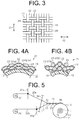
FIG. 3 is an enlarged view showing a fiber reinforcement base material. -
FIG. 4A is an enlarged cross-sectional view showing the fiber reinforcement base material that covers a body portion. -
FIG. 4B is an enlarged cross-sectional view showing the fiber reinforcement base material that covers a dome-shaped portion. -
FIG. 5 is a diagram schematically showing a method of producing the fiber structure woven with a loom. -
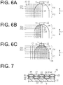
FIG. 6A is a diagram schematically showing a state after weft yarns are inserted. -
FIG. 6B is a diagram schematically showing a state after the weft yarns are beaten with a reed. -
FIG. 6C is a diagram schematically showing a state in which the fiber reinforcement base material is wound around a liner. -
FIG. 7 is a partial cross-sectional view showing a high-pressure tank of another example. - A fiber structure, a pressure container, and a method of producing the fiber structure will now be described with reference to an embodiment that embodies the fiber structure used in a high-pressure tank, the high-pressure tank, and a method of producing the fiber structure, shown in
FIGs. 1 through 6 . - As shown in
FIG. 1 , a high-pressure tank 10 serving as a pressure container is formed of afiber structure 21 impregnated with a matrix resin Ma. Thefiber structure 21 includes an elongated hollow-shapedliner 12, and a fiberreinforcement base material 19 that externally covers theliner 12. Theliner 12 of the high-pressure tank 10 is reinforced with a fiber-reinforcedcomposite layer 11 formed of the fiberreinforcement base material 19 impregnated with the matrix resin Ma. This secures a pressure resistance (a mechanical strength) of the high-pressure tank 10. - The
liner 12 is made of resin, and has an elongated hollow shape. A direction in which a center axis L of theliner 12 extends is referred to as an axial direction. Theliner 12 includes acylindrical body portion 13. A center axis of thebody portion 13 coincides with the center axis L of theliner 12. Theliner 12 includes a dome-shapedportion 14 at each of both ends of thebody portion 13 in an axial direction Y. An axial direction of each of the dome-shapedportions 14 coincides with the axial direction of theliner 12. Theliner 12 includes amouthpiece 15 that outwardly protrudes from each of the dome-shapedportions 14 in the axial direction Y. Themouthpieces 15 are made of metal (e.g. stainless steel). Each of themouthpieces 15 includes ahole portion 16 that communicates with a space in theliner 12. Avalve 17 is fitted into thehole portion 16 of one of themouthpieces 15 at one end of theliner 12 in the axial direction Y, and ascrew 18 is screwed into thehole portion 16 of the other of themouthpieces 15 at the other end of theliner 12 in the axial direction Y - The fiber
reinforcement base material 19 uses a carbon fiber as a reinforcement fiber according to the present embodiment. The reinforcement fiber is not limited to the carbon fiber, but other reinforcement fibers that are generally said to have high elasticity and high strength may be used, such as glass fibers, silicon-carbide base ceramic fibers, aramid fibers, and ultra-high molecular weight polyethylene fibers. - As shown in
FIG. 2 or3 , the fiberreinforcement base material 19 includes stacked layers of afabric 24 that is woven with a plain weave out of a plurality ofwarp yarns 22 corresponding to first yarns and a plurality ofweft yarns 23 corresponding to second yarns. Each of thewarp yarns 22 and each of theweft yarns 23 are arranged orthogonal to each other. The plurality ofwarp yarns 22 are arranged in thebody portion 13 and the dome-shapedportions 14 in a state where thewarp yarns 22 are parallel to one another, along the axial direction Y of theliner 12. A direction X1 in which a yarn main axis of thewarp yarns 22 proceeds ahead in thebody portion 13 and the dome-shapedportions 14 is a circumferential direction Z of theliner 12. The direction X1 of the yarn main axis of thewarp yarns 22 is orthogonal to a radial direction of theliner 12. - The plurality of
weft yarns 23 are arranged parallel to one another, along the circumferential direction Z of theliner 12. A portion of each of theweft yarns 23 that proceeds ahead in the axial direction of theliner 12 along the outer peripheral surface of thebody portion 13 is a body-portion weft yarn 23a. A portion of each of theweft yarns 23 that proceeds in the axial direction of theliner 12 along each of the outer peripheral surfaces of each of the dome-shapedportions 14 is a dome-portion weft yarn 23b. Each end of the body-portion weft yarn 23a is continuous with each of the dome-portion weft yarns 23b in the axial direction of theliner 12. As to theweft yarns 23, a direction X2 in which a yarn main axis of each of the dome-portion weft yarns 23b proceeds is the axial direction of theliner 12, curving along the each of the curved surfaces of each of the dome-shapedportions 14. Also as to theweft yarns 23, the direction X2 in which a yarn main axis of each of the body-portion weft yarns 23a proceeds is the axial direction of thebody portion 13 of theliner 12. - Each of the
warp yarns 22 and each of theweft yarns 23 are arranged orthogonal to each other. By making the direction X1 in which the yarn main axis of thewarp yarns 22 proceeds coincide with the circumferential direction of theliner 12, theliner 12 is reinforced in the radial direction. By making the direction X2 in which the yarn main axis of theweft yarns 23 proceeds coincide with the axial direction of theliner 12, theliner 12 is reinforced in the axial direction. - As shown in
FIG. 4A , the shape, the thickness, and the width of theweft yarns 23 of thebody portion 13 are flat, thin, and wide. As shown inFIG. 4B , the thickness and the width of theweft yarns 23 of the dome-shapedportions 14 are thicker and narrower than those of the body-portion weft yarn 23a, and become thicker and narrower even further as the diameter of the dome-shapedportion 14 decreases in a direction from thebody portion 13 toward themouthpiece 15. On the other hand, the thickness and the width of thewarp yarns 22 are the same in thebody portion 13 and in the dome-shapedportions 14. In thefiber structure 21, the number of theweft yarns 23 in the circumferential direction of theliner 12 is the same in thebody portion 13 and the dome-shapedportions 14. - A method of producing a high-
pressure tank 10 will now be described. - In producing the high-
pressure tank 10, the wovenfabric 24 is wound around theliner 12 while thewarp yarns 22 and theweft yarns 23 are woven with the plain weave. - As shown in
FIG. 5 , thefabric 24 is woven with, for example, a plain-weave loom that includes twoheddle frames warp yarns 22a andwarp yarns 22b of thewarp yarns 22 separated upper and lower. The plain-weave loom includes awarp beam 32 that supplies thewarp yarns 22a, one of thewarp yarns warp beam 33 that supplies thewarp yarns 22b, the other of thewarp yarns warp yarns 22a sent out from thewarp beam 32, one of the warp beams 32 and 33, is raised and lowered with theheddle frame 31a, one of the heddle frames 31a and 31b. Thewarp yarns 22b sent out from thewarp beam 33, the other of the warp beams 32 and 33, is raised and lowered with theheddle frame 31b, the other of the heddle frames 31a and 31b. Eyes of the heddle frames 31a and 31b are indicated with black-filled circles inFIG. 5 . Areed 34 is interposed between the two heddle frames of 31a and 31b and a cloth fell 35. Each of theweft yarns 23 is to be inserted in the shed between thewarp yarns warp yarns liner 12 is rotatably supported. Theliner 12 rotates around the center axis L. - In weaving the fiber
reinforcement base material 19 with the plain-weave loom described above, the ends of a plurality ofwarp yarns 22a and a plurality ofwarp yarns 22b that are drawn out of the warp beams 32 and 33 respectively are fixed to the outer peripheral surface of theliner 12 using a fixingmember 36 made of, for example, an adhesive tape, as shown inFIG. 6A . Thewarp yarns liner 12 in thebody portion 13 and the dome-shapedportions 14. - By alternately shifting to raise and lower the heddle frames 31a and 31b without rotating the
liner 12, theheddle frame 31a, the one of the heddle frames, and theheddle frame 31b, the other of the heddle frames, are shifted in the directions opposite to each other. Then, each of theweft yarns 23 is inserted into a warp shed 37 formed between thewarp yarns warp yarns weft yarns 23 have a flat shape after inserted. - Each of the
weft yarns 23 is inserted and beaten with thereed 34. Then, the heddle frames 31a and 31b are shifted in the directions opposite to each other so that the shedding state is changed. Subsequently, the next weft insertion is performed. These series of actions described above are repeated so that part of thefabric 24 is woven with the plain weave out of thewarp yarns 22 and theweft yarns 23 and the part of thefabric 24 is integrated with theliner 12 into a single piece. - As shown in
FIG. 6B , theweft yarns 23 is sent into the fixingmember 36 by being beaten with thereed 34. Thereed 34 is a member linearly extends in the axial direction of theliner 12. Since the diameter of the dome-shapedportions 14 is smaller than the diameter of thebody portion 13, theweft yarns 23 arranged in the dome-shapedportions 14 are pressed further than the portion of theweft yarns 23 arranged in thebody portion 13 when beaten with thereed 34, which causes theweft yarns 23 in the dome-shapedportions 14 to be deformed thicker. The resultant deformation in theweft yarns 23 in the dome-shapedportions 14 allows theweft yarns 23 to be arranged parallel to one another, along the circumferential direction of theliner 12, even in the state where thebody portion 13 has a different diameter from that of the dome-shapedportions 14. - Subsequently, as shown in
FIG. 6C , theliner 12 is rotated around the center axis L so that thefabric 24 is wound around theliner 12 while thefabric 24 continues to be woven in a like manner as described above. As a result, thefabric 24 is wound around theliner 12 entirely covering the dome-shapedportions 14 and thebody portion 13. By winding the predetermined number of the layers of thefabric 24 around theliner 12, thefiber structure 21 that includes the fiberreinforcement base material 19 on the outer peripheral surface of theliner 12 is produced. - In the
fiber structure 21 configured as described above, the fiber-reinforcedcomposite layer 11 is formed of the fiberreinforcement base material 19 with the matrix resin Ma impregnated thereinto and hardened, and then, the high-pressure tank 10 is produced with theliner 12 externally covered with the fiber-reinforcedcomposite layer 11. For impregnating and hardening the matrix resin Ma, the resin transfer molding (RTM) method, for example, is used. - The operation of a high-
pressure tank 10 will now be described. - The high-
pressure tank 10 is used, for example, as a hydrogen-supply source for fuel cells of a fuel cell vehicle. The high-pressure tank 10 is used in a state where a pipe (not shown) is connected to thevalve 17. Hydrogen gas is filled into the high-pressure tank 10 through the pipe for filling the hydrogen gas. In the high-pressure tank 10, the hydrogen gas that may have a pressure as high as several tens of MPa, for example, is filled. - When the hydrogen gas is filled into the high-
pressure tank 10, the pressure in the high-pressure tank 10 increases so that theliner 12 is pressed from the inside. Great forces are exerted on theliner 12 in the axial direction Y and the radial direction, by which an internal pressure stress is generated. According to the present embodiment, theliner 12 is reinforced in the axial direction by theweft yarns 23 and is reinforced in the radial direction by thewarp yarns 22, which suppresses deformation in the high-pressure tank 10. - The above-described embodiment has the following advantages.
- (1) In the
fiber structure 21 that forms the high-pressure tank 10, the direction X2 in which the yarn main axis of theweft yarns 23 proceeds coincides with the axial direction Y of thebody portion 13 and the dome-shapedportions 14. Theweft yarns 23 thereby reinforce theliner 12 in the axial direction. - (2) The direction X2 in which the yarn main axis of the
weft yarns 23 proceeds curves along the curved surfaces of the dome-shapedportions 14 of theliner 12 toward the axial direction Y in the dome-shapedportion 14. In this state, theweft yarns 23 are not angled relative to the axial direction Y Even the dome-shapedportion 14 is thereby reinforced in the axial direction Y - (3) The
weft yarn 23 that is just inserted is beaten with thereed 34 to be sent to theweft yarn 23 that has been previously inserted, which allows theweft yarns 23 to be arranged closely one another along the circumferential direction of theliner 12. In the dome-shapedportions 14 that have smaller diameters than thebody portion 13 has, theweft yarns 23 are beaten and pressed by thereed 34, which allows theweft yarns 23 to be arranged parallel to one another even in the dome-shapedportions 14 and which also prevents from generating wrinkles. The density of theweft yarns 23 is thereby the same in thebody portion 13 and the dome-shapedportions 14, and wrinkles are prevented from being generated in thefiber structure 21 even on the curved surfaces of the dome-shapedportions 14. - (4) An example of a conventional method of producing the
fiber structure 21 that includes the fiberreinforcement base material 19 externally covering theliner 12 may be filament winding. In this method, productivity is low because yarns are wound around theliner 12 individually one by one. On the other hand, the productivity in producing thefiber structure 21 according to the present embodiment is enhanced as compared to the filament winding, because thefabric 24 is wound around theliner 12 while thefabric 24 is woven out of thewarp yarns 22 and theweft yarns 23. - Another example of a conventional method of producing the
fiber structure 21 that includes the fiberreinforcement base material 19 on the outer peripheral surface of theliner 12 may be braiding, in which a fabric is woven into a tubular shape to fit to the shape of theliner 12 by braiding, cut open into a flat shape, and then wound around theliner 12. In contrast to this conventional method, the fiberreinforcement base material 19 according to the present embodiment is wound around theliner 12 while the fiberreinforcement base material 19 is woven out of thewarp yarns 22 and theweft yarns 23, which does not require an individual process to weave the fabric, a process to cut open the fabric, and a process to paste the fabric to the liner. Productivity is thereby enhanced as compared to the braiding. Theliner 12 according to the present embodiment is reinforced in the axial direction because the direction X2 in which the yarn main axis of theweft yarns 23 proceeds is the axial direction of theliner 12. - The following modifications may be made to the embodiment described above.
- As shown in
FIG. 7 , a fiberreinforcement base material 40 may be a multi-layered fabric woven with multilayer weaving. The fiberreinforcement base material 40 includes warp layers 41 and 42 in whichwarp yarns 22 are arranged parallel to one another, aweft layer 43 in whichweft yarns 23 are arranged parallel to one another, and abinder yarn 45 that binds the warp layers 41 and 42 and theweft layer 43 in the stacking direction. Thebinder yarn 45 proceeds around the outer surface of one of thewarp yarns 22 that form thewarp layer 41, proceeds through thewarp layer 41 in the stacking direction, and then proceeds around the outer surface of another of thewarp yarns 22 that form thewarp layer 42. - In a
fiber structure 46 including the fiberreinforcement base material 40 described above, a matrix resin (not shown) is impregnated along thebinder yarn 45 into the fiberreinforcement base material 40 through the stacking direction of the fiberreinforcement base material 40. Thefiber structure 46 is thereby reinforced also in the stacking direction. The number of the warp layers and the weft layers may be appropriately changed. - In the embodiment described above, the fiber
reinforcement base material 19 includes the stacked layers of thefabric 24 that is woven with the plain weave. The scope of the present invention is not limited to the embodiment described above. For example, the fiberreinforcement base material 19 may include the stacked layers of a fabric that is woven with a satin weave or a twill weave out of a plurality of thewarp yarns 22 corresponding to the first yarns and a plurality of theweft yarns 23 corresponding to the second yarns. - In the embodiment described above, the
warp yarn 22 is referred to as the first yarn, and theweft yarn 23 is referred to as the second yarn. However, theweft yarn 23 may be referred to as the first yarn and thewarp yarn 22 may be referred to as the second yarn. - The
liner 12 may have a shape in which one end of thebody portion 13 in the axial direction Y is continuous with the dome-shapedportion 14 and the other end of thebody portion 13 in the axial direction Y is continuous with a flat bottom surface. In this case, themouthpiece 15 is provided only to the one end of theline 12 in the axial direction Y where the dome-shapedportion 14 is disposed. - The
liner 12 may be made of aluminum alloy, instead of being entirely made of aluminum. Themouthpiece 15 may be made of metal other than stainless steel. - The
body portion 13 and the dome-shapedportions 14 of theliner 12 may be welded into a single piece, instead of being separated. - The high-
pressure tank 10 in the embodiment described above is used as a hydrogen-supply source for fuel cells to be mounted on a fuel cell vehicle. The scope of the present invention is not limited to the embodiment. For example, the high-pressure tank 10 may be used as a hydrogen-supply source to power a hydrogen engine or may be used for a heat pump. Alternatively, the high-pressure tank 10 may be used as a hydrogen-supply source for fuel cells for household use. - The high-
pressure tank 10 in the embodiment described above is used to store hydrogen as the pressure container. The scope of the present invention is not limited to the embodiment. For example, the pressure container may be used to store other types of gases such as nitrogen and compressed natural gas. -
- L
- center axis
- Y
- axial direction
- Z
- circumferential direction
- Ma
- matrix resin
- X1, X2
- direction of yarn main axis
- 10
- high-pressure tank as pressure container
- 12
- liner
- 13
- body portion
- 14
- dome-shaped portion
- 15
- mouthpiece
- 19, 40
- fiber reinforcement base material
- 21, 46
- fiber structure
- 22
- warp yarn as first yarn
- 23
- weft yarn as second yarn
- 24
- fabric
- 41, 42
- warp layer as first yarn layer
- 43
- weft layer as second yarn layer
- 45
- binder yarn
Claims (4)
- A fiber structure, comprising:a liner including:a body portion having a cylindrical shape;a dome-shaped portion being continuous with at least one end of the body portion in an axial direction thereof; anda mouthpiece having a shape protruding from the dome-shaped portion in the axial direction of the body portion; anda fiber reinforcement base material formed of a fabric, the fiber reinforcement base material externally covering the body portion and the dome-shaped portion of the liner, whereinthe fiber reinforcement base material includes:first yarns arranged in such a way that a direction in which a yarn main axis of each of the first yarns in the body portion and the dome-shaped portion proceeds is a circumferential direction of the liner; andsecond yarns forming the fabric with the first yarns, the second yarns being arranged in such a way that a direction in which a yarn main axis of each of the second yarns in the body portion proceeds is the axial direction of the body portion and that a direction in which a yarn main axis of a portion of each of the second yarns arranged in the dome-shaped portion proceeds is an axial direction of the dome-shaped portion.
- The fiber structure according to claim 1, wherein the fabric is a multi-layered fabric comprising:a first yarn layer in which the first yarns are arranged;a second yarn layer in which the second yarns are arranged; anda binder yarn binding the first yarn layer and the second yarn layer.
- A pressure container, comprising:
a fiber structure impregnated with a matrix resin, the fiber structure including:a fiber reinforcement base material formed of a fabric, the fiber reinforcement base material externally covering a liner, whereinthe fiber structure is the fiber structure according to claim 1 or 2. - A method of producing a fiber structure, the fiber structure comprising:a liner including:a body portion having a cylindrical shape;a dome-shaped portion being continuous with at least one end of the body portion in an axial direction thereof; anda mouthpiece having a shape protruding from the dome-shaped portion in the axial direction of the body portion; anda fiber reinforcement base material formed of a fabric, the fiber reinforcement base material externally covering the body portion and the dome-shaped portion of the liner;warp yarns arranged in such a way that a direction in which a yarn main axis of each of the warp yarns in the body portion and the dome-shaped portion proceeds is a circumferential direction of the liner; andweft yarns forming the fabric with the warp yarns, wherein the method of producing the fiber structure comprising:keeping a tension on the warp yarns in a state where the warp yarns are arranged along the axial direction of the body portion and the dome-shaped portion of the liner;inserting each of the weft yarns into a shed formed between the warp yarns adjacent to each other in the axial direction of the liner;pressing the inserted weft yarn toward the liner by beating with a reed to weave the fabric out of the warp yarns and the weft yarns; andwinding the woven fabric around the liner by rotating the liner around a center axis of the liner.
Applications Claiming Priority (2)
| Application Number | Priority Date | Filing Date | Title |
|---|---|---|---|
| JP2017083504A JP6729472B2 (en) | 2017-04-20 | 2017-04-20 | Fiber structure, pressure vessel, and method for manufacturing fiber structure |
| PCT/JP2018/014631 WO2018193868A1 (en) | 2017-04-20 | 2018-04-05 | Fiber structure, pressure container, and method for manufacturing fiber structure |
Publications (3)
| Publication Number | Publication Date |
|---|---|
| EP3614034A1 true EP3614034A1 (en) | 2020-02-26 |
| EP3614034A4 EP3614034A4 (en) | 2020-04-15 |
| EP3614034B1 EP3614034B1 (en) | 2025-08-06 |
Family
ID=63855879
Family Applications (1)
| Application Number | Title | Priority Date | Filing Date |
|---|---|---|---|
| EP18787230.4A Active EP3614034B1 (en) | 2017-04-20 | 2018-04-05 | Fiber structure, pressure container, and method for manufacturing fiber structure |
Country Status (5)
| Country | Link |
|---|---|
| US (1) | US11092287B2 (en) |
| EP (1) | EP3614034B1 (en) |
| JP (1) | JP6729472B2 (en) |
| CN (1) | CN110520667B (en) |
| WO (1) | WO2018193868A1 (en) |
Cited By (1)
| Publication number | Priority date | Publication date | Assignee | Title |
|---|---|---|---|---|
| WO2022058182A1 (en) * | 2020-09-21 | 2022-03-24 | Bayerische Motoren Werke Aktiengesellschaft | Pressure container and pressure container system |
Families Citing this family (17)
| Publication number | Priority date | Publication date | Assignee | Title |
|---|---|---|---|---|
| EP3434962B1 (en) * | 2017-07-26 | 2022-02-23 | Nproxx B.V. | Fibre-reinforced pressure vessel |
| WO2020026811A1 (en) * | 2018-07-31 | 2020-02-06 | 株式会社豊田自動織機 | Pressure vessel and pressure-vessel manufacturing method |
| JP2020158937A (en) * | 2019-03-28 | 2020-10-01 | 株式会社豊田自動織機 | Reinforcing fiber structure and manufacturing method of reinforcing fiber structure |
| JP7111049B2 (en) * | 2019-04-10 | 2022-08-02 | 株式会社豊田自動織機 | Textile structures and pressure vessels |
| US20200347992A1 (en) | 2019-05-02 | 2020-11-05 | Agility Fuel Systems Llc | Polymeric liner based gas cylinder with reduced permeability |
| JP7131523B2 (en) * | 2019-10-16 | 2022-09-06 | トヨタ自動車株式会社 | module |
| JP2021091106A (en) * | 2019-12-06 | 2021-06-17 | 株式会社豊田自動織機 | Fiber preform for pressure vessel |
| CN114636093B (en) * | 2020-12-15 | 2023-09-01 | 宇通客车股份有限公司 | Carbon fiber wound gas cylinder and preparation method thereof |
| WO2022138996A1 (en) * | 2020-12-21 | 2022-06-30 | 일진복합소재 주식회사 | Hydrogen storage tank having non-fixed shape and method for producing same |
| US12358365B1 (en) | 2021-05-07 | 2025-07-15 | Agility Fuel Systems Llc | Vehicles having composite interwoven gas containment assemblies |
| EP4291818A4 (en) * | 2021-05-07 | 2025-01-08 | Agility Fuel Systems LLC | COMPOSITE INTERLACED GAS CONTAINMENT ASSEMBLIES |
| JP7687061B2 (en) * | 2021-06-04 | 2025-06-03 | 株式会社豊田自動織機 | Fiber Structure |
| JP7687274B2 (en) | 2022-05-19 | 2025-06-03 | トヨタ自動車株式会社 | Gas tank and manufacturing method thereof |
| JP7652135B2 (en) * | 2022-05-19 | 2025-03-27 | トヨタ自動車株式会社 | Gas tank and manufacturing method thereof |
| FR3137433B1 (en) * | 2022-06-29 | 2024-08-09 | Mattei Jean Pierre | Composite tanks with braided shell and corresponding manufacturing processes |
| CN116146374A (en) * | 2023-01-31 | 2023-05-23 | 南京航空航天大学 | A shell of multi-axial braided composite material |
| CN119485830B (en) * | 2025-01-16 | 2025-04-18 | 上海德赟电热材料科技有限公司 | Layered fabric heating core, heating core manufacturing equipment and control system thereof |
Family Cites Families (31)
| Publication number | Priority date | Publication date | Assignee | Title |
|---|---|---|---|---|
| US2858992A (en) * | 1955-03-04 | 1958-11-04 | Specialties Dev Corp | Winding machine |
| US3047191A (en) * | 1957-11-26 | 1962-07-31 | Hercules Powder Co Ltd | Filament wound vessels and methods for forming same |
| US3276936A (en) * | 1960-06-15 | 1966-10-04 | Us Rubber Co | Filament winding apparatus |
| US3843010A (en) * | 1971-10-13 | 1974-10-22 | Brunswick Corp | Metal lined pressure vessel |
| US3969812A (en) * | 1974-04-19 | 1976-07-20 | Martin Marietta Corporation | Method of manufacturing an overwrapped pressure vessel |
| US4410385A (en) * | 1981-01-28 | 1983-10-18 | General Electric Company | Method of making a composite article |
| US4407885A (en) * | 1981-01-28 | 1983-10-04 | General Electric Company | Composite article |
| JPH02200840A (en) * | 1989-01-23 | 1990-08-09 | Ashimori Ind Co Ltd | Disklike woven fabric and production thereof |
| JP2839383B2 (en) * | 1991-03-25 | 1998-12-16 | 芦森工業株式会社 | Tubular multilayer fabric and method for producing the same |
| CN2469299Y (en) * | 2001-04-04 | 2002-01-02 | 中国科学院金属研究所 | Cross winded compound high pressure gas bottle |
| US7100262B2 (en) * | 2003-07-08 | 2006-09-05 | Polymer & Steel Technologies Holding Company Llc | Method of forming filament-reinforced composite thermoplastic pressure vessel fitting assembly |
| JPWO2005022026A1 (en) * | 2003-08-28 | 2006-10-26 | 三菱レイヨン株式会社 | High performance pressure vessel and carbon fiber for pressure vessel |
| EP1520683B1 (en) * | 2003-10-01 | 2008-02-27 | Fuji Jukogyo Kabushiki Kaisha | Pressure container manufacturing method |
| JP4431469B2 (en) * | 2004-09-14 | 2010-03-17 | 富士重工業株式会社 | Pressure vessel manufacturing method and fiber bundle winding device |
| JP2006132746A (en) * | 2004-11-09 | 2006-05-25 | Toyota Industries Corp | Pressure vessel, hydrogen storage tank, and pressure vessel manufacturing method |
| US8858857B2 (en) | 2007-03-12 | 2014-10-14 | Geoffrey Michael Wood | Process for the rapid fabrication of composite gas cylinders and related shapes |
| US8038029B2 (en) * | 2008-06-13 | 2011-10-18 | GM Global Technology Operations LLC | Activation of a pressure relief device |
| US8074826B2 (en) * | 2008-06-24 | 2011-12-13 | Composite Technology Development, Inc. | Damage and leakage barrier in all-composite pressure vessels and storage tanks |
| JP5238577B2 (en) * | 2009-03-31 | 2013-07-17 | Jx日鉱日石エネルギー株式会社 | Composite container and method for manufacturing composite container |
| US9316359B2 (en) * | 2009-04-10 | 2016-04-19 | Toyota Jidosha Kabushiki Kaisha | Tank and manufacturing method thereof |
| US8602250B2 (en) * | 2009-05-04 | 2013-12-10 | GM Global Technology Operations LLC | Storage vessel and method of forming |
| JP2010265931A (en) * | 2009-05-12 | 2010-11-25 | Toyota Motor Corp | Tank and manufacturing method thereof |
| WO2013035518A1 (en) * | 2011-09-08 | 2013-03-14 | 株式会社 豊田自動織機 | Woven fabric base material and fiber-reinforced composite material |
| EP2788652B1 (en) * | 2011-12-05 | 2017-11-01 | Blue Wave Co S.A. | Method of fabricating a pressure vessel using a variable viscosity prepolymer formulation and pressure vessel obtained thereby |
| JP5928069B2 (en) * | 2012-03-28 | 2016-06-01 | トヨタ紡織株式会社 | fabric |
| JP2015030959A (en) * | 2013-08-07 | 2015-02-16 | 株式会社豊田自動織機 | Woven fabric, and fiber bundle and fiber-reinforced composite material for composing woven fabric |
| US9874311B2 (en) * | 2014-06-13 | 2018-01-23 | GM Global Technology Operations LLC | Composite pressure vessel having a third generation advanced high strength steel (AHSS) filament reinforcement |
| CN107002873A (en) * | 2014-11-28 | 2017-08-01 | 三菱瓦斯化学株式会社 | The manufacture method of pressure vessel, pad and pressure vessel |
| JP2017115938A (en) * | 2015-12-22 | 2017-06-29 | ニッタ株式会社 | High pressure vessel and method for manufacturing high pressure vessel |
| EP3267091A1 (en) * | 2016-07-04 | 2018-01-10 | Plastic Omnium Advanced Innovation and Research | Pressure vessel with a tape-based reinforcement structure |
| US10724684B2 (en) * | 2016-09-20 | 2020-07-28 | Amtrol Licensing Inc. | Fiberwound tanks |
-
2017
- 2017-04-20 JP JP2017083504A patent/JP6729472B2/en active Active
-
2018
- 2018-04-05 EP EP18787230.4A patent/EP3614034B1/en active Active
- 2018-04-05 WO PCT/JP2018/014631 patent/WO2018193868A1/en not_active Ceased
- 2018-04-05 CN CN201880025221.0A patent/CN110520667B/en active Active
- 2018-04-20 US US16/606,634 patent/US11092287B2/en active Active
Cited By (1)
| Publication number | Priority date | Publication date | Assignee | Title |
|---|---|---|---|---|
| WO2022058182A1 (en) * | 2020-09-21 | 2022-03-24 | Bayerische Motoren Werke Aktiengesellschaft | Pressure container and pressure container system |
Also Published As
| Publication number | Publication date |
|---|---|
| JP6729472B2 (en) | 2020-07-22 |
| EP3614034B1 (en) | 2025-08-06 |
| US20200072415A1 (en) | 2020-03-05 |
| CN110520667B (en) | 2021-07-20 |
| JP2018179248A (en) | 2018-11-15 |
| US11092287B2 (en) | 2021-08-17 |
| CN110520667A (en) | 2019-11-29 |
| WO2018193868A1 (en) | 2018-10-25 |
| EP3614034A4 (en) | 2020-04-15 |
Similar Documents
| Publication | Publication Date | Title |
|---|---|---|
| US11092287B2 (en) | Fiber structure, pressure container, and method of producing fiber structure | |
| US11549643B2 (en) | Pressure vessel and pressure-vessel manufacturing method | |
| CN107850259B (en) | Pressure Vessels with Reinforced Heads | |
| WO2019171889A1 (en) | Fiber structure and pressure container | |
| JP7111049B2 (en) | Textile structures and pressure vessels | |
| EP2493677B1 (en) | Fiber preform, fiber reinforced composite, and method of making thereof | |
| US10190240B2 (en) | Woven preform, composite, and method of making thereof | |
| JP6975895B2 (en) | Manufacturing method of FRP tubular body and FRP tubular body | |
| JP7040347B2 (en) | Pressure vessel and manufacturing method of pressure vessel | |
| EP4284624B1 (en) | High pressure composite pressure vessel method of manufacture and product | |
| JP7040346B2 (en) | Pressure vessel and manufacturing method of pressure vessel | |
| JP7687061B2 (en) | Fiber Structure | |
| JP2021091976A (en) | Fiber structure | |
| US20250205992A1 (en) | Fiber structure | |
| CN113639187B (en) | Three-dimensional woven high-performance hydrogen storage pressure vessel with reinforced fiber continuous filament structure | |
| JP2021091977A (en) | Fiber structure | |
| WO2020100797A1 (en) | Spun yarn | |
| CN116249855A (en) | Pressure Vessels and Pressure Vessel Systems | |
| KR20240095931A (en) | Hydrogen pressure vessel and method for manufacturing the same |
Legal Events
| Date | Code | Title | Description |
|---|---|---|---|
| STAA | Information on the status of an ep patent application or granted ep patent |
Free format text: STATUS: THE INTERNATIONAL PUBLICATION HAS BEEN MADE |
|
| PUAI | Public reference made under article 153(3) epc to a published international application that has entered the european phase |
Free format text: ORIGINAL CODE: 0009012 |
|
| STAA | Information on the status of an ep patent application or granted ep patent |
Free format text: STATUS: REQUEST FOR EXAMINATION WAS MADE |
|
| 17P | Request for examination filed |
Effective date: 20190925 |
|
| AK | Designated contracting states |
Kind code of ref document: A1 Designated state(s): AL AT BE BG CH CY CZ DE DK EE ES FI FR GB GR HR HU IE IS IT LI LT LU LV MC MK MT NL NO PL PT RO RS SE SI SK SM TR |
|
| AX | Request for extension of the european patent |
Extension state: BA ME |
|
| A4 | Supplementary search report drawn up and despatched |
Effective date: 20200318 |
|
| RIC1 | Information provided on ipc code assigned before grant |
Ipc: F16J 12/00 20060101ALI20200312BHEP Ipc: F17C 1/06 20060101AFI20200312BHEP |
|
| DAV | Request for validation of the european patent (deleted) | ||
| DAX | Request for extension of the european patent (deleted) | ||
| STAA | Information on the status of an ep patent application or granted ep patent |
Free format text: STATUS: EXAMINATION IS IN PROGRESS |
|
| 17Q | First examination report despatched |
Effective date: 20220504 |
|
| P01 | Opt-out of the competence of the unified patent court (upc) registered |
Effective date: 20230519 |
|
| GRAP | Despatch of communication of intention to grant a patent |
Free format text: ORIGINAL CODE: EPIDOSNIGR1 |
|
| STAA | Information on the status of an ep patent application or granted ep patent |
Free format text: STATUS: GRANT OF PATENT IS INTENDED |
|
| INTG | Intention to grant announced |
Effective date: 20250304 |
|
| GRAS | Grant fee paid |
Free format text: ORIGINAL CODE: EPIDOSNIGR3 |
|
| GRAA | (expected) grant |
Free format text: ORIGINAL CODE: 0009210 |
|
| STAA | Information on the status of an ep patent application or granted ep patent |
Free format text: STATUS: THE PATENT HAS BEEN GRANTED |
|
| AK | Designated contracting states |
Kind code of ref document: B1 Designated state(s): AL AT BE BG CH CY CZ DE DK EE ES FI FR GB GR HR HU IE IS IT LI LT LU LV MC MK MT NL NO PL PT RO RS SE SI SK SM TR |
|
| REG | Reference to a national code |
Ref country code: GB Ref legal event code: FG4D |
|
| REG | Reference to a national code |
Ref country code: CH Ref legal event code: EP |
|
| REG | Reference to a national code |
Ref country code: DE Ref legal event code: R096 Ref document number: 602018084341 Country of ref document: DE |
|
| REG | Reference to a national code |
Ref country code: IE Ref legal event code: FG4D |
|
| REG | Reference to a national code |
Ref country code: NL Ref legal event code: MP Effective date: 20250806 |
|
| PG25 | Lapsed in a contracting state [announced via postgrant information from national office to epo] |
Ref country code: IS Free format text: LAPSE BECAUSE OF FAILURE TO SUBMIT A TRANSLATION OF THE DESCRIPTION OR TO PAY THE FEE WITHIN THE PRESCRIBED TIME-LIMIT Effective date: 20251206 |
|
| PG25 | Lapsed in a contracting state [announced via postgrant information from national office to epo] |
Ref country code: NO Free format text: LAPSE BECAUSE OF FAILURE TO SUBMIT A TRANSLATION OF THE DESCRIPTION OR TO PAY THE FEE WITHIN THE PRESCRIBED TIME-LIMIT Effective date: 20251106 |
|
| REG | Reference to a national code |
Ref country code: LT Ref legal event code: MG9D |
|
| PG25 | Lapsed in a contracting state [announced via postgrant information from national office to epo] |
Ref country code: PT Free format text: LAPSE BECAUSE OF FAILURE TO SUBMIT A TRANSLATION OF THE DESCRIPTION OR TO PAY THE FEE WITHIN THE PRESCRIBED TIME-LIMIT Effective date: 20251209 |
|
| PG25 | Lapsed in a contracting state [announced via postgrant information from national office to epo] |
Ref country code: FI Free format text: LAPSE BECAUSE OF FAILURE TO SUBMIT A TRANSLATION OF THE DESCRIPTION OR TO PAY THE FEE WITHIN THE PRESCRIBED TIME-LIMIT Effective date: 20250806 |
|
| PG25 | Lapsed in a contracting state [announced via postgrant information from national office to epo] |
Ref country code: HR Free format text: LAPSE BECAUSE OF FAILURE TO SUBMIT A TRANSLATION OF THE DESCRIPTION OR TO PAY THE FEE WITHIN THE PRESCRIBED TIME-LIMIT Effective date: 20250806 Ref country code: NL Free format text: LAPSE BECAUSE OF FAILURE TO SUBMIT A TRANSLATION OF THE DESCRIPTION OR TO PAY THE FEE WITHIN THE PRESCRIBED TIME-LIMIT Effective date: 20250806 |
|
| PG25 | Lapsed in a contracting state [announced via postgrant information from national office to epo] |
Ref country code: GR Free format text: LAPSE BECAUSE OF FAILURE TO SUBMIT A TRANSLATION OF THE DESCRIPTION OR TO PAY THE FEE WITHIN THE PRESCRIBED TIME-LIMIT Effective date: 20251107 |
|
| PG25 | Lapsed in a contracting state [announced via postgrant information from national office to epo] |
Ref country code: SE Free format text: LAPSE BECAUSE OF FAILURE TO SUBMIT A TRANSLATION OF THE DESCRIPTION OR TO PAY THE FEE WITHIN THE PRESCRIBED TIME-LIMIT Effective date: 20250806 |
|
| PG25 | Lapsed in a contracting state [announced via postgrant information from national office to epo] |
Ref country code: LV Free format text: LAPSE BECAUSE OF FAILURE TO SUBMIT A TRANSLATION OF THE DESCRIPTION OR TO PAY THE FEE WITHIN THE PRESCRIBED TIME-LIMIT Effective date: 20250806 |
|
| PG25 | Lapsed in a contracting state [announced via postgrant information from national office to epo] |
Ref country code: PL Free format text: LAPSE BECAUSE OF FAILURE TO SUBMIT A TRANSLATION OF THE DESCRIPTION OR TO PAY THE FEE WITHIN THE PRESCRIBED TIME-LIMIT Effective date: 20250806 Ref country code: BG Free format text: LAPSE BECAUSE OF FAILURE TO SUBMIT A TRANSLATION OF THE DESCRIPTION OR TO PAY THE FEE WITHIN THE PRESCRIBED TIME-LIMIT Effective date: 20250806 |
|
| PG25 | Lapsed in a contracting state [announced via postgrant information from national office to epo] |
Ref country code: RS Free format text: LAPSE BECAUSE OF FAILURE TO SUBMIT A TRANSLATION OF THE DESCRIPTION OR TO PAY THE FEE WITHIN THE PRESCRIBED TIME-LIMIT Effective date: 20251106 |
|
| PG25 | Lapsed in a contracting state [announced via postgrant information from national office to epo] |
Ref country code: ES Free format text: LAPSE BECAUSE OF FAILURE TO SUBMIT A TRANSLATION OF THE DESCRIPTION OR TO PAY THE FEE WITHIN THE PRESCRIBED TIME-LIMIT Effective date: 20250806 |
|
| REG | Reference to a national code |
Ref country code: AT Ref legal event code: MK05 Ref document number: 1822208 Country of ref document: AT Kind code of ref document: T Effective date: 20250806 |
|
| PG25 | Lapsed in a contracting state [announced via postgrant information from national office to epo] |
Ref country code: SM Free format text: LAPSE BECAUSE OF FAILURE TO SUBMIT A TRANSLATION OF THE DESCRIPTION OR TO PAY THE FEE WITHIN THE PRESCRIBED TIME-LIMIT Effective date: 20250806 |
|
| PG25 | Lapsed in a contracting state [announced via postgrant information from national office to epo] |
Ref country code: DK Free format text: LAPSE BECAUSE OF FAILURE TO SUBMIT A TRANSLATION OF THE DESCRIPTION OR TO PAY THE FEE WITHIN THE PRESCRIBED TIME-LIMIT Effective date: 20250806 |
|
| PG25 | Lapsed in a contracting state [announced via postgrant information from national office to epo] |
Ref country code: AT Free format text: LAPSE BECAUSE OF FAILURE TO SUBMIT A TRANSLATION OF THE DESCRIPTION OR TO PAY THE FEE WITHIN THE PRESCRIBED TIME-LIMIT Effective date: 20250806 |
|
| PG25 | Lapsed in a contracting state [announced via postgrant information from national office to epo] |
Ref country code: CZ Free format text: LAPSE BECAUSE OF FAILURE TO SUBMIT A TRANSLATION OF THE DESCRIPTION OR TO PAY THE FEE WITHIN THE PRESCRIBED TIME-LIMIT Effective date: 20250806 |
|
| PG25 | Lapsed in a contracting state [announced via postgrant information from national office to epo] |
Ref country code: EE Free format text: LAPSE BECAUSE OF FAILURE TO SUBMIT A TRANSLATION OF THE DESCRIPTION OR TO PAY THE FEE WITHIN THE PRESCRIBED TIME-LIMIT Effective date: 20250806 Ref country code: SK Free format text: LAPSE BECAUSE OF FAILURE TO SUBMIT A TRANSLATION OF THE DESCRIPTION OR TO PAY THE FEE WITHIN THE PRESCRIBED TIME-LIMIT Effective date: 20250806 |