EP3613910A1 - Building connector with thermal insulation - Google Patents
Building connector with thermal insulation Download PDFInfo
- Publication number
- EP3613910A1 EP3613910A1 EP18460050.0A EP18460050A EP3613910A1 EP 3613910 A1 EP3613910 A1 EP 3613910A1 EP 18460050 A EP18460050 A EP 18460050A EP 3613910 A1 EP3613910 A1 EP 3613910A1
- Authority
- EP
- European Patent Office
- Prior art keywords
- profile
- steel
- load bearing
- profiles
- bearing elements
- Prior art date
- Legal status (The legal status is an assumption and is not a legal conclusion. Google has not performed a legal analysis and makes no representation as to the accuracy of the status listed.)
- Granted
Links
Images



Classifications
-
- E—FIXED CONSTRUCTIONS
- E04—BUILDING
- E04B—GENERAL BUILDING CONSTRUCTIONS; WALLS, e.g. PARTITIONS; ROOFS; FLOORS; CEILINGS; INSULATION OR OTHER PROTECTION OF BUILDINGS
- E04B1/00—Constructions in general; Structures which are not restricted either to walls, e.g. partitions, or floors or ceilings or roofs
- E04B1/003—Balconies; Decks
- E04B1/0038—Anchoring devices specially adapted therefor with means for preventing cold bridging
Definitions
- This invention is related to a building connector with thermal insulation used to connect an external ferroconcrete element of a building, particularly provided as a balcony slab, with an internal ferroconcrete element of a building, for example with ferroconcrete ceiling, a ferroconcrete girder or a ferroconcrete ring beam of a masonry building.
- a range of building connector designs is known in the art, including solutions containing thermal insulation elements.
- a solution according to the international patent application WO 00/47834 discloses an embodiment of a device used to fix supporting panels onto a wall structure or onto a ceiling structure.
- the supporting device includes at least one connector, which is provided with a reinforcing part and numerous parts improving traction and pressure. These parts are running through the wall structure or through the ceiling structure, together with numerous parts improving traction and pressure, running through the supporting plate.
- the device according to the invention also includes an insulating body, connected with the connector.
- the reinforcing parts are connected within the highest strain area using connection points with the reinforcing profile, using thin-walled reinforcing profiles made of stainless steel.
- the reinforcing profiles are also preferably interconnected, in particular, they can be provided as a single element, and the insulating element is running only across the middle part of every reinforcing profile instead of connection points.
- the aforementioned device connecting supports with the wall structure or the ceiling structure includes at least one connector provided with a reinforcing part and numerous parts passing into the wall structure or into the ceiling structure and many reinforcing parts running within the supporting plate.
- the insulating body is connected with the connector.
- the reinforcing parts include a reinforcing profile provided as a C-shaped profile or as a H-shaped profile, with horizontal arms and a vertical shelf, and with thin-walled reinforcing profiles. These profiles are made of high quality stainless steel and are connected using connection points.
- the reinforcing profiles are also preferably interconnected.
- the daB element comprising the insulating body is located below the top row of connectors. Connections of every reinforcing profile with reinforcing bars are provided as welded joints.
- reinforcing bars are welded to arms of the C-shaped profiles and of the H-shaped profiles.
- a device according to this solution known in the art has the vertical part of the reinforcing profile preferably provided with elliptic depressions. At least one arm of the reinforcing profile is provided with at least one protrusion.
- the reinforcing profiles may also be U-shaped.
- each profile of this solution known in the art has two reinforcing bars attached to each of the arms, which can be provided as an U-shaped, open shackle, wherein the top arm of the shackle is welded to the top arm of the reinforcing profile, while the bottom arm of the shackle is welded to the bottom arm of the profile.
- the reinforcing profiles are connected at their ends using a least one U-shaped, external reinforcing support and at least one U-shaped, internal reinforcing support.
- the reinforcing bars are made of reinforcing steel.
- the surface of reinforcing bars is provided with ribbed walls.
- At least one reinforcing bar may be positioned at an angle.
- a device according to this solution is provided with at least two connecting bars which may be connected using at least one transverse connector and may be connected with a reinforcing basket.
- the insulating body may be made of several individual elements placed on reinforcing profiles or partially enclosing such profiles.
- the subject of the solution is a building element used to form connections between two parts of a buildings, thermally insulated from each other.
- This element includes a longitudinal part made of a thermally insulating material and is designed to be placed between building parts.
- This product includes bars penetrating the thermally insulated part.
- the elements are designed to be anchored within building parts being connected to each other.
- the goal of the product is to absorb stretching forces present between these elements of a single building.
- the goal of the product also includes development of solutions absorbing crushing and shearing forces present between the aforementioned building elements.
- the building element includes metal bars, and non-metallic bars made of thermally insulating material. In this solution, metal bars are designed to hold the connection together, while it loses the stretching force absorbed by the non-metallic bars.
- the building element used to connect two building parts to be thermally isolated from each other includes a longitudinal element made of thermally insulating material, designed to be placed between building parts and steel bars penetrating the thermally insulating element.
- the bars are configured for anchoring in building parts to be connected and for being connected with reinforcement of the connected building parts.
- the bars absorb stretching forces between the listed building elements, measures used to absorb crushing and shearing forces between building elements.
- the aforementioned metal and non-metallic bars are made of thermally insulating material.
- a non-metallic bar is placed on either side and close to each metal bar.
- the building element usually includes a group of three bars, a single, central, metal bar and two non-metallic bars absorbing crushing and shearing forces.
- the measures used to absorb crushing and shearing forces comprise supporting blocks in this case.
- Metal bars are made of steel in the case of this solution, while the composition of non-metallic bars is based on basalt.
- Another solution is also known, which uses pairs of C-shaped profiles penetrating a layer assembled using profiles made of a thermally insulating material.
- Each pair of the C-shaped profiles, the top and the bottom profile is connected on one side using two U-shaped reinforcing bars and two U-shaped reinforcing bars on the other side.
- Two parallel, U-shaped bars are welded to the first arm ends of every C-shaped profile, and two similar, parallel U-shaped bars are welded to the second arm ends of every C-shaped profile.
- two similar, parallel U-shaped bars are welded to the remaining U-shaped bar arms.
- the U-shaped bars thus welded to and on both sides of the C-shaped profiles provide bars extending these C-shaped profiles and welded to their arms.
- U-shaped bars connect the pair including the top and the bottom C-shaped profile within the end area of these C-shaped profiles.
- An identical connection using two more U-shaped bars is provided on the other side, in the second ends area of the same C-shaped profiles.
- a pair of C-shaped profiles is connected on each side using two U-shaped bars, wherein arms of these bars provide an extension of those C-shaped profiles.
- four bar arms on one side of the pair of C-shaped profile are intended for connection with reinforcement of an external building element, for example of a balcony slab, while four bar arms on the opposite side of the same pair of C-shaped profiles are intended for connection with reinforcement of an internal building element, for example, of a ceiling.
- Each pair of the C-shaped profiles with the bars, the top and the bottom C-shaped profile, is free of reinforcing bars in the middle part of its length.
- a range of such pairs of C-shaped profiles with reinforcing bars, comprising connectors, is intended for installation between neighbouring edges of a balcony slab and of a building ceiling.
- C-shaped profiles in such a range of connector pairs are free of reinforcing elements in the middle part of their length.
- This area along the edge of the building ceiling and along the edge of the balcony slab is intended for installation of thermal insulation profiles in order to remove a potential thermal bridge.
- a bottom fire preventing bar is located under the row of the connectors described above in this known solution. The bottom C-shaped profiles and the bottom insulating bar rest on this fire preventing bar.
- the terms insulation used in this patent disclosure means thermal insulation used in construction industry to remove thermal bridges.
- the bottom insulating bar includes transverse channels for bottom C-shaped profiles, thus contacting the bottom fire preventing bar tightly.
- the middle insulating bar is placed on the bottom insulating bar, between the bottom and the top C-shaped profiles, on which the top insulating bar including channels for the top C-shaped profiles in its top surface is placed.
- the width of the bottom, middle and top bar is selected such that it provides adequate space between rows of U-shaped bar, enabling the bottom, middle and top insulating bars to be slipped below the top row of the C-shaped profiles and for lifting the system such that the top C-shaped profiles rest within the bar channels and enabling sliding in the direction parallel to the length of the C-shaped profiles.
- Known solutions usually use C-shaped profiles, T-shaped profiles or steel pipes reinforcing the connection point of the external building element, such as a balcony slab, for example, with the internal building element, such as a floor slab, for example.
- the aforementioned profile sections are usually extended on both sides using steel bars, often provided with cuts, enabling such elements to be bound to the reinforcement of the balcony slab on one side and to the ceiling reinforcement on the other. Thermal insulation is used in many solutions.
- the problem to be solved includes improving resistance of said connectors, achieving lower material consumption in such designs and improving thermal insulation through improvements including removal of thermal bridges in the discussed areas of connections of external building elements, such as balcony slabs, for example, with internal building elements, such as floor slabs, for example.
- the objective of the invention also includes easier assembly of the connectors.
- a building connector with thermal insulation according to the invention and according to claim 1 contains at least one pair of load bearing elements, one located above the other, and thermal insulation elements located around and between such load bearing elements.
- the connector is also provided with the top and the bottom fire preventing layer.
- a single load bearing element is provided as a steel profile section with steel reinforcing bars fixed to both its ends, providing extensions of such a profile, and the aforementioned steel profile section free of the reinforcing bars is placed between these reinforcing bars attached to both ends of the steel profile.
- the steel profile according to the invention is provided as an open profile with omega-type cross-section, with one steel reinforcing bar with a loop and two arms located along its length is attached to at least one end of this steel profile, at the bend of its arms. These two arms of the reinforcing bar provide an extension of the steel profile.
- the loop of this reinforcing bar covers the spine of the steel profile.
- the reinforcing bar is welded to the steel profile along the entire length of contact with this profile, within bends of this steel profile, between the outwards bent arm of this steel profile and the side wall of the spine of this steel profile perpendicular to said arm.
- Two reinforcing bars are preferably attached to the other end of the steel profile, providing an extension of said steel profile in the opposite direction.
- both bearing elements are located parallel to each other, one above the other, with spines of steel profiles turned towards each other, such that the outwards bent arms of both steel profiles are preferably located within parallel planes.
- the middle sections of both steel profiles are preferably located within the layer of thermal insulation, between connection points of the reinforcing bars.
- the thermal insulation layer located between every pair of steel profiles preferably consists of three zones, wherein the bottom insulation zone preferably includes a ridge matching the inner shape of the channel of the bottom steel profile.
- the middle insulation zone includes a bottom channel and the top channel with shapes matching both profiles within the insulation zone.
- the top insulation zone preferably includes a protrusion shaped to match the internal shape of the top steel profile.
- Insulation zones are preferably provided as elongated bars including multiple pairs of load bearing elements, forming a building connector together with other load bearing elements.
- the bottom surface of the bottom insulation zone and the top surface of the top insulation zone are flat and both these surfaces preferably cooperate with the bottom fire preventing plate and the top fire preventing plate of the connector, respectively.
- Reinforcement bars may be bent at a right angle at least on one side of the steel profile.
- they may be shaped into a loop at the bends of reinforcing bars.
- a new design of a building connector was proposed, by using an omega-shaped profile for the purpose.
- the use of this profile allowed reinforcing bars to be welded to the arms of such profiles, namely to bottom shelves and to side walls of these profiles.
- the presented design ensured significant technical improvement, for example, compared to connectors known in the art, using profiles without side arms.
- a single load bearing element design was proposed, including a reinforcing bar welded on one side, bent in the middle of its length into a loop covering the spine of the steel profile and a buckle on the other side, covering the spine of the second steel profile within the pair of load bearing elements.
- the stable support of reinforcing bars on the arms of omega-shaped profiles facilitated welding of reinforcing bars to the steel profile. Additionally, the use of the omega-shape profile, namely a C-shaped profile with side arms, provided significant improvement of mechanical resistance of the entire connector. It resulted in improved resistance of a single load bearing element and in improved resistance of anchoring of the entire load bearing element in concrete.
- the invention provides a building connector, in which top load bearing elements are not connected to bottom load bearing elements, making transport and assembly of these elements with simultaneous placement of the intermediate insulation layer much easier.
- the solution according to the invention eliminated the problem of sliding thermal insulation elements between two layers of load-bearing elements connected with reinforcement, which was an obstacle during work on construction sites, when connectors known in the art where used.
- Installation of connectors according to the invention at constructor sites, or in a concrete pre-fabrication workshop, includes laying out individual layers in the following order:
- Measurements performed at a research station allowed this force to be determined, for example, for an omega-shaped profile with 26mm height and the total width, including bent arms, of 58mm, made of 3mm thick stainless steel sheet, the force had a value of 55kN, wherein the setup included reinforcing bars with flutted surface, made of black steel, diameter 12mm.
- a range of known solutions includes technical limitations regarding the possibility of increasing the thickness of thermal insulation of the connector. It cannot be increased without a significant increase of the number of extremely cold, steel bars or relatively cold, concrete elements present within the connector. If the number, and thus - the size of load bearing elements, such as steel or concrete, was increased because of the increasing thickness of the connector, the thermal insulation balance of the connector could become unfavourable. Heat loss through cold load bearing elements could not be compensated by benefits offered by the increased insulation thickness. Additionally, increasing the number of stainless steel bar section would result in a much higher cost of the entire connector. The connector would then no longer be a price alternative to other methods of terrace insulation.
- An adequately selected stainless steel profile with an omega cross-section enables insulation thickness to be increased without increasing the number of profile pairs within 1 metre and without increasing the profile size.
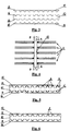
- Fig. 1 presents a building connector in the first embodiment of the invention, which uses five pairs of load bearing elements 1.
- the load bearing element 1 is presented in Fig. 7 and Fig. 8 , while a pair of load bearing elements 1 assembled together is presented in Fig. 9 and Fig. 10 .
- the same connector is presented in Fig. 2 , in an expanded view.
- Each pair of load bearing elements 1 includes two steel profiles 2, wherein reinforcing bars 3, 4 are attached to every steel profile 2.
- Load bearing elements 1 are located one above the other in every pair of load bearing elements 1.
- Fig. 7 to Fig. 10 indicate that a single load bearing element 1 comprises a section of a steel profile 2 with reinforcing bars 3, 4 attached to its both ends.
- every steel profile 2 is provided with four reinforcing bars 3, 4, two on each side of the profile.
- Reinforcing bars 3, 4 are attached such that they provide an extension of this profile section 2 on each side of the profile.
- the steel profile 2 comprises an open profile with an omega shape, wherein one steel reinforcing bar 3 is attached to at least one end of this steel profile 2, in the bends of its arms 5.
- the reinforcing bar 3 includes loop 6 and two arms within its length. These two arms of the reinforcing bar 3 provide an extension of the steel profile 2.
- the loop 6 of the reinforcing bar 3 covers the spine of the steel profile 2, as shown in Fig. 14 .
- the reinforcing bar 3 is welded to the steel profile 2 along the entire length of contact with this profile 2, within bends of this steel profile 2, between the outwards bent arm 5 of this steel profile 2 and the side wall 7 of the spine of this steel profile 2 perpendicular to arm 5.
- two reinforcing bars 4 are attached to the other end of the steel profile 2, providing an extension of said steel profile 2 in the opposite direction. This is shown in Fig. 7 and Fig. 8 .
- both load bearing elements 1 are located parallel to each other, one above the other, with spines of steel profiles 2 turned towards each other, such that the outwards bent arms 5 of both steel profiles 2 are located within parallel planes.
- the buckle 18 has an approximately semi-circular shape and is made of reinforcing bar.
- the buckle 18 of one of the profiles 2 is provided with a distancing tab 19, facilitating assembly of this pair of load bearing elements 1 at a construction site.
- the buckle 18 and the distancing tab 19 are shown in Fig. 10 and Fig. 12 .
- the thermal insulation layer 8 located between each pair of steel profiles 2 consists of three zones 9, 10, 11 in these embodiments of the invention, wherein the bottom insulation zone 9 preferably includes a ridge 12 matching the inner shape of the channel of the bottom steel profile 2. This is shown in Fig. 1, Fig. 2 and Fig. 3 .
- the middle insulation zone 10 on the other hand, includes a bottom channel 13 and a top channel 14 with shapes matching both profiles 2 within the insulation zone.
- the top insulation zone 11 preferably includes a protrusion 15 shaped to match the internal shape of the top steel profile 2. This is shown in the aforementioned figures.
- insulation zones 9, 10, 11 are provided as elongated bars in these embodiments of the invention, including multiple pairs of load bearing elements 2, forming a building connector according to the invention together with other load bearing elements 2.
- the bottom surface of the bottom insulation zone 9 and the top surface of the top insulation zone 11 are flat and both these surfaces cooperate in these embodiments of the invention with the bottom fire preventing plate 16 and the top fire preventing plate 17 of the connector, respectively. Plates 16, 17 are shown in Fig. 1 and Fig. 2 .
- Fig. 4 shows a connector according to Fig. 1 and Fig. 2 viewed from above, towards the fire preventing plate 17.
- the connector comprises five pairs of the described load bearing elements 1.
- Fig. 5 presents a cross-section through plane A-A marked in Fig. 4 , through zones of connection between reinforcing bars 3, 4 and steel profiles 2.
- Fig. 6 presents another cross-section B-B of Fig. 4 , a plane between these connection zones between bars 3, 4 and profiles 2, and the thermal insulation layer 8.
- Fig. 4 shows locations of the aforementioned cross-sections A-A and B-B.
- Fig. 5 and Fig. 6 show the A-A and B-B cross-sections of the connector in another embodiment of the invention.
- the omega-shaped steel profiles 2 are turned towards each other by their arms 5 instead of spines, as shown in other figures.
- the loop 6, not shown in the figures covers arms of the profile 2 instead of its spine. Additionally, buckles 18 were not used in this particular embodiment.
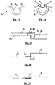
- Fig. 13 shows cross-section through a steel profile 2, which includes two arms 5 and two side walls 7.
- the term spine of the profile 2 used in this patent disclosure should be understood as two side walls 7, together with the base of this steel profile 2.
- Fig. 12 shows the spine of the profile 2 turned downwards.
- Fig. 14 presents the same cross-section of the steel profile 2 shown together with loop 6, covering the spine of the profile 2.
- the loop 6 is formed of reinforcing bar 3 and welded to the profile 2 at locations shown in the figure, where the profile 2 contacts the reinforcing bar 3. It is shown in the figure that loop 6 is continued as two straight sections of bar 3, comprising an extension of the steel profile 2. This is shown, for example, in Fig. 7 .
- the loop 6 does not cover the spine of the profile 2, but its arms, as in this embodiment of the invention, the profile 2 has its arms oriented towards the middle zone 10 of the insulation.
- the load bearing element 1 is a connection of a steel profile 2 with reinforcing bars 3, 4, wherein reinforcing bars 3, 4 are usually made of black steel and have flutted surface. Bars 3, 4 are provided in these embodiments of the invention as extensions of the steel profile 2.
- Such load bearing elements 1 are intended for use in connections, in which an external ferroconcrete element, such as a balcony slab, is installed on the same level as an internal ferroconcrete element, for example a floor slab.
- Fig. 15 to Fig. 21 present special embodiments of load bearing elements according to the invention.
- Fig. 15 shows a load bearing element intended for use in cases, in which an external, horizontal balcony slab 20 is installed above an internal floor slab 21 of a building.
- the reinforcing bar 4 intended to be fixed within the floor slab 21 located below the level of the balcony slab 20 has been folded four times into a loop, and its straight section has been introduced horizontally into the structure of the floor slab 21, below the second reinforcing bar 3 shown in the figure, located on the other side of the steel profile 2 and introduced into the balcony slab 20.
- This figure also shows the thermal insulation layer 8 and the ring beam 22 around the floor slab 21.
- the subsequent figures only show other, example embodiments of reinforcement bars 3, 4 in different mutual configurations of the external ferroconcrete element installed on an internal ferroconcrete element of a building.
- Fig. 16 Another embodiment of the load bearing element is presented in Fig. 16 .
- the load bearing element is intended for use in a case comprising an inversion of the example presented in Fig. 15 , namely, when the balcony slab is intended to be installed below the internal floor slab of the building.
- the reinforcing bar 4 intended to be placed within the floor slab, located above the balcony slab is folded four times and introduced into the floor slab structure located above the balcony slab.
- This figure and the subsequent figures do not show the balcony slab 20 and the floor slab 21, which are presented as an example in Fig. 15 .
- Fig. 17 shows a shape of the reinforcing bar 4, thanks to which collision of the bar with a Filigran-type ferroconcrete slab of the combined ceiling is avoided.
- the object of the invention is related to connections of all types of external ferroconcrete building elements with all types of internal ferroconcrete building elements, and not only to connections between balcony slabs and ferroconcrete floor slabs.
- FIG. 18 Another embodiment of the load bearing element according to the invention is presented in Fig. 18 .
- the reinforcement bar 4 cooperating with the internal element of a building has been formed as an element perpendicular to the reinforcement bar 3 cooperating with the balcony slab by folding the reinforcement bar 4 cooperating with this internal element of a building three times, into a loop.
- This type of load bearing elements is used to install the balcony slab onto a vertical, ferroconcrete wall of a building, above the balcony slab.
- Fig. 19 presents another embodiment of the load bearing element, intended to connect a horizontal balcony slab with a vertical, ferroconcrete wall of a building, located below the balcony slab.
- Bars 4 use to anchor the element in the vertical wall of the buildings are bent downwards, perpendicular to the steel profile 2 and to reinforcing bars 3 intended for anchoring within the balcony slab.
- Fig. 20 Another embodiment of the solution according to the invention is presented in Fig. 20 .
- the reinforcing bar 4 is intended for anchoring within a ferroconcrete ring beam of a brick wall.
- the load bearing element presented in Fig. 21 is intended for a similar purpose, with the exception that in this particular embodiment, reinforcing bars 4 intended for anchoring in the ferroconcrete ring beam of a brick wall are formed as loops by bending them three times.
- bars 3 intended for anchoring in a corner balcony slab, as shown in the Figure include level correction related to collision with bars of connectors located at the other side of the corner.
Landscapes
- Engineering & Computer Science (AREA)
- Architecture (AREA)
- Physics & Mathematics (AREA)
- Electromagnetism (AREA)
- Civil Engineering (AREA)
- Structural Engineering (AREA)
- Building Environments (AREA)
Abstract
Description
- This invention is related to a building connector with thermal insulation used to connect an external ferroconcrete element of a building, particularly provided as a balcony slab, with an internal ferroconcrete element of a building, for example with ferroconcrete ceiling, a ferroconcrete girder or a ferroconcrete ring beam of a masonry building.
- A range of building connector designs is known in the art, including solutions containing thermal insulation elements. A solution according to the international patent application
WO 00/47834 - According to another solution, known from the international patent application
WO 2017/121658 , the subject of the solution is a building element used to form connections between two parts of a buildings, thermally insulated from each other. This element includes a longitudinal part made of a thermally insulating material and is designed to be placed between building parts. This product includes bars penetrating the thermally insulated part. The elements are designed to be anchored within building parts being connected to each other. The goal of the product is to absorb stretching forces present between these elements of a single building. The goal of the product also includes development of solutions absorbing crushing and shearing forces present between the aforementioned building elements. According to this known solution, the building element includes metal bars, and non-metallic bars made of thermally insulating material. In this solution, metal bars are designed to hold the connection together, while it loses the stretching force absorbed by the non-metallic bars. - According to this solution, the building element used to connect two building parts to be thermally isolated from each other, includes a longitudinal element made of thermally insulating material, designed to be placed between building parts and steel bars penetrating the thermally insulating element. The bars are configured for anchoring in building parts to be connected and for being connected with reinforcement of the connected building parts. The bars absorb stretching forces between the listed building elements, measures used to absorb crushing and shearing forces between building elements. The aforementioned metal and non-metallic bars are made of thermally insulating material. According to this known solution, a non-metallic bar is placed on either side and close to each metal bar. The building element usually includes a group of three bars, a single, central, metal bar and two non-metallic bars absorbing crushing and shearing forces. The measures used to absorb crushing and shearing forces comprise supporting blocks in this case. Metal bars are made of steel in the case of this solution, while the composition of non-metallic bars is based on basalt.
- Another solution is also known, which uses pairs of C-shaped profiles penetrating a layer assembled using profiles made of a thermally insulating material. Each pair of the C-shaped profiles, the top and the bottom profile, is connected on one side using two U-shaped reinforcing bars and two U-shaped reinforcing bars on the other side. Two parallel, U-shaped bars are welded to the first arm ends of every C-shaped profile, and two similar, parallel U-shaped bars are welded to the second arm ends of every C-shaped profile. Below this C-shaped profile, two similar, parallel U-shaped bars are welded to the remaining U-shaped bar arms. The U-shaped bars thus welded to and on both sides of the C-shaped profiles provide bars extending these C-shaped profiles and welded to their arms. Four parallel arms of U-shaped bars connect the pair including the top and the bottom C-shaped profile within the end area of these C-shaped profiles. An identical connection using two more U-shaped bars is provided on the other side, in the second ends area of the same C-shaped profiles. Thus, a pair of C-shaped profiles is connected on each side using two U-shaped bars, wherein arms of these bars provide an extension of those C-shaped profiles. Thus placed four bar arms on one side of the pair of C-shaped profile are intended for connection with reinforcement of an external building element, for example of a balcony slab, while four bar arms on the opposite side of the same pair of C-shaped profiles are intended for connection with reinforcement of an internal building element, for example, of a ceiling. Each pair of the C-shaped profiles with the bars, the top and the bottom C-shaped profile, is free of reinforcing bars in the middle part of its length. A range of such pairs of C-shaped profiles with reinforcing bars, comprising connectors, is intended for installation between neighbouring edges of a balcony slab and of a building ceiling. C-shaped profiles in such a range of connector pairs are free of reinforcing elements in the middle part of their length. This area along the edge of the building ceiling and along the edge of the balcony slab is intended for installation of thermal insulation profiles in order to remove a potential thermal bridge. A bottom fire preventing bar is located under the row of the connectors described above in this known solution. The bottom C-shaped profiles and the bottom insulating bar rest on this fire preventing bar. The terms insulation used in this patent disclosure means thermal insulation used in construction industry to remove thermal bridges. The bottom insulating bar includes transverse channels for bottom C-shaped profiles, thus contacting the bottom fire preventing bar tightly. The middle insulating bar is placed on the bottom insulating bar, between the bottom and the top C-shaped profiles, on which the top insulating bar including channels for the top C-shaped profiles in its top surface is placed. The width of the bottom, middle and top bar is selected such that it provides adequate space between rows of U-shaped bar, enabling the bottom, middle and top insulating bars to be slipped below the top row of the C-shaped profiles and for lifting the system such that the top C-shaped profiles rest within the bar channels and enabling sliding in the direction parallel to the length of the C-shaped profiles. Thus prepared insulation placed between connectors in a row is covered by the top fire preventing bar. Once the boars of the described connectors are connected with the reinforcement of the balcony slab on one side and with the reinforcement of the floor slab on the other side, the entire connection, including the prepared insulation, maybe cast over with concrete.
- Known solutions usually use C-shaped profiles, T-shaped profiles or steel pipes reinforcing the connection point of the external building element, such as a balcony slab, for example, with the internal building element, such as a floor slab, for example. The aforementioned profile sections are usually extended on both sides using steel bars, often provided with cuts, enabling such elements to be bound to the reinforcement of the balcony slab on one side and to the ceiling reinforcement on the other. Thermal insulation is used in many solutions.
- The problem to be solved includes improving resistance of said connectors, achieving lower material consumption in such designs and improving thermal insulation through improvements including removal of thermal bridges in the discussed areas of connections of external building elements, such as balcony slabs, for example, with internal building elements, such as floor slabs, for example. The objective of the invention also includes easier assembly of the connectors.
- Most solutions known in the art and in the construction practice use steel bars in the discussed connections to transfer stretch forces, provided with with stainless steel bar sections in their middle parts. Shearing forces are transferred either using stretched steel bars as described above or concrete elements reinforced with steel fibres, protruding outside the insulation envelope.
- A building connector with thermal insulation according to the invention and according to claim 1 contains at least one pair of load bearing elements, one located above the other, and thermal insulation elements located around and between such load bearing elements. The connector is also provided with the top and the bottom fire preventing layer. A single load bearing element is provided as a steel profile section with steel reinforcing bars fixed to both its ends, providing extensions of such a profile, and the aforementioned steel profile section free of the reinforcing bars is placed between these reinforcing bars attached to both ends of the steel profile.
- The steel profile according to the invention is provided as an open profile with omega-type cross-section, with one steel reinforcing bar with a loop and two arms located along its length is attached to at least one end of this steel profile, at the bend of its arms. These two arms of the reinforcing bar provide an extension of the steel profile. The loop of this reinforcing bar covers the spine of the steel profile. The reinforcing bar is welded to the steel profile along the entire length of contact with this profile, within bends of this steel profile, between the outwards bent arm of this steel profile and the side wall of the spine of this steel profile perpendicular to said arm.
- Two reinforcing bars are preferably attached to the other end of the steel profile, providing an extension of said steel profile in the opposite direction.
- Within each pair of load bearing elements, both bearing elements are located parallel to each other, one above the other, with spines of steel profiles turned towards each other, such that the outwards bent arms of both steel profiles are preferably located within parallel planes.
- Within each pair of load bearing elements, the middle sections of both steel profiles are preferably located within the layer of thermal insulation, between connection points of the reinforcing bars.
- The thermal insulation layer located between every pair of steel profiles preferably consists of three zones, wherein the bottom insulation zone preferably includes a ridge matching the inner shape of the channel of the bottom steel profile. The middle insulation zone includes a bottom channel and the top channel with shapes matching both profiles within the insulation zone. The top insulation zone preferably includes a protrusion shaped to match the internal shape of the top steel profile.
- Insulation zones are preferably provided as elongated bars including multiple pairs of load bearing elements, forming a building connector together with other load bearing elements.
- The bottom surface of the bottom insulation zone and the top surface of the top insulation zone are flat and both these surfaces preferably cooperate with the bottom fire preventing plate and the top fire preventing plate of the connector, respectively.
- Reinforcement bars may be bent at a right angle at least on one side of the steel profile.
- In some embodiments of the invention, they may be shaped into a loop at the bends of reinforcing bars.
- Spines of both steel profiles may be connected with buckles on both sides of the insulation layer within a pair of load bearing elements.
- According to the invention presented in claim 1 and in the following claims, a new design of a building connector was proposed, by using an omega-shaped profile for the purpose. The use of this profile allowed reinforcing bars to be welded to the arms of such profiles, namely to bottom shelves and to side walls of these profiles. The presented design ensured significant technical improvement, for example, compared to connectors known in the art, using profiles without side arms. A single load bearing element design was proposed, including a reinforcing bar welded on one side, bent in the middle of its length into a loop covering the spine of the steel profile and a buckle on the other side, covering the spine of the second steel profile within the pair of load bearing elements.
- The stable support of reinforcing bars on the arms of omega-shaped profiles facilitated welding of reinforcing bars to the steel profile. Additionally, the use of the omega-shape profile, namely a C-shaped profile with side arms, provided significant improvement of mechanical resistance of the entire connector. It resulted in improved resistance of a single load bearing element and in improved resistance of anchoring of the entire load bearing element in concrete.
- Contrary to solutions known in the art, the invention provides a building connector, in which top load bearing elements are not connected to bottom load bearing elements, making transport and assembly of these elements with simultaneous placement of the intermediate insulation layer much easier.
- The solution according to the invention eliminated the problem of sliding thermal insulation elements between two layers of load-bearing elements connected with reinforcement, which was an obstacle during work on construction sites, when connectors known in the art where used.
- Installation of connectors according to the invention at constructor sites, or in a concrete pre-fabrication workshop, includes laying out individual layers in the following order:
- bottom fire preventing plate,
- bottom thermal insulation layer,
- bottom load bearing element layer,
- middle thermal insulation layer,
- top load bearing element layer,
- top thermal insulation layer,
- top fire preventing plate.
- Laying out these layers at the construction site proved to be easier and faster than installation of factory-assembled, ready-to-use, pre-fabricated connectors, inside which insulation elements are placed. The assembly of individual elements at the construction site described above increases matching precision of neighbouring connectors, providing further improvement of thermal insulation of the connection through better removal of thermal bridges. The solution according to the invention ensured improved resistance of load bearing elements by using the omega profile and facilitated assembly at construction sites by separating the top load bearing element and the bottom load bearing element. The problem of inaccurate assembly, in particular of thermal insulation elements, was removed in this solution, thus facilitating elimination of possible thermal bridges. It was shown that the use of omega-shaped profiles in the connector according to the invention resulted in a much higher force required to destroy the connector. Measurements performed at a research station allowed this force to be determined, for example, for an omega-shaped profile with 26mm height and the total width, including bent arms, of 58mm, made of 3mm thick stainless steel sheet, the force had a value of 55kN, wherein the setup included reinforcing bars with flutted surface, made of black steel, diameter 12mm.
- A range of known solutions includes technical limitations regarding the possibility of increasing the thickness of thermal insulation of the connector. It cannot be increased without a significant increase of the number of extremely cold, steel bars or relatively cold, concrete elements present within the connector. If the number, and thus - the size of load bearing elements, such as steel or concrete, was increased because of the increasing thickness of the connector, the thermal insulation balance of the connector could become unfavourable. Heat loss through cold load bearing elements could not be compensated by benefits offered by the increased insulation thickness. Additionally, increasing the number of stainless steel bar section would result in a much higher cost of the entire connector. The connector would then no longer be a price alternative to other methods of terrace insulation.
- An adequately selected stainless steel profile with an omega cross-section enables insulation thickness to be increased without increasing the number of profile pairs within 1 metre and without increasing the profile size.
- The object of the invention has been presented in embodiments in the attached drawing, in which individual figures of the drawing represent as follows:
-
Fig. 1 - a building connector including 5 pairs of load bearing elements, -
Fig. 2 - a connector according toFig. 1 in an expanded view, -
Fig. 3 - layout of insulation layers in an expanded view, -
Fig. 4 - a view of the connector according toFig. 1 and toFig. 2 from above, -
Fig. 5 - a cross-section through the connector according toFig. 4 along the A-A plane, passing through connections of steel profiles with reinforcing bars. -
Fig. 6 - a cross-section from the connector according toFig. 4 along the B-B plane passing through steel profiles, between the layer of thermal insulation and connections of steel profiles with reinforcing bars in another embodiment of the invention. -
Fig. 7 - a perspective view of a load bearing element. -
Fig. 8 - a side view of the load bearing element according toFig. 7 , -
Fig. 9 - a perspective view of a pair of load bearing elements, -
Fig. 10 - a side view of a pair of load bearing elements according toFig. 9 , -
Fig. 11 - a view of a pair of steel profiles with buckles, -
Fig. 12 - a side view of a pair of steel profiles according toFig. 11 , -
Fig. 13 - a view of the omega-type steel profile, -
Fig. 14 - a view of the profile according toFig. 13 , including a loop made of reinforcing wire, -
Fig. 15 - a view of a load bearing element in the third embodiment of the invention, including depiction of the balcony slab and of the floor slab. -
Fig. 16 - a view of a load bearing element in the fourth embodiment of the invention. -
Fig. 17 - a view of a load bearing element in the fifth embodiment of the invention. -
Fig. 18 - a view of a load bearing element in the sixth embodiment of the invention. -
Fig. 19 - a view of a load bearing element in the seventh embodiment of the invention. -
Fig. 20 - a view of a load bearing element in the eighth embodiment of the invention. -
Fig. 21 - a view of a load bearing element in the ninth embodiment of the invention. -
Fig. 1 presents a building connector in the first embodiment of the invention, which uses five pairs of load bearing elements 1. The load bearing element 1 is presented inFig. 7 and Fig. 8 , while a pair of load bearing elements 1 assembled together is presented inFig. 9 and Fig. 10 . The same connector is presented inFig. 2 , in an expanded view. - Each pair of load bearing elements 1 includes two
steel profiles 2, wherein reinforcingbars steel profile 2. Load bearing elements 1 are located one above the other in every pair of load bearing elements 1.Fig. 7 to Fig. 10 indicate that a single load bearing element 1 comprises a section of asteel profile 2 with reinforcingbars steel profile 2 is provided with four reinforcingbars bars profile section 2 on each side of the profile. -
Fig. 11 ,Fig. 13 and Fig. 14 show that thesteel profile 2 comprises an open profile with an omega shape, wherein onesteel reinforcing bar 3 is attached to at least one end of thissteel profile 2, in the bends of itsarms 5. In this embodiment of the invention, the reinforcingbar 3 includesloop 6 and two arms within its length. These two arms of the reinforcingbar 3 provide an extension of thesteel profile 2. Theloop 6 of the reinforcingbar 3 covers the spine of thesteel profile 2, as shown inFig. 14 . The reinforcingbar 3 is welded to thesteel profile 2 along the entire length of contact with thisprofile 2, within bends of thissteel profile 2, between the outwardsbent arm 5 of thissteel profile 2 and theside wall 7 of the spine of thissteel profile 2 perpendicular toarm 5. - In this embodiment of the invention, two reinforcing
bars 4 are attached to the other end of thesteel profile 2, providing an extension of saidsteel profile 2 in the opposite direction. This is shown inFig. 7 and Fig. 8 . - In this embodiment of the invention, as shown in
Fig. 9, Fig. 10, Fig. 11 and Fig. 12 , within each pair of load bearing elements 1, both load bearing elements 1 are located parallel to each other, one above the other, with spines ofsteel profiles 2 turned towards each other, such that the outwardsbent arms 5 of bothsteel profiles 2 are located within parallel planes. The load bearing profile 1, as shown inFig. 7 located on the side, on which two straight reinforcedbars 4 are attached, includes abuckle 18 attached onto the steel profile and coupling bothsteel profiles 2 together. Thebuckle 18 has an approximately semi-circular shape and is made of reinforcing bar. Within each pair ofprofiles 2, thebuckle 18 of one of theprofiles 2 is provided with adistancing tab 19, facilitating assembly of this pair of load bearing elements 1 at a construction site. Thebuckle 18 and thedistancing tab 19 are shown inFig. 10 and Fig. 12 . - Within each pair of load bearing elements 1, the middle sections of both
steel profiles 2 are located within the layer of thermal insulation 8, between connection points of the reinforcingbars - The thermal insulation layer 8 located between each pair of
steel profiles 2 consists of threezones bottom insulation zone 9 preferably includes a ridge 12 matching the inner shape of the channel of thebottom steel profile 2. This is shown inFig. 1, Fig. 2 andFig. 3 . Themiddle insulation zone 10, on the other hand, includes abottom channel 13 and atop channel 14 with shapes matching bothprofiles 2 within the insulation zone. Thetop insulation zone 11 preferably includes aprotrusion 15 shaped to match the internal shape of thetop steel profile 2. This is shown in the aforementioned figures. - As shown in
Fig. 3 ,insulation zones load bearing elements 2, forming a building connector according to the invention together with otherload bearing elements 2. - The bottom surface of the
bottom insulation zone 9 and the top surface of thetop insulation zone 11 are flat and both these surfaces cooperate in these embodiments of the invention with the bottomfire preventing plate 16 and the topfire preventing plate 17 of the connector, respectively.Plates Fig. 1 and Fig. 2 . -
Fig. 4 shows a connector according toFig. 1 and Fig. 2 viewed from above, towards thefire preventing plate 17. The connector comprises five pairs of the described load bearing elements 1.Fig. 5 presents a cross-section through plane A-A marked inFig. 4 , through zones of connection between reinforcingbars steel profiles 2.Fig. 6 presents another cross-section B-B ofFig. 4 , a plane between these connection zones betweenbars profiles 2, and the thermal insulation layer 8.Fig. 4 shows locations of the aforementioned cross-sections A-A and B-B. -
Fig. 5 and Fig. 6 show the A-A and B-B cross-sections of the connector in another embodiment of the invention. In this particular embodiment, the omega-shapedsteel profiles 2 are turned towards each other by theirarms 5 instead of spines, as shown in other figures. In this embodiment, theloop 6, not shown in the figures, covers arms of theprofile 2 instead of its spine. Additionally, buckles 18 were not used in this particular embodiment. -
Fig. 13 shows cross-section through asteel profile 2, which includes twoarms 5 and twoside walls 7. The term spine of theprofile 2 used in this patent disclosure should be understood as twoside walls 7, together with the base of thissteel profile 2.Fig. 12 shows the spine of theprofile 2 turned downwards. -
Fig. 14 presents the same cross-section of thesteel profile 2 shown together withloop 6, covering the spine of theprofile 2. Theloop 6 is formed of reinforcingbar 3 and welded to theprofile 2 at locations shown in the figure, where theprofile 2 contacts the reinforcingbar 3. It is shown in the figure thatloop 6 is continued as two straight sections ofbar 3, comprising an extension of thesteel profile 2. This is shown, for example, inFig. 7 . In the embodiment of the invention shown inFig. 5 and Fig. 6 , theloop 6 does not cover the spine of theprofile 2, but its arms, as in this embodiment of the invention, theprofile 2 has its arms oriented towards themiddle zone 10 of the insulation. - The proposed layout of
insulation zones - As shown in the attached figures,
Fig. 1 to Fig. 14 , the load bearing element 1 is a connection of asteel profile 2 with reinforcingbars bars Bars steel profile 2. Such load bearing elements 1 are intended for use in connections, in which an external ferroconcrete element, such as a balcony slab, is installed on the same level as an internal ferroconcrete element, for example a floor slab.Fig. 15 to Fig. 21 present special embodiments of load bearing elements according to the invention. -
Fig. 15 shows a load bearing element intended for use in cases, in which an external,horizontal balcony slab 20 is installed above aninternal floor slab 21 of a building. Thus, as shown inFig. 15 , the reinforcingbar 4 intended to be fixed within thefloor slab 21 located below the level of thebalcony slab 20 has been folded four times into a loop, and its straight section has been introduced horizontally into the structure of thefloor slab 21, below the second reinforcingbar 3 shown in the figure, located on the other side of thesteel profile 2 and introduced into thebalcony slab 20. This figure also shows the thermal insulation layer 8 and the ring beam 22 around thefloor slab 21. The subsequent figures only show other, example embodiments ofreinforcement bars - Another embodiment of the load bearing element is presented in
Fig. 16 . In this embodiment, the load bearing element is intended for use in a case comprising an inversion of the example presented inFig. 15 , namely, when the balcony slab is intended to be installed below the internal floor slab of the building. In this embodiment, the reinforcingbar 4 intended to be placed within the floor slab, located above the balcony slab, is folded four times and introduced into the floor slab structure located above the balcony slab. This figure and the subsequent figures do not show thebalcony slab 20 and thefloor slab 21, which are presented as an example inFig. 15 . -
Fig. 17 shows a shape of the reinforcingbar 4, thanks to which collision of the bar with a Filigran-type ferroconcrete slab of the combined ceiling is avoided. - Descriptions, such as balcony slab and floor slab, used in this disclosure, should be considered as examples. The object of the invention is related to connections of all types of external ferroconcrete building elements with all types of internal ferroconcrete building elements, and not only to connections between balcony slabs and ferroconcrete floor slabs.
- Another embodiment of the load bearing element according to the invention is presented in
Fig. 18 . Thereinforcement bar 4 cooperating with the internal element of a building has been formed as an element perpendicular to thereinforcement bar 3 cooperating with the balcony slab by folding thereinforcement bar 4 cooperating with this internal element of a building three times, into a loop. This type of load bearing elements is used to install the balcony slab onto a vertical, ferroconcrete wall of a building, above the balcony slab. -
Fig. 19 presents another embodiment of the load bearing element, intended to connect a horizontal balcony slab with a vertical, ferroconcrete wall of a building, located below the balcony slab.Bars 4 use to anchor the element in the vertical wall of the buildings are bent downwards, perpendicular to thesteel profile 2 and to reinforcingbars 3 intended for anchoring within the balcony slab. - Another embodiment of the solution according to the invention is presented in
Fig. 20 . In this embodiment, the reinforcingbar 4 is intended for anchoring within a ferroconcrete ring beam of a brick wall. The load bearing element presented inFig. 21 is intended for a similar purpose, with the exception that in this particular embodiment, reinforcingbars 4 intended for anchoring in the ferroconcrete ring beam of a brick wall are formed as loops by bending them three times. At the same time, bars 3 intended for anchoring in a corner balcony slab, as shown in the Figure, include level correction related to collision with bars of connectors located at the other side of the corner. -
- 1. Load bearing elements
- 2. Steel profile
- 3. Reinforcing bar
- 4. Reinforcing bar
- 5. Profile arm
- 6. Loop
- 7. Profile side wall
- 8. Insulating layer
- 9. Bottom insulation layer
- 10. Middle insulation layer
- 11. Top insulation layer
- 12. Ridge
- 13. Bottom channel
- 14. Top channel
- 15. Ridge
- 16. Bottom fire preventing plate
- 17. Top fire preventing plate
- 18. Buckle
- 19. Distancing tab
- 20. Balcony slab
- 21. Floor slab
- 22. Ring beam
Claims (10)
- Building connector with thermal insulation, including at least one pair of load bearing elements (1), one above the other, and a thermal insulation layer (8) around these load bearing elements (1) and between them, and containing a bottom and a top fire prevention layer (16,17), wherein the load bearing element is a section of a steel profile, on both ends of which steel reinforcement bars (3,4) comprising extensions of this profile (2) are attached, and a section of the steel profile (2) free of those reinforcement bars (3, 4) is located between these reinforcing bars (3,4) attached to both ends of the steel profile (2), characterised in that the steel profile (1) is an open profile with an omega cross-section, wherein a single steel reinforcing bar (3) is attached to at least one end of this steel profile (1), at the bends of its arms, which includes a loop (6) and two arms (5) formed along its length, such that loop (6) covers the spine of the steel profile (2) and this reinforcement bar (3) is welded to the steel profile (2) along the entire length of contact with this profile (2) at the bends of the steel profile (2), between the outwards bent arm (5) of this steel profile (2), and the side wall (7) of the spine of this profile (1) perpendicular to this arm (5).
- A building connector according to claim 1, characterised in that two reinforcing bars (4) are attached to the other end of the steel profile (2)
- A building connector according to claim 1, characterised in that within a pair of load bearing elements (1), both load bearing elements are located parallel to each other, one above the other, with spines of steel profiles (1) turned towards each other, such that the outwards bent arms (5) of both steel profiles (2) are located within parallel planes.
- A building connector according to claim 3, characterised in that within each pair of load bearing elements (1), the middle sections of both steel profiles (2) are located in the thermal insulation layer (8), between connection points of the reinforcing bars (3, 4).
- A building connector according to claim 4, characterised in that the thermal insulation layer (8) located between each pair of steel profiles (2) includes three insulation zones (9, 10, 11), with the bottom insulation zone (9) containing a ridge (12) with a shape matching the internal shape of the channel provided in the spine of the bottom profile (2), the middle insulation zone (10) contains a bottom channel (13) and a top channel (14) with shapes matching the shape of spines of both profiles (2) within the insulation zone, whilst the top insulation layer (11) contains a ridge (15) with a shape matching the interior of the spine of the top steel profile (2).
- A building connector according to claim 5, characterised in that insulation zones (9,10,11) comprise longitudinal girders covering multiple pairs of load bearing elements (1).
- A building connector according to claim 5 or 6, characterised in that the external surface of the bottom insulation zone (9) and the external surface of the top insulation zone (11) are flat and both these surfaces cooperate with the bottom fire preventing plate (16) and the top fire preventing plate (17), respectively.
- A building connector according to any of the claims 1 to 7, characterised in that the reinforcement bars (3, 4) are bent at the right angle at least on one side of the steel profile (2).
- A building connector according to claim 8, characterised in that the reinforcing bars (3, 4) are formed into a loop at the bends.
- A building connector according to any of claims 1 to 9, characterised in that within a pair of load bearing elements, spines of both steel profiles (2) are connected on both sides of the insulation layer (8) using buckles (18).
Priority Applications (1)
| Application Number | Priority Date | Filing Date | Title |
|---|---|---|---|
| EP18460050.0A EP3613910B1 (en) | 2018-08-22 | 2018-08-22 | Building connector with thermal insulation |
Applications Claiming Priority (1)
| Application Number | Priority Date | Filing Date | Title |
|---|---|---|---|
| EP18460050.0A EP3613910B1 (en) | 2018-08-22 | 2018-08-22 | Building connector with thermal insulation |
Publications (2)
| Publication Number | Publication Date |
|---|---|
| EP3613910A1 true EP3613910A1 (en) | 2020-02-26 |
| EP3613910B1 EP3613910B1 (en) | 2021-03-03 |
Family
ID=63878618
Family Applications (1)
| Application Number | Title | Priority Date | Filing Date |
|---|---|---|---|
| EP18460050.0A Not-in-force EP3613910B1 (en) | 2018-08-22 | 2018-08-22 | Building connector with thermal insulation |
Country Status (1)
| Country | Link |
|---|---|
| EP (1) | EP3613910B1 (en) |
Cited By (3)
| Publication number | Priority date | Publication date | Assignee | Title |
|---|---|---|---|---|
| EP4047147A1 (en) | 2021-02-19 | 2022-08-24 | iBALKON Dariusz Glaza | Construction reinforcement connector |
| EP4067593A1 (en) * | 2021-04-01 | 2022-10-05 | Leviat GmbH | Device for the subsequent thermal insulation, force-transmitting connection of a second load-bearing building element to a first load-bearing construction element and construction with such a device |
| EP4775751A1 (en) | 2025-01-14 | 2026-07-15 | Tipomega P.S.A. | Load-bearing frame of a construction connector |
Citations (5)
| Publication number | Priority date | Publication date | Assignee | Title |
|---|---|---|---|---|
| WO2000047834A1 (en) | 1999-02-12 | 2000-08-17 | Avi Alpenländische Veredelungs-Industrie Gesellschaft M.B.H. | Device for attaching cantilever plates to a wall construction or a ceiling construction |
| KR101462802B1 (en) * | 2013-07-26 | 2014-11-21 | 청원화학 주식회사 | Unit insulation product for blocking thermal bridge |
| FR3031529A1 (en) * | 2015-01-08 | 2016-07-15 | Keizh | PONCTUAL THERMAL BRIDGE BREAKER MODULE FOR OUTDOORALLY INSULATED BUILDINGS |
| CH711343A2 (en) * | 2015-07-20 | 2017-01-31 | Ikona Ag | Prefabricated building part with an insulation element for connecting a concrete cantilever plate to a concrete structure. |
| WO2017121658A1 (en) | 2016-01-12 | 2017-07-20 | Plakabeton S.A. | Construction element for connecting thermally insulated parts of a building |
-
2018
- 2018-08-22 EP EP18460050.0A patent/EP3613910B1/en not_active Not-in-force
Patent Citations (5)
| Publication number | Priority date | Publication date | Assignee | Title |
|---|---|---|---|---|
| WO2000047834A1 (en) | 1999-02-12 | 2000-08-17 | Avi Alpenländische Veredelungs-Industrie Gesellschaft M.B.H. | Device for attaching cantilever plates to a wall construction or a ceiling construction |
| KR101462802B1 (en) * | 2013-07-26 | 2014-11-21 | 청원화학 주식회사 | Unit insulation product for blocking thermal bridge |
| FR3031529A1 (en) * | 2015-01-08 | 2016-07-15 | Keizh | PONCTUAL THERMAL BRIDGE BREAKER MODULE FOR OUTDOORALLY INSULATED BUILDINGS |
| CH711343A2 (en) * | 2015-07-20 | 2017-01-31 | Ikona Ag | Prefabricated building part with an insulation element for connecting a concrete cantilever plate to a concrete structure. |
| WO2017121658A1 (en) | 2016-01-12 | 2017-07-20 | Plakabeton S.A. | Construction element for connecting thermally insulated parts of a building |
Cited By (4)
| Publication number | Priority date | Publication date | Assignee | Title |
|---|---|---|---|---|
| EP4047147A1 (en) | 2021-02-19 | 2022-08-24 | iBALKON Dariusz Glaza | Construction reinforcement connector |
| EP4067593A1 (en) * | 2021-04-01 | 2022-10-05 | Leviat GmbH | Device for the subsequent thermal insulation, force-transmitting connection of a second load-bearing building element to a first load-bearing construction element and construction with such a device |
| US12559931B2 (en) | 2021-04-01 | 2026-02-24 | Leviat GmbH | Device for thermally insulating, force-transmitting retrofitting of a second load-bearing construction element to a first load-bearing construction element and structure with such a device |
| EP4775751A1 (en) | 2025-01-14 | 2026-07-15 | Tipomega P.S.A. | Load-bearing frame of a construction connector |
Also Published As
| Publication number | Publication date |
|---|---|
| EP3613910B1 (en) | 2021-03-03 |
Similar Documents
| Publication | Publication Date | Title |
|---|---|---|
| KR900008987B1 (en) | Prefabricated module | |
| EP0169015B1 (en) | Composite floor system | |
| US8281534B2 (en) | Formed steel beam for steel-concrete composite beam and slab | |
| EP2556200B2 (en) | Open web grid runner | |
| KR102004419B1 (en) | Structure for reinforcing column using V-shaped ties | |
| EP3613910B1 (en) | Building connector with thermal insulation | |
| CN110067185B (en) | Steel pipe-steel plate combined web steel-concrete combined box girder | |
| NZ539238A (en) | A composite beam with reinforcing by shear connector to beam (typically steel beam) and mesh in concrete rib | |
| US4586307A (en) | Prefabricated ceiling element for ceilings in buildings | |
| KR101738244B1 (en) | Built-up beam having truss reinforcement | |
| US1898668A (en) | Floor construction or the like | |
| EP4047147B1 (en) | Construction reinforcement connector | |
| CA1225815A (en) | Construction element for thermal insulation in buildings | |
| KR102656176B1 (en) | A T-type unit using H-beam and a composite structure system with reduced floor height combined with a steel plate built-up composite column and composite beam | |
| US3440793A (en) | Girder/concrete combination | |
| KR102142185B1 (en) | Seismic reinforcement device of brick walls using masonry joint locking member and fixer and construction method using of the same | |
| KR101737573B1 (en) | Internal reinforced steel pipe girder | |
| KR100872959B1 (en) | Tsc beam formed with folded in top flanges | |
| SE516901C2 (en) | Prefabricated reinforced structural building elements, and stiffening plate elements for such construction | |
| RU2248433C1 (en) | Stationary falsework, method for assembling the latter and method for construction of monolithic walls and structures in stationary falsework | |
| WO2017081498A1 (en) | Lattice girder shaped with u profile braced with t steel elements or angle steel elements, and wall structure without thermal bridge created with this lattice girder | |
| KR20100004708A (en) | Length adjustable connector for two parallel insulation panel, and the insulation panel block using the same | |
| JP7658603B2 (en) | Deck Plates and Deck Plate Assemblies | |
| RU2826929C1 (en) | Hydraulic structure sheet piling wall distribution belt and method of its installation | |
| AU2013273739A1 (en) | Improved Bridge |
Legal Events
| Date | Code | Title | Description |
|---|---|---|---|
| PUAI | Public reference made under article 153(3) epc to a published international application that has entered the european phase |
Free format text: ORIGINAL CODE: 0009012 |
|
| STAA | Information on the status of an ep patent application or granted ep patent |
Free format text: STATUS: THE APPLICATION HAS BEEN PUBLISHED |
|
| AK | Designated contracting states |
Kind code of ref document: A1 Designated state(s): AL AT BE BG CH CY CZ DE DK EE ES FI FR GB GR HR HU IE IS IT LI LT LU LV MC MK MT NL NO PL PT RO RS SE SI SK SM TR |
|
| AX | Request for extension of the european patent |
Extension state: BA ME |
|
| STAA | Information on the status of an ep patent application or granted ep patent |
Free format text: STATUS: REQUEST FOR EXAMINATION WAS MADE |
|
| 17P | Request for examination filed |
Effective date: 20200714 |
|
| RBV | Designated contracting states (corrected) |
Designated state(s): AL AT BE BG CH CY CZ DE DK EE ES FI FR GB GR HR HU IE IS IT LI LT LU LV MC MK MT NL NO PL PT RO RS SE SI SK SM TR |
|
| RIC1 | Information provided on ipc code assigned before grant |
Ipc: E04B 1/00 20060101AFI20200820BHEP |
|
| GRAP | Despatch of communication of intention to grant a patent |
Free format text: ORIGINAL CODE: EPIDOSNIGR1 |
|
| STAA | Information on the status of an ep patent application or granted ep patent |
Free format text: STATUS: GRANT OF PATENT IS INTENDED |
|
| INTG | Intention to grant announced |
Effective date: 20201130 |
|
| GRAS | Grant fee paid |
Free format text: ORIGINAL CODE: EPIDOSNIGR3 |
|
| GRAA | (expected) grant |
Free format text: ORIGINAL CODE: 0009210 |
|
| STAA | Information on the status of an ep patent application or granted ep patent |
Free format text: STATUS: THE PATENT HAS BEEN GRANTED |
|
| AK | Designated contracting states |
Kind code of ref document: B1 Designated state(s): AL AT BE BG CH CY CZ DE DK EE ES FI FR GB GR HR HU IE IS IT LI LT LU LV MC MK MT NL NO PL PT RO RS SE SI SK SM TR |
|
| REG | Reference to a national code |
Ref country code: GB Ref legal event code: FG4D |
|
| REG | Reference to a national code |
Ref country code: AT Ref legal event code: REF Ref document number: 1367345 Country of ref document: AT Kind code of ref document: T Effective date: 20210315 Ref country code: CH Ref legal event code: EP |
|
| REG | Reference to a national code |
Ref country code: DE Ref legal event code: R096 Ref document number: 602018013351 Country of ref document: DE |
|
| REG | Reference to a national code |
Ref country code: IE Ref legal event code: FG4D |
|
| REG | Reference to a national code |
Ref country code: LT Ref legal event code: MG9D |
|
| PG25 | Lapsed in a contracting state [announced via postgrant information from national office to epo] |
Ref country code: GR Free format text: LAPSE BECAUSE OF FAILURE TO SUBMIT A TRANSLATION OF THE DESCRIPTION OR TO PAY THE FEE WITHIN THE PRESCRIBED TIME-LIMIT Effective date: 20210604 Ref country code: FI Free format text: LAPSE BECAUSE OF FAILURE TO SUBMIT A TRANSLATION OF THE DESCRIPTION OR TO PAY THE FEE WITHIN THE PRESCRIBED TIME-LIMIT Effective date: 20210303 Ref country code: HR Free format text: LAPSE BECAUSE OF FAILURE TO SUBMIT A TRANSLATION OF THE DESCRIPTION OR TO PAY THE FEE WITHIN THE PRESCRIBED TIME-LIMIT Effective date: 20210303 Ref country code: BG Free format text: LAPSE BECAUSE OF FAILURE TO SUBMIT A TRANSLATION OF THE DESCRIPTION OR TO PAY THE FEE WITHIN THE PRESCRIBED TIME-LIMIT Effective date: 20210603 Ref country code: NO Free format text: LAPSE BECAUSE OF FAILURE TO SUBMIT A TRANSLATION OF THE DESCRIPTION OR TO PAY THE FEE WITHIN THE PRESCRIBED TIME-LIMIT Effective date: 20210603 Ref country code: LT Free format text: LAPSE BECAUSE OF FAILURE TO SUBMIT A TRANSLATION OF THE DESCRIPTION OR TO PAY THE FEE WITHIN THE PRESCRIBED TIME-LIMIT Effective date: 20210303 |
|
| REG | Reference to a national code |
Ref country code: NL Ref legal event code: MP Effective date: 20210303 |
|
| REG | Reference to a national code |
Ref country code: AT Ref legal event code: MK05 Ref document number: 1367345 Country of ref document: AT Kind code of ref document: T Effective date: 20210303 |
|
| PG25 | Lapsed in a contracting state [announced via postgrant information from national office to epo] |
Ref country code: RS Free format text: LAPSE BECAUSE OF FAILURE TO SUBMIT A TRANSLATION OF THE DESCRIPTION OR TO PAY THE FEE WITHIN THE PRESCRIBED TIME-LIMIT Effective date: 20210303 Ref country code: PL Free format text: LAPSE BECAUSE OF FAILURE TO SUBMIT A TRANSLATION OF THE DESCRIPTION OR TO PAY THE FEE WITHIN THE PRESCRIBED TIME-LIMIT Effective date: 20210303 Ref country code: LV Free format text: LAPSE BECAUSE OF FAILURE TO SUBMIT A TRANSLATION OF THE DESCRIPTION OR TO PAY THE FEE WITHIN THE PRESCRIBED TIME-LIMIT Effective date: 20210303 Ref country code: SE Free format text: LAPSE BECAUSE OF FAILURE TO SUBMIT A TRANSLATION OF THE DESCRIPTION OR TO PAY THE FEE WITHIN THE PRESCRIBED TIME-LIMIT Effective date: 20210303 |
|
| PG25 | Lapsed in a contracting state [announced via postgrant information from national office to epo] |
Ref country code: NL Free format text: LAPSE BECAUSE OF FAILURE TO SUBMIT A TRANSLATION OF THE DESCRIPTION OR TO PAY THE FEE WITHIN THE PRESCRIBED TIME-LIMIT Effective date: 20210303 |
|
| PG25 | Lapsed in a contracting state [announced via postgrant information from national office to epo] |
Ref country code: EE Free format text: LAPSE BECAUSE OF FAILURE TO SUBMIT A TRANSLATION OF THE DESCRIPTION OR TO PAY THE FEE WITHIN THE PRESCRIBED TIME-LIMIT Effective date: 20210303 Ref country code: CZ Free format text: LAPSE BECAUSE OF FAILURE TO SUBMIT A TRANSLATION OF THE DESCRIPTION OR TO PAY THE FEE WITHIN THE PRESCRIBED TIME-LIMIT Effective date: 20210303 Ref country code: AT Free format text: LAPSE BECAUSE OF FAILURE TO SUBMIT A TRANSLATION OF THE DESCRIPTION OR TO PAY THE FEE WITHIN THE PRESCRIBED TIME-LIMIT Effective date: 20210303 Ref country code: SM Free format text: LAPSE BECAUSE OF FAILURE TO SUBMIT A TRANSLATION OF THE DESCRIPTION OR TO PAY THE FEE WITHIN THE PRESCRIBED TIME-LIMIT Effective date: 20210303 |
|
| PG25 | Lapsed in a contracting state [announced via postgrant information from national office to epo] |
Ref country code: PT Free format text: LAPSE BECAUSE OF FAILURE TO SUBMIT A TRANSLATION OF THE DESCRIPTION OR TO PAY THE FEE WITHIN THE PRESCRIBED TIME-LIMIT Effective date: 20210705 Ref country code: RO Free format text: LAPSE BECAUSE OF FAILURE TO SUBMIT A TRANSLATION OF THE DESCRIPTION OR TO PAY THE FEE WITHIN THE PRESCRIBED TIME-LIMIT Effective date: 20210303 Ref country code: SK Free format text: LAPSE BECAUSE OF FAILURE TO SUBMIT A TRANSLATION OF THE DESCRIPTION OR TO PAY THE FEE WITHIN THE PRESCRIBED TIME-LIMIT Effective date: 20210303 Ref country code: IS Free format text: LAPSE BECAUSE OF FAILURE TO SUBMIT A TRANSLATION OF THE DESCRIPTION OR TO PAY THE FEE WITHIN THE PRESCRIBED TIME-LIMIT Effective date: 20210703 |
|
| REG | Reference to a national code |
Ref country code: DE Ref legal event code: R097 Ref document number: 602018013351 Country of ref document: DE |
|
| PLBE | No opposition filed within time limit |
Free format text: ORIGINAL CODE: 0009261 |
|
| STAA | Information on the status of an ep patent application or granted ep patent |
Free format text: STATUS: NO OPPOSITION FILED WITHIN TIME LIMIT |
|
| PG25 | Lapsed in a contracting state [announced via postgrant information from national office to epo] |
Ref country code: AL Free format text: LAPSE BECAUSE OF FAILURE TO SUBMIT A TRANSLATION OF THE DESCRIPTION OR TO PAY THE FEE WITHIN THE PRESCRIBED TIME-LIMIT Effective date: 20210303 Ref country code: DK Free format text: LAPSE BECAUSE OF FAILURE TO SUBMIT A TRANSLATION OF THE DESCRIPTION OR TO PAY THE FEE WITHIN THE PRESCRIBED TIME-LIMIT Effective date: 20210303 Ref country code: ES Free format text: LAPSE BECAUSE OF FAILURE TO SUBMIT A TRANSLATION OF THE DESCRIPTION OR TO PAY THE FEE WITHIN THE PRESCRIBED TIME-LIMIT Effective date: 20210303 |
|
| 26N | No opposition filed |
Effective date: 20211206 |
|
| PG25 | Lapsed in a contracting state [announced via postgrant information from national office to epo] |
Ref country code: SI Free format text: LAPSE BECAUSE OF FAILURE TO SUBMIT A TRANSLATION OF THE DESCRIPTION OR TO PAY THE FEE WITHIN THE PRESCRIBED TIME-LIMIT Effective date: 20210303 |
|
| REG | Reference to a national code |
Ref country code: DE Ref legal event code: R119 Ref document number: 602018013351 Country of ref document: DE |
|
| REG | Reference to a national code |
Ref country code: CH Ref legal event code: PL |
|
| PG25 | Lapsed in a contracting state [announced via postgrant information from national office to epo] |
Ref country code: MC Free format text: LAPSE BECAUSE OF FAILURE TO SUBMIT A TRANSLATION OF THE DESCRIPTION OR TO PAY THE FEE WITHIN THE PRESCRIBED TIME-LIMIT Effective date: 20210303 |
|
| REG | Reference to a national code |
Ref country code: BE Ref legal event code: MM Effective date: 20210831 |
|
| PG25 | Lapsed in a contracting state [announced via postgrant information from national office to epo] |
Ref country code: LI Free format text: LAPSE BECAUSE OF NON-PAYMENT OF DUE FEES Effective date: 20210831 Ref country code: IT Free format text: LAPSE BECAUSE OF FAILURE TO SUBMIT A TRANSLATION OF THE DESCRIPTION OR TO PAY THE FEE WITHIN THE PRESCRIBED TIME-LIMIT Effective date: 20210303 Ref country code: CH Free format text: LAPSE BECAUSE OF NON-PAYMENT OF DUE FEES Effective date: 20210831 |
|
| PG25 | Lapsed in a contracting state [announced via postgrant information from national office to epo] |
Ref country code: IS Free format text: LAPSE BECAUSE OF FAILURE TO SUBMIT A TRANSLATION OF THE DESCRIPTION OR TO PAY THE FEE WITHIN THE PRESCRIBED TIME-LIMIT Effective date: 20210703 Ref country code: LU Free format text: LAPSE BECAUSE OF NON-PAYMENT OF DUE FEES Effective date: 20210822 |
|
| PG25 | Lapsed in a contracting state [announced via postgrant information from national office to epo] |
Ref country code: IE Free format text: LAPSE BECAUSE OF NON-PAYMENT OF DUE FEES Effective date: 20210822 Ref country code: FR Free format text: LAPSE BECAUSE OF NON-PAYMENT OF DUE FEES Effective date: 20210831 Ref country code: DE Free format text: LAPSE BECAUSE OF NON-PAYMENT OF DUE FEES Effective date: 20220301 Ref country code: BE Free format text: LAPSE BECAUSE OF NON-PAYMENT OF DUE FEES Effective date: 20210831 |
|
| GBPC | Gb: european patent ceased through non-payment of renewal fee |
Effective date: 20220822 |
|
| PG25 | Lapsed in a contracting state [announced via postgrant information from national office to epo] |
Ref country code: CY Free format text: LAPSE BECAUSE OF FAILURE TO SUBMIT A TRANSLATION OF THE DESCRIPTION OR TO PAY THE FEE WITHIN THE PRESCRIBED TIME-LIMIT Effective date: 20210303 |
|
| PG25 | Lapsed in a contracting state [announced via postgrant information from national office to epo] |
Ref country code: HU Free format text: LAPSE BECAUSE OF FAILURE TO SUBMIT A TRANSLATION OF THE DESCRIPTION OR TO PAY THE FEE WITHIN THE PRESCRIBED TIME-LIMIT; INVALID AB INITIO Effective date: 20180822 |
|
| PG25 | Lapsed in a contracting state [announced via postgrant information from national office to epo] |
Ref country code: GB Free format text: LAPSE BECAUSE OF NON-PAYMENT OF DUE FEES Effective date: 20220822 |
|
| PG25 | Lapsed in a contracting state [announced via postgrant information from national office to epo] |
Ref country code: MK Free format text: LAPSE BECAUSE OF FAILURE TO SUBMIT A TRANSLATION OF THE DESCRIPTION OR TO PAY THE FEE WITHIN THE PRESCRIBED TIME-LIMIT Effective date: 20210303 |
|
| PG25 | Lapsed in a contracting state [announced via postgrant information from national office to epo] |
Ref country code: MT Free format text: LAPSE BECAUSE OF FAILURE TO SUBMIT A TRANSLATION OF THE DESCRIPTION OR TO PAY THE FEE WITHIN THE PRESCRIBED TIME-LIMIT Effective date: 20210303 |
|
| PG25 | Lapsed in a contracting state [announced via postgrant information from national office to epo] |
Ref country code: TR Free format text: LAPSE BECAUSE OF FAILURE TO SUBMIT A TRANSLATION OF THE DESCRIPTION OR TO PAY THE FEE WITHIN THE PRESCRIBED TIME-LIMIT Effective date: 20210303 |