EP3613652A1 - Anti-rollover for harvesters with electronic steering - Google Patents
Anti-rollover for harvesters with electronic steering Download PDFInfo
- Publication number
- EP3613652A1 EP3613652A1 EP19188887.4A EP19188887A EP3613652A1 EP 3613652 A1 EP3613652 A1 EP 3613652A1 EP 19188887 A EP19188887 A EP 19188887A EP 3613652 A1 EP3613652 A1 EP 3613652A1
- Authority
- EP
- European Patent Office
- Prior art keywords
- steering
- machine
- rollover
- hmi
- steering angle
- Prior art date
- Legal status (The legal status is an assumption and is not a legal conclusion. Google has not performed a legal analysis and makes no representation as to the accuracy of the status listed.)
- Granted
Links
- 241001124569 Lycaenidae Species 0.000 title description 4
- 238000000034 method Methods 0.000 claims description 24
- 230000004044 response Effects 0.000 claims description 8
- 238000004364 calculation method Methods 0.000 claims description 4
- 230000005484 gravity Effects 0.000 claims description 3
- 230000005226 mechanical processes and functions Effects 0.000 claims description 3
- 230000009467 reduction Effects 0.000 description 37
- 230000006870 function Effects 0.000 description 25
- 238000010586 diagram Methods 0.000 description 12
- 238000004891 communication Methods 0.000 description 9
- 238000005516 engineering process Methods 0.000 description 5
- 230000008901 benefit Effects 0.000 description 4
- 230000006641 stabilisation Effects 0.000 description 4
- 238000011105 stabilization Methods 0.000 description 4
- 230000006399 behavior Effects 0.000 description 3
- 230000003993 interaction Effects 0.000 description 3
- 230000003287 optical effect Effects 0.000 description 3
- 238000003306 harvesting Methods 0.000 description 2
- 230000007246 mechanism Effects 0.000 description 2
- 230000008569 process Effects 0.000 description 2
- 239000004065 semiconductor Substances 0.000 description 2
- 230000003068 static effect Effects 0.000 description 2
- 230000004913 activation Effects 0.000 description 1
- 230000001413 cellular effect Effects 0.000 description 1
- 238000004590 computer program Methods 0.000 description 1
- 230000007423 decrease Effects 0.000 description 1
- 239000012530 fluid Substances 0.000 description 1
- 230000002706 hydrostatic effect Effects 0.000 description 1
- 230000010354 integration Effects 0.000 description 1
- 230000000116 mitigating effect Effects 0.000 description 1
- 230000004048 modification Effects 0.000 description 1
- 238000012986 modification Methods 0.000 description 1
- 230000002085 persistent effect Effects 0.000 description 1
- 230000002265 prevention Effects 0.000 description 1
- 230000035484 reaction time Effects 0.000 description 1
- 238000006467 substitution reaction Methods 0.000 description 1
- 230000001960 triggered effect Effects 0.000 description 1
- 230000000007 visual effect Effects 0.000 description 1
Images


Classifications
-
- B—PERFORMING OPERATIONS; TRANSPORTING
- B62—LAND VEHICLES FOR TRAVELLING OTHERWISE THAN ON RAILS
- B62D—MOTOR VEHICLES; TRAILERS
- B62D6/00—Arrangements for automatically controlling steering depending on driving conditions sensed and responded to, e.g. control circuits
- B62D6/002—Arrangements for automatically controlling steering depending on driving conditions sensed and responded to, e.g. control circuits computing target steering angles for front or rear wheels
-
- B—PERFORMING OPERATIONS; TRANSPORTING
- B60—VEHICLES IN GENERAL
- B60W—CONJOINT CONTROL OF VEHICLE SUB-UNITS OF DIFFERENT TYPE OR DIFFERENT FUNCTION; CONTROL SYSTEMS SPECIALLY ADAPTED FOR HYBRID VEHICLES; ROAD VEHICLE DRIVE CONTROL SYSTEMS FOR PURPOSES NOT RELATED TO THE CONTROL OF A PARTICULAR SUB-UNIT
- B60W30/00—Purposes of road vehicle drive control systems not related to the control of a particular sub-unit, e.g. of systems using conjoint control of vehicle sub-units
- B60W30/02—Control of vehicle driving stability
- B60W30/04—Control of vehicle driving stability related to roll-over prevention
-
- A—HUMAN NECESSITIES
- A01—AGRICULTURE; FORESTRY; ANIMAL HUSBANDRY; HUNTING; TRAPPING; FISHING
- A01D—HARVESTING; MOWING
- A01D41/00—Combines, i.e. harvesters or mowers combined with threshing devices
- A01D41/12—Details of combines
- A01D41/127—Control or measuring arrangements specially adapted for combines
- A01D41/1278—Control or measuring arrangements specially adapted for combines for automatic steering
-
- B—PERFORMING OPERATIONS; TRANSPORTING
- B60—VEHICLES IN GENERAL
- B60W—CONJOINT CONTROL OF VEHICLE SUB-UNITS OF DIFFERENT TYPE OR DIFFERENT FUNCTION; CONTROL SYSTEMS SPECIALLY ADAPTED FOR HYBRID VEHICLES; ROAD VEHICLE DRIVE CONTROL SYSTEMS FOR PURPOSES NOT RELATED TO THE CONTROL OF A PARTICULAR SUB-UNIT
- B60W10/00—Conjoint control of vehicle sub-units of different type or different function
- B60W10/20—Conjoint control of vehicle sub-units of different type or different function including control of steering systems
-
- B—PERFORMING OPERATIONS; TRANSPORTING
- B62—LAND VEHICLES FOR TRAVELLING OTHERWISE THAN ON RAILS
- B62D—MOTOR VEHICLES; TRAILERS
- B62D5/00—Power-assisted or power-driven steering
- B62D5/001—Mechanical components or aspects of steer-by-wire systems, not otherwise provided for in this maingroup
- B62D5/005—Mechanical components or aspects of steer-by-wire systems, not otherwise provided for in this maingroup means for generating torque on steering wheel or input member, e.g. feedback
-
- B—PERFORMING OPERATIONS; TRANSPORTING
- B62—LAND VEHICLES FOR TRAVELLING OTHERWISE THAN ON RAILS
- B62D—MOTOR VEHICLES; TRAILERS
- B62D6/00—Arrangements for automatically controlling steering depending on driving conditions sensed and responded to, e.g. control circuits
- B62D6/008—Control of feed-back to the steering input member, e.g. simulating road feel in steer-by-wire applications
-
- B—PERFORMING OPERATIONS; TRANSPORTING
- B60—VEHICLES IN GENERAL
- B60W—CONJOINT CONTROL OF VEHICLE SUB-UNITS OF DIFFERENT TYPE OR DIFFERENT FUNCTION; CONTROL SYSTEMS SPECIALLY ADAPTED FOR HYBRID VEHICLES; ROAD VEHICLE DRIVE CONTROL SYSTEMS FOR PURPOSES NOT RELATED TO THE CONTROL OF A PARTICULAR SUB-UNIT
- B60W2510/00—Input parameters relating to a particular sub-units
- B60W2510/20—Steering systems
Definitions
- the rollover risk reduction system 12 does not require an overlaid system or device, including those using ARC, SOA, and DSSI functionality.
- the rollover risk reduction system 12 comprises an HMI 14, a controller or electronic control unit (ECU) 16, a wheel angle sensor 18, a biasing device (bias) 20, steering valve 22, a ground speed sensor 24, and a machine inclination sensor 25 (e.g., inertial sensor).
- ECU electronice control unit
- biasing device biasing device
- steering valve 22 e.g., a ground speed sensor
- ground speed sensor 24 e.g., inertial sensor
- machine inclination sensor 25 e.g., inertial sensor.
- SOA functionality 34 comprises limiting the maximal steering angle set point in relationship to the machine ground speed according to equation 1 described above.
- a square value of the speed is calculated (36), and based on the geometry of the harvester 10 ( FIG. 1A ) (38), the maximum allowed steering angle ( ⁇ max) is calculated.
- the geometry includes the rear axle length or distance and the height of the center of mass of the harvester 10.
- the manner of connections among two or more components may be varied.
- the user interface 56 may be directly connected to the medium 72, and in communication with the controller 50 via the I/O interfaces 54.
- the HMI 76 may be directly coupled to the data bus 60.
- a computer-readable storage medium may comprise an electronic, magnetic, optical, or other physical device or apparatus that may contain or store a computer program (e.g., executable code or instructions) for use by or in connection with a computer-related system or method.
- an SOA method 68A implemented in one embodiment by the SOA module 68, comprises computing (calculating, computing and calculating used interchangeably herein) a square value of ground speed of the machine (90), and computing a maximum allowed steering angle according to the rollover equation (e.g., Equation 1) based on the square value of the ground speed and machine information (92).
- the machine information includes a length of a rear axle of the machine (e.g., harvester 10, FIG. 1A ) and a height at center of mass of the machine.
- the maximum allowed steering angle corresponding to a maximum (curvature) radius at a given speed without having a rollover condition.
- the SOA method 68A corresponds to the SOA functionality 34 of FIG. 4 .
- a DSSI method 70A implemented in one embodiment by the DSSI module 70, comprises applying a control equation to a non-linear set of curves that are proportional to machine speed to generate a dynamic steering input, the dynamic steering input comprising a dynamic counter-steer component (94), and providing the dynamic counter-steer component to a steering angle set point calculation (96).
- the counter-steer component causes a brief counter-steer (e.g., single step torque) response to a prior steering movement of the machine.
- the DSSI method 70A corresponds to the DSSI functionality 42 of FIG. 5 .
- one embodiment of the rollover risk reduction method 64A uses ARC 26 and SOA functionality 34 by: biasing a human-machine-interface to provide a force feedback to influence a human-machine-interface to a center position (102); causing rear wheels of the machine to maintain or return to straight forward travel (104); and limiting a steering angle of the machine, beyond which a rollover condition occurs, based on computation of a rollover equation with parameters corresponding to the input and machine geometry (106).
- the DSSI functionality 42 FIG. 5
- the causing of the rear wheels to maintain or return to a straight forward travel may be achieved via the ARC module 66, executed by the processor 52, feeding input (e.g., steering angle set-point) to the actuator 80 of the steering valve, which in turn fluidly communicates with the hydraulic circuit of the steering system (e.g., cylinders of the rear wheels, hydraulic pump, etc.) to cause the alignment of the rear wheels.
- input e.g., steering angle set-point
- references to “one embodiment”, “an embodiment”, or “embodiments” mean that the feature or features being referred to are included in at least one embodiment of the technology.
- references to “one embodiment”, “an embodiment”, or “embodiments” in this description do not necessarily refer to the same embodiment and are also not mutually exclusive unless so stated and/or except as will be readily apparent to those skilled in the art from the description.
- a feature, structure, act, etc. described in one embodiment may also be included in other embodiments, but is not necessarily included.
- the present technology can include a variety of combinations and/or integrations of the embodiments described herein.
Landscapes
- Engineering & Computer Science (AREA)
- Transportation (AREA)
- Mechanical Engineering (AREA)
- Chemical & Material Sciences (AREA)
- Combustion & Propulsion (AREA)
- Automation & Control Theory (AREA)
- Life Sciences & Earth Sciences (AREA)
- Environmental Sciences (AREA)
- Physics & Mathematics (AREA)
- Mathematical Physics (AREA)
- Steering Control In Accordance With Driving Conditions (AREA)
- Guiding Agricultural Machines (AREA)
Abstract
Description
- This application claims the benefit of
U.S. Provisional Application No. 62/721,100, filed August 22, 2018 - The present disclosure is generally related to harvesting machines, and, in particular, harvesting machines that use steer-by-wire technology.
- Combine harvesters are machines with rear wheel steering systems. These machines are naturally unstable at higher speed due to their tendency to oversteer. Combine harvesters also possess a high center of gravity. If an operator is not fully concentrated, the instability created by the machine dynamics of rear wheel steering combined with the high position of center of mass of the combine harvester may lead to a rollover event when the combine harvester travels at higher speeds. For instance, combine harvesters have a tendency to rollover in case of over-steering during an evasive maneuver at higher speed on road conditions.
- In case of machines with conventional hydrostatic steering, due to adjustments in the relationship between steering wheel turns and wheel angle, an over-steering situation can be naturally avoided. In case of an electronically controlled steering system (steer-by-wire), the reaction times are faster and, without any additional electronic measures, an over-steering situation can easily result.
- Different proposals to improve dynamic stability are known, but they are normally considered for a machine with a conventional steering wheel and steering column and with an overlaid electro-hydraulic device. Dynamic stabilization of automotive vehicles is also known, but due to the steering mechanism characteristics, an overlaid system is necessary.
- Many aspects of the disclosure can be better understood with reference to the following drawings. The components in the drawings are not necessarily to scale, emphasis instead being placed upon clearly illustrating the principles of the present disclosure. Moreover, in the drawings, like reference numerals designate corresponding parts throughout the several views.
-
FIGS. 1A-1B are schematic diagrams that illustrate forces applied to a combine harvester during cornering that are considered in an embodiment of a rollover risk reduction system. -
FIG. 2 is a block diagram that illustrates an embodiment of an example rollover risk reduction system. -
FIG. 3 is a schematic diagram that conceptually illustrates example rollover risk reduction system logic that implements active return to center (ARC) functionality. -
FIG. 4 is a schematic diagram that conceptually illustrates example rollover risk reduction system logic that implements oversteering avoidance (SOA) functionality. -
FIG. 5 is a schematic diagram that conceptually illustrates example rollover risk reduction system logic that implements dynamic stabilization with steering inputs (DSSI) functionality. -
FIG. 6 is a block diagram that illustrates an embodiment of an example controller used in an embodiment of a rollover risk reduction system. -
FIG. 7 is a flow diagram that illustrates an embodiment of an example ARC method. -
FIG. 8 is a flow diagram that illustrates an embodiment of an example SOA method. -
FIG. 9 is a flow diagram that illustrates an embodiment of an example DSSI method. -
FIG. 10 is a flow diagram that illustrates an embodiment of an example rollover risk reduction method using a combination of at least ARC and SOA methods. - In one embodiment, a steering system for a machine, the steering system comprising: a steer-by-wire system configured to provide rear wheel based steering, the steer-by-wire system comprising: a human-machine-interface (HMI) configured to provide a force feedback to the HMI that influences the HMI to a center position; plural sensors; and one or more controllers configured by executable code to receive input from one or more of the plural sensors and reduce a risk of rollover by: causing the rear wheels to maintain or return to straight forward travel in conjunction with the force feedback; and limiting a steering angle of the machine, beyond which a rollover condition occurs, based on computation of a rollover equation with parameters corresponding to the input and machine geometry.
- Certain embodiments of a rollover risk reduction system are disclosed that combine plural electronic functions to avoid or generally, reduce the risk of a rollover event for a rear wheel (electronic) steering-based, moving machine, the electronic functions including any combination of active return to center (ARC), static over-steering avoidance (SOA), and dynamic stabilization with steering inputs (DSSI). In general, the ARC function influences the HMI towards the center while straightening out the harvester, the SOA function electronically limits the turning radius of the harvester according to the speed of the harvester, and the DSSI function causes a fast reflection (e.g., in a manner that may be transparent to the operator) of the steering angle to create a torque that counters a preceding steering movement. In the various embodiments described herein, a combine harvester is illustrative of an example rear wheel steering-based, moving machine, with steering achieved using an electronic steering system comprising steer-by-wire technology. As set forth in detail below, certain embodiments of a rollover risk reduction system contemplates that the combine harvester (hereinafter, referred to also as a harvester) is driven exclusively or primarily by electronic commands provided by an operator, the electronic commands generated based on direct operator interaction with a human-machine-interface (HMI). The HMI may be embodied in one of several types of forms, including as a joystick, mini-wheel, etc. The HMI is configured with a force-feedback function corresponding to return-to-center capabilities of the steering system enabled via ARC functionality. One or more controllers are used to adjust the position of the steerable wheels according to a steering angle set-point. Further, certain embodiments of a rollover risk reduction system do not need additional overlaid devices added to the available electronic steering system.
- Digressing briefly, rear-wheel steering systems possess inherent instability issues at high speeds, particularly when used in mobile machines (hereinafter, referred to simply as machines, with the explanation below using a harvester as an illustrative example) that have a high center of mass. In contrast, certain embodiments of a rollover risk reduction system use the physics of when a rollover event commences to generate two or more electronic rollover countering functions to reduce the risk of a rollover event, with an added benefit of doing so without the need for an overlaid device.
- Having summarized certain features of a rollover risk reduction system of the present disclosure, reference will now be made in detail to the description of a rollover risk reduction system as illustrated in the drawings. While a rollover risk reduction system will be described in connection with these drawings, there is no intent to limit it to the embodiment or embodiments disclosed herein. For instance, in the description that follows, though focus is on the implementation in a harvester, it should be appreciated by one having ordinary skill in the art that for some embodiments other mobile machines that use rear wheel electronic steering, particularly such machines with a high center of mass, may also benefit from the disclosed embodiments, and hence are contemplated to be within the scope of the invention. Further, although the description identifies or describes specifics of one or more embodiments, such specifics are not necessarily part of every embodiment, nor are all various stated advantages necessarily associated with a single embodiment or all embodiments. On the contrary, the intent is to cover all alternatives, modifications and equivalents included within the scope of the disclosure as defined by the appended claims. Further, it should be appreciated in the context of the present disclosure that the claims are not necessarily limited to the particular embodiments set out in the description.
- Note that reference herein to steering control is to be understood as steering control characterized primarily by direct operator intervention with the HMI, as opposed to what may be characterized primarily as machine or satellite guided control. Note also that references hereinafter made to certain directions, such as, for example, "front", "rear", "left" and "right", are made as viewed from the rear of a harvester looking forwardly.
- Referring now to
FIGS. 1A-1B , shown is an illustration of aharvester 10 and various forces applied to theharvester 10 during cornering. The involved dimensions include axle distance or length (d), height (h) of a center of mass (CM) for theharvester 10, and curvature (χ) performed by the harvester, the latter which can be considered the inverse of a curvature radius (r). With theharvester 10 cornering at ground speed (v), a centrifugal force (CF) can be considered applied to its center of mass (CM). In this situation, the normal forces N1 and N2, which are normally equal when theharvester 10 is following a straight path, become uneven and theharvester 10 tends to rollover with a roll angle (θ), as illustrated inFIG. 1B . When the rollover event starts, N1 goes to zero. At this instant, the overturning curve radius is proportional to the square of the harvester speed, as set forth in the following (rollover) equation 1:
where g represents earth gravity (approximately 9.8 meters per second squared). - Having described the example forces experienced by the
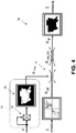
harvester 10 leading up to a rollover event, attention is directed toFIG. 2 , which illustrates an embodiment of an example rolloverrisk reduction system 12. It should be appreciated by one having ordinary skill in the art that the rolloverrisk reduction system 12 illustrated inFIG. 2 is merely illustrative of example rollover risk reduction functionality, and that some embodiments may include different features (e.g., additional or fewer features). For instance, the rolloverrisk reduction system 12 may be implemented as a fail operational system, which implies that there is redundancy in components (e.g., duplication in logic, steering valves, sensors, steering pumps, etc.) to ensure that the system operates safely and in a similar manner regardless of failure of a single component. Notably, certain embodiments of a rolloverrisk reduction system 12 do not require an overlaid system or device, including those using ARC, SOA, and DSSI functionality. In the depicted embodiment, the rolloverrisk reduction system 12 comprises anHMI 14, a controller or electronic control unit (ECU) 16, awheel angle sensor 18, a biasing device (bias) 20,steering valve 22, aground speed sensor 24, and a machine inclination sensor 25 (e.g., inertial sensor). Note that there may be additional components in some embodiments, as described above, including one or more controllers that cooperate to enable functionality of the rolloverrisk reduction system 12 and/or additional sensors, or fewer components (e.g. omission of themachine inclination sensor 25, for instance in embodiments where the DSSI functionality is omitted, or where functionality is combined in a single device). - The
HMI 14 enables direct operator interaction with steering control logic of the harvester 10 (FIG. 1A ), and may include a joystick, mini-wheel, among other devices that enable operator intervention. TheHMI 14 converts the manipulations of the HMI by the operator into electronic steering commands submitted to theECU 16, which in turn provides commands to the steeringvalve 22 to control the steering cylinder for rear wheel control. Note that in some embodiments, theHMI 14 may enable activation of additional machine functions via operator input to one or more controls (e.g., buttons, switches, knobs, etc.) located on theHMI 14. - The biasing
device 20 provides for a force-feedback function for theHMI 14, and may include an electromagnetic motor, spring, resilient device, among other devices. The biasingdevice 20 andHMI 14 cooperate with theECU 16 to enable a force-feedback function of the ARC functionality, as explained further below. In some embodiments, the biasingdevice 20 may be incorporated in theHMI 14. - The
wheel angle sensor 18 detects the angle of the rear wheel, and hence is generally proximal to the rear wheel of the harvester 10 (FIG. 1A ). In some embodiments, there may be awheel angle sensor 18 for each rear wheel of the harvester 10 (FIG. 1A ). Thewheel angle sensor 18 may be embodied as an analog device (e.g., with steering angles corresponding to voltage differences) or a digital device (e.g., non-contact device, such as an optical sensor) that detects the rate of turn and angular position. - The
ground speed sensor 24 is used to detect the ground speed or velocity of the harvester 10 (FIG. 1A ), and may be embodied as a shaft encoder, radar device, photoelectric device, or other device (e.g., global navigation satellite system (GNSS) receiver), as is known. - The
machine inclination sensor 25 senses the inclination of the harvester 10 (FIG. 1A ), such as for use in the DSSI functionality, and may include an inclinometer, or inertial components (e.g., gyroscope) located in, for instance, a GNSS receiver of theharvester 10. - The steering
valve 22 is used in cooperation with a hydraulic circuit that includes, among other known components, one or more steering pumps, reservoir, relief valve, etc. and which comprises an actuator that receives input from theECU 16 to enable steering control via fluidic (hydraulic fluid) interaction with a steering cylinder controlling the rear wheel steering. - Electronic communications among the various components of the rollover
risk reduction system 12 may be achieved over a controller area network (CAN) bus or via a communications medium using other standard or proprietary communication protocols (e.g., RS 232, etc.). Communication may be achieved over a wired medium, wireless medium, or a combination of wired and wireless media. - The
ECU 16 provides the steering control logic for ARC, SOA, and DSSI functionality, and is explained further below. -
FIGS. 3-5 conceptually illustrate respective functionality of firmware/software and/or hardware of certain embodiments of a rollover risk reduction system that enable the prevention or mitigation of risk of a rollover event, withFIG. 3 illustrating ARC functionality,FIG. 4 illustrating (along with ARC functionality) SOA functionality, andFIG. 5 illustrating (along with ARC and SOA functionality) DSSI functionality. It should be appreciated by one skilled in the art that certain embodiments may utilize any combination of ARC, SOA, or DSSI functionality. - Referring to
FIG. 3 , shown is a conceptual illustration ofARC functionality 26 carried out by the ECU 16 (FIG. 2 ) in cooperation with other components of the rolloverrisk reduction system 12 illustrated inFIG. 2 . In one embodiment, a first step to stabilize the harvester 10 (FIG. 1A ) is to eliminate, electronically, the natural behavior of a rear-steering machine to oversteer at high speeds in road conditions. By the use of an HMI 14 (FIG. 2 ) with a force-feedback mechanism used in conjunction with return-to-center capability, this can be achieved. TheHMI 14, in cooperation with the biasingdevice 20, provides a force (e.g., torque) that the operator experiences when handling theHMI 14. The force effectively tries to bring theHMI 14 to the central position. For instance, if the operator withdraws his or her hand from theHMI 14 upon negotiating theharvester 10 along a curve, theHMI 14 returns to a central position. Similarly, an operator in contact with theHMI 14 feels that force influencing the position of theHMI 14 to the center position. In conjunction with the force presented by the HMI 14 (e.g., via the biasing device 20), the steerable wheels of theharvester 10 also align with the harvester 10 (via the steer-by-wire system used in the harvester 10), with the result that theharvester 10 exhibits a "natural" or car suspension-like behavior that follow a straight-ahead path. The force varies according to the harvester speed (as determined, for instance, from the ground speed sensor 24 (FIG. 2 )) based on a torque set-point provided by the ECU 16 (FIG. 1A ). This force feedback feature and alignment to follow the straight-ahead path is referred to herein as an Active-Return-to-Center (ARC) capability. - As depicted conceptually in
FIG. 3 , the operator provides a steering command (ε) that generates a steering angle reference value (αref) (28). The software function depicted in (28) reveals curves conceptually illustrating a relationship between the HMI movement a steering angle reference that is nonlinear and varies according to speed, with the output to the steering valve control provided by theECU 16 in conjunction with the steering valve 22 (FIG. 1A ) and steering cylinder. Also, the curves of the software function represent a torque profile that an operator physically experiences via theHMI 14/biasing device 20 (FIG. 1A ) according to a force feedback function. The force the operator feels varies depending on the speed of the harvester 10 (FIG. 1A ). Once electronically limited to a maximum steering angle provided by the mechanical steering system (αmec_lim) (30) (the limit representing an end of stroke of the steering system that is stored in memory (e.g., ECU memory) during a calibration stage), the final steering angle set point (αsp) is provided to the steering angle controller (e.g., ECU 16) that in one embodiment is part of theharvester 10 ofFIG. 1A (32). Theharvester 10 corners with a curvature (χ). Due to the ARC capability, once the operator releases theHMI 14, theharvester 10 returns to a straight-ahead path. - Referring to
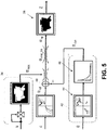
FIG. 4 , shown is a conceptual illustration of oversteering avoidance (SOA)functionality 34. As explained above, theSOA functionality 34 is shown combined with theARC functionality 26, though in some embodiments, theSOA functionality 34 andARC functionality 26 may not be combined in an embodiment of a rollover risk reduction system.SOA functionality 34 comprises limiting the maximal steering angle set point in relationship to the machine ground speed according toequation 1 described above. In one embodiment, a square value of the speed is calculated (36), and based on the geometry of the harvester 10 (FIG. 1A ) (38), the maximum allowed steering angle (αmax) is calculated. In one embodiment, the geometry includes the rear axle length or distance and the height of the center of mass of theharvester 10. This value (αmax) is used in a limiter (40) to set a boundary to the original reference value (αref) provided by the HMI 14 (FIG. 2 ). Note that the geometry may be input (e.g., in a graphical user interface screen) by the operator, or accessed from local (or remote) memory. -
FIG. 5 conceptually illustrates dynamic stabilization with steering inputs (DSSI)functionality 42. AlthoughDSSI functionality 42 is depicted in combination withARC functionality 26 andSOA functionality 34, some embodiments may omitARC functionality 26 orSOA functionality 34. Digressing briefly, in some extreme corner conditions, even withARC functionality 26 and/orSOA functionality 34 in place, the static stability of a rear wheel steering machine has limits. To increase, even more, the anti-rollover behavior of such machines, a dynamic software component may be added to the system. In one embodiment, a DSSI subset of functions (42) calculates this component, providing an overlaid software function (and hence no additional hardware) that provides an additional component to a steer-by-wire, steering angle set-point. The DSSI consists of a non-linear set of curves (44) proportional to the harvester speed (v) that creates an overlaid steering command after a certain rollover angle (θlim) is reached. Note that the input θ may be received via the machine inclination sensor 25 (FIG. 1A ), which in some embodiments may be an inertial component of a GNSS receiver. As depicted in thesoftware function 44, there is a respective x (input) and y (output) axis and nonlinear curves that convey that, at the input of a specific (e.g., threshold) roll angle theta (θ), thesoftware function 44 is triggered, providing a high input value to thesoftware function 46. That is, to achieve immediate and fast response, an outcome of the function 44 (e.g., curves) goes through a control equation (46) (e.g., derivative with temporary lag mathematical equation or DT1) that should be tuned accordingly (e.g., to determine the size or magnitude of a response that is appropriate for the condition). In other words,software function 46 illustrates a timely step response that decreases slowly until it disappears, collectively representing a counter-steer movement that the steering system has to achieve. Note that for higher rollover angles, the higher the trigger and counter-steer response. The result of thisfunction 46 is a dynamic steering input (αdyn) that is added to the system (48) (e.g., counter-steer movement is added to the steering angle set-point). For instance, the dynamic steering input provides a single step or pulse response (e.g., torque response corresponding to a counter-steer) to the steering movement in a way that the center of mass (CM) of the harvester 10 (FIG. 1A ) is pushed back to its stable position, avoiding a rollover event. - Having described various ARC, SOA, and DSSI functionality of certain embodiments of a rollover risk reduction system, attention is now directed to
FIG. 6 , which illustrates an embodiment of anexample controller 50 that may be used in an embodiment of a rollover risk reduction system. Though emphasis in this disclosure is on the use of asingle controller 50, in some embodiments, functionality of a rollover risk reduction system may be achieved through the use of plural controllers operating under distributed control. As explained above, redundancy may be implemented, where for operations satisfied using a single controller, two or more controllers may be used to enable redundancy. Similarly, where operation is satisfied using two or more controllers operating in a distributed manner (e.g., peer-to-peer, master-slave, etc.), redundancy is achieved using four or more controllers, respectively. One having ordinary skill in the art should appreciate in the context of the present disclosure that theexample controller 50 is merely illustrative, and that some embodiments of thecontroller 50 may comprise fewer or additional components, and/or some of the functionality associated with the various components depicted inFIG. 6 may be combined, or further distributed among additional modules, in some embodiments. In some embodiments, functionality of modules described herein may be implemented as software, hardware, or a combination of software and hardware. In some embodiments, functionality of thecontroller 50 may be implemented according to other types of devices, including a programmable logic controller (PLC), FPGA device, ASIC device, among other devices. It should be appreciated that certain well-known components of computer devices are omitted here to avoid obfuscating relevant features of thecontroller 50. - In one embodiment, the
controller 50 comprises one or more processors, such asprocessor 52, input/output (I/O) interface(s) 54, a user interface (UI) 56, andmemory 58, all coupled to one or more data busses, such as data bus 60. - The
memory 58 may include any one or a combination of volatile memory elements (e.g., random-access memory RAM, such as DRAM, and SRAM, etc.) and nonvolatile memory elements (e.g., ROM, hard drive, tape, CDROM, etc.). Thememory 58 may store a native operating system, one or more native applications, emulation systems, or emulated applications for any of a variety of operating systems and/or emulated hardware platforms, emulated operating systems, etc. In the embodiment depicted inFIG. 6 , thememory 58 comprises anoperating system 62 and rolloverrisk reduction software 64. In one embodiment, the rolloverrisk reduction software 64 comprises anARC module 66, anSOA module 68, and aDSSI module 70. It should be appreciated by one having ordinary skill in the art that in some embodiments, additional or fewer software modules (e.g., combined functionality) may be employed in thememory 58 or additional memory. In some embodiments, a separate storage device may be coupled to the data bus 60, such as a persistent memory (e.g., optical, magnetic, and/or semiconductor memory and associated drives). - The
processor 52 may be embodied as a custom-made or commercially available processor, a central processing unit (CPU) or an auxiliary processor among several processors, a semiconductor based microprocessor (in the form of a microchip), a macroprocessor, one or more application specific integrated circuits (ASICs), a plurality of suitably configured digital logic gates, and/or other well-known electrical configurations comprising discrete elements both individually and in various combinations to coordinate the overall operation of thecontroller 50. - The I/O interfaces 54 provide one or more interfaces to a network comprising a
communication medium 72, which may be a wired medium (e.g., controller area network (CAN) bus) as depicted inFIG. 6 , a wireless medium (e.g., Bluetooth channel(s)), or a combination of wired and wireless mediums or media, as explained similarly above in association withFIG. 2 . In other words, the I/O interfaces 54 may comprise any number of interfaces for the input and output of signals (e.g., analog or digital data) for conveyance over one or more communication mediums. In the depicted embodiment,plural sensors 74, anHMI 76, aGNSS receiver 78, and an actuator 80 (e.g., solenoid, for the steeringvalve 22 described in association withFIG. 2 ) are coupled to the medium 72, enabling communication of signals/data with thecontroller 50 via the I/O interfaces 54. In one embodiment, thesensors 74 comprise thewheel angle sensor 18, theground speed sensor 24, and/or themachine inclination sensor 25 described in association with, and illustrated in,FIG. 2 , and theHMI 76 is similar to the HMI 14 (FIG. 2 ). As explained above, themachine inclination sensor 25 may be embodied as an inertial component (e.g., gyroscope) of theGNSS receiver 78. In some embodiments, the biasing device 20 (FIG. 2 ) is included with the HMI 76 (as shown in the dashed box labeled "bias" inFIG. 6 ). In some embodiments, additional components may be coupled to the medium 72, including other sensors, other controllers, other actuators, and/or telephony/radio components (e.g., cellular and/or radio frequency (RF) modem), the latter enabling communications with other networks, systems or devices external to the harvester 10 (FIG. 1A ). - The user interface (UI) 56 may be an interface that is separate and additional to the
HMI 76, including a keyboard, mouse, microphone, touch-type display device, head-set, and/or other devices (e.g., switches) that enable input by an operator and/or outputs (e.g., visual and/or audible) feedback to the operator. In some embodiments, one or more functionality of theUI 56 may be integrated with theHMI 76. - Note that in some embodiments, the manner of connections among two or more components may be varied. For instance, in some embodiments, the
user interface 56 may be directly connected to the medium 72, and in communication with thecontroller 50 via the I/O interfaces 54. As another example, theHMI 76 may be directly coupled to the data bus 60. These and/or other variations are contemplated to be within the scope of the disclosure as would be appreciated by one having ordinary skill in the art. - The rollover
risk reduction software 64 and associated modules 66-70 comprise executable code/instructions that, when executed by theprocessor 52, achieve theARC 26,SOA 34, andDSSI 42 functionality as described above and illustrated in association withFIGS. 3-5 , based on receipt of sensor signals (e.g., ground speed, steering angle, rollover angle, etc.), and machine information (e.g., machine geometry, including height of center of mass, rear axle length) that may be accessed via local storage, remote storage, or received via operator input. - Execution of the rollover
risk reduction software 64 and associated modules 66-70 is implemented by theprocessor 52 under the management and/or control of theoperating system 62. In some embodiments, theoperating system 62 may be omitted and a more rudimentary manner of control implemented. In some embodiments, functionality of thesoftware - When certain embodiments of the
controller 50 are implemented at least in part with software (including firmware), as depicted inFIG. 6 , it should be noted that the software can be stored on a variety of non-transitory computer-readable storage medium for use by, or in connection with, a variety of computer-related systems or methods. In the context of this document, a computer-readable storage medium may comprise an electronic, magnetic, optical, or other physical device or apparatus that may contain or store a computer program (e.g., executable code or instructions) for use by or in connection with a computer-related system or method. The software may be embedded in a variety of computer-readable storage mediums for use by, or in connection with, an instruction execution system, apparatus, or device, such as a computer-based system, processor-containing system, or other system that can fetch the instructions from the instruction execution system, apparatus, or device and execute the instructions. - When certain embodiments of the
controller 50 are implemented at least in part with hardware, such functionality may be implemented with any or a combination of the following technologies, which are all well-known in the art: a discrete logic circuit(s) having logic gates for implementing logic functions upon data signals, an application specific integrated circuit (ASIC) having appropriate combinational logic gates, a programmable gate array(s) (PGA), a field programmable gate array (FPGA), etc. - Referring now to
FIGS. 7-9 , shown are flow diagrams that illustrate functionality of theARC module 66, theSOA module 68, and theDSSI module 70 of the rolloverrisk reduction software 64 as described above in association withFIG. 6 . Referring toFIG. 7 , anARC method 66A, implemented in one embodiment by theARC module 66, comprises receiving a steering angle command (82), generating a steering angle reference value based on the steering angle command (84), providing a final steering angle set-point constrained by a maximum steering angle corresponding to mechanical function (e.g., end stroke position as previously determined during a calibration and stored in memory) of a steering system (86), and providing a torque set-point corresponding to a force feedback function of an HMI (88). As explained above, the force feedback is the force (e.g., torque), which varies with speed of the harvester 10 (FIG. 1A ), that influences the HMI to a center position (and which the operator may experience when his hand is in contact with the HMI). It is noted that theARC method 66A corresponds to theARC functionality 26 ofFIG. 3 . - Referring to
FIG. 8 , anSOA method 68A, implemented in one embodiment by theSOA module 68, comprises computing (calculating, computing and calculating used interchangeably herein) a square value of ground speed of the machine (90), and computing a maximum allowed steering angle according to the rollover equation (e.g., Equation 1) based on the square value of the ground speed and machine information (92). In one embodiment, the machine information includes a length of a rear axle of the machine (e.g.,harvester 10,FIG. 1A ) and a height at center of mass of the machine. The maximum allowed steering angle corresponding to a maximum (curvature) radius at a given speed without having a rollover condition. TheSOA method 68A corresponds to theSOA functionality 34 ofFIG. 4 . - Referring to
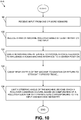
FIG. 9 , aDSSI method 70A, implemented in one embodiment by theDSSI module 70, comprises applying a control equation to a non-linear set of curves that are proportional to machine speed to generate a dynamic steering input, the dynamic steering input comprising a dynamic counter-steer component (94), and providing the dynamic counter-steer component to a steering angle set point calculation (96). The counter-steer component causes a brief counter-steer (e.g., single step torque) response to a prior steering movement of the machine. TheDSSI method 70A corresponds to theDSSI functionality 42 ofFIG. 5 . - Having described certain embodiments of a rollover risk reduction system, it should be appreciated within the context of the present disclosure that one embodiment of a rollover risk reduction method, denoted as
method 64A (e.g., as implemented at least in part by the rolloverrisk reduction software 64 along withmodules FIG. 6 ) and illustrated inFIG. 10 , comprises receiving input from one or more sensors (98) and reducing a risk of machine rollover (100) based at least in part on the input. To achieve reducing a risk of machine rollover (100), one embodiment of the rolloverrisk reduction method 64A usesARC 26 andSOA functionality 34 by: biasing a human-machine-interface to provide a force feedback to influence a human-machine-interface to a center position (102); causing rear wheels of the machine to maintain or return to straight forward travel (104); and limiting a steering angle of the machine, beyond which a rollover condition occurs, based on computation of a rollover equation with parameters corresponding to the input and machine geometry (106). Note that in some embodiments, the DSSI functionality 42 (FIG. 5 ) may be added, on any combination of ARC, SOA, and DSSI functionality may be implemented. The causing of the rear wheels to maintain or return to a straight forward travel may be achieved via theARC module 66, executed by theprocessor 52, feeding input (e.g., steering angle set-point) to theactuator 80 of the steering valve, which in turn fluidly communicates with the hydraulic circuit of the steering system (e.g., cylinders of the rear wheels, hydraulic pump, etc.) to cause the alignment of the rear wheels. - Any process descriptions or blocks in flow diagrams should be understood as representing modules, segments, or portions of code which include one or more executable instructions for implementing specific logical functions or steps in the process, and alternate implementations are included within the scope of the embodiments in which functions may be executed out of order from that shown or discussed, including substantially concurrently or in reverse order, depending on the functionality involved, as would be understood by those reasonably skilled in the art of the present disclosure. In some embodiments, steps may be omitted or added.
- In this description, references to "one embodiment", "an embodiment", or "embodiments" mean that the feature or features being referred to are included in at least one embodiment of the technology. Separate references to "one embodiment", "an embodiment", or "embodiments" in this description do not necessarily refer to the same embodiment and are also not mutually exclusive unless so stated and/or except as will be readily apparent to those skilled in the art from the description. For example, a feature, structure, act, etc. described in one embodiment may also be included in other embodiments, but is not necessarily included. Thus, the present technology can include a variety of combinations and/or integrations of the embodiments described herein. Although the control systems and methods have been described with reference to the example embodiments illustrated in the attached drawing figures, it is noted that equivalents may be employed and substitutions made herein without departing from the scope of the disclosure as protected by the following claims.
Claims (20)
- A steering system for a machine, the steering system comprising:
a steer-by-wire system configured to provide rear wheel steering, the steer-by-wire system comprising:a human-machine-interface (HMI) configured to provide a force feedback to the HMI that influences the HMI to a center position;plural sensors; andone or more controllers configured by executable code to receive input from one or more of the plural sensors and reduce a risk of rollover by:causing rear wheels of the machine to maintain or return to straight forward travel in conjunction with the force feedback; andlimiting a steering angle of the machine, beyond which a rollover condition occurs, based on computation of a rollover equation with parameters corresponding to the input and a machine geometry. - The steering system of claim 1, wherein the plural sensors include an inertial sensor, and wherein the one or more controllers are further configured to provide a steering command based on the machine exceeding a threshold rollover angle based on input from the inertial sensor.
- The steering system of claim 2, wherein the one or more controllers are configured to provide the steering command by applying a control equation to a non-linear set of curves that are proportional to machine speed to generate a dynamic steering input, the dynamic steering input comprising a counter-steer component provided to a steering angle set-point calculation.
- The steering system of claim 3, wherein the counter-steer component corresponds to a single step torque response.
- The steering system of claim 3, wherein the control equation comprises a derivative with temporary lag mathematical equation.
- The steering system of claim 1, wherein the HMI comprises a steering control for the machine that is configured to be directly manipulated by an operator.
- The steering system of claim 1, wherein the force feedback is experienced by an operator in contact with the HMI based on cooperation between the HMI and a biasing device and a torque set-point received by the one or more controllers.
- The steering system of claim 7, wherein the force feedback increases force as a function of speed of the machine.
- The steering system of claim 7, wherein the biasing device comprises a spring, a resilient device, or an electromagnetic motor.
- The steering system of claim 1, wherein the one or more controllers are configured to cause the rear wheels to maintain or return to straight forward travel by:receiving a steering angle command from the HMI based on operator input;generating a steering angle reference value based on the steering angle command; andproviding a final steering angle set-point constrained by a maximum steering angle corresponding to mechanical function of the steering system.
- The steering system of claim 1, wherein the one or more controllers are configured to limit the steering angle of the machine based on:computing a square value of ground speed; andcomputing a maximum allowed steering angle according to the rollover equation based on the square value of the ground speed, a length of a rear axle of the machine, and a height of center of mass of the machine, the maximum allowed steering angle corresponding to a maximum radius at a given speed without having a rollover condition.
- The steering system of claim 11, wherein the rollover equation consists of r = 2 * (h/(d*g))*v2, where r equals a rollover curvature radius from the center of mass of the machine, h equals the height of the machine at the center of mass, d equals the rear axle length or distance, g equals earth gravity, and v equals velocity or the ground speed of the machine.
- The steering system of claim 11, wherein the one or more controllers are configured to limit a steering angle reference value corresponding to a steering command received from the HMI using the maximum allowed steering angle.
- The steering system of claim 11, wherein the one or more controllers are configured to limit the maximum allowed steering angle to within boundaries of a maximum mechanical limit of steering.
- A rear wheel steering method for a machine, the steering method comprising:receiving input from one or more sensors; andreducing a risk of machine rollover by:biasing a human-machine-interface (HMI) to provide a force feedback to influence the HMI to a center position;causing rear wheels of the machine to maintain or return to straight forward travel in conjunction with the force feedback; andlimiting a steering angle of the machine, beyond which a rollover condition occurs, based on computation of a rollover equation with parameters corresponding to the input and a machine geometry.
- The steering method of claim 15, further comprising providing a steering command based on the machine exceeding a threshold rollover angle, wherein providing the steering command comprises applying a control equation to a non-linear set of curves that are proportional to machine speed to generate a dynamic steering input, the dynamic steering input comprising a counter-steer component provided to a steering angle set-point calculation to cause a counter-steer to a prior steering movement of the machine.
- The steering method of claim 15, wherein the causing further comprises:receiving a steering angle command;generating a steering angle reference value based on the steering angle command; andproviding a final steering angle set-point constrained by a maximum steering angle corresponding to mechanical function of a steering system.
- The steering method of claim 15, wherein limiting further comprises:computing a square value of ground speed of the machine; andcomputing a maximum allowed steering angle according to the rollover equation based on the square value of the ground speed, a length of a rear axle of the machine, and a height at center of mass of the machine, the maximum allowed steering angle corresponding to a maximum radius at a given speed without having a rollover condition.
- A non-transitory, computer readable storage medium comprising instructions that, when executed by one or more processors, causes the one or more processors to reduce a risk of rollover in a rear wheel steering machine by:receiving input from one or more sensors;biasing a human-machine-interface (HMI) to provide a force feedback to influence the HMI to a center position;causing rear wheels of the machine to maintain or return to straight forward travel in conjunction with the force feedback; andlimiting a steering angle of the machine, beyond which a rollover condition occurs, based on computation of a rollover equation with parameters corresponding to the input and a machine geometry.
- The non-transitory, computer readable storage medium of claim 19, further comprising instructions that, when executed by the one or more processors, causes the one or more processors to reduce a risk of rollover in the rear wheel steering machine by providing a steering command based on the machine exceeding a threshold rollover angle, wherein providing the steering command comprises applying a control equation to a non-linear set of curves that are proportional to machine speed to generate a dynamic steering input, the dynamic steering input comprising a counter-steer component provided to a steering angle set-point calculation to cause a counter-steer to a prior steering movement of the machine.
Applications Claiming Priority (1)
| Application Number | Priority Date | Filing Date | Title |
|---|---|---|---|
| US201862721100P | 2018-08-22 | 2018-08-22 |
Publications (2)
| Publication Number | Publication Date |
|---|---|
| EP3613652A1 true EP3613652A1 (en) | 2020-02-26 |
| EP3613652B1 EP3613652B1 (en) | 2021-12-29 |
Family
ID=67539184
Family Applications (1)
| Application Number | Title | Priority Date | Filing Date |
|---|---|---|---|
| EP19188887.4A Active EP3613652B1 (en) | 2018-08-22 | 2019-07-29 | Anti-rollover for harvesters with electronic steering |
Country Status (3)
| Country | Link |
|---|---|
| US (1) | US11458955B2 (en) |
| EP (1) | EP3613652B1 (en) |
| BR (1) | BR102019017304A2 (en) |
Cited By (4)
| Publication number | Priority date | Publication date | Assignee | Title |
|---|---|---|---|---|
| CN114932950A (en) * | 2022-04-29 | 2022-08-23 | 东风汽车有限公司东风日产乘用车公司 | Method for calculating feedforward steering wheel angle and vehicle |
| US11458955B2 (en) * | 2018-08-22 | 2022-10-04 | Agco Corporation | Anti-rollover for harvesters with electronic steering |
| EP4116114A1 (en) | 2021-07-07 | 2023-01-11 | AGCO International GmbH | System and method for automatic detection of dual wheels |
| EP4197866A1 (en) * | 2021-12-16 | 2023-06-21 | TOYOTA MATERIAL HANDLING MANUFACTURING ITALY S.p.A | Stability control of a tugger train |
Families Citing this family (2)
| Publication number | Priority date | Publication date | Assignee | Title |
|---|---|---|---|---|
| US20200086911A1 (en) * | 2018-09-14 | 2020-03-19 | Caterpillar Inc. | Machine steering angle control system |
| US11541862B2 (en) | 2020-08-27 | 2023-01-03 | Deere & Company | Operator selectable steering mode with variable torque feedback and system thereof |
Citations (2)
| Publication number | Priority date | Publication date | Assignee | Title |
|---|---|---|---|---|
| US20120029771A1 (en) * | 2010-07-30 | 2012-02-02 | Ryan Patrick Mackin | Steering control from scanned wheel information |
| DE102017011302A1 (en) * | 2017-02-16 | 2018-08-16 | Shimadzu Corporation | FORKLIFT |
Family Cites Families (25)
| Publication number | Priority date | Publication date | Assignee | Title |
|---|---|---|---|---|
| US5386365A (en) * | 1991-03-22 | 1995-01-31 | Mazda Motor Corporation | Rear wheel steering system for vehicle |
| US6373465B2 (en) | 1998-11-10 | 2002-04-16 | Lord Corporation | Magnetically-controllable, semi-active haptic interface system and apparatus |
| US6453226B1 (en) * | 2001-01-25 | 2002-09-17 | Delphi Technologies, Inc. | Integrated control of active tire steer and brakes |
| JP2007532371A (en) * | 2004-03-23 | 2007-11-15 | ケルシ・ヘイズ、カムパニ | Method and apparatus for reducing vehicle rollover |
| DE602006014553D1 (en) * | 2006-11-08 | 2010-07-08 | Ford Global Tech Llc | Anti-roll control and reduction of tipping over by steering operation |
| US8560157B2 (en) * | 2007-09-19 | 2013-10-15 | Topcon Positioning Systems, Inc. | Partial manual control state for automated vehicle navigation system |
| CN101332833A (en) * | 2008-07-24 | 2008-12-31 | 江苏大学 | Vehicle electric power-assisted steering system containing special operation condition and control method thereof |
| US8275516B2 (en) * | 2009-07-21 | 2012-09-25 | Trimble Navigation Limited | Agricultural vehicle autopilot rollover risk assessment system |
| JP5539749B2 (en) | 2010-02-15 | 2014-07-02 | ヤンマー株式会社 | Steer-by-wire combine |
| JP5807778B2 (en) * | 2011-09-15 | 2015-11-10 | 株式会社ジェイテクト | Steering device for cargo handling vehicle |
| KR101447811B1 (en) * | 2013-04-05 | 2014-10-13 | 현대중공업 주식회사 | Rollover protection control system and control method for forklift with speed and steering sensors |
| US20140343697A1 (en) | 2013-05-17 | 2014-11-20 | Caterpillar Inc. | Selectable Operating Modes for Machine Operator Input Devices |
| CN105209324B (en) | 2013-05-20 | 2018-05-25 | 罗伯特·博世有限公司 | Rear-axle steering controls |
| ITMO20130156A1 (en) * | 2013-05-30 | 2014-11-30 | Cnh Italia Spa | ANTI-TILTING SYSTEM. |
| US9266552B2 (en) * | 2013-08-05 | 2016-02-23 | Rene Guerster | Steering system for wheeled land vehicle |
| BR102013023161B1 (en) | 2013-09-10 | 2021-04-27 | Agco Do Brasil Soluções Agrícolas Ltda. | STABILITY CONTROL SYSTEM FOR AN AGRICULTURAL MACHINE |
| ES2871903T3 (en) | 2014-01-02 | 2021-11-02 | Michael R Schramm | Rollover prevention device |
| US10392007B1 (en) * | 2015-03-26 | 2019-08-27 | Hydro-Gear Limited Partnership | Stability control system |
| DE102017200144B4 (en) * | 2016-01-22 | 2019-05-02 | Ford Global Technologies, Llc | Fallback mode of operation for a method of operating a motor vehicle having an active anti-roll bar and active steering |
| KR101857035B1 (en) * | 2016-04-26 | 2018-05-15 | 현대자동차주식회사 | Vehicle rollover sensing system by driving information optimizing |
| CN106585625B (en) | 2016-12-30 | 2023-05-23 | 南京航空航天大学 | Four-wheel steering vehicle rollover prevention system and control method thereof |
| IT201700090841A1 (en) | 2017-08-04 | 2019-02-04 | Ognibene Power Spa | SELF-PROPELLED VEHICLE EQUIPPED WITH A LIFTING UNIT |
| CN108045368A (en) * | 2018-01-04 | 2018-05-18 | 济南大学 | A kind of anti-rollover detection device for being used to harvest railcar body balance |
| CN110789523A (en) * | 2018-08-01 | 2020-02-14 | 上海汽车集团股份有限公司 | Trajectory planning method and device |
| EP3613652B1 (en) * | 2018-08-22 | 2021-12-29 | AGCO Corporation | Anti-rollover for harvesters with electronic steering |
-
2019
- 2019-07-29 EP EP19188887.4A patent/EP3613652B1/en active Active
- 2019-08-12 US US16/538,257 patent/US11458955B2/en active Active
- 2019-08-20 BR BR102019017304-1A patent/BR102019017304A2/en unknown
Patent Citations (2)
| Publication number | Priority date | Publication date | Assignee | Title |
|---|---|---|---|---|
| US20120029771A1 (en) * | 2010-07-30 | 2012-02-02 | Ryan Patrick Mackin | Steering control from scanned wheel information |
| DE102017011302A1 (en) * | 2017-02-16 | 2018-08-16 | Shimadzu Corporation | FORKLIFT |
Cited By (5)
| Publication number | Priority date | Publication date | Assignee | Title |
|---|---|---|---|---|
| US11458955B2 (en) * | 2018-08-22 | 2022-10-04 | Agco Corporation | Anti-rollover for harvesters with electronic steering |
| EP4116114A1 (en) | 2021-07-07 | 2023-01-11 | AGCO International GmbH | System and method for automatic detection of dual wheels |
| EP4197866A1 (en) * | 2021-12-16 | 2023-06-21 | TOYOTA MATERIAL HANDLING MANUFACTURING ITALY S.p.A | Stability control of a tugger train |
| CN114932950A (en) * | 2022-04-29 | 2022-08-23 | 东风汽车有限公司东风日产乘用车公司 | Method for calculating feedforward steering wheel angle and vehicle |
| CN114932950B (en) * | 2022-04-29 | 2023-09-12 | 东风汽车有限公司东风日产乘用车公司 | Method for calculating feed-forward steering wheel angle and vehicle |
Also Published As
| Publication number | Publication date |
|---|---|
| EP3613652B1 (en) | 2021-12-29 |
| US20200062241A1 (en) | 2020-02-27 |
| BR102019017304A2 (en) | 2020-03-03 |
| US11458955B2 (en) | 2022-10-04 |
Similar Documents
| Publication | Publication Date | Title |
|---|---|---|
| EP3613652B1 (en) | Anti-rollover for harvesters with electronic steering | |
| US9669866B2 (en) | Steering intention determination device, vehicle control device, steering assist device, and steering assist system | |
| US10906581B2 (en) | Rack-limiting condition detection and the corresponding steering wheel torque feedback for steer by wire steering systems | |
| US9821842B2 (en) | Rear wheel steering system and control method thereof | |
| US11377140B2 (en) | Notification for rack limiting conditions for steer by wire steering systems | |
| CN107943060B (en) | Autopilot, method for guiding a vehicle along a tracking line, and computer-readable medium | |
| WO2014109151A1 (en) | Steering control device | |
| JP2008254630A (en) | Turning action control device, automobile, and turning action control method | |
| KR102277285B1 (en) | Apparatus for controlling rear wheel steering and method thereof | |
| JP6074976B2 (en) | Lane maintenance support device | |
| JP2018103713A (en) | Vehicle travel control device and automatic operation control method | |
| JP6089117B2 (en) | Power steering system control method for a vehicle having two steering axles | |
| US11447175B2 (en) | Steer ratio synchronization for steer-by-wire systems | |
| JP6007521B2 (en) | Lane maintenance support device | |
| KR20120047108A (en) | Control method for power streering handle system | |
| JP5347499B2 (en) | Vehicle control apparatus and vehicle control method | |
| JP5321107B2 (en) | Turning behavior control device and turning behavior control method | |
| SE541114C2 (en) | A method for steering assistance and a steering assist system | |
| JP5776837B2 (en) | Vehicle steering control device and vehicle steering control method | |
| JP2006069497A (en) | Steering device | |
| JP4539244B2 (en) | Front and rear wheel steering control device | |
| KR101619646B1 (en) | Lead steer control method of active front steering system | |
| JP4120488B2 (en) | Vehicle steering control device | |
| US11858574B2 (en) | Steering control device and steering control method | |
| KR20230106400A (en) | Steering system and control method therefor |
Legal Events
| Date | Code | Title | Description |
|---|---|---|---|
| PUAI | Public reference made under article 153(3) epc to a published international application that has entered the european phase |
Free format text: ORIGINAL CODE: 0009012 |
|
| STAA | Information on the status of an ep patent application or granted ep patent |
Free format text: STATUS: THE APPLICATION HAS BEEN PUBLISHED |
|
| AK | Designated contracting states |
Kind code of ref document: A1 Designated state(s): AL AT BE BG CH CY CZ DE DK EE ES FI FR GB GR HR HU IE IS IT LI LT LU LV MC MK MT NL NO PL PT RO RS SE SI SK SM TR |
|
| AX | Request for extension of the european patent |
Extension state: BA ME |
|
| STAA | Information on the status of an ep patent application or granted ep patent |
Free format text: STATUS: REQUEST FOR EXAMINATION WAS MADE |
|
| 17P | Request for examination filed |
Effective date: 20200826 |
|
| RBV | Designated contracting states (corrected) |
Designated state(s): AL AT BE BG CH CY CZ DE DK EE ES FI FR GB GR HR HU IE IS IT LI LT LU LV MC MK MT NL NO PL PT RO RS SE SI SK SM TR |
|
| GRAP | Despatch of communication of intention to grant a patent |
Free format text: ORIGINAL CODE: EPIDOSNIGR1 |
|
| STAA | Information on the status of an ep patent application or granted ep patent |
Free format text: STATUS: GRANT OF PATENT IS INTENDED |
|
| RIC1 | Information provided on ipc code assigned before grant |
Ipc: B62D 6/00 20060101AFI20210719BHEP Ipc: A01D 41/127 20060101ALI20210719BHEP |
|
| INTG | Intention to grant announced |
Effective date: 20210805 |
|
| GRAS | Grant fee paid |
Free format text: ORIGINAL CODE: EPIDOSNIGR3 |
|
| GRAA | (expected) grant |
Free format text: ORIGINAL CODE: 0009210 |
|
| STAA | Information on the status of an ep patent application or granted ep patent |
Free format text: STATUS: THE PATENT HAS BEEN GRANTED |
|
| AK | Designated contracting states |
Kind code of ref document: B1 Designated state(s): AL AT BE BG CH CY CZ DE DK EE ES FI FR GB GR HR HU IE IS IT LI LT LU LV MC MK MT NL NO PL PT RO RS SE SI SK SM TR |
|
| REG | Reference to a national code |
Ref country code: GB Ref legal event code: FG4D |
|
| REG | Reference to a national code |
Ref country code: CH Ref legal event code: EP |
|
| REG | Reference to a national code |
Ref country code: AT Ref legal event code: REF Ref document number: 1458485 Country of ref document: AT Kind code of ref document: T Effective date: 20220115 |
|
| REG | Reference to a national code |
Ref country code: IE Ref legal event code: FG4D |
|
| REG | Reference to a national code |
Ref country code: DE Ref legal event code: R096 Ref document number: 602019010391 Country of ref document: DE |
|
| REG | Reference to a national code |
Ref country code: LT Ref legal event code: MG9D |
|
| PG25 | Lapsed in a contracting state [announced via postgrant information from national office to epo] |
Ref country code: RS Free format text: LAPSE BECAUSE OF FAILURE TO SUBMIT A TRANSLATION OF THE DESCRIPTION OR TO PAY THE FEE WITHIN THE PRESCRIBED TIME-LIMIT Effective date: 20211229 Ref country code: LT Free format text: LAPSE BECAUSE OF FAILURE TO SUBMIT A TRANSLATION OF THE DESCRIPTION OR TO PAY THE FEE WITHIN THE PRESCRIBED TIME-LIMIT Effective date: 20211229 Ref country code: FI Free format text: LAPSE BECAUSE OF FAILURE TO SUBMIT A TRANSLATION OF THE DESCRIPTION OR TO PAY THE FEE WITHIN THE PRESCRIBED TIME-LIMIT Effective date: 20211229 Ref country code: BG Free format text: LAPSE BECAUSE OF FAILURE TO SUBMIT A TRANSLATION OF THE DESCRIPTION OR TO PAY THE FEE WITHIN THE PRESCRIBED TIME-LIMIT Effective date: 20220329 |
|
| REG | Reference to a national code |
Ref country code: NL Ref legal event code: MP Effective date: 20211229 |
|
| REG | Reference to a national code |
Ref country code: AT Ref legal event code: MK05 Ref document number: 1458485 Country of ref document: AT Kind code of ref document: T Effective date: 20211229 |
|
| PG25 | Lapsed in a contracting state [announced via postgrant information from national office to epo] |
Ref country code: SE Free format text: LAPSE BECAUSE OF FAILURE TO SUBMIT A TRANSLATION OF THE DESCRIPTION OR TO PAY THE FEE WITHIN THE PRESCRIBED TIME-LIMIT Effective date: 20211229 Ref country code: NO Free format text: LAPSE BECAUSE OF FAILURE TO SUBMIT A TRANSLATION OF THE DESCRIPTION OR TO PAY THE FEE WITHIN THE PRESCRIBED TIME-LIMIT Effective date: 20220329 Ref country code: LV Free format text: LAPSE BECAUSE OF FAILURE TO SUBMIT A TRANSLATION OF THE DESCRIPTION OR TO PAY THE FEE WITHIN THE PRESCRIBED TIME-LIMIT Effective date: 20211229 Ref country code: HR Free format text: LAPSE BECAUSE OF FAILURE TO SUBMIT A TRANSLATION OF THE DESCRIPTION OR TO PAY THE FEE WITHIN THE PRESCRIBED TIME-LIMIT Effective date: 20211229 Ref country code: GR Free format text: LAPSE BECAUSE OF FAILURE TO SUBMIT A TRANSLATION OF THE DESCRIPTION OR TO PAY THE FEE WITHIN THE PRESCRIBED TIME-LIMIT Effective date: 20220330 |
|
| PG25 | Lapsed in a contracting state [announced via postgrant information from national office to epo] |
Ref country code: NL Free format text: LAPSE BECAUSE OF FAILURE TO SUBMIT A TRANSLATION OF THE DESCRIPTION OR TO PAY THE FEE WITHIN THE PRESCRIBED TIME-LIMIT Effective date: 20211229 |
|
| PG25 | Lapsed in a contracting state [announced via postgrant information from national office to epo] |
Ref country code: SM Free format text: LAPSE BECAUSE OF FAILURE TO SUBMIT A TRANSLATION OF THE DESCRIPTION OR TO PAY THE FEE WITHIN THE PRESCRIBED TIME-LIMIT Effective date: 20211229 Ref country code: SK Free format text: LAPSE BECAUSE OF FAILURE TO SUBMIT A TRANSLATION OF THE DESCRIPTION OR TO PAY THE FEE WITHIN THE PRESCRIBED TIME-LIMIT Effective date: 20211229 Ref country code: RO Free format text: LAPSE BECAUSE OF FAILURE TO SUBMIT A TRANSLATION OF THE DESCRIPTION OR TO PAY THE FEE WITHIN THE PRESCRIBED TIME-LIMIT Effective date: 20211229 Ref country code: PT Free format text: LAPSE BECAUSE OF FAILURE TO SUBMIT A TRANSLATION OF THE DESCRIPTION OR TO PAY THE FEE WITHIN THE PRESCRIBED TIME-LIMIT Effective date: 20220429 Ref country code: ES Free format text: LAPSE BECAUSE OF FAILURE TO SUBMIT A TRANSLATION OF THE DESCRIPTION OR TO PAY THE FEE WITHIN THE PRESCRIBED TIME-LIMIT Effective date: 20211229 Ref country code: EE Free format text: LAPSE BECAUSE OF FAILURE TO SUBMIT A TRANSLATION OF THE DESCRIPTION OR TO PAY THE FEE WITHIN THE PRESCRIBED TIME-LIMIT Effective date: 20211229 Ref country code: CZ Free format text: LAPSE BECAUSE OF FAILURE TO SUBMIT A TRANSLATION OF THE DESCRIPTION OR TO PAY THE FEE WITHIN THE PRESCRIBED TIME-LIMIT Effective date: 20211229 |
|
| PG25 | Lapsed in a contracting state [announced via postgrant information from national office to epo] |
Ref country code: PL Free format text: LAPSE BECAUSE OF FAILURE TO SUBMIT A TRANSLATION OF THE DESCRIPTION OR TO PAY THE FEE WITHIN THE PRESCRIBED TIME-LIMIT Effective date: 20211229 Ref country code: AT Free format text: LAPSE BECAUSE OF FAILURE TO SUBMIT A TRANSLATION OF THE DESCRIPTION OR TO PAY THE FEE WITHIN THE PRESCRIBED TIME-LIMIT Effective date: 20211229 |
|
| PG25 | Lapsed in a contracting state [announced via postgrant information from national office to epo] |
Ref country code: IS Free format text: LAPSE BECAUSE OF FAILURE TO SUBMIT A TRANSLATION OF THE DESCRIPTION OR TO PAY THE FEE WITHIN THE PRESCRIBED TIME-LIMIT Effective date: 20220429 |
|
| REG | Reference to a national code |
Ref country code: DE Ref legal event code: R097 Ref document number: 602019010391 Country of ref document: DE |
|
| PG25 | Lapsed in a contracting state [announced via postgrant information from national office to epo] |
Ref country code: DK Free format text: LAPSE BECAUSE OF FAILURE TO SUBMIT A TRANSLATION OF THE DESCRIPTION OR TO PAY THE FEE WITHIN THE PRESCRIBED TIME-LIMIT Effective date: 20211229 Ref country code: AL Free format text: LAPSE BECAUSE OF FAILURE TO SUBMIT A TRANSLATION OF THE DESCRIPTION OR TO PAY THE FEE WITHIN THE PRESCRIBED TIME-LIMIT Effective date: 20211229 |
|
| PLBE | No opposition filed within time limit |
Free format text: ORIGINAL CODE: 0009261 |
|
| STAA | Information on the status of an ep patent application or granted ep patent |
Free format text: STATUS: NO OPPOSITION FILED WITHIN TIME LIMIT |
|
| 26N | No opposition filed |
Effective date: 20220930 |
|
| PG25 | Lapsed in a contracting state [announced via postgrant information from national office to epo] |
Ref country code: SI Free format text: LAPSE BECAUSE OF FAILURE TO SUBMIT A TRANSLATION OF THE DESCRIPTION OR TO PAY THE FEE WITHIN THE PRESCRIBED TIME-LIMIT Effective date: 20211229 Ref country code: MC Free format text: LAPSE BECAUSE OF FAILURE TO SUBMIT A TRANSLATION OF THE DESCRIPTION OR TO PAY THE FEE WITHIN THE PRESCRIBED TIME-LIMIT Effective date: 20211229 |
|
| REG | Reference to a national code |
Ref country code: CH Ref legal event code: PL |
|
| REG | Reference to a national code |
Ref country code: BE Ref legal event code: MM Effective date: 20220731 |
|
| PG25 | Lapsed in a contracting state [announced via postgrant information from national office to epo] |
Ref country code: LU Free format text: LAPSE BECAUSE OF NON-PAYMENT OF DUE FEES Effective date: 20220729 Ref country code: LI Free format text: LAPSE BECAUSE OF NON-PAYMENT OF DUE FEES Effective date: 20220731 Ref country code: CH Free format text: LAPSE BECAUSE OF NON-PAYMENT OF DUE FEES Effective date: 20220731 |
|
| PG25 | Lapsed in a contracting state [announced via postgrant information from national office to epo] |
Ref country code: IT Free format text: LAPSE BECAUSE OF FAILURE TO SUBMIT A TRANSLATION OF THE DESCRIPTION OR TO PAY THE FEE WITHIN THE PRESCRIBED TIME-LIMIT Effective date: 20211229 Ref country code: BE Free format text: LAPSE BECAUSE OF NON-PAYMENT OF DUE FEES Effective date: 20220731 |
|
| P01 | Opt-out of the competence of the unified patent court (upc) registered |
Effective date: 20230518 |
|
| PG25 | Lapsed in a contracting state [announced via postgrant information from national office to epo] |
Ref country code: IE Free format text: LAPSE BECAUSE OF NON-PAYMENT OF DUE FEES Effective date: 20220729 |
|
| PGFP | Annual fee paid to national office [announced via postgrant information from national office to epo] |
Ref country code: GB Payment date: 20230721 Year of fee payment: 5 |
|
| PGFP | Annual fee paid to national office [announced via postgrant information from national office to epo] |
Ref country code: FR Payment date: 20230726 Year of fee payment: 5 Ref country code: DE Payment date: 20230719 Year of fee payment: 5 |
|
| PG25 | Lapsed in a contracting state [announced via postgrant information from national office to epo] |
Ref country code: HU Free format text: LAPSE BECAUSE OF FAILURE TO SUBMIT A TRANSLATION OF THE DESCRIPTION OR TO PAY THE FEE WITHIN THE PRESCRIBED TIME-LIMIT; INVALID AB INITIO Effective date: 20190729 |
|
| PG25 | Lapsed in a contracting state [announced via postgrant information from national office to epo] |
Ref country code: MK Free format text: LAPSE BECAUSE OF FAILURE TO SUBMIT A TRANSLATION OF THE DESCRIPTION OR TO PAY THE FEE WITHIN THE PRESCRIBED TIME-LIMIT Effective date: 20211229 Ref country code: CY Free format text: LAPSE BECAUSE OF FAILURE TO SUBMIT A TRANSLATION OF THE DESCRIPTION OR TO PAY THE FEE WITHIN THE PRESCRIBED TIME-LIMIT Effective date: 20211229 |