EP3613470B1 - Multi-functional fire engine using liquid nitrogen as jet power and mixing jetting gun - Google Patents
Multi-functional fire engine using liquid nitrogen as jet power and mixing jetting gun Download PDFInfo
- Publication number
- EP3613470B1 EP3613470B1 EP18891661.3A EP18891661A EP3613470B1 EP 3613470 B1 EP3613470 B1 EP 3613470B1 EP 18891661 A EP18891661 A EP 18891661A EP 3613470 B1 EP3613470 B1 EP 3613470B1
- Authority
- EP
- European Patent Office
- Prior art keywords
- liquid nitrogen
- pipeline
- water
- spray gun
- input end
- Prior art date
- Legal status (The legal status is an assumption and is not a legal conclusion. Google has not performed a legal analysis and makes no representation as to the accuracy of the status listed.)
- Active
Links
Images


Classifications
-
- A—HUMAN NECESSITIES
- A62—LIFE-SAVING; FIRE-FIGHTING
- A62C—FIRE-FIGHTING
- A62C27/00—Fire-fighting land vehicles
-
- A—HUMAN NECESSITIES
- A62—LIFE-SAVING; FIRE-FIGHTING
- A62C—FIRE-FIGHTING
- A62C31/00—Delivery of fire-extinguishing material
-
- A—HUMAN NECESSITIES
- A62—LIFE-SAVING; FIRE-FIGHTING
- A62C—FIRE-FIGHTING
- A62C31/00—Delivery of fire-extinguishing material
- A62C31/02—Nozzles specially adapted for fire-extinguishing
-
- A—HUMAN NECESSITIES
- A62—LIFE-SAVING; FIRE-FIGHTING
- A62C—FIRE-FIGHTING
- A62C31/00—Delivery of fire-extinguishing material
- A62C31/02—Nozzles specially adapted for fire-extinguishing
- A62C31/05—Nozzles specially adapted for fire-extinguishing with two or more outlets
- A62C31/07—Nozzles specially adapted for fire-extinguishing with two or more outlets for different media
-
- A—HUMAN NECESSITIES
- A62—LIFE-SAVING; FIRE-FIGHTING
- A62C—FIRE-FIGHTING
- A62C5/00—Making of fire-extinguishing materials immediately before use
- A62C5/008—Making of fire-extinguishing materials immediately before use for producing other mixtures of different gases or vapours, water and chemicals, e.g. water and wetting agents, water and gases
-
- A—HUMAN NECESSITIES
- A62—LIFE-SAVING; FIRE-FIGHTING
- A62C—FIRE-FIGHTING
- A62C99/00—Subject matter not provided for in other groups of this subclass
- A62C99/0009—Methods of extinguishing or preventing the spread of fire by cooling down or suffocating the flames
- A62C99/0072—Methods of extinguishing or preventing the spread of fire by cooling down or suffocating the flames using sprayed or atomised water
-
- F—MECHANICAL ENGINEERING; LIGHTING; HEATING; WEAPONS; BLASTING
- F17—STORING OR DISTRIBUTING GASES OR LIQUIDS
- F17C—VESSELS FOR CONTAINING OR STORING COMPRESSED, LIQUEFIED OR SOLIDIFIED GASES; FIXED-CAPACITY GAS-HOLDERS; FILLING VESSELS WITH, OR DISCHARGING FROM VESSELS, COMPRESSED, LIQUEFIED, OR SOLIDIFIED GASES
- F17C3/00—Vessels not under pressure
-
- A—HUMAN NECESSITIES
- A62—LIFE-SAVING; FIRE-FIGHTING
- A62C—FIRE-FIGHTING
- A62C31/00—Delivery of fire-extinguishing material
- A62C31/005—Delivery of fire-extinguishing material using nozzles
-
- A—HUMAN NECESSITIES
- A62—LIFE-SAVING; FIRE-FIGHTING
- A62C—FIRE-FIGHTING
- A62C99/00—Subject matter not provided for in other groups of this subclass
- A62C99/0009—Methods of extinguishing or preventing the spread of fire by cooling down or suffocating the flames
- A62C99/0018—Methods of extinguishing or preventing the spread of fire by cooling down or suffocating the flames using gases or vapours that do not support combustion, e.g. steam, carbon dioxide
-
- F—MECHANICAL ENGINEERING; LIGHTING; HEATING; WEAPONS; BLASTING
- F17—STORING OR DISTRIBUTING GASES OR LIQUIDS
- F17C—VESSELS FOR CONTAINING OR STORING COMPRESSED, LIQUEFIED OR SOLIDIFIED GASES; FIXED-CAPACITY GAS-HOLDERS; FILLING VESSELS WITH, OR DISCHARGING FROM VESSELS, COMPRESSED, LIQUEFIED, OR SOLIDIFIED GASES
- F17C13/00—Details of vessels or of the filling or discharging of vessels
- F17C13/04—Arrangement or mounting of valves
-
- F—MECHANICAL ENGINEERING; LIGHTING; HEATING; WEAPONS; BLASTING
- F17—STORING OR DISTRIBUTING GASES OR LIQUIDS
- F17C—VESSELS FOR CONTAINING OR STORING COMPRESSED, LIQUEFIED OR SOLIDIFIED GASES; FIXED-CAPACITY GAS-HOLDERS; FILLING VESSELS WITH, OR DISCHARGING FROM VESSELS, COMPRESSED, LIQUEFIED, OR SOLIDIFIED GASES
- F17C13/00—Details of vessels or of the filling or discharging of vessels
- F17C13/08—Mounting arrangements for vessels
- F17C13/083—Mounting arrangements for vessels for medium-sized mobile storage vessels, e.g. tank vehicles or railway tank vehicles
-
- F—MECHANICAL ENGINEERING; LIGHTING; HEATING; WEAPONS; BLASTING
- F17—STORING OR DISTRIBUTING GASES OR LIQUIDS
- F17C—VESSELS FOR CONTAINING OR STORING COMPRESSED, LIQUEFIED OR SOLIDIFIED GASES; FIXED-CAPACITY GAS-HOLDERS; FILLING VESSELS WITH, OR DISCHARGING FROM VESSELS, COMPRESSED, LIQUEFIED, OR SOLIDIFIED GASES
- F17C2201/00—Vessel construction, in particular geometry, arrangement or size
- F17C2201/01—Shape
- F17C2201/0104—Shape cylindrical
- F17C2201/0109—Shape cylindrical with exteriorly curved end-piece
-
- F—MECHANICAL ENGINEERING; LIGHTING; HEATING; WEAPONS; BLASTING
- F17—STORING OR DISTRIBUTING GASES OR LIQUIDS
- F17C—VESSELS FOR CONTAINING OR STORING COMPRESSED, LIQUEFIED OR SOLIDIFIED GASES; FIXED-CAPACITY GAS-HOLDERS; FILLING VESSELS WITH, OR DISCHARGING FROM VESSELS, COMPRESSED, LIQUEFIED, OR SOLIDIFIED GASES
- F17C2201/00—Vessel construction, in particular geometry, arrangement or size
- F17C2201/03—Orientation
- F17C2201/035—Orientation with substantially horizontal main axis
-
- F—MECHANICAL ENGINEERING; LIGHTING; HEATING; WEAPONS; BLASTING
- F17—STORING OR DISTRIBUTING GASES OR LIQUIDS
- F17C—VESSELS FOR CONTAINING OR STORING COMPRESSED, LIQUEFIED OR SOLIDIFIED GASES; FIXED-CAPACITY GAS-HOLDERS; FILLING VESSELS WITH, OR DISCHARGING FROM VESSELS, COMPRESSED, LIQUEFIED, OR SOLIDIFIED GASES
- F17C2201/00—Vessel construction, in particular geometry, arrangement or size
- F17C2201/05—Size
- F17C2201/054—Size medium (>1 m3)
-
- F—MECHANICAL ENGINEERING; LIGHTING; HEATING; WEAPONS; BLASTING
- F17—STORING OR DISTRIBUTING GASES OR LIQUIDS
- F17C—VESSELS FOR CONTAINING OR STORING COMPRESSED, LIQUEFIED OR SOLIDIFIED GASES; FIXED-CAPACITY GAS-HOLDERS; FILLING VESSELS WITH, OR DISCHARGING FROM VESSELS, COMPRESSED, LIQUEFIED, OR SOLIDIFIED GASES
- F17C2203/00—Vessel construction, in particular walls or details thereof
- F17C2203/03—Thermal insulations
- F17C2203/0304—Thermal insulations by solid means
- F17C2203/0308—Radiation shield
- F17C2203/032—Multi-sheet layers
-
- F—MECHANICAL ENGINEERING; LIGHTING; HEATING; WEAPONS; BLASTING
- F17—STORING OR DISTRIBUTING GASES OR LIQUIDS
- F17C—VESSELS FOR CONTAINING OR STORING COMPRESSED, LIQUEFIED OR SOLIDIFIED GASES; FIXED-CAPACITY GAS-HOLDERS; FILLING VESSELS WITH, OR DISCHARGING FROM VESSELS, COMPRESSED, LIQUEFIED, OR SOLIDIFIED GASES
- F17C2203/00—Vessel construction, in particular walls or details thereof
- F17C2203/03—Thermal insulations
- F17C2203/0391—Thermal insulations by vacuum
-
- F—MECHANICAL ENGINEERING; LIGHTING; HEATING; WEAPONS; BLASTING
- F17—STORING OR DISTRIBUTING GASES OR LIQUIDS
- F17C—VESSELS FOR CONTAINING OR STORING COMPRESSED, LIQUEFIED OR SOLIDIFIED GASES; FIXED-CAPACITY GAS-HOLDERS; FILLING VESSELS WITH, OR DISCHARGING FROM VESSELS, COMPRESSED, LIQUEFIED, OR SOLIDIFIED GASES
- F17C2203/00—Vessel construction, in particular walls or details thereof
- F17C2203/06—Materials for walls or layers thereof; Properties or structures of walls or their materials
- F17C2203/0602—Wall structures; Special features thereof
- F17C2203/0604—Liners
-
- F—MECHANICAL ENGINEERING; LIGHTING; HEATING; WEAPONS; BLASTING
- F17—STORING OR DISTRIBUTING GASES OR LIQUIDS
- F17C—VESSELS FOR CONTAINING OR STORING COMPRESSED, LIQUEFIED OR SOLIDIFIED GASES; FIXED-CAPACITY GAS-HOLDERS; FILLING VESSELS WITH, OR DISCHARGING FROM VESSELS, COMPRESSED, LIQUEFIED, OR SOLIDIFIED GASES
- F17C2203/00—Vessel construction, in particular walls or details thereof
- F17C2203/06—Materials for walls or layers thereof; Properties or structures of walls or their materials
- F17C2203/0602—Wall structures; Special features thereof
- F17C2203/0612—Wall structures
- F17C2203/0626—Multiple walls
- F17C2203/0629—Two walls
-
- F—MECHANICAL ENGINEERING; LIGHTING; HEATING; WEAPONS; BLASTING
- F17—STORING OR DISTRIBUTING GASES OR LIQUIDS
- F17C—VESSELS FOR CONTAINING OR STORING COMPRESSED, LIQUEFIED OR SOLIDIFIED GASES; FIXED-CAPACITY GAS-HOLDERS; FILLING VESSELS WITH, OR DISCHARGING FROM VESSELS, COMPRESSED, LIQUEFIED, OR SOLIDIFIED GASES
- F17C2205/00—Vessel construction, in particular mounting arrangements, attachments or identifications means
- F17C2205/03—Fluid connections, filters, valves, closure means or other attachments
- F17C2205/0302—Fittings, valves, filters, or components in connection with the gas storage device
- F17C2205/0323—Valves
- F17C2205/0326—Valves electrically actuated
-
- F—MECHANICAL ENGINEERING; LIGHTING; HEATING; WEAPONS; BLASTING
- F17—STORING OR DISTRIBUTING GASES OR LIQUIDS
- F17C—VESSELS FOR CONTAINING OR STORING COMPRESSED, LIQUEFIED OR SOLIDIFIED GASES; FIXED-CAPACITY GAS-HOLDERS; FILLING VESSELS WITH, OR DISCHARGING FROM VESSELS, COMPRESSED, LIQUEFIED, OR SOLIDIFIED GASES
- F17C2205/00—Vessel construction, in particular mounting arrangements, attachments or identifications means
- F17C2205/03—Fluid connections, filters, valves, closure means or other attachments
- F17C2205/0302—Fittings, valves, filters, or components in connection with the gas storage device
- F17C2205/0323—Valves
- F17C2205/0332—Safety valves or pressure relief valves
-
- F—MECHANICAL ENGINEERING; LIGHTING; HEATING; WEAPONS; BLASTING
- F17—STORING OR DISTRIBUTING GASES OR LIQUIDS
- F17C—VESSELS FOR CONTAINING OR STORING COMPRESSED, LIQUEFIED OR SOLIDIFIED GASES; FIXED-CAPACITY GAS-HOLDERS; FILLING VESSELS WITH, OR DISCHARGING FROM VESSELS, COMPRESSED, LIQUEFIED, OR SOLIDIFIED GASES
- F17C2205/00—Vessel construction, in particular mounting arrangements, attachments or identifications means
- F17C2205/03—Fluid connections, filters, valves, closure means or other attachments
- F17C2205/0302—Fittings, valves, filters, or components in connection with the gas storage device
- F17C2205/0352—Pipes
-
- F—MECHANICAL ENGINEERING; LIGHTING; HEATING; WEAPONS; BLASTING
- F17—STORING OR DISTRIBUTING GASES OR LIQUIDS
- F17C—VESSELS FOR CONTAINING OR STORING COMPRESSED, LIQUEFIED OR SOLIDIFIED GASES; FIXED-CAPACITY GAS-HOLDERS; FILLING VESSELS WITH, OR DISCHARGING FROM VESSELS, COMPRESSED, LIQUEFIED, OR SOLIDIFIED GASES
- F17C2205/00—Vessel construction, in particular mounting arrangements, attachments or identifications means
- F17C2205/03—Fluid connections, filters, valves, closure means or other attachments
- F17C2205/0302—Fittings, valves, filters, or components in connection with the gas storage device
- F17C2205/0352—Pipes
- F17C2205/0364—Pipes flexible or articulated, e.g. a hose
-
- F—MECHANICAL ENGINEERING; LIGHTING; HEATING; WEAPONS; BLASTING
- F17—STORING OR DISTRIBUTING GASES OR LIQUIDS
- F17C—VESSELS FOR CONTAINING OR STORING COMPRESSED, LIQUEFIED OR SOLIDIFIED GASES; FIXED-CAPACITY GAS-HOLDERS; FILLING VESSELS WITH, OR DISCHARGING FROM VESSELS, COMPRESSED, LIQUEFIED, OR SOLIDIFIED GASES
- F17C2205/00—Vessel construction, in particular mounting arrangements, attachments or identifications means
- F17C2205/03—Fluid connections, filters, valves, closure means or other attachments
- F17C2205/0388—Arrangement of valves, regulators, filters
-
- F—MECHANICAL ENGINEERING; LIGHTING; HEATING; WEAPONS; BLASTING
- F17—STORING OR DISTRIBUTING GASES OR LIQUIDS
- F17C—VESSELS FOR CONTAINING OR STORING COMPRESSED, LIQUEFIED OR SOLIDIFIED GASES; FIXED-CAPACITY GAS-HOLDERS; FILLING VESSELS WITH, OR DISCHARGING FROM VESSELS, COMPRESSED, LIQUEFIED, OR SOLIDIFIED GASES
- F17C2221/00—Handled fluid, in particular type of fluid
- F17C2221/01—Pure fluids
- F17C2221/014—Nitrogen
-
- F—MECHANICAL ENGINEERING; LIGHTING; HEATING; WEAPONS; BLASTING
- F17—STORING OR DISTRIBUTING GASES OR LIQUIDS
- F17C—VESSELS FOR CONTAINING OR STORING COMPRESSED, LIQUEFIED OR SOLIDIFIED GASES; FIXED-CAPACITY GAS-HOLDERS; FILLING VESSELS WITH, OR DISCHARGING FROM VESSELS, COMPRESSED, LIQUEFIED, OR SOLIDIFIED GASES
- F17C2223/00—Handled fluid before transfer, i.e. state of fluid when stored in the vessel or before transfer from the vessel
- F17C2223/01—Handled fluid before transfer, i.e. state of fluid when stored in the vessel or before transfer from the vessel characterised by the phase
- F17C2223/0146—Two-phase
- F17C2223/0153—Liquefied gas, e.g. LPG, GPL
-
- F—MECHANICAL ENGINEERING; LIGHTING; HEATING; WEAPONS; BLASTING
- F17—STORING OR DISTRIBUTING GASES OR LIQUIDS
- F17C—VESSELS FOR CONTAINING OR STORING COMPRESSED, LIQUEFIED OR SOLIDIFIED GASES; FIXED-CAPACITY GAS-HOLDERS; FILLING VESSELS WITH, OR DISCHARGING FROM VESSELS, COMPRESSED, LIQUEFIED, OR SOLIDIFIED GASES
- F17C2225/00—Handled fluid after transfer, i.e. state of fluid after transfer from the vessel
- F17C2225/01—Handled fluid after transfer, i.e. state of fluid after transfer from the vessel characterised by the phase
- F17C2225/0107—Single phase
- F17C2225/0123—Single phase gaseous, e.g. CNG, GNC
-
- F—MECHANICAL ENGINEERING; LIGHTING; HEATING; WEAPONS; BLASTING
- F17—STORING OR DISTRIBUTING GASES OR LIQUIDS
- F17C—VESSELS FOR CONTAINING OR STORING COMPRESSED, LIQUEFIED OR SOLIDIFIED GASES; FIXED-CAPACITY GAS-HOLDERS; FILLING VESSELS WITH, OR DISCHARGING FROM VESSELS, COMPRESSED, LIQUEFIED, OR SOLIDIFIED GASES
- F17C2227/00—Transfer of fluids, i.e. method or means for transferring the fluid; Heat exchange with the fluid
- F17C2227/01—Propulsion of the fluid
- F17C2227/0128—Propulsion of the fluid with pumps or compressors
- F17C2227/0135—Pumps
-
- F—MECHANICAL ENGINEERING; LIGHTING; HEATING; WEAPONS; BLASTING
- F17—STORING OR DISTRIBUTING GASES OR LIQUIDS
- F17C—VESSELS FOR CONTAINING OR STORING COMPRESSED, LIQUEFIED OR SOLIDIFIED GASES; FIXED-CAPACITY GAS-HOLDERS; FILLING VESSELS WITH, OR DISCHARGING FROM VESSELS, COMPRESSED, LIQUEFIED, OR SOLIDIFIED GASES
- F17C2227/00—Transfer of fluids, i.e. method or means for transferring the fluid; Heat exchange with the fluid
- F17C2227/03—Heat exchange with the fluid
- F17C2227/0302—Heat exchange with the fluid by heating
- F17C2227/0309—Heat exchange with the fluid by heating using another fluid
- F17C2227/0311—Air heating
-
- F—MECHANICAL ENGINEERING; LIGHTING; HEATING; WEAPONS; BLASTING
- F17—STORING OR DISTRIBUTING GASES OR LIQUIDS
- F17C—VESSELS FOR CONTAINING OR STORING COMPRESSED, LIQUEFIED OR SOLIDIFIED GASES; FIXED-CAPACITY GAS-HOLDERS; FILLING VESSELS WITH, OR DISCHARGING FROM VESSELS, COMPRESSED, LIQUEFIED, OR SOLIDIFIED GASES
- F17C2227/00—Transfer of fluids, i.e. method or means for transferring the fluid; Heat exchange with the fluid
- F17C2227/03—Heat exchange with the fluid
- F17C2227/0367—Localisation of heat exchange
- F17C2227/0388—Localisation of heat exchange separate
- F17C2227/039—Localisation of heat exchange separate on the pipes
-
- F—MECHANICAL ENGINEERING; LIGHTING; HEATING; WEAPONS; BLASTING
- F17—STORING OR DISTRIBUTING GASES OR LIQUIDS
- F17C—VESSELS FOR CONTAINING OR STORING COMPRESSED, LIQUEFIED OR SOLIDIFIED GASES; FIXED-CAPACITY GAS-HOLDERS; FILLING VESSELS WITH, OR DISCHARGING FROM VESSELS, COMPRESSED, LIQUEFIED, OR SOLIDIFIED GASES
- F17C2227/00—Transfer of fluids, i.e. method or means for transferring the fluid; Heat exchange with the fluid
- F17C2227/03—Heat exchange with the fluid
- F17C2227/0367—Localisation of heat exchange
- F17C2227/0397—Localisation of heat exchange characterised by fins
-
- F—MECHANICAL ENGINEERING; LIGHTING; HEATING; WEAPONS; BLASTING
- F17—STORING OR DISTRIBUTING GASES OR LIQUIDS
- F17C—VESSELS FOR CONTAINING OR STORING COMPRESSED, LIQUEFIED OR SOLIDIFIED GASES; FIXED-CAPACITY GAS-HOLDERS; FILLING VESSELS WITH, OR DISCHARGING FROM VESSELS, COMPRESSED, LIQUEFIED, OR SOLIDIFIED GASES
- F17C2250/00—Accessories; Control means; Indicating, measuring or monitoring of parameters
- F17C2250/04—Indicating or measuring of parameters as input values
- F17C2250/0404—Parameters indicated or measured
- F17C2250/043—Pressure
-
- F—MECHANICAL ENGINEERING; LIGHTING; HEATING; WEAPONS; BLASTING
- F17—STORING OR DISTRIBUTING GASES OR LIQUIDS
- F17C—VESSELS FOR CONTAINING OR STORING COMPRESSED, LIQUEFIED OR SOLIDIFIED GASES; FIXED-CAPACITY GAS-HOLDERS; FILLING VESSELS WITH, OR DISCHARGING FROM VESSELS, COMPRESSED, LIQUEFIED, OR SOLIDIFIED GASES
- F17C2265/00—Effects achieved by gas storage or gas handling
- F17C2265/02—Mixing fluids
- F17C2265/025—Mixing fluids different fluids
-
- F—MECHANICAL ENGINEERING; LIGHTING; HEATING; WEAPONS; BLASTING
- F17—STORING OR DISTRIBUTING GASES OR LIQUIDS
- F17C—VESSELS FOR CONTAINING OR STORING COMPRESSED, LIQUEFIED OR SOLIDIFIED GASES; FIXED-CAPACITY GAS-HOLDERS; FILLING VESSELS WITH, OR DISCHARGING FROM VESSELS, COMPRESSED, LIQUEFIED, OR SOLIDIFIED GASES
- F17C2270/00—Applications
- F17C2270/01—Applications for fluid transport or storage
- F17C2270/0165—Applications for fluid transport or storage on the road
- F17C2270/0168—Applications for fluid transport or storage on the road by vehicles
-
- F—MECHANICAL ENGINEERING; LIGHTING; HEATING; WEAPONS; BLASTING
- F17—STORING OR DISTRIBUTING GASES OR LIQUIDS
- F17C—VESSELS FOR CONTAINING OR STORING COMPRESSED, LIQUEFIED OR SOLIDIFIED GASES; FIXED-CAPACITY GAS-HOLDERS; FILLING VESSELS WITH, OR DISCHARGING FROM VESSELS, COMPRESSED, LIQUEFIED, OR SOLIDIFIED GASES
- F17C2270/00—Applications
- F17C2270/01—Applications for fluid transport or storage
- F17C2270/0165—Applications for fluid transport or storage on the road
- F17C2270/0168—Applications for fluid transport or storage on the road by vehicles
- F17C2270/0171—Trucks
-
- F—MECHANICAL ENGINEERING; LIGHTING; HEATING; WEAPONS; BLASTING
- F17—STORING OR DISTRIBUTING GASES OR LIQUIDS
- F17C—VESSELS FOR CONTAINING OR STORING COMPRESSED, LIQUEFIED OR SOLIDIFIED GASES; FIXED-CAPACITY GAS-HOLDERS; FILLING VESSELS WITH, OR DISCHARGING FROM VESSELS, COMPRESSED, LIQUEFIED, OR SOLIDIFIED GASES
- F17C2270/00—Applications
- F17C2270/07—Applications for household use
- F17C2270/0754—Fire extinguishers
Definitions
- the disclosure relates to fire-fighting technology, and more particularly to a multifunctional fire engine which uses liquid nitrogen as a jet power.
- Liquid nitrogen is also a substance that converts energy by phase change. Liquid nitrogen is boiled and gasified at -195.8°C under normal pressure. More than 800 liters of pure nitrogen can be produced per 1 kg of liquid nitrogen, and the process also absorbs 198 kJ of latent heat of vaporization. When liquid nitrogen and water are mixed in the fire tube, the liquid nitrogen rapidly absorbs the heat of the water and rapidly vaporizes, and its volume rapidly increases by several hundred times, generating a strong thrust in the pipeline. This phenomenon is equivalent to the power of "igniting propellant", which can promote high-speed injection of "gas-water” mixed fluid. The exit velocity at the exit is much higher than the exit rate of the water jet of a conventional fire engine.
- a large flow of water or water-based fire extinguishing agent is sprayed into a jet in the form of fine water mist or ultra-fine water mist.
- This "gas-water” mixed fluid not only enlarges the contact area of the fire extinguishing agent with the flame, but also expands the contact area between the decontaminant and the toxic gas. It overcomes the shortcoming that the water jet sprayed by the conventional fire engine quickly falls to the ground, resulting in the loss of water.
- the "gas-water” mixed fluid has a longer range than the water mist jet emitted by the conventional fire engine, and a larger kinetic energy that penetrates into the flame, which can greatly improve the efficiency of firefighting and rescue. As a result, a fire engine with liquid nitrogen as the injection power can be developed.
- Chinese Patent Publication No. 03133926.3 discloses a liquid nitrogen fire engine and a liquid nitrogen spray gun.
- the main principle is that the liquid nitrogen pump is driven by the automobile gearbox to pressurize the liquid nitrogen stored in the liquid nitrogen storage tank, and then the liquid nitrogen is input into the liquid nitrogen spray gun to extinguish the fire.
- This application does not teach the technical problem of using a phase change produced when liquid nitrogen is mixed with water to promote high velocity injection of the mixed fluid.
- Chinese Patent Application No. 201710225285.2 discloses a fire cannon with liquid nitrogen power.
- the liquid nitrogen entering the fire cannon is first vaporized to generate nitrogen by heat absorption, and the resulting supersonic nitrogen fluid then collides with the water fluid entering the fire cannon to yield a mixed fluid.
- the application does not describe the release of large pressure energy at the moment when the liquid nitrogen and water are mixed, and there is no solution to the problem that the volume of the liquid nitrogen sharply increases in the fire gun to generate an "air plug".
- Chinese Patent Application No. 200910035880.5 and 201210517766.8 disclose a technical solution for producing a fine water mist or foam beads by collision of a high velocity gas jet with water or a foam fire extinguishing liquid. The application is silent to the pressure energy produced by the instantaneous phase change of liquid nitrogen when the liquid nitrogen is mixed with a water fluid.
- CN106823220 discloses a mixed spray gun for a fire extinguishing system using nitrogen as power source.
- the disclosure provides a multifunctional fire engine with liquid nitrogen as a jet power.
- the fire engine can store liquid nitrogen, mix the liquid nitrogen and water to produce large kinetic energy, and can also use the large kinetic energy to transform water, water-based fire extinguishing agent or detergent into a high-speed atomized mixed fluid, thus improving the efficiency of firefighting and rescue.
- a multifunctional fire engine with liquid nitrogen as a jet power comprising a vehicle frame, a liquid nitrogen storage tank, a liquid nitrogen conveying pipeline, a gasification device, a plurality of electric valves, a water pipe adapter, a liquid nitrogen spray gun, and a mixed spray gun.
- the liquid nitrogen storage tank is disposed on the vehicle frame.
- the liquid nitrogen conveying pipeline comprises at least a first pipeline, a second pipeline, and a third pipeline.
- the first pipeline connects a lower part of the liquid nitrogen storage tank, the gasification device, and an upper part of the liquid nitrogen storage tank sequentially in that order;
- the second pipeline connects the liquid nitrogen storage tank, an input end of the liquid nitrogen spray gun, and a first input end of the mixed spray gun sequentially in that order.
- the third pipeline is provided with a safety valve 4 and a relief valve 10, and the external liquid nitrogen is input to the liquid nitrogen storage tank 2 via the third pipeline.
- the mixed spray gun comprises a first input end, a second input end, a liquid nitrogen nozzle and a spray pipe
- the spray pipe comprises a contraction section, an expansion section, and an acceleration section which are connected to one another in that order.
- the inner diameter of the contraction section decreases, and the inner diameter of the expansion section increases.
- the inner diameter of the acceleration section is constant and equal to the outlet diameter of the expansion section.
- the liquid nitrogen nozzle communicates with the first input end and disposed on the axial line of the contraction section (8-1); the outlet of the liquid nitrogen nozzle is coaxial with the outlet of the contraction section (8-1).
- An inlet of the second input end is connected to the water pipe adapter and an outlet of the second input end communicates with the contraction section; the plurality of electric valves is disposed on the liquid nitrogen conveying pipeline and a water delivery pipeline connected to the water pipe adapter.
- a mixed spray gun comprises a first input end, a second input end, a liquid nitrogen nozzle and a spray pipe, and the spray pipe comprises a contraction section, an expansion section, and an acceleration section which are connected to one another in that order.
- the inner diameter of the contraction section decreases, and the inner diameter of the expansion section increases.
- the inner diameter of the acceleration section is constant and equal to the outlet diameter of the expansion section.
- the liquid nitrogen nozzle communicates with the first input end and disposed on the axial line of the contraction section; the outlet of the liquid nitrogen nozzle is coaxial with the outlet of the contraction section.
- An inlet of the second input end is connected to a water source and an outlet of the second input end communicates with the contraction section.
- the gasification device comprises a gasification tube and a plurality of heat dissipating fins; the gasification tube is connected to the first pipeline, and the heat dissipating fins are radially disposed on the outer wall of the gasification tube.
- the liquid nitrogen storage tank comprises a housing, a liner, and a gap between the housing and the liner; the liner is disposed in the housing.
- the gap is dried and evacuated to 0.001 to 0.005 Pa, and the outer surface of the liner is provided with a heat insulating material comprising a zirconia foil layer.
- liquid nitrogen, water, a water-based fire extinguishing agent and a chemical decontaminant are mixed in a liquid nitrogen spray gun.
- the liquid nitrogen is gasified, and the phase change expands the volume thereof hundreds of times, and the powerful thrust is produced to atomize and spray the water, water fire extinguishing agent or chemical decontaminant with high velocity and large flow rate, thus greatly improving the efficiency of firefighting and emergency rescue, and reducing the water consumption.
- the liquid nitrogen absorbs heat in the gasification device to increase the internal pressure of the liquid nitrogen storage tank, and in the firefighting process, a small amount of liquid nitrogen is guided to the gasification device for gasification.
- the pressure in the liquid nitrogen storage tank can rise to 1.2 to 1.6 megapascal, and the liquid nitrogen is continuously and steadily supplied to the fire gun at this pressure.
- (3) The thermal conductivity of zirconia foil in the liquid nitrogen storage tank is low ((1.01 ⁇ 10 -4 W / m•K), and the reflectance of the zirconia foil to the long wave, medium wave and infrared is as high as 85% or higher.
- the thermal insulation performance is superior to the traditional ultra-thin glass wool insulation material without heat reflection performance; the intermediate layer between the housing and the liner is dried to remove water, and then pumped to a high vacuum state using a high vacuum pump. This state prevents heat convection exchange inside and outside the tank. Under natural conditions, the annual loss rate of liquid nitrogen in the liquid nitrogen storage tank is less than 1/4 of the total reserves.
- a multifunctional fire engine with liquid nitrogen as an injection power comprises a vehicle frame 1, a liquid nitrogen storage tank 2, a liquid nitrogen conveying pipeline 9, a gasification device 15, a rotatable support 7, a folding crane 3, a water delivery pipeline 11, a water pipe adapter 12, a mixed spray gun 8, a liquid nitrogen spray gun 13, and a plurality of electric valves.
- the liquid nitrogen storage tank 2 is disposed on the vehicle frame.
- the liquid nitrogen storage tank 2 comprises a steel housing 2-1, a liner 2-2, and a heat insulating material 2-3.
- the liner 2-2 is of a steel material and disposed in the housing 2-1. There is a gap between the housing and the liner.
- the heat insulating material 2-3 is wound around the outer surface of the liner.
- the insulating material 2-3 of the zirconia foil layer is wound on the outer surface of the liner 2-2.
- the zirconia foil has a low thermal conductivity (1.01 ⁇ 10 -4 W/m•K), a reflectivity of more than 85% for long-wave, medium-wave and infrared, and its thermal insulation performance is better than glass wool which has no thermal reflectivity.
- the intermediate layer between the housing 2-1 and the liner 2-2 is completely dried to remove water, and evacuated to 0.001 to 0.005 Pa.
- the heat convection exchange inside and outside the tank is blocked by the vacuum layer.
- the zirconia aluminum foil with excellent heat insulation and reflectivity properties can prevent the heat radiation exchange inside and outside the tank.
- the tank has excellent thermal insulation properties.
- the liquid nitrogen storage tank 2 is provided with a safety valve 4, a level gauge 5, a pressure sensor 6, a relief valve 10, and a liquid nitrogen conveying pipeline 9.
- the safety valve 4 is disposed above the liquid nitrogen storage tank 2 for releasing the pressure in the tank when the air pressure in the liquid nitrogen storage tank 2 is too high, so that the pressure value in the tank is maintained between 1.2 and 1.6 megapascal.
- the level gauge 5 is disposed in the middle and upper part of the liquid nitrogen storage tank 2 for indicating the amount of the liquid nitrogen remaining in the liquid nitrogen storage tank 2.
- the pressure sensor 6 is disposed above the liquid nitrogen storage tank 2 for measuring the gas pressure in the liquid nitrogen storage tank 2.
- the relief valve 10 is disposed above the liquid nitrogen storage tank 2 for maintaining the pressure of the liquid nitrogen in the tank not more than 0.8 megapascal. When the pressure in the tank is greater than the value, the relief valve is opened to release a portion of low temperature nitrogen in the tank to reduce the pressure in the tank and achieve a long-time cryogenic storage of liquid nitrogen.
- the liquid nitrogen conveying pipeline 9 is provided with three paths:
- the gasification device 15 comprises a gasification tube 15-1 and a plurality of heat dissipation fins 15-2. Both ends of the gasification tube 15-1 are seamlessly connected to the first pipeline, and the heat dissipating fins 15-2 are radially disposed on the outer wall of the gasification tube 15-1.
- the heat dissipating fins 15-2 increase the surface area and improve the gasification efficiency of the liquid nitrogen.
- the rotatable support 7 is disposed on the vehicle frame 1, and the folding crane 3 is fixed on the rotatable support and is capable of rotation on the horizontal surface of the rotatable support 7.
- the folding arm 3 is disposed above the liquid nitrogen storage tank 2.
- the folding arm 3 comprises a plurality of mutually connected folding arms that are folded when not in use to save the space, and the folding arms are extended to a desired length in use.
- the water source is a pure water having a pressure of 0.8 to 1.0 megapascal, or comprises a water-based fire extinguishing agent with 3% F-500 and 1 to 3% of FireAde2000, a 6% aqueous film-forming foam extinguishing agent, 1% Class A foam fire extinguishing agent, or a chemical decontaminant.
- the mixed spray gun 8 is disposed on the front end of the folding crane 3, and can approach to the fire source closely by horizontal rotation and pitch injection in the three-dimensional space of the folding crane 3.
- the mixed spray gun 8 comprises a first input end, a second input end, a liquid nitrogen nozzle 8-4, and a spray pipe.
- the spray pipe comprises a contraction section 8-1, an expansion section 8-2, and an acceleration section 8-3 along a direction from the contraction section to the acceleration section.
- the inner diameter of the contraction section 8-1 gradually decreases, and the inner diameter of the expansion section 8-2 gradually increases.
- the inner diameter of the acceleration section 8-3 is constant and equal to the outlet diameter of the expansion section 8-2.
- the liquid nitrogen nozzle communicates with the first input end and disposed on the axial line of the contraction section 8-1; the outlet of the liquid nitrogen nozzle 8-4 is coaxial with the outlet of the contraction section 8-1.
- An inlet of the second input end is connected to the water pipe adapter 12 and an outlet of the second input end communicates with the contraction section 8-1.
- the method of mixing the liquid nitrogen with water to produce a "gas-water” mixed fluid is implemented as follows: the water pipe adapter 12 provides water having a pressure of 0.8 to 1.0 megapascal, water-based fire extinguishing agent or chemical decontaminating agent.
- the liquid enters the mixed spray gun 8 and flows through the contraction section 8-1 and the expansion section 8-2, and is ejected from the acceleration section 8-3.
- the liquid nitrogen from the liquid nitrogen storage tank 2 having a pressure of 1.2 to 1.6 megapascal is injected through the liquid nitrogen nozzle 8-4 and mixed with the water, water fire extinguishing agent or chemical decontamination solution in the contraction section 8-1 of the mixed spray gun 8 to form a liquid nitrogen jet.
- the liquid nitrogen jet collides with the water fluid and ruptures to yield a plurality of liquid nitrogen beads.
- the liquid nitrogen beads absorb heat, vaporize and expand in the expansion section 8-2, and flow quickly.
- the compressed nitrogen gas continues to expand under the pressure difference between the inside and the outside of the mixed spray gun 8.
- the mixed fluid is accelerated again, and the pressure of the nitrogen at the outlet of the mixed spray gun 8 is reduced to be equal to the external atmospheric pressure.
- the water, the water-based fire extinguishing agent or the chemical decontaminant obtains sufficient energy of the compressed nitrogen gas to be ejected from the mixed spray gun 8 in the form of an atomized fluid with a high speed.
- the mixed spray gun 8 when the water flow rate of the mixed spray gun is 60 L/s, the flow rate of the liquid nitrogen controlled by the electric valve 14-4 to be 3 kg/s, the mixed spray gun 8 emits an ultra-fine water mist jet having an average particle diameter of about 200 ⁇ m and a jet velocity of 80 to 100 m/s. This ultra-fine water mist jet is used for rapid smoke and temperature cooling and suppressing deflagration and detonation.
- the electric valve 14-4 controls the flow rate of the liquid nitrogen to 2 kg/s
- the mixed spray gun 8 When the electric valve 14-4 controls the flow rate of the liquid nitrogen to 2 kg/s, the mixed spray gun 8 emits a high-temperature spray of a water-based fire extinguishing agent having an average particle diameter of about 400 to 500 ⁇ m, and the outlet flow rate can reach 60 to 80 m/s. Changing the flow rate of the liquid nitrogen can eject different particle diameters of water mists sprayed from the mixed spray gun 8.
- the liquid nitrogen spray gun 13 is disposed on each side of the vehicle frame 1.
- the inlet end of the liquid nitrogen spray gun 13 is connected to the liquid nitrogen storage tank 2 through the second pipeline having a length of 50 to 80 m.
- the liquid nitrogen sprayed from the liquid nitrogen spray gun 13 is used to extinguish a fire that cannot be extinguished by water.
- the electric valve is disposed on the liquid nitrogen conveying pipeline 9 and the water delivery pipeline:
- the first electric valve 14-1 and the pressure sensor 6 control the flow rate of the liquid nitrogen entering the liquid nitrogenizing device 15; the second electric valve 14-2 controls the flow rate of the liquid nitrogen sprayed from the liquid nitrogen spray gun 13 to be between 1 and 4 kg/s; the third electric valve 14-3 controls the pressure of water, water-based fire extinguishing agent or chemical decontaminating agent from outside to be within 0.8 to 1.0 megapascal; and the fourth electric valve 14-4 controls the flow rate of the liquid nitrogen entering the mixed spray gun 8 so that the mixing ratio of the liquid nitrogen to the water is 1: 20-40.
- Liquid nitrogen has a temperature of -196°C under normal pressure, and 1 L of liquid nitrogen can produce 696 L of pure nitrogen gas at 21°C. Specifically, closing the relief valve 10 and opening the electric valve 14-1. A portion of the liquid nitrogen from the bottom of the liquid nitrogen storage tank 2 through the first pipeline enters the gasification device 15 through the electric valve 14-1 by gravity. The liquid nitrogen absorbs external heat and is vaporized into nitrogen gas, and the pressure in the gasification device 15 rises due to the increase of the volume of nitrogen gas. Nitrogen gas is introduced into the tank from the top of the tank through the liquid nitrogen conveying pipeline to pressurize the liquid nitrogen in the tank.
- the pressure sensor 6 controls the flow rate of the liquid nitrogen into the liquid nitrogen gasifier 15 through the electric valve 14-1 to ensure that the pressure in the tank is between 1.2 and 1.6 megapascal.
- the safety valve 4 opens to release pressure, and the pressure value in the tank is kept stable.
- the pressure sensor 6 lowers the flow rate of the liquid nitrogen entering the liquid nitrogen gasifier 15 through the electric valve 14-1, or directly closes the electric valve 14-1 to restore the pressure inside the tank.
- the electric valve 14-2 that outputs liquid nitrogen is opened, the liquid nitrogen in the tank is output to the outside of the tank at a pressure of 1.2 to 1.6 megapascal.
- the electric valve 14-2 controls the flow rate of liquid nitrogen to be between 1 and 4 kg/s, which can be adjusted as needed.
- the fire engine with liquid nitrogen as the injection power comprises a vehicle frame 1, a liquid nitrogen storage tank 2, a folding crane 3, a safety valve 4, a liquid level gauge 5, a pressure sensor 6, a rotatable support 7, a mixed spray gun 8, a liquid nitrogen conveying pipeline 9, a relief valve 10, a water delivery pipeline 11, a water pipe adapter 12, a liquid nitrogen spray gun 13, a first electric valve 14-1, a second electric valve 14-2, a third electric valve 14-3, and a gasification device 15.
- the liquid nitrogen storage tank 2 is mounted on the vehicle frame 1, and the rotatable support 7 and the folding crane 3 are disposed on one side of the liquid nitrogen storage tank 2, and the water pipe adapter 12 is disposed below the rotatable support 7.
- a mixed spray gun 8 is mounted on the upper end of the folding crane 3, and the liquid nitrogen nozzle 8-4 in the mixed spray gun 8 is connected to the liquid nitrogen storage tank 2 through the liquid nitrogen conveying pipeline 9 and the electric valve 14-2.
- the water inlet end of the mixed spray gun 8 is connected to the water pipe adapter 12 through the water delivery pipeline 11 and the electric valve 14-3.
- the liquid nitrogen from the liquid nitrogen storage tank 2 having a pressure of 1.2 to 1.6 megapascal and the water or water-based fire extinguishing agent from the external water tank having a pressure of 0.8 to 1.0 megapascal enter the mixed spray gun 8 and produce a "gas-water" mixed fluid that is ejected at a rate of 60 to 80 m/s.
- the folding crane 3 is unfolded and rotated to align the mixed spray gun 8 with the fire source to extinguish the fire with a mist jet of rapid spray water or water fire extinguishing agent.
- the implementation method will be further explained by taking the fire of the petrochemical plant as an example.
- the fire engine with liquid nitrogen as the jet power is supported by a water tank fire engine.
- the position of the mixed spray gun 8 can be up to 32 meters, or the mixed spray gun 8 can be extended in a horizontal front direction to an appropriate position near the fire source.
- the third electric valve 14-3 and the fourth electric valve 14-4 are opened, and the water pipe adapter 12 inputs water containing 3% F-500 fire extinguishing agent into the mixed spray gun 8 through the water delivery pipeline 11.
- the liquid nitrogen enters the liquid nitrogen nozzle 8-4 of the mixed spray gun 8 through the liquid nitrogen conveying pipeline 9 via the fourth electric valve 14-4.
- the liquid nitrogen and the water comprising 3% F-500 fire extinguishing agent are mixed in the mixed spray gun 8 and then ejected at a high speed in the form of a misty fluid.
- the F-500 fire extinguishing agent has rapid cooling ability, which can combine with water molecules to encapsulate flammable liquid molecules to prevent it from burning, so as to quickly extinguish the flame.
- the fire engine comprises a liquid nitrogen liquid nitrogen spray gun 13 connected to the outlet of the liquid nitrogen storage tank 2 through the second electric valve 14-2 and the liquid nitrogen conveying pipeline 9.
- the liquid nitrogen conveying pipeline 9 has a length of 80 m.
- pull out the liquid nitrogen spray gun 13 shut down all doors and windows of the garment warehouse, open the second electric valve 14-2, and the firefighters wearing the positive pressure breathing apparatus take the liquid nitrogen spray gun 13 into the warehouse, or spray the liquid nitrogen fire extinguishing agent into the warehouse from the crack of the door. All the open flames and smouldering fires are extinguished in the warehouse when the oxygen content in the air drops below 10%.
- Afire engine carrying 5 tons of liquid nitrogen can extinguish a fire in a clothing warehouse with the volume of no more than 4000 m 3 .
- the liquid nitrogen enters the liquid nitrogen nozzle 8-4 of the mixed spray gun 8 via the fourth electric valve 14-4 and the liquid nitrogen conveying pipeline 9.
- the liquid nitrogen and the decontamination solution containing dissolved sodium carbonate are mixed in the mixed spray gun 8, and then sprayed at a high speed in a misty fluid and blended with the leaked chlorine gas.
- Sodium carbonate reacts with the chlorine gas to form sodium chloride to release carbon dioxide.
- the water mist absorbs the chlorine gas to form hypochlorous acid falling to the ground, so that the leaked chlorine gas is diluted.
Landscapes
- Health & Medical Sciences (AREA)
- Public Health (AREA)
- Business, Economics & Management (AREA)
- Emergency Management (AREA)
- Engineering & Computer Science (AREA)
- Mechanical Engineering (AREA)
- General Engineering & Computer Science (AREA)
- Fire-Extinguishing By Fire Departments, And Fire-Extinguishing Equipment And Control Thereof (AREA)
- Nozzles (AREA)
Description
- The disclosure relates to fire-fighting technology, and more particularly to a multifunctional fire engine which uses liquid nitrogen as a jet power.
- In Chinese National Standard
GB20128-2006 - Liquid nitrogen is also a substance that converts energy by phase change. Liquid nitrogen is boiled and gasified at -195.8°C under normal pressure. More than 800 liters of pure nitrogen can be produced per 1 kg of liquid nitrogen, and the process also absorbs 198 kJ of latent heat of vaporization. When liquid nitrogen and water are mixed in the fire tube, the liquid nitrogen rapidly absorbs the heat of the water and rapidly vaporizes, and its volume rapidly increases by several hundred times, generating a strong thrust in the pipeline. This phenomenon is equivalent to the power of "igniting propellant", which can promote high-speed injection of "gas-water" mixed fluid. The exit velocity at the exit is much higher than the exit rate of the water jet of a conventional fire engine. A large flow of water or water-based fire extinguishing agent is sprayed into a jet in the form of fine water mist or ultra-fine water mist. This "gas-water" mixed fluid not only enlarges the contact area of the fire extinguishing agent with the flame, but also expands the contact area between the decontaminant and the toxic gas. It overcomes the shortcoming that the water jet sprayed by the conventional fire engine quickly falls to the ground, resulting in the loss of water. Moreover, the "gas-water" mixed fluid has a longer range than the water mist jet emitted by the conventional fire engine, and a larger kinetic energy that penetrates into the flame, which can greatly improve the efficiency of firefighting and rescue. As a result, a fire engine with liquid nitrogen as the injection power can be developed.
-
Chinese Patent Publication No. 03133926.3 discloses a liquid nitrogen fire engine and a liquid nitrogen spray gun. The main principle is that the liquid nitrogen pump is driven by the automobile gearbox to pressurize the liquid nitrogen stored in the liquid nitrogen storage tank, and then the liquid nitrogen is input into the liquid nitrogen spray gun to extinguish the fire. This application does not teach the technical problem of using a phase change produced when liquid nitrogen is mixed with water to promote high velocity injection of the mixed fluid. -
Chinese Patent Application No. 201710225285.2 -
Chinese Patent Application No. 200910035880.5 201210517766.8 CN106823220 discloses a mixed spray gun for a fire extinguishing system using nitrogen as power source. - The disclosure provides a multifunctional fire engine with liquid nitrogen as a jet power. The fire engine can store liquid nitrogen, mix the liquid nitrogen and water to produce large kinetic energy, and can also use the large kinetic energy to transform water, water-based fire extinguishing agent or detergent into a high-speed atomized mixed fluid, thus improving the efficiency of firefighting and rescue.
- Disclosed is a multifunctional fire engine with liquid nitrogen as a jet power, comprising a vehicle frame, a liquid nitrogen storage tank, a liquid nitrogen conveying pipeline, a gasification device, a plurality of electric valves, a water pipe adapter, a liquid nitrogen spray gun, and a mixed spray gun. The liquid nitrogen storage tank is disposed on the vehicle frame.
- The liquid nitrogen conveying pipeline comprises at least a first pipeline, a second pipeline, and a third pipeline. The first pipeline connects a lower part of the liquid nitrogen storage tank, the gasification device, and an upper part of the liquid nitrogen storage tank sequentially in that order; the second pipeline connects the liquid nitrogen storage tank, an input end of the liquid nitrogen spray gun, and a first input end of the mixed spray gun sequentially in that order. The third pipeline is provided with a
safety valve 4 and arelief valve 10, and the external liquid nitrogen is input to the liquidnitrogen storage tank 2 via the third pipeline. The mixed spray gun comprises a first input end, a second input end, a liquid nitrogen nozzle and a spray pipe, and the spray pipe comprises a contraction section, an expansion section, and an acceleration section which are connected to one another in that order. Along a direction from the contraction section to the acceleration section, the inner diameter of the contraction section decreases, and the inner diameter of the expansion section increases. The inner diameter of the acceleration section is constant and equal to the outlet diameter of the expansion section. The liquid nitrogen nozzle communicates with the first input end and disposed on the axial line of the contraction section (8-1); the outlet of the liquid nitrogen nozzle is coaxial with the outlet of the contraction section (8-1). An inlet of the second input end is connected to the water pipe adapter and an outlet of the second input end communicates with the contraction section; the plurality of electric valves is disposed on the liquid nitrogen conveying pipeline and a water delivery pipeline connected to the water pipe adapter. - A mixed spray gun comprises a first input end, a second input end, a liquid nitrogen nozzle and a spray pipe, and the spray pipe comprises a contraction section, an expansion section, and an acceleration section which are connected to one another in that order. Along a direction from the contraction section to the acceleration section, the inner diameter of the contraction section decreases, and the inner diameter of the expansion section increases. The inner diameter of the acceleration section is constant and equal to the outlet diameter of the expansion section. The liquid nitrogen nozzle communicates with the first input end and disposed on the axial line of the contraction section; the outlet of the liquid nitrogen nozzle is coaxial with the outlet of the contraction section. An inlet of the second input end is connected to a water source and an outlet of the second input end communicates with the contraction section.
- The gasification device comprises a gasification tube and a plurality of heat dissipating fins; the gasification tube is connected to the first pipeline, and the heat dissipating fins are radially disposed on the outer wall of the gasification tube.
- The liquid nitrogen storage tank comprises a housing, a liner, and a gap between the housing and the liner; the liner is disposed in the housing. The gap is dried and evacuated to 0.001 to 0.005 Pa, and the outer surface of the liner is provided with a heat insulating material comprising a zirconia foil layer.
- Compared with the prior art, the disclosure has the following advantages: (1) liquid nitrogen, water, a water-based fire extinguishing agent and a chemical decontaminant are mixed in a liquid nitrogen spray gun. The liquid nitrogen is gasified, and the phase change expands the volume thereof hundreds of times, and the powerful thrust is produced to atomize and spray the water, water fire extinguishing agent or chemical decontaminant with high velocity and large flow rate, thus greatly improving the efficiency of firefighting and emergency rescue, and reducing the water consumption. (2) The liquid nitrogen absorbs heat in the gasification device to increase the internal pressure of the liquid nitrogen storage tank, and in the firefighting process, a small amount of liquid nitrogen is guided to the gasification device for gasification. The pressure in the liquid nitrogen storage tank can rise to 1.2 to 1.6 megapascal, and the liquid nitrogen is continuously and steadily supplied to the fire gun at this pressure. (3) The thermal conductivity of zirconia foil in the liquid nitrogen storage tank is low ((1.01×10⁻⁴ W / m•K), and the reflectance of the zirconia foil to the long wave, medium wave and infrared is as high as 85% or higher. The thermal insulation performance is superior to the traditional ultra-thin glass wool insulation material without heat reflection performance; the intermediate layer between the housing and the liner is dried to remove water, and then pumped to a high vacuum state using a high vacuum pump. This state prevents heat convection exchange inside and outside the tank. Under natural conditions, the annual loss rate of liquid nitrogen in the liquid nitrogen storage tank is less than 1/4 of the total reserves.
- The invention is further described below in conjunction with the drawings.
-
FIG. 1 is a schematic diagram of a liquid nitrogen fire engine as described in the disclosure. -
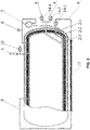
FIG. 2 is a schematic diagram of a liquid nitrogen storage tank as described in the disclosure. -
FIG. 3A is a side view of a gasification device andFIG. 3B is a cross-sectional view taken along line A-A ofFIG. 3A as described in the disclosure. -
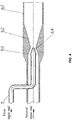
FIG. 4 is a cross-sectional view of a mixing liquid nitrogen spray gun as described in the disclosure. - In the drawings, the following reference numbers are used: 1. Vehicle frame; 2. Liquid nitrogen storage tank; 2-1. Housing; 2-2. Liner; 2-3. Heat insulating material; 3. Folding crane; 4. Safety valve; 5. Level gauge; 6. Pressure sensor; 7. Rotatable support; 8. Mixed spray gun; 8-1. Contraction section, 8-2. Expansion section; 8-3. Acceleration section; 8-4. Liquid nitrogen nozzle; 9. Liquid nitrogen conveying pipeline; 10. Relief valve; 11. Water delivery pipeline; 12. Water pipe adapter; 13. Liquid nitrogen spray gun; 14-1. First electric valve; 14-2. Second electric valve; 14-3. Third electric valve; 14-4. Fourth electric valve; 15. Gasification device; 15-1. Gasification tube; 15-2. Heat dissipating fins.
- As shown in
FIG. 1 , a multifunctional fire engine with liquid nitrogen as an injection power comprises avehicle frame 1, a liquidnitrogen storage tank 2, a liquidnitrogen conveying pipeline 9, agasification device 15, arotatable support 7, a folding crane 3, awater delivery pipeline 11, awater pipe adapter 12, a mixed spray gun 8, a liquidnitrogen spray gun 13, and a plurality of electric valves. - As shown in
FIG. 2 , the liquidnitrogen storage tank 2 is disposed on the vehicle frame. The liquidnitrogen storage tank 2 comprises a steel housing 2-1, a liner 2-2, and a heat insulating material 2-3. The liner 2-2 is of a steel material and disposed in the housing 2-1. There is a gap between the housing and the liner. The heat insulating material 2-3 is wound around the outer surface of the liner. During manufacturing the liquidnitrogen storage tank 2, the insulating material 2-3 of the zirconia foil layer is wound on the outer surface of the liner 2-2. The zirconia foil has a low thermal conductivity (1.01 × 10⁻⁴ W/m•K), a reflectivity of more than 85% for long-wave, medium-wave and infrared, and its thermal insulation performance is better than glass wool which has no thermal reflectivity. The intermediate layer between the housing 2-1 and the liner 2-2 is completely dried to remove water, and evacuated to 0.001 to 0.005 Pa. The heat convection exchange inside and outside the tank is blocked by the vacuum layer. The zirconia aluminum foil with excellent heat insulation and reflectivity properties can prevent the heat radiation exchange inside and outside the tank. Thus, the tank has excellent thermal insulation properties. - As shown in
FIG. 2 , the liquidnitrogen storage tank 2 is provided with asafety valve 4, alevel gauge 5, apressure sensor 6, arelief valve 10, and a liquidnitrogen conveying pipeline 9. - The
safety valve 4 is disposed above the liquidnitrogen storage tank 2 for releasing the pressure in the tank when the air pressure in the liquidnitrogen storage tank 2 is too high, so that the pressure value in the tank is maintained between 1.2 and 1.6 megapascal. - The
level gauge 5 is disposed in the middle and upper part of the liquidnitrogen storage tank 2 for indicating the amount of the liquid nitrogen remaining in the liquidnitrogen storage tank 2. - The
pressure sensor 6 is disposed above the liquidnitrogen storage tank 2 for measuring the gas pressure in the liquidnitrogen storage tank 2. - The
relief valve 10 is disposed above the liquidnitrogen storage tank 2 for maintaining the pressure of the liquid nitrogen in the tank not more than 0.8 megapascal. When the pressure in the tank is greater than the value, the relief valve is opened to release a portion of low temperature nitrogen in the tank to reduce the pressure in the tank and achieve a long-time cryogenic storage of liquid nitrogen. - The liquid
nitrogen conveying pipeline 9 is provided with three paths: - (1) The first pipeline starts from the bottom of the liquid
nitrogen storage tank 2, passes through thegasification device 15, and then is connected to the top of the liquidnitrogen storage tank 2. - (2) The second pipeline connects the liquid
nitrogen storage tank 2 and the input end of the liquidnitrogen spray gun 13 and the first input end of the mixed spray gun 8. - (3) The third pipeline connects the liquid
nitrogen storage tank 2 and thesafety valve 4 and therelief valve 10. - As shown in
FIG. 3 , thegasification device 15 comprises a gasification tube 15-1 and a plurality of heat dissipation fins 15-2. Both ends of the gasification tube 15-1 are seamlessly connected to the first pipeline, and the heat dissipating fins 15-2 are radially disposed on the outer wall of the gasification tube 15-1. The heat dissipating fins 15-2 increase the surface area and improve the gasification efficiency of the liquid nitrogen. - As shown in
FIG. 1 , therotatable support 7 is disposed on thevehicle frame 1, and the folding crane 3 is fixed on the rotatable support and is capable of rotation on the horizontal surface of therotatable support 7. - As shown in
FIG. 1 , the folding arm 3 is disposed above the liquidnitrogen storage tank 2. The folding arm 3 comprises a plurality of mutually connected folding arms that are folded when not in use to save the space, and the folding arms are extended to a desired length in use. - As shown in
FIG. 1 , one end of thewater delivery pipeline 11 is connected to thewater pipe adapter 12, and thewater pipe adapter 12 is connected to an external water source. The water source is a pure water having a pressure of 0.8 to 1.0 megapascal, or comprises a water-based fire extinguishing agent with 3% F-500 and 1 to 3% of FireAde2000, a 6% aqueous film-forming foam extinguishing agent, 1% Class A foam fire extinguishing agent, or a chemical decontaminant. - As shown in
FIG. 4 , the mixed spray gun 8 is disposed on the front end of the folding crane 3, and can approach to the fire source closely by horizontal rotation and pitch injection in the three-dimensional space of the folding crane 3. The mixed spray gun 8 comprises a first input end, a second input end, a liquid nitrogen nozzle 8-4, and a spray pipe. The spray pipe comprises a contraction section 8-1, an expansion section 8-2, and an acceleration section 8-3 along a direction from the contraction section to the acceleration section. - Along the direction from the contraction section to the acceleration section, the inner diameter of the contraction section 8-1 gradually decreases, and the inner diameter of the expansion section 8-2 gradually increases. The inner diameter of the acceleration section 8-3 is constant and equal to the outlet diameter of the expansion section 8-2. The liquid nitrogen nozzle communicates with the first input end and disposed on the axial line of the contraction section 8-1; the outlet of the liquid nitrogen nozzle 8-4 is coaxial with the outlet of the contraction section 8-1. An inlet of the second input end is connected to the
water pipe adapter 12 and an outlet of the second input end communicates with the contraction section 8-1. - The method of mixing the liquid nitrogen with water to produce a "gas-water" mixed fluid is implemented as follows: the
water pipe adapter 12 provides water having a pressure of 0.8 to 1.0 megapascal, water-based fire extinguishing agent or chemical decontaminating agent. The liquid enters the mixed spray gun 8 and flows through the contraction section 8-1 and the expansion section 8-2, and is ejected from the acceleration section 8-3. The liquid nitrogen from the liquidnitrogen storage tank 2 having a pressure of 1.2 to 1.6 megapascal is injected through the liquid nitrogen nozzle 8-4 and mixed with the water, water fire extinguishing agent or chemical decontamination solution in the contraction section 8-1 of the mixed spray gun 8 to form a liquid nitrogen jet. The liquid nitrogen jet collides with the water fluid and ruptures to yield a plurality of liquid nitrogen beads. The liquid nitrogen beads absorb heat, vaporize and expand in the expansion section 8-2, and flow quickly. After the "gas-water" mixed fluid enters the acceleration section 8-3, the compressed nitrogen gas continues to expand under the pressure difference between the inside and the outside of the mixed spray gun 8. The mixed fluid is accelerated again, and the pressure of the nitrogen at the outlet of the mixed spray gun 8 is reduced to be equal to the external atmospheric pressure. Thus, the water, the water-based fire extinguishing agent or the chemical decontaminant obtains sufficient energy of the compressed nitrogen gas to be ejected from the mixed spray gun 8 in the form of an atomized fluid with a high speed. For example, when the water flow rate of the mixed spray gun is 60 L/s, the flow rate of the liquid nitrogen controlled by the electric valve 14-4 to be 3 kg/s, the mixed spray gun 8 emits an ultra-fine water mist jet having an average particle diameter of about 200 µm and a jet velocity of 80 to 100 m/s. This ultra-fine water mist jet is used for rapid smoke and temperature cooling and suppressing deflagration and detonation. When the electric valve 14-4 controls the flow rate of the liquid nitrogen to 2 kg/s, the mixed spray gun 8 emits a high-temperature spray of a water-based fire extinguishing agent having an average particle diameter of about 400 to 500 µm, and the outlet flow rate can reach 60 to 80 m/s. Changing the flow rate of the liquid nitrogen can eject different particle diameters of water mists sprayed from the mixed spray gun 8. - As shown in
FIG. 1 , the liquidnitrogen spray gun 13 is disposed on each side of thevehicle frame 1. The inlet end of the liquidnitrogen spray gun 13 is connected to the liquidnitrogen storage tank 2 through the second pipeline having a length of 50 to 80 m. The liquid nitrogen sprayed from the liquidnitrogen spray gun 13 is used to extinguish a fire that cannot be extinguished by water. - The electric valve is disposed on the liquid
nitrogen conveying pipeline 9 and the water delivery pipeline: - (1) a first electric valve 14-1 disposed on the first pipeline;
- (2) a second electric valve 14-2 disposed on the liquid nitrogen conveying pipeline of the liquid
nitrogen spray gun 13; - (3) a third electric valve 14-3 disposed on the water delivery pipeline of the
water pipe adapter 12; - (4) a fourth electric valve 14-4 disposed on the liquid nitrogen conveying pipeline of the mixed spray gun 8.
- The first electric valve 14-1 and the
pressure sensor 6 control the flow rate of the liquid nitrogen entering theliquid nitrogenizing device 15; the second electric valve 14-2 controls the flow rate of the liquid nitrogen sprayed from the liquidnitrogen spray gun 13 to be between 1 and 4 kg/s; the third electric valve 14-3 controls the pressure of water, water-based fire extinguishing agent or chemical decontaminating agent from outside to be within 0.8 to 1.0 megapascal; and the fourth electric valve 14-4 controls the flow rate of the liquid nitrogen entering the mixed spray gun 8 so that the mixing ratio of the liquid nitrogen to the water is 1: 20-40. - Liquid nitrogen has a temperature of -196°C under normal pressure, and 1 L of liquid nitrogen can produce 696 L of pure nitrogen gas at 21°C. Specifically, closing the
relief valve 10 and opening the electric valve 14-1. A portion of the liquid nitrogen from the bottom of the liquidnitrogen storage tank 2 through the first pipeline enters thegasification device 15 through the electric valve 14-1 by gravity. The liquid nitrogen absorbs external heat and is vaporized into nitrogen gas, and the pressure in thegasification device 15 rises due to the increase of the volume of nitrogen gas. Nitrogen gas is introduced into the tank from the top of the tank through the liquid nitrogen conveying pipeline to pressurize the liquid nitrogen in the tank. Thepressure sensor 6 controls the flow rate of the liquid nitrogen into theliquid nitrogen gasifier 15 through the electric valve 14-1 to ensure that the pressure in the tank is between 1.2 and 1.6 megapascal. When the pressure value in the tank is higher than 1.6 megapascal, thesafety valve 4 opens to release pressure, and the pressure value in the tank is kept stable. Thepressure sensor 6 lowers the flow rate of the liquid nitrogen entering theliquid nitrogen gasifier 15 through the electric valve 14-1, or directly closes the electric valve 14-1 to restore the pressure inside the tank. When the electric valve 14-2 that outputs liquid nitrogen is opened, the liquid nitrogen in the tank is output to the outside of the tank at a pressure of 1.2 to 1.6 megapascal. The electric valve 14-2 controls the flow rate of liquid nitrogen to be between 1 and 4 kg/s, which can be adjusted as needed. - As shown in
FIG. 1 , the fire engine with liquid nitrogen as the injection power comprises avehicle frame 1, a liquidnitrogen storage tank 2, a folding crane 3, asafety valve 4, aliquid level gauge 5, apressure sensor 6, arotatable support 7, a mixed spray gun 8, a liquidnitrogen conveying pipeline 9, arelief valve 10, awater delivery pipeline 11, awater pipe adapter 12, a liquidnitrogen spray gun 13, a first electric valve 14-1, a second electric valve 14-2, a third electric valve 14-3, and agasification device 15. The liquidnitrogen storage tank 2 is mounted on thevehicle frame 1, and therotatable support 7 and the folding crane 3 are disposed on one side of the liquidnitrogen storage tank 2, and thewater pipe adapter 12 is disposed below therotatable support 7. A mixed spray gun 8 is mounted on the upper end of the folding crane 3, and the liquid nitrogen nozzle 8-4 in the mixed spray gun 8 is connected to the liquidnitrogen storage tank 2 through the liquidnitrogen conveying pipeline 9 and the electric valve 14-2. The water inlet end of the mixed spray gun 8 is connected to thewater pipe adapter 12 through thewater delivery pipeline 11 and the electric valve 14-3. Simultaneously open the second electric valve 14-2 and the third electric valve 14-3, the liquid nitrogen from the liquidnitrogen storage tank 2 having a pressure of 1.2 to 1.6 megapascal and the water or water-based fire extinguishing agent from the external water tank having a pressure of 0.8 to 1.0 megapascal enter the mixed spray gun 8 and produce a "gas-water" mixed fluid that is ejected at a rate of 60 to 80 m/s. The folding crane 3 is unfolded and rotated to align the mixed spray gun 8 with the fire source to extinguish the fire with a mist jet of rapid spray water or water fire extinguishing agent. - The implementation method will be further explained by taking the fire of the petrochemical plant as an example. The fire engine with liquid nitrogen as the jet power is supported by a water tank fire engine. When the folding crane 3 is fully opened, the position of the mixed spray gun 8 can be up to 32 meters, or the mixed spray gun 8 can be extended in a horizontal front direction to an appropriate position near the fire source. The third electric valve 14-3 and the fourth electric valve 14-4 are opened, and the
water pipe adapter 12 inputs water containing 3% F-500 fire extinguishing agent into the mixed spray gun 8 through thewater delivery pipeline 11. The liquid nitrogen enters the liquid nitrogen nozzle 8-4 of the mixed spray gun 8 through the liquidnitrogen conveying pipeline 9 via the fourth electric valve 14-4. The liquid nitrogen and the water comprising 3% F-500 fire extinguishing agent are mixed in the mixed spray gun 8 and then ejected at a high speed in the form of a misty fluid. The F-500 fire extinguishing agent has rapid cooling ability, which can combine with water molecules to encapsulate flammable liquid molecules to prevent it from burning, so as to quickly extinguish the flame. - Take the fire fighting in a clothing warehouse as an example. As shown in
FIG. 1 , the fire engine comprises a liquid nitrogen liquidnitrogen spray gun 13 connected to the outlet of the liquidnitrogen storage tank 2 through the second electric valve 14-2 and the liquidnitrogen conveying pipeline 9. The liquidnitrogen conveying pipeline 9 has a length of 80 m. In use, pull out the liquidnitrogen spray gun 13, shut down all doors and windows of the garment warehouse, open the second electric valve 14-2, and the firefighters wearing the positive pressure breathing apparatus take the liquidnitrogen spray gun 13 into the warehouse, or spray the liquid nitrogen fire extinguishing agent into the warehouse from the crack of the door. All the open flames and smouldering fires are extinguished in the warehouse when the oxygen content in the air drops below 10%. Afire engine carrying 5 tons of liquid nitrogen can extinguish a fire in a clothing warehouse with the volume of no more than 4000 m3. - In the case of the leakage of liquid chlorine, yellow-green chlorine gas is produced, and the density of the chlorine gas is 3.21 kg/m3 at normal temperature, which is close to the ground and spreads downstream with the wind. Under the support of a water tank fire engine, the fire engine in the example stays about 30 to 40 m from the liquid chlorine leakage position in the upwind or crosswind direction. The folding crane 3 is opened, and the mixed spray gun 8 is extended to face the liquid chlorine leakage position. Open the third electric valve 14-3 and the fourth electric valve 14-4, and the decontamination solution containing dissolved sodium carbonate enters the mixed spray gun 8 via the
water pipe adapter 12 and thewater delivery pipeline 11. The liquid nitrogen enters the liquid nitrogen nozzle 8-4 of the mixed spray gun 8 via the fourth electric valve 14-4 and the liquidnitrogen conveying pipeline 9. The liquid nitrogen and the decontamination solution containing dissolved sodium carbonate are mixed in the mixed spray gun 8, and then sprayed at a high speed in a misty fluid and blended with the leaked chlorine gas. Sodium carbonate reacts with the chlorine gas to form sodium chloride to release carbon dioxide. The water mist absorbs the chlorine gas to form hypochlorous acid falling to the ground, so that the leaked chlorine gas is diluted.
Claims (10)
- A multifunctional fire engine with liquid nitrogen as a jet power, comprising a vehicle frame (1), a liquid nitrogen storage tank (2), a liquid nitrogen conveying pipeline (9), a gasification device (15), a plurality of electric valves, a water pipe adapter (12), a liquid nitrogen spray gun (13), and a mixed spray gun (8); wherein:the liquid nitrogen storage tank (2) is disposed on the vehicle frame (1);the liquid nitrogen conveying pipeline (9) comprises at least a first pipeline and a second pipeline; the first pipeline connects a lower part of the liquid nitrogen storage tank (2), the gasification device (15), and an upper part of the liquid nitrogen storage tank sequentially in that order; the second pipeline connects the liquid nitrogen storage tank (2), an input end of the liquid nitrogen spray gun (13) and a first input end of the mixed spray gun (8) sequentially in that order;the mixed spray gun (8) comprises a first input end, a second input end, a liquid nitrogen nozzle (8-4), and a spray pipe; the spray pipe comprises a contraction section (8-1), an expansion section (8-2), and an acceleration section (8-3) which are connected to one another in that order; along a direction from the contraction section to the acceleration section, an inner diameter of the contraction section (8-1) decreases, and an inner diameter of the expansion section (8-2) increases; an inner diameter of the acceleration section (8-3) is constant and equal to an outlet diameter of the expansion section (8-2); andthe liquid nitrogen nozzle (8-4) communicates with the first input end and disposed on an axial line of the contraction section (8-1); an outlet of the liquid nitrogen nozzle (8-4) is coaxial with an outlet of the contraction section (8-1); an inlet of the second input end is connected to the water pipe adapter (12) and an outlet of the second input end communicates with the contraction section (8-1); and the plurality of electric valves is disposed on the liquid nitrogen conveying pipeline (9) and a water delivery pipeline connected to the water pipe adapter (12).
- The fire engine of claim 1, wherein the gasification device (15) comprises a gasification tube (15-1) and a plurality of heat dissipating fins (15-2); an inlet of the gasification tube (15-1) is connected to the first pipeline (9), and an outlet of the gasification tube is connected to the upper part of the liquid nitrogen storage tank (2) via the first pipeline (9); and the plurality of heat dissipating fins (15-2) is radially disposed on the outer wall of the gasification tube (15-1).
- The fire engine of claim 1, wherein the plurality of electric valves comprises a fourth electric valve (14-4) disposed on the second pipeline connected to the mixed spray gun (8); the fourth electric valve (14-4) is capable of controlling a mixing ratio of the liquid nitrogen to water to be 1: 20-40.
- The fire engine of claim 1, wherein the liquid nitrogen storage tank (2) comprises a housing (2-1), a liner (2-2), and a gap between the housing (2-1) and the liner (2-2); the liner (2-2) is disposed in the housing; the gap is dried and evacuated to 0.001 to 0.005 Pa, and an outer surface of the liner (2-2) is provided with a heat insulating material (2-3) comprising a zirconia foil layer.
- The fire engine of claim 1, wherein the fire engine further comprises a folding crane (3) and a rotatable support (7); the mixed spray gun (8) is disposed on one end of the folding crane (3); and the folding crane (3) is fixed on the rotatable support (7) and is capable of rotation at 360°.
- The fire engine of claim 1, wherein the liquid nitrogen storage tank (2) is equipped with a pressure sensor (6).
- The fire engine of claim 1, wherein the liquid nitrogen conveying pipeline further comprises a third pipeline and a relief valve (10) disposed on the third pipeline.
- The fire engine of claim 3, wherein the plurality of electric valves comprises a first electric valve (14-1) disposed on the first pipeline, a second electric valve (14-2) disposed on the liquid nitrogen conveying pipeline connected to the liquid nitrogen spray gun (13); and a third electric valve (14-3) disposed on the water delivery pipeline connected to the water pipe adapter (12).
- The fire engine of claim 1, wherein the water pipe adapter (12) is connected to an external water source; the external water source is a pure water having a pressure of 0.8 to 1.0 megapascal, or comprises a water-based fire extinguishing agent with 3% F-500 and 1 to 3% of FireAde2000, a 6% aqueous film-forming foam extinguishing agent, 1% Class A foam fire extinguishing agent, or a chemical decontaminant.
- A mixed spray gun for a mutifunctional fire engine comprising a first input end, a second input end, a liquid nitrogen nozzle (8-4), and a spray pipe; characterized in that the spray pipe comprises a contraction section (8-1), an expansion section (8-2), and an acceleration section (8-3) which are connected to one another in that order; along a direction from the contraction section to the acceleration section, an inner diameter of the contraction section (8-1) decreases, and an inner diameter of the expansion section (8-2) increases; an inner diameter of the acceleration section (8-3) is constant and equal to an outlet diameter of the expansion section (8-2); the liquid nitrogen nozzle (8-4) communicates with the first input end and disposed on an axial line of the contraction section (8-1); an outlet of the liquid nitrogen nozzle is coaxial with an outlet of the contraction section (8-1); an inlet of the second input end is connectable to a water pipe adapter (12) and an outlet of the second input end communicates with the contraction section (8-1).
Applications Claiming Priority (2)
| Application Number | Priority Date | Filing Date | Title |
|---|---|---|---|
| CN201711368271.2A CN107952194A (en) | 2017-12-18 | 2017-12-18 | A kind of multifunctional fire-fighting truck and mixing jetting big gun using liquid nitrogen as injection power |
| PCT/CN2018/000073 WO2019119524A1 (en) | 2017-12-18 | 2018-02-12 | Multi-functional fire engine using liquid nitrogen as jet power and mixing jetting gun |
Publications (3)
| Publication Number | Publication Date |
|---|---|
| EP3613470A1 EP3613470A1 (en) | 2020-02-26 |
| EP3613470A4 EP3613470A4 (en) | 2020-04-22 |
| EP3613470B1 true EP3613470B1 (en) | 2021-07-07 |
Family
ID=61959321
Family Applications (1)
| Application Number | Title | Priority Date | Filing Date |
|---|---|---|---|
| EP18891661.3A Active EP3613470B1 (en) | 2017-12-18 | 2018-02-12 | Multi-functional fire engine using liquid nitrogen as jet power and mixing jetting gun |
Country Status (6)
| Country | Link |
|---|---|
| US (1) | US11202929B2 (en) |
| EP (1) | EP3613470B1 (en) |
| JP (1) | JP2020516351A (en) |
| CN (1) | CN107952194A (en) |
| RU (1) | RU2759001C9 (en) |
| WO (1) | WO2019119524A1 (en) |
Families Citing this family (18)
| Publication number | Priority date | Publication date | Assignee | Title |
|---|---|---|---|---|
| CN107952194A (en) * | 2017-12-18 | 2018-04-24 | 山东宏达科技集团有限公司 | A kind of multifunctional fire-fighting truck and mixing jetting big gun using liquid nitrogen as injection power |
| CN112402844A (en) * | 2019-08-23 | 2021-02-26 | 中国石油化工股份有限公司 | Liquid nitrogen foam fire-fighting equipment and foam fire-fighting truck |
| RU2733352C1 (en) * | 2020-04-06 | 2020-10-01 | Фанис Фаритович Шахманов | Fire road-tanker layout diagram |
| CN112741973A (en) * | 2020-09-23 | 2021-05-04 | 新余博迅汽车有限公司 | Intelligent fire-fighting emergency vehicle |
| CN114377330A (en) * | 2020-10-19 | 2022-04-22 | 广东锐捷安全技术股份有限公司 | Liquid nitrogen fire-fighting motorcycle |
| CN112516499A (en) * | 2020-12-21 | 2021-03-19 | 广东锐捷安全技术股份有限公司 | Mobile liquid nitrogen fire-fighting system and fire-fighting method thereof |
| IT202100010364A1 (en) * | 2021-04-23 | 2022-10-23 | Iveco Magirus | COMPRESSED AIR FOAM SYSTEM PROVIDED WITH AN IMPROVED MIXING SYSTEM |
| CN113466165B (en) * | 2021-06-28 | 2022-05-13 | 中国科学技术大学 | An online warning and explosion suppression composite system for aviation kerosene |
| US20240382787A1 (en) * | 2021-08-17 | 2024-11-21 | Joint Stock Company "Rosenergoatom " | Multi-functional robotic system for controlling fire extinction at industrial sites |
| CN114445995A (en) * | 2021-12-20 | 2022-05-06 | 国网山东省电力公司东平县供电公司 | Fire monitoring and alarming system of power equipment |
| CN114470586A (en) * | 2022-01-28 | 2022-05-13 | 三一汽车制造有限公司 | Fire extinguishing system and working machine |
| SE545704C2 (en) * | 2022-03-22 | 2023-12-12 | Svante Syk | Method for producing a firefighting medium from water and liquid nitrogen, and a fire extinguisher and a method for extinguishing a fire with the firefighting medium |
| CN115970208A (en) * | 2023-02-21 | 2023-04-18 | 徐工消防安全装备有限公司 | Fire extinguishing method of raising jet fire truck |
| DE102023105336A1 (en) | 2023-03-03 | 2024-09-05 | Kärcher Futuretech GmbH | Functional module for a mobile decontamination system for site decontamination |
| CN117065263A (en) * | 2023-06-01 | 2023-11-17 | 济南诺亚应急设备有限公司 | Method for spraying perfluorinated hexanone as gas extinguishing agent and fire-fighting device |
| CN117180675A (en) * | 2023-09-18 | 2023-12-08 | 浙江农林大学 | Water and gas combined fire extinguishing equipment and methods for pneumatic vacuum system in bamboo and wood processing enterprises |
| CN118293355A (en) * | 2024-04-19 | 2024-07-05 | 苏州威纳杰超低温制冷设备有限公司 | A zero-evaporation liquid nitrogen storage system and energy storage station fire extinguishing system |
| KR102760564B1 (en) * | 2024-07-19 | 2025-02-03 | 이앤이(주) | Automatic fire extinguishing device for energy storage system |
Family Cites Families (58)
| Publication number | Priority date | Publication date | Assignee | Title |
|---|---|---|---|---|
| US945899A (en) * | 1909-09-08 | 1910-01-11 | Emygde J Achee | Hydrocarbon injector-burner. |
| US2630183A (en) * | 1950-01-26 | 1953-03-03 | Foutz Clinton Root | Apparatus for forming and projecting a foam mixture |
| US3531050A (en) * | 1967-04-22 | 1970-09-29 | Ca Atomic Energy Ltd | Two-phase homogenizer |
| US3438445A (en) * | 1967-07-25 | 1969-04-15 | Calmac Mfg Corp | Life-supporting and property protecting firefighting process and apparatus |
| JPS5424493A (en) * | 1977-07-26 | 1979-02-23 | Onoda Cement Co Ltd | Foam fire extinguisher |
| FR2454593A1 (en) * | 1979-04-20 | 1980-11-14 | York Sa Froid Indl | HIGH PRESSURE APPARATUS FOR PRODUCING ARTIFICIAL SNOW WITH ADJUSTMENT OF THE AIR / WATER MIXTURE ACCORDING TO THE WET TEMPERATURE OF THE AMBIENT AIR |
| US4300723A (en) * | 1980-02-29 | 1981-11-17 | The United States Of America As Represented By The Administrator Of The National Aeronautics And Space Administration | Controlled overspray spray nozzle |
| SU1069835A1 (en) * | 1982-08-02 | 1984-01-30 | Всесоюзный научно-исследовательский институт горноспасательного дела | Apparatus for producing inertial froth for extinguishing fire |
| LU84686A1 (en) * | 1983-03-11 | 1984-11-14 | Arbed | SOLID PARTICLE ACCELERATION DEVICE |
| SU1154485A1 (en) * | 1983-12-21 | 1985-05-07 | Восточное отделение Всесоюзного научно-исследовательского института горно-спасательного дела | Inert foam generator |
| AT387907B (en) * | 1984-05-18 | 1989-04-10 | Rosenbauer Int Gmbh | METHOD AND DEVICE FOR THE PRODUCTION OF EXTINGUISHING MEDIA MIXED |
| US4951713A (en) * | 1988-09-02 | 1990-08-28 | Jordan Foster A | Overflow check system having automatic start-up |
| SU1718981A1 (en) * | 1989-02-16 | 1992-03-15 | Предприятие П/Я М-5835 | Fire extinguishing method |
| DE4101668A1 (en) * | 1991-01-22 | 1992-07-23 | Messer Griesheim Gmbh | FIRE EXTINGUISHING DEVICE WITH A STORAGE FOR A LOW-BOILED GAS LIQUIDED |
| PT99175B (en) * | 1991-10-08 | 1996-01-31 | Fernando Jorge Nunes De Almeid | INSTALLATION OF CRYOGENIC FLUID SUPPLY |
| US5497833A (en) * | 1994-04-08 | 1996-03-12 | Valkyrie Scientific Proprietary, L.C. | Gas boosted nozzles and methods for use |
| US5520331A (en) * | 1994-09-19 | 1996-05-28 | The United States Of America As Represented By The Secretary Of The Navy | Liquid atomizing nozzle |
| RU2131755C1 (en) * | 1997-11-28 | 1999-06-20 | Государственное предприятие Особое конструкторское бюро "Гранат" | Gas fire-extinguishing engine |
| CN2398230Y (en) * | 1999-12-01 | 2000-09-27 | 四川空分设备(集团)有限责任公司 | Glass fibre adiabatic low-temp. liquid vehicle basin |
| OA12289A (en) * | 2000-06-23 | 2006-05-12 | Frederic Jean-Pierre Demole | Fire extinghuishing system. |
| RU2210411C2 (en) * | 2001-09-20 | 2003-08-20 | Никитин Андрей Андреевич | Vapor-gas fire extinguisher |
| JP2003144575A (en) * | 2001-11-19 | 2003-05-20 | Token Setsubi Consultant:Kk | Fire extinguishing equipment having combining and mixing device |
| US6666278B2 (en) * | 2002-01-22 | 2003-12-23 | Frank Cicanese | Oil well fire suppression device |
| US7096965B2 (en) * | 2002-07-25 | 2006-08-29 | Alden Ozment | Method and apparatus for fighting fires in confined areas |
| DE10319481A1 (en) * | 2003-04-30 | 2004-11-18 | Linde Ag | Laval nozzle use for cold gas spraying, includes convergent section and divergent section such that portion of divergent section of nozzle has bell-shaped contour |
| WO2005000481A1 (en) * | 2003-06-27 | 2005-01-06 | Recticel | Method for producing a moulded article comprising a sprayed polyurethane layer |
| CN1522773A (en) * | 2003-09-08 | 2004-08-25 | 华 姜 | Liquid nitrogen fire-fighting truck and ejecting gun |
| US7475831B2 (en) * | 2004-01-23 | 2009-01-13 | Delphi Technologies, Inc. | Modified high efficiency kinetic spray nozzle |
| US7229067B2 (en) * | 2004-04-29 | 2007-06-12 | University Of Maryland | Foam-generating assembly and foam generator used therein |
| ES2261061B1 (en) * | 2005-02-02 | 2007-08-16 | Centro De Diseño Industrial Joven S.L. | FIRE OFF AND RECOVERY SYSTEM OF OIL AND GAS WELLS. |
| US20080217026A1 (en) * | 2007-03-09 | 2008-09-11 | On Site Gas Systems, Inc. | Composition for fighting fire, device for use therewith and methods of making and using |
| US7523876B2 (en) * | 2007-04-09 | 2009-04-28 | The United States Of America As Represented By The Secretary Of The Navy | Adjustable liquid atomization nozzle |
| CN101687108B (en) * | 2007-05-10 | 2013-04-03 | 杰弗里·保罗·桑福德 | Refrigerated powder fire extinguisher |
| GB0710663D0 (en) * | 2007-06-04 | 2007-07-11 | Pursuit Dynamics Plc | An improved mist generating apparatus and method |
| JP5333892B2 (en) * | 2007-06-11 | 2013-11-06 | 株式会社リコー | Granulation / coating method and apparatus, and electrophotographic carrier coating method and electrophotographic carrier using the method |
| RU75157U1 (en) * | 2008-03-04 | 2008-07-27 | Общество с ограниченной ответственностью "Кузбассгорноспасатель" (ООО "Кузбассгорноспасатель") | TECHNOLOGICAL DIAGRAM OF PREPARATION AND FEED OF COMBINED INERT FOAM SUSPENSION |
| CN101371943A (en) * | 2008-10-23 | 2009-02-25 | 明光市浩淼消防科技发展有限公司 | Vehicle mounted superfine spray fire extinguishing device |
| US8276680B2 (en) * | 2009-08-19 | 2012-10-02 | Raytheon Company | Methods and apparatus for providing emergency fire escape path |
| KR20110085509A (en) * | 2010-01-20 | 2011-07-27 | 장영근 | Combined fire extinguishing system with nitrogen generator and water spray system |
| US8833476B2 (en) * | 2010-09-21 | 2014-09-16 | GelTech Solutions, Inc. | Method and apparatus for extinguishing fires |
| GB201020539D0 (en) * | 2010-12-03 | 2011-01-19 | Pdx Technologies Ag | An improved apparatus for generating mist and foams |
| WO2012096719A1 (en) * | 2011-01-14 | 2012-07-19 | Earthclean Corporation | Eductor system |
| CN201912677U (en) * | 2011-01-19 | 2011-08-03 | 明光市浩淼消防科技发展有限公司 | Vehicle-mounted high-spraying fire extinguisher plant filled with composite extinguishing agent |
| EP2554273A1 (en) * | 2011-08-02 | 2013-02-06 | Omya Development AG | Atomizing nozzle device and use of the same |
| US8757280B2 (en) * | 2011-11-04 | 2014-06-24 | GelTech Solutions, Inc. | Method of extinguishing underground electrical fires |
| CN202387150U (en) * | 2011-12-16 | 2012-08-22 | 中联重科股份有限公司 | Multi-functional fire-fighting combination spray unit, multi-functional fire-fighting combination device and fire truck |
| RU147131U1 (en) * | 2014-04-04 | 2014-10-27 | Александр Игоревич Ушанев | SPRAY GUN |
| US9737741B1 (en) * | 2014-08-01 | 2017-08-22 | Paul Van Lingen | Fire-suppression technology system |
| CN105563945B (en) * | 2014-10-10 | 2018-04-03 | 山东大学 | Application of the Zirconium oxide fibre as low temperature, ultra-low temperature heat preservation material |
| CN204359172U (en) * | 2014-12-09 | 2015-05-27 | 侯磊 | A kind of liquid nitrogen evaporator |
| CN105251629A (en) * | 2015-11-03 | 2016-01-20 | 吉首大学 | Water rotating gas direct spraying type pole plate spraying washing device |
| CN106075776A (en) * | 2016-06-14 | 2016-11-09 | 中国矿业大学 | A kind of multipath movable type liquid nitrogen gun carriage fire extinguishing system |
| CN106823220A (en) * | 2017-04-07 | 2017-06-13 | 山东宏达科技集团有限公司 | A kind of extinguishing method, fire extinguishing system and the fire fighting truck of the system is set |
| JP6317505B1 (en) * | 2017-04-24 | 2018-04-25 | 有限会社ベイクルーズ | Jet injection device |
| CN107441663B (en) * | 2017-08-09 | 2018-12-21 | 中国矿业大学 | A kind of three-phase jet fire-fighting gun system of gas powder separation |
| CN107952194A (en) * | 2017-12-18 | 2018-04-24 | 山东宏达科技集团有限公司 | A kind of multifunctional fire-fighting truck and mixing jetting big gun using liquid nitrogen as injection power |
| CN208081691U (en) * | 2017-12-18 | 2018-11-13 | 山东宏达科技集团有限公司 | It is a kind of with liquid nitrogen be spray power multifunctional fire-fighting truck and mixing jetting big gun |
| US20200391062A1 (en) * | 2019-06-11 | 2020-12-17 | Rusmar Incorporated | Apparatus for mixing and applying particulate matter and foam |
-
2017
- 2017-12-18 CN CN201711368271.2A patent/CN107952194A/en active Pending
-
2018
- 2018-02-12 JP JP2019554693A patent/JP2020516351A/en active Pending
- 2018-02-12 EP EP18891661.3A patent/EP3613470B1/en active Active
- 2018-02-12 RU RU2019134250A patent/RU2759001C9/en active
- 2018-02-12 WO PCT/CN2018/000073 patent/WO2019119524A1/en not_active Ceased
-
2019
- 2019-07-25 US US16/521,608 patent/US11202929B2/en active Active
Non-Patent Citations (1)
| Title |
|---|
| None * |
Also Published As
| Publication number | Publication date |
|---|---|
| US11202929B2 (en) | 2021-12-21 |
| EP3613470A1 (en) | 2020-02-26 |
| EP3613470A4 (en) | 2020-04-22 |
| JP2020516351A (en) | 2020-06-11 |
| RU2759001C9 (en) | 2021-11-19 |
| RU2759001C1 (en) | 2021-11-08 |
| US20190381345A1 (en) | 2019-12-19 |
| CN107952194A (en) | 2018-04-24 |
| WO2019119524A1 (en) | 2019-06-27 |
Similar Documents
| Publication | Publication Date | Title |
|---|---|---|
| EP3613470A1 (en) | Multi-functional fire engine using liquid nitrogen as jet power and mixing jetting gun | |
| US3438445A (en) | Life-supporting and property protecting firefighting process and apparatus | |
| CZ291504B6 (en) | Method for extinguishing a fire and apparatus for making the same | |
| CN106552386B (en) | A kind of tank farm liquid nitrogen self-extinguishing explosion suppression system | |
| CN103127641B (en) | Double-aerosol-extinguishant spraying device | |
| CN101058013B (en) | Portable ultra-fine gas water mist fire extinguisher | |
| CN209621382U (en) | Liquid nitrogen and carbon dioxide fire prevention and extinguishment system | |
| CN106823220A (en) | A kind of extinguishing method, fire extinguishing system and the fire fighting truck of the system is set | |
| CN102688575B (en) | Cold aerosol fire extinguishing device | |
| CN204767102U (en) | Water base fire extinguishing systems of thin water smoke of bus | |
| CN113521625B (en) | Movable high-pressure fog gun with double working liquids | |
| CN103341247B (en) | The self-service extinguishing device of suspended type ultrafine dry powder | |
| KR20140005839A (en) | Dual mode agent discharge system with multiple agent discharge capability | |
| Log et al. | ‘Water mist’for fire protection of historic buildings and museums | |
| CN201127807Y (en) | Two-phase flow mixed ejection apparatus | |
| CN208081691U (en) | It is a kind of with liquid nitrogen be spray power multifunctional fire-fighting truck and mixing jetting big gun | |
| CN102029035B (en) | Method for spraying cold aerosol fire-extinguishing agent and device thereof | |
| CN201055627Y (en) | Portable ultra-fine air-water-mist fire extinguisher | |
| CN201939915U (en) | Portable water mist fire extinguisher | |
| CN108031032A (en) | A kind of small micro- space fire extinguishing system of electric power | |
| CN102100954A (en) | Nitrogen fire extinguishing equipment for airplane | |
| CN102068778A (en) | Portable water mist fire extinguisher | |
| CN205850042U (en) | A kind of portable high-pressure water mist fire-extinguishing device | |
| CN202336167U (en) | High-pressure water mist automatic fire extinguishing system | |
| CN115382127A (en) | A water supply system of water mist nozzle |
Legal Events
| Date | Code | Title | Description |
|---|---|---|---|
| STAA | Information on the status of an ep patent application or granted ep patent |
Free format text: STATUS: THE INTERNATIONAL PUBLICATION HAS BEEN MADE |
|
| PUAI | Public reference made under article 153(3) epc to a published international application that has entered the european phase |
Free format text: ORIGINAL CODE: 0009012 |
|
| STAA | Information on the status of an ep patent application or granted ep patent |
Free format text: STATUS: REQUEST FOR EXAMINATION WAS MADE |
|
| 17P | Request for examination filed |
Effective date: 20191121 |
|
| AK | Designated contracting states |
Kind code of ref document: A1 Designated state(s): AL AT BE BG CH CY CZ DE DK EE ES FI FR GB GR HR HU IE IS IT LI LT LU LV MC MK MT NL NO PL PT RO RS SE SI SK SM TR |
|
| AX | Request for extension of the european patent |
Extension state: BA ME |
|
| A4 | Supplementary search report drawn up and despatched |
Effective date: 20200319 |
|
| RIC1 | Information provided on ipc code assigned before grant |
Ipc: A62C 99/00 20100101ALI20200313BHEP Ipc: A62C 27/00 20060101AFI20200313BHEP Ipc: A62C 31/02 20060101ALI20200313BHEP Ipc: B05B 7/04 20060101ALI20200313BHEP |
|
| GRAP | Despatch of communication of intention to grant a patent |
Free format text: ORIGINAL CODE: EPIDOSNIGR1 |
|
| STAA | Information on the status of an ep patent application or granted ep patent |
Free format text: STATUS: GRANT OF PATENT IS INTENDED |
|
| RIC1 | Information provided on ipc code assigned before grant |
Ipc: A62C 31/02 20060101ALI20200630BHEP Ipc: B05B 7/04 20060101ALI20200630BHEP Ipc: A62C 27/00 20060101AFI20200630BHEP Ipc: A62C 99/00 20100101ALI20200630BHEP |
|
| DAV | Request for validation of the european patent (deleted) | ||
| DAX | Request for extension of the european patent (deleted) | ||
| INTG | Intention to grant announced |
Effective date: 20200727 |
|
| GRAS | Grant fee paid |
Free format text: ORIGINAL CODE: EPIDOSNIGR3 |
|
| GRAA | (expected) grant |
Free format text: ORIGINAL CODE: 0009210 |
|
| STAA | Information on the status of an ep patent application or granted ep patent |
Free format text: STATUS: THE PATENT HAS BEEN GRANTED |
|
| AK | Designated contracting states |
Kind code of ref document: B1 Designated state(s): AL AT BE BG CH CY CZ DE DK EE ES FI FR GB GR HR HU IE IS IT LI LT LU LV MC MK MT NL NO PL PT RO RS SE SI SK SM TR |
|
| REG | Reference to a national code |
Ref country code: GB Ref legal event code: FG4D |
|
| REG | Reference to a national code |
Ref country code: CH Ref legal event code: EP |
|
| REG | Reference to a national code |
Ref country code: AT Ref legal event code: REF Ref document number: 1330050 Country of ref document: AT Kind code of ref document: T Effective date: 20201115 |
|
| REG | Reference to a national code |
Ref country code: IE Ref legal event code: FG4D |
|
| REG | Reference to a national code |
Ref country code: DE Ref legal event code: R096 Ref document number: 602018009499 Country of ref document: DE |
|
| 29U | Proceedings interrupted after grant according to rule 142 epc |
Effective date: 20191121 |
|
| PUAC | Information related to the publication of a b1 document modified or deleted |
Free format text: ORIGINAL CODE: 0009299EPPU |
|
| STAA | Information on the status of an ep patent application or granted ep patent |
Free format text: STATUS: GRANT OF PATENT IS INTENDED |
|
| REG | Reference to a national code |
Ref country code: CH Ref legal event code: PK Free format text: DIE ERTEILUNG WURDE VOM EPA WIDERRUFEN. |
|
| REG | Reference to a national code |
Ref country code: NL Ref legal event code: MP Effective date: 20201104 |
|
| REG | Reference to a national code |
Ref country code: AT Ref legal event code: MK05 Ref document number: 1330050 Country of ref document: AT Kind code of ref document: T Effective date: 20201104 |
|
| 29W | Proceedings resumed after grant [after interruption of proceedings according to rule 142 epc] |
Effective date: 20210401 |
|
| DB1 | Publication of patent cancelled |
Effective date: 20210319 |
|
| REG | Reference to a national code |
Ref country code: DE Ref legal event code: R107 Ref document number: 602018009499 Country of ref document: DE |
|
| GRAA | (expected) grant |
Free format text: ORIGINAL CODE: 0009210 |
|
| STAA | Information on the status of an ep patent application or granted ep patent |
Free format text: STATUS: THE PATENT HAS BEEN GRANTED |
|
| REG | Reference to a national code |
Ref country code: AT Ref legal event code: REZ Ref document number: 1330050 Country of ref document: AT Kind code of ref document: T Effective date: 20201104 |
|
| AK | Designated contracting states |
Kind code of ref document: B1 Designated state(s): AL AT BE BG CH CY CZ DE DK EE ES FI FR GB GR HR HU IE IS IT LI LT LU LV MC MK MT NL NO PL PT RO RS SE SI SK SM TR |
|
| REG | Reference to a national code |
Ref country code: AT Ref legal event code: REF Ref document number: 1330050 Country of ref document: AT Kind code of ref document: T Effective date: 20210715 |
|
| REG | Reference to a national code |
Ref country code: DE Ref legal event code: R096 Ref document number: 602018009499 Country of ref document: DE |
|
| REG | Reference to a national code |
Ref country code: LT Ref legal event code: MG9D |
|
| PG25 | Lapsed in a contracting state [announced via postgrant information from national office to epo] |
Ref country code: AL Free format text: LAPSE BECAUSE OF FAILURE TO SUBMIT A TRANSLATION OF THE DESCRIPTION OR TO PAY THE FEE WITHIN THE PRESCRIBED TIME-LIMIT Effective date: 20210707 |
|
| REG | Reference to a national code |
Ref country code: NL Ref legal event code: MP Effective date: 20210707 |
|
| REG | Reference to a national code |
Ref country code: AT Ref legal event code: MK05 Ref document number: 1330050 Country of ref document: AT Kind code of ref document: T Effective date: 20210707 |
|
| PG25 | Lapsed in a contracting state [announced via postgrant information from national office to epo] |
Ref country code: LT Free format text: LAPSE BECAUSE OF FAILURE TO SUBMIT A TRANSLATION OF THE DESCRIPTION OR TO PAY THE FEE WITHIN THE PRESCRIBED TIME-LIMIT Effective date: 20210707 Ref country code: BG Free format text: LAPSE BECAUSE OF FAILURE TO SUBMIT A TRANSLATION OF THE DESCRIPTION OR TO PAY THE FEE WITHIN THE PRESCRIBED TIME-LIMIT Effective date: 20211007 Ref country code: AT Free format text: LAPSE BECAUSE OF FAILURE TO SUBMIT A TRANSLATION OF THE DESCRIPTION OR TO PAY THE FEE WITHIN THE PRESCRIBED TIME-LIMIT Effective date: 20210707 Ref country code: HR Free format text: LAPSE BECAUSE OF FAILURE TO SUBMIT A TRANSLATION OF THE DESCRIPTION OR TO PAY THE FEE WITHIN THE PRESCRIBED TIME-LIMIT Effective date: 20210707 Ref country code: NO Free format text: LAPSE BECAUSE OF FAILURE TO SUBMIT A TRANSLATION OF THE DESCRIPTION OR TO PAY THE FEE WITHIN THE PRESCRIBED TIME-LIMIT Effective date: 20211007 Ref country code: PT Free format text: LAPSE BECAUSE OF FAILURE TO SUBMIT A TRANSLATION OF THE DESCRIPTION OR TO PAY THE FEE WITHIN THE PRESCRIBED TIME-LIMIT Effective date: 20211108 Ref country code: NL Free format text: LAPSE BECAUSE OF FAILURE TO SUBMIT A TRANSLATION OF THE DESCRIPTION OR TO PAY THE FEE WITHIN THE PRESCRIBED TIME-LIMIT Effective date: 20210707 |
|
| PG25 | Lapsed in a contracting state [announced via postgrant information from national office to epo] |
Ref country code: PL Free format text: LAPSE BECAUSE OF FAILURE TO SUBMIT A TRANSLATION OF THE DESCRIPTION OR TO PAY THE FEE WITHIN THE PRESCRIBED TIME-LIMIT Effective date: 20210707 Ref country code: LV Free format text: LAPSE BECAUSE OF FAILURE TO SUBMIT A TRANSLATION OF THE DESCRIPTION OR TO PAY THE FEE WITHIN THE PRESCRIBED TIME-LIMIT Effective date: 20210707 |
|
| REG | Reference to a national code |
Ref country code: DE Ref legal event code: R097 Ref document number: 602018009499 Country of ref document: DE |
|
| PG25 | Lapsed in a contracting state [announced via postgrant information from national office to epo] |
Ref country code: DK Free format text: LAPSE BECAUSE OF FAILURE TO SUBMIT A TRANSLATION OF THE DESCRIPTION OR TO PAY THE FEE WITHIN THE PRESCRIBED TIME-LIMIT Effective date: 20210707 |
|
| PLBE | No opposition filed within time limit |
Free format text: ORIGINAL CODE: 0009261 |
|
| STAA | Information on the status of an ep patent application or granted ep patent |
Free format text: STATUS: NO OPPOSITION FILED WITHIN TIME LIMIT |
|
| PG25 | Lapsed in a contracting state [announced via postgrant information from national office to epo] |
Ref country code: SM Free format text: LAPSE BECAUSE OF FAILURE TO SUBMIT A TRANSLATION OF THE DESCRIPTION OR TO PAY THE FEE WITHIN THE PRESCRIBED TIME-LIMIT Effective date: 20210707 Ref country code: SK Free format text: LAPSE BECAUSE OF FAILURE TO SUBMIT A TRANSLATION OF THE DESCRIPTION OR TO PAY THE FEE WITHIN THE PRESCRIBED TIME-LIMIT Effective date: 20210707 Ref country code: RO Free format text: LAPSE BECAUSE OF FAILURE TO SUBMIT A TRANSLATION OF THE DESCRIPTION OR TO PAY THE FEE WITHIN THE PRESCRIBED TIME-LIMIT Effective date: 20210707 Ref country code: MC Free format text: LAPSE BECAUSE OF FAILURE TO SUBMIT A TRANSLATION OF THE DESCRIPTION OR TO PAY THE FEE WITHIN THE PRESCRIBED TIME-LIMIT Effective date: 20210707 Ref country code: EE Free format text: LAPSE BECAUSE OF FAILURE TO SUBMIT A TRANSLATION OF THE DESCRIPTION OR TO PAY THE FEE WITHIN THE PRESCRIBED TIME-LIMIT Effective date: 20210707 Ref country code: CZ Free format text: LAPSE BECAUSE OF FAILURE TO SUBMIT A TRANSLATION OF THE DESCRIPTION OR TO PAY THE FEE WITHIN THE PRESCRIBED TIME-LIMIT Effective date: 20210707 |
|
| 26N | No opposition filed |
Effective date: 20220408 |
|
| REG | Reference to a national code |
Ref country code: CH Ref legal event code: PL |
|
| REG | Reference to a national code |
Ref country code: BE Ref legal event code: MM Effective date: 20220228 |
|
| GBPC | Gb: european patent ceased through non-payment of renewal fee |
Effective date: 20220212 |
|
| PG25 | Lapsed in a contracting state [announced via postgrant information from national office to epo] |
Ref country code: FR Free format text: LAPSE BECAUSE OF NON-PAYMENT OF DUE FEES Effective date: 20220228 |
|
| PG25 | Lapsed in a contracting state [announced via postgrant information from national office to epo] |
Ref country code: LI Free format text: LAPSE BECAUSE OF NON-PAYMENT OF DUE FEES Effective date: 20220228 Ref country code: IE Free format text: LAPSE BECAUSE OF NON-PAYMENT OF DUE FEES Effective date: 20220212 Ref country code: GB Free format text: LAPSE BECAUSE OF NON-PAYMENT OF DUE FEES Effective date: 20220212 Ref country code: CH Free format text: LAPSE BECAUSE OF NON-PAYMENT OF DUE FEES Effective date: 20220228 |
|
| PG25 | Lapsed in a contracting state [announced via postgrant information from national office to epo] |
Ref country code: BE Free format text: LAPSE BECAUSE OF NON-PAYMENT OF DUE FEES Effective date: 20220228 |
|
| PG25 | Lapsed in a contracting state [announced via postgrant information from national office to epo] |
Ref country code: ES Free format text: LAPSE BECAUSE OF FAILURE TO SUBMIT A TRANSLATION OF THE DESCRIPTION OR TO PAY THE FEE WITHIN THE PRESCRIBED TIME-LIMIT Effective date: 20210707 |
|
| PG25 | Lapsed in a contracting state [announced via postgrant information from national office to epo] |
Ref country code: MK Free format text: LAPSE BECAUSE OF FAILURE TO SUBMIT A TRANSLATION OF THE DESCRIPTION OR TO PAY THE FEE WITHIN THE PRESCRIBED TIME-LIMIT Effective date: 20210707 Ref country code: ES Free format text: LAPSE BECAUSE OF FAILURE TO SUBMIT A TRANSLATION OF THE DESCRIPTION OR TO PAY THE FEE WITHIN THE PRESCRIBED TIME-LIMIT Effective date: 20210707 Ref country code: CY Free format text: LAPSE BECAUSE OF FAILURE TO SUBMIT A TRANSLATION OF THE DESCRIPTION OR TO PAY THE FEE WITHIN THE PRESCRIBED TIME-LIMIT Effective date: 20210707 |
|
| PG25 | Lapsed in a contracting state [announced via postgrant information from national office to epo] |
Ref country code: HU Free format text: LAPSE BECAUSE OF FAILURE TO SUBMIT A TRANSLATION OF THE DESCRIPTION OR TO PAY THE FEE WITHIN THE PRESCRIBED TIME-LIMIT; INVALID AB INITIO Effective date: 20180212 |
|
| PG25 | Lapsed in a contracting state [announced via postgrant information from national office to epo] |
Ref country code: SE Free format text: LAPSE BECAUSE OF FAILURE TO SUBMIT A TRANSLATION OF THE DESCRIPTION OR TO PAY THE FEE WITHIN THE PRESCRIBED TIME-LIMIT Effective date: 20210707 Ref country code: FI Free format text: LAPSE BECAUSE OF NON-PAYMENT OF DUE FEES Effective date: 20210707 Ref country code: RS Free format text: LAPSE BECAUSE OF FAILURE TO SUBMIT A TRANSLATION OF THE DESCRIPTION OR TO PAY THE FEE WITHIN THE PRESCRIBED TIME-LIMIT Effective date: 20210707 |
|
| PG25 | Lapsed in a contracting state [announced via postgrant information from national office to epo] |
Ref country code: MT Free format text: LAPSE BECAUSE OF FAILURE TO SUBMIT A TRANSLATION OF THE DESCRIPTION OR TO PAY THE FEE WITHIN THE PRESCRIBED TIME-LIMIT Effective date: 20210707 |
|
| PG25 | Lapsed in a contracting state [announced via postgrant information from national office to epo] |
Ref country code: GR Free format text: LAPSE BECAUSE OF NON-PAYMENT OF DUE FEES Effective date: 20210707 |
|
| PG25 | Lapsed in a contracting state [announced via postgrant information from national office to epo] |
Ref country code: GR Free format text: LAPSE BECAUSE OF NON-PAYMENT OF DUE FEES Effective date: 20210707 |
|
| PG25 | Lapsed in a contracting state [announced via postgrant information from national office to epo] |
Ref country code: TR Free format text: LAPSE BECAUSE OF FAILURE TO SUBMIT A TRANSLATION OF THE DESCRIPTION OR TO PAY THE FEE WITHIN THE PRESCRIBED TIME-LIMIT Effective date: 20210707 |
|
| PGFP | Annual fee paid to national office [announced via postgrant information from national office to epo] |
Ref country code: LU Payment date: 20260226 Year of fee payment: 9 |
|
| PGFP | Annual fee paid to national office [announced via postgrant information from national office to epo] |
Ref country code: DE Payment date: 20260126 Year of fee payment: 9 |