EP3613450A1 - Expandandable fluid collection canister - Google Patents
Expandandable fluid collection canister Download PDFInfo
- Publication number
- EP3613450A1 EP3613450A1 EP19196635.7A EP19196635A EP3613450A1 EP 3613450 A1 EP3613450 A1 EP 3613450A1 EP 19196635 A EP19196635 A EP 19196635A EP 3613450 A1 EP3613450 A1 EP 3613450A1
- Authority
- EP
- European Patent Office
- Prior art keywords
- container
- canister
- absorptive
- layers
- reduced pressure
- Prior art date
- Legal status (The legal status is an assumption and is not a legal conclusion. Google has not performed a legal analysis and makes no representation as to the accuracy of the status listed.)
- Withdrawn
Links
- 239000012530 fluid Substances 0.000 title claims abstract description 84
- 210000001124 body fluid Anatomy 0.000 claims abstract description 77
- 238000003475 lamination Methods 0.000 claims abstract description 42
- 239000000463 material Substances 0.000 claims description 96
- 239000007788 liquid Substances 0.000 claims description 27
- 238000004891 communication Methods 0.000 claims description 20
- 229920002635 polyurethane Polymers 0.000 claims description 8
- 239000004814 polyurethane Substances 0.000 claims description 8
- 230000008961 swelling Effects 0.000 claims description 7
- 239000013013 elastic material Substances 0.000 claims description 4
- 125000006850 spacer group Chemical group 0.000 claims description 4
- 230000004044 response Effects 0.000 claims description 3
- 210000001519 tissue Anatomy 0.000 description 59
- 210000000416 exudates and transudate Anatomy 0.000 description 16
- 238000000034 method Methods 0.000 description 10
- 206010052428 Wound Diseases 0.000 description 8
- 208000027418 Wounds and injury Diseases 0.000 description 8
- 239000004599 antimicrobial Substances 0.000 description 5
- 230000005484 gravity Effects 0.000 description 5
- 230000009467 reduction Effects 0.000 description 5
- 230000008901 benefit Effects 0.000 description 4
- 239000002131 composite material Substances 0.000 description 4
- 230000002745 absorbent Effects 0.000 description 3
- 239000002250 absorbent Substances 0.000 description 3
- 230000009471 action Effects 0.000 description 3
- 230000008878 coupling Effects 0.000 description 3
- 238000010168 coupling process Methods 0.000 description 3
- 238000005859 coupling reaction Methods 0.000 description 3
- 229920006264 polyurethane film Polymers 0.000 description 3
- 238000002560 therapeutic procedure Methods 0.000 description 3
- 230000000845 anti-microbial effect Effects 0.000 description 2
- 239000012298 atmosphere Substances 0.000 description 2
- 230000005540 biological transmission Effects 0.000 description 2
- 210000004027 cell Anatomy 0.000 description 2
- 230000007423 decrease Effects 0.000 description 2
- 238000013461 design Methods 0.000 description 2
- 230000000694 effects Effects 0.000 description 2
- 239000006260 foam Substances 0.000 description 2
- 239000000017 hydrogel Substances 0.000 description 2
- 230000002706 hydrostatic effect Effects 0.000 description 2
- 239000012528 membrane Substances 0.000 description 2
- 244000005700 microbiome Species 0.000 description 2
- 229920000642 polymer Polymers 0.000 description 2
- 239000000126 substance Substances 0.000 description 2
- 229920001169 thermoplastic Polymers 0.000 description 2
- 239000012815 thermoplastic material Substances 0.000 description 2
- 239000004416 thermosoftening plastic Substances 0.000 description 2
- KIUKXJAPPMFGSW-DNGZLQJQSA-N (2S,3S,4S,5R,6R)-6-[(2S,3R,4R,5S,6R)-3-Acetamido-2-[(2S,3S,4R,5R,6R)-6-[(2R,3R,4R,5S,6R)-3-acetamido-2,5-dihydroxy-6-(hydroxymethyl)oxan-4-yl]oxy-2-carboxy-4,5-dihydroxyoxan-3-yl]oxy-5-hydroxy-6-(hydroxymethyl)oxan-4-yl]oxy-3,4,5-trihydroxyoxane-2-carboxylic acid Chemical compound CC(=O)N[C@H]1[C@H](O)O[C@H](CO)[C@@H](O)[C@@H]1O[C@H]1[C@H](O)[C@@H](O)[C@H](O[C@H]2[C@@H]([C@@H](O[C@H]3[C@@H]([C@@H](O)[C@H](O)[C@H](O3)C(O)=O)O)[C@H](O)[C@@H](CO)O2)NC(C)=O)[C@@H](C(O)=O)O1 KIUKXJAPPMFGSW-DNGZLQJQSA-N 0.000 description 1
- FHVDTGUDJYJELY-UHFFFAOYSA-N 6-{[2-carboxy-4,5-dihydroxy-6-(phosphanyloxy)oxan-3-yl]oxy}-4,5-dihydroxy-3-phosphanyloxane-2-carboxylic acid Chemical compound O1C(C(O)=O)C(P)C(O)C(O)C1OC1C(C(O)=O)OC(OP)C(O)C1O FHVDTGUDJYJELY-UHFFFAOYSA-N 0.000 description 1
- 241000894006 Bacteria Species 0.000 description 1
- 229920002134 Carboxymethyl cellulose Polymers 0.000 description 1
- 229920001661 Chitosan Polymers 0.000 description 1
- 206010063560 Excessive granulation tissue Diseases 0.000 description 1
- 108010010803 Gelatin Proteins 0.000 description 1
- 102000003886 Glycoproteins Human genes 0.000 description 1
- 108090000288 Glycoproteins Proteins 0.000 description 1
- 229920005830 Polyurethane Foam Polymers 0.000 description 1
- 229920001247 Reticulated foam Polymers 0.000 description 1
- VYPSYNLAJGMNEJ-UHFFFAOYSA-N Silicium dioxide Chemical compound O=[Si]=O VYPSYNLAJGMNEJ-UHFFFAOYSA-N 0.000 description 1
- FAPWRFPIFSIZLT-UHFFFAOYSA-M Sodium chloride Chemical compound [Na+].[Cl-] FAPWRFPIFSIZLT-UHFFFAOYSA-M 0.000 description 1
- 238000010521 absorption reaction Methods 0.000 description 1
- 239000000853 adhesive Substances 0.000 description 1
- 230000001070 adhesive effect Effects 0.000 description 1
- 210000000577 adipose tissue Anatomy 0.000 description 1
- 229940072056 alginate Drugs 0.000 description 1
- 235000010443 alginic acid Nutrition 0.000 description 1
- 229920000615 alginic acid Polymers 0.000 description 1
- 238000013459 approach Methods 0.000 description 1
- 210000001772 blood platelet Anatomy 0.000 description 1
- 210000000988 bone and bone Anatomy 0.000 description 1
- 239000001768 carboxy methyl cellulose Substances 0.000 description 1
- 235000010948 carboxy methyl cellulose Nutrition 0.000 description 1
- 239000008112 carboxymethyl-cellulose Substances 0.000 description 1
- 210000000845 cartilage Anatomy 0.000 description 1
- 230000005465 channeling Effects 0.000 description 1
- 239000003795 chemical substances by application Substances 0.000 description 1
- 210000002808 connective tissue Anatomy 0.000 description 1
- 230000007547 defect Effects 0.000 description 1
- 230000002950 deficient Effects 0.000 description 1
- 230000002500 effect on skin Effects 0.000 description 1
- 210000003743 erythrocyte Anatomy 0.000 description 1
- 230000008020 evaporation Effects 0.000 description 1
- 238000001704 evaporation Methods 0.000 description 1
- 239000004744 fabric Substances 0.000 description 1
- 238000009472 formulation Methods 0.000 description 1
- 239000008273 gelatin Substances 0.000 description 1
- 229920000159 gelatin Polymers 0.000 description 1
- 235000019322 gelatine Nutrition 0.000 description 1
- 235000011852 gelatine desserts Nutrition 0.000 description 1
- 150000004676 glycans Chemical class 0.000 description 1
- 210000001126 granulation tissue Anatomy 0.000 description 1
- 239000002920 hazardous waste Substances 0.000 description 1
- 230000035876 healing Effects 0.000 description 1
- 229920002674 hyaluronan Polymers 0.000 description 1
- 229960003160 hyaluronic acid Drugs 0.000 description 1
- 239000000416 hydrocolloid Substances 0.000 description 1
- 208000015181 infectious disease Diseases 0.000 description 1
- 230000002458 infectious effect Effects 0.000 description 1
- 210000000265 leukocyte Anatomy 0.000 description 1
- 210000003041 ligament Anatomy 0.000 description 1
- 238000012423 maintenance Methods 0.000 description 1
- 239000000203 mixture Substances 0.000 description 1
- 238000012986 modification Methods 0.000 description 1
- 230000004048 modification Effects 0.000 description 1
- 210000003205 muscle Anatomy 0.000 description 1
- 238000009581 negative-pressure wound therapy Methods 0.000 description 1
- 230000001537 neural effect Effects 0.000 description 1
- 230000003204 osmotic effect Effects 0.000 description 1
- 239000001814 pectin Substances 0.000 description 1
- 235000010987 pectin Nutrition 0.000 description 1
- 229920001277 pectin Polymers 0.000 description 1
- 229960000292 pectin Drugs 0.000 description 1
- 230000035699 permeability Effects 0.000 description 1
- 229920001282 polysaccharide Polymers 0.000 description 1
- 239000005017 polysaccharide Substances 0.000 description 1
- 239000011496 polyurethane foam Substances 0.000 description 1
- 239000011148 porous material Substances 0.000 description 1
- 238000012545 processing Methods 0.000 description 1
- 239000000741 silica gel Substances 0.000 description 1
- 229910002027 silica gel Inorganic materials 0.000 description 1
- 229910052709 silver Inorganic materials 0.000 description 1
- 239000004332 silver Substances 0.000 description 1
- 239000011780 sodium chloride Substances 0.000 description 1
- 239000000758 substrate Substances 0.000 description 1
- 229920000247 superabsorbent polymer Polymers 0.000 description 1
- 210000002435 tendon Anatomy 0.000 description 1
- 239000004753 textile Substances 0.000 description 1
- 230000001225 therapeutic effect Effects 0.000 description 1
- 230000002792 vascular Effects 0.000 description 1
- XLYOFNOQVPJJNP-UHFFFAOYSA-N water Substances O XLYOFNOQVPJJNP-UHFFFAOYSA-N 0.000 description 1
Images


Classifications
-
- A—HUMAN NECESSITIES
- A61—MEDICAL OR VETERINARY SCIENCE; HYGIENE
- A61M—DEVICES FOR INTRODUCING MEDIA INTO, OR ONTO, THE BODY; DEVICES FOR TRANSDUCING BODY MEDIA OR FOR TAKING MEDIA FROM THE BODY; DEVICES FOR PRODUCING OR ENDING SLEEP OR STUPOR
- A61M1/00—Suction or pumping devices for medical purposes; Devices for carrying-off, for treatment of, or for carrying-over, body-liquids; Drainage systems
- A61M1/60—Containers for suction drainage, adapted to be used with an external suction source
- A61M1/602—Mechanical means for preventing flexible containers from collapsing when vacuum is applied inside, e.g. stents
-
- A—HUMAN NECESSITIES
- A61—MEDICAL OR VETERINARY SCIENCE; HYGIENE
- A61F—FILTERS IMPLANTABLE INTO BLOOD VESSELS; PROSTHESES; DEVICES PROVIDING PATENCY TO, OR PREVENTING COLLAPSING OF, TUBULAR STRUCTURES OF THE BODY, e.g. STENTS; ORTHOPAEDIC, NURSING OR CONTRACEPTIVE DEVICES; FOMENTATION; TREATMENT OR PROTECTION OF EYES OR EARS; BANDAGES, DRESSINGS OR ABSORBENT PADS; FIRST-AID KITS
- A61F13/00—Bandages or dressings; Absorbent pads
- A61F13/02—Adhesive plasters or dressings
- A61F13/0203—Adhesive plasters or dressings having a fluid handling member
- A61F13/0223—Adhesive plasters or dressings having a fluid handling member characterized by parametric properties of the fluid handling layer, e.g. absorbency, wicking capacity, liquid distribution
-
- A61F13/05—
-
- A—HUMAN NECESSITIES
- A61—MEDICAL OR VETERINARY SCIENCE; HYGIENE
- A61M—DEVICES FOR INTRODUCING MEDIA INTO, OR ONTO, THE BODY; DEVICES FOR TRANSDUCING BODY MEDIA OR FOR TAKING MEDIA FROM THE BODY; DEVICES FOR PRODUCING OR ENDING SLEEP OR STUPOR
- A61M1/00—Suction or pumping devices for medical purposes; Devices for carrying-off, for treatment of, or for carrying-over, body-liquids; Drainage systems
- A61M1/88—Draining devices having means for processing the drained fluid, e.g. an absorber
-
- A—HUMAN NECESSITIES
- A61—MEDICAL OR VETERINARY SCIENCE; HYGIENE
- A61M—DEVICES FOR INTRODUCING MEDIA INTO, OR ONTO, THE BODY; DEVICES FOR TRANSDUCING BODY MEDIA OR FOR TAKING MEDIA FROM THE BODY; DEVICES FOR PRODUCING OR ENDING SLEEP OR STUPOR
- A61M1/00—Suction or pumping devices for medical purposes; Devices for carrying-off, for treatment of, or for carrying-over, body-liquids; Drainage systems
- A61M1/90—Negative pressure wound therapy devices, i.e. devices for applying suction to a wound to promote healing, e.g. including a vacuum dressing
- A61M1/98—Containers specifically adapted for negative pressure wound therapy
-
- A—HUMAN NECESSITIES
- A61—MEDICAL OR VETERINARY SCIENCE; HYGIENE
- A61M—DEVICES FOR INTRODUCING MEDIA INTO, OR ONTO, THE BODY; DEVICES FOR TRANSDUCING BODY MEDIA OR FOR TAKING MEDIA FROM THE BODY; DEVICES FOR PRODUCING OR ENDING SLEEP OR STUPOR
- A61M1/00—Suction or pumping devices for medical purposes; Devices for carrying-off, for treatment of, or for carrying-over, body-liquids; Drainage systems
- A61M1/60—Containers for suction drainage, adapted to be used with an external suction source
Abstract
Description
- The present invention claims the benefit, under 35 USC § 119(e), of the filing of
U.S. Provisional Patent Application serial number 61/780,143 - The present invention relates generally to tissue treatment systems and in particular to systems and methods for collecting bodily fluid.
- The present invention relates generally to tissue treatment systems and in particular to systems and methods for collecting bodily fluid.
- Clinical studies and practice have shown that providing a reduced pressure in proximity to a tissue site augments and accelerates the growth of new tissue at the tissue site. The applications of this phenomenon are numerous, but application of reduced pressure has been particularly successful in treating wounds. This treatment (frequently referred to in the medical community as "negative pressure wound therapy," "reduced pressure therapy," or "vacuum therapy") provides a number of benefits, including faster healing and increased formulation of granulation tissue. Typically, reduced pressure is applied to tissue through a porous pad or other manifold device. The porous pad contains cells or pores that are capable of distributing reduced pressure to the tissue and channeling fluids that are drawn from the tissue. The porous pad often is incorporated into a dressing having other components that facilitate treatment.
- Wound fluids or exudates are generally collected in a canister for disposal or analysis. Wound fluid primarily comprises plasma in addition to red and white blood cells, platelets, bacteria, and a variety of proteinaceous material. Plasma consists primarily of saline. In clinical practice, canisters should be sized appropriately to obviate the need for frequent replacement even when used in the treatment of patients with wounds generating a high volume of exudate. Conversely, canisters should not be bulky so as to fill care facilities' storage spaces or consume unnecessary resources for hazardous waste disposal of canisters filled with potentially infectious bodily fluid.
- In one illustrative embodiment, a bodily fluid canister comprises an inlet, an outlet, a container, and a plurality of layers of absorptive material and a plurality of layers of wicking material contained within the container. The plurality of layers of wicking material may be situated proximate to the plurality of layers of absorptive material. The plurality of layers of wicking material may be oriented in an alternating pattern with the plurality of layers of absorptive material such that each layer of absorptive material is proximate to at least one layer of manifold material. The plurality of layers of wicking material and the plurality of layers of absorptive material may be oriented essentially vertically with the container.
- In another illustrative embodiment, a bodily fluid canister is provided for use with a reduced pressure treatment system. The bodily fluid canister comprises an inlet, an outlet, liquid impervious container, and a plurality of layers of absorptive material and a plurality of layers of wicking material contained within the container. The inlet may be disposed in the container, the inlet adapted to be fluidly connected to a tissue site. The reduced pressure treatment system may include a porous pad positioned proximate to a tissue site. An outlet may be disposed in the container and is adapted to be fluidly connected to a reduced pressure source. A plurality of layers of wicking material and a plurality of layers of absorptive material may be positioned within the container. The plurality of layers of wicking material and the plurality of layers of absorptive material may be positioned proximate to one another and each of the plurality of layers of absorptive material may be positioned proximate to at least one of the plurality of layers of manifold material. The plurality of layer of wicking material and the plurality of layers of absorptive material may be oriented essentially vertically within the container. The container may be configured to be volumetrically expandable.
- In still another embodiment, a method for volumetrically expanding a bodily fluid canister is provided. The method comprises introducing bodily fluid into a canister, the canister comprising a container containing a plurality of layers of absorptive material within the canister adapted to attract and retain bodily fluid and a plurality of layers of wicking material within the canister adapted to distribute bodily fluid along the plurality of layers of absorptive material. The method further comprises volumetrically expanding the canister, the canister configured to expand upon bodily fluid distribution to the plurality of layers of wicking material and the plurality of layers of absorptive material.
- In yet another embodiment, a canister for collecting bodily fluids from a fluid collection system for delivering reduced pressure to a tissue site from a source of reduced pressure is disclosed. The canister may comprise a container having a chamber being expandable to receive and collect bodily fluids from the tissue site in response to the application of the reduced pressure, an inlet fluidly coupled to the chamber of the container and configured to be in fluid communication with the fluid collection system for delivering the bodily fluids into the chamber of the container, and an outlet fluidly coupled to the chamber of the container and configured to be in fluid communication with the source of reduced pressure for providing reduced pressure through the chamber of the container to the fluid collection system. The canister may further comprise an absorptive lamination disposed within the container and adapted to trap and collect a liquid portion of the bodily fluids separated from the gaseous portion of the bodily fluids flowing from the inlet to the outlet within the container, wherein the container expands as the absorptive lamination swells to absorb the liquid portion of the bodily fluids. The absorptive lamination may comprise a plurality of absorptive layers and a plurality of wicking layers interleaved between the absorptive layers.
- Other objects, features, and advantages of the illustrative embodiments will become apparent with reference to the drawings and detailed description that follow.
-
-
FIG. 1 shows a perspective view of a bodily fluid collection system comprising a reduced pressure treatment unit for providing reduced pressure to a fluid collection system through a first embodiment of a canister including a container having absorptive layers with interleaving wicking layers disposed in the container according to an illustrative embodiment; -
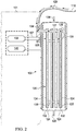
FIG. 2 shows an exploded, cross-sectional view of the canister and a partially schematic cross-sectional view of the reduced pressure treatment unit comprising components of the bodily fluid collection system ofFIG. 1 ; -
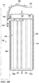
FIG. 2A shows the canister ofFIG. 2 with the container partially filled with bodily fluids drawn from the fluid collection system; -
FIG. 2B shows the canister ofFIG. 2 with the container completely filled with bodily fluids drawn from the fluid collection system; and -
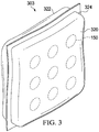
FIG. 3 shows a perspective view of a second embodiment of a container for collecting bodily fluids in the bodily fluid collection system ofFIG. 1 . - In the following detailed description of several illustrative embodiments, reference is made to the accompanying drawings that form a part hereof, and in which is shown by way of illustration specific preferred embodiments in which the invention may be practiced. These embodiments are described in sufficient detail to enable those skilled in the art to practice the invention, and it is understood that other embodiments may be utilized and that logical structural, mechanical, electrical, and chemical changes may be made without departing from the spirit or scope of the invention. To avoid detail not necessary to enable those skilled in the art to practice the embodiments described herein, the description may omit certain information known to those skilled in the art. The following detailed description is, therefore, not to be taken in a limiting sense, and the scope of the illustrative embodiments are defined only by the appended claims.
- The term "reduced pressure" as used herein generally refers to a pressure less than the ambient pressure at a tissue site that is being subjected to treatment. In most cases, this reduced pressure will be less than the atmospheric pressure at which the patient is located. Alternatively, the reduced pressure may be less than a hydrostatic pressure associated with tissue at the tissue site. Although the terms "vacuum" and "negative pressure" may be used to describe the pressure applied to the tissue site, the actual pressure reduction applied to the tissue site may be significantly less than the pressure reduction normally associated with a complete vacuum. Reduced pressure may initially generate fluid flow in the area of the tissue site. As the hydrostatic pressure around the tissue site approaches the desired reduced pressure, the flow may subside, and the reduced pressure is then maintained. Unless otherwise indicated, values of pressure stated herein are gauge pressures. Similarly, references to increases in reduced pressure typically refer to a decrease in absolute pressure, while decreases in reduced pressure typically refer to an increase in absolute pressure.
- The term "tissue site" as used herein refers to a wound or defect located on or within any tissue, including but not limited to, bone tissue, adipose tissue, muscle tissue, neural tissue, dermal tissue, vascular tissue, connective tissue, cartilage, tendons, or ligaments. The term "tissue site" may further refer to areas of any tissue that are not necessarily wounded or defective, but are instead areas in which it is desired to add or promote the growth of additional tissue. For example, reduced pressure tissue treatment may be used in certain tissue areas to grow additional tissue that may be harvested and transplanted to another tissue location.
- Referring to
FIGS. 1 and2 , a reducedpressure treatment system 10 comprises afluid collection system 100 for applying reduced pressure therapy to a patient, a reducedpressure treatment unit 101 for providing the reduced pressure, and acanister 102 fluidly coupled between thefluid collection system 100 and the reducedpressure treatment unit 101 for collecting fluids from a patient according to one illustrative embodiment. Thecanister 102 comprises acontainer 103 having a chamber, aninlet 104 being a coupling for providing fluid communication into the chamber of thecontainer 103, and anoutlet 105 being a coupling for providing fluid communication out from the chamber of thecontainer 103. Theinlet 104 is adapted to be fluidly coupled to thefluid collection system 100 for providing reduced pressure to thefluid collection system 100 and receiving bodily fluids from the patient. Theoutlet 105 is adapted to be connected to a reducedpressure port 107 of the reducedpressure treatment unit 101 to provide reduced pressure to thefluid collection system 100 from a reducedpressure source 108 that may be contained within the reducedpressure treatment unit 101. Theinlet 104 and theoutlet 105 are preferably disposed at one end of thecontainer 103 so that both may be positioned at a higher elevation relative to the other end of thecontainer 103 when thecanister 102 is utilized in operation. Thecanister 102 may further comprise a support member such as, for example, acarrier ring 109 that may be releasably connected to the reducedpressure treatment unit 101 to hold thecontainer 103 in place during operation of the reducedpressure treatment unit 101. - The
fluid collection system 100 is adapted to be positioned proximate atissue site 110 of a patient for delivering reduced pressure to thetissue site 110 and collecting bodily fluids from thetissue site 110. Thefluid collection system 100 comprises a manifold 112 in fluid communication with thetissue site 110 and adrape 114 adapted to cover the manifold 112 for providing a substantially airtight seal over thetissue site 110. Thefluid collection system 100 may further comprise aconnector 116 fluidly coupled to the manifold 112 through thedrape 114 and a conduit ortube 118 containing at least one lumen for the transmission of fluids, both gaseous and liquid. Thetube 118 is adapted to be fluidly coupled between theconnector 116 and theinlet 104 of thecanister 102 for transmitting fluids between thecanister 102 and thetissue site 110. - The manifold 112 may be a bioabsorbable or bioinert material capable of distributing reduced pressure at various desired levels. The
drape 114 may include an adhesive seal (not shown) that not only maintains the reduced pressure at various levels, but also holds thefluid collection system 100 in place over thetissue site 110. The manifold 112 may be a bioabsorbable or bioinert material capable of distributing reduced pressure to thetissue site 110. In one embodiment, the manifold 112 may be an open cell, reticulated foam comprising, for example, a polyurethane material. The wound dressing 112 delivers reduced pressure to thetissue site 110 to provide therapeutic treatment to thetissue site 110 and allows exudates and bodily fluids to flow from thetissue site 110 to thecanister 102 where the exudates and bodily fluids are collected. - The reduced
pressure treatment unit 101 may comprise the reducedpressure source 108 as described above. The reducedpressure source 108 may be, for example, a vacuum pump driven by a motor. In another embodiment, reduced pressure may be provided by a manually-actuated pump such as a compressible bellows pump. In still another embodiment, the reduced pressure may be provided by a wall suction port either with or without a separate pressure regulator. The reducedpressure treatment unit 101 may also comprise a processing unit (not shown) for controlling various features of the reducedpressure treatment unit 101 such as, for example, the level and timing of the reduced pressure being applied to thetissue site 110. The reducedpressure treatment unit 101 may further comprise other equipment such as, for example, a source of positive pressure. - The
container 103 may be constructed of a liquid impervious material such as, for example, a thermoplastic material such as polyurethane to contain the exudates and bodily fluids collected from thetissue site 110. The chamber of thecontainer 103 may have a volume that is preferably variable to accommodate the collection of exudates and bodily fluids from thetissue site 110 expanding from an empty state to a full state after collecting such fluids. In one embodiment, thecontainer 103 may comprise a flexible bag having walls that are elastic and expandable as needed to accommodate the collection of exudates and bodily fluids. In another embodiment, the flexible bag may have walls that are less elastic or inelastic but nonetheless collapsible in the empty state and expandable to the full state as needed to accommodate the collection of exudates and bodily fluids. In one embodiment, thecontainer 103 may comprise a flexible bag formed from a single tubular sheet of film sealed at both ends. In another embodiment, thecontainer 103 may comprise a flexible bag formed from two sheets of film sealed around the edges and shown more specifically inFIG. 1 which shows the chamber having an oval shape. The chamber of thecontainer 103 may have a circular or rectangular shape (e.g., see the chamber ofcontainer 303 inFIG. 3 ) as necessary to accommodate the structure and fluidics of the system. - In yet another embodiment, the
container 103 may comprise two walls joined around the edges by a connecting member that provides expandability of the chamber of thecontainer 103. Referring more specifically toFIG. 2 , thecontainer 103 may comprise afirst wall 120, asecond wall 122, and a connectingmember 124, wherein the perimeters of thefirst wall 120 and thesecond wall 122 are joined together by the connectingmember 124. Thefirst wall 120, thesecond wall 122, and the connectingmember 124 define the chamber of thecontainer 103 that may accommodate the exudates and bodily fluids as they are collected from thetissue site 110. In one embodiment, the connectingmember 124 may comprise one ormore pleats 126 that allow the chamber of thecontainer 103 to expand from the empty state to the filled state. In another embodiment, the connectingmember 124 may comprise a material with elastic characteristics. In yet another embodiment, the connectingmember 124 may be configured as a Z-fold to permit expansion of the chamber of thecontainer 103. Other configurations of thecontainer 103 may provide similar volumetric expandability of the chamber. - As indicated above, the
inlet 104 and theoutlet 105 are preferably disposed at one end of thecontainer 103 so that both may be positioned at a higher elevation relative to the other end of thecontainer 103 when thecanister 102 is utilized in operation. Thus, thecontainer 103 may be oriented more vertically with theinlet 104 and theoutlet 105 being elevated to utilize gravity to facilitate filling the chamber of thecontainer 103 with the exudates and bodily fluids being collected. In one embodiment, thecontainer 103 may contain an absorptive material such as a foam, hydrogel, or a water-swelling polymer for collecting and treating the exudates and bodily fluids being collected from thetissue site 110. In such embodiments, it is also desirable that the exudates and bodily fluids enter the chamber of thecontainer 103 on the distal side of thecontainer 103 adjacent thefirst wall 120 allowing the absorptive material to trap and collect the liquid fluids while the gaseous fluids exit the chamber of thecontainer 103 on the proximal side of thecontainer 103 adjacent thesecond wall 122. Thus, theinlet 104 and theoutlet 105 may be disposed on opposing walls of thecontainer 103. In another embodiment as more specifically shown in the figures, theinlet 104 and theoutlet 105 may both be disposed on the proximal side of thecontainer 103 through thesecond wall 122 wherein theinlet 104 is in fluid communication with atube 127 having adistal end 128 extending within the chamber to the distal side of thecontainer 103 adjacent thefirst wall 120 so that the absorptive material better traps and collects the liquid fluids while the gaseous fluids exit the chamber of thecontainer 103 through theoutlet 105 as illustrated byarrows 129 representing the flow of the fluids. - When the
container 103 is filled with an absorptive material in bulk volume, the absorbent material often failed to expand or inflate thecontainer 103 to completely fill the chamber of thecontainer 103 with the exudates and bodily fluids being collected from thetissue site 110. Moreover, the absorptive material tended to saturate in localized areas without absorbing the fluids throughout the entire volume of the absorptive material. Even when thecontainer 103 and the absorptive material within thecontainer 103 were oriented vertically, the vertical orientation exacerbated the localized saturation condition. It is desirable to overcome these problems so that thecontainer 103 would be completely filled to reduce the expense associated with utilizing additional containers and reduce the maintenance required by the patient or a caregiver. - These problems are overcome by disposing individual layers of absorptive material within the
container 103 wherein the absorptive layers are spaced apart from one another that may form an absorptive lamination to enhance the collection and flow of fluids throughout the entire volume of the absorptive lamination. These problems are further overcome by interleaving layers of wicking material within the space between the absorptive layers to further enhance the flow of fluids between the absorptive layers and throughout the entire volume of the absorptive lamination. Using such an absorptive lamination including wicking layers interleaved between the absorptive layers within thecontainer 103 greatly enhances the ability of thecontainer 103 to expand and completely fill to overcome these problems and do so regardless of orientation. When thecontainer 103 contains an absorptive lamination as just described, the absorptive capabilities of thecontainer 103 are still enhanced when the container is oriented in a horizontal position as opposed to a vertical position. - Referring more specifically to
FIG. 2 , one exemplary embodiment of anabsorptive lamination 130 is shown and comprises a plurality ofabsorptive layers 132 of absorptive material that are spaced apart from each other as described above. Theabsorptive layers 132 may be spaced apart from each other by spacers (not shown) or any other means to maintain the spaced apart relationship between theabsorptive layers 132 when subjected to a reduced pressure during operation of the reducedpressure treatment unit 101. Theabsorptive lamination 130 contains a plurality of wickinglayers 134 of wicking material disposed between theabsorptive layers 132. In one embodiment, onewicking layer 134 may be disposed or interleaved between eachabsorptive layer 132 as described above but not shown. In another embodiment, onewicking layer 134 may be disposed proximate each side of one of theabsorptive layers 132 such that a pair of wickinglayers 134 may be associated with eachabsorptive layer 132 as shown. In this embodiment, theabsorptive lamination 130 may further comprisespacers 135 disposed between each pair of wickinglayers 134 to provide further spacing between theabsorptive layers 132. Theabsorptive lamination 130 may be oriented within the chamber of thecontainer 103 so that theabsorptive layers 132 and the wicking layers 134 are substantially parallel to thefirst wall 120 and thesecond wall 122 of thecontainer 103. These embodiments enhance the distribution of bodily fluids to theabsorptive layers 132 throughout the entire chamber of thecontainer 103 to enhance the fluid storage capability of theabsorptive lamination 130. - The wicking layers 134 may comprise a wicking material having flow channels that support the flow of fluids at least through the width of each
wicking layer 134, i.e., generally perpendicular to the length or longitudinal axis of thewicking layer 134. The flow channels of the wicking material are capable of supporting the flow of fluids even when under reduced pressure being applied within thecontainer 103. The wicking material may be a non-woven material such as, for example, Libeltex TDL2 available from LIBELTEX bvba located in Belgium, or a reticulated open-cell polyurethane foam. Theabsorptive layers 132 may comprise, for example, a textile substrate (e.g., woven or knit fabrics), a foam, a hydrogel, a hydrocolloid, a superabsorbent polymer (e.g., Texsus CCBSL 130LL available from Texsus Spa located in Italy), a silica gel, a water swelling polymer, a polysaccharide (e.g., chitosan, carboxymethylcellulose, hydroxylmethylcellulose, hyaluronic acid, alginate, pectin, etc.), a proteinaceous material (glycoprotein, gelatin, etc.), and combinations thereof. - The wicking layers 134 and the
absorptive layers 132 of may each further comprise an antimicrobial agent and thus be adapted to have antimicrobial properties to effect a bioburden log reduction of greater than one or, more preferably, greater than three. By way of a non-limiting example, this antimicrobial property may be accomplished by adding ionic silver to the wicking material of the wicking layers 134 or the absorptive material of the absorptive layers 132. The wicking layers 134 and theabsorptive layers 132 of may each further comprise other chemicals or agents to facilitate the collection and storage of exudates and bodily fluids from thetissue site 110. - The
canister 102 may further comprise a first textured layer 136 contained within thecontainer 103 adjacent to thefirst wall 120 and a second textured layer 137 contained within thecontainer 103 adjacent to thesecond wall 122. The first textured layer 136 and the second textured layer 137 may be constructed from a fluid impermeable material. The first textured layer 136 and the second textured layer 137 may each be a sheet of material having a textured side that is corrugated or comprises a plurality of protrusions or projections extending into the chamber of thecontainer 103 and facing theabsorptive lamination 130. The textured sides of the first textured layer 136 and the second textured layer 137 may have other shapes resulting from being channeled, creased, folded, grooved, indented, pleated, or ribbed. When the chamber of thecontainer 103 subjected to a reduced pressure, the first textured layer 136 and the second textured layer 137 collapse against the sides of theabsorptive lamination 130. The first textured layer 136 and the second textured layer 137 may provide a fluid reservoir for a bolus of bodily fluid entering thecontainer 103, allowing the bodily fluid from thetissue site 110 to be distributed more thoroughly across the face of theabsorptive lamination 130 to enhance the ability of theabsorptive layers 132 collect and store such fluids. Additionally, textured surfaces of the first textured layer 136 and the second textured layer 137 provide additional spacing adjacent the outermostabsorptive layers 132 and/or the wicking layers 134 to further enhance the flow of bodily fluids throughout the entireabsorptive lamination 130. - The
absorptive layers 132 and the wicking layers 134 may be organized in other alternating sequences of absorptive material and wicking material. Additionally, theabsorptive layers 132 and the wicking layers 134 may be formed into a composite rather than being discrete layers of material. For example, an absorptive composite may be formed from co-extruding absorptive material and wicking material such that the absorptive composite possesses characteristics similar to the characteristics of the discreteabsorptive layers 132 and the wicking layers 134. The absorptive and wicking lamina of the absorptive composite would then be aligned in an alternating sequence when disposed within thecontainer 103. - In operation, the
absorptive lamination 130 including wicking layers interleaved between the absorptive layers within thecontainer 103 greatly enhances the ability of thecontainer 103 to expand and completely fill the chamber as described above, especially when oriented in a generally vertical position. Referring more specifically toFIGS. 2 ,2A , and2B , thecontainer 102 of thecanister 102 is shown as being substantially vertically oriented and expanding from an empty state to being partially filled and then completely filled, respectively. Referring toFIG. 2A , thecontainer 102 is shown as being partially filled with bodily fluids and expanding at the lower end near the bottom of thecontainer 102. The bodily fluids and exudates are drawn from thetissue site 110 into theinlet 104 and thetube 127, and then flow into the chamber of thecontainer 102 through thedistal end 128 of thetube 127. When the bodily fluids enter the chamber of thecontainer 102, they begin to separate into gaseous and liquid components with the gaseous fluids exiting theoutlet 105 as indicated by thearrows 129 and the liquid fluids manifolding down the side of theabsorptive lamination 130 with the assistance of gravity as indicated byliquid line 139. The liquid bodily fluids are manifolded through a combination of the wicking action created by the wicking layers 134 and the osmotic pressure of theabsorptive layers 132, and supplemented by the effects of gravity which pulls the fluid downward toward the bottom of thecontainer 102 which begins to expand along with the expandingabsorptive layers 132. This leaves the top of thecontainer 102 generally unobstructed by the liquid fluids to manifold the reduced pressure through thetube 127 to theoutlet 105. This action also facilitates fluid flow by pulling intermittent bolus' of liquid fluids and exudates from thetissue site 110 down to the bottom of thecontainer 102 by gravity where theabsorbent layers 132 have more time to trap and retain the liquid fluids. - As can be seen in the illustration, the
absorptive layers 132 continue to expand as the wicking layers 132 continue to channel the liquid fluids across the surfaces of theabsorptive layers 132 and the longer theabsorptive layers 132 are submersed in the liquid fluids. For example, the most distalabsorptive layer 132a has expanded more at the lower end which has expanded more than the lower end of the most proximalabsorptive layer 132b with varying degrees of absorption and expansion for each interveningabsorptive layer 132. As thecontainer 102 continues to fill with the liquid fluids, theabsorptive layers 132 continue to expand until they reach a full capacity such that thecontainer 102 is fully expanded in a filled state as shown inFIG. 2B . When the chamber of thecontainer 102 is substantially filled, the liquid fluid eventually covers thedistal end 128 of thetube 127 as shown by fluid line 139' which substantially prevents the continuing flow of bodily fluids from thetissue site 110. Thecontainer 102 is capable of expanding with the expansion of theabsorptive lamination 132 by means of any of the embodiments described above. It should be understood that thecontainer 102 will function in a substantially horizontal position by virtue of the wicking action provided by the wicking layers 134 without the aid of gravity as long as thedistal end 128 of thetube 127 is in an elevated position. - Referring now to
FIG. 3 , acontainer 303 is shown is substantially similar in all respects to thecontainer 103 ofFIGS. 1 and2 except for the shape as pointed out above. Thecontainer 303 also comprises afirst wall 320 and asecond wall 322 joined together by the connectingmember 324. As also described above, thecontainer 303 may be constructed of a liquid impervious material such as, for example, a thermoplastic such as polyurethane. In one exemplary embodiment, thefirst wall 320 and thesecond wall 322 of thecontainer 303 may be constructed of polyurethane film having a cross-sectional thickness greater than about 50µm wherein thecontainer 303 is substantially impervious to vapor. In another exemplary embodiment, thefirst wall 320 and asecond wall 322 of thecontainer 303 may comprise a material permeable to vapor such as, for example, the same polyurethane film wherein the polyurethane film has a cross-sectional thickness less than about 50µm but greater than about 15µm. If thecontainer 303 is permeable to vapor, the reducedpressure treatment unit 101 may further comprise apositive pressure source 140 that may provide positive pressure to thecontainer 303 to facilitate the evaporation of collected bodily fluid into vapor and the subsequent transmission of vapor through thecontainer 303 and into the atmosphere. In one embodiment, the source ofpositive pressure 140 may be the exhaust of the sourcenegative pressure 108. In another embodiment, thepositive pressure source 140 may be activated when thenegative pressure source 108 is deactivated. - In yet another exemplary embodiment, the
first wall 320 and thesecond wall 322 of thecontainer 303 may be substantially impervious to vapor but may further comprise portions orregions 150 having a cross-sectional thickness greater than about 5µm and less than about 50µm that are permeable to vapor. Theregions 150 of vapor permeability allow bodily fluid collected in thecontainer 303 to evaporate into the atmosphere as described above and further assisted by providing positive pressure to the chamber of thecontainer 303. Theregions 150 may have varying shapes such as, for example, the shape of a regular polygon or an ellipse. Theregions 150 may comprise between about 5% and about 95% of the surface area of thecontainer 303. - In yet another embodiment, a method for collecting bodily fluid from a tissue site is provided. The method comprises disposing a plurality of absorptive layers with wicking layers interleaved between the absorptive layers into a container of a bodily fluid canister, fluidly coupling the container to both a source of bodily fluid and a source of negative pressure, and applying negative pressure through the container to the source of bodily fluid. The method further comprises utilizing the negative pressure to draw the bodily fluids from the tissue site and manifold the bodily fluids to the absorptive layers to collect and trap the liquid portion of the bodily fluids, and allowing the container to volumetrically expand as the absorptive layers swell in size, whereby the container expands to a full state after the absorptive layers are fully absorbed with the liquid fluids.
- It will be appreciated that the illustrative embodiments described herein may be used with reduced pressure treatment systems of any type, shape, or size and similarly with canisters of any type, shape, or size. The location of the inlet, outlet, semi-permeable membrane, and flexible bag may also vary depending upon the particular collection system design. Similarly, the geometry of the semi-permeable membrane may be modified as necessary to conform to the contours or configuration of the canister. Similarly, the location of the means to withdraw the collected absorbent may also vary depending upon the particular collection system design.
- It should be apparent from the foregoing that an invention having significant advantages has been provided. While the invention is shown in only a few of its forms, it is not just limited but is susceptible to various changes and modifications without departing from the spirit thereof.
- Aspects of the invention are disclosed in the following numbered clauses:
- 1. A fluid collection system for collecting bodily fluids from a tissue site using reduced pressure, the fluid collection device comprising:
- a canister comprising an inlet, an outlet, and a container, said inlet adapted to be in fluid communication with a wound dressing in a tissue site, said outlet adapted to be in fluid communication with a reduced pressure source, and said container configured to be volumetrically expandable, substantially impervious to fluid, and in fluid communication with said inlet and said outlet; and
- a plurality of layers of wicking material positioned proximate to a plurality of layers of absorptive material, said plurality of layers of wicking material and said plurality of layers of absorptive material disposed within said container.
- 2. The system as in clause 1 , said container further comprising a first wall, a second wall, and a connecting member, said first wall and said second wall oriented essentially parallel to said plurality of layers of manifold material, and said connecting member sealingly fixed to said first wall and to said second wall whereby said first wall, said second wall, and said connecting member define a chamber.
- 3. The system as in clause 1, further comprising a tube situated within said container, said tube in fluid communication with said inlet and in fluid communication with said chamber, and oriented essentially perpendicular to said plurality of layers of manifold material.
- 4. The system as in clause 1, wherein said container is a thermoplastic.
- 5. The system as in clause 2, wherein said first wall is adapted to translate away from said second wall.
- 6. The system as in clause 1, further comprising a first textured layer contained within said container and proximate to said first wall, said first textured layer having at least one textured side wherein said at least one textured side is oriented towards said plurality of layers of manifold material.
- 7. The system as in
clause 6, further comprising a second textured layer contained within said container and proximate to said second wall, said second textured layer having at least one textured side wherein said at least one textured side is oriented towards said plurality of layers of manifold material. - 8. The system as in clause 1, wherein said antimicrobial agent is distributed within at least one of said plurality of layers of manifold material.
- 9. The system as in clause 1, wherein said antimicrobial agent is distributed within at least one of said plurality of layers of absorptive material.
- 10. The system as in either clause 8 or clause 9, wherein said antimicrobial agent exhibits a log reduction for microorganisms of at least about 1.
- 11. The system as in either clause 8 or clause 9, wherein said antimicrobial agent exhibits a log reduction for microorganisms of at least about 3.
- 12. The system as in clause 1, wherein said container is adapted to be permeable to vapor.
- 13. The system as in clause 12, wherein said container comprises a polyurethane material having a cross-sectional thickness less than about 50 µm and greater than about 15 µm.
- 14. The system as in clause 12, wherein said container comprises thermoplastic material having a cross-sectional thickness greater than about 50 µm and said container further comprises a plurality of regions wherein said plurality of regions comprise between about 5% and about 95% of the container surface area and said plurality of regions have a cross-sectional thickness less than about 50 µm and greater than about 5 µm.
- 15. The system as in clause 12, said container further comprising a positive pressure port adapted to be in fluid communication with a positive pressure source.
- 16. Method for volumetrically expanding a bodily fluid canister, the method comprising: introducing bodily fluid into a canister, said canister comprising a container, said
container containing a plurality of layers of absorptive material within said canister adapted to retain bodily fluid and a plurality of layers of wicking material within said canister adapted to distribute bodily fluid along said plurality of layers of absorptive material,
volumetrically expanding said canister wherein said container is adapted to expand to accommodate changes in dimensions of said plurality of layers of absorptive material and of said plurality of layers of manifold material. - 17. A bodily fluid collection system comprising:
- a canister comprising an inlet, an outlet, and a container, said container comprising a first surface, a second surface, and a connecting member, said first and said second surface configured in an essentially parallel orientation, said connecting member fixed along perimeters of said first surface and said second surface, said container configured to be volumetrically expandable and substantially impervious to fluid, said inlet adapted to be in fluid communication with a wound dressing in a tissue site, said inlet located on top portion of said first surface of said container, said outlet adapted to be in fluid communication with a reduced pressure source, said outlet located on top portion of said second surface of said container; a plurality of layers of wicking material and a plurality of layers of absorptive material, said plurality of wicking material layers and said plurality of absorptive material layers oriented within said container essentially parallel to said first surface, said plurality of wicking material layers and said plurality of absorptive material layers positioned wherein each layer of said absorptive material is proximate to at least one layer of said manifold material; and
- a tube situated within said container, said tube in fluid communication with said inlet, in fluid communication with said container, and oriented essentially perpendicular to said plurality of layers of manifold material.
- 18. A canister for collecting bodily fluids from a fluid collection system for delivering reduced pressure to a tissue site from a source of reduced pressure, the canister comprising:
- a container having a chamber being expandable to receive and collect bodily fluids from the tissue site in response to the application of the reduced pressure;
- an inlet fluidly coupled to the chamber of the container and configured to be in fluid communication with the fluid collection system for delivering the bodily fluids into the chamber of the container;
- an outlet fluidly coupled to the chamber of the container and configured to be in fluid communication with the source of reduced pressure for providing reduced pressure through the chamber of the container to the fluid collection system; and an absorptive lamination disposed within the container and adapted to trap and collect a liquid portion of the bodily fluids separated from the gaseous portion of the bodily fluids flowing from the inlet to the outlet within the container, wherein the container expands as the absorptive lamination swells to absorb the liquid portion of the bodily fluids.
- 19. The canister of clause 18, wherein the absorptive lamination comprises a plurality of absorptive layers spaced apart within the container.
- 20. The canister of clause 18, wherein the absorptive lamination comprises a plurality of absorptive layers and a plurality of wicking layers interleaved between the absorptive layers.
- 21. The canister of clause 18, wherein the absorptive lamination comprises a plurality of absorptive layers and a plurality of wicking layers disposed proximate each side of one of the absorptive layers such that a pair of wicking layers associated with each absorptive layer.
- 22. The canister of clause 21, wherein the absorptive lamination further comprises spacers disposed between each pair of wicking layers.
- 23. The canister of clause 18, wherein the container comprises a flexible bag having walls formed from an elastic material wherein the walls stretch allowing the container expands with the swelling of the absorptive lamination.
- 24. The canister of clause 18, wherein the container comprises a flexible bag having walls formed from a substantially inelastic material wherein the walls are collapsible when the container is empty but expandable so that the container expands with the swelling of the absorptive lamination.
- 25. The canister of clause 18, wherein the container comprises a first wall and a second wall joined around the edges by a connecting member being expandable to allow the container to expand with the swelling of the absorptive lamination.
- 26. The canister of clause 25, wherein the connecting member comprises pleats.
- 27. The canister of clause 25, wherein the connecting member comprises an elastic material.
- 28. The canister of clause 25, wherein the container comprises an upper end and a lower end wherein the upper end is adapted to be elevated in operation, and wherein the inlet and outlet are disposed in the upper end of the container.
- 29. The canister of clause 28, wherein the inlet and outlet are disposed on opposing walls of the first wall and the second wall of the container.
- 30. The canister of clause 28, wherein the inlet and outlet are disposed on either one of the first wall and the second wall of the container and wherein the canister further comprises a two fluidly coupled to the inlet and extending into the chamber of the container away from the outlet.
- 31. The canister of clause 25, wherein the canister further comprises a first textured layer disposed within the container adjacent the first wall.
- 32. The canister of clause 25, wherein the canister further comprises a second textured layer disposed within the container adjacent the second wall.
- 33. The canister of clause 18, wherein the container comprises a liquid impermeable material.
- 34. The canister of clause 33, wherein the permeable material is polyurethane having a cross-sectional thickness between about 15 µm and about 50 µm.
- 35. The canister of clause 18, wherein a first portion of the container comprises a liquid impermeable material and a second portion of the container comprises a vapor permeable material.
- 36. The canister of clause 35, wherein the vapor permeable material is polyurethane having a cross-sectional thickness between about 5 µm and about 50 µm.
Claims (19)
- A canister for collecting bodily fluids from a fluid collection system for delivering reduced pressure to a tissue site from a source of reduced pressure, the canister comprising:a container having a chamber configured to be expandable to receive and collect bodily fluids from the tissue site in response to the delivery of the reduced pressure;an inlet fluidly coupled to the chamber of the container and configured to be in fluid communication with the fluid collection system for delivering the bodily fluids into the chamber of the container;an outlet fluidly coupled to the chamber of the container and configured to be in fluid communication with the source of reduced pressure for providing reduced pressure through the chamber of the container to the fluid collection system; andan absorptive lamination disposed within the container and adapted to trap and collect a liquid portion of the bodily fluids separated from a gaseous portion of the bodily fluids flowing from the inlet to the outlet within the container, wherein the container expands as the absorptive lamination swells to absorb the liquid portion of the bodily fluids.
- The canister of claim 1, wherein the absorptive lamination comprises a plurality of absorptive layers spaced apart within the container.
- The canister of claim 1, wherein the absorptive lamination comprises a plurality of absorptive layers and a plurality of wicking layers interleaved between the absorptive layers.
- The canister of claim 1, wherein the absorptive lamination comprises a plurality of absorptive layers and a pair of wicking layers associated with each absorptive layer.
- The canister of claim 4, wherein the absorptive lamination further comprises spacers disposed between each pair of wicking layers.
- The canister of claim 1, wherein the container comprises a flexible bag having walls formed from an elastic material wherein the walls are configured to stretch allowing the container to expand with the swelling of the absorptive lamination.
- The canister of claim 1, wherein the container comprises a flexible bag having walls formed from a substantially inelastic material wherein the walls are collapsible when the container is empty but expandable so that the container expands with the swelling of the absorptive lamination.
- The canister of claim 1, wherein the container comprises a first wall and a second wall joined around the edges by a connecting member configured to be expandable to allow the container to expand with the swelling of the absorptive lamination.
- The canister of claim 8, wherein the connecting member comprises pleats.
- The canister of claim 8, wherein the connecting member comprises an elastic material.
- The canister of claim 8, wherein the container comprises an upper end and a lower end wherein the upper end is adapted to be elevated in operation, and wherein the inlet and the outlet are disposed in the upper end of the container.
- The canister of claim 11, wherein the inlet and the outlet are disposed on opposing walls of the first wall and the second wall of the container.
- The canister of claim 11, wherein the inlet and the outlet are disposed on either one of the first wall and the second wall of the container and wherein the canister further comprises a tube fluidly coupled to the inlet and extending into the chamber of the container away from the outlet.
- The canister of claim 8, wherein the canister further comprises a first textured layer disposed within the container adjacent the first wall.
- The canister of claim 8, wherein the canister further comprises a second textured layer disposed within the container adjacent the second wall.
- The canister of claim 1, wherein the container comprises a liquid-impermeable material.
- The canister of claim 16, wherein the liquid-impermeable material is polyurethane having a cross-sectional thickness between about 15 µm and about 50 µm.
- The canister of claim 1, wherein a first portion of the container comprises a liquid-impermeable material and a second portion of the container comprises a vapor-permeable material.
- The canister of claim 18, wherein the vapor-permeable material is polyurethane having a cross-sectional thickness between about 5 µm and about 50 µm.
Applications Claiming Priority (3)
| Application Number | Priority Date | Filing Date | Title |
|---|---|---|---|
| US201361780143P | 2013-03-13 | 2013-03-13 | |
| PCT/US2014/012818 WO2014163733A2 (en) | 2013-03-13 | 2014-01-23 | Expandable fluid collection canister |
| EP14706356.4A EP2968702B1 (en) | 2013-03-13 | 2014-01-23 | Expandable fluid collection canister |
Related Parent Applications (2)
| Application Number | Title | Priority Date | Filing Date |
|---|---|---|---|
| EP14706356.4A Division EP2968702B1 (en) | 2013-03-13 | 2014-01-23 | Expandable fluid collection canister |
| EP14706356.4A Division-Into EP2968702B1 (en) | 2013-03-13 | 2014-01-23 | Expandable fluid collection canister |
Publications (1)
| Publication Number | Publication Date |
|---|---|
| EP3613450A1 true EP3613450A1 (en) | 2020-02-26 |
Family
ID=50159509
Family Applications (2)
| Application Number | Title | Priority Date | Filing Date |
|---|---|---|---|
| EP14706356.4A Active EP2968702B1 (en) | 2013-03-13 | 2014-01-23 | Expandable fluid collection canister |
| EP19196635.7A Withdrawn EP3613450A1 (en) | 2013-03-13 | 2014-01-23 | Expandandable fluid collection canister |
Family Applications Before (1)
| Application Number | Title | Priority Date | Filing Date |
|---|---|---|---|
| EP14706356.4A Active EP2968702B1 (en) | 2013-03-13 | 2014-01-23 | Expandable fluid collection canister |
Country Status (3)
| Country | Link |
|---|---|
| US (3) | US10092682B2 (en) |
| EP (2) | EP2968702B1 (en) |
| WO (1) | WO2014163733A2 (en) |
Families Citing this family (44)
| Publication number | Priority date | Publication date | Assignee | Title |
|---|---|---|---|---|
| GB0808376D0 (en) | 2008-05-08 | 2008-06-18 | Bristol Myers Squibb Co | Wound dressing |
| GB0817796D0 (en) | 2008-09-29 | 2008-11-05 | Convatec Inc | wound dressing |
| GB201020236D0 (en) | 2010-11-30 | 2011-01-12 | Convatec Technologies Inc | A composition for detecting biofilms on viable tissues |
| WO2012078781A1 (en) | 2010-12-08 | 2012-06-14 | Convatec Technologies Inc. | Integrated system for assessing wound exudates |
| CN103347562B (en) | 2010-12-08 | 2016-08-10 | 康沃特克科技公司 | Wound exudate system accessory |
| GB201115182D0 (en) | 2011-09-02 | 2011-10-19 | Trio Healthcare Ltd | Skin contact material |
| GB2497406A (en) | 2011-11-29 | 2013-06-12 | Webtec Converting Llc | Dressing with a perforated binder layer |
| GB201120693D0 (en) | 2011-12-01 | 2012-01-11 | Convatec Technologies Inc | Wound dressing for use in vacuum therapy |
| US20150354096A1 (en) | 2012-12-20 | 2015-12-10 | Convatec Technologies Inc. | Processing of chemically modified cellulosic fibres |
| US10016542B2 (en) * | 2013-03-13 | 2018-07-10 | Kci Licensing, Inc. | Collapsible canister for use with reduced pressure therapy device |
| WO2014163733A2 (en) * | 2013-03-13 | 2014-10-09 | Kci Licensing, Inc. | Expandable fluid collection canister |
| HUE049136T2 (en) | 2015-04-27 | 2020-08-28 | Smith & Nephew | Reduced pressure apparatuses |
| US10166140B2 (en) * | 2015-06-25 | 2019-01-01 | Somnics, Inc. | Liquid container and absorbent insert for oral negative-pressure therapy system |
| US10561767B2 (en) * | 2015-10-21 | 2020-02-18 | Umpqua Research Company | Medical suction device |
| DE102015015559B4 (en) * | 2015-12-03 | 2022-08-11 | Primed Halberstadt Medizintechnik Gmbh | Arrangement for removing wound exudate from body cavities |
| DE202016100154U1 (en) * | 2016-01-14 | 2017-04-20 | Pfm Medical Ag | System for drainage of fluids or wound secretions |
| CN109069301B (en) | 2016-03-07 | 2021-11-30 | 史密夫及内修公开有限公司 | Wound therapy apparatus and method utilizing a negative pressure source integrated into a wound dressing |
| CN109310528B (en) | 2016-03-30 | 2021-07-20 | 康沃特克科技公司 | Detecting microbial infection in a wound |
| US11740241B2 (en) | 2016-03-30 | 2023-08-29 | Synovo Gmbh | Construct including an anchor, an enzyme recognition site and an indicator region for detecting microbial infection in wounds |
| EP4049692A1 (en) | 2016-04-26 | 2022-08-31 | Smith & Nephew PLC | Wound dressings and methods of use with integrated negative pressure source having a fluid ingress inhibition component |
| JP6975170B2 (en) | 2016-05-03 | 2021-12-01 | スミス アンド ネフュー ピーエルシーSmith & Nephew Public Limited Company | Optimization of power transfer to negative pressure sources in negative pressure therapy systems |
| WO2017191158A1 (en) | 2016-05-03 | 2017-11-09 | Smith & Nephew Plc | Systems and methods for driving negative pressure sources in negative pressure therapy systems |
| WO2017191154A1 (en) | 2016-05-03 | 2017-11-09 | Smith & Nephew Plc | Negative pressure wound therapy device activation and control |
| JP7071957B2 (en) | 2016-07-08 | 2022-05-19 | コンバテック・テクノロジーズ・インコーポレイテッド | Flexible negative pressure system |
| CA3030153C (en) | 2016-07-08 | 2023-10-24 | Convatec Technologies Inc. | Fluid flow sensing |
| CA3030151A1 (en) * | 2016-07-08 | 2018-01-11 | Convatec Technologies Inc. | Fluid collection apparatus |
| EP3503857B1 (en) | 2016-08-25 | 2024-04-17 | Smith & Nephew plc | Absorbent negative pressure wound therapy dressing |
| DE102016115836A1 (en) * | 2016-08-25 | 2018-03-01 | Paul Hartmann Ag | Apparatus for the negative pressure treatment of wounds on the human body |
| WO2018060417A1 (en) | 2016-09-30 | 2018-04-05 | Smith & Nephew Plc | Negative pressure wound treatment apparatuses and methods with integrated electronics |
| EP3592312B1 (en) | 2017-03-08 | 2024-01-10 | Smith & Nephew plc | Negative pressure wound therapy device control in presence of fault condition |
| USD877889S1 (en) * | 2017-05-08 | 2020-03-10 | Kci Licensing, Inc. | Negative pressure unit |
| US11160915B2 (en) | 2017-05-09 | 2021-11-02 | Smith & Nephew Plc | Redundant controls for negative pressure wound therapy systems |
| EP3681550B1 (en) | 2017-09-13 | 2023-11-08 | Smith & Nephew PLC | Negative pressure wound treatment apparatuses |
| GB201718070D0 (en) | 2017-11-01 | 2017-12-13 | Smith & Nephew | Negative pressure wound treatment apparatuses and methods with integrated electronics |
| GB201718072D0 (en) | 2017-11-01 | 2017-12-13 | Smith & Nephew | Negative pressure wound treatment apparatuses and methods with integrated electronics |
| GB201718054D0 (en) | 2017-11-01 | 2017-12-13 | Smith & Nephew | Sterilization of integrated negative pressure wound treatment apparatuses and sterilization methods |
| EP3703632B1 (en) | 2017-11-01 | 2024-04-03 | Smith & Nephew plc | Negative pressure wound treatment apparatuses and methods with integrated electronics |
| USD898925S1 (en) | 2018-09-13 | 2020-10-13 | Smith & Nephew Plc | Medical dressing |
| WO2021084444A1 (en) * | 2019-11-01 | 2021-05-06 | Kci Licensing, Inc. | Flexible fluid storage pouch with absorbent |
| US11331221B2 (en) | 2019-12-27 | 2022-05-17 | Convatec Limited | Negative pressure wound dressing |
| US11771819B2 (en) | 2019-12-27 | 2023-10-03 | Convatec Limited | Low profile filter devices suitable for use in negative pressure wound therapy systems |
| WO2023042012A1 (en) * | 2021-09-15 | 2023-03-23 | Kci Manufacturing Unlimited Company | Negative pressure wound therapy system |
| WO2023042014A1 (en) * | 2021-09-15 | 2023-03-23 | Kci Manufacturing Unlimited Company | Fluid storage container |
| WO2023110098A1 (en) * | 2021-12-16 | 2023-06-22 | Excitus As | Device for aspirator, aspirators and method of providing device for aspirator |
Citations (6)
| Publication number | Priority date | Publication date | Assignee | Title |
|---|---|---|---|---|
| US5630855A (en) * | 1992-10-16 | 1997-05-20 | Humanteknik Ab | Moisture-collecting device |
| US20100324510A1 (en) * | 2007-06-27 | 2010-12-23 | Molnlycke Health Care Ab | device for treatment of wounds with reduced pressure |
| US20110028919A1 (en) * | 2008-04-09 | 2011-02-03 | Molnlycke Health Care Ab, | device for treatment of wounds and a method for manufacturing of wound pads |
| US20110172616A1 (en) * | 2008-02-27 | 2011-07-14 | Smith & Nephew Plc | Fluid collection |
| DE102010060543A1 (en) * | 2010-10-20 | 2012-04-26 | Birgit Riesinger | Drainage device for wound treatment using negative pressure |
| US20130053797A1 (en) * | 2011-08-31 | 2013-02-28 | Christopher Brian Locke | Inline storage pouches for use with body fluids |
Family Cites Families (143)
| Publication number | Priority date | Publication date | Assignee | Title |
|---|---|---|---|---|
| US1355846A (en) | 1920-02-06 | 1920-10-19 | David A Rannells | Medical appliance |
| US2547758A (en) | 1949-01-05 | 1951-04-03 | Wilmer B Keeling | Instrument for treating the male urethra |
| US2632443A (en) | 1949-04-18 | 1953-03-24 | Eleanor P Lesher | Surgical dressing |
| GB692578A (en) | 1949-09-13 | 1953-06-10 | Minnesota Mining & Mfg | Improvements in or relating to drape sheets for surgical use |
| US2682873A (en) | 1952-07-30 | 1954-07-06 | Johnson & Johnson | General purpose protective dressing |
| NL189176B (en) | 1956-07-13 | 1900-01-01 | Hisamitsu Pharmaceutical Co | PLASTER BASED ON A SYNTHETIC RUBBER. |
| US2969057A (en) | 1957-11-04 | 1961-01-24 | Brady Co W H | Nematodic swab |
| US3066672A (en) | 1960-09-27 | 1962-12-04 | Jr William H Crosby | Method and apparatus for serial sampling of intestinal juice |
| US3367332A (en) | 1965-08-27 | 1968-02-06 | Gen Electric | Product and process for establishing a sterile area of skin |
| US3520300A (en) | 1967-03-15 | 1970-07-14 | Amp Inc | Surgical sponge and suction device |
| US3568675A (en) | 1968-08-30 | 1971-03-09 | Clyde B Harvey | Fistula and penetrating wound dressing |
| US3682180A (en) | 1970-06-08 | 1972-08-08 | Coilform Co Inc | Drain clip for surgical drain |
| BE789293Q (en) | 1970-12-07 | 1973-01-15 | Parke Davis & Co | MEDICO-SURGICAL DRESSING FOR BURNS AND SIMILAR LESIONS |
| US3826254A (en) | 1973-02-26 | 1974-07-30 | Verco Ind | Needle or catheter retaining appliance |
| ZA762197B (en) * | 1975-04-15 | 1977-04-27 | Int Paper Co | Fluid evacuator |
| DE2527706A1 (en) | 1975-06-21 | 1976-12-30 | Hanfried Dr Med Weigand | DEVICE FOR THE INTRODUCTION OF CONTRAST AGENTS INTO AN ARTIFICIAL INTESTINAL OUTLET |
| DE2640413C3 (en) | 1976-09-08 | 1980-03-27 | Richard Wolf Gmbh, 7134 Knittlingen | Catheter monitor |
| NL7710909A (en) | 1976-10-08 | 1978-04-11 | Smith & Nephew | COMPOSITE STRAPS. |
| GB1562244A (en) | 1976-11-11 | 1980-03-05 | Lock P M | Wound dressing materials |
| US4080970A (en) | 1976-11-17 | 1978-03-28 | Miller Thomas J | Post-operative combination dressing and internal drain tube with external shield and tube connector |
| US4139004A (en) | 1977-02-17 | 1979-02-13 | Gonzalez Jr Harry | Bandage apparatus for treating burns |
| US4184510A (en) | 1977-03-15 | 1980-01-22 | Fibra-Sonics, Inc. | Valued device for controlling vacuum in surgery |
| US4165748A (en) | 1977-11-07 | 1979-08-28 | Johnson Melissa C | Catheter tube holder |
| US4256109A (en) | 1978-07-10 | 1981-03-17 | Nichols Robert L | Shut off valve for medical suction apparatus |
| SE414994B (en) | 1978-11-28 | 1980-09-01 | Landstingens Inkopscentral | VENKATETERFORBAND |
| BR7908937A (en) | 1978-12-06 | 1981-06-30 | Svedman Paul | DEVICE FOR TREATING FABRICS, FOR EXAMPLE, SKIN |
| US4266545A (en) | 1979-04-06 | 1981-05-12 | Moss James P | Portable suction device for collecting fluids from a closed wound |
| US4284079A (en) | 1979-06-28 | 1981-08-18 | Adair Edwin Lloyd | Method for applying a male incontinence device |
| US4261363A (en) | 1979-11-09 | 1981-04-14 | C. R. Bard, Inc. | Retention clips for body fluid drains |
| US4569348A (en) | 1980-02-22 | 1986-02-11 | Velcro Usa Inc. | Catheter tube holder strap |
| ATE14835T1 (en) | 1980-03-11 | 1985-08-15 | Schmid Eduard | SKIN GRAFT PRESSURE BANDAGE. |
| US4297995A (en) | 1980-06-03 | 1981-11-03 | Key Pharmaceuticals, Inc. | Bandage containing attachment post |
| US4333468A (en) | 1980-08-18 | 1982-06-08 | Geist Robert W | Mesentery tube holder apparatus |
| US4465485A (en) | 1981-03-06 | 1984-08-14 | Becton, Dickinson And Company | Suction canister with unitary shut-off valve and filter features |
| US4392853A (en) | 1981-03-16 | 1983-07-12 | Rudolph Muto | Sterile assembly for protecting and fastening an indwelling device |
| US4373519A (en) | 1981-06-26 | 1983-02-15 | Minnesota Mining And Manufacturing Company | Composite wound dressing |
| US4392858A (en) | 1981-07-16 | 1983-07-12 | Sherwood Medical Company | Wound drainage device |
| US4419097A (en) | 1981-07-31 | 1983-12-06 | Rexar Industries, Inc. | Attachment for catheter tube |
| AU550575B2 (en) | 1981-08-07 | 1986-03-27 | Richard Christian Wright | Wound drainage device |
| SE429197B (en) | 1981-10-14 | 1983-08-22 | Frese Nielsen | SAR TREATMENT DEVICE |
| DE3146266A1 (en) | 1981-11-21 | 1983-06-01 | B. Braun Melsungen Ag, 3508 Melsungen | COMBINED DEVICE FOR A MEDICAL SUCTION DRAINAGE |
| US4551139A (en) | 1982-02-08 | 1985-11-05 | Marion Laboratories, Inc. | Method and apparatus for burn wound treatment |
| US4475909A (en) | 1982-05-06 | 1984-10-09 | Eisenberg Melvin I | Male urinary device and method for applying the device |
| EP0100148B1 (en) | 1982-07-06 | 1986-01-08 | Dow Corning Limited | Medical-surgical dressing and a process for the production thereof |
| NZ206837A (en) | 1983-01-27 | 1986-08-08 | Johnson & Johnson Prod Inc | Thin film adhesive dressing:backing material in three sections |
| US4548202A (en) | 1983-06-20 | 1985-10-22 | Ethicon, Inc. | Mesh tissue fasteners |
| US4540412A (en) | 1983-07-14 | 1985-09-10 | The Kendall Company | Device for moist heat therapy |
| US4543100A (en) | 1983-11-01 | 1985-09-24 | Brodsky Stuart A | Catheter and drain tube retainer |
| US4525374A (en) | 1984-02-27 | 1985-06-25 | Manresa, Inc. | Treating hydrophobic filters to render them hydrophilic |
| GB2157958A (en) | 1984-05-03 | 1985-11-06 | Ernest Edward Austen Bedding | Ball game net support |
| US4897081A (en) | 1984-05-25 | 1990-01-30 | Thermedics Inc. | Percutaneous access device |
| US5215522A (en) | 1984-07-23 | 1993-06-01 | Ballard Medical Products | Single use medical aspirating device and method |
| GB8419745D0 (en) | 1984-08-02 | 1984-09-05 | Smith & Nephew Ass | Wound dressing |
| US4872450A (en) | 1984-08-17 | 1989-10-10 | Austad Eric D | Wound dressing and method of forming same |
| US4655754A (en) | 1984-11-09 | 1987-04-07 | Stryker Corporation | Vacuum wound drainage system and lipids baffle therefor |
| US4826494A (en) | 1984-11-09 | 1989-05-02 | Stryker Corporation | Vacuum wound drainage system |
| US4605399A (en) | 1984-12-04 | 1986-08-12 | Complex, Inc. | Transdermal infusion device |
| US5037397A (en) | 1985-05-03 | 1991-08-06 | Medical Distributors, Inc. | Universal clamp |
| US4640688A (en) | 1985-08-23 | 1987-02-03 | Mentor Corporation | Urine collection catheter |
| US4710165A (en) | 1985-09-16 | 1987-12-01 | Mcneil Charles B | Wearable, variable rate suction/collection device |
| US4758220A (en) | 1985-09-26 | 1988-07-19 | Alcon Laboratories, Inc. | Surgical cassette proximity sensing and latching apparatus |
| US4733659A (en) | 1986-01-17 | 1988-03-29 | Seton Company | Foam bandage |
| EP0256060A1 (en) | 1986-01-31 | 1988-02-24 | OSMOND, Roger L. W. | Suction system for wound and gastro-intestinal drainage |
| US4838883A (en) | 1986-03-07 | 1989-06-13 | Nissho Corporation | Urine-collecting device |
| JPS62281965A (en) | 1986-05-29 | 1987-12-07 | テルモ株式会社 | Catheter and catheter fixing member |
| GB8621884D0 (en) | 1986-09-11 | 1986-10-15 | Bard Ltd | Catheter applicator |
| GB2195255B (en) | 1986-09-30 | 1991-05-01 | Vacutec Uk Limited | Apparatus for vacuum treatment of an epidermal surface |
| US4743232A (en) | 1986-10-06 | 1988-05-10 | The Clinipad Corporation | Package assembly for plastic film bandage |
| DE3634569A1 (en) | 1986-10-10 | 1988-04-21 | Sachse Hans E | CONDOM CATHETER, A URINE TUBE CATHETER FOR PREVENTING RISING INFECTIONS |
| JPS63135179A (en) | 1986-11-26 | 1988-06-07 | 立花 俊郎 | Subcataneous drug administration set |
| GB8628564D0 (en) | 1986-11-28 | 1987-01-07 | Smiths Industries Plc | Anti-foaming agent suction apparatus |
| GB8706116D0 (en) | 1987-03-14 | 1987-04-15 | Smith & Nephew Ass | Adhesive dressings |
| US4787888A (en) | 1987-06-01 | 1988-11-29 | University Of Connecticut | Disposable piezoelectric polymer bandage for percutaneous delivery of drugs and method for such percutaneous delivery (a) |
| US4863449A (en) | 1987-07-06 | 1989-09-05 | Hollister Incorporated | Adhesive-lined elastic condom cathether |
| US5176663A (en) | 1987-12-02 | 1993-01-05 | Pal Svedman | Dressing having pad with compressibility limiting elements |
| US4906240A (en) | 1988-02-01 | 1990-03-06 | Matrix Medica, Inc. | Adhesive-faced porous absorbent sheet and method of making same |
| US4985019A (en) | 1988-03-11 | 1991-01-15 | Michelson Gary K | X-ray marker |
| GB8812803D0 (en) | 1988-05-28 | 1988-06-29 | Smiths Industries Plc | Medico-surgical containers |
| US4919654A (en) | 1988-08-03 | 1990-04-24 | Kalt Medical Corporation | IV clamp with membrane |
| US5000741A (en) | 1988-08-22 | 1991-03-19 | Kalt Medical Corporation | Transparent tracheostomy tube dressing |
| DE69017479T2 (en) | 1989-01-16 | 1995-07-13 | Roussel Uclaf | Azabicyclohepten derivatives and their salts, processes for their preparation, their use as medicaments and preparations containing them. |
| GB8906100D0 (en) | 1989-03-16 | 1989-04-26 | Smith & Nephew | Laminates |
| US5100396A (en) | 1989-04-03 | 1992-03-31 | Zamierowski David S | Fluidic connection system and method |
| US5527293A (en) | 1989-04-03 | 1996-06-18 | Kinetic Concepts, Inc. | Fastening system and method |
| US4969880A (en) | 1989-04-03 | 1990-11-13 | Zamierowski David S | Wound dressing and treatment method |
| US5261893A (en) | 1989-04-03 | 1993-11-16 | Zamierowski David S | Fastening system and method |
| JP2719671B2 (en) | 1989-07-11 | 1998-02-25 | 日本ゼオン株式会社 | Wound dressing |
| US5358494A (en) | 1989-07-11 | 1994-10-25 | Svedman Paul | Irrigation dressing |
| US5232453A (en) | 1989-07-14 | 1993-08-03 | E. R. Squibb & Sons, Inc. | Catheter holder |
| GB2235877A (en) | 1989-09-18 | 1991-03-20 | Antonio Talluri | Closed wound suction apparatus |
| US5134994A (en) | 1990-02-12 | 1992-08-04 | Say Sam L | Field aspirator in a soft pack with externally mounted container |
| US5092858A (en) | 1990-03-20 | 1992-03-03 | Becton, Dickinson And Company | Liquid gelling agent distributor device |
| JP2941918B2 (en) | 1990-09-19 | 1999-08-30 | テルモ株式会社 | Weighing device |
| US5149331A (en) | 1991-05-03 | 1992-09-22 | Ariel Ferdman | Method and device for wound closure |
| US5278100A (en) | 1991-11-08 | 1994-01-11 | Micron Technology, Inc. | Chemical vapor deposition technique for depositing titanium silicide on semiconductor wafers |
| US5645081A (en) | 1991-11-14 | 1997-07-08 | Wake Forest University | Method of treating tissue damage and apparatus for same |
| US5636643A (en) | 1991-11-14 | 1997-06-10 | Wake Forest University | Wound treatment employing reduced pressure |
| US5279550A (en) | 1991-12-19 | 1994-01-18 | Gish Biomedical, Inc. | Orthopedic autotransfusion system |
| US5167613A (en) | 1992-03-23 | 1992-12-01 | The Kendall Company | Composite vented wound dressing |
| FR2690617B1 (en) | 1992-04-29 | 1994-06-24 | Cbh Textile | TRANSPARENT ADHESIVE DRESSING. |
| DE4306478A1 (en) | 1993-03-02 | 1994-09-08 | Wolfgang Dr Wagner | Drainage device, in particular pleural drainage device, and drainage method |
| US5342376A (en) | 1993-05-03 | 1994-08-30 | Dermagraphics, Inc. | Inserting device for a barbed tissue connector |
| US6241747B1 (en) | 1993-05-03 | 2001-06-05 | Quill Medical, Inc. | Barbed Bodily tissue connector |
| US5344415A (en) | 1993-06-15 | 1994-09-06 | Deroyal Industries, Inc. | Sterile system for dressing vascular access site |
| US5437651A (en) | 1993-09-01 | 1995-08-01 | Research Medical, Inc. | Medical suction apparatus |
| US5549584A (en) | 1994-02-14 | 1996-08-27 | The Kendall Company | Apparatus for removing fluid from a wound |
| US5556375A (en) | 1994-06-16 | 1996-09-17 | Hercules Incorporated | Wound dressing having a fenestrated base layer |
| US5607388A (en) | 1994-06-16 | 1997-03-04 | Hercules Incorporated | Multi-purpose wound dressing |
| US5664270A (en) | 1994-07-19 | 1997-09-09 | Kinetic Concepts, Inc. | Patient interface system |
| AU698477B2 (en) | 1994-08-22 | 1998-10-29 | Kci Licensing, Inc. | Wound drainage equipment |
| DE29504378U1 (en) | 1995-03-15 | 1995-09-14 | Mtg Medizinisch Tech Geraeteba | Electronically controlled low-vacuum pump for chest and wound drainage |
| GB9523253D0 (en) | 1995-11-14 | 1996-01-17 | Mediscus Prod Ltd | Portable wound treatment apparatus |
| US6135116A (en) | 1997-07-28 | 2000-10-24 | Kci Licensing, Inc. | Therapeutic method for treating ulcers |
| GB9719520D0 (en) | 1997-09-12 | 1997-11-19 | Kci Medical Ltd | Surgical drape and suction heads for wound treatment |
| AU755496B2 (en) | 1997-09-12 | 2002-12-12 | Kci Licensing, Inc. | Surgical drape and suction head for wound treatment |
| US6071267A (en) | 1998-02-06 | 2000-06-06 | Kinetic Concepts, Inc. | Medical patient fluid management interface system and method |
| US6488643B1 (en) | 1998-10-08 | 2002-12-03 | Kci Licensing, Inc. | Wound healing foot wrap |
| US6287316B1 (en) | 1999-03-26 | 2001-09-11 | Ethicon, Inc. | Knitted surgical mesh |
| US7799004B2 (en) | 2001-03-05 | 2010-09-21 | Kci Licensing, Inc. | Negative pressure wound treatment apparatus and infection identification system and method |
| US6856821B2 (en) | 2000-05-26 | 2005-02-15 | Kci Licensing, Inc. | System for combined transcutaneous blood gas monitoring and vacuum assisted wound closure |
| US6991643B2 (en) | 2000-12-20 | 2006-01-31 | Usgi Medical Inc. | Multi-barbed device for retaining tissue in apposition and methods of use |
| ATE266443T1 (en) | 2000-02-24 | 2004-05-15 | Venetec Int Inc | UNIVERSAL CATHETER FASTENING SYSTEM |
| US6540705B2 (en) | 2001-02-22 | 2003-04-01 | Core Products International, Inc. | Ankle brace providing upper and lower ankle adjustment |
| US7846141B2 (en) | 2002-09-03 | 2010-12-07 | Bluesky Medical Group Incorporated | Reduced pressure treatment system |
| US7520872B2 (en) * | 2002-09-13 | 2009-04-21 | Neogen Technologies, Inc. | Closed wound drainage system |
| GB0224986D0 (en) | 2002-10-28 | 2002-12-04 | Smith & Nephew | Apparatus |
| US7976519B2 (en) | 2002-12-31 | 2011-07-12 | Kci Licensing, Inc. | Externally-applied patient interface system and method |
| GB0325126D0 (en) | 2003-10-28 | 2003-12-03 | Smith & Nephew | Apparatus with heat |
| GB0325120D0 (en) | 2003-10-28 | 2003-12-03 | Smith & Nephew | Apparatus with actives |
| US7909805B2 (en) | 2004-04-05 | 2011-03-22 | Bluesky Medical Group Incorporated | Flexible reduced pressure treatment appliance |
| US8529548B2 (en) | 2004-04-27 | 2013-09-10 | Smith & Nephew Plc | Wound treatment apparatus and method |
| CA2872297C (en) * | 2006-09-28 | 2016-10-11 | Smith & Nephew, Inc. | Portable wound therapy system |
| KR20090117721A (en) * | 2007-02-09 | 2009-11-12 | 케이씨아이 라이센싱 인코포레이티드 | System and method for applying reduced pressure at a tissue site |
| US8357296B2 (en) * | 2007-09-24 | 2013-01-22 | Emd Millipore Corporation | Centrifugal filter |
| US8021347B2 (en) | 2008-07-21 | 2011-09-20 | Tyco Healthcare Group Lp | Thin film wound dressing |
| US8007481B2 (en) | 2008-07-17 | 2011-08-30 | Tyco Healthcare Group Lp | Subatmospheric pressure mechanism for wound therapy system |
| US8414519B2 (en) * | 2008-05-21 | 2013-04-09 | Covidien Lp | Wound therapy system with portable container apparatus |
| EP2280744B1 (en) * | 2008-06-04 | 2013-03-27 | KCI Licensing, Inc. | Reduced-pressure, liquid-collection canister with multi-orientation filter |
| US9211486B2 (en) * | 2008-06-04 | 2015-12-15 | Kci Licensing, Inc. | Reduced-pressure, liquid-collection canister with multi-orientation filter |
| US8216198B2 (en) | 2009-01-09 | 2012-07-10 | Tyco Healthcare Group Lp | Canister for receiving wound exudate in a negative pressure therapy system |
| US8251979B2 (en) | 2009-05-11 | 2012-08-28 | Tyco Healthcare Group Lp | Orientation independent canister for a negative pressure wound therapy device |
| US8702665B2 (en) * | 2010-04-16 | 2014-04-22 | Kci Licensing, Inc. | Reduced-pressure sources, systems, and methods employing a polymeric, porous, hydrophobic material |
| WO2014163733A2 (en) * | 2013-03-13 | 2014-10-09 | Kci Licensing, Inc. | Expandable fluid collection canister |
-
2014
- 2014-01-23 WO PCT/US2014/012818 patent/WO2014163733A2/en active Application Filing
- 2014-01-23 EP EP14706356.4A patent/EP2968702B1/en active Active
- 2014-01-23 US US14/162,432 patent/US10092682B2/en active Active
- 2014-01-23 EP EP19196635.7A patent/EP3613450A1/en not_active Withdrawn
-
2018
- 2018-08-21 US US16/107,835 patent/US11191887B2/en active Active
-
2021
- 2021-11-01 US US17/453,084 patent/US20220047797A1/en not_active Abandoned
Patent Citations (6)
| Publication number | Priority date | Publication date | Assignee | Title |
|---|---|---|---|---|
| US5630855A (en) * | 1992-10-16 | 1997-05-20 | Humanteknik Ab | Moisture-collecting device |
| US20100324510A1 (en) * | 2007-06-27 | 2010-12-23 | Molnlycke Health Care Ab | device for treatment of wounds with reduced pressure |
| US20110172616A1 (en) * | 2008-02-27 | 2011-07-14 | Smith & Nephew Plc | Fluid collection |
| US20110028919A1 (en) * | 2008-04-09 | 2011-02-03 | Molnlycke Health Care Ab, | device for treatment of wounds and a method for manufacturing of wound pads |
| DE102010060543A1 (en) * | 2010-10-20 | 2012-04-26 | Birgit Riesinger | Drainage device for wound treatment using negative pressure |
| US20130053797A1 (en) * | 2011-08-31 | 2013-02-28 | Christopher Brian Locke | Inline storage pouches for use with body fluids |
Also Published As
| Publication number | Publication date |
|---|---|
| US20220047797A1 (en) | 2022-02-17 |
| EP2968702A2 (en) | 2016-01-20 |
| US10092682B2 (en) | 2018-10-09 |
| WO2014163733A3 (en) | 2014-12-18 |
| EP2968702B1 (en) | 2019-12-11 |
| US11191887B2 (en) | 2021-12-07 |
| US20180353665A1 (en) | 2018-12-13 |
| US20140276499A1 (en) | 2014-09-18 |
| WO2014163733A2 (en) | 2014-10-09 |
Similar Documents
| Publication | Publication Date | Title |
|---|---|---|
| US11191887B2 (en) | Expandable fluid collection canister | |
| US11096829B2 (en) | Controlled release iodine structure for use with wound care | |
| EP3661570B1 (en) | Multi-layer compartment dressing | |
| US10786608B2 (en) | Dynamic negative-pressure therapy with instillation | |
| EP3281616B1 (en) | Dressing with fluid acquisition and distribution characteristics | |
| US20200282114A1 (en) | Wound dressings and systems with remote oxygen generation for topical wound therapy and related methods | |
| EP2868300A1 (en) | Fluid pouch, system, and method for storing fluid from a tissue site | |
| EP3607977A1 (en) | Ion exchange enhanced absorbent systems | |
| US10765786B2 (en) | System and method for multiple direction flexible inline canister | |
| EP3485922A1 (en) | Apparatus for irrigation with negative pressure | |
| WO2017132144A1 (en) | Sequential collapse waveform dressing | |
| AU2015201174B2 (en) | Fluid pouch, system, and method for storing fluid from a tissue site |
Legal Events
| Date | Code | Title | Description |
|---|---|---|---|
| PUAI | Public reference made under article 153(3) epc to a published international application that has entered the european phase |
Free format text: ORIGINAL CODE: 0009012 |
|
| STAA | Information on the status of an ep patent application or granted ep patent |
Free format text: STATUS: THE APPLICATION HAS BEEN PUBLISHED |
|
| AC | Divisional application: reference to earlier application |
Ref document number: 2968702 Country of ref document: EP Kind code of ref document: P |
|
| AK | Designated contracting states |
Kind code of ref document: A1 Designated state(s): AL AT BE BG CH CY CZ DE DK EE ES FI FR GB GR HR HU IE IS IT LI LT LU LV MC MK MT NL NO PL PT RO RS SE SI SK SM TR |
|
| STAA | Information on the status of an ep patent application or granted ep patent |
Free format text: STATUS: REQUEST FOR EXAMINATION WAS MADE |
|
| 17P | Request for examination filed |
Effective date: 20200811 |
|
| RBV | Designated contracting states (corrected) |
Designated state(s): AL AT BE BG CH CY CZ DE DK EE ES FI FR GB GR HR HU IE IS IT LI LT LU LV MC MK MT NL NO PL PT RO RS SE SI SK SM TR |
|
| RAP1 | Party data changed (applicant data changed or rights of an application transferred) |
Owner name: 3M INNOVATIVE PROPERTIES COMPANY |
|
| STAA | Information on the status of an ep patent application or granted ep patent |
Free format text: STATUS: EXAMINATION IS IN PROGRESS |
|
| 17Q | First examination report despatched |
Effective date: 20230426 |
|
| STAA | Information on the status of an ep patent application or granted ep patent |
Free format text: STATUS: THE APPLICATION IS DEEMED TO BE WITHDRAWN |
|
| 18D | Application deemed to be withdrawn |
Effective date: 20231107 |