EP3613136B1 - Elektrischer antriebsstrang und verfahren zum speisen eines elektrischen antriebsstrangs - Google Patents
Elektrischer antriebsstrang und verfahren zum speisen eines elektrischen antriebsstrangs Download PDFInfo
- Publication number
- EP3613136B1 EP3613136B1 EP17906631.1A EP17906631A EP3613136B1 EP 3613136 B1 EP3613136 B1 EP 3613136B1 EP 17906631 A EP17906631 A EP 17906631A EP 3613136 B1 EP3613136 B1 EP 3613136B1
- Authority
- EP
- European Patent Office
- Prior art keywords
- power
- electric motor
- electric
- elements
- subset
- Prior art date
- Legal status (The legal status is an assumption and is not a legal conclusion. Google has not performed a legal analysis and makes no representation as to the accuracy of the status listed.)
- Active
Links
Images


Classifications
-
- H—ELECTRICITY
- H02—GENERATION; CONVERSION OR DISTRIBUTION OF ELECTRIC POWER
- H02P—CONTROL OR REGULATION OF ELECTRIC MOTORS, ELECTRIC GENERATORS OR DYNAMO-ELECTRIC CONVERTERS; CONTROLLING TRANSFORMERS, REACTORS OR CHOKE COILS
- H02P5/00—Arrangements specially adapted for regulating or controlling the speed or torque of two or more electric motors
- H02P5/74—Arrangements specially adapted for regulating or controlling the speed or torque of two or more electric motors controlling two or more AC dynamo-electric motors
-
- B—PERFORMING OPERATIONS; TRANSPORTING
- B60—VEHICLES IN GENERAL
- B60K—ARRANGEMENT OR MOUNTING OF PROPULSION UNITS OR OF TRANSMISSIONS IN VEHICLES; ARRANGEMENT OR MOUNTING OF PLURAL DIVERSE PRIME-MOVERS IN VEHICLES; AUXILIARY DRIVES FOR VEHICLES; INSTRUMENTATION OR DASHBOARDS FOR VEHICLES; ARRANGEMENTS IN CONNECTION WITH COOLING, AIR INTAKE, GAS EXHAUST OR FUEL SUPPLY OF PROPULSION UNITS IN VEHICLES
- B60K6/00—Arrangement or mounting of plural diverse prime-movers for mutual or common propulsion, e.g. hybrid propulsion systems comprising electric motors and internal combustion engines
- B60K6/20—Arrangement or mounting of plural diverse prime-movers for mutual or common propulsion, e.g. hybrid propulsion systems comprising electric motors and internal combustion engines the prime-movers consisting of electric motors and internal combustion engines, e.g. HEVs
- B60K6/42—Arrangement or mounting of plural diverse prime-movers for mutual or common propulsion, e.g. hybrid propulsion systems comprising electric motors and internal combustion engines the prime-movers consisting of electric motors and internal combustion engines, e.g. HEVs characterised by the architecture of the hybrid electric vehicle
- B60K6/46—Series type
-
- B—PERFORMING OPERATIONS; TRANSPORTING
- B60—VEHICLES IN GENERAL
- B60L—PROPULSION OF ELECTRICALLY-PROPELLED VEHICLES; SUPPLYING ELECTRIC POWER FOR AUXILIARY EQUIPMENT OF ELECTRICALLY-PROPELLED VEHICLES; ELECTRODYNAMIC BRAKE SYSTEMS FOR VEHICLES IN GENERAL; MAGNETIC SUSPENSION OR LEVITATION FOR VEHICLES; MONITORING OPERATING VARIABLES OF ELECTRICALLY-PROPELLED VEHICLES; ELECTRIC SAFETY DEVICES FOR ELECTRICALLY-PROPELLED VEHICLES
- B60L15/00—Methods, circuits, or devices for controlling the traction-motor speed of electrically-propelled vehicles
- B60L15/007—Physical arrangements or structures of drive train converters specially adapted for the propulsion motors of electric vehicles
-
- B—PERFORMING OPERATIONS; TRANSPORTING
- B60—VEHICLES IN GENERAL
- B60L—PROPULSION OF ELECTRICALLY-PROPELLED VEHICLES; SUPPLYING ELECTRIC POWER FOR AUXILIARY EQUIPMENT OF ELECTRICALLY-PROPELLED VEHICLES; ELECTRODYNAMIC BRAKE SYSTEMS FOR VEHICLES IN GENERAL; MAGNETIC SUSPENSION OR LEVITATION FOR VEHICLES; MONITORING OPERATING VARIABLES OF ELECTRICALLY-PROPELLED VEHICLES; ELECTRIC SAFETY DEVICES FOR ELECTRICALLY-PROPELLED VEHICLES
- B60L15/00—Methods, circuits, or devices for controlling the traction-motor speed of electrically-propelled vehicles
- B60L15/20—Methods, circuits, or devices for controlling the traction-motor speed of electrically-propelled vehicles for control of the vehicle or its driving motor to achieve a desired performance, e.g. speed, torque, programmed variation of speed
- B60L15/2036—Electric differentials, e.g. for supporting steering vehicles
-
- B—PERFORMING OPERATIONS; TRANSPORTING
- B60—VEHICLES IN GENERAL
- B60L—PROPULSION OF ELECTRICALLY-PROPELLED VEHICLES; SUPPLYING ELECTRIC POWER FOR AUXILIARY EQUIPMENT OF ELECTRICALLY-PROPELLED VEHICLES; ELECTRODYNAMIC BRAKE SYSTEMS FOR VEHICLES IN GENERAL; MAGNETIC SUSPENSION OR LEVITATION FOR VEHICLES; MONITORING OPERATING VARIABLES OF ELECTRICALLY-PROPELLED VEHICLES; ELECTRIC SAFETY DEVICES FOR ELECTRICALLY-PROPELLED VEHICLES
- B60L3/00—Electric devices on electrically-propelled vehicles for safety purposes; Monitoring operating variables, e.g. speed, deceleration or energy consumption
- B60L3/0092—Electric devices on electrically-propelled vehicles for safety purposes; Monitoring operating variables, e.g. speed, deceleration or energy consumption with use of redundant elements for safety purposes
-
- B—PERFORMING OPERATIONS; TRANSPORTING
- B60—VEHICLES IN GENERAL
- B60L—PROPULSION OF ELECTRICALLY-PROPELLED VEHICLES; SUPPLYING ELECTRIC POWER FOR AUXILIARY EQUIPMENT OF ELECTRICALLY-PROPELLED VEHICLES; ELECTRODYNAMIC BRAKE SYSTEMS FOR VEHICLES IN GENERAL; MAGNETIC SUSPENSION OR LEVITATION FOR VEHICLES; MONITORING OPERATING VARIABLES OF ELECTRICALLY-PROPELLED VEHICLES; ELECTRIC SAFETY DEVICES FOR ELECTRICALLY-PROPELLED VEHICLES
- B60L50/00—Electric propulsion with power supplied within the vehicle
- B60L50/10—Electric propulsion with power supplied within the vehicle using propulsion power supplied by engine-driven generators, e.g. generators driven by combustion engines
- B60L50/15—Electric propulsion with power supplied within the vehicle using propulsion power supplied by engine-driven generators, e.g. generators driven by combustion engines with additional electric power supply
-
- H—ELECTRICITY
- H02—GENERATION; CONVERSION OR DISTRIBUTION OF ELECTRIC POWER
- H02K—DYNAMO-ELECTRIC MACHINES
- H02K47/00—Dynamo-electric converters
- H02K47/18—AC/AC converters
- H02K47/20—Motor/generators
-
- H—ELECTRICITY
- H02—GENERATION; CONVERSION OR DISTRIBUTION OF ELECTRIC POWER
- H02P—CONTROL OR REGULATION OF ELECTRIC MOTORS, ELECTRIC GENERATORS OR DYNAMO-ELECTRIC CONVERTERS; CONTROLLING TRANSFORMERS, REACTORS OR CHOKE COILS
- H02P25/00—Arrangements or methods for the control of AC motors characterised by the kind of AC motor or by structural details
- H02P25/16—Arrangements or methods for the control of AC motors characterised by the kind of AC motor or by structural details characterised by the circuit arrangement or by the kind of wiring
- H02P25/22—Multiple windings; Windings for more than three phases
-
- H—ELECTRICITY
- H02—GENERATION; CONVERSION OR DISTRIBUTION OF ELECTRIC POWER
- H02P—CONTROL OR REGULATION OF ELECTRIC MOTORS, ELECTRIC GENERATORS OR DYNAMO-ELECTRIC CONVERTERS; CONTROLLING TRANSFORMERS, REACTORS OR CHOKE COILS
- H02P27/00—Arrangements or methods for the control of AC motors characterised by the kind of supply voltage
- H02P27/04—Arrangements or methods for the control of AC motors characterised by the kind of supply voltage using variable-frequency supply voltage, e.g. inverter or converter supply voltage
- H02P27/16—Arrangements or methods for the control of AC motors characterised by the kind of supply voltage using variable-frequency supply voltage, e.g. inverter or converter supply voltage using AC to AC converters without intermediate conversion to DC
-
- H—ELECTRICITY
- H02—GENERATION; CONVERSION OR DISTRIBUTION OF ELECTRIC POWER
- H02P—CONTROL OR REGULATION OF ELECTRIC MOTORS, ELECTRIC GENERATORS OR DYNAMO-ELECTRIC CONVERTERS; CONTROLLING TRANSFORMERS, REACTORS OR CHOKE COILS
- H02P4/00—Arrangements specially adapted for regulating or controlling the speed or torque of electric motors that can be connected to two or more different electric power supplies
-
- B—PERFORMING OPERATIONS; TRANSPORTING
- B60—VEHICLES IN GENERAL
- B60L—PROPULSION OF ELECTRICALLY-PROPELLED VEHICLES; SUPPLYING ELECTRIC POWER FOR AUXILIARY EQUIPMENT OF ELECTRICALLY-PROPELLED VEHICLES; ELECTRODYNAMIC BRAKE SYSTEMS FOR VEHICLES IN GENERAL; MAGNETIC SUSPENSION OR LEVITATION FOR VEHICLES; MONITORING OPERATING VARIABLES OF ELECTRICALLY-PROPELLED VEHICLES; ELECTRIC SAFETY DEVICES FOR ELECTRICALLY-PROPELLED VEHICLES
- B60L2200/00—Type of vehicles
- B60L2200/10—Air crafts
-
- B—PERFORMING OPERATIONS; TRANSPORTING
- B60—VEHICLES IN GENERAL
- B60L—PROPULSION OF ELECTRICALLY-PROPELLED VEHICLES; SUPPLYING ELECTRIC POWER FOR AUXILIARY EQUIPMENT OF ELECTRICALLY-PROPELLED VEHICLES; ELECTRODYNAMIC BRAKE SYSTEMS FOR VEHICLES IN GENERAL; MAGNETIC SUSPENSION OR LEVITATION FOR VEHICLES; MONITORING OPERATING VARIABLES OF ELECTRICALLY-PROPELLED VEHICLES; ELECTRIC SAFETY DEVICES FOR ELECTRICALLY-PROPELLED VEHICLES
- B60L2220/00—Electrical machine types; Structures or applications thereof
- B60L2220/50—Structural details of electrical machines
- B60L2220/54—Windings for different functions
-
- Y—GENERAL TAGGING OF NEW TECHNOLOGICAL DEVELOPMENTS; GENERAL TAGGING OF CROSS-SECTIONAL TECHNOLOGIES SPANNING OVER SEVERAL SECTIONS OF THE IPC; TECHNICAL SUBJECTS COVERED BY FORMER USPC CROSS-REFERENCE ART COLLECTIONS [XRACs] AND DIGESTS
- Y02—TECHNOLOGIES OR APPLICATIONS FOR MITIGATION OR ADAPTATION AGAINST CLIMATE CHANGE
- Y02T—CLIMATE CHANGE MITIGATION TECHNOLOGIES RELATED TO TRANSPORTATION
- Y02T10/00—Road transport of goods or passengers
- Y02T10/60—Other road transportation technologies with climate change mitigation effect
- Y02T10/72—Electric energy management in electromobility
-
- Y—GENERAL TAGGING OF NEW TECHNOLOGICAL DEVELOPMENTS; GENERAL TAGGING OF CROSS-SECTIONAL TECHNOLOGIES SPANNING OVER SEVERAL SECTIONS OF THE IPC; TECHNICAL SUBJECTS COVERED BY FORMER USPC CROSS-REFERENCE ART COLLECTIONS [XRACs] AND DIGESTS
- Y02—TECHNOLOGIES OR APPLICATIONS FOR MITIGATION OR ADAPTATION AGAINST CLIMATE CHANGE
- Y02T—CLIMATE CHANGE MITIGATION TECHNOLOGIES RELATED TO TRANSPORTATION
- Y02T50/00—Aeronautics or air transport
- Y02T50/60—Efficient propulsion technologies, e.g. for aircraft
Definitions
- the present invention discloses an electric drive train and a method for feeding an electric drive train. More specifically, the present invention discloses a series-hybrid electric drive train architecture or an electric drive train architecture capable of improving end to end efficiency, yet maintaining performance and safety advantages inherent to this topology.
- This invention primarily applies to the field of aircraft propulsion, however it can be extended to other domains such as terrestrial propulsion (automotive , motorbikes, motorcycles, armored vehicles such as tanks, ...), marine propulsion (boat, jet-ski, torpedo, submarine, ...), as well as some power generation (e.g. wind generators and hydroelectric generators).
- DC Direct Current
- Other technologies than gas turbine or piston engines can be used to produce DC, such as fuel cell, magnetohydrodynamic generator, thermoelectric generator, radio isotopic generator or beta cells.
- DC is usually carried by a main bus, B that feeds the electric drive units Cont1 / M/R and Cont2 / T/R as well as, when applicable, an energy storage device or a Rechargeable Energy Storage System, RESS.
- a bidirectional DC/DC converter (if required) adapts the main bus B voltage to the RESS voltage.
- a power management system, PM comprising an engine management device and a power control unit, adjusts the gas turbine, or internal combustion engine T fuel flow and regulates electrical power with regards to the demand.
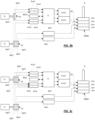
- the left section of the electric drive train depicted on FIG. 1 (comprising the gas turbine or internal combustion engine T, electric generator assembly G, rectifier units, Ru, main bus B, DC/DC converter, RESS and power management system PM) constitutes the backend section of the electric drive train.
- the front-end section of the electric drive train, depicted on the right of FIG. 1 comprises two electric motor assemblies M/R and T/R and their associated redundant controllers Cont1, Cont2.
- Those controllers convert the DC into the AC waveform necessary to drive the electric motor assemblies' M/R and T/R.
- one electric motor assembly, M/R (on the top) is dedicated to driving the main rotor, R and the accessories ACC such as hydraulic pumps, cooling pumps etc... whereas the other electric motor assembly T/R (on the bottom) drives the tail rotor Tr.
- the tail rotor controller Cont2 may be directly connected to the RESS in order to maintain yaw control during autorotation, in the case of a turbine failure.
- the energy stored into the RESS can be combined with the energy produced by the electric generator assembly G during flight phases requiring high power demand (such as takeoff and climb), resulting in appreciable downsizing of the gas turbine or internal combustion engine T. Additionally, the RESS provides a valuable failure backup in case of electric generator assembly G, or engine T failure, resulting in a considerably safer operation than conventional mechanical drive trains.
- the potential of series-hybrid topologies in aviation is considerable, considering the significant gains in safety and performance.
- a multi-stack topology is disclosed by the same inventor, Pascal Chretien, in the patent documents FR2957207 , US2014248168 , and US2014203739 .
- Those three patents disclose (at system level) an electromagnetic distributed direct drive used in replacement of mechanical gearboxes.
- the inherent performance and safety advantages brought by those multi-stack systems capable of eliminating single point of failure are detailed in those three patents documents.
- the patent document US8026679B2 discloses a hybrid vehicle with a controller used for restraining change in torque output of second rotary electric machine when the controller activates the first rotary electric machine.
- a battery is connected to an electrical path branched off between a matrix converter and a second rotary electric motor.
- An inverter is interposed among the battery.
- the matrix converter and the second rotary electric machine converts alternating current (AC) power to direct current (DC) power and vice versa.
- a controller is for activating a first rotary electric machine with power fed from the battery.
- the controller is used for restraining the change in torque output of the second rotary electric machine when the controller activates the first rotary electric machine.
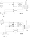
- FIG. 2 is a block diagram depicting conventional series-hybrid electric drive train architecture adapted to a notional four stack electric drive train as disclosed by aforementioned patent documents FR2957207 , US2014248168 , and US2014203739 .
- Only the main rotor drive-train is depicted in this FIG.2 , for sake of simplicity (the tail rotor being a scale model of the main rotor drive, as tail rotors only need to develop a fraction of the power produced by the main rotor).
- the power management system is not depicted in this FIG.2 for sake of simplicity, also.
- a gas turbine or internal combustion engine T drives a multi-stack electric generator assembly G.
- Said electric generator assembly G comprises four independent stacked electric generator elements Eg1, Eg2, Eg3, Eg4. Each stacked electric generator elements Eg1, Eg2, Eg3, Eg4 is connected to its own associated rectifier Ru1, Ru2, Ru3, Ru4 subsequently producing DC that is fed to the main bus B.
- the RESS used for transient power demand and emergency backup (engine failure) is connected to the main bus B.
- the main bus B drives a controller assembly via separate outputs.
- the controller assembly comprises a plurality of physically distinct motor controllers Cont1, Cont2, Cont3, Cont4.
- Those controllers convert the DC into AC waveforms, each one feeding one stacked electric motor element Ee1, Ee2, Ee3, Ee4 of the electric motor assembly GEMD (as disclosed by aforementioned patent documents FR2957207 , US2014248168 , and US2014203739 ), said stacked electric motor elements being connected to the propeller shaft or main rotor R.
- This solution brings some advantages over the architecture depicted in FIG. 1 , as it eliminates most single points of failure, resulting in better end to end reliability (MTBF). The failure of one or several components in the chain will result in lower available power. However, it may not necessitate an emergency landing.
- Series-hybrid topologies present numerous advantages over mechanical drives; one of them being the capacity of operating as a transmission with infinitely variable reduction ratio, enabling to operate the engine (or gas turbine) at its most thermodynamically efficient point.
- Another advantage is the modularity and ease of physical integration: all the components of a series-hybrid drive being interconnected by electrical cables, they can be freely moved across the vehicle without negatively impacting on overall system complexity, as opposed to mechanical drive trains suffering from constraints inherent to shaft, gears and other mechanical parts.
- end-to-end losses of a conventional series-hybrid electric drive train can range from 11% to 13%.
- the direct consequence of those losses is a potentially higher energy requirement (fuel consumption), than a conventional mechanical drive.
- those losses may represent considerable amounts of fuel.
- Running the internal combustion engine or gas turbine T at its most thermodynamically efficient operating point during cruise is known to potentially offset some of those losses.
- real life efficiency improvements are often marginal when compared with modern mechanical drive trains. This efficiency pitfall is a known limitation in aviation where weight and energy efficiency are both paramount.
- twin engine configurations suffer from several drawbacks.
- Conventional twin engine helicopters benefit from statistically significantly decreased likelihood of total power loss, however, both engines are connected to one single mechanical gearbox which cannot be duplicated for redundancy, hence remaining a known single point of failure.
- the failure of one gear belonging to the mechanical drive train leads to a total transmission loss. This fact is illustrated by regular crash reports issued by civil aviation authorities worldwide.
- Another drawback of the conventional twin engine configuration is the fact that each turbine must be sized in such a way to be capable of sustaining a flight in OEI (One Engine Inoperative) condition. This condition must be met to take into consideration the remote possibility of OEI, when in fact most of the aircraft's operational life is conducted using two serviceable engines. In normal operation, each engine is continuously operating at 50% to 70% of its emergency power.
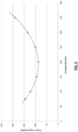
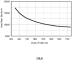
- FIG. 6 depicts the heat rate (which relates to specific fuel consumption) of a notional gas turbine versus its output power.
- FIG. 6 teaches us that the lower the power developed by a gas turbine is, the higher its Specific Fuel Consumption becomes. Therefore, there is a clear advantage to operate the gas turbine at its highest possible power to benefit from optimal fuel consumption. Consequently, twin turbine aircraft are less fuel efficient than singles. Analyzing a twin engine power plant at system level reveals that specific power per unit of weight is lower than in a single engine machine, which negatively impacts the payload.
- Another problem affecting a conventional twin engine aircraft is that two identical turbines must be used, both of which have identical TBO (Time Before Overall) resulting in longer downtime for maintenance and almost a double operating cost. Given this situation, a further aim of the invention is to significantly reduce the physical size and operating costs of electric drive train.
- Transient response is another inherent problem of conventional twin engine solution: when one engine fails, the remaining valid gas turbine that was running at 50% to 70% of its maximum power must increase its power output as quickly as possible in order to compensate for the failed engine. Depending on the Density Altitude, transient power requirement can be difficult to meet without adverse effect, such as possible compressor stall. Conventional turbine can take up to a few seconds to reach their maximum power, hence negatively affecting aircraft's safety and flight envelope. This drawback is particularly preponderant during takeoff: Engine failure during takeoff affects the takeoff profile path and specific takeoff procedures are elaborated for OEI condition.
- Another context where transient engine response during OEI entry can become potentially dangerous is when one engine fails during sling work operation (hover out of ground effect), causing the helicopter to momentarily sink. If a rescuer is on the sling, the situation can become hazardous. Given this situation, another aim of the invention is to improve the safety of electric drive train.
- an electric drive train comprising:
- the disclosed invention intends solving the problems related to the prior art. Moreover, this novel architecture is capable of improving end to end efficiency at power settings commonly applied during significant parts of aircraft's mission profiles (such as during cruise, which usually accounts for most of the fuel consumption), or other propulsion systems as well as electric power generation device belonging to the domains previously mentioned in the technical field of the invention.
- Each stacked electric motor element can be independently supplied by different routes hereinafter defined as power branches, b1 to bn.
- power branches b1 to bn.
- the disclosed architectures combine two different topologies of power branches, thus optimizing efficiency during cruise, as well as maintaining transient power capability, such as during takeoff or aerial work operations (e.g. sling work), or power backup during emergencies.
- FIG. 4 shows the power requirement versus the speed of a medium size notional helicopter in the 1.7 ton range, at three different takeoff weights.
- FIG. 5 shows the power requirement versus the speed of a notional light fix wing aircraft.
- the electric generator which supplies current to the power branch of the first topology is the same electric generator which supplies Alternating Current to the power branch of the second topology, said electric generator is in the form of an electric generator assembly supplying Alternating Current to both power branch of the first topology and power branch of the second topology.
- Said electric generator assembly comprises a plurality of stacked electric generator elements:
- the electric generator which supplies current to the power branch of the first topology may be physically distinct from the electric generator which supplies Alternating Current to the power branch of the second topology.
- the electric generator which supplies Alternating Current to the power branch of the second topology can be an electric generator assembly comprising a plurality of stacked electric generator elements and at least one stacked electric generator element can supply Alternating Current to the power branch of the second topology.
- the electric generator which supplies current to the power branch of the first topology can be an electric generator assembly comprising a plurality of stacked electric generator elements and at least one stacked electric generator element can supply Alternating Current to the power branch of the first topology.
- the power branch of the first topology and the power branch of the second topology may be cross connected at generator level.
- the power branch of the first topology is supplied with Direct Current by the electric generator.
- the power branch of the first topology comprises a rechargeable energy storage system (RESS) configured to enable an electric flight during some phases of a flight domain as well as being capable of meeting a transient power demands or emergency power demands.
- RSS rechargeable energy storage system
- a second aspect of the invention provides an aircraft with an electric drive train comprising:
- a third aspect of the invention provides a method for feeding an electric drive train comprising an electric motor assembly configured to drive a rotor or propeller shaft, said electric motor assembly comprising a plurality of stacked electric motor elements, the method comprising the steps of:
- This method may also comprise the step of adjusting the energy distribution carried by each power branch in function of a flight domain.
- This method may also comprise the step of cross connected the power branches with electrical cross connection at generator level.
- a fourth aspect of the present invention provides an electric drive train including:
- each electric motor element includes a dedicated power supply branch.
- the one or more power sources includes a plurality of electric generator elements.
- each power supply branch is connected to a corresponding electric generator element.
- at least one of the power supply branches is connected to two or more electric generator elements.
- a first subset of the plurality of electric generator elements are stacked together to define a stacked generator assembly and wherein the stacked generator assembly includes a first alternating current (AC) source.
- a second subset of the plurality of electric generator elements are stacked together to define a second stacked generator assembly and wherein the second stacked generator assembly includes a second AC source.
- the system driving the first and/or second AC generator unit/s may include one or more of a Free Piston Engine, internal combustion engine or gas turbine. That is, the first and/or second AC source includes one or more of a Free Piston Engine, internal combustion engine or gas turbine.
- a subset of the electric generator elements are Direct Current (DC) power generators.
- DC Direct Current
- the rechargeable energy storage system is configured to supply power during times of dynamic power demands of a connected load.
- the one or more power sources has a power production capacity and wherein the rechargeable energy storage system is configured to supply additional power during times when the dynamic power demands exceed the power production capacity of the one or more power sources.
- the rechargeable energy storage system is configured to supply power during times of power supply failure.
- the one or more matrix converters modify one or more of a frequency, shape, or duty cycle of the second subset of power signals.
- the electric drive train includes two or more power sources. In some of these embodiments, at least one of the power sources supplies power to at least one power supply branch of both the first and second subsets.
- the plurality of electric motor elements are stacked together to define a stacked electric motor assembly.
- the second subset of power branch distributes a majority of power from the one or more power sources to the electric motor elements when power demands fall within a predetermined power range.
- an aircraft having a rotor or propeller shaft and an electric drive train according to any one of the preceding claims, wherein the rotor or propeller shaft are driven by the plurality of stacked electric motor elements.
- the first subset of power supply branches exclusively distributes power to the electric motors elements during any part of the flight domain and during power source failure of the aircraft.
- a distribution of power carried by each subset of the power supply branches is a function of a flight domain.
- a method of distributing power from one or more power sources to an electric motor assembly including a plurality of stacked electric motor elements, the method including:
- step (ii) includes selectively adjusting the distribution of power transmitted along each path based on operating demands of the electric motor assembly.
- a seventh aspect of the present invention there is provided a method of feeding an electric drive train according to the fourth aspect, the method including the steps of:
- Embodiments of the disclosure may be described herein in terms of functional and/or logical block components and various processing steps. It should be appreciated that such block components may be realized by any number of hardware, software, and/or firmware components configured to perform the specified functions.
- conventional techniques and components specifically related to gas turbine or internal combustion engines, free piston engine, electric generators, rectifiers, converters, main bus, power management system, DC/DC converter, Rechargeable Energy Storage System RESS, controller assembly, controllers, rotor or propeller shaft and electric motors may not be described in detail herein, the specification being limited to system level.
- embodiments of the present disclosure may be practiced in conjunction with a variety of structural bodies, and that the embodiments described herein are merely example embodiments of the disclosure.
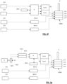
- FIG. 3 presents a series-hybrid electric drive train architecture in accordance with an illustrative embodiment of the invention where a single engine T is used to power the notional four-stack electric motor assembly hereinafter referred as GEMD.
- This disclosed architecture uses the same multi-stack electric motor assembly GEMD and multi-stack electric generator assembly G as depicted in FIG. 2 .
- the combination of the engine T and generator assembly G collectively represents a power source for the electric drive train.
- a single engine T is used to power the electric motor assembly GEMD.
- a symmetrical four stack topology is used. It comprises the four stack electric generator assembly G as well as the four stack motor assembly GEMD.
- each motor element constituting the stack can be independently supplied by its dedicated controller assembly.
- Different topologies can be used:
- Each stacked electric motor element Ee1, Ee2, Ee3 and Ee4 of the electric motor assembly GEMD can be independently supplied by different routes or paths hereinafter defined as “power branches” or “power supply branches", labelled as b1, b2, b3, b4.
- a power branch is defined by electrical connections and subsystems between a power source and the motor assembly.
- the power source engine T and notional generator assembly G
- the disclosed architectures combine two different topologies of power branches, enabling optimized efficiency during cruise, as well as maintaining transient power capability, such as during takeoff or aerial work operations (e.g. sling work).
- the total power delivered to the common shaft R by the whole assembly of motor elements Ee1, Ee2, Ee3 and Ee4 is the sum of the powers delivered by each power branch to its associated motor element (not taking into account energy losses in the motor Elements).
- the balancing process of the power delivered by each branch can be linear and proportional to the power demand, or it can be in the form of a discrete switching process between one branch to another branch, depending on the type of operation or flight domain.
- the disclosed architecture maintains the advantages specific to series-hybrid topologies, the battery bank RESS being capable of supplying energy during transient power demands, as well as providing backup in the case of engine failure.
- the electric motor assembly GEMD drives a rotor or a propeller shaft R in rotation.
- the rotor could be the main rotor or the tail rotor of a rotary wing aircraft.
- the propeller shaft R could be that of a fix wing aircraft, a car, a motorbike, motorcycle, an armored vehicle or could drive the propeller of a boat, jet-ski, torpedo, submarine, etc.
- the electric generator assembly G and the electric motor assembly GEMD are disclosed by patent documents FR2957207 , US2014248168 , US2014203739 and WO2016030168 which are hereby enclosed for reference.
- the common electric generator assembly G comprises a plurality (four in the example) of stacked electric generator elements Eg1, Eeg2, Eg3 and Eg4.
- the electric motor assembly GEMD also comprises a plurality (four in the example) of stacked electric motor elements Ee1, Ee2, Ee3 and Ee4.
- Each of the stacked generator elements Eg1, Eeg2, Eg3 and Eg4 is a single or polyphase AC generator.
- each of the stacked generator elements Eg1, Eg2, Eg3 and Eg4 could be a three-phase AC generator.
- Each stacked electric generator element Eg1, Eg2, Eg3, Eg4 of the electric generator assembly G comprises a rotor driven by the common shaft and a stator composed of windings and magnetic circuits.
- each stacked electric motor element Ee1, Ee2, Ee3, Ee4 of the electric motor assembly GEMD comprises a rotor driving the common(s) shaft(s) R and a stator composed of windings and magnetic circuits.
- Each stacked electric motor element Ee1, Ee2, Ee3, Ee4, and each stacked electric generator element Eg1, Eg2, Eg3, Eg4, is mechanically isolated from the adjacent stacks in order to prevent fire and faults propagations.
- the electric drive train is split into two pairs of power branches:
- Each top power branch b1, b2 may comprise a rectifier Ru1, Ru2 which is connected between the respective stacked electric generator element Eg1, Eg2 of the electric generator assembly G and the common main bus B.
- the RESS is connected onto the common main bus B through a direct line, or via a bidirectional DC/DC converter, if required.
- Each of the top branches b1, b2 also comprises a separate motor controller Cont1, Cont2 independently fed by the main bus B.
- Each controller Cont1, Cont2 independently feeds one stacked electric motor element Ee1, Ee2 of the electric motor assembly GEMD.
- energy is transferred via the two top branches b1, b2, from the two-stack electric generator elements Eg1 and Eg2 of the electric generator assembly G to two-stack electric motor elements Ee1, Ee2 of the electric motor assembly GEMD.
- the engine T drives the electric generator assembly G.
- This engine T can be a gas turbine or an internal combustion engine (such as, but not limiting to turboshaft engine or a piston engine, such as a Free Piston Engine FPE).
- the stacked electric generator elements Eg1, Eg2, Eg3 and Eg4 of the electric generator assembly G are driven by a common shaft connected to the engine T.
- the electric generator assembly G is an external unit located outside the engine T.
- fully integrated solutions in which the multi-stack electric generator assembly G is integrated inside the engine T are also possible.
- Such integrated solution presents obvious weight advantages, in the case of a gas turbine, for example, as the multi-stack electric generator assembly G can be driven at high speed directly out of the shaft that has a speed of 40,000 RPM (Rotation Per Minute) or more. Integrating the multi-stack electric generator assembly G inside the gas turbine or internal combustion engine T saves the weight of the primary reduction gearbox which usually comes with all turboshaft engines that have a standard output shaft speed around 6,000 RPM. Moreover, high speed generators bring significant power to weight advantages. Several generator technologies are possible, such as permanent magnets, or switched reluctance. Permanent magnets offer significant weight gains and are often the preferred option. Generator's magnetic topology can be axial flux, radial flux, transverse flux or any other configurations.
- the power produced by the batteries is combined, at the main bus level, with the power delivered by the gas turbine or internal combustion engine T.
- the RESS capacity can be dimensioned in such manner that full electric flight is possible for a few minutes.
- This configuration presents some obvious advantages such as better takeoff performances, and/or significant safety improvement since en engine failure does not impact the safety: the craft can land safely on electric power.
- new mission profiles can be achieved, such as silent flight and zero infrared signature flight.
- Another advantage is the capacity of active rotor or propeller shaft R speed regulation. This capability is important during particular phases of the flight domain where the rotor or the propeller speed tends to increase as a result of aggressive flight maneuvers.
- the multi-stack drive motor assembly GEMD acts as an inductive brake in order to prevent rotor or propeller shaft R from overspeeding.
- at least one of the top power branchesb1 and/or b2 is capable of enabling regenerative braking in order to provide active regulation of rotor or propeller shaft speed.
- the energy generated during the braking operation can be fed back into the RESS, or into a dummy load.
- Active rotor RPM control leads to improved helicopter maneuverability, conferring a marked tactical advantage on modern battlefield.
- the bottom branches b3 and b4 can also be used to provide regenerative breaking by feeding the excess power into a dummy load.
- Each bottom power branch b3 and b4 is feeding the respective stacked electric motor element Ee3 and Ee4 of the electric motor assembly GEMD.
- the electric generator assembly G supplies AC to each bottom power branch b3, b4. More specifically, the AC produced by the stacked electric generator elements Eg3 and Eg4 of the electric generator assembly G is feeding the respective bottom power branches b3 and b4.
- a matrix converter is a multi-port energy conversion device that comprises power switching circuitry capable of generating, from the high frequency AC produced by the electric generator assembly G, the AC signals required to drive the respective electric motor element Ee3, Ee4.
- Matrix converters also include one or several signal processor(s) capable of driving the internal power switching circuitry in order to generate and synchronize the waveform required to feed the windings inside each stacked electric motor element Ee3, Ee4 of the electric motor assembly GEMD.
- the matrix converter configuration is several percent more efficient than a conventional series-hybrid chain such as those used by the top power branches b1, b2.
- a conventional series-hybrid chain such as those used by the top power branches b1, b2.
- Better results can be achieved when the matrix converter is optimized around a given power setting (e.g. power for cruise speed). It may by apparent to those skilled in the art that several percent represents considerable fuel savings over the aircraft's service life and brings the overall system efficiency to a level comparable to a multistage gearbox.
- the drastic reduction of components and subsystems leads to better reliability and lighter assemblies. Due to their inherent efficiency, matrix converters Mc3, Mc4 require little cooling, therefore resulting in lower system weight.
- the matrix converters Mc3 and Mc4 could be direct matrix converters (AC-AC) of a topology such as depicted in FIG. 7 .
- the inputs i a3 , i b3 , i c3 of the matrix converter Mc3 are each connected to one of the three phases of the electric generator element Eg3.
- the outputs O a3 , O b3 , O c3 of the matrix converter Mc3 are each connected to one of the three phases of the electric motor element Ee3.
- the inputs i a4 , i b4 , i c4 of the matrix converter Mc4 are each connected to one of the three phases of the electric generator element Eg4.
- the outputs O a4 , O b4 , O c4 of the matrix converter Mc4 are each connected to one of the three phases of the electric motor element Ee4.
- the matrix converters Mc3 and Mc4 are indirect matrix converters (AC-DC/DC-AC) with a DC-link.
- Other configurations are possible, for example with a direct matrix converter Mc3 in the bottom power branch b3, and an indirect matrix converter Mc4 in the bottom power branch b4. Or vice versa.
- Multiphase solutions (6 phases or more) are also possible in order to improve system reliability.
- the power distribution between the different branches b1, b2, b3 and b4 can be either linear or discrete.
- the energy stored in the RESS is used to meet transient power demand.
- the RESS supplies current to the top power branch b1 and/or b2 in addition to the electric generator assembly G.
- the RESS is capable of meeting emergency power demand.
- the RESS can supply the power required to maintain straight and level flight during the time required to restart the engine T and/or reset the electric generator assembly G.
- Power distribution control along the different power branches is performed by a processor unit (not depicted in the figures, for sake of clarity) that takes into account a multitude of parameters and physical values, such as (but not limited to) shaft power requirement, flight controls settings, generator status, system integrity and system health, as well as environmental parameters such as Outside Air Temperature (OAT), pressure altitude.
- the processor unit can be a dual channel redundant unit with built in real time integrity control system.
- stacked electric motor elements Ee3 and Ee4 will need to carry significant power during extended period of the flight, hence requiring a different physical configuration and a different cooling system than stacked electric motor elements Ee1 and Ee2.
- a conical configuration refers to a stack where the various electric motor elements Ee1, Ee2, Ee3, Ee4 are not all rated to the same continuous power, whereas a cylindrical configuration refers to a stack of electric motor elements all rated to the same power.
- electric generator assembly G having different number of stacks and electric motor assembly GEMD using different number of motor elements.
- the electric generator assembly G could comprise only two-stack generator elements.
- the electric motor assembly GEMD could also comprise only two-stack electric motor elements each one fed by his own power branch.
- the number of stacked electric motor elements Ee1, Ee2, Ee3, Ee4 can be different from the number of electric generator stacks Eg1, Eeg2, Eg3, Eg4.
- a single top power branch b1 or b2 can feed a single electric motor element Ee1 or Ee2.
- a single bottom power branch b3 or b4 can feed a single electric motor element Ee3 or Ee4.
- a single electric generator element Eg1 or Eg2 can supply AC to a single top power branch b1 or b2. Or the two-stack electric generator elements Eg1 and Eg2 can be used to feed a single top power branch b1 or b2. Conversely, a single-stack electric generator element Eg3 or Eg4 can supply AC to a single bottom power branch b3 or b4. Or the two-stack electric generator elements Eg3 and Eg4 can be used to feed a single bottom power branch b3 or b4.
- Auxiliary Power Unit APU
- a light DC/DC converter can be used to lower the RESS voltage down to the avionics' voltage resulting is significant weight savings (the turbine section of a 90 KW APU for a medium size helicopter is around 65 Kg to 80 Kg, to which the generator must be added).
- the disclosed invention can advantageously be applied to two twin engine aircrafts.
- the drawbacks inherent to conventional twin engine aircrafts have been previously exposed. Applying the disclosed architecture to the twin engine configuration improves both performances and safety during OEI transition as the RESS eliminates transient power lag. Additionally, significant economical advantages are brought by the disclosed configuration.
- FIG. 3a presents a series-hybrid electric drive train architecture in accordance with another illustrative embodiment of the invention.
- This disclosed architecture uses the same multi-stack electric motor assembly GEMD as depicted in FIG. 2 and FIG. 3 and provides the same benefits and advantages of those depicted above in reference to said FIG. 3 .
- Two physically distinct engines T1 and T2 are used to power the notional four-stack drive GEMD, via the two completely independent pairs of power branches, b1-b2 and b3-b4. Each pair of power branches uses a different topology.
- the top engine T1 drives the electric generator assembly G1 and the bottom engine T2 drives the electric generator assembly G2.
- the electric generator assemblies G1 and G2 are physically distinct.
- the engines T1 and T2 are similar to the engine T described in reference to first embodiment.
- the generator assemblies G1 and G2 are similar to the generator assembly G described above in reference to first embodiment. The only difference being that the generator assembly G2 is a two-stack generator comprising two stacked electric generator elements Eg23 and Eg24.
- the four stack electric generator assembly G1 mounted on the top engine T1 feeds the top power branches b1 and b2 and subsequently the stacked electric motor elements Ee1 and Ee2 of the electric motor assembly GEMD, via a conventional series-hybrid topology. More specifically, the AC produced by the stacked electric generator element Eg11, Eg12, Eg13 and Eg14 is converted into DC by using rectifier units Ru11, Ru12, Ru21, Ru22 similar to the rectifier units Ru1, Ru2 described above.
- each rectifier unit Ru11, Ru12, Ru21, Ru22 is paralleled onto the DC main bus B, which separately feeds each controller Cont1, Cont2 driving the associated stacked electric motor elements Ee1, Ee2 of the multi-stack drive motor assembly GEMD.
- the controller's assemblies can either be located outside the multi-stack drive motor assembly GEMD, or integrated inside said multi-stack drive motor assembly. If required, a two-ways DC/DC converter (such as shown in FIG. 1 ) can be used in between the main bus B and the RESS in order to match battery and main bus voltages and/or provide more efficient battery usage (not shown, for the sake of simplicity).
- FIG. 3a depicts a topology where a four-stack electric generator assembly G1 is driven by the top engine T1 and a two stack electric generator assembly G2 is driven by the bottom engine T2, along with a four-stack electric motor assembly GEMD; however, electric generators assemblies G1, G2 and electric motor assembly GEMD using different number of stacks are possible.
- the electric generator assembly G1 could comprise only a two-stack electric generator.
- a single top power branch b1 or b2 can feed a single electric motor element Ee1 or Ee2.
- a single bottom power branch b3 or b4 can feed a single electric motor element Ee3 or Ee4.
- a single electric generator element Eg11, Eg12, Eg13 or Eg14 can supply AC to a single top power branch b1 or b2. Or all the four stacked electric generator elements Eg11, Eg12, Eg13 and Eg14 can be used to feed a single top power branch b1 or b2.
- a single electric generator element Eg23 or Eg24 can supply AC to a single bottom power branch b3 and/or b4. Or all the two stacked electric generator elements Eg23 and Eg24 can be used to feed a single bottom power branch b3, or b4.
- the top engine T1 and the bottom engine T2 can be rated to the same maximum power (identical engines), or can have different sizes, depending on the Maximum continuous power requirement of the envisioned mission profile.
- the bottom engine T2 can be an engine rated at to a higher power than the top engine T1 (larger size engine), in order to provide the power necessary during cruise. In this configuration, the bottom engine T2 can operate near to its maximum power output, where its specific fuel consumption is the lowest (refer to FIG. 6 ).
- the top engine T1 can be shut down during cruise in view of operating at the lowest burn rate. In case of failure of the bottom engine T2, the RESS can supply the power required to maintain straight and level flight during the time required to restart the top engine T1.
- the top engine T1 may be dimensioned in such a way to produce the power corresponding to the best endurance speed. Thus, one engine can be switched off during certain part of the flight domain such as during cruise.
- One drawback of this configuration is the impossibility to recharge the RESS during flight once the top engine T1 is shut down (as the energy stored in the RESS can be used during short climbs or transient power demands).
- the engines T1 and T2 can be of different nature; for instance, the top engine T1 can be a gas turbine, whereas the bottom engine T2 can be a piston engine for better fuel efficiency during cruise. Reverse configurations are also possible to match specific mission profiles.
- the electric generator assemblies G1 and G2 are similar to the electric generator assemblies G1 and G2 described above in reference to second embodiment, the only difference being that the electric generator assembly G1 is a two-stack generator comprising two stacked electric generator elements Eg11 and Eg12, and that the electric generator assembly G2 is a four-stack generator comprising four stacked electric generator elements Eg21, Eg22, Eg23 and Eg24.
- the top engine T1 drives the two stack electric generator assembly G1 connected to two rectifiers Ru11 and Ru12 of a conventional series-hybrid configuration, subsequently feeding the stacked electric motor elements Ee1 and Ee2 of the multi-stack drive GEMD as described above in reference to FIG. 3a .
- the bottom engine T2 drives the four-stack electric generator assembly G2, of which the two stacks Eg23 and Eg24 are respectively connected to the matrix converter Mc3 and Mc4 feeding the stacked electric motor elements Ee3 and Ee4 of the electric motor assembly GEMD as described above.
- each one of the two remaining stacks Eg21 and Eg22 of the electric generator assembly G2 is respectively cross connected to the input of a rectifier Ru21 and Ru22 feeding to the conventional series-hybrid top power branches b1 and b2.
- the drive train comprises various power branches with electrical cross connection at generator level (at front end level).
- the cross connection enables one engine (T2) to simultaneously feed both pairs of branches b1-b2 and b3-b4.
- One direct advantage of this configuration is to thermally unload stacked electric motor elements Ee3 and Ee4 of the electric motor assembly GEMD during high power cruise. For instance:
- the power balancing process between the different pairs of power branches b1-b2, and b3-b4 can use other distribution ratios to optimize the efficiency in function of the thermal limits of the stacked electric motor elements Ee1, Ee2, Ee3, Ee4 of the electric motor assembly GEMD and flight domain.
- the bottom engine T2 can be rated to a higher power than the top engine T1, and can therefore be solely used during cruise at its most thermodynamically efficient operating point, whilst the top engine T1 may be shut down.
- the front end cross connection enables recharging the RESS which energy that can be used during climbs or various manoeuvres requiring transient power, without needing to restart the top engine T1. This solution combines the efficiency advantages of the matrix converter with the flexibility of conventional series-hybrid topologies.
- the engines T1 and T2 can be dissimilar engines, in which the top engine T1, in addition of being lighter and smaller than the bottom engine T2, operates at a considerably lower duty cycle than the bottom engine T2, thus leading to reduced maintenance and lowered operating cost.
- the disclosed invention When applied to a twin-engine configuration, the disclosed invention presents significant performance and safety improvements where cross feeding combined with the RESS enable OEI operation without incurring transient power losses. Moreover, the disclosed architectures bring substantial economical advantages over conventional twin engine configuration by enabling single engine cruise, on one engine (T2) operating at its best SFC, hence optimized fuel burn. In an improved configuration, both cruise (T2) and supplementary engine (T1) can be of different sizes and rated at different power; with both of them operating during the takeoff and landing phases, whereas only one engine (T2) operates during cruise.
- FIG. 3b depicts a topology whereby a two-stack electric generator assembly G1 is driven by the top engine T1 and a four stack electric generator assembly G2 is driven by the bottom engine T2, along with a four-stack drive GEMD; however electric generators assemblies G1 and/or G2 and electric motor assembly GEMD using different number of stacks are possible.
- a single top power branch b1 or b2 can feed a single electric motor element Ee1 or Ee2.
- a single bottom power branch b3 or b4 can feed a single electric motor element Ee3 or Ee4.
- a single electric generator element Eg11 or Eg12 can supply AC to a single top power branch b1 or b2.
- FIG. 3c presents a series-hybrid electric drive train architecture in accordance with yet another illustrative embodiment of the invention.
- This disclosed architecture uses the same notional multi-stack electric motor assembly GEMD as depicted in FIG. 2 , FIG. 3 , FIG. 3a and FIG. 3b and provides the same benefits and advantages of those depicted above in reference to said FIG. 3, FIG. 3a and FIG. 3b .
- the two physically distinct engines T1 and T2 are used to power the four-stack drive GEMD via the two pairs of power branches, b1-b2 and b3-b4, respectively.
- the engines T1 and T2 are similar to the engines T1 and T2 described above in reference to second and third embodiments.
- the electric generator assemblies G1 and G2 are physically distinct and are similar to the electric generator assembly G described above in reference to first embodiment. Accordingly, engines T1 and T2 are both driving four stack electric generators assemblies G1 and G2.
- the four-stack electric generator assembly G1 mounted on the top engine T1 feeds the top power branches b1, b2 and subsequently the stacked electric motor elements Ee1 and Ee2 of the electric motor assembly GEMD, via a conventional series-hybrid topology as described above in reference to FIG. 3a and FIG. 3b .
- top engine T1 and bottom engine T2 may be preferably rated to the same power, although configurations using dissimilar engines such as detailed in FIG. 3b are also possible.
- FIG. 3c depicts a topology where a four-stack electric generator assembly G1 is driven by the top engine T1 and a four stack electric generator assembly G2 is driven by the bottom engine T2, along with a four-stack drive GEMD; however electric generators assemblies G1 and/or G2 and electric motor assembly GEMD using different number of stacks are possible.
- a single power branch b1 or b2 can feed only one stacked electric motor element Ee1 or Ee2.
- a single bottom power branch b3 or b4 can feed a single electric motor element Ee3 or Ee4.
- a single electric generator element Eg11, Eg12, Eg13 or Eg14 can supply AC to a single top power branch b1 or b2.
- a single electric generator element Eg21, Eg22, Eg23 or Eg24 can supply AC to a single bottom power branch b3 or b4.
- all the four stacked electric generator elements Eg21, Eg22, Eg23 and Eg24 can be used to feed a single bottom power branch b3 or b4.
- FIG. 3d presents a series-hybrid electric drive train architecture in accordance with yet another illustrative embodiment of the invention.
- This disclosed architecture uses the same notional multi-stack electric motor assembly GEMD as depicted in FIG. 2 , FIG. 3 , FIG. 3a , FIG. 3b and FIG. 3c and provides the same benefits and advantages of those depicted above in reference to said FIG. 3, FIG. 3a , FIG. 3b and FIG. 3c .
- the engine T2 drives the electric generator assembly G2.
- the engine T2 and the electric generator assembly G2 are similar to those described above in reference to second embodiment.
- the generators G11, G12 and electric generator assembly G2 are physically distinct.
- the electric generators G11 and G12 supply DC to the top power branches b1 and b2. They are preferably selected (but not limiting to) from the following list: fuel cell, photovoltaic cells (or solar panels), magnetohydrodynamic generator, radio-isotopic generator, thermo-electric or electrochemical generator, beta cells battery. This topology may become advantageous when G11 and G12 use fuel cells, subsequently reducing carbon footprint, and drastically lowering infrared and acoustic signatures (when compared with engines T and T1 describe above).
- the DC generators G11 and G12 feed the top power branches b1 and b2 and subsequently the stacked electric motor elements Ee1 and Ee2 of the electric motor assembly GEMD, via a series-hybrid topology. More specifically, the DC produced by the generators G11 and G12 is paralleled onto the DC main bus B, which separately feeds each controller Cont1, Cont2 driving the associated stacked electric motor elements Ee1, Ee2 of the multi-stack drive motor assembly GEMD.
- the controller's assemblies can either be located outside the multi-stack drive motor assembly GEMD, or integrated inside said multi-stack drive motor assembly GEMD. If required, a two-ways DC/DC converter (such as shown in FIG.
- FIG. 3d depicts a topology whereby a two-stack electric generator G2 is used on the bottom engine T2 along with a four-stack drive GEMD; however electric generator assembly G2 and electric motor assembly GEMD using different number of stacks are possible.
- a single electric generator G11 or G12 can be used to feed the top power branches b1 and b2. Or all the two electric generators G11 and G12 can be used to feed a single top power branch b1 or b2. Or, a single electric generator G11 or G12 can be used to feed a single top power branch b1 or b2.
- a single bottom power branch b3 or b4 can feed a single electric motor element Ee3 or Ee4.
- a single electric generator element Eg23 or Eg24 can supply current to a single bottom power branch b3 or b4. Or all the two stacked electric generator elements Eg23 and Eg24 can be used to feed a single bottom power branch b3 or b4.
- FIG. 3e presents a series-hybrid electric drive train architecture in accordance with yet another illustrative embodiment of the invention.
- This disclosed architecture uses the same notional multi-stack electric motor assembly GEMD as depicted in FIG. 2 , FIG. 3 , FIG. 3a , FIG. 3b , FIG. 3c and FIG. 3d and provides the same benefits and advantages of those depicted above in reference to said FIG. 3, FIG. 3a , FIG. 3b, FIG. 3c and FIG. 3d .
- Two DC generators G11, G12 and one engine T2 are used to power the four-stack drive GEMD, via the two pairs of power branches, b1-b2 and b3-b4, respectively.
- the engine T2 drives the electric generator assembly G2.
- the DC generators G11 and G12 are similar to those described above in reference to the fifth embodiment.
- the engine T2 and the electric generator assembly G2 are similar to those described above in reference to the third or fourth embodiments.
- the electric generators G11, G12 and the electric generator assembly G2 are physically distinct.
- the DC generators G11 and G12 feed the top power branches b1 and b2 and subsequently the stacked electric motor elements Ee1 and Ee2 of the electric motor assembly GEMD, via a series-hybrid topology described above in reference to FIG. 3d .
- the bottom engine T2 drives the four-stack electric generator assembly G2, of which two stacks Eg23 and Eg24 are connected to the matrix converter Mc3 and Mc4 respectively, thus feeding the stacked electric motor elements Ee3 and Ee4 of the electric motor assembly GEMD as described above in reference to FIG. 3b and 3c .
- Each one of the two remaining stacks Eg21 and Eg22 of the electric generator assembly G2 is cross connected at front-end level to the top power branches b1 and b2, via the rectifiers Ru21 and Ru22 respectively, as described above in reference to FIG. 3b .
- This cross-feed topology enables better load sharing and higher power density.
- FIG. 3e depicts a topology whereby a four-stack electric generator assembly G2 is driven by the bottom engine T2, along with a four-stack drive GEMD; however, electric generator assembly G2 and electric motor assembly GEMD using different number of stacks are possible.
- a single electric generator G11 or G12 can be used to feed the top power branches b1 and b2.
- both electric generators G11 and G12 can be used to feed a single top power branch b1 or b2.
- a single electric generator G11 or G12 can be used to feed a single top power branch b1 or b2.
- a single electric generator element Eg21, Eg22, Eg23 or Eg24 can supply AC to a single bottom power branch b3 or b4.
- all the four-stack electric generator elements Eg21, Eg22, Eg23 and Eg24 can be used to feed a single bottom power branch b3 or b4.
- FIG. 3f depicts an electric drive train architecture in accordance with yet another illustrative embodiment of the invention.
- This disclosed architecture uses the same notional multi-stack electric motor assembly GEMD as depicted in FIG. 2 , FIG. 3 , FIG. 3a , FIG. 3b , FIG. 3c , FIG. 3d and FIG. 3e .
- DC generators G11, G12, G21, G22 are used to power the four-stack drive GEMD, via the two independent pairs of power branches, respectively b1-b2 and b3-b4.
- the DC generators G11, G12, G21 and G22 could be physically distinct and are similar to those described above in reference to the fifth and sixth embodiments. They are preferably selected (but not limiting to) from the following list: fuel cell, photovoltaic cells (or solar panels), magnetohydrodynamic generator, radio-isotopic generator, thermo-electric or electrochemical generator, beta cells battery. This topology may become advantageous when G11, G12, G21 G22 use fuel cells, resulting to exceptional thermodynamic efficiency, low or zero carbon footprint, silent operation along with zero infrared signature.
- the bottom electric generators G21 and G22 supply DC to the bottom power branches b3 and b4, respectively.
- the electric generators G11 and G12 feed the top power branches b1 and b2 and subsequently the stacked electric motor elements Ee1 and Ee2 of the electric motor assembly GEMD, via a series-hybrid topology described above in reference to FIG. 3d and FIG. 3e .
- Each one of the bottom electric generators G21 and G22 feeds the stacked electric motor element Ee3 and Ee4 of the electric motor assembly GEMD, via two independent motor controllers Motc3 and Motc4.
- Those motor controllers Motc3, Motc4 convert the DC supplied by the bottom electric generators G21 and G22 to bottom power branches b3 and b4 into the AC waveform required to feed the stator windings of stacked electric motor elements Ee3 and Ee4.
- Each motor controller Motc3, Motc4 converts the DC supply voltage provided by electric generators G21 and G22 to variable frequency output and controls output current flow.
- Pulse width modulation (PWM) control is an example of a control method used by the motor controllers Motc3 and Motc4 for driving the motor elements Ee3 and Ee4. More specifically, the motor controllers Motc3, Motc4 comprise power switching circuitry capable of generating, from the DC coming from the electric generators G21, G22, the AC signals required to drive the respective electric motor element Ee3, Ee4. The motor controllers Motc3, Motc4 also include one or several signal processor(s) capable of driving the internal power switching circuitry in order to generate the waveform required to feed the windings of each stacked electric motor element Ee3, Ee4.
- FIG. 9 depicts the topology of the power switching circuitry of a motor controller which may be employed in the electric drive train architecture according to FIG. 3f .
- the inputs i a3 and i b3 of the motor controller Motc3 are connected to the electric generator G21.
- the outputs O a3 , O b3 , O c3 of the motor controller Motc3 are each connected to one of the three phases of the stacked electric motor element Ee3. Multiphase solutions (6 phases or more are also possible in order to improve system reliability).
- the inputs i a4 and i b4 of the motor controller Motc4 are connected to the electric generator G22; the outputs O a4 , O b4 , O c4 of the motor controller Motc4 are each connected to one of the three phases of stacked the electric motor element Ee4.
- FIG. 3f depicts a topology where a four-stack drive GEMD is used; however, an electric motor assembly GEMD using different number of stacks are possible.
- two electric generators G11, G12 are used to supply DC to the top power branches b1 and b2. Only one electric generator G11 or G12 can be used to feed the top power branches b1 and b2. Or both electric generators G11 and G12 can be used to feed a single top power branch b1 or b2. Or, a single electric generator G11 or G12 can be used to feed a single top power branch b1 or b2. Also, two electric generators G21, G22 are used to supply DC to the bottom power branches b3 and b4.
- Only one electric generator G21 or G22 can be used to feed the bottom power branches b3 and b4. Or both electric generators G21 and G22 can be used to feed a single bottom power branch b3 or b4. Or, a single electric generator G21 or G22 can be used to feed a single bottom power branch b3 or b4.
- FIG. 3g presents a series-hybrid electric drive train architecture in accordance with yet another illustrative embodiment of the invention.
- This disclosed architecture uses the same multi-stack electric motor assembly GEMD as depicted in FIG. 2 , FIG. 3 , FIG. 3a , FIG. 3b , FIG. 3c , FIG. 3d , FIG. 3e and FIG. 3f and provides the same benefits and advantages of those depicted above in reference to said FIG. 3, FIG. 3a , FIG. 3b, FIG. 3c , FIG. 3d, FIG. 3e and FIG. 3f .
- An engine T1 and two DC generators G21, G22 are used to feed the four-stack drive GEMD, via the two completely independent pairs of power branches, respectively b1-b2 and b3-b4.
- the engine T1 drives the electric generator assembly G1.
- the DC generators G21 and G22 are similar to those describe above in reference to the seventh embodiment.
- the engine T1 and the electric generator assembly G1 are similar to those described above in reference to the third embodiment.
- the electric generator assembly G1, and the electric generator G21, G22 are physically distinct.
- the two-stack electric generator assembly G1 driven by the top engine T1 feeds the top power branches b1 and b2 and subsequently the stacked electric motor elements Ee1 and Ee2 of the electric motor assembly GEMD, via the conventional series-hybrid topology depicted above in reference to FIG. 3b .
- the DC generators G21 and G22 feed the bottom power branches b3 and b4 and subsequently the stacked electric motor elements Ee3 and Ee4 of the electric motor assembly GEMD, via a topology comprising two independent motor controllers Motc3 and Motc4, as described above in reference to FIG. 3f and FIG. 9 .
- FIG. 3g depicts a topology where a four-stack drive GEMD is used; however, an electric motor assembly GEMD using different number of stacks is possible.
- two electric generators G21, G22 are used to supply DC to the bottom power branches b3 and b4.
- a single electric generator G21 or G22 can be used to feed the bottom power branches b3 and b4.
- both electric generators G21 and G22 can be used to feed a single bottom power branch b3 or b4.
- a single electric generator G21 or G22 can be used to feed a single bottom power branch b3 or b4.
- a two-stack generator assembly G1 is driven by the top engine T1.
- a single top power branch b1 or b2 can feed a single electric motor element Ee1 or Ee2.
- a single electric generator element Eg11 or Eg12 can supply AC to a single top power branch b1 or b2.
- both stacked electric generator elements Eg11 and Eg12 can be used to feed a single top power branch b1 or b2.
Landscapes
- Engineering & Computer Science (AREA)
- Power Engineering (AREA)
- Mechanical Engineering (AREA)
- Transportation (AREA)
- Combustion & Propulsion (AREA)
- Chemical & Material Sciences (AREA)
- Sustainable Energy (AREA)
- Life Sciences & Earth Sciences (AREA)
- Sustainable Development (AREA)
- Electric Propulsion And Braking For Vehicles (AREA)
- Control Of Eletrric Generators (AREA)
- Control Of Multiple Motors (AREA)
- Train Traffic Observation, Control, And Security (AREA)
Claims (20)
- Elektrischer Antriebsstrang, umfassend:eine oder mehrere Stromquellen (G, G1, G2), die gemeinsam mindestens zwei Stromsignale bereitstellen;eine Elektromotorbaugruppe (GEMD), die eine Vielzahl unabhängig voneinander angetriebener Elektromotorelemente (Ee1, Ee2, Ee3, Ee4) umfasst;wobei jedes Motorelement einen Rotor und einen Stator umfasst;ein Stromverteilungssystem zum Verteilen von elektrischer Energie von einer oder mehreren Stromquellen (G, G1, G2) an die Elektromotorbaugruppe (GEMD), wobei das Stromverteilungssystem eine Vielzahl unabhängiger Stromversorgungszweige (b1, b2, b3, b4) umfasst, wobei jeder Zweig (b1, b2, b3, b4) so konfiguriert ist, dass er ein unabhängiges Stromsignal von einer oder mehreren Stromquellen (G, G1, G2) an mindestens eines der unabhängig mit Strom versorgten Elektromotorelemente (Ee1, Ee2, Ee3, Ee4) überträgt, so dass jedes Elektromotorelement (Ee1, Ee2, Ee3, Ee4) unabhängig von einem Stromversorgungszweig (b1, b2, b3, b4) versorgt wird, wobei;eine erste Teilmenge der Stromversorgungszweige (b1, b2), die dazu konfiguriert ist, eine erste Teilmenge der Elektromotorelemente (Ee1, Ee2) mit einer ersten Teilmenge der Stromsignale zu versorgen, wobei die erste Teilmenge der Stromversorgungszweige (b1, b2) einen oder mehrere Motorregler (Cont1, Cont2) zum Steuern der ersten Teilmenge der Elektromotorelemente (Ee1, Ee2) und ein wiederaufladbares Energiespeichersystem (RESS) umfasst, das dazu konfiguriert ist, Energie der ersten Teilmenge der Stromsignale als gespeicherte Energie zu speichern und die gespeicherte Energie selektiv an den einen oder die mehreren Motorregler (Cont1, Cont2) zu liefern, um die erste Teilmenge der Elektromotorelemente (Ee1, Ee2) zu versorgen; undeine zweite Teilmenge der Stromversorgungszweige (b3, b4), die von der ersten Teilmenge der Stromversorgungszweige (b1, b2) unabhängig ist und dazu konfiguriert ist, eine zweite Teilmenge der Elektromotorelemente (Ee3, Ee4), die von der ersten Teilmenge der Elektromotorelemente (Ee1, Ee2) unabhängig sind, mit einer zweiten Teilmenge der Stromsignale zu versorgen, wobei die zweite Teilmenge der Stromversorgungszweige (b3, b4) einen oder mehrere Matrixkonverter (Mc3, Mc4), die in einem AC-AC-Modus arbeiten, oder Motorregler umfasst, um die zweite Teilmenge der Stromsignale zu modifizieren, um modifizierte Stromsignale an eine zweite Teilmenge der Elektromotorelemente (Ee3, Ee4) bereitzustellen.
- Elektrischer Antriebsstrang nach Anspruch 1, wobei jedes Elektromotorelement (Ee1, Ee2, Ee3, Ee4) einen eigenen Stromversorgungszweig (b1, b2, b3, b4) umfasst.
- Elektrischer Antriebsstrang nach Anspruch 1 oder Anspruch 2, wobei die eine oder mehreren Stromquellen (G, G1, G2) eine Vielzahl von elektrischen Generatorelementen (Eg11, Eg12, Eg13, Eg14, Eg21, Eg22, Eg23, Eg24) umfassen.
- Elektrischer Antriebsstrang nach Anspruch 3, wobei jeder Stromversorgungszweig (b1, b2, b3, b4) mit einem oder mehreren elektrischen Generatorelementen (Eg11, Eg12, Eg13, Eg14, Eg21, Eg22, Eg23, Eg24) verbunden ist.
- Elektrischer Antriebsstrang nach Anspruch 3 oder Anspruch 4, wobei eine erste Teilmenge der Vielzahl von elektrischen Generatorelementen (Eg11, Eg12, Eg13, Eg14) zusammengestapelt ist, um eine gestapelte Generatorbaugruppe (G1) zu definieren, und wobei die gestapelte Generatorbaugruppe (G1) eine erste Wechselstromquelle (AC) umfasst.
- Elektrischer Antriebsstrang nach Anspruch 5, wobei eine zweite Teilmenge der Vielzahl von elektrischen Generatorelementen (Eg21, Eg22, Eg23, Eg24) zusammengestapelt ist, um eine zweite gestapelte Generatorbaugruppe (G2) zu definieren, und wobei die zweite gestapelte Generatorbaugruppe (G2) eine zweite AC-Quelle umfasst.
- Elektrischer Antriebsstrang nach einem der vorhergehenden Ansprüche, wobei eine Teilmenge der elektrischen Generatorelemente (G11, G12) Gleichstromgeneratoren (DC) sind.
- Elektrischer Antriebsstrang nach einem der vorhergehenden Ansprüche, wobei das wiederaufladbare Energiespeichersystem (RESS) so konfiguriert ist, dass es während Zeiten dynamischen Strombedarfs einer angeschlossenen Last Strom liefert.
- Elektrischer Antriebsstrang nach Anspruch 8, wobei die eine oder mehrere Stromquellen (G, G1, G2) eine Stromerzeugungskapazität aufweisen und wobei das wiederaufladbare Energiespeichersystem (RESS) dazu konfiguriert ist, in Zeiten, in denen der dynamische Strombedarf die Stromerzeugungskapazität der einen oder mehreren Stromquellen übersteigt, zusätzlichen Strom zu liefern.
- Elektrischer Antriebsstrang nach einem der vorhergehenden Ansprüche, wobei das wiederaufladbare Energiespeichersystem (RESS) so konfiguriert ist, dass es bei Stromausfall Strom liefert.
- Elektrischer Antriebsstrang nach einem der vorhergehenden Ansprüche, wobei die ein oder mehrere Matrixkonverter (Mc3, Mc4) eine oder mehrere von einer Frequenz, Form oder Arbeitszyklus der zweiten Teilmenge von Stromsignalen ändern.
- Elektrischer Antriebsstrang nach einem der vorhergehenden Ansprüche, wobei mindestens eine der Stromquellen (G2) mindestens einen Stromversorgungszweig sowohl der (b1, b2) als auch der zweiten Teilmenge (b3, b4) mit Strom versorgt.
- Elektrischer Antriebsstrang nach einem der vorhergehenden Ansprüche, wobei die Vielzahl von Elektromotorelementen (Ee1, Ee2, Ee3, Ee4) zusammengestapelt sind, um eine gestapelte Elektromotorbaugruppe (GEMD) zu definieren.
- Elektrischer Antriebsstrang nach einem der vorhergehenden Ansprüche, wobei die zweite Teilmenge von Stromversorgungszweigen (b3, b4) einen Großteil des Stroms von einer oder mehreren Stromquellen an die elektrischen Motorelemente verteilt, wenn der Strombedarf innerhalb eines vorgegebenen Strombereichs liegt.
- Flugzeug mit einem Rotor oder einer Propellerwelle und einem elektrischen Antriebsstrang nach einem der vorhergehenden Ansprüche, wobei der Rotor oder die Propellerwelle von der Vielzahl von gestapelten elektrischen Motorelementen (Ee1, Ee2, Ee3, Ee4) angetrieben werden.
- Flugzeug nach Anspruch 15, wobei die erste Teilmenge von Stromversorgungszweigen (b1, b2, b3, b4) während eines beliebigen Teils des Flugbereichs und während eines Stromquellenausfalls des Flugzeugs ausschließlich Strom an die elektrischen Motorelemente verteilt.
- Flugzeug nach Anspruch 15 oder Anspruch 16, wobei eine Stromverteilung, die von jeder Teilmenge der Stromversorgungszweige (b1, b2, b3, b4) getragen wird, eine Funktion eines Flugbereichs ist.
- Verfahren zum Verteilen von Strom von einer oder mehreren Stromquellen (G, G1, G2) an eine Elektromotorbaugruppe (GEMD), wobei die Elektromotorbaugruppe (GEMD) eine Vielzahl unabhängig mit Strom versorgter gestapelter Elektromotorelemente (Ee1, Ee2, Ee3, Ee4) umfasst und jedes Motorelement einen Rotor und einen Stator umfasst, wobei das Verfahren Folgendes umfasst:(i) Definieren eines ersten und eines zweiten unabhängigen Stromversorgungspfads zum jeweiligen Übertragen eines ersten und eines zweiten Stromsignals zwischen der einen oder mehreren Stromquellen (G, G1, G2) und der Elektromotorbaugruppe (GEMD), wobei:der erste Stromversorgungspfad einen oder mehrere Motorregler (Cont1, Cont2), die eine erste Teilmenge der Elektromotorelemente (Ee1, Ee2) versorgen, und ein wiederaufladbares Energiespeichersystem (RESS), das so konfiguriert ist, dass es Energie des ersten Stromsignals als gespeicherte Energie speichert und die gespeicherte Energie selektiv an den einen oder die mehreren Motorregler (Cont1, Cont2) liefert, um mindestens eines der Elektromotorelemente zu versorgen, umfasst; undder zweite Stromversorgungspfad mindestens ein Matrixkonvertersystem (Mc3, Mc4), das in einem AC-AC-Modus arbeitet, oder einen Motorregler, der so konfiguriert ist, dass er das zweite Stromsignal modifiziert, um ein modifiziertes zweites Stromsignal an mindestens eines der Elektromotorelemente (Ee3, Ee4) bereitzustellen, umfasst; und(ii) selektives Verteilen von elektrischer Energie von den einen oder mehreren Stromquellen an die Elektromotorbaugruppe über den ersten und zweiten unabhängigen Stromversorgungspfad.
- Verfahren nach Anspruch 18, wobei Schritt (ii) das selektive Anpassen der Stromverteilung entlang jedes Pfads basierend auf den Betriebsanforderungen der Elektromotorbaugruppe (GEMD) umfasst.
- Verfahren nach Anspruch 18, wobei das Verfahren die folgenden Schritte umfasst:(i) Bestimmen der Betriebsanforderungen einer an die Motorbaugruppe (GEMD) angeschlossenen Last; und(ii) selektives Anpassen der Stromverteilung entlang der ersten und zweiten Teilmenge der Stromversorgungspfade basierend auf den Betriebsanforderungen der Last.
Applications Claiming Priority (1)
| Application Number | Priority Date | Filing Date | Title |
|---|---|---|---|
| PCT/AU2017/050345 WO2018191769A1 (en) | 2017-04-18 | 2017-04-18 | Electric drive train and method for feeding an electric drive train |
Publications (3)
| Publication Number | Publication Date |
|---|---|
| EP3613136A1 EP3613136A1 (de) | 2020-02-26 |
| EP3613136A4 EP3613136A4 (de) | 2020-11-11 |
| EP3613136B1 true EP3613136B1 (de) | 2025-03-05 |
Family
ID=63855424
Family Applications (1)
| Application Number | Title | Priority Date | Filing Date |
|---|---|---|---|
| EP17906631.1A Active EP3613136B1 (de) | 2017-04-18 | 2017-04-18 | Elektrischer antriebsstrang und verfahren zum speisen eines elektrischen antriebsstrangs |
Country Status (7)
| Country | Link |
|---|---|
| US (1) | US11114960B2 (de) |
| EP (1) | EP3613136B1 (de) |
| CN (1) | CN110521106B (de) |
| AU (1) | AU2017410335B2 (de) |
| CA (1) | CA3097684C (de) |
| IL (1) | IL269978B2 (de) |
| WO (1) | WO2018191769A1 (de) |
Families Citing this family (21)
| Publication number | Priority date | Publication date | Assignee | Title |
|---|---|---|---|---|
| EP3613136B1 (de) | 2017-04-18 | 2025-03-05 | Pascal Chretien | Elektrischer antriebsstrang und verfahren zum speisen eines elektrischen antriebsstrangs |
| US11511761B2 (en) * | 2017-06-02 | 2022-11-29 | Honda Motor Co., Ltd. | Vehicle control system and vehicle control method |
| US11628942B2 (en) | 2019-03-01 | 2023-04-18 | Pratt & Whitney Canada Corp. | Torque ripple control for an aircraft power train |
| US11697505B2 (en) | 2019-03-01 | 2023-07-11 | Pratt & Whitney Canada Corp. | Distributed propulsion configurations for aircraft having mixed drive systems |
| US11732639B2 (en) | 2019-03-01 | 2023-08-22 | Pratt & Whitney Canada Corp. | Mechanical disconnects for parallel power lanes in hybrid electric propulsion systems |
| WO2020180367A1 (en) | 2019-03-01 | 2020-09-10 | United Technologies Advanced Projects Inc. | Torque balancing for hybrid electric propulsion systems and aircraft utilizing hybrid electric propulsion systems |
| WO2020190344A2 (en) | 2019-03-18 | 2020-09-24 | United Technologies Advanced Projects Inc. | Architectures for hybrid-electric propulsion |
| JP7299477B2 (ja) * | 2019-03-27 | 2023-06-28 | ダイキン工業株式会社 | 電動機システム |
| US11486472B2 (en) | 2020-04-16 | 2022-11-01 | United Technologies Advanced Projects Inc. | Gear sytems with variable speed drive |
| US11827372B2 (en) | 2020-05-15 | 2023-11-28 | Pratt & Whitney Canada Corp. | Engine characteristics matching |
| US11794917B2 (en) | 2020-05-15 | 2023-10-24 | Pratt & Whitney Canada Corp. | Parallel control loops for hybrid electric aircraft |
| US11958622B2 (en) | 2020-05-15 | 2024-04-16 | Pratt & Whitney Canada Corp. | Protection functions |
| US12030651B2 (en) | 2021-01-05 | 2024-07-09 | Pratt & Whitney Canada Corp. | Parallel hybrid power plant with hollow motor |
| US11987257B2 (en) | 2021-12-01 | 2024-05-21 | Toyota Motor Engineering & Manufacturing North America, Inc. | Drive system controls architecture for OEM interface and services |
| US12148962B2 (en) | 2021-12-01 | 2024-11-19 | Toyota Motor Engineering & Manufacturing North America, Inc. | Modular fuel cell system architecture and a control system for distributing power to the modules |
| US12365295B2 (en) | 2021-12-01 | 2025-07-22 | Toyota Motor Engineering & Manufacturing North America, Inc. | Modular fuel cell system architecture and harness |
| JP7580368B2 (ja) * | 2021-12-24 | 2024-11-11 | 本田技研工業株式会社 | 飛行体の制御装置 |
| KR20250007261A (ko) * | 2023-07-05 | 2025-01-14 | 현대자동차주식회사 | 복수의 엔진발전모듈이 구비된 차량의 하이브리드 시스템 |
| US12567737B2 (en) | 2023-07-25 | 2026-03-03 | Rolls-Royce Corporation | Programmable DC power bus over voltage protection |
| US12583602B2 (en) | 2023-09-06 | 2026-03-24 | Rolls-Royce Corporation | Aircraft override for an energy storage system |
| US20250196987A1 (en) * | 2023-12-14 | 2025-06-19 | Navico, Inc. | Trolling motor and kicker motor mode control |
Family Cites Families (21)
| Publication number | Priority date | Publication date | Assignee | Title |
|---|---|---|---|---|
| US6037752A (en) * | 1997-06-30 | 2000-03-14 | Hamilton Sundstrand Corporation | Fault tolerant starting/generating system |
| US6331365B1 (en) * | 1998-11-12 | 2001-12-18 | General Electric Company | Traction motor drive system |
| JP4489018B2 (ja) * | 2003-06-26 | 2010-06-23 | 東芝三菱電機産業システム株式会社 | 交流電動機の駆動システム |
| CN100450813C (zh) * | 2005-11-30 | 2009-01-14 | 上海大郡自动化系统工程有限公司 | 电动汽车用对称分布电源及电机驱动系统 |
| JP2007326449A (ja) * | 2006-06-07 | 2007-12-20 | Mazda Motor Corp | ハイブリッド自動車 |
| US7906866B2 (en) | 2008-04-11 | 2011-03-15 | Honeywell International Inc. | AC/AC power converter for aircraft |
| US8469306B2 (en) * | 2009-01-27 | 2013-06-25 | Ira F. Kuhn, Jr. | Purebred and hybrid electric VTOL tilt rotor aircraft |
| FR2957207B1 (fr) | 2010-03-05 | 2016-01-22 | Pascal Chretien | Groupe electromoteur distribue. |
| EP2394908B1 (de) | 2010-06-08 | 2013-03-06 | GE Energy Power Conversion Technology Limited | Stromverteilungssystem und Verfahren für seine Steuerung. |
| FR2962404B1 (fr) * | 2010-07-08 | 2012-07-20 | Eurocopter France | Architecture electrique pour aeronef a voilure tournante a motorisation hybride |
| FR2979614B1 (fr) | 2011-09-04 | 2013-09-20 | Eric Chantriaux | Transmission electromagnetique de puissance pour aeronef a voilure tournante ou fixe. |
| FR2979615B1 (fr) | 2011-09-04 | 2013-09-20 | Eric Chantriaux | Aeronef equipe d'un groupe electromoteur distribue a roues libres. |
| JP2015068186A (ja) | 2013-09-27 | 2015-04-13 | 株式会社安川電機 | 風力発電システム、風力発電システムの制御方法、回転電機システムおよび回転電機の制御装置 |
| US10135353B2 (en) | 2014-01-31 | 2018-11-20 | Eaton Intelligent Power Limited | Unidirectional matrix converter with regeneration system |
| US20160046193A1 (en) * | 2014-08-15 | 2016-02-18 | John Hank Park | Hybrid powertrain with multiple gensets and electric drive axles |
| WO2016030168A1 (en) | 2014-08-28 | 2016-03-03 | Pascal Chretien | Electromagnetic distributed direct drive for aircraft |
| US9764837B2 (en) * | 2014-11-14 | 2017-09-19 | Top Flight Technologies, Inc. | Micro hybrid generator system drone |
| US20160176534A1 (en) * | 2014-12-19 | 2016-06-23 | Hamilton Sundstrand Corporation | Emergency power sources for propulsion systems |
| CN204488420U (zh) * | 2014-12-30 | 2015-07-22 | 郑州宇通客车股份有限公司 | 一种混合动力车辆及其双动力驱动空调压缩机的空调系统 |
| CN105835695A (zh) * | 2016-05-25 | 2016-08-10 | 广州市新域动力技术有限公司 | 单、双盘离合器组合式双电机混合动力总成 |
| EP3613136B1 (de) | 2017-04-18 | 2025-03-05 | Pascal Chretien | Elektrischer antriebsstrang und verfahren zum speisen eines elektrischen antriebsstrangs |
-
2017
- 2017-04-18 EP EP17906631.1A patent/EP3613136B1/de active Active
- 2017-04-18 AU AU2017410335A patent/AU2017410335B2/en active Active
- 2017-04-18 WO PCT/AU2017/050345 patent/WO2018191769A1/en not_active Ceased
- 2017-04-18 IL IL269978A patent/IL269978B2/en unknown
- 2017-04-18 US US16/605,786 patent/US11114960B2/en active Active
- 2017-04-18 CN CN201780089758.9A patent/CN110521106B/zh active Active
- 2017-04-18 CA CA3097684A patent/CA3097684C/en active Active
Also Published As
| Publication number | Publication date |
|---|---|
| AU2017410335A1 (en) | 2019-10-31 |
| US20200127586A1 (en) | 2020-04-23 |
| CA3097684A1 (en) | 2018-10-25 |
| IL269978A (de) | 2019-12-31 |
| WO2018191769A1 (en) | 2018-10-25 |
| IL269978B1 (en) | 2023-11-01 |
| EP3613136A1 (de) | 2020-02-26 |
| CN110521106A (zh) | 2019-11-29 |
| CA3097684C (en) | 2023-02-28 |
| AU2017410335B2 (en) | 2022-07-28 |
| IL269978B2 (en) | 2024-03-01 |
| CN110521106B (zh) | 2023-08-01 |
| US11114960B2 (en) | 2021-09-07 |
| EP3613136A4 (de) | 2020-11-11 |
Similar Documents
| Publication | Publication Date | Title |
|---|---|---|
| EP3613136B1 (de) | Elektrischer antriebsstrang und verfahren zum speisen eines elektrischen antriebsstrangs | |
| US12244187B2 (en) | Electric propulsion system for delivering high torque | |
| US20250353602A1 (en) | Propulsion system and methods of use thereof | |
| EP3650353B1 (de) | Hybridantriebssystem | |
| EP3650350B1 (de) | Hybridantriebssystem | |
| US12012214B2 (en) | Hybrid propulsion system for vertical take-off and landing aircraft | |
| US11613369B2 (en) | Parallel hybrid electric propulsion motor and electric power module | |
| US10131441B2 (en) | Aircraft electrical network | |
| US10647439B1 (en) | Variable frequency power system for hybrid electric aircraft propulsion | |
| US8738268B2 (en) | Vehicle electrical power management and distribution | |
| US10014707B2 (en) | Method for managing the electric power network of an aircraft | |
| EP3650352A1 (de) | Hybridantriebssysteme | |
| EP3650351A1 (de) | Elektrische architektur für hybridantrieb | |
| US10640225B2 (en) | Selectively regulating current in distributed propulsion systems | |
| CA2869096A1 (en) | Electrical power system for an aircraft | |
| Hofmann et al. | A comprehensive approach to the assessment of a hybrid electric powertrain for commuter aircraft | |
| US11465518B2 (en) | Charging scheme for electric propulsion systems | |
| US12166371B2 (en) | Battery charge difference calculation system | |
| US20250353608A1 (en) | Vehicle electrical power synchronization via hydraulics | |
| US20250357823A1 (en) | Vehicle electrical power synchronization via hydraulics | |
| EP4656524A1 (de) | Antriebsstrang mit einer brennstoffzelle | |
| Mercier et al. | State of the art of Helicopter Hybrid Propulsion |
Legal Events
| Date | Code | Title | Description |
|---|---|---|---|
| STAA | Information on the status of an ep patent application or granted ep patent |
Free format text: STATUS: THE INTERNATIONAL PUBLICATION HAS BEEN MADE |
|
| PUAI | Public reference made under article 153(3) epc to a published international application that has entered the european phase |
Free format text: ORIGINAL CODE: 0009012 |
|
| STAA | Information on the status of an ep patent application or granted ep patent |
Free format text: STATUS: REQUEST FOR EXAMINATION WAS MADE |
|
| 17P | Request for examination filed |
Effective date: 20191114 |
|
| AK | Designated contracting states |
Kind code of ref document: A1 Designated state(s): AL AT BE BG CH CY CZ DE DK EE ES FI FR GB GR HR HU IE IS IT LI LT LU LV MC MK MT NL NO PL PT RO RS SE SI SK SM TR |
|
| AX | Request for extension of the european patent |
Extension state: BA ME |
|
| DAV | Request for validation of the european patent (deleted) | ||
| DAX | Request for extension of the european patent (deleted) | ||
| REG | Reference to a national code |
Ref country code: DE Ref legal event code: R079 Free format text: PREVIOUS MAIN CLASS: H02P0005000000 Ipc: H02J0007000000 |
|
| A4 | Supplementary search report drawn up and despatched |
Effective date: 20201013 |
|
| RIC1 | Information provided on ipc code assigned before grant |
Ipc: B60L 15/20 20060101ALI20201007BHEP Ipc: H02P 27/16 20060101ALI20201007BHEP Ipc: B60L 15/00 20060101ALI20201007BHEP Ipc: B64C 27/14 20060101ALI20201007BHEP Ipc: H02J 7/00 20060101AFI20201007BHEP Ipc: B60L 3/00 20190101ALI20201007BHEP Ipc: H02P 25/22 20060101ALI20201007BHEP |
|
| REG | Reference to a national code |
Ref country code: HK Ref legal event code: DE Ref document number: 40025413 Country of ref document: HK |
|
| STAA | Information on the status of an ep patent application or granted ep patent |
Free format text: STATUS: EXAMINATION IS IN PROGRESS |
|
| 17Q | First examination report despatched |
Effective date: 20220920 |
|
| P01 | Opt-out of the competence of the unified patent court (upc) registered |
Effective date: 20230811 |
|
| GRAP | Despatch of communication of intention to grant a patent |
Free format text: ORIGINAL CODE: EPIDOSNIGR1 |
|
| STAA | Information on the status of an ep patent application or granted ep patent |
Free format text: STATUS: GRANT OF PATENT IS INTENDED |
|
| INTG | Intention to grant announced |
Effective date: 20241016 |
|
| GRAS | Grant fee paid |
Free format text: ORIGINAL CODE: EPIDOSNIGR3 |
|
| GRAA | (expected) grant |
Free format text: ORIGINAL CODE: 0009210 |
|
| STAA | Information on the status of an ep patent application or granted ep patent |
Free format text: STATUS: THE PATENT HAS BEEN GRANTED |
|
| AK | Designated contracting states |
Kind code of ref document: B1 Designated state(s): AL AT BE BG CH CY CZ DE DK EE ES FI FR GB GR HR HU IE IS IT LI LT LU LV MC MK MT NL NO PL PT RO RS SE SI SK SM TR |
|
| REG | Reference to a national code |
Ref country code: GB Ref legal event code: FG4D |
|
| REG | Reference to a national code |
Ref country code: CH Ref legal event code: EP |
|
| REG | Reference to a national code |
Ref country code: IE Ref legal event code: FG4D |
|
| REG | Reference to a national code |
Ref country code: DE Ref legal event code: R096 Ref document number: 602017088227 Country of ref document: DE |
|
| PG25 | Lapsed in a contracting state [announced via postgrant information from national office to epo] |
Ref country code: RS Free format text: LAPSE BECAUSE OF FAILURE TO SUBMIT A TRANSLATION OF THE DESCRIPTION OR TO PAY THE FEE WITHIN THE PRESCRIBED TIME-LIMIT Effective date: 20250605 |
|
| PG25 | Lapsed in a contracting state [announced via postgrant information from national office to epo] |
Ref country code: FI Free format text: LAPSE BECAUSE OF FAILURE TO SUBMIT A TRANSLATION OF THE DESCRIPTION OR TO PAY THE FEE WITHIN THE PRESCRIBED TIME-LIMIT Effective date: 20250305 |
|
| REG | Reference to a national code |
Ref country code: NL Ref legal event code: MP Effective date: 20250305 |
|
| PG25 | Lapsed in a contracting state [announced via postgrant information from national office to epo] |
Ref country code: ES Free format text: LAPSE BECAUSE OF FAILURE TO SUBMIT A TRANSLATION OF THE DESCRIPTION OR TO PAY THE FEE WITHIN THE PRESCRIBED TIME-LIMIT Effective date: 20250305 |
|
| REG | Reference to a national code |
Ref country code: LT Ref legal event code: MG9D |
|
| PG25 | Lapsed in a contracting state [announced via postgrant information from national office to epo] |
Ref country code: NO Free format text: LAPSE BECAUSE OF FAILURE TO SUBMIT A TRANSLATION OF THE DESCRIPTION OR TO PAY THE FEE WITHIN THE PRESCRIBED TIME-LIMIT Effective date: 20250605 |
|
| PG25 | Lapsed in a contracting state [announced via postgrant information from national office to epo] |
Ref country code: HR Free format text: LAPSE BECAUSE OF FAILURE TO SUBMIT A TRANSLATION OF THE DESCRIPTION OR TO PAY THE FEE WITHIN THE PRESCRIBED TIME-LIMIT Effective date: 20250305 |
|
| PG25 | Lapsed in a contracting state [announced via postgrant information from national office to epo] |
Ref country code: LV Free format text: LAPSE BECAUSE OF FAILURE TO SUBMIT A TRANSLATION OF THE DESCRIPTION OR TO PAY THE FEE WITHIN THE PRESCRIBED TIME-LIMIT Effective date: 20250305 |
|
| PGFP | Annual fee paid to national office [announced via postgrant information from national office to epo] |
Ref country code: FR Payment date: 20250429 Year of fee payment: 9 |
|
| PG25 | Lapsed in a contracting state [announced via postgrant information from national office to epo] |
Ref country code: GR Free format text: LAPSE BECAUSE OF FAILURE TO SUBMIT A TRANSLATION OF THE DESCRIPTION OR TO PAY THE FEE WITHIN THE PRESCRIBED TIME-LIMIT Effective date: 20250606 Ref country code: BG Free format text: LAPSE BECAUSE OF FAILURE TO SUBMIT A TRANSLATION OF THE DESCRIPTION OR TO PAY THE FEE WITHIN THE PRESCRIBED TIME-LIMIT Effective date: 20250305 |
|
| PGFP | Annual fee paid to national office [announced via postgrant information from national office to epo] |
Ref country code: CH Payment date: 20250501 Year of fee payment: 9 |
|
| REG | Reference to a national code |
Ref country code: AT Ref legal event code: MK05 Ref document number: 1773862 Country of ref document: AT Kind code of ref document: T Effective date: 20250305 |
|
| PG25 | Lapsed in a contracting state [announced via postgrant information from national office to epo] |
Ref country code: NL Free format text: LAPSE BECAUSE OF FAILURE TO SUBMIT A TRANSLATION OF THE DESCRIPTION OR TO PAY THE FEE WITHIN THE PRESCRIBED TIME-LIMIT Effective date: 20250305 |
|
| PG25 | Lapsed in a contracting state [announced via postgrant information from national office to epo] |
Ref country code: SE Free format text: LAPSE BECAUSE OF FAILURE TO SUBMIT A TRANSLATION OF THE DESCRIPTION OR TO PAY THE FEE WITHIN THE PRESCRIBED TIME-LIMIT Effective date: 20250305 |
|
| PG25 | Lapsed in a contracting state [announced via postgrant information from national office to epo] |
Ref country code: SM Free format text: LAPSE BECAUSE OF FAILURE TO SUBMIT A TRANSLATION OF THE DESCRIPTION OR TO PAY THE FEE WITHIN THE PRESCRIBED TIME-LIMIT Effective date: 20250305 |
|
| PG25 | Lapsed in a contracting state [announced via postgrant information from national office to epo] |
Ref country code: PT Free format text: LAPSE BECAUSE OF FAILURE TO SUBMIT A TRANSLATION OF THE DESCRIPTION OR TO PAY THE FEE WITHIN THE PRESCRIBED TIME-LIMIT Effective date: 20250707 |
|
| PGFP | Annual fee paid to national office [announced via postgrant information from national office to epo] |
Ref country code: DE Payment date: 20250627 Year of fee payment: 9 |
|
| PG25 | Lapsed in a contracting state [announced via postgrant information from national office to epo] |
Ref country code: PL Free format text: LAPSE BECAUSE OF FAILURE TO SUBMIT A TRANSLATION OF THE DESCRIPTION OR TO PAY THE FEE WITHIN THE PRESCRIBED TIME-LIMIT Effective date: 20250305 |
|
| PG25 | Lapsed in a contracting state [announced via postgrant information from national office to epo] |
Ref country code: AT Free format text: LAPSE BECAUSE OF FAILURE TO SUBMIT A TRANSLATION OF THE DESCRIPTION OR TO PAY THE FEE WITHIN THE PRESCRIBED TIME-LIMIT Effective date: 20250305 |
|
| PG25 | Lapsed in a contracting state [announced via postgrant information from national office to epo] |
Ref country code: CZ Free format text: LAPSE BECAUSE OF FAILURE TO SUBMIT A TRANSLATION OF THE DESCRIPTION OR TO PAY THE FEE WITHIN THE PRESCRIBED TIME-LIMIT Effective date: 20250305 Ref country code: EE Free format text: LAPSE BECAUSE OF FAILURE TO SUBMIT A TRANSLATION OF THE DESCRIPTION OR TO PAY THE FEE WITHIN THE PRESCRIBED TIME-LIMIT Effective date: 20250305 |
|
| PG25 | Lapsed in a contracting state [announced via postgrant information from national office to epo] |
Ref country code: RO Free format text: LAPSE BECAUSE OF FAILURE TO SUBMIT A TRANSLATION OF THE DESCRIPTION OR TO PAY THE FEE WITHIN THE PRESCRIBED TIME-LIMIT Effective date: 20250305 |
|
| PG25 | Lapsed in a contracting state [announced via postgrant information from national office to epo] |
Ref country code: SK Free format text: LAPSE BECAUSE OF FAILURE TO SUBMIT A TRANSLATION OF THE DESCRIPTION OR TO PAY THE FEE WITHIN THE PRESCRIBED TIME-LIMIT Effective date: 20250305 |
|
| PG25 | Lapsed in a contracting state [announced via postgrant information from national office to epo] |
Ref country code: IS Free format text: LAPSE BECAUSE OF FAILURE TO SUBMIT A TRANSLATION OF THE DESCRIPTION OR TO PAY THE FEE WITHIN THE PRESCRIBED TIME-LIMIT Effective date: 20250705 |
|
| REG | Reference to a national code |
Ref country code: DE Ref legal event code: R097 Ref document number: 602017088227 Country of ref document: DE |
|
| PG25 | Lapsed in a contracting state [announced via postgrant information from national office to epo] |
Ref country code: LU Free format text: LAPSE BECAUSE OF NON-PAYMENT OF DUE FEES Effective date: 20250418 |
|
| PG25 | Lapsed in a contracting state [announced via postgrant information from national office to epo] |
Ref country code: MC Free format text: LAPSE BECAUSE OF FAILURE TO SUBMIT A TRANSLATION OF THE DESCRIPTION OR TO PAY THE FEE WITHIN THE PRESCRIBED TIME-LIMIT Effective date: 20250305 |
|
| PLBE | No opposition filed within time limit |
Free format text: ORIGINAL CODE: 0009261 |
|
| STAA | Information on the status of an ep patent application or granted ep patent |
Free format text: STATUS: NO OPPOSITION FILED WITHIN TIME LIMIT |
|
| PG25 | Lapsed in a contracting state [announced via postgrant information from national office to epo] |
Ref country code: DK Free format text: LAPSE BECAUSE OF FAILURE TO SUBMIT A TRANSLATION OF THE DESCRIPTION OR TO PAY THE FEE WITHIN THE PRESCRIBED TIME-LIMIT Effective date: 20250305 |
|
| REG | Reference to a national code |
Ref country code: CH Ref legal event code: L10 Free format text: ST27 STATUS EVENT CODE: U-0-0-L10-L00 (AS PROVIDED BY THE NATIONAL OFFICE) Effective date: 20260114 |
|
| 26N | No opposition filed |
Effective date: 20251208 |
|
| PGFP | Annual fee paid to national office [announced via postgrant information from national office to epo] |
Ref country code: GB Payment date: 20260203 Year of fee payment: 10 |
|
| PG25 | Lapsed in a contracting state [announced via postgrant information from national office to epo] |
Ref country code: IE Free format text: LAPSE BECAUSE OF NON-PAYMENT OF DUE FEES Effective date: 20250418 |
|
| PGFP | Annual fee paid to national office [announced via postgrant information from national office to epo] |
Ref country code: BE Payment date: 20260319 Year of fee payment: 10 Ref country code: IT Payment date: 20260306 Year of fee payment: 10 |