EP3612724B1 - A component having a flange connection element - Google Patents
A component having a flange connection element Download PDFInfo
- Publication number
- EP3612724B1 EP3612724B1 EP18711834.4A EP18711834A EP3612724B1 EP 3612724 B1 EP3612724 B1 EP 3612724B1 EP 18711834 A EP18711834 A EP 18711834A EP 3612724 B1 EP3612724 B1 EP 3612724B1
- Authority
- EP
- European Patent Office
- Prior art keywords
- flange connection
- component
- contact surface
- connection element
- screws
- Prior art date
- Legal status (The legal status is an assumption and is not a legal conclusion. Google has not performed a legal analysis and makes no representation as to the accuracy of the status listed.)
- Active
Links
Images

Classifications
-
- F—MECHANICAL ENGINEERING; LIGHTING; HEATING; WEAPONS; BLASTING
- F01—MACHINES OR ENGINES IN GENERAL; ENGINE PLANTS IN GENERAL; STEAM ENGINES
- F01N—GAS-FLOW SILENCERS OR EXHAUST APPARATUS FOR MACHINES OR ENGINES IN GENERAL; GAS-FLOW SILENCERS OR EXHAUST APPARATUS FOR INTERNAL-COMBUSTION ENGINES
- F01N13/00—Exhaust or silencing apparatus characterised by constructional features
- F01N13/08—Other arrangements or adaptations of exhaust conduits
- F01N13/10—Other arrangements or adaptations of exhaust conduits of exhaust manifolds
-
- F—MECHANICAL ENGINEERING; LIGHTING; HEATING; WEAPONS; BLASTING
- F01—MACHINES OR ENGINES IN GENERAL; ENGINE PLANTS IN GENERAL; STEAM ENGINES
- F01N—GAS-FLOW SILENCERS OR EXHAUST APPARATUS FOR MACHINES OR ENGINES IN GENERAL; GAS-FLOW SILENCERS OR EXHAUST APPARATUS FOR INTERNAL-COMBUSTION ENGINES
- F01N13/00—Exhaust or silencing apparatus characterised by constructional features
- F01N13/18—Construction facilitating manufacture, assembly, or disassembly
- F01N13/1805—Fixing exhaust manifolds, exhaust pipes or pipe sections to each other, to engine or to vehicle body
-
- F—MECHANICAL ENGINEERING; LIGHTING; HEATING; WEAPONS; BLASTING
- F01—MACHINES OR ENGINES IN GENERAL; ENGINE PLANTS IN GENERAL; STEAM ENGINES
- F01N—GAS-FLOW SILENCERS OR EXHAUST APPARATUS FOR MACHINES OR ENGINES IN GENERAL; GAS-FLOW SILENCERS OR EXHAUST APPARATUS FOR INTERNAL-COMBUSTION ENGINES
- F01N13/00—Exhaust or silencing apparatus characterised by constructional features
- F01N13/18—Construction facilitating manufacture, assembly, or disassembly
- F01N13/1805—Fixing exhaust manifolds, exhaust pipes or pipe sections to each other, to engine or to vehicle body
- F01N13/1827—Sealings specially adapted for exhaust systems
-
- F—MECHANICAL ENGINEERING; LIGHTING; HEATING; WEAPONS; BLASTING
- F01—MACHINES OR ENGINES IN GENERAL; ENGINE PLANTS IN GENERAL; STEAM ENGINES
- F01N—GAS-FLOW SILENCERS OR EXHAUST APPARATUS FOR MACHINES OR ENGINES IN GENERAL; GAS-FLOW SILENCERS OR EXHAUST APPARATUS FOR INTERNAL-COMBUSTION ENGINES
- F01N13/00—Exhaust or silencing apparatus characterised by constructional features
- F01N13/18—Construction facilitating manufacture, assembly, or disassembly
- F01N13/1838—Construction facilitating manufacture, assembly, or disassembly characterised by the type of connection between parts of exhaust or silencing apparatus, e.g. between housing and tubes, between tubes and baffles
- F01N13/1844—Mechanical joints
- F01N13/1855—Mechanical joints the connection being realised by using bolts, screws, rivets or the like
-
- F—MECHANICAL ENGINEERING; LIGHTING; HEATING; WEAPONS; BLASTING
- F16—ENGINEERING ELEMENTS AND UNITS; GENERAL MEASURES FOR PRODUCING AND MAINTAINING EFFECTIVE FUNCTIONING OF MACHINES OR INSTALLATIONS; THERMAL INSULATION IN GENERAL
- F16L—PIPES; JOINTS OR FITTINGS FOR PIPES; SUPPORTS FOR PIPES, CABLES OR PROTECTIVE TUBING; MEANS FOR THERMAL INSULATION IN GENERAL
- F16L23/00—Flanged joints
- F16L23/02—Flanged joints the flanges being connected by members tensioned axially
-
- F—MECHANICAL ENGINEERING; LIGHTING; HEATING; WEAPONS; BLASTING
- F01—MACHINES OR ENGINES IN GENERAL; ENGINE PLANTS IN GENERAL; STEAM ENGINES
- F01N—GAS-FLOW SILENCERS OR EXHAUST APPARATUS FOR MACHINES OR ENGINES IN GENERAL; GAS-FLOW SILENCERS OR EXHAUST APPARATUS FOR INTERNAL-COMBUSTION ENGINES
- F01N2450/00—Methods or apparatus for fitting, inserting or repairing different elements
- F01N2450/24—Methods or apparatus for fitting, inserting or repairing different elements by bolts, screws, rivets or the like
-
- F—MECHANICAL ENGINEERING; LIGHTING; HEATING; WEAPONS; BLASTING
- F02—COMBUSTION ENGINES; HOT-GAS OR COMBUSTION-PRODUCT ENGINE PLANTS
- F02M—SUPPLYING COMBUSTION ENGINES IN GENERAL WITH COMBUSTIBLE MIXTURES OR CONSTITUENTS THEREOF
- F02M35/00—Combustion-air cleaners, air intakes, intake silencers, or induction systems specially adapted for, or arranged on, internal-combustion engines
- F02M35/10—Air intakes; Induction systems
- F02M35/10091—Air intakes; Induction systems characterised by details of intake ducts: shapes; connections; arrangements
-
- F—MECHANICAL ENGINEERING; LIGHTING; HEATING; WEAPONS; BLASTING
- F02—COMBUSTION ENGINES; HOT-GAS OR COMBUSTION-PRODUCT ENGINE PLANTS
- F02M—SUPPLYING COMBUSTION ENGINES IN GENERAL WITH COMBUSTIBLE MIXTURES OR CONSTITUENTS THEREOF
- F02M35/00—Combustion-air cleaners, air intakes, intake silencers, or induction systems specially adapted for, or arranged on, internal-combustion engines
- F02M35/10—Air intakes; Induction systems
- F02M35/10091—Air intakes; Induction systems characterised by details of intake ducts: shapes; connections; arrangements
- F02M35/10144—Connections of intake ducts to each other or to another device
Definitions
- the present invention relates to a component having a flange connection element connectable to a flange connection counterpart of another component by bolts and/or screws, the flange connection element comprising a contact surface to be pressed against a contact surface of the flange connection counterpart.
- the component is part of an internal combustion engine.
- the component may be a fluid guiding component comprising a fluid duct connectable to a fluid duct of the other component by the flange connection element.
- a flange connection element When a flange connection element is used to connect fluid guiding ducts with each other, it is important to avoid leakages at the interface between the two components. For this purpose, it is important that the pressure is equally distributed over the contact surface of the flange connection.
- the geometry of the interface could be changed to reduce the distance between the screws.
- a square shaped flange with four screws is recommended for large dimensions.
- a round flange with three screws at 120° is recommended for small dimensions.
- such a change of the geometry requires a redesign and therefore involves additional costs.
- One further option would be a heat treatment of the component, which can help to release internal strains in the material and bring more dimensional stability to the component, especially through thermal cycles. Again, this involves additional costs.
- Document DE 10 2008 010629 A1 shows a two-part construction with a separate flange connection element comprising the screw holes, the flange connection element abutting against abutment portions of a flange portion of a duct.
- the present invention is directed to providing a component having a flange connection element providing improved leakage tightness while avoiding the problems associated to the above discussed known measures.
- the present invention provides, in a first aspect, a component having a flange connection element connectable to flange connection counterpart of another component by bolts and/or screws, wherein the component is part of an internal combustion engine.
- the flange connection element comprises a contact surface to be pressed against a contact surface of the flange connection counterpart.
- the contact surface extends in a single plane and the component is formed integrally from a single or multiple materials,
- the present invention is characterized in that the contact surface of the flange connection element is formed such that it does not completely surround at least one of the bolts and/or screws.
- the inventors of the present invention have realized that thereby, the contact pressure in the contact surface next to the screws and/or bolts can be reduced, and the contact pressure in the remaining parts of the contact surface can be increased.
- the flange connection element is connectable to the flange connection counterpart by four bolts and/or screws arranged in the corners of a rectangle, wherein a first side of the rectangle is longer than a second side of the rectangle, wherein the two opposing first sides of the rectangle intersect with the contact surface and the two opposing second sides of the rectangle do not intersect with the contact surface.
- the contact surface of the flange connection element does not surround the at least one bolt and/or screw at all. In particular, this means that there is no line drawn between two points of the contact surface that would cross the bolt and/or screw. Further, preferably, the contact surface extends at a certain distance to the at least one bolt or screw.
- the flange connection element has at least one supporting part for the at least one bolt and/or screw arranged in such a way that there is a clearance between the supporting part and the flange connection counterpart and/or the level of the contact surface of the connection element in the direction perpendicular to the contact surface.
- This means the supporting part supporting the bolt and/or screw is not in contact with the flange connection counterpart when the flange connection element is mounted to the contact surface of the flange connection counterpart. Therefore, there is no contact pressure between the supporting part and the flange connection counterpart.
- the contact surface of the flange connection element does not extend into the area of the supporting part. This can be provided by removing, from a standard flange connection design, the material of the contact surface around the screws and/or bolts.
- the supporting part has a hole for mounting the screw and/or bolt.
- the supporting part may have a hole and a step portion on which a screw head or a nut can be supported.
- the supporting part projects from a sidewall of the component to extend outside of the area of the contact surface, such that a tensioning of the screw and/or bolt creates a bending force in an area of the component where the supporting part is connected to the sidewall.
- a tensioning of the screw and/or bolt creates a bending force in an area of the component where the supporting part is connected to the sidewall.
- the supporting part has a clearance with respect to the level of the contact surface that decreases towards the middle of the flange connection element.
- the supporting part may have a width in a direction perpendicular to the contact surface that increases towards the middle of the flange connection element. Both measures, especially when combined, will concentrate more force in a middle part of the flange connection element, and therefore provide more contact pressure in this area.
- the component may in particular have two supporting parts arranged on the opposite sides of the flange connection element, which together form a yoke for transmitting contact pressure to a middle part of the flange connection element.
- the two supporting parts arranged on the opposite sides of the flange connection element may together have a general V-shape.
- Such a V-shape will distribute the pressure such that there is sufficient contact pressure in the middle part of the flange connection element, because the tip of the V-shape is arranged in this area.
- the contact surface of the flange connection element is surrounded by at least two and preferably by at least three or four bolts and/or screws.
- at least one bolt and/or screw also applies to the at least two and preferably at least three or four bolts of the flange connection. Further preferably, it applies to all the bolts and/or screws of the flange connection.
- the component preferably has at least two and preferably at least three or four supporting parts surrounding the contact surface of the flange connection element.
- the at least one supporting part preferably applies to the at least two and preferably at least three or four supporting parts and more preferably to all supporting parts.
- the present invention provides, in a second aspect, a component having a flange connection element connectable to a flange connection counterpart of another component by bolts and/or screws, wherein the component is part of an internal combustion engine.
- the flange connection element comprises a contact surface to be pressed against a contact surface of the flange connection counterpart.
- the second aspect is characterized in that the flange connection element has a recess in at least one of its side surfaces reducing the contact pressure in an edge part of the contact surface extending below the recess.
- the inventors of the present invention have realized that by providing a recess in a side surface of the flange connection element, the edge load can be reduced in the contact surface extending below the recess. Thereby, the component is allowed to move relative to the flange connection counterpart under thermal extension more easily.
- the reduction of the contact pressure in the edge part is provided because the material of the flange connection element between the edge part of the contact surface and the recess is allowed to bend more easily than if no recess was provided.
- the second aspect can be used both with a conventional flange design, as well as with an inventive flange design according to the first aspect described above.
- the flange connection element has at least one supporting part for at least one bolt and/or screw.
- the supporting part may be a conventional flange connection supporting part, or a supporting part as described above with respect to the first aspect of the present invention.
- the supporting part preferably has a hole for mounting the screw and/or bolt.
- the recess is arranged in the side surface of the supporting part.
- This variant is preferably used when the supporting part has a conventional design, e.g. is formed as a plate.
- the first variant may be used when the contact surface of the flange connection element extends beneath the supporting part, and preferably covers the entire lower surface of the supporting part.
- the first variant may be used when the contact surface surrounds the screw and/or bolt at least in part and/or preferably surrounds the screw and/or bolt completely.
- the supporting part may be a plate-like-element having a hole for the screw and/or bolt, wherein the contact surface extends over the entire lower surface of the plate-like-element.
- the recess preferably extends along the side surfaces of the plate-like-element.
- the recess is arranged in an area of the flange connection element arranged between the supporting part and the contact surface.
- This second variant is preferably used in combination with a design of the supporting part according to the first aspect of a present invention discussed above, i.e. having a supporting part projecting from a sidewall of the component and/or having a clearance with respect to the flange connection counterpart and/or the level of the contact surface.
- the recess preferably extends at least in an area below the supporting part or in a sidewall of the flange connection element from which the supporting part projects in an area above the recess.
- the recess is formed by groove extending along a side surface of the flange connection element.
- the groove may extend with a distance to the contact surface in the side surface of the flange connection element. The distance between the groove and the contact surface defines the thickness of the material arranged above the edges of the contact surface, and therefore the bending properties of this part of the flange connection element.
- the distance between the recess and the contact surface is generally constant at least over part of the groove, and more preferably over the main part of the extension of the groove.
- the edge load is evenly reduced along the extension of the groove.
- the flange connection element and/or the contact surface has an extension in a first direction that is larger than the extension in a second, perpendicular direction.
- the advantages provided by the present invention are particularly important, because the longer extension in a first direction will make it more difficult to provide sufficient contact pressure in a middle section of the first direction with conventional means, and therefore the advantages provided by the present invention are more important.
- the recess and in particular the groove forming the recess extends along at least one and preferably along at least two opposing side surfaces extending in the second, shorter direction. This is because along the shorter direction, there is more edge load, which is then reduced by the recess.
- the recess of the second aspect is not provided at least in the middle section of at least one and preferably of two opposing side surfaces extending the first, longer direction. This is because in this area, the contact pressure is not as high, anyway.
- the groove extends over the entirety of the two opposing short side surfaces, and into the two opposing longer side surfaces, but does not reach into a middie section of the longer side surfaces.
- the groove of the second aspect of the present invention may also extend around the entire circumference of the flange connection element.
- the flange connection element and/or the contact surface may have a general form of a rectangle with different side lengths, and/or the general form of an oval.
- the rectangle may have sharp or rounded edges.
- the flange connection element is connectable to the flange connection counterpart by four bolts and/or screws arranged in the corners of a rectangle. This means that the center points of the bolts and/or screws form a rectangle. More preferably, the center lines of the screws and/or bolts form the four side edges of a virtual cuboid.
- a first side of the rectangle formed by the bolts and/or screws is longer than a second side of the rectangle.
- two opposing first sides of the rectangle intersect with the contact surface. This means that if a line is drawn between the central points of two bolts and/or screws on at least one and preferably on two opposing first sides, this line will extend above the contact surface. This is of particular advantage if this first side or these two opposing first sides are the longer sides because this will allow to provide more contact pressure in the middle section of the flange connection element along these first sides.
- two opposing second sides of the rectangle does or do not intersect with the contact surface.
- a line drawn between center points of two adjacent bolts and/or screws along a second side and preferably along two opposing second sides will not extend above the contact surface, but next to the contact surface.
- the contact surface may be arranged between these opposing second sides of the rectangle.
- the second sides are the shorter sides. Thereby, pressure is reduced along these sides.
- the supporting parts may project from the shorter, second sides in a direction of the first, longer sides.
- the recess and/or groove of the second aspect is provided on the second, shorter sides, preferably below the supporting parts.
- the contact surface may extend substantially along the first side and/or the first sides. Alternatively or in combination, the contact surface may extend within a distance to the second side or second sides.
- the contact surface essentially extends in a single plane. This plane forms a pressing plane when pressing the contact surface to the contact surface of the flange connection counterpart.
- a sealing element is provided between the contact surface of the component and the flange connection counterpart.
- the sealing element extends from the contact surface to at least one and preferably at least two screws and/or bolts.
- the sealing element extends to at least one and preferably at least two screws and/or bolts.
- the sealing element surrounds at least one and preferably at least two screws and/or bolts. This will make the positioning particularly easy.
- the sealing element is provided with holes for the at least one and preferably at least two screws and/or bolts.
- the contact surface may be provided with a structure for improving the sealing qualities.
- the component of the present invention is preferably a fluid guiding component.
- the component may comprise a fluid duct connectable to a fluid duct of the other component by the flange connection element.
- the contact surface surrounds the fluid duct.
- the fluid duct may extend through the flange connection element in a direction perpendicular to the contact surface.
- the contact surface may be provided with a seal.
- the inventive component may, in a preferred embodiment, comprise at least two flange connection elements described above.
- the flange connection elements may have contact surfaces extending parallel to each other. Further, the contact surfaces of the two flange connection elements may extend in the same plane.
- flange connection elements may be arranged on a fluid guiding element of the component that extends in a direction that is essentially parallel to a plane of at least one contact surface and preferably essentially parallel to the planes of the at least two contact surfaces.
- the component may be a component of an air inlet system and/or of an exhaust system of the internal combustion engine.
- the component may be an air intake manifold and/or an exhaust gas manifold connectable to a cylinder head of the internal combustion engine.
- the present invention further comprises an internal combustion engine comprising at least one component as described above. More preferably, the internal combustion engine comprises several components as described above.
- the component on the present invention is preferably formed from metal.
- the component is formed from iron, more preferably from steel.
- the component may be formed by casting and/or machining.
- the first embodiment combines the first and the second aspect of the present invention.
- the two aspects of the present invention as shown in the first embodied could also be provided on their own and independently from each other.
- the component 1 is a fluid guiding component, having a fluid duct 2 connectable to a fluid duct of another component 20 via a flange connection element.
- the component is essentially formed only by the flange connection element.
- the component may have other parts not shown in Fig. 1 to 4 , extending form the open side of the duct 2. Alternatively, the component may only have the elements shown in Fig. 1 to 4 .
- the flange connection element of the component 1 is connectable to a flange connection counterpart of the another component 20 by screws 5.
- the flange connection element has holes 8 through which the screws 5 extend, and a step 9 on which the screw heads may rest to exert pressure on the flange connection element.
- bolts could be used.
- the flange connection element has a contact surface 3, shown in Fig. 3 , with which it is pressed against a contact surface of the flange connection counterpart of the other element 20. Sealing structures 4 may extend along the contact surface 3.
- the contact surface extends along a plane perpendicular to the direction of the screws 5.
- the contact surface extends around the duct 2 for sealingly connecting the duct 2 of the component 1 to a duct of the other component 20.
- a sealing element 11 may be provided between the contact surface 3 of the component 1 and the contact surface of the flange connection counterpart of the other component 20.
- the contact surface 3 is reduced, as compared to a conventional construction, by removing all the material of the contact surface around the screw holes 8 of the flange connection element.
- the contact surface 3 does not surround the screws 5.
- all four screws used in the embodiment shown in Fig. 1 to 4 are arranged outside of the contact surface.
- the flange connection element has supporting parts 7 for supporting the screws 5, provided with the holes 8. Because the material of the contact surface is removed around the screws, the supporting parts 7 have a clearance 10 with respect to the flange connection counterpart of the other component 20. In particular, the supporting parts 7 project from a sidewall 21 of the flange connection element.
- the clearance 10 of the supporting parts 7 decreases from two opposing sides of the flange connection element towards a middle section. This means that the distance D between a lower surface 11 of the supporting parts and the level of the contact surface decreases from two opposing sides towards a middle section of a flange connecting element. At the same time, the width W of the supporting part increases towards the middle section.
- the two supporting parts thereby form together a general V-shape.
- the flange connection element has a first, longer side, and a second shorter side.
- the decrease of the clearance and the increase of the width are along the first, longer side. Thereby, more contact pressure is provided to the middle section 22 of the flange connection element which otherwise would receive lower contact pressures.
- the center points of the screws 5 and the screw holes 8 form a virtual rectangle 16 shown in the view from above and in the view from below in Fig. 4 .
- This rectangle has two longer first sides 16 and 16' and two shorter second sides 17 and 17'.
- the second shorter sides 17 and 17' of the rectangle do not intersect with the contact surface 13.
- the contact surface 13 does not extend at all in the area between the screws or screw holes on the second, shorter side of the flange connection element.
- the longer sides 16 and 16' of the rectangle 15 intersect with the contact surface 13, which extends between the screws or screw holes along the longer sides of the flange connection element.
- the contact surface essentially forms a rectangle with rounded corners, having longer sides 13 and 13' and shorter sides 14 and 14'.
- the longer sides 13 and 13' extend essentially along the longer sides 16 and 16' of the rectangle 15, while the shorter sides 14 and 14' extend with a certain distance, which is larger than the radius of the screw holes 8, next to the sides 17 and 17' of the rectangle 15.
- the present invention is not restricted to a rectangle form of the contact surface, and may equally be applied for example to an oval or elliptic form having a longer and a shorter side.
- the supporting parts 7 preferably project from the sidewalls of the shorter sides in the direction of the longer sides.
- the supporting parts 7 are arranged in the four corners of the flange connection element.
- the supporting elements 7 are joined by a sidewall of the flange connection element, the sidewall extending substantially in a plane perpendicularly to the contact surface 3 and preferably having a V-shape.
- the two opposing supporting parts together with the sidewall therefore form a yoke directing the force applied by the screws into the middle section 22 of the flange connection element.
- the supporting parts 7 separately project from the sidewall in the embodiment shown in Fig. 1 to 4 .
- they may equally be joined by a sidewall.
- the sidewall joining the supporting parts 7 along the shorter side preferably has a clearance with respect to the flange connection counterparts and/or a distance D with respect to the plane of the contact surface 3.
- a sealing element 11 extending beyond the contact surface 3 to the screws 5, and having holes through which the screws 5 extend.
- the screws 5 can be used for correctly placing of the sealing element 11 with respect to the duct 2 of the component 1.
- the groove 12 extends below the projecting supporting parts 7 along the shorter sides, and slightly around the corners into the longer sides under the supporting parts. However, it does not extend into the middle section, where the pressure should not be reduced.
- the groove 12 reduces the thickness of the sidewalls of the fluid duct, which preferably has flat inner sidewalls also in the area of the groove 12 in order to avoid fluid disturbances.
- the groove leaves some material above the contact surface, which however bends more easily, therefore reducing the edge loads.
- the second aspect of the present invention is, even though it is combined in the first embodiment with the first aspect, independent of the first aspect, and can also be used in any kind of flange connection element.
- the groove can be implemented on all axial bolted or screwed flanges, where high pressure contact is located around the screws or bolts, in order to release the contact pressure somewhat on the outer edges of the flange where no sealing is needed.
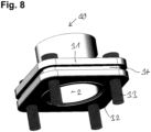
- FIG. 8 An embodiment of the second aspect not embodying the first aspect is shown in Fig. 8 .
- the component 30 of the third embodiment of the present invention shown in Fig. 8 equally is a fluid guiding component having a fluid duct to be connected by the flange connection element 31 to a flange connection counterpart.
- the flange connection element 31 is a plate-like-element having holes for the screws and/or bolts 33, wherein the contact surface extends essentially over the entire lower surface 32 of the plate-like-flange connection element 31.
- the plate-like-element 31 therefore forms a supporting part for the screws and/or bolts that does not have a clearance with respect to the flange connection counterpart, but is pressed by the screws and/or bolts onto the contact surface of the flange connection counterpart.
- the plate-like-element has a groove 34 extending along a side-surface for reducing edge loads.
- the groove 34 extends around the entire circumference of the plate-like-flange connection element 31. Further, the flange connection element is essentially square shaped.
- the groove 34 may only extend over parts of the circumference.
- the groove 34 may only extend around the corners and/or the areas surrounding the screws and/or bolts 33, but may not be present in at least one middle section of the flange connection element.
- the components of the present invention are preferably made from metal, in particular from iron and preferably from steel.
- the components may be casted and/or forged and/or machined parts.
- Both the supporting parts of the first aspect, and/or the groove of the second aspect can be molded in the raw part, without additionally machining to reduce machining cost.
- the variable thickness in the flange height provided by a recess and/or groove may be produced by machining of the raw part.
- at least the contact surface and/or step portions for the screw heads and/or nuts may be machined in order to improve precision.
- the present invention is most preferably applied for providing a flange connection between different components of an internal combustion engine.
- the inventive flange connection may be used to connect an air inlet manifold and/or an exhaust gas manifold to a cylinder head of the engine.
- the component 18 is an exhaust gas duct 19, provided with two flange connection elements 1 corresponding to the components shown in Fig. 1 to 4 , for connecting the exhaust gas duct 19 to cylinder heads 20.
- screws 5 are used for connecting the flange connection elements of components 1 to the cylinder heads 20.
- Using the present invention allows to use a geometry of the exhaust gas connection between the cylinder heads and the exhaust gas duct 19 that has a rectangle shape with a longer and shorter side, and therefore uses the available space in a better way, while at the same time providing a particular good leakage tightness.
- the present invention requires no additional machining and even less components by removing the sleeves.
- the improvement is achieved by a particular shape of the flange connection element without adding components or having to redesign the interface between the component and the other component.
- the present invention can be applied to all axial bolted or screwed flange assemblies where axial sealing is needed.
- the present invention is of particular advantage where there is a long distance between the bolts and/or screws or low contact pressure.
- the present invention allows a better repartition of the contact pressure, and/or reduces edge loads. Thereby, improved sealing is achieved.
Landscapes
- Engineering & Computer Science (AREA)
- General Engineering & Computer Science (AREA)
- Mechanical Engineering (AREA)
- Chemical & Material Sciences (AREA)
- Combustion & Propulsion (AREA)
- Connection Of Plates (AREA)
Description
- The present invention relates to a component having a flange connection element connectable to a flange connection counterpart of another component by bolts and/or screws, the flange connection element comprising a contact surface to be pressed against a contact surface of the flange connection counterpart. According to the invention, the component is part of an internal combustion engine. Preferably, the component may be a fluid guiding component comprising a fluid duct connectable to a fluid duct of the other component by the flange connection element.
- When a flange connection element is used to connect fluid guiding ducts with each other, it is important to avoid leakages at the interface between the two components. For this purpose, it is important that the pressure is equally distributed over the contact surface of the flange connection.
- However, in usual flange connections, where the contact surface has holes through which the screws or bolts are guided for pressing the contact surface against the flange connection counterpart, it is sometimes difficult to obtain sufficient leakage tightness. In particular, if the distance between the bolts or screws is too high, for example because of a rectangular shaped interface, the contact pressure may be located around the screw holes with a very high value, whereas the center of the flange has little contact pressure. Further, due to the high contact pressure on the edges, the flange is prevented from performing the necessary relative movement under thermal expansion of the flange, such that the contact pressure in the center of the flange is additionally lowered.
- Conventional ways of avoiding this problem have been to increase the number of screws, which however leads to additional costs and additional mounting space.
- Alternatively, the geometry of the interface could be changed to reduce the distance between the screws. In particular, a square shaped flange with four screws is recommended for large dimensions. Further, a round flange with three screws at 120° is recommended for small dimensions. However, such a change of the geometry requires a redesign and therefore involves additional costs.
- Further, increasing the height of the screws may have positive effect on the problem, but equal involves higher costs. Increasing the number of layers on the gasket could equally help, but not in all cases.
- One further option would be a heat treatment of the component, which can help to release internal strains in the material and bring more dimensional stability to the component, especially through thermal cycles. Again, this involves additional costs.
-
Document DE 10 2008 010629 A1 shows a two-part construction with a separate flange connection element comprising the screw holes, the flange connection element abutting against abutment portions of a flange portion of a duct. - Documents
DE 199 54 317 A1 ,EP 1 270 890 A2EP 2 253 874 A1US 2013/140807 A1 show flange connection elements having a conical or spherical contact surface. - The present invention is directed to providing a component having a flange connection element providing improved leakage tightness while avoiding the problems associated to the above discussed known measures.
- This object is solved in a first aspect by a component according to
claim 1 and in a second aspect by component according to claim 6. Preferred embodiments of the present invention are the subject matter of the dependent claims. - The present invention provides, in a first aspect, a component having a flange connection element connectable to flange connection counterpart of another component by bolts and/or screws, wherein the component is part of an internal combustion engine. The flange connection element comprises a contact surface to be pressed against a contact surface of the flange connection counterpart. The contact surface extends in a single plane and the component is formed integrally from a single or multiple materials, The present invention is characterized in that the contact surface of the flange connection element is formed such that it does not completely surround at least one of the bolts and/or screws.
- The inventors of the present invention have realized that thereby, the contact pressure in the contact surface next to the screws and/or bolts can be reduced, and the contact pressure in the remaining parts of the contact surface can be increased.
- According to the first aspect, the flange connection element is connectable to the flange connection counterpart by four bolts and/or screws arranged in the corners of a rectangle, wherein a first side of the rectangle is longer than a second side of the rectangle, wherein the two opposing first sides of the rectangle intersect with the contact surface and the two opposing second sides of the rectangle do not intersect with the contact surface.
- Preferably, the contact surface of the flange connection element does not surround the at least one bolt and/or screw at all. In particular, this means that there is no line drawn between two points of the contact surface that would cross the bolt and/or screw. Further, preferably, the contact surface extends at a certain distance to the at least one bolt or screw.
- In a preferred embodiment of the present invention, the flange connection element has at least one supporting part for the at least one bolt and/or screw arranged in such a way that there is a clearance between the supporting part and the flange connection counterpart and/or the level of the contact surface of the connection element in the direction perpendicular to the contact surface. This means the supporting part supporting the bolt and/or screw is not in contact with the flange connection counterpart when the flange connection element is mounted to the contact surface of the flange connection counterpart. Therefore, there is no contact pressure between the supporting part and the flange connection counterpart.
- Therefore, preferably, the contact surface of the flange connection element does not extend into the area of the supporting part. This can be provided by removing, from a standard flange connection design, the material of the contact surface around the screws and/or bolts.
- Preferably, the supporting part has a hole for mounting the screw and/or bolt. For example, the supporting part may have a hole and a step portion on which a screw head or a nut can be supported.
- In a preferred embodiment of the present invention, the supporting part projects from a sidewall of the component to extend outside of the area of the contact surface, such that a tensioning of the screw and/or bolt creates a bending force in an area of the component where the supporting part is connected to the sidewall. Such a construction will distribute the contact pressure more evenly within the contact surface.
- Preferably, the supporting part has a clearance with respect to the level of the contact surface that decreases towards the middle of the flange connection element. Alternatively or in combination, the supporting part may have a width in a direction perpendicular to the contact surface that increases towards the middle of the flange connection element. Both measures, especially when combined, will concentrate more force in a middle part of the flange connection element, and therefore provide more contact pressure in this area.
- The component may in particular have two supporting parts arranged on the opposite sides of the flange connection element, which together form a yoke for transmitting contact pressure to a middle part of the flange connection element.
- The two supporting parts arranged on the opposite sides of the flange connection element may together have a general V-shape. Such a V-shape will distribute the pressure such that there is sufficient contact pressure in the middle part of the flange connection element, because the tip of the V-shape is arranged in this area.
- In a preferred embodiment of the present invention, the contact surface of the flange connection element is surrounded by at least two and preferably by at least three or four bolts and/or screws. Preferably, what has been described above with respect to at least one bolt and/or screw also applies to the at least two and preferably at least three or four bolts of the flange connection. Further preferably, it applies to all the bolts and/or screws of the flange connection.
- Further, the component preferably has at least two and preferably at least three or four supporting parts surrounding the contact surface of the flange connection element. Again, what has been described above with respect to the at least one supporting part preferably applies to the at least two and preferably at least three or four supporting parts and more preferably to all supporting parts.
- The present invention provides, in a second aspect, a component having a flange connection element connectable to a flange connection counterpart of another component by bolts and/or screws, wherein the component is part of an internal combustion engine. The flange connection element comprises a contact surface to be pressed against a contact surface of the flange connection counterpart. The second aspect is characterized in that the flange connection element has a recess in at least one of its side surfaces reducing the contact pressure in an edge part of the contact surface extending below the recess.
- In particular, the inventors of the present invention have realized that by providing a recess in a side surface of the flange connection element, the edge load can be reduced in the contact surface extending below the recess. Thereby, the component is allowed to move relative to the flange connection counterpart under thermal extension more easily. The reduction of the contact pressure in the edge part is provided because the material of the flange connection element between the edge part of the contact surface and the recess is allowed to bend more easily than if no recess was provided.
- The second aspect can be used both with a conventional flange design, as well as with an inventive flange design according to the first aspect described above.
- In a component according to the second aspect, the flange connection element has at least one supporting part for at least one bolt and/or screw. The supporting part may be a conventional flange connection supporting part, or a supporting part as described above with respect to the first aspect of the present invention.
- In any case, the supporting part preferably has a hole for mounting the screw and/or bolt.
- In a first variant of the second aspect, the recess is arranged in the side surface of the supporting part. This variant is preferably used when the supporting part has a conventional design, e.g. is formed as a plate.
- In particular, the first variant may be used when the contact surface of the flange connection element extends beneath the supporting part, and preferably covers the entire lower surface of the supporting part.
- Alternatively, or in addition, the first variant may be used when the contact surface surrounds the screw and/or bolt at least in part and/or preferably surrounds the screw and/or bolt completely. For example, in such construction, the supporting part may be a plate-like-element having a hole for the screw and/or bolt, wherein the contact surface extends over the entire lower surface of the plate-like-element. In this case, the recess preferably extends along the side surfaces of the plate-like-element.
- In the second variant, the recess is arranged in an area of the flange connection element arranged between the supporting part and the contact surface. This second variant is preferably used in combination with a design of the supporting part according to the first aspect of a present invention discussed above, i.e. having a supporting part projecting from a sidewall of the component and/or having a clearance with respect to the flange connection counterpart and/or the level of the contact surface.
- In such a construction, the recess preferably extends at least in an area below the supporting part or in a sidewall of the flange connection element from which the supporting part projects in an area above the recess.
- In a preferred embodiment, which may be combined with the first and/or the second variant described above, the recess is formed by groove extending along a side surface of the flange connection element. In particular, the groove may extend with a distance to the contact surface in the side surface of the flange connection element. The distance between the groove and the contact surface defines the thickness of the material arranged above the edges of the contact surface, and therefore the bending properties of this part of the flange connection element.
- Preferably, the distance between the recess and the contact surface is generally constant at least over part of the groove, and more preferably over the main part of the extension of the groove. Thereby, the edge load is evenly reduced along the extension of the groove.
- In the following, preferred embodiments of the present invention, which can be applied both to the first aspect, the second aspect, and a combination of the first and second aspect, are described.
- In an embodiment of the present invention, the flange connection element and/or the contact surface has an extension in a first direction that is larger than the extension in a second, perpendicular direction. In such a construction, the advantages provided by the present invention are particularly important, because the longer extension in a first direction will make it more difficult to provide sufficient contact pressure in a middle section of the first direction with conventional means, and therefore the advantages provided by the present invention are more important.
- Preferably, when combined with the second aspect of the present invention, the recess and in particular the groove forming the recess extends along at least one and preferably along at least two opposing side surfaces extending in the second, shorter direction. This is because along the shorter direction, there is more edge load, which is then reduced by the recess.
- Alternatively or in addition, the recess of the second aspect is not provided at least in the middle section of at least one and preferably of two opposing side surfaces extending the first, longer direction. This is because in this area, the contact pressure is not as high, anyway.
- Preferably, the groove extends over the entirety of the two opposing short side surfaces, and into the two opposing longer side surfaces, but does not reach into a middie section of the longer side surfaces.
- In an alternative embodiment, however, the groove of the second aspect of the present invention may also extend around the entire circumference of the flange connection element.
- Further, the flange connection element and/or the contact surface may have a general form of a rectangle with different side lengths, and/or the general form of an oval. The rectangle may have sharp or rounded edges.
- According to the first aspect and in a preferred embodiment of the second aspect, the flange connection element is connectable to the flange connection counterpart by four bolts and/or screws arranged in the corners of a rectangle. This means that the center points of the bolts and/or screws form a rectangle. More preferably, the center lines of the screws and/or bolts form the four side edges of a virtual cuboid.
- A first side of the rectangle formed by the bolts and/or screws is longer than a second side of the rectangle.
- According to the first aspect and in a preferred embodiment of the second aspect, two opposing first sides of the rectangle intersect with the contact surface. This means that if a line is drawn between the central points of two bolts and/or screws on at least one and preferably on two opposing first sides, this line will extend above the contact surface. This is of particular advantage if this first side or these two opposing first sides are the longer sides because this will allow to provide more contact pressure in the middle section of the flange connection element along these first sides.
- According to the first aspect and in a preferred embodiment of the second aspect, two opposing second sides of the rectangle does or do not intersect with the contact surface. This means that a line drawn between center points of two adjacent bolts and/or screws along a second side and preferably along two opposing second sides will not extend above the contact surface, but next to the contact surface. In particular, the contact surface may be arranged between these opposing second sides of the rectangle. Preferably, the second sides are the shorter sides. Thereby, pressure is reduced along these sides.
- In particular, the supporting parts may project from the shorter, second sides in a direction of the first, longer sides.
- Further preferably, the recess and/or groove of the second aspect is provided on the second, shorter sides, preferably below the supporting parts.
- The contact surface may extend substantially along the first side and/or the first sides. Alternatively or in combination, the contact surface may extend within a distance to the second side or second sides.
- In a preferred embodiment of the present invention, the contact surface essentially extends in a single plane. This plane forms a pressing plane when pressing the contact surface to the contact surface of the flange connection counterpart.
- In a further preferred embodiment of the present invention, a sealing element is provided between the contact surface of the component and the flange connection counterpart. Preferably, the sealing element extends from the contact surface to at least one and preferably at least two screws and/or bolts. In particular, if the first aspect of the present invention is applied, it may be difficult to exactly position the sealing element if it is only arranged in the area of the contact surface. Therefore, by having the sealing element extend to at least one and preferably at least two screws and/or bolts, the screws and/or bolts can be used for positioning the sealing element. Preferably, the sealing element surrounds at least one and preferably at least two screws and/or bolts. This will make the positioning particularly easy. Preferably, the sealing element is provided with holes for the at least one and preferably at least two screws and/or bolts.
- The contact surface may be provided with a structure for improving the sealing qualities.
- The component of the present invention is preferably a fluid guiding component. In particular, the component may comprise a fluid duct connectable to a fluid duct of the other component by the flange connection element. Preferably, the contact surface surrounds the fluid duct. The fluid duct may extend through the flange connection element in a direction perpendicular to the contact surface.
- Alternatively or in combination, the contact surface may be provided with a seal.
- The inventive component may, in a preferred embodiment, comprise at least two flange connection elements described above. The flange connection elements may have contact surfaces extending parallel to each other. Further, the contact surfaces of the two flange connection elements may extend in the same plane.
- Alternatively or in combination with this, flange connection elements may be arranged on a fluid guiding element of the component that extends in a direction that is essentially parallel to a plane of at least one contact surface and preferably essentially parallel to the planes of the at least two contact surfaces.
- In a preferred embodiment of the present invention, the component may be a component of an air inlet system and/or of an exhaust system of the internal combustion engine. In particular, the component may be an air intake manifold and/or an exhaust gas manifold connectable to a cylinder head of the internal combustion engine.
- The present invention further comprises an internal combustion engine comprising at least one component as described above. More preferably, the internal combustion engine comprises several components as described above.
- The component on the present invention is preferably formed from metal. Preferably, the component is formed from iron, more preferably from steel.
- The component may be formed by casting and/or machining.
- The present invention will now be described using drawings and embodiments.
- The drawings show in
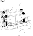
- Fig. 1:
- A perspective view of a first embodiment of a flange connection element using screws and/or bolts;
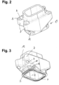
- Fig. 2:
- the first embodiment in a perspective view from above;
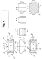
- Fig. 3:
- the first embodiment in a perspective view from below;
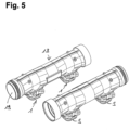
- Fig. 4:
- a bottom, two side views, a top view and three cuts through the first embodiment;
- Fig. 5:
- a second embodiment of an inventive component comprising a fluid duct comprising two flange connection elements as described with respect to the first embodiment;
- Fig. 6:
- a cut through the second embodiment connected to another component;
- Fig. 7:
- a side view of the second embodiment attached to another component and
- Fig. 8:
- a third embodiment of the present invention where only the second aspect of the present invention is implemented.
- A first embodiment of an inventive component will now be described with respect to
Fig. 1 to 4 . The first embodiment combines the first and the second aspect of the present invention. However, the two aspects of the present invention as shown in the first embodied could also be provided on their own and independently from each other. - In the embodiment, the
component 1 is a fluid guiding component, having afluid duct 2 connectable to a fluid duct of anothercomponent 20 via a flange connection element. In fact, in the embodiment shown inFig. 1 to 4 , the component is essentially formed only by the flange connection element. The component may have other parts not shown inFig. 1 to 4 , extending form the open side of theduct 2. Alternatively, the component may only have the elements shown inFig. 1 to 4 . - The flange connection element of the
component 1 is connectable to a flange connection counterpart of the anothercomponent 20 byscrews 5. For this purpose, the flange connection element hasholes 8 through which thescrews 5 extend, and a step 9 on which the screw heads may rest to exert pressure on the flange connection element. Instead of screws, bolts could be used. - The flange connection element has a
contact surface 3, shown inFig. 3 , with which it is pressed against a contact surface of the flange connection counterpart of theother element 20.Sealing structures 4 may extend along thecontact surface 3. The contact surface extends along a plane perpendicular to the direction of thescrews 5. - As can be seen from
Fig. 3 , the contact surface extends around theduct 2 for sealingly connecting theduct 2 of thecomponent 1 to a duct of theother component 20. As can be seen inFig. 1 , a sealingelement 11 may be provided between thecontact surface 3 of thecomponent 1 and the contact surface of the flange connection counterpart of theother component 20. - According to a first aspect of the present invention, the
contact surface 3 is reduced, as compared to a conventional construction, by removing all the material of the contact surface around the screw holes 8 of the flange connection element. - Therefore, according to the first aspect, the
contact surface 3 does not surround thescrews 5. In particular, all four screws used in the embodiment shown inFig. 1 to 4 are arranged outside of the contact surface. - Further, the flange connection element has supporting parts 7 for supporting the
screws 5, provided with theholes 8. Because the material of the contact surface is removed around the screws, the supporting parts 7 have aclearance 10 with respect to the flange connection counterpart of theother component 20. In particular, the supporting parts 7 project from asidewall 21 of the flange connection element. - The
clearance 10 of the supporting parts 7 decreases from two opposing sides of the flange connection element towards a middle section. This means that the distance D between alower surface 11 of the supporting parts and the level of the contact surface decreases from two opposing sides towards a middle section of a flange connecting element. At the same time, the width W of the supporting part increases towards the middle section. The two supporting parts thereby form together a general V-shape. - This is of particular advantage because in the embodiment shown in
Fig. 1 to 4 , the flange connection element has a first, longer side, and a second shorter side. The decrease of the clearance and the increase of the width are along the first, longer side. Thereby, more contact pressure is provided to the middle section 22 of the flange connection element which otherwise would receive lower contact pressures. - In the embodiment shown in
Fig. 1 to 4 , the center points of thescrews 5 and the screw holes 8 form avirtual rectangle 16 shown in the view from above and in the view from below inFig. 4 . This rectangle has two longerfirst sides 16 and 16' and two shortersecond sides 17 and 17'. - As can be seen from the view from the top in the top left corner of
Fig. 4 , the secondshorter sides 17 and 17' of the rectangle do not intersect with thecontact surface 13. In fact, thecontact surface 13 does not extend at all in the area between the screws or screw holes on the second, shorter side of the flange connection element. - In contrast, the longer sides 16 and 16' of the
rectangle 15 intersect with thecontact surface 13, which extends between the screws or screw holes along the longer sides of the flange connection element. - By this construction, the contact pressure in the middle section of the longer sides is increased, and the contact pressure along the shorter sides is decreased.
- As can be seen from
Fig. 4 , the contact surface essentially forms a rectangle with rounded corners, havinglonger sides 13 and 13' andshorter sides 14 and 14'. - The longer sides 13 and 13' extend essentially along the longer sides 16 and 16' of the
rectangle 15, while theshorter sides 14 and 14' extend with a certain distance, which is larger than the radius of the screw holes 8, next to thesides 17 and 17' of therectangle 15. - However, the present invention is not restricted to a rectangle form of the contact surface, and may equally be applied for example to an oval or elliptic form having a longer and a shorter side.
- If the flange connection element has a longer and shorter side, the supporting parts 7 preferably project from the sidewalls of the shorter sides in the direction of the longer sides.
- In the embodiment shown in
Fig. 1 and4 , the supporting parts 7 are arranged in the four corners of the flange connection element. Along the longer sides, the supporting elements 7 are joined by a sidewall of the flange connection element, the sidewall extending substantially in a plane perpendicularly to thecontact surface 3 and preferably having a V-shape. - The two opposing supporting parts together with the sidewall therefore form a yoke directing the force applied by the screws into the middle section 22 of the flange connection element.
- Along the shorter sides, the supporting parts 7 separately project from the sidewall in the embodiment shown in
Fig. 1 to 4 . However, in an alternative embodiment, they may equally be joined by a sidewall. However, also in this case, the sidewall joining the supporting parts 7 along the shorter side preferably has a clearance with respect to the flange connection counterparts and/or a distance D with respect to the plane of thecontact surface 3. - As can be seen in
Fig. 1 , in the first embodiment, there is a sealingelement 11 extending beyond thecontact surface 3 to thescrews 5, and having holes through which thescrews 5 extend. Thereby, thescrews 5 can be used for correctly placing of the sealingelement 11 with respect to theduct 2 of thecomponent 1. - In a second aspect of the present invention, equally embodied in the embodiment shown in
Fig. 1 to 4 , there is agroove 12 extending in the flange height. This feature brings more flexibility on the edges of the contact surface and therefore allows a sliding movement of the component with respect to the other component under temperature changes because of thermal expansion. - In the embodiment shown in
Fig. 1 and4 , where the second aspect is combined with the first aspect, thegroove 12 extends below the projecting supporting parts 7 along the shorter sides, and slightly around the corners into the longer sides under the supporting parts. However, it does not extend into the middle section, where the pressure should not be reduced. - In the embodiments shown, the
groove 12 reduces the thickness of the sidewalls of the fluid duct, which preferably has flat inner sidewalls also in the area of thegroove 12 in order to avoid fluid disturbances. The groove leaves some material above the contact surface, which however bends more easily, therefore reducing the edge loads. - The second aspect of the present invention is, even though it is combined in the first embodiment with the first aspect, independent of the first aspect, and can also be used in any kind of flange connection element.
- In particular, the groove can be implemented on all axial bolted or screwed flanges, where high pressure contact is located around the screws or bolts, in order to release the contact pressure somewhat on the outer edges of the flange where no sealing is needed.
- An embodiment of the second aspect not embodying the first aspect is shown in
Fig. 8 . The component 30 of the third embodiment of the present invention shown inFig. 8 equally is a fluid guiding component having a fluid duct to be connected by theflange connection element 31 to a flange connection counterpart. In the embodiment shown inFig. 8 , theflange connection element 31 is a plate-like-element having holes for the screws and/orbolts 33, wherein the contact surface extends essentially over the entirelower surface 32 of the plate-like-flange connection element 31. - The plate-like-
element 31 therefore forms a supporting part for the screws and/or bolts that does not have a clearance with respect to the flange connection counterpart, but is pressed by the screws and/or bolts onto the contact surface of the flange connection counterpart. - As shown in
Fig. 8 , the plate-like-element has agroove 34 extending along a side-surface for reducing edge loads. - In the embodiment shown in
Fig. 8 , thegroove 34 extends around the entire circumference of the plate-like-flange connection element 31. Further, the flange connection element is essentially square shaped. - However, also in case of conventional flange connection element, the
groove 34 may only extend over parts of the circumference. In particular, thegroove 34 may only extend around the corners and/or the areas surrounding the screws and/orbolts 33, but may not be present in at least one middle section of the flange connection element. - The components of the present invention are preferably made from metal, in particular from iron and preferably from steel. The components may be casted and/or forged and/or machined parts.
- Both the supporting parts of the first aspect, and/or the groove of the second aspect, can be molded in the raw part, without additionally machining to reduce machining cost. Alternatively, the variable thickness in the flange height provided by a recess and/or groove may be produced by machining of the raw part. Preferably, at least the contact surface and/or step portions for the screw heads and/or nuts may be machined in order to improve precision.
- The present invention is most preferably applied for providing a flange connection between different components of an internal combustion engine. In particular, the inventive flange connection may be used to connect an air inlet manifold and/or an exhaust gas manifold to a cylinder head of the engine.
- This is shown in the second embodiment with respect to
Fig. 5 to 7 . In these embodiments, thecomponent 18 is anexhaust gas duct 19, provided with twoflange connection elements 1 corresponding to the components shown inFig. 1 to 4 , for connecting theexhaust gas duct 19 tocylinder heads 20. - As can be seen in
Fig. 5 to 7 , screws 5 are used for connecting the flange connection elements ofcomponents 1 to the cylinder heads 20. - Using the present invention allows to use a geometry of the exhaust gas connection between the cylinder heads and the
exhaust gas duct 19 that has a rectangle shape with a longer and shorter side, and therefore uses the available space in a better way, while at the same time providing a particular good leakage tightness. - Compared to state of the art flange designs, the present invention requires no additional machining and even less components by removing the sleeves. The improvement is achieved by a particular shape of the flange connection element without adding components or having to redesign the interface between the component and the other component.
- The present invention can be applied to all axial bolted or screwed flange assemblies where axial sealing is needed. Typically, the present invention is of particular advantage where there is a long distance between the bolts and/or screws or low contact pressure.
- The two aspects of the present invention can be combined, but can also be applied independently of each other. The particular dimensions of the various components and design features will usually be fine-tuned and adjusted by simulation to the specific design of the interface.
- The present invention allows a better repartition of the contact pressure, and/or reduces edge loads. Thereby, improved sealing is achieved.
Claims (15)
- A component (1) having a flange connection element connectable to a flange connection counterpart of another component (20) by bolts and/or screws (5), wherein the component is part of an internal combustion engine, the flange connection element comprising a contact surface (3) to be pressed against a contact surface of the flange connection counterpart (20), wherein the contact surface (3) extends in a single plane and the component is formed integrally from a single or multiple materials, characterized in that the flange connection element is connectable to the flange connection counterpart by four bolts and/or screws (5) arranged in the corners of a rectangle (16), wherein a first side of the rectangle is longer than a second side of the rectangle (16), the contact surface (3) of the flange connection element is formed such that it does not completely surround at least one of the bolts and/or screws (5), wherein the two opposing first sides of the rectangle (16) intersect with the contact surface (3) and the two opposing second sides of the rectangle (16) do not intersect with the contact surface (3).
- The component of claim 1, wherein the flange connection element has at least one supporting part (7) for the at least one bolt and/or screw (5) arranged in such a way that there is a clearance (10) between the supporting part (7) and the flange connection counterpart (20) and/or the level of the contact surface (3) in a direction perpendicular to the contact surface (3), wherein the supporting part (7) preferably has a hole (8) for mounting the screw and/or bolt (5).
- The component of claim 2, wherein the supporting part (7) projects from a side wall (21) of the component to extend outside of the area of the contact surface (3).
- The component of claim 2 or 3, wherein the supporting part (7) has a clearance (10) with respect to the level of the contact surface (3) that decreases towards the middle of the flange connection element and/or wherein the supporting part (7) has a width (W) in a direction perpendicular to the contact surface (3) that increases towards the middle of the flange connection element, and/or wherein the component has two supporting parts (7) arranged on the opposite sides of the flange connection element, which together form a yoke for transmitting contact pressure to a middle part of the flange connection element, wherein preferably the component has two supporting parts (7) arranged on opposite sides of the flange connection element which together have a general V-shape.
- The component of any one of the previous claims, wherein the contact surface (3) of the flange connection element is surrounded by at least two and preferably by at least three or four bolts and/or screws (5) and/or wherein the component has at least two and preferably at least three or four supporting parts (7) surrounding the contact surface (3) of the flange connection element.
- A component (1) having a flange connection element connectable to a flange connection counterpart of another component (20) by bolts and/or screws (5), wherein the component is part of an internal combustion engine, the flange connection element comprising a contact surface (3) to be pressed against a contact surface of the flange connection counterpart, the flange connection element having at least one supporting part (7, 31) for at least one bolt and/or screw (5), in particular a component according to any one of the preceding claims,
characterized in that
the flange connection element has a recess (12, 34) in at least one of its side surfaces reducing the contact pressure in an edge part of the contact surface (3) extending below the recess, wherein the recess (12, 34) is arranged in a side surface of the supporting part (31) or an area of the flange connection element arranged between the supporting part (7) and the contact surface (3). - The component of claim 6, wherein the supporting part (7, 31) has a hole (8) for mounting the screw and/or bolt (5), and/or wherein the contact surface (3) of the flange connection element extends beneath the supporting part (31) and/or surrounds the screw and/or bolt (3) at least in part and more preferably completely.
- The component of claim 6 or 7, wherein the recess (12, 34) is formed by a groove extending along the side surface of the flange connection element, the groove (12, 34) preferably extending with a distance to the contact surface (3), the distance to the contact surface (3) preferably being constant at least over a part and further preferably over the main part of the extension of the groove (12, 34).
- The component of any one of the preceding claims, wherein the flange connection element and/or the contact surface (3) has an extension in a first direction that is larger than the extension in a second, perpendicular direction, wherein the groove (12, 34) preferably extends along at least one and preferably two opposing side surfaces extending in the second direction, and/or preferably the recess (12, 34) is not provided at least in a middle section of at least one and preferably two opposing side surfaces extending in the first direction and/or wherein the flange connection element and/or the contact surface (3) has the general form of a rectangle with different side lengths and/or of an oval.
- The component of any one of the preceding claims, wherein the contact surface (3) extends substantially along the first side/s and/or the contact surface extends with a distance to the second side/s.
- The component of any one of the preceding claims, where a sealing element (11) is provided between the contact surface (3) of the component and the flange connection counterpart, wherein the sealing element (11) preferably extends from the contact surface (3) to at least one and preferably at least two screws and/or bolts (5) and preferably surrounds at least one and preferably at least two screws and/or bolts (5).
- The component of any one of the preceding claims, wherein the component is a fluid guiding component and preferably comprises a fluid duct (2) connectable to a fluid duct of the other component (20) by the flange connection element, the contact surface (3) preferably surrounding the fluid duct (2), and/or wherein the contact surface (3) is provided with a seal.
- The component of any one of the preceding claims, comprising at least two flange connection elements as described in any one of the preceding claims, the flange connection elements preferably having contact surfaces (3) extending parallel to each other and/or the flange connection elements being arranged on a fluid guiding element (19) extending in a direction that is parallel to a plane of at least one contact surface (3).
- The component of any one of the preceding claims, wherein the component is a component of an air inlet system and/or of an exhaust system of the internal combustion engine, wherein the component preferably is an air intake manifold and/or and exhaust gas manifold (19) connectable to a cylinder head (20) of the internal combustion engine.
- An internal combustion engine comprising at least one component (1) according to any one of the preceding claims.
Applications Claiming Priority (2)
| Application Number | Priority Date | Filing Date | Title |
|---|---|---|---|
| DE102017111472 | 2017-05-24 | ||
| PCT/EP2018/054938 WO2018215100A1 (en) | 2017-05-24 | 2018-02-28 | A component having a flange connection element |
Publications (2)
| Publication Number | Publication Date |
|---|---|
| EP3612724A1 EP3612724A1 (en) | 2020-02-26 |
| EP3612724B1 true EP3612724B1 (en) | 2024-10-23 |
Family
ID=61691437
Family Applications (1)
| Application Number | Title | Priority Date | Filing Date |
|---|---|---|---|
| EP18711834.4A Active EP3612724B1 (en) | 2017-05-24 | 2018-02-28 | A component having a flange connection element |
Country Status (3)
| Country | Link |
|---|---|
| US (1) | US11215104B2 (en) |
| EP (1) | EP3612724B1 (en) |
| WO (1) | WO2018215100A1 (en) |
Families Citing this family (2)
| Publication number | Priority date | Publication date | Assignee | Title |
|---|---|---|---|---|
| USD907065S1 (en) * | 2019-08-09 | 2021-01-05 | Wehrli Custom Fabrication, Inc. | Adapter for installation of a turbocharger |
| USD1014558S1 (en) * | 2019-11-19 | 2024-02-13 | Transportation Ip Holdings, Llc | Support bracket |
Family Cites Families (15)
| Publication number | Priority date | Publication date | Assignee | Title |
|---|---|---|---|---|
| US1376620A (en) | 1919-12-04 | 1921-05-03 | Hildebrand Reinhard | Cylinder-head for internal-combustion engines |
| US3188116A (en) | 1962-08-03 | 1965-06-08 | Chemical Construction Corp | Piping joint |
| JPS5867944U (en) | 1981-10-30 | 1983-05-09 | ヤンマーディーゼル株式会社 | cylinder head |
| US4649614A (en) * | 1984-03-09 | 1987-03-17 | In-Mech Industries | Method and apparatus for repair of flanged exhaust connections |
| US4647353A (en) | 1986-01-10 | 1987-03-03 | Mccready David | Cathodic protection system |
| DE19954317A1 (en) | 1999-11-11 | 2001-05-17 | Hans A Haerle | Connector for joining exhaust gas manifold pipe with air gap insulation to catalytic converter comprises two flanges, converter pipe fitting into one of flanges and bore in other being stepped to accommodate manifold pipe |
| JP3515767B2 (en) | 2001-06-13 | 2004-04-05 | 本田技研工業株式会社 | Vibration absorber in engine exhaust system |
| US20040177609A1 (en) * | 2001-12-07 | 2004-09-16 | Moore Dan T. | Insulated exhaust manifold having ceramic inner layer that is highly resistant to thermal cycling |
| FR2883063B1 (en) * | 2005-03-08 | 2007-04-20 | Renault Sas | DEVICE FOR CONNECTING A TUBE AND AN EXHAUST LINE ELEMENT |
| DE102005026559A1 (en) | 2005-06-08 | 2006-12-14 | Srd Maschinenbau Gmbh | Installation assembly for radio frequency identification transponder has plastic foam separation layer |
| DE102008010629A1 (en) | 2008-02-22 | 2009-09-03 | Daimler Ag | Flange for piping of exhaust system of motor vehicle i.e. truck, has attachment openings provided for corresponding pins to attach flange with another flange, and recesses extending between assigned opening and outer side of flange |
| DE102009022217A1 (en) * | 2009-05-20 | 2010-11-25 | Audi Ag | flange |
| US20130140807A1 (en) | 2011-12-06 | 2013-06-06 | Gerald Milroy Van Dusen | Clamp with spring loaded bolt to repair broken exhaust manifold flange bolts |
| EP2746559B1 (en) | 2012-12-21 | 2016-06-29 | Caterpillar Motoren GmbH & Co. KG | Cylinder head and engine block configuration |
| CN111936734B (en) | 2017-05-15 | 2022-12-20 | 康明斯公司 | Cylinder head bolt boss cutout |
-
2018
- 2018-02-28 EP EP18711834.4A patent/EP3612724B1/en active Active
- 2018-02-28 US US16/616,451 patent/US11215104B2/en active Active
- 2018-02-28 WO PCT/EP2018/054938 patent/WO2018215100A1/en not_active Ceased
Also Published As
| Publication number | Publication date |
|---|---|
| US20200173405A1 (en) | 2020-06-04 |
| EP3612724A1 (en) | 2020-02-26 |
| US11215104B2 (en) | 2022-01-04 |
| WO2018215100A1 (en) | 2018-11-29 |
Similar Documents
| Publication | Publication Date | Title |
|---|---|---|
| TWI516740B (en) | Plate heat exchanger with mounting flange | |
| JP6501540B2 (en) | Metal gasket | |
| EP3612724B1 (en) | A component having a flange connection element | |
| CN101469630A (en) | Exhaust manifold | |
| US20140116372A1 (en) | Gasket, throttle body | |
| US20090311551A1 (en) | Connecting Structure of Metal Plates | |
| US10113505B2 (en) | Gasket and engine with the gasket | |
| US8839758B2 (en) | Internal combustion engine comprising a connecting assembly for a cylinder head | |
| US11098636B2 (en) | Exhaust manifold to turbine connection | |
| EP3105475B1 (en) | Cylinder head gasket with compression control features | |
| KR100696568B1 (en) | Metal gasket | |
| US6428016B1 (en) | Metal cylinder head gasket with compressibility adjusting slits | |
| KR100739500B1 (en) | Cylinder head gasket | |
| EP3280882B1 (en) | Exhaust gas supply arrangement of an exhaust gas turbocharger | |
| US9422854B2 (en) | Exhaust gas evacuation system structure for internal combustion engine | |
| EP3564559B1 (en) | Metal gasket | |
| CN107725161B (en) | Exhaust manifold for four-cylinder turbine engine | |
| US6343574B1 (en) | Load distribution rib for the combustion deck of an internal combustion engine | |
| JP2005164039A (en) | Gasket including steel plate provided with thick portion | |
| CN114829745B (en) | Exhaust manifold to turbine connection | |
| JP3604976B2 (en) | Intake and exhaust system metal gasket | |
| JP6983112B2 (en) | Exhaust system parts fastening structure | |
| CN107429598A (en) | Devices for attaching exhaust collectors | |
| EP1143122B1 (en) | Exhaust manifold for an internal combustion engine | |
| EP3163060B1 (en) | Cylinder block and engine body |
Legal Events
| Date | Code | Title | Description |
|---|---|---|---|
| STAA | Information on the status of an ep patent application or granted ep patent |
Free format text: STATUS: UNKNOWN |
|
| STAA | Information on the status of an ep patent application or granted ep patent |
Free format text: STATUS: THE INTERNATIONAL PUBLICATION HAS BEEN MADE |
|
| PUAI | Public reference made under article 153(3) epc to a published international application that has entered the european phase |
Free format text: ORIGINAL CODE: 0009012 |
|
| STAA | Information on the status of an ep patent application or granted ep patent |
Free format text: STATUS: REQUEST FOR EXAMINATION WAS MADE |
|
| 17P | Request for examination filed |
Effective date: 20191118 |
|
| AK | Designated contracting states |
Kind code of ref document: A1 Designated state(s): AL AT BE BG CH CY CZ DE DK EE ES FI FR GB GR HR HU IE IS IT LI LT LU LV MC MK MT NL NO PL PT RO RS SE SI SK SM TR |
|
| AX | Request for extension of the european patent |
Extension state: BA ME |
|
| DAV | Request for validation of the european patent (deleted) | ||
| DAX | Request for extension of the european patent (deleted) | ||
| STAA | Information on the status of an ep patent application or granted ep patent |
Free format text: STATUS: EXAMINATION IS IN PROGRESS |
|
| 17Q | First examination report despatched |
Effective date: 20210824 |
|
| GRAP | Despatch of communication of intention to grant a patent |
Free format text: ORIGINAL CODE: EPIDOSNIGR1 |
|
| STAA | Information on the status of an ep patent application or granted ep patent |
Free format text: STATUS: GRANT OF PATENT IS INTENDED |
|
| INTG | Intention to grant announced |
Effective date: 20240606 |
|
| RAP3 | Party data changed (applicant data changed or rights of an application transferred) |
Owner name: LIEBHERR-COMPONENTS COLMAR SAS |
|
| GRAS | Grant fee paid |
Free format text: ORIGINAL CODE: EPIDOSNIGR3 |
|
| GRAA | (expected) grant |
Free format text: ORIGINAL CODE: 0009210 |
|
| STAA | Information on the status of an ep patent application or granted ep patent |
Free format text: STATUS: THE PATENT HAS BEEN GRANTED |
|
| AK | Designated contracting states |
Kind code of ref document: B1 Designated state(s): AL AT BE BG CH CY CZ DE DK EE ES FI FR GB GR HR HU IE IS IT LI LT LU LV MC MK MT NL NO PL PT RO RS SE SI SK SM TR |
|
| REG | Reference to a national code |
Ref country code: GB Ref legal event code: FG4D |
|
| REG | Reference to a national code |
Ref country code: CH Ref legal event code: EP |
|
| REG | Reference to a national code |
Ref country code: DE Ref legal event code: R096 Ref document number: 602018075693 Country of ref document: DE |
|
| REG | Reference to a national code |
Ref country code: IE Ref legal event code: FG4D |
|
| REG | Reference to a national code |
Ref country code: LT Ref legal event code: MG9D |
|
| REG | Reference to a national code |
Ref country code: NL Ref legal event code: MP Effective date: 20241023 |
|
| PG25 | Lapsed in a contracting state [announced via postgrant information from national office to epo] |
Ref country code: NL Free format text: LAPSE BECAUSE OF FAILURE TO SUBMIT A TRANSLATION OF THE DESCRIPTION OR TO PAY THE FEE WITHIN THE PRESCRIBED TIME-LIMIT Effective date: 20241023 |
|
| PG25 | Lapsed in a contracting state [announced via postgrant information from national office to epo] |
Ref country code: NL Free format text: LAPSE BECAUSE OF FAILURE TO SUBMIT A TRANSLATION OF THE DESCRIPTION OR TO PAY THE FEE WITHIN THE PRESCRIBED TIME-LIMIT Effective date: 20241023 |
|
| PG25 | Lapsed in a contracting state [announced via postgrant information from national office to epo] |
Ref country code: HR Free format text: LAPSE BECAUSE OF FAILURE TO SUBMIT A TRANSLATION OF THE DESCRIPTION OR TO PAY THE FEE WITHIN THE PRESCRIBED TIME-LIMIT Effective date: 20241023 Ref country code: PT Free format text: LAPSE BECAUSE OF FAILURE TO SUBMIT A TRANSLATION OF THE DESCRIPTION OR TO PAY THE FEE WITHIN THE PRESCRIBED TIME-LIMIT Effective date: 20250224 Ref country code: IS Free format text: LAPSE BECAUSE OF FAILURE TO SUBMIT A TRANSLATION OF THE DESCRIPTION OR TO PAY THE FEE WITHIN THE PRESCRIBED TIME-LIMIT Effective date: 20250223 |
|
| PG25 | Lapsed in a contracting state [announced via postgrant information from national office to epo] |
Ref country code: FI Free format text: LAPSE BECAUSE OF FAILURE TO SUBMIT A TRANSLATION OF THE DESCRIPTION OR TO PAY THE FEE WITHIN THE PRESCRIBED TIME-LIMIT Effective date: 20241023 |
|
| PG25 | Lapsed in a contracting state [announced via postgrant information from national office to epo] |
Ref country code: BG Free format text: LAPSE BECAUSE OF FAILURE TO SUBMIT A TRANSLATION OF THE DESCRIPTION OR TO PAY THE FEE WITHIN THE PRESCRIBED TIME-LIMIT Effective date: 20241023 |
|
| PG25 | Lapsed in a contracting state [announced via postgrant information from national office to epo] |
Ref country code: ES Free format text: LAPSE BECAUSE OF FAILURE TO SUBMIT A TRANSLATION OF THE DESCRIPTION OR TO PAY THE FEE WITHIN THE PRESCRIBED TIME-LIMIT Effective date: 20241023 |
|
| PG25 | Lapsed in a contracting state [announced via postgrant information from national office to epo] |
Ref country code: NO Free format text: LAPSE BECAUSE OF FAILURE TO SUBMIT A TRANSLATION OF THE DESCRIPTION OR TO PAY THE FEE WITHIN THE PRESCRIBED TIME-LIMIT Effective date: 20250123 |
|
| PG25 | Lapsed in a contracting state [announced via postgrant information from national office to epo] |
Ref country code: LV Free format text: LAPSE BECAUSE OF FAILURE TO SUBMIT A TRANSLATION OF THE DESCRIPTION OR TO PAY THE FEE WITHIN THE PRESCRIBED TIME-LIMIT Effective date: 20241023 Ref country code: GR Free format text: LAPSE BECAUSE OF FAILURE TO SUBMIT A TRANSLATION OF THE DESCRIPTION OR TO PAY THE FEE WITHIN THE PRESCRIBED TIME-LIMIT Effective date: 20250124 |
|
| PG25 | Lapsed in a contracting state [announced via postgrant information from national office to epo] |
Ref country code: PL Free format text: LAPSE BECAUSE OF FAILURE TO SUBMIT A TRANSLATION OF THE DESCRIPTION OR TO PAY THE FEE WITHIN THE PRESCRIBED TIME-LIMIT Effective date: 20241023 |
|
| PG25 | Lapsed in a contracting state [announced via postgrant information from national office to epo] |
Ref country code: RS Free format text: LAPSE BECAUSE OF FAILURE TO SUBMIT A TRANSLATION OF THE DESCRIPTION OR TO PAY THE FEE WITHIN THE PRESCRIBED TIME-LIMIT Effective date: 20250123 |
|
| PG25 | Lapsed in a contracting state [announced via postgrant information from national office to epo] |
Ref country code: SM Free format text: LAPSE BECAUSE OF FAILURE TO SUBMIT A TRANSLATION OF THE DESCRIPTION OR TO PAY THE FEE WITHIN THE PRESCRIBED TIME-LIMIT Effective date: 20241023 |
|
| PG25 | Lapsed in a contracting state [announced via postgrant information from national office to epo] |
Ref country code: DK Free format text: LAPSE BECAUSE OF FAILURE TO SUBMIT A TRANSLATION OF THE DESCRIPTION OR TO PAY THE FEE WITHIN THE PRESCRIBED TIME-LIMIT Effective date: 20241023 |
|
| PG25 | Lapsed in a contracting state [announced via postgrant information from national office to epo] |
Ref country code: EE Free format text: LAPSE BECAUSE OF FAILURE TO SUBMIT A TRANSLATION OF THE DESCRIPTION OR TO PAY THE FEE WITHIN THE PRESCRIBED TIME-LIMIT Effective date: 20241023 |
|
| PG25 | Lapsed in a contracting state [announced via postgrant information from national office to epo] |
Ref country code: RO Free format text: LAPSE BECAUSE OF FAILURE TO SUBMIT A TRANSLATION OF THE DESCRIPTION OR TO PAY THE FEE WITHIN THE PRESCRIBED TIME-LIMIT Effective date: 20241023 |
|
| REG | Reference to a national code |
Ref country code: DE Ref legal event code: R097 Ref document number: 602018075693 Country of ref document: DE |
|
| PG25 | Lapsed in a contracting state [announced via postgrant information from national office to epo] |
Ref country code: SK Free format text: LAPSE BECAUSE OF FAILURE TO SUBMIT A TRANSLATION OF THE DESCRIPTION OR TO PAY THE FEE WITHIN THE PRESCRIBED TIME-LIMIT Effective date: 20241023 |
|
| PG25 | Lapsed in a contracting state [announced via postgrant information from national office to epo] |
Ref country code: CZ Free format text: LAPSE BECAUSE OF FAILURE TO SUBMIT A TRANSLATION OF THE DESCRIPTION OR TO PAY THE FEE WITHIN THE PRESCRIBED TIME-LIMIT Effective date: 20241023 |
|
| PLBE | No opposition filed within time limit |
Free format text: ORIGINAL CODE: 0009261 |
|
| STAA | Information on the status of an ep patent application or granted ep patent |
Free format text: STATUS: NO OPPOSITION FILED WITHIN TIME LIMIT |
|
| PG25 | Lapsed in a contracting state [announced via postgrant information from national office to epo] |
Ref country code: SE Free format text: LAPSE BECAUSE OF FAILURE TO SUBMIT A TRANSLATION OF THE DESCRIPTION OR TO PAY THE FEE WITHIN THE PRESCRIBED TIME-LIMIT Effective date: 20241023 |
|
| PG25 | Lapsed in a contracting state [announced via postgrant information from national office to epo] |
Ref country code: MC Free format text: LAPSE BECAUSE OF FAILURE TO SUBMIT A TRANSLATION OF THE DESCRIPTION OR TO PAY THE FEE WITHIN THE PRESCRIBED TIME-LIMIT Effective date: 20241023 |
|
| 26N | No opposition filed |
Effective date: 20250724 |
|
| PG25 | Lapsed in a contracting state [announced via postgrant information from national office to epo] |
Ref country code: LU Free format text: LAPSE BECAUSE OF NON-PAYMENT OF DUE FEES Effective date: 20250228 |
|
| REG | Reference to a national code |
Ref country code: BE Ref legal event code: MM Effective date: 20250228 |
|
| PG25 | Lapsed in a contracting state [announced via postgrant information from national office to epo] |
Ref country code: BE Free format text: LAPSE BECAUSE OF NON-PAYMENT OF DUE FEES Effective date: 20250228 |
|
| PG25 | Lapsed in a contracting state [announced via postgrant information from national office to epo] |
Ref country code: IE Free format text: LAPSE BECAUSE OF NON-PAYMENT OF DUE FEES Effective date: 20250228 |
|
| REG | Reference to a national code |
Ref country code: CH Ref legal event code: U11 Free format text: ST27 STATUS EVENT CODE: U-0-0-U10-U11 (AS PROVIDED BY THE NATIONAL OFFICE) Effective date: 20260301 |
|
| REG | Reference to a national code |
Ref country code: AT Ref legal event code: UEP Ref document number: 1735001 Country of ref document: AT Kind code of ref document: T Effective date: 20241023 |
|
| PGFP | Annual fee paid to national office [announced via postgrant information from national office to epo] |
Ref country code: GB Payment date: 20260226 Year of fee payment: 9 |
|
| PGFP | Annual fee paid to national office [announced via postgrant information from national office to epo] |
Ref country code: DE Payment date: 20260303 Year of fee payment: 9 |
|
| PGFP | Annual fee paid to national office [announced via postgrant information from national office to epo] |
Ref country code: AT Payment date: 20260223 Year of fee payment: 9 |
|
| PGFP | Annual fee paid to national office [announced via postgrant information from national office to epo] |
Ref country code: IT Payment date: 20260227 Year of fee payment: 9 |
|
| PGFP | Annual fee paid to national office [announced via postgrant information from national office to epo] |
Ref country code: FR Payment date: 20260225 Year of fee payment: 9 |
|
| PGFP | Annual fee paid to national office [announced via postgrant information from national office to epo] |
Ref country code: CH Payment date: 20260301 Year of fee payment: 9 |