EP3564559B1 - Metal gasket - Google Patents
Metal gasket Download PDFInfo
- Publication number
- EP3564559B1 EP3564559B1 EP17887594.4A EP17887594A EP3564559B1 EP 3564559 B1 EP3564559 B1 EP 3564559B1 EP 17887594 A EP17887594 A EP 17887594A EP 3564559 B1 EP3564559 B1 EP 3564559B1
- Authority
- EP
- European Patent Office
- Prior art keywords
- seal
- metal gasket
- bead
- seal bead
- lightening holes
- Prior art date
- Legal status (The legal status is an assumption and is not a legal conclusion. Google has not performed a legal analysis and makes no representation as to the accuracy of the status listed.)
- Active
Links
- 229910052751 metal Inorganic materials 0.000 title claims description 37
- 239000002184 metal Substances 0.000 title claims description 37
- 239000011324 bead Substances 0.000 claims description 58
- 230000002093 peripheral effect Effects 0.000 description 5
- 230000037431 insertion Effects 0.000 description 4
- 238000003780 insertion Methods 0.000 description 4
- 238000000465 moulding Methods 0.000 description 4
- 230000015572 biosynthetic process Effects 0.000 description 3
- 238000002485 combustion reaction Methods 0.000 description 3
- 229910000838 Al alloy Inorganic materials 0.000 description 2
- 230000007423 decrease Effects 0.000 description 2
- 229910000831 Steel Inorganic materials 0.000 description 1
- 230000000694 effects Effects 0.000 description 1
- 230000013011 mating Effects 0.000 description 1
- 238000007789 sealing Methods 0.000 description 1
- 239000010935 stainless steel Substances 0.000 description 1
- 229910001220 stainless steel Inorganic materials 0.000 description 1
- 239000010959 steel Substances 0.000 description 1
Images


Classifications
-
- F—MECHANICAL ENGINEERING; LIGHTING; HEATING; WEAPONS; BLASTING
- F16—ENGINEERING ELEMENTS AND UNITS; GENERAL MEASURES FOR PRODUCING AND MAINTAINING EFFECTIVE FUNCTIONING OF MACHINES OR INSTALLATIONS; THERMAL INSULATION IN GENERAL
- F16J—PISTONS; CYLINDERS; SEALINGS
- F16J15/00—Sealings
- F16J15/02—Sealings between relatively-stationary surfaces
- F16J15/06—Sealings between relatively-stationary surfaces with solid packing compressed between sealing surfaces
- F16J15/08—Sealings between relatively-stationary surfaces with solid packing compressed between sealing surfaces with exclusively metal packing
- F16J15/0818—Flat gaskets
-
- F—MECHANICAL ENGINEERING; LIGHTING; HEATING; WEAPONS; BLASTING
- F01—MACHINES OR ENGINES IN GENERAL; ENGINE PLANTS IN GENERAL; STEAM ENGINES
- F01N—GAS-FLOW SILENCERS OR EXHAUST APPARATUS FOR MACHINES OR ENGINES IN GENERAL; GAS-FLOW SILENCERS OR EXHAUST APPARATUS FOR INTERNAL COMBUSTION ENGINES
- F01N13/00—Exhaust or silencing apparatus characterised by constructional features ; Exhaust or silencing apparatus, or parts thereof, having pertinent characteristics not provided for in, or of interest apart from, groups F01N1/00 - F01N5/00, F01N9/00, F01N11/00
- F01N13/18—Construction facilitating manufacture, assembly, or disassembly
- F01N13/1805—Fixing exhaust manifolds, exhaust pipes or pipe sections to each other, to engine or to vehicle body
- F01N13/1827—Sealings specially adapted for exhaust systems
-
- F—MECHANICAL ENGINEERING; LIGHTING; HEATING; WEAPONS; BLASTING
- F02—COMBUSTION ENGINES; HOT-GAS OR COMBUSTION-PRODUCT ENGINE PLANTS
- F02F—CYLINDERS, PISTONS OR CASINGS, FOR COMBUSTION ENGINES; ARRANGEMENTS OF SEALINGS IN COMBUSTION ENGINES
- F02F11/00—Arrangements of sealings in combustion engines
- F02F11/002—Arrangements of sealings in combustion engines involving cylinder heads
-
- F—MECHANICAL ENGINEERING; LIGHTING; HEATING; WEAPONS; BLASTING
- F16—ENGINEERING ELEMENTS AND UNITS; GENERAL MEASURES FOR PRODUCING AND MAINTAINING EFFECTIVE FUNCTIONING OF MACHINES OR INSTALLATIONS; THERMAL INSULATION IN GENERAL
- F16J—PISTONS; CYLINDERS; SEALINGS
- F16J15/00—Sealings
- F16J15/02—Sealings between relatively-stationary surfaces
- F16J15/06—Sealings between relatively-stationary surfaces with solid packing compressed between sealing surfaces
- F16J15/08—Sealings between relatively-stationary surfaces with solid packing compressed between sealing surfaces with exclusively metal packing
- F16J15/0818—Flat gaskets
- F16J2015/0868—Aspects not related to the edges of the gasket
Definitions
- the present invention relates to a metal gasket to be used for connection portions of a cylinder and an exhaust system of an internal-combustion engine, for example.
- a metal gasket is known as a gasket placed between joint surfaces facing each other in a connection portion of an exhaust system of an internal-combustion engine, for example.
- the metal gasket of this type contains a metal plate having an opening portion 102, in which a seal bead 101 having a cross-sectional shape bent in a chevron shape is formed along the opening portion 102 of the inner periphery serving as a flow passage.
- the metal gasket seals exhaust gas and the like passing through the opening portion 102 by the seal bead 101 (for example, see Patent Document 1).
- Patent Document 1 Japanese Unexamined Patent Application Publication No. 2013-231450
- US 2006/0103079 A1 discloses a metal gasket having four openings, four seal beads having a bent cross-sectional shape each formed along a corresponding one of the openings, and a plurality of arc shaped lightening holes extending along outer peripheries of the seal beads with a constant distance between the lightening holes and the seal beads. Some of the lightening holes are located between adjacent two of the seal beads.
- the outer shape of a flat plate 103 of the outer periphery of the seal bead 101 and the opening shape of the opening portion 102 are designed in conformity with the outer shape of a mating flange and the opening shape of the flow passage, and the shape and the dimension of the periphery of the seal bead 101 vary depending on specifications. Therefore, the distance from the seal bead 101 to an outer peripheral edge 103a of the flat plate 103 is not constant depending on the outer shape of the flat plate 103. In an example illustrated in FIG. 4 , for example, a dimension L2 is larger than a dimension L1.
- a tensile stress generated in the flat plate 103 of the outer periphery of the seal bead 101 in the molding of the seal bead 101 by a male mold and a female mold (not illustrated) acts so as to reduce a height h of the seal bead 101.
- the tensile stress becomes remarkable in a portion where the distance from the seal bead 101 to the outer peripheral edge 103a of the flat plate 103 is large, and therefore there is a concern that the height h of the seal bead 101 becomes nonuniform in the circumferential direction.
- a tensile stress generated in the outer periphery by the molding of the seal bead decreases to be uniform by the lightening holes extending along the outer periphery of the seal bead, and therefore a variation in the height of the seal bead due to the tensile stress can be suppressed and a stable seal function can be performed.
- FIG. 1 and FIG. 2 illustrate an example of a metal gasket not claimed but useful for understanding the invention.
- the metal gasket contains a thin metal plate 1 having moderate elasticity, such as a steel plate or an aluminum alloy.
- a port hole 2 located in a center portion and bolt insertion holes 3 located near the four corners on the outer periphery side of the port hole 2 are formed and a seal bead 4 is formed along the outer periphery of the port hole 2.
- the port hole 2 is equivalent to the opening portion.
- the metal plate 1 is formed into an outer shape in which a pair of long sides 1a of a rectangle having rounded corners are formed into an inwardly curved curved-line shapes symmetrical to each other and the port hole 2 is formed into a long hole shape elongating in a direction orthogonal to short sides 1b of the metal plate 1 as illustrated in FIG. 1 .
- the seal bead 4 contains a flip-up bead, a full bead, a trapezoid bead, or a half bead, for example.
- the various kinds of beads are as follows as an example.
- the width of an inclined surface 4a on the port hole 2 side is narrower than the width of an inclined surface 4b on the side opposite to the port hole 2 (one having a cross-sectional shape illustrated in FIG. 2 ).
- the inclined surfaces 4a and 4b on both the sides form a cross-sectional shape of symmetrical chevron shapes.
- a peak of the full bead is formed to be flat.
- an opening edge of the port hole 2 has a bump shape due to the inclined surface 4b on one side serving as the edge of the peak.
- the seal bead 4 has a pair of semicircular arc portions 41 extending along the outer periphery of the opening edge of the port hole 2 and symmetrical to each other and a pair of straight line portions 42 extending parallel to each other between the pair of semicircular arc portions 41.
- the lightening holes 5 contain a pair of circular arc-shaped lightening holes 51 extending along the semicircular arc portions 41 of the seal bead 4 and a pair of straight line-shaped lightening holes 52 extending along the straight line portions 42 of the seal bead 4.
- the circular arc-shaped lightening holes 51 and the straight line-shaped lightening holes 52 are discontinuous from each other.
- an inner peripheral portion of the metal plate 1 where the seal bead 4 is formed and a flat plate 11 of the metal plate 1 on the outer periphery side relative to the lightening holes 5 are continuous to each other through bridge portions 12 between the circular arc-shaped lightening holes 51 and the straight line-shaped lightening holes 52.
- a distance (distance in the normal direction) ⁇ L between the edge on the seal bead 4 side in the lightening hole 5 and the seal bead 4 illustrated in FIG. 2 is constant.
- the metal gasket configured as described above is placed between joint surfaces facing each other in a connection portion of an exhaust system of an internal-combustion engine for automobiles, for example. At this time, the metal gasket is tightened with a plurality of bolts (not illustrated) passed through the bolt insertion holes 3 to thereby compress and deform the seal bead 4, obtain a surface pressure required for sealing by a repulsive load thereof, and prevent the leakage of exhaust gas from between the joint surfaces.
- the distance ⁇ L from the outer periphery of the seal bead 4 to the lightening holes 5 is constant by the formation of the lightening holes 5 (circular arc-shaped lightening hole 51 and straight line-shaped lightening hole 52) on the outer periphery side of the seal bead 4.
- the tensile stress generated on the outer periphery side of the seal bead 4 by the molding of the seal bead 4 by a male mold and a female mold (not illustrated) decreases and becomes almost uniform.
- the tensile stress generated in the bridge portions 12 between the circular arc-shaped lightening holes 51 and the straight line-shaped lightening holes 52 is also effectively suppressed by reducing a width W of the bridge portions 12.
- FIG. 3 illustrates an embodiment of a metal gasket according to the present invention.
- the metal gasket of this embodiment also contains a thin metal plate 1 having moderate elasticity, such as stainless steel or an aluminum alloy, and has three circular port holes 2 arranged in a row.
- a thin metal plate 1 having moderate elasticity such as stainless steel or an aluminum alloy
- bolt insertion holes 3 are individually formed.
- Seal beads 4 are formed concentrically with the port holes 2 along the outer periphery of the port holes 2.
- Lightening holes 5 are located between the seal beads 4 formed in the periphery of the port holes 2 and are formed into a circular arc shape extending along the outer periphery of the seal beads 4.
- a tensile stress generated on the outer periphery side of the seal bead 4 can be reduced and can be made almost uniform by the formation of the lightening holes 5.
- a variation in the height of the seal beads 4 can be suppressed and a stable seal function can be performed.
Description
- The present invention relates to a metal gasket to be used for connection portions of a cylinder and an exhaust system of an internal-combustion engine, for example.
- A metal gasket is known as a gasket placed between joint surfaces facing each other in a connection portion of an exhaust system of an internal-combustion engine, for example. As illustrated in
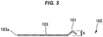
FIG. 4 andFIG. 5 , the metal gasket of this type contains a metal plate having anopening portion 102, in which aseal bead 101 having a cross-sectional shape bent in a chevron shape is formed along theopening portion 102 of the inner periphery serving as a flow passage. The metal gasket seals exhaust gas and the like passing through theopening portion 102 by the seal bead 101 (for example, see Patent Document 1). - Patent Document 1: Japanese Unexamined Patent Application Publication No.
2013-231450 -
US 2006/0103079 A1 discloses a metal gasket having four openings, four seal beads having a bent cross-sectional shape each formed along a corresponding one of the openings, and a plurality of arc shaped lightening holes extending along outer peripheries of the seal beads with a constant distance between the lightening holes and the seal beads. Some of the lightening holes are located between adjacent two of the seal beads. - Further metal gaskets having a similar configuration are known from
US 2008/073858 A1 ,JP S59 11141 U EP 1 184 608 A2JP 2001 132843 A - In the metal gasket of this type, the outer shape of a
flat plate 103 of the outer periphery of theseal bead 101 and the opening shape of theopening portion 102 are designed in conformity with the outer shape of a mating flange and the opening shape of the flow passage, and the shape and the dimension of the periphery of theseal bead 101 vary depending on specifications. Therefore, the distance from theseal bead 101 to an outerperipheral edge 103a of theflat plate 103 is not constant depending on the outer shape of theflat plate 103. In an example illustrated inFIG. 4 , for example, a dimension L2 is larger than a dimension L1. - A tensile stress generated in the
flat plate 103 of the outer periphery of theseal bead 101 in the molding of theseal bead 101 by a male mold and a female mold (not illustrated) acts so as to reduce a height h of theseal bead 101. The tensile stress becomes remarkable in a portion where the distance from theseal bead 101 to the outerperipheral edge 103a of theflat plate 103 is large, and therefore there is a concern that the height h of theseal bead 101 becomes nonuniform in the circumferential direction. - It is a technical object of the present invention to provide a metal gasket suppressing a variation in the height of a seal bead due to a tensile stress generated in a flat plate of the outer periphery of the seal bead in the molding of the seal bead and having a stable seal function.
- The object of the invention is achieved with a metal gasket having the features of
claim 1. - According to the metal gasket of the present invention, a tensile stress generated in the outer periphery by the molding of the seal bead decreases to be uniform by the lightening holes extending along the outer periphery of the seal bead, and therefore a variation in the height of the seal bead due to the tensile stress can be suppressed and a stable seal function can be performed.
-
-
FIG. 1 is a plan view illustrating an example of a metal gasket, not claimed but useful for understanding the present invention. -
FIG. 2 is a cross-sectional view along the II-II line inFIG. 1 . -
FIG. 3 is a plan view illustrating an embodiment of a metal gasket according to the present invention. -
FIG. 4 is a plan view illustrating an example of a conventional metal gasket. -
FIG. 5 is a cross-sectional view along the V-V line inFIG. 4 . - A preferable embodiment of a metal gasket is described with reference to the drawings.
FIG. 1 and FIG. 2 illustrate an example of a metal gasket not claimed but useful for understanding the invention. - The metal gasket contains a
thin metal plate 1 having moderate elasticity, such as a steel plate or an aluminum alloy. In the metal gasket, aport hole 2 located in a center portion andbolt insertion holes 3 located near the four corners on the outer periphery side of theport hole 2 are formed and aseal bead 4 is formed along the outer periphery of theport hole 2. Theport hole 2 is equivalent to the opening portion. - In detail, the
metal plate 1 is formed into an outer shape in which a pair oflong sides 1a of a rectangle having rounded corners are formed into an inwardly curved curved-line shapes symmetrical to each other and theport hole 2 is formed into a long hole shape elongating in a direction orthogonal toshort sides 1b of themetal plate 1 as illustrated inFIG. 1 . - The
seal bead 4 contains a flip-up bead, a full bead, a trapezoid bead, or a half bead, for example. The various kinds of beads are as follows as an example. In the flip-up bead, the width of aninclined surface 4a on theport hole 2 side is narrower than the width of aninclined surface 4b on the side opposite to the port hole 2 (one having a cross-sectional shape illustrated inFIG. 2 ). In the full bead, theinclined surfaces port hole 2 has a bump shape due to theinclined surface 4b on one side serving as the edge of the peak. Theseal bead 4 has a pair ofsemicircular arc portions 41 extending along the outer periphery of the opening edge of theport hole 2 and symmetrical to each other and a pair ofstraight line portions 42 extending parallel to each other between the pair ofsemicircular arc portions 41. - On the outer periphery side of the
seal bead 4, a plurality of lighteningholes 5 extending along the outer periphery of theseal bead 4 are formed. Thelightening holes 5 contain a pair of circular arc-shaped lightening holes 51 extending along thesemicircular arc portions 41 of theseal bead 4 and a pair of straight line-shaped lightening holes 52 extending along thestraight line portions 42 of theseal bead 4. The circular arc-shaped lightening holes 51 and the straight line-shaped lightening holes 52 are discontinuous from each other. In other words, an inner peripheral portion of themetal plate 1 where theseal bead 4 is formed and aflat plate 11 of themetal plate 1 on the outer periphery side relative to thelightening holes 5 are continuous to each other throughbridge portions 12 between the circular arc-shaped lightening holes 51 and the straight line-shaped lightening holes 52. - A distance (distance in the normal direction) δL between the edge on the
seal bead 4 side in thelightening hole 5 and theseal bead 4 illustrated inFIG. 2 is constant. - The metal gasket configured as described above is placed between joint surfaces facing each other in a connection portion of an exhaust system of an internal-combustion engine for automobiles, for example. At this time, the metal gasket is tightened with a plurality of bolts (not illustrated) passed through the
bolt insertion holes 3 to thereby compress and deform theseal bead 4, obtain a surface pressure required for sealing by a repulsive load thereof, and prevent the leakage of exhaust gas from between the joint surfaces. - According to the metal gasket, even when the distance from the seal bead 4 to the outer peripheral edge of the
metal plate 1 is not constant due to the fact that the outer shape of the metal plate 1 (flat plate 11) and the opening shape (plane projection shape of the seal bead 4) of theport hole 2 are noncircular, the distance δL from the outer periphery of theseal bead 4 to thelightening holes 5 is constant by the formation of the lightening holes 5 (circular arc-shaped lightening hole 51 and straight line-shaped lightening hole 52) on the outer periphery side of theseal bead 4. Therefore, the tensile stress generated on the outer periphery side of theseal bead 4 by the molding of theseal bead 4 by a male mold and a female mold (not illustrated) decreases and becomes almost uniform. The tensile stress generated in thebridge portions 12 between the circular arc-shaped lightening holes 51 and the straight line-shaped lightening holes 52 is also effectively suppressed by reducing a width W of thebridge portions 12. - Therefore, a variation in the circumferential direction of the height h of the
seal bead 4 is suppressed and a stable seal function can be performed. Moreover, the formation of thelightening holes 5 can reduce the weight of the metal gasket. -
FIG. 3 illustrates an embodiment of a metal gasket according to the present invention. - The metal gasket of this embodiment also contains a
thin metal plate 1 having moderate elasticity, such as stainless steel or an aluminum alloy, and has threecircular port holes 2 arranged in a row. In a plurality ofprojections 13 formed at predetermined intervals in an outer peripheral portion of themetal plate 1,bolt insertion holes 3 are individually formed.Seal beads 4 are formed concentrically with theport holes 2 along the outer periphery of theport holes 2. Lighteningholes 5 are located between theseal beads 4 formed in the periphery of theport holes 2 and are formed into a circular arc shape extending along the outer periphery of theseal beads 4. - Also in this embodiment, a tensile stress generated on the outer periphery side of the
seal bead 4 can be reduced and can be made almost uniform by the formation of thelightening holes 5. As a result, a variation in the height of theseal beads 4 can be suppressed and a stable seal function can be performed. -
- 1
- metal plate
- 11
- flat plate
- 2
- port hole (opening portion)
- 3
- bolt insertion hole
- 4
- seal bead
- 5
- lightening hole
Claims (1)
- A metal gasket comprising:a metal plate (1) having three opening portions (2); only three seal beads (4) having a bent cross-sectional shape each formed along a corresponding one of the opening portions (2); only four circular arc shaped lightening holes (5) extending along outer peripheries of the seal beads (4) with a constant distance between the lightening holes (5) and the seal beads (4), andeach of the lightening holes (5) being located between adjacent two of the seal beads (4).
Applications Claiming Priority (2)
| Application Number | Priority Date | Filing Date | Title |
|---|---|---|---|
| JP2016252407 | 2016-12-27 | ||
| PCT/JP2017/037446 WO2018123214A1 (en) | 2016-12-27 | 2017-10-17 | Metal gasket |
Publications (3)
| Publication Number | Publication Date |
|---|---|
| EP3564559A1 EP3564559A1 (en) | 2019-11-06 |
| EP3564559A4 EP3564559A4 (en) | 2019-12-18 |
| EP3564559B1 true EP3564559B1 (en) | 2020-12-16 |
Family
ID=62710190
Family Applications (1)
| Application Number | Title | Priority Date | Filing Date |
|---|---|---|---|
| EP17887594.4A Active EP3564559B1 (en) | 2016-12-27 | 2017-10-17 | Metal gasket |
Country Status (5)
| Country | Link |
|---|---|
| US (1) | US11156293B2 (en) |
| EP (1) | EP3564559B1 (en) |
| JP (1) | JP6855506B2 (en) |
| CN (1) | CN110325770B (en) |
| WO (1) | WO2018123214A1 (en) |
Families Citing this family (1)
| Publication number | Priority date | Publication date | Assignee | Title |
|---|---|---|---|---|
| US11898521B1 (en) * | 2023-07-10 | 2024-02-13 | Martin Rodriguez | Exhaust manifold gasket device |
Family Cites Families (25)
| Publication number | Priority date | Publication date | Assignee | Title |
|---|---|---|---|---|
| US2699349A (en) * | 1952-09-23 | 1955-01-11 | Clarence S Brownlee | Gasket |
| US4213620A (en) * | 1978-12-20 | 1980-07-22 | General Motors Corporation | Cylinder head gasket |
| JPS5911141U (en) * | 1982-07-12 | 1984-01-24 | ソ−ワ工業株式会社 | metal gasket |
| JPS61158360A (en) | 1984-12-29 | 1986-07-18 | Olympus Optical Co Ltd | Picture formation device |
| JPS63158360A (en) * | 1986-12-19 | 1988-07-01 | Honda Motor Co Ltd | Metal gasket for internal combustion engine |
| JPH0521653Y2 (en) * | 1988-07-09 | 1993-06-03 | ||
| US5267740A (en) * | 1992-02-20 | 1993-12-07 | Fel-Pro Incorporated | Metal head gasket with integrated sealing aids |
| JPH09292027A (en) | 1996-04-30 | 1997-11-11 | Nippon Reinz Co Ltd | Metal gasket |
| US5853175A (en) * | 1996-09-30 | 1998-12-29 | Ishikawa Gasket Co., Ltd. | Cylinder head gasket with fluid flow path |
| JPH10184916A (en) * | 1996-12-20 | 1998-07-14 | Nippon Gasket Co Ltd | Metallic gasket |
| JP2000097340A (en) | 1998-09-21 | 2000-04-04 | Ishino Gasket Kogyo Kk | Metal cylinder head gasket with interbore slit |
| JP3177841B2 (en) * | 1999-09-08 | 2001-06-18 | 石川ガスケット株式会社 | Cylinder head gasket |
| JP3569179B2 (en) * | 1999-11-05 | 2004-09-22 | 石川ガスケット株式会社 | Metal gasket |
| JP2001280502A (en) * | 2000-03-29 | 2001-10-10 | Nippon Gasket Co Ltd | Single-layer metal gasket |
| JP2002081543A (en) * | 2000-09-04 | 2002-03-22 | Nippon Gasket Co Ltd | Metal gasket |
| DE102004054712B4 (en) * | 2004-11-12 | 2007-02-01 | Elringklinger Ag | Cylinder head gasket |
| DE102004054709B4 (en) * | 2004-11-12 | 2007-11-15 | Elringklinger Ag | Cylinder head gasket |
| JP4476940B2 (en) * | 2006-01-16 | 2010-06-09 | 石川ガスケット株式会社 | Cylinder head gasket |
| DE102006045587A1 (en) * | 2006-09-27 | 2008-04-03 | Elringklinger Ag | sealing arrangement |
| DE102009037703A1 (en) * | 2009-03-05 | 2010-09-09 | Federal-Mogul Sealing Systems Gmbh | Flat seal i.e. exhaust gas-side seal, for use as exhaust flange seal for internal combustion engine, has lugs projecting with respect to base area, where carrier element and/or sealing element is provided with partially raised regions |
| JP5359770B2 (en) | 2009-10-21 | 2013-12-04 | 日本ガスケット株式会社 | Cylinder head gasket |
| JP5783355B2 (en) * | 2011-03-08 | 2015-09-24 | Nok株式会社 | Gasket seal bead structure |
| JP6274384B2 (en) * | 2012-04-27 | 2018-02-07 | Nok株式会社 | Metal gasket and manufacturing method thereof |
| JP2018071730A (en) * | 2016-11-02 | 2018-05-10 | Nok株式会社 | gasket |
| DE102017119307A1 (en) * | 2017-08-23 | 2019-02-28 | Elringklinger Ag | Cylinder head gasket |
-
2017
- 2017-10-17 CN CN201780071335.4A patent/CN110325770B/en active Active
- 2017-10-17 WO PCT/JP2017/037446 patent/WO2018123214A1/en unknown
- 2017-10-17 US US16/465,593 patent/US11156293B2/en active Active
- 2017-10-17 EP EP17887594.4A patent/EP3564559B1/en active Active
- 2017-10-17 JP JP2018558841A patent/JP6855506B2/en active Active
Non-Patent Citations (1)
| Title |
|---|
| None * |
Also Published As
| Publication number | Publication date |
|---|---|
| US20190383231A1 (en) | 2019-12-19 |
| JPWO2018123214A1 (en) | 2019-10-31 |
| WO2018123214A1 (en) | 2018-07-05 |
| EP3564559A1 (en) | 2019-11-06 |
| US11156293B2 (en) | 2021-10-26 |
| CN110325770A (en) | 2019-10-11 |
| JP6855506B2 (en) | 2021-04-07 |
| EP3564559A4 (en) | 2019-12-18 |
| CN110325770B (en) | 2021-01-08 |
Similar Documents
| Publication | Publication Date | Title |
|---|---|---|
| EP2843268B1 (en) | Metal gasket and manufacturing method therefor | |
| US4088347A (en) | Sealing arrangement | |
| US20160223085A1 (en) | Metal gasket | |
| US7665741B2 (en) | Laminate-type gasket | |
| US10113505B2 (en) | Gasket and engine with the gasket | |
| US6478307B2 (en) | Metal gasket | |
| KR100739500B1 (en) | Cylinder head gasket | |
| US7753378B2 (en) | Cylinder head gasket | |
| EP3564559B1 (en) | Metal gasket | |
| EP2681470B1 (en) | Cylinder head gasket | |
| JP2001032937A (en) | Single level metal gasket | |
| JP4056503B2 (en) | Metal gasket | |
| JP3200662U (en) | Metal gasket | |
| EP3105475B1 (en) | Cylinder head gasket with compression control features | |
| JP2789798B2 (en) | Metal cylinder head gasket | |
| JP2008223581A (en) | Metal gasket | |
| JP2004239369A (en) | Metallic gasket | |
| JP4286346B2 (en) | Metal gasket | |
| EP4343178A1 (en) | Gasket | |
| JP4036284B2 (en) | Metal gasket | |
| JP6666584B2 (en) | Seal structure | |
| JP2501590Y2 (en) | Metal gasket | |
| JPH03186668A (en) | Metal gasket | |
| JPH04128571U (en) | split gasket |
Legal Events
| Date | Code | Title | Description |
|---|---|---|---|
| STAA | Information on the status of an ep patent application or granted ep patent |
Free format text: STATUS: THE INTERNATIONAL PUBLICATION HAS BEEN MADE |
|
| PUAI | Public reference made under article 153(3) epc to a published international application that has entered the european phase |
Free format text: ORIGINAL CODE: 0009012 |
|
| STAA | Information on the status of an ep patent application or granted ep patent |
Free format text: STATUS: REQUEST FOR EXAMINATION WAS MADE |
|
| 17P | Request for examination filed |
Effective date: 20190425 |
|
| AK | Designated contracting states |
Kind code of ref document: A1 Designated state(s): AL AT BE BG CH CY CZ DE DK EE ES FI FR GB GR HR HU IE IS IT LI LT LU LV MC MK MT NL NO PL PT RO RS SE SI SK SM TR |
|
| AX | Request for extension of the european patent |
Extension state: BA ME |
|
| A4 | Supplementary search report drawn up and despatched |
Effective date: 20191115 |
|
| RIC1 | Information provided on ipc code assigned before grant |
Ipc: F16J 15/08 20060101AFI20191111BHEP Ipc: F01N 13/18 20100101ALI20191111BHEP Ipc: F02F 11/00 20060101ALI20191111BHEP |
|
| DAV | Request for validation of the european patent (deleted) | ||
| DAX | Request for extension of the european patent (deleted) | ||
| GRAP | Despatch of communication of intention to grant a patent |
Free format text: ORIGINAL CODE: EPIDOSNIGR1 |
|
| STAA | Information on the status of an ep patent application or granted ep patent |
Free format text: STATUS: GRANT OF PATENT IS INTENDED |
|
| RIC1 | Information provided on ipc code assigned before grant |
Ipc: F01N 13/18 20100101ALI20200616BHEP Ipc: F16J 15/08 20060101AFI20200616BHEP Ipc: F02F 11/00 20060101ALI20200616BHEP |
|
| INTG | Intention to grant announced |
Effective date: 20200707 |
|
| GRAS | Grant fee paid |
Free format text: ORIGINAL CODE: EPIDOSNIGR3 |
|
| GRAA | (expected) grant |
Free format text: ORIGINAL CODE: 0009210 |
|
| STAA | Information on the status of an ep patent application or granted ep patent |
Free format text: STATUS: THE PATENT HAS BEEN GRANTED |
|
| AK | Designated contracting states |
Kind code of ref document: B1 Designated state(s): AL AT BE BG CH CY CZ DE DK EE ES FI FR GB GR HR HU IE IS IT LI LT LU LV MC MK MT NL NO PL PT RO RS SE SI SK SM TR |
|
| REG | Reference to a national code |
Ref country code: GB Ref legal event code: FG4D |
|
| REG | Reference to a national code |
Ref country code: IE Ref legal event code: FG4D |
|
| REG | Reference to a national code |
Ref country code: DE Ref legal event code: R096 Ref document number: 602017029829 Country of ref document: DE |
|
| REG | Reference to a national code |
Ref country code: AT Ref legal event code: REF Ref document number: 1345898 Country of ref document: AT Kind code of ref document: T Effective date: 20210115 |
|
| PG25 | Lapsed in a contracting state [announced via postgrant information from national office to epo] |
Ref country code: GR Free format text: LAPSE BECAUSE OF FAILURE TO SUBMIT A TRANSLATION OF THE DESCRIPTION OR TO PAY THE FEE WITHIN THE PRESCRIBED TIME-LIMIT Effective date: 20210317 Ref country code: NO Free format text: LAPSE BECAUSE OF FAILURE TO SUBMIT A TRANSLATION OF THE DESCRIPTION OR TO PAY THE FEE WITHIN THE PRESCRIBED TIME-LIMIT Effective date: 20210316 Ref country code: RS Free format text: LAPSE BECAUSE OF FAILURE TO SUBMIT A TRANSLATION OF THE DESCRIPTION OR TO PAY THE FEE WITHIN THE PRESCRIBED TIME-LIMIT Effective date: 20201216 Ref country code: FI Free format text: LAPSE BECAUSE OF FAILURE TO SUBMIT A TRANSLATION OF THE DESCRIPTION OR TO PAY THE FEE WITHIN THE PRESCRIBED TIME-LIMIT Effective date: 20201216 |
|
| REG | Reference to a national code |
Ref country code: AT Ref legal event code: MK05 Ref document number: 1345898 Country of ref document: AT Kind code of ref document: T Effective date: 20201216 |
|
| REG | Reference to a national code |
Ref country code: NL Ref legal event code: MP Effective date: 20201216 |
|
| PG25 | Lapsed in a contracting state [announced via postgrant information from national office to epo] |
Ref country code: LV Free format text: LAPSE BECAUSE OF FAILURE TO SUBMIT A TRANSLATION OF THE DESCRIPTION OR TO PAY THE FEE WITHIN THE PRESCRIBED TIME-LIMIT Effective date: 20201216 Ref country code: SE Free format text: LAPSE BECAUSE OF FAILURE TO SUBMIT A TRANSLATION OF THE DESCRIPTION OR TO PAY THE FEE WITHIN THE PRESCRIBED TIME-LIMIT Effective date: 20201216 Ref country code: BG Free format text: LAPSE BECAUSE OF FAILURE TO SUBMIT A TRANSLATION OF THE DESCRIPTION OR TO PAY THE FEE WITHIN THE PRESCRIBED TIME-LIMIT Effective date: 20210316 |
|
| PG25 | Lapsed in a contracting state [announced via postgrant information from national office to epo] |
Ref country code: NL Free format text: LAPSE BECAUSE OF FAILURE TO SUBMIT A TRANSLATION OF THE DESCRIPTION OR TO PAY THE FEE WITHIN THE PRESCRIBED TIME-LIMIT Effective date: 20201216 Ref country code: HR Free format text: LAPSE BECAUSE OF FAILURE TO SUBMIT A TRANSLATION OF THE DESCRIPTION OR TO PAY THE FEE WITHIN THE PRESCRIBED TIME-LIMIT Effective date: 20201216 |
|
| REG | Reference to a national code |
Ref country code: LT Ref legal event code: MG9D |
|
| PG25 | Lapsed in a contracting state [announced via postgrant information from national office to epo] |
Ref country code: PT Free format text: LAPSE BECAUSE OF FAILURE TO SUBMIT A TRANSLATION OF THE DESCRIPTION OR TO PAY THE FEE WITHIN THE PRESCRIBED TIME-LIMIT Effective date: 20210416 Ref country code: RO Free format text: LAPSE BECAUSE OF FAILURE TO SUBMIT A TRANSLATION OF THE DESCRIPTION OR TO PAY THE FEE WITHIN THE PRESCRIBED TIME-LIMIT Effective date: 20201216 Ref country code: SK Free format text: LAPSE BECAUSE OF FAILURE TO SUBMIT A TRANSLATION OF THE DESCRIPTION OR TO PAY THE FEE WITHIN THE PRESCRIBED TIME-LIMIT Effective date: 20201216 Ref country code: SM Free format text: LAPSE BECAUSE OF FAILURE TO SUBMIT A TRANSLATION OF THE DESCRIPTION OR TO PAY THE FEE WITHIN THE PRESCRIBED TIME-LIMIT Effective date: 20201216 Ref country code: LT Free format text: LAPSE BECAUSE OF FAILURE TO SUBMIT A TRANSLATION OF THE DESCRIPTION OR TO PAY THE FEE WITHIN THE PRESCRIBED TIME-LIMIT Effective date: 20201216 Ref country code: EE Free format text: LAPSE BECAUSE OF FAILURE TO SUBMIT A TRANSLATION OF THE DESCRIPTION OR TO PAY THE FEE WITHIN THE PRESCRIBED TIME-LIMIT Effective date: 20201216 Ref country code: CZ Free format text: LAPSE BECAUSE OF FAILURE TO SUBMIT A TRANSLATION OF THE DESCRIPTION OR TO PAY THE FEE WITHIN THE PRESCRIBED TIME-LIMIT Effective date: 20201216 |
|
| PG25 | Lapsed in a contracting state [announced via postgrant information from national office to epo] |
Ref country code: AT Free format text: LAPSE BECAUSE OF FAILURE TO SUBMIT A TRANSLATION OF THE DESCRIPTION OR TO PAY THE FEE WITHIN THE PRESCRIBED TIME-LIMIT Effective date: 20201216 Ref country code: PL Free format text: LAPSE BECAUSE OF FAILURE TO SUBMIT A TRANSLATION OF THE DESCRIPTION OR TO PAY THE FEE WITHIN THE PRESCRIBED TIME-LIMIT Effective date: 20201216 |
|
| REG | Reference to a national code |
Ref country code: DE Ref legal event code: R097 Ref document number: 602017029829 Country of ref document: DE |
|
| PG25 | Lapsed in a contracting state [announced via postgrant information from national office to epo] |
Ref country code: IS Free format text: LAPSE BECAUSE OF FAILURE TO SUBMIT A TRANSLATION OF THE DESCRIPTION OR TO PAY THE FEE WITHIN THE PRESCRIBED TIME-LIMIT Effective date: 20210416 |
|
| PLBE | No opposition filed within time limit |
Free format text: ORIGINAL CODE: 0009261 |
|
| STAA | Information on the status of an ep patent application or granted ep patent |
Free format text: STATUS: NO OPPOSITION FILED WITHIN TIME LIMIT |
|
| PG25 | Lapsed in a contracting state [announced via postgrant information from national office to epo] |
Ref country code: IT Free format text: LAPSE BECAUSE OF FAILURE TO SUBMIT A TRANSLATION OF THE DESCRIPTION OR TO PAY THE FEE WITHIN THE PRESCRIBED TIME-LIMIT Effective date: 20201216 Ref country code: AL Free format text: LAPSE BECAUSE OF FAILURE TO SUBMIT A TRANSLATION OF THE DESCRIPTION OR TO PAY THE FEE WITHIN THE PRESCRIBED TIME-LIMIT Effective date: 20201216 |
|
| 26N | No opposition filed |
Effective date: 20210917 |
|
| PG25 | Lapsed in a contracting state [announced via postgrant information from national office to epo] |
Ref country code: DK Free format text: LAPSE BECAUSE OF FAILURE TO SUBMIT A TRANSLATION OF THE DESCRIPTION OR TO PAY THE FEE WITHIN THE PRESCRIBED TIME-LIMIT Effective date: 20201216 |
|
| PG25 | Lapsed in a contracting state [announced via postgrant information from national office to epo] |
Ref country code: ES Free format text: LAPSE BECAUSE OF FAILURE TO SUBMIT A TRANSLATION OF THE DESCRIPTION OR TO PAY THE FEE WITHIN THE PRESCRIBED TIME-LIMIT Effective date: 20201216 |
|
| PG25 | Lapsed in a contracting state [announced via postgrant information from national office to epo] |
Ref country code: SI Free format text: LAPSE BECAUSE OF FAILURE TO SUBMIT A TRANSLATION OF THE DESCRIPTION OR TO PAY THE FEE WITHIN THE PRESCRIBED TIME-LIMIT Effective date: 20201216 |
|
| REG | Reference to a national code |
Ref country code: CH Ref legal event code: PL |
|
| PG25 | Lapsed in a contracting state [announced via postgrant information from national office to epo] |
Ref country code: IS Free format text: LAPSE BECAUSE OF FAILURE TO SUBMIT A TRANSLATION OF THE DESCRIPTION OR TO PAY THE FEE WITHIN THE PRESCRIBED TIME-LIMIT Effective date: 20210416 |
|
| REG | Reference to a national code |
Ref country code: BE Ref legal event code: MM Effective date: 20211031 |
|
| PG25 | Lapsed in a contracting state [announced via postgrant information from national office to epo] |
Ref country code: MC Free format text: LAPSE BECAUSE OF FAILURE TO SUBMIT A TRANSLATION OF THE DESCRIPTION OR TO PAY THE FEE WITHIN THE PRESCRIBED TIME-LIMIT Effective date: 20201216 |
|
| PG25 | Lapsed in a contracting state [announced via postgrant information from national office to epo] |
Ref country code: LU Free format text: LAPSE BECAUSE OF NON-PAYMENT OF DUE FEES Effective date: 20211017 Ref country code: BE Free format text: LAPSE BECAUSE OF NON-PAYMENT OF DUE FEES Effective date: 20211031 |
|
| PG25 | Lapsed in a contracting state [announced via postgrant information from national office to epo] |
Ref country code: LI Free format text: LAPSE BECAUSE OF NON-PAYMENT OF DUE FEES Effective date: 20211031 Ref country code: CH Free format text: LAPSE BECAUSE OF NON-PAYMENT OF DUE FEES Effective date: 20211031 |
|
| PG25 | Lapsed in a contracting state [announced via postgrant information from national office to epo] |
Ref country code: IE Free format text: LAPSE BECAUSE OF NON-PAYMENT OF DUE FEES Effective date: 20211017 |
|
| PG25 | Lapsed in a contracting state [announced via postgrant information from national office to epo] |
Ref country code: CY Free format text: LAPSE BECAUSE OF FAILURE TO SUBMIT A TRANSLATION OF THE DESCRIPTION OR TO PAY THE FEE WITHIN THE PRESCRIBED TIME-LIMIT Effective date: 20201216 |
|
| PG25 | Lapsed in a contracting state [announced via postgrant information from national office to epo] |
Ref country code: HU Free format text: LAPSE BECAUSE OF FAILURE TO SUBMIT A TRANSLATION OF THE DESCRIPTION OR TO PAY THE FEE WITHIN THE PRESCRIBED TIME-LIMIT; INVALID AB INITIO Effective date: 20171017 |
|
| PGFP | Annual fee paid to national office [announced via postgrant information from national office to epo] |
Ref country code: GB Payment date: 20230831 Year of fee payment: 7 |
|
| PGFP | Annual fee paid to national office [announced via postgrant information from national office to epo] |
Ref country code: FR Payment date: 20230911 Year of fee payment: 7 |
|
| PGFP | Annual fee paid to national office [announced via postgrant information from national office to epo] |
Ref country code: DE Payment date: 20230830 Year of fee payment: 7 |