EP2843268B1 - Metal gasket and manufacturing method therefor - Google Patents
Metal gasket and manufacturing method therefor Download PDFInfo
- Publication number
- EP2843268B1 EP2843268B1 EP13782462.9A EP13782462A EP2843268B1 EP 2843268 B1 EP2843268 B1 EP 2843268B1 EP 13782462 A EP13782462 A EP 13782462A EP 2843268 B1 EP2843268 B1 EP 2843268B1
- Authority
- EP
- European Patent Office
- Prior art keywords
- bead
- metal plate
- flip
- forming
- metal gasket
- Prior art date
- Legal status (The legal status is an assumption and is not a legal conclusion. Google has not performed a legal analysis and makes no representation as to the accuracy of the status listed.)
- Active
Links
Images


Classifications
-
- F—MECHANICAL ENGINEERING; LIGHTING; HEATING; WEAPONS; BLASTING
- F02—COMBUSTION ENGINES; HOT-GAS OR COMBUSTION-PRODUCT ENGINE PLANTS
- F02F—CYLINDERS, PISTONS OR CASINGS, FOR COMBUSTION ENGINES; ARRANGEMENTS OF SEALINGS IN COMBUSTION ENGINES
- F02F11/00—Arrangements of sealings in combustion engines
-
- B—PERFORMING OPERATIONS; TRANSPORTING
- B21—MECHANICAL METAL-WORKING WITHOUT ESSENTIALLY REMOVING MATERIAL; PUNCHING METAL
- B21D—WORKING OR PROCESSING OF SHEET METAL OR METAL TUBES, RODS OR PROFILES WITHOUT ESSENTIALLY REMOVING MATERIAL; PUNCHING METAL
- B21D22/00—Shaping without cutting, by stamping, spinning, or deep-drawing
- B21D22/02—Stamping using rigid devices or tools
-
- B—PERFORMING OPERATIONS; TRANSPORTING
- B21—MECHANICAL METAL-WORKING WITHOUT ESSENTIALLY REMOVING MATERIAL; PUNCHING METAL
- B21D—WORKING OR PROCESSING OF SHEET METAL OR METAL TUBES, RODS OR PROFILES WITHOUT ESSENTIALLY REMOVING MATERIAL; PUNCHING METAL
- B21D35/00—Combined processes according to or processes combined with methods covered by groups B21D1/00 - B21D31/00
- B21D35/001—Shaping combined with punching, e.g. stamping and perforating
-
- F—MECHANICAL ENGINEERING; LIGHTING; HEATING; WEAPONS; BLASTING
- F02—COMBUSTION ENGINES; HOT-GAS OR COMBUSTION-PRODUCT ENGINE PLANTS
- F02F—CYLINDERS, PISTONS OR CASINGS, FOR COMBUSTION ENGINES; ARRANGEMENTS OF SEALINGS IN COMBUSTION ENGINES
- F02F11/00—Arrangements of sealings in combustion engines
- F02F11/002—Arrangements of sealings in combustion engines involving cylinder heads
-
- F—MECHANICAL ENGINEERING; LIGHTING; HEATING; WEAPONS; BLASTING
- F16—ENGINEERING ELEMENTS AND UNITS; GENERAL MEASURES FOR PRODUCING AND MAINTAINING EFFECTIVE FUNCTIONING OF MACHINES OR INSTALLATIONS; THERMAL INSULATION IN GENERAL
- F16J—PISTONS; CYLINDERS; SEALINGS
- F16J15/00—Sealings
- F16J15/02—Sealings between relatively-stationary surfaces
- F16J15/06—Sealings between relatively-stationary surfaces with solid packing compressed between sealing surfaces
- F16J15/08—Sealings between relatively-stationary surfaces with solid packing compressed between sealing surfaces with exclusively metal packing
- F16J15/0818—Flat gaskets
-
- F—MECHANICAL ENGINEERING; LIGHTING; HEATING; WEAPONS; BLASTING
- F01—MACHINES OR ENGINES IN GENERAL; ENGINE PLANTS IN GENERAL; STEAM ENGINES
- F01N—GAS-FLOW SILENCERS OR EXHAUST APPARATUS FOR MACHINES OR ENGINES IN GENERAL; GAS-FLOW SILENCERS OR EXHAUST APPARATUS FOR INTERNAL COMBUSTION ENGINES
- F01N13/00—Exhaust or silencing apparatus characterised by constructional features ; Exhaust or silencing apparatus, or parts thereof, having pertinent characteristics not provided for in, or of interest apart from, groups F01N1/00 - F01N5/00, F01N9/00, F01N11/00
- F01N13/18—Construction facilitating manufacture, assembly, or disassembly
- F01N13/1805—Fixing exhaust manifolds, exhaust pipes or pipe sections to each other, to engine or to vehicle body
- F01N13/1827—Sealings specially adapted for exhaust systems
Definitions
- the present invention relates to a metal gasket which is used as a seal means of a joint portion between an exhaust manifold and an exhaust pipe of an internal combustion engine and a joint portion between a cylinder block and a cylinder head, and a manufacturing method of the metal gasket.
- a metal gasket which is used as a seal means of a joint portion between an exhaust manifold and an exhaust pipe of an internal combustion engine or between an intake manifold and an intake pipe is pinched between joint surfaces which faces to each other, and is structured such as to seal exhaust gas and air-fuel mixture of air and fuel by a seal bead which is bending formed so as to surround an opening portion which is open to the joint surface.
- an opening shape in the joint portion in relation to the exhaust pipe or the intake pipe is non-circular shapes (for example, a rectangular ring shape), and a metal gasket having a seal bead formed into a similar shape to the opening shape is used in this portion (refer, for example, to patent document 1).
- the metal gasket tends to deform in a portion in which the seal bead extends linearly rather than a portion extending like a curve, when the metal gasket is exposed to a fastening load. Accordingly, there is a problem that leakage tends to be generated in the linear portion of the seal bead due to lack of surface pressure.
- the present invention is made by taking the points mentioned above into consideration, and a technical object of the present invention is to provide a metal gasket which can secure an excellent sealing performance over a long period of time by suppressing partial reduction of the surface pressure of the seal bead.
- a metal gasket comprising:
- half bead here is a protruding shaped bead which forms an end edge of a ridge portion in an opening edge portion of the metal plate and is constructed by a one-side inclined surface
- the flip-up bead is a protruding shaped bead which runs to the other inclined surface portion from one bottom portion via one inclined surface portion and the ridge portion
- the full bead is a protruding shaped bead which is formed like a chevron shape in its cross sectional shape, and runs to the other bottom portion from one bottom portion via one inclined surface portion, the ridge portion and the other inclined surface portion.
- spring constant of the seal bead when a fastening load is applied is higher in the portion constructed by the flip-up bead than in the portion constructed by the half bread, and is higher in the portion constructed by the full bead than in the portion constructed by the flip-up bead.
- a manufacturing method of a metal gasket comprising:
- a manufacturing method of a metal gasket comprising:
- the bead formed in the metal plate by the concave mold and the convex mold comes to the half bead in the portion in which the opening edge of the opening portion passes through the ridge portion of the bead, comes to the flip-up bead in the portion in which the opening edge of the opening portion passes through the inclined surface portion of the bead, and comes to the full bead in the portion in which the opening edge of the opening portion passes through the bottom portion of the bead.
- the spring constant of the seal bead greatly changes among the portion constructed by the half bead, the portion constructed by the flip-up bead and the portion constructed by the full bead. Therefore, an excellent sealing performance can be secured over a long period of time by suppressing dispersion of the surface pressure of the seal bead due to difference in curvature in the case that the seal bead extends non-circularly.
- Fig. 1 shows the preferable embodiment of the metal gasket according to the present invention, and the metal gasket MG is structured, for example, such as to be interposed between an exhaust manifold of an automotive internal combustion engine and a joint surface of an exhaust pipe.
- the metal plate MG is structured such that a port hole portion 2 and a plurality of bolt insertion holes 3 are provided in a metal plate 1, and a seal bead 4 extending along a periphery of the port hole portion 2 is formed.
- the mental plate 1 is constructed by a thin plate which is selected from a stainless steel, a cold-rolled steel, a galvanized sheet iron and an aluminum alloy plate and has an elasticity.
- the bolt insertion holes 3 are arranged at a plurality of positions between the port hole portion 2 and an outer peripheral edge of the metal plate 1 and are provided for inserting bolts connecting an exhaust manifold and an exhaust pipe which are not shown.
- the port hole portion 2 corresponds to the opening portion described in the first to third aspects, and is formed into a projection geometry of an exhaust gas passage which is constructed by the exhaust manifold and the exhaust pipe, in other words, an approximately oval shape obtained by projecting an opening shape of the exhaust gas passage which is open to joint surfaces of the exhaust manifold and the exhaust pipe.
- an opening edge of the port hole portion 2 is constructed by a pair of semicircular arc shaped opening edges 2a, and a linear opening edge 2b and a gentle curve shaped opening edge 2c which extend between the semicircular arc shaped opening edges 2a.
- the gentle curve shaped opening edge 2c is structured such as to have much smaller curvature (greater radius of curvature) in comparison with the semicircular arc shaped opening edge 2a.
- the seal bead 4 extending along the periphery of the port hole portion 2 is constructed by a half bead 41 in a portion which is along the semicircular arc shaped opening edge 2a, and is constructed by a flip-up bead 42 in a portion which is along the linear opening edge 2b and the gentle curve shaped opening edge 2c.
- the half bead 41 is formed into a protruding shape which runs to a tabular ridge portion 4c from an outer peripheral bottom portion 4a via a diagonally uprising outer periphery inclined surface portion 4b, as shown in Fig. 2A showing a cross section along a line A-A in Fig. 1 , and an end edge in an inner peripheral side of the ridge portion 4c comes to the semicircular arc shaped opening edge 2a in the port hole portion 2.
- the flip-up bead 42 is formed into a protruding shape which runs to an inner periphery inclined surface portion 4d in an opposite side to the outer periphery inclined surface portion 4b via the outer periphery inclined surface portion 4b uprising diagonally from the outer periphery bottom portion 4a, and the ridge portion 4c which is bent like a convex shape to an upper side in an upper end of the outer periphery inclined surface portion 4b, as shown in Fig. 2B showing a cross section along a line B-B in Fig. 1 , and an inner peripheral end edge of the inner periphery inclined surface portion 4d comes to the linear opening edge 2b or the gentle curve shaped opening edge 2c in the port hole portion 2 of the metal plate 1.
- the seal bead 4 continuously transits from the half bead 41 to the flip-up bead 42 (from the flip-up bead 42 to the half bead 41).
- the metal gasket MG constructed as mentioned above is interposed, for example, between the exhaust manifold of the automotive internal combustion engine and the joint surface of the exhaust pipe singly or in a state in which a plurality of metal gaskets are laminated, the seal bead 4 is compression deformed by fastening the metal gasket MG, and the surface pressure required for sealing is obtained by a repulsive load, thereby preventing the exhaust gas from leaking from the portion between the joint surfaces.
- Figs. 3 to 10 show a method for manufacturing the metal gasket MG mentioned above according to a process sequence.
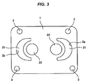
- the process first of all forms the bolt insertion hole 3, a pair of preliminary holes 21 having a portion in which the opening edge comes to the semicircular arc shaped opening edge 2a in the port hole portion 2 in Fig. 1 , and a pair of positioning holes 22, in the metal plate 1, as shown in Fig. 3 .
- These elements can be formed by punching at the same time of punching an outer edge of the metal plate 1.
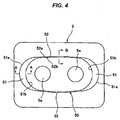
- a convex mold 5 shown in Fig. 4 is structured such that a bead forming convex portion 50 and a plurality of positioning convex portions 5a are formed on its upper surface, the positioning convex portions 5a being provided for positioning and setting the metal plate 1 on the upper surface by being fitted to the positioning holes 22 of the metal plate 1.
- the bead forming convex portion 50 corresponds to the ridge portion 4c of the seal bead 4 shown in Fig.
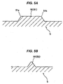
- a half bead forming convex portion 51 which forms the half bead 41 and a portion (hereinafter, refer to as a flip-up bead forming convex portion) 52 which forms the flip-up bead 42, and the half bead forming convex portion 51 is formed to be wider than the flip-up bead forming convex portion 52 as shown in Figs. 5A and 5B .
- the half bead forming convex portion 51 is formed into a crescent shape, an outer edge 51 a thereof extends in correspondence to an outer edge of the ridge portion 41 c of the half bead 41, that is, the outer edge 51 a is formed so as to be positioned in an outer peripheral side of the preliminary hole 21 in the case that the metal plate 1 shown in Fig. 3 is set to the convex mold 5, and an inner edge 51 b is on the contrary formed so as to pass through an inner side of the preliminary hole 21.
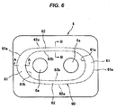
- a convex mold 6 shown in Fig. 6 is structured such that a bead forming concave portion 60 is formed in its lower surface.
- Reference symbol 6a denotes a positioning concave portion or hole which can be fitted to the positioning convex portion 5a of the convex mold 5.
- the bead forming concave portion 60 is constructed by a portion (hereinafter, refer to as a half bead forming concave portion) 61 which formed the half bead 41 of the seal bead 4 shown in Fig.
- a flip-up bead forming concave portion 62 which forms the flip-up bead 42
- the half bead forming concave portion 61 is formed to be wider than the flip-up bead forming concave portion 62, as shown in Figs. 7A and 7B .
- the half bead forming concave portion 61 is formed to be wider than the half bead forming convex portion 51 of the convex mold 5
- the flip-up bead forming concave portion 62 is formed to be wider than the flip-up bead forming convex portion 52 of the concave mold 5.
- an outer edge 61 a of the hold bead forming concave portion 61 and an outer edge 62a of the flip-up bead forming concave portion 62 in the concave mold 6 are structured such as to extend in correspondence to the bottom portion 4a of the seal bead 4 shown in Figs. 1 and 2 , and are positioned closer to an outer peripheral side than the outer edge 51 a of the half bead forming convex portion 51 and the outer edge 52a of the flip-up bead forming convex portion 52 in the convex mold 5, in the case of being combined with the convex mold 5.
- an inner edge 61 b of the half bead forming concave portion 61 and an inner edge 62b of the flip-up bead forming concave portion 62 in the concave mold 6 are positioned closer to an inner peripheral side than the inner edge 51 b of the half bead forming convex portion 51 and the inner edge 52b of the flip-up bead forming convex portion 52 in the convex mold 5, in the case of being combined with the convex mold 5.
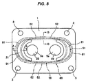
- the metal plate 1 shown in Fig. 3 is positioned and set between the convex mold 5 and the concave mold 6 so as to be press molded as shown in Figs. 8 and 9 , the metal plate 1 is bent only in the outer edge 51 a of the half bead forming convex portion 51 and the outer edge 61 a of the half bead forming concave portion 61 as shown in Fig. 9A , between the half bead forming convex portion 51 and the half bead forming concave portion 61 on the basis of existence of the preliminary hole 21. As a result, the half bead 41 is formed along the semicircular arc shaped opening edge 2a of the preliminary hole 21.
- the metal plate 1 is bent at three positions including the ridge portion of the flip-up bead forming concave portion 52, and the outer edge 62a and the inner edge 62b of the flip-up bead forming concave portion 62 as shown in Fig. 9B .
- a full bead 42' having a chevron cross sectional shape is formed.
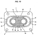
- the metal plate 1 in which the seal bead constructed by the half bead 41 and the full bead 42' is formed is cut as shown by a single-dot chain line in Fig. 10 .
- an area (an area shown by hatching in Fig. 10 ) 1 a surrounded by a pair of preliminary holes 21 and the full beads 42' and 42' is punched.
- the port hole portion 2 is formed and the flip-up bead 42 is formed along the linear opening edge 2b and the gentle curve shaped opening edge 2c of the port hole portion 2, as shown in Fig. 1 , by cutting the inner periphery inclined surface portion 4d in the full bead 42' shown in Fig. 9B at a position closer to a inner periphery bottom portion 4e, and the manufacturing of the metal gasket MG is finished.
- the metal gasket MG having the seal bead 4 in which the half beads 41 and the flip-up beads 42 are continuously provided, the half beads 41 being along the semicircular arc shaped opening edges 2a of the port hole portion, 2, and the flip-up beads 42 being along the linear opening edge 2b and the gentle curve shaped opening edge 2c.
- the portion of the flip-up bead 42 along the linear opening edge 2b and the gentle curve shaped opening edge 2c is constructed by the flip-up bead, in a relationship between shapes of the convex mold 5, and the bead forming convex portion and the bead forming concave portion of the concave mold 6, and a cutting position for forming the port hole portion 2.
Description
- The present invention relates to a metal gasket which is used as a seal means of a joint portion between an exhaust manifold and an exhaust pipe of an internal combustion engine and a joint portion between a cylinder block and a cylinder head, and a manufacturing method of the metal gasket.
- A metal gasket which is used as a seal means of a joint portion between an exhaust manifold and an exhaust pipe of an internal combustion engine or between an intake manifold and an intake pipe is pinched between joint surfaces which faces to each other, and is structured such as to seal exhaust gas and air-fuel mixture of air and fuel by a seal bead which is bending formed so as to surround an opening portion which is open to the joint surface.
- Here, in the case of the exhaust manifold and the intake manifold, an opening shape in the joint portion in relation to the exhaust pipe or the intake pipe is non-circular shapes (for example, a rectangular ring shape), and a metal gasket having a seal bead formed into a similar shape to the opening shape is used in this portion (refer, for example, to patent document 1). However, the metal gasket tends to deform in a portion in which the seal bead extends linearly rather than a portion extending like a curve, when the metal gasket is exposed to a fastening load. Accordingly, there is a problem that leakage tends to be generated in the linear portion of the seal bead due to lack of surface pressure. In order to solve the problem mentioned above, it has been known to secure the necessary surface pressure by enlarging a width and a height of the seal bead in the portion in which the surface pressure short tends to be generated, thereby enhancing a rigidity (refer, for example, to patent document 2).
-
- Patent Document 1:
WO2011/024892 A1 &US-A-2012/01535379 - Patent Document 2:
Japanese Unexamined Patent Publication No. 08-014394 - Patent Document 3:
Japanese Unexamined Patent Publication No. 08-159284 - However, according to the prior art, since a cross sectional shape itself of the seal bead is approximately the same, a range of the surface pressure which can be adjusted by changing the width or the height of the seal bead is small.
- The present invention is made by taking the points mentioned above into consideration, and a technical object of the present invention is to provide a metal gasket which can secure an excellent sealing performance over a long period of time by suppressing partial reduction of the surface pressure of the seal bead.
- As a means for effectively solving the technical problem mentioned above, according to the invention of a first aspect, there is provided a metal gasket comprising:
- a metal plate;
- an opening portion which is provided like an opening shape of a space to be sealed;
- a seal bead which extends along a periphery of the opening portion; and
- the opening portion and the seal bead being formed in the metal plate,
- The term "half bead" here is a protruding shaped bead which forms an end edge of a ridge portion in an opening edge portion of the metal plate and is constructed by a one-side inclined surface, the flip-up bead is a protruding shaped bead which runs to the other inclined surface portion from one bottom portion via one inclined surface portion and the ridge portion, and the full bead is a protruding shaped bead which is formed like a chevron shape in its cross sectional shape, and runs to the other bottom portion from one bottom portion via one inclined surface portion, the ridge portion and the other inclined surface portion.
- In the metal gasket having the structure described in the first aspect, spring constant of the seal bead when a fastening load is applied is higher in the portion constructed by the flip-up bead than in the portion constructed by the half bread, and is higher in the portion constructed by the full bead than in the portion constructed by the flip-up bead. As a result, in the case that the seal bead extends along a non-circular opening portion, surface pressure can be suppressed, for example, by constructing a portion in which the surface pressure rises on the basis of great curvature (small radius of curvature) of the seal bead, by the half bead, and reduction of the surface pressure can be suppressed by constructing a portion in which the surface pressure comes down on the basis of small curvature (great radius of curvature) of the seal bead, by the flip-up bead or the full bead. Therefore, it is possible to appropriately adjust the surface pressure.
- According to the invention of a second aspect, there is provided a manufacturing method of a metal gasket comprising:
- a step of forming a bead in a metal plate by a concave mold and a convex mold which are arranged in both sides in a thickness direction of the metal plate; and
- a step of forming an opening portion in the metal plate, the opening portion in which an opening edge goes through two or more of a ridge portion, an inclined portion and a bottom portion of the bead.
- According to the invention of a third aspect, there is provided a manufacturing method of a metal gasket comprising:
- a step of forming a bead in a metal plate by a concave mold and a convex mold which are arranged in both sides in a thickness direction of the metal plate; and
- a step of forming an opening portion in the metal plate, the opening portion in which an opening edge goes through two or more of a ridge portion, an inclined portion and a bottom portion of the bead, the two or more including the ridge portion,
- According to the manufacturing method described in the second or third aspect, the bead formed in the metal plate by the concave mold and the convex mold comes to the half bead in the portion in which the opening edge of the opening portion passes through the ridge portion of the bead, comes to the flip-up bead in the portion in which the opening edge of the opening portion passes through the inclined surface portion of the bead, and comes to the full bead in the portion in which the opening edge of the opening portion passes through the bottom portion of the bead.
- On the basis of the metal gasket according to the invention of the first aspect, the spring constant of the seal bead greatly changes among the portion constructed by the half bead, the portion constructed by the flip-up bead and the portion constructed by the full bead. Therefore, an excellent sealing performance can be secured over a long period of time by suppressing dispersion of the surface pressure of the seal bead due to difference in curvature in the case that the seal bead extends non-circularly.
- On the basis of the manufacturing method of the metal gasket according to the invention of the second or third aspect, it is possible to easily manufacture the metal gasket according to the invention of the first aspect.
-
-
Fig. 1 is a plan view showing a preferable embodiment of a metal gasket according to the present invention; -
Figs. 2A and 2B are cross sectional views of a substantial part of the embodiment shown inFig. 1 , in whichFig. 2A is a cross sectional view along a line A-A inFig. 1 , andFig. 2B is a cross sectional view along a line B-B inFig. 1 ; -
Fig. 3 is a plan view showing a state in which a preliminary hole coming to a part of a port hole portion is previously formed in a metal plate, in a preferable embodiment of a manufacturing method of a metal gasket according to the present invention; -
Fig. 4 is a top elevational view showing a convex mold which is used in the preferable embodiment of the manufacturing method of the metal gasket according to the present invention; -
Figs. 5A and 5B are cross sectional views of a substantial part of the convex mold shown inFig. 4 , in whichFig. 5A is a cross sectional view along a line A-A inFig. 4 , andFig. 5B is a cross sectional view along a line B-B inFig. 4 ; -
Fig. 6 is a bottom elevational view showing a concave mold which is used in the preferable embodiment of the manufacturing method of the metal gasket according to the present invention; -
Figs. 7A and 7B are cross sectional views of a substantial part of the concave mold shown inFig. 6 , in whichFig. 7A is a cross sectional view along a line A-A inFig. 6 , andFig. 7B is a cross sectional view along a line B-B inFig. 6 ; -
Fig. 8 is a plan view showing a step of forming a bead in the metal plate by the convex mold and the concave mold, in the preferable embodiment of the manufacturing method of the metal gasket according to the present invention; -
Figs. 9A and 9B are cross sectional views of a substantial part of the forming step by the convex mold and the concave mold shown inFig. 8 , in whichFig. 9A is a cross sectional view along a line A-A inFig. 8 , andFig. 9B is a cross sectional view along a line B-B inFig. 8 ; and -
Fig. 10 is a plan view showing a step of forming a port hole portion in the metal plate according to a secondary processing, in the preferable embodiment of the manufacturing method of the metal gasket according to the present invention. - A description will be given of preferable embodiments of a metal gasket and a manufacturing method of the metal gasket according to the present invention with reference to the accompanying drawings. First of all,
Fig. 1 shows the preferable embodiment of the metal gasket according to the present invention, and the metal gasket MG is structured, for example, such as to be interposed between an exhaust manifold of an automotive internal combustion engine and a joint surface of an exhaust pipe. - The metal plate MG is structured such that a
port hole portion 2 and a plurality ofbolt insertion holes 3 are provided in ametal plate 1, and aseal bead 4 extending along a periphery of theport hole portion 2 is formed. Themental plate 1 is constructed by a thin plate which is selected from a stainless steel, a cold-rolled steel, a galvanized sheet iron and an aluminum alloy plate and has an elasticity. Thebolt insertion holes 3 are arranged at a plurality of positions between theport hole portion 2 and an outer peripheral edge of themetal plate 1 and are provided for inserting bolts connecting an exhaust manifold and an exhaust pipe which are not shown. - The
port hole portion 2 corresponds to the opening portion described in the first to third aspects, and is formed into a projection geometry of an exhaust gas passage which is constructed by the exhaust manifold and the exhaust pipe, in other words, an approximately oval shape obtained by projecting an opening shape of the exhaust gas passage which is open to joint surfaces of the exhaust manifold and the exhaust pipe. In more detail, an opening edge of theport hole portion 2 is constructed by a pair of semicircular arc shaped openingedges 2a, and alinear opening edge 2b and a gentle curve shaped openingedge 2c which extend between the semicircular arc shaped openingedges 2a. The gentle curve shaped openingedge 2c is structured such as to have much smaller curvature (greater radius of curvature) in comparison with the semicircular arc shaped openingedge 2a. - The
seal bead 4 extending along the periphery of theport hole portion 2 is constructed by ahalf bead 41 in a portion which is along the semicircular arc shaped openingedge 2a, and is constructed by a flip-upbead 42 in a portion which is along thelinear opening edge 2b and the gentle curve shaped openingedge 2c. - Among them, the
half bead 41 is formed into a protruding shape which runs to atabular ridge portion 4c from an outer peripheralbottom portion 4a via a diagonally uprising outer periphery inclinedsurface portion 4b, as shown inFig. 2A showing a cross section along a line A-A inFig. 1 , and an end edge in an inner peripheral side of theridge portion 4c comes to the semicircular arc shaped openingedge 2a in theport hole portion 2. Further, the flip-upbead 42 is formed into a protruding shape which runs to an inner periphery inclinedsurface portion 4d in an opposite side to the outer periphery inclinedsurface portion 4b via the outer periphery inclinedsurface portion 4b uprising diagonally from the outerperiphery bottom portion 4a, and theridge portion 4c which is bent like a convex shape to an upper side in an upper end of the outer periphery inclinedsurface portion 4b, as shown inFig. 2B showing a cross section along a line B-B inFig. 1 , and an inner peripheral end edge of the inner periphery inclinedsurface portion 4d comes to thelinear opening edge 2b or the gentle curve shaped openingedge 2c in theport hole portion 2 of themetal plate 1. - In a transition portion from the semicircular arc shaped opening
edge 2a in the opening edge of theport hole portion 2 to thelinear opening edge 2b or the gentle curve shaped openingedge 2c (a transition portion from thelinear opening edge 2b or the gentle curve shaped openingedge 2c to the semicircular arc shaped openingedge 2a) 2d, theseal bead 4 continuously transits from thehalf bead 41 to the flip-up bead 42 (from the flip-upbead 42 to the half bead 41). - The metal gasket MG constructed as mentioned above is interposed, for example, between the exhaust manifold of the automotive internal combustion engine and the joint surface of the exhaust pipe singly or in a state in which a plurality of metal gaskets are laminated, the
seal bead 4 is compression deformed by fastening the metal gasket MG, and the surface pressure required for sealing is obtained by a repulsive load, thereby preventing the exhaust gas from leaking from the portion between the joint surfaces. - In this kind of metal gasket, in the case that the shape of the
seal bead 4 is non-circular such as the illustrated example, there is a tendency that the spring constant becomes higher in the portion having the great curvature (having the small radius of curvature) and the surface pressure becomes excessively high, and there is a tendency that the spring constant becomes lower inversely in the portion having the small curvature (having the great radius of curvature and being similar to a straight line) and lack of surface pressure tends to be generated. However, according to the metal gasket MG of the illustrated embodiment, since the portion along the semicircular arc shaped openingedge 2a having the great curvature is constructed by thehalf bead 41 among theseal bead 4, the surface pressure can be prevented from becoming excessively great. Further, since the portion along thelinear opening edge 2b or the gentle curve shaped openingedge 2c having the small curvature is constructed by the flip-upbead 42, the surface pressure can be prevented from becoming excessively small. -
Figs. 3 to 10 show a method for manufacturing the metal gasket MG mentioned above according to a process sequence. In other words, in the manufacturing of the metal gasket MG, the process first of all forms thebolt insertion hole 3, a pair ofpreliminary holes 21 having a portion in which the opening edge comes to the semicircular arc shaped openingedge 2a in theport hole portion 2 inFig. 1 , and a pair of positioning holes 22, in themetal plate 1, as shown inFig. 3 . These elements can be formed by punching at the same time of punching an outer edge of themetal plate 1. - A
convex mold 5 shown inFig. 4 is structured such that a bead formingconvex portion 50 and a plurality of positioningconvex portions 5a are formed on its upper surface, the positioningconvex portions 5a being provided for positioning and setting themetal plate 1 on the upper surface by being fitted to the positioning holes 22 of themetal plate 1. The bead formingconvex portion 50 corresponds to theridge portion 4c of theseal bead 4 shown inFig. 1 , and is constructed by a portion (hereinafter, refer to as a half bead forming convex portion) 51 which forms thehalf bead 41 and a portion (hereinafter, refer to as a flip-up bead forming convex portion) 52 which forms the flip-upbead 42, and the half bead formingconvex portion 51 is formed to be wider than the flip-up bead formingconvex portion 52 as shown inFigs. 5A and 5B . - Further, in the bead forming
convex portion 50 in theconvex mold 5, the half bead formingconvex portion 51 is formed into a crescent shape, anouter edge 51 a thereof extends in correspondence to an outer edge of the ridge portion 41 c of thehalf bead 41, that is, theouter edge 51 a is formed so as to be positioned in an outer peripheral side of thepreliminary hole 21 in the case that themetal plate 1 shown inFig. 3 is set to theconvex mold 5, and aninner edge 51 b is on the contrary formed so as to pass through an inner side of thepreliminary hole 21. - On the other hand, a
convex mold 6 shown inFig. 6 is structured such that a bead formingconcave portion 60 is formed in its lower surface.Reference symbol 6a denotes a positioning concave portion or hole which can be fitted to the positioningconvex portion 5a of theconvex mold 5. The bead formingconcave portion 60 is constructed by a portion (hereinafter, refer to as a half bead forming concave portion) 61 which formed thehalf bead 41 of theseal bead 4 shown inFig. 1 , and a portion (hereinafter, refer to as a flip-up bead forming concave portion) 62 which forms the flip-upbead 42, and the half bead formingconcave portion 61 is formed to be wider than the flip-up bead formingconcave portion 62, as shown inFigs. 7A and 7B . Further, the half bead formingconcave portion 61 is formed to be wider than the half bead formingconvex portion 51 of theconvex mold 5, and the flip-up bead formingconcave portion 62 is formed to be wider than the flip-up bead formingconvex portion 52 of theconcave mold 5. - In more detail, an
outer edge 61 a of the hold bead formingconcave portion 61 and anouter edge 62a of the flip-up bead formingconcave portion 62 in theconcave mold 6 are structured such as to extend in correspondence to thebottom portion 4a of theseal bead 4 shown inFigs. 1 and2 , and are positioned closer to an outer peripheral side than theouter edge 51 a of the half bead formingconvex portion 51 and theouter edge 52a of the flip-up bead formingconvex portion 52 in theconvex mold 5, in the case of being combined with theconvex mold 5. Further, aninner edge 61 b of the half bead formingconcave portion 61 and aninner edge 62b of the flip-up bead formingconcave portion 62 in theconcave mold 6 are positioned closer to an inner peripheral side than theinner edge 51 b of the half bead formingconvex portion 51 and theinner edge 52b of the flip-up bead formingconvex portion 52 in theconvex mold 5, in the case of being combined with theconvex mold 5. - Next, in the case that the
metal plate 1 shown inFig. 3 is positioned and set between theconvex mold 5 and theconcave mold 6 so as to be press molded as shown inFigs. 8 and9 , themetal plate 1 is bent only in theouter edge 51 a of the half bead formingconvex portion 51 and theouter edge 61 a of the half bead formingconcave portion 61 as shown inFig. 9A , between the half bead formingconvex portion 51 and the half bead formingconcave portion 61 on the basis of existence of thepreliminary hole 21. As a result, thehalf bead 41 is formed along the semicircular arc shaped openingedge 2a of thepreliminary hole 21. On the other hand, since thepreliminary hole 21 does not exist in themetal plate 1 between the flip-up bead formingconvex portion 52 and the flip-up bead formingconcave portion 62, themetal plate 1 is bent at three positions including the ridge portion of the flip-up bead formingconcave portion 52, and theouter edge 62a and theinner edge 62b of the flip-up bead formingconcave portion 62 as shown inFig. 9B . As a result, a full bead 42' having a chevron cross sectional shape is formed. - Next, the
metal plate 1 in which the seal bead constructed by thehalf bead 41 and the full bead 42' is formed is cut as shown by a single-dot chain line inFig. 10 . In other words, an area (an area shown by hatching inFig. 10 ) 1 a surrounded by a pair ofpreliminary holes 21 and the full beads 42' and 42' is punched. - In this step, the
port hole portion 2 is formed and the flip-upbead 42 is formed along thelinear opening edge 2b and the gentle curve shaped openingedge 2c of theport hole portion 2, as shown inFig. 1 , by cutting the inner periphery inclinedsurface portion 4d in the full bead 42' shown inFig. 9B at a position closer to a innerperiphery bottom portion 4e, and the manufacturing of the metal gasket MG is finished. - Accordingly, it is possible to easily manufacture the metal gasket MG having the
seal bead 4 in which thehalf beads 41 and the flip-upbeads 42 are continuously provided, thehalf beads 41 being along the semicircular arc shaped openingedges 2a of the port hole portion, 2, and the flip-upbeads 42 being along thelinear opening edge 2b and the gentle curve shaped openingedge 2c. - In the case that the inner periphery inclined
surface portion 4d shown inFig. 9B is cut by the innerperiphery bottom portion 4e in the step of forming theport hole portion 2, it is possible to construct the portion of the flip-upbead 42 along thelinear opening edge 2b and the gentle curve shaped openingedge 2c by the full bead. In addition, various changes can be employed, for example, the portion along the semicircular arc shaped openingedge 2a is constructed by the flip-up bead, in a relationship between shapes of theconvex mold 5, and the bead forming convex portion and the bead forming concave portion of theconcave mold 6, and a cutting position for forming theport hole portion 2. -
- 1 metal plate
- 2 port hole portion
- 2a semicircular arc shaped opening edge
- 2b linear opening edge
- 2c gentle curve shaped opening edge
- 4 seal bead
- 41 half bead
- 42 flip-up bead
- 42' full bead
- 5 convex mold
- 50 bead forming convex portion
- 51 half bead forming convex portion
- 52 flip-up bead forming convex portion
- 6 concave mold
- 60 bead forming concave portion
- 61 half bead forming concave portion
- 62 flip-up bead forming concave portion
- MG metal gasket
Claims (3)
- A metal gasket comprising:a metal plate (1),an opening portion (2) when is provided like an opening shape of a space to be sealed;a seal bead (4) which extends along a periphery of the opening portion (2); andthe opening portion (2) and the seal bead (4) being formed in the metal plate (1),wherein the seal bead (4) is structured such that a portion constructed by a half bead (41) and a portion constructed by a flip-up bead (42) are connected to each other.
- A manufacturing method of a metal gasket according to claim 1, comprising:a step of forming a bead (4) in a metal plate (1) by a concave mold (6) and a convex mold (5) which are arranged in both sides in a thickness direction of the metal plate (1); anda step of forming an opening portion (2) in said metal plate (1), the opening portion (2) in which an opening edge (2c) goes through a ridge portion (4c) and an inclined portion (4b) of said bead (4).
- A manufacturing method of a metal gasket according to claim 1, comprising:a step of forming a bead (4) in a metal plate (1) by a concave mold (6) and a convex mold (5) which are arranged in both sides in a thickness direction of the metal plate (1), and.a step of forming an opening portion (2) in said metal ptate (1), the opening portion in (2) which an opening edge (2c) goes through a ridge portion (4c) and an inclined portion (4c) of said bead (4),wherein the method previously forms a portion in which the opening edge (2c) goes through said ridge portion (4c) among said opening portion (2) before forming said bead (4).
Applications Claiming Priority (2)
| Application Number | Priority Date | Filing Date | Title |
|---|---|---|---|
| JP2012102392A JP6274384B2 (en) | 2012-04-27 | 2012-04-27 | Metal gasket and manufacturing method thereof |
| PCT/JP2013/061144 WO2013161596A1 (en) | 2012-04-27 | 2013-04-15 | Metal gasket and manufacturing method therefor |
Publications (3)
| Publication Number | Publication Date |
|---|---|
| EP2843268A1 EP2843268A1 (en) | 2015-03-04 |
| EP2843268A4 EP2843268A4 (en) | 2015-08-19 |
| EP2843268B1 true EP2843268B1 (en) | 2016-07-06 |
Family
ID=49482920
Family Applications (1)
| Application Number | Title | Priority Date | Filing Date |
|---|---|---|---|
| EP13782462.9A Active EP2843268B1 (en) | 2012-04-27 | 2013-04-15 | Metal gasket and manufacturing method therefor |
Country Status (5)
| Country | Link |
|---|---|
| US (1) | US10288006B2 (en) |
| EP (1) | EP2843268B1 (en) |
| JP (1) | JP6274384B2 (en) |
| CN (2) | CN107288777B (en) |
| WO (1) | WO2013161596A1 (en) |
Families Citing this family (9)
| Publication number | Priority date | Publication date | Assignee | Title |
|---|---|---|---|---|
| US11320571B2 (en) | 2012-11-16 | 2022-05-03 | Rockwell Collins, Inc. | Transparent waveguide display providing upper and lower fields of view with uniform light extraction |
| CN110325770B (en) | 2016-12-27 | 2021-01-08 | Nok株式会社 | Metal gasket |
| JP6527548B2 (en) * | 2017-05-23 | 2019-06-05 | 本田技研工業株式会社 | Flange connection structure |
| WO2019122947A1 (en) * | 2017-12-20 | 2019-06-27 | Volvo Truck Corporation | Sealing gasket, for sealing the connection between an exhaust manifold and a turbine |
| DE202018106921U1 (en) * | 2018-12-05 | 2020-03-06 | Reinz-Dichtungs-Gmbh | Flat seals and their use |
| CN111684182A (en) * | 2018-12-11 | 2020-09-18 | Nok株式会社 | Metal flange seal member, method for manufacturing same, and method for manufacturing fuel cell unit |
| US11732802B2 (en) * | 2020-11-20 | 2023-08-22 | Dana Automotive Systems Group, Llc | Sealing gasket with optimized profile |
| US11933207B2 (en) * | 2022-06-23 | 2024-03-19 | Paccar Inc | Pulse turbo charging exhaust system |
| US11898521B1 (en) * | 2023-07-10 | 2024-02-13 | Martin Rodriguez | Exhaust manifold gasket device |
Family Cites Families (20)
| Publication number | Priority date | Publication date | Assignee | Title |
|---|---|---|---|---|
| JPS6172852A (en) | 1984-09-17 | 1986-04-14 | Nissan Motor Co Ltd | Gasket for exhaust manifold |
| JP2551947Y2 (en) * | 1988-04-19 | 1997-10-27 | 三菱自動車工業株式会社 | Metal gasket arrangement structure at the joint structure |
| JP2819177B2 (en) * | 1990-02-15 | 1998-10-30 | 株式会社ケットアンドケット | Press forming progressive bead mold for metal gasket |
| JP2605763Y2 (en) * | 1992-10-08 | 2000-08-07 | 株式会社ケットアンドケット | Metal gasket bead forming mold |
| JP3083958B2 (en) | 1994-06-30 | 2000-09-04 | 株式会社マルサン | Exhaust manifold gasket |
| JP2916873B2 (en) * | 1994-09-19 | 1999-07-05 | 株式会社ケットアンドケット | Metal gasket |
| JPH08159284A (en) | 1994-12-09 | 1996-06-21 | Nippon Reinz Co Ltd | Metallic gasket for exhaust manifold |
| JP3452157B2 (en) * | 1995-01-19 | 2003-09-29 | 日野自動車株式会社 | Gas leakage prevention structure of split type exhaust manifold |
| JP2964333B1 (en) * | 1998-05-29 | 1999-10-18 | 石川ガスケット株式会社 | Metal plate gasket |
| JP2000161494A (en) * | 1998-11-30 | 2000-06-16 | Taiho Kogyo Co Ltd | Cylinder head gasket |
| ATE422887T1 (en) * | 2001-05-04 | 2009-03-15 | Amgen Inc | CONDENSED HETEROCYCLIC COMPOUNDS |
| JP2004019668A (en) * | 2002-06-12 | 2004-01-22 | Ishino Gasket Kogyo Kk | Bead |
| JP4256642B2 (en) | 2002-07-23 | 2009-04-22 | 日本ガスケット株式会社 | Single layer gasket |
| JP2005016380A (en) * | 2003-06-25 | 2005-01-20 | Honda Motor Co Ltd | Rustproofing device for outboard motor |
| JP4246726B2 (en) * | 2005-10-21 | 2009-04-02 | 石川ガスケット株式会社 | Metal laminated gasket |
| JP4921503B2 (en) | 2009-03-03 | 2012-04-25 | 石川ガスケット株式会社 | Metal gasket |
| DE102009037703A1 (en) * | 2009-03-05 | 2010-09-09 | Federal-Mogul Sealing Systems Gmbh | Flat seal i.e. exhaust gas-side seal, for use as exhaust flange seal for internal combustion engine, has lugs projecting with respect to base area, where carrier element and/or sealing element is provided with partially raised regions |
| CN102575771B (en) * | 2009-08-26 | 2015-07-15 | Nok株式会社 | Metal gasket and method for producing die for metal gasket |
| KR20130016804A (en) | 2011-08-09 | 2013-02-19 | 동아공업 주식회사 | Gasket having the quarter-bead on the half-bead |
| DE102012206657A1 (en) * | 2012-04-23 | 2013-03-21 | Trumpf Werkzeugmaschinen Gmbh + Co. Kg | Method for introducing a deformation into a plate-like workpiece |
-
2012
- 2012-04-27 JP JP2012102392A patent/JP6274384B2/en active Active
-
2013
- 2013-04-15 WO PCT/JP2013/061144 patent/WO2013161596A1/en active Application Filing
- 2013-04-15 US US14/395,040 patent/US10288006B2/en active Active
- 2013-04-15 CN CN201710220365.9A patent/CN107288777B/en active Active
- 2013-04-15 CN CN201380020264.7A patent/CN104246322B/en active Active
- 2013-04-15 EP EP13782462.9A patent/EP2843268B1/en active Active
Also Published As
| Publication number | Publication date |
|---|---|
| WO2013161596A1 (en) | 2013-10-31 |
| US20150069720A1 (en) | 2015-03-12 |
| CN107288777A (en) | 2017-10-24 |
| JP6274384B2 (en) | 2018-02-07 |
| CN104246322A (en) | 2014-12-24 |
| CN107288777B (en) | 2019-08-13 |
| US10288006B2 (en) | 2019-05-14 |
| EP2843268A1 (en) | 2015-03-04 |
| EP2843268A4 (en) | 2015-08-19 |
| JP2013231450A (en) | 2013-11-14 |
| CN104246322B (en) | 2018-01-26 |
Similar Documents
| Publication | Publication Date | Title |
|---|---|---|
| EP2843268B1 (en) | Metal gasket and manufacturing method therefor | |
| JP5034334B2 (en) | Metal gasket | |
| KR100910035B1 (en) | Metal gasket | |
| JP2007147052A (en) | Gasket | |
| KR20080076748A (en) | Laminated gasket | |
| EP2764282B1 (en) | Multilayer gasket with segmented integral stopper feature | |
| RU2007117554A (en) | CYLINDER HEAD SEAL | |
| US8939452B2 (en) | Metal gaskets for cylinder heads, and methods for manufacturing same | |
| CN109268167B (en) | Sealing gasket | |
| EP2850344A1 (en) | Gasket with a compression limiter | |
| EP3564559B1 (en) | Metal gasket | |
| US7014194B2 (en) | Cylinder head gasket | |
| US20150069718A1 (en) | Metal gasket assembly | |
| US9926882B2 (en) | Carrier frame seal with improved sealing effect | |
| JP4921503B2 (en) | Metal gasket | |
| JP2000065210A (en) | Metallic gasket | |
| US10167811B2 (en) | Static gasket with wire compression limiter | |
| JPH0676767U (en) | Cylinder head gasket |
Legal Events
| Date | Code | Title | Description |
|---|---|---|---|
| PUAI | Public reference made under article 153(3) epc to a published international application that has entered the european phase |
Free format text: ORIGINAL CODE: 0009012 |
|
| 17P | Request for examination filed |
Effective date: 20141020 |
|
| AK | Designated contracting states |
Kind code of ref document: A1 Designated state(s): AL AT BE BG CH CY CZ DE DK EE ES FI FR GB GR HR HU IE IS IT LI LT LU LV MC MK MT NL NO PL PT RO RS SE SI SK SM TR |
|
| AX | Request for extension of the european patent |
Extension state: BA ME |
|
| DAX | Request for extension of the european patent (deleted) | ||
| RA4 | Supplementary search report drawn up and despatched (corrected) |
Effective date: 20150717 |
|
| RIC1 | Information provided on ipc code assigned before grant |
Ipc: F01N 13/10 20100101ALI20150713BHEP Ipc: F02F 11/00 20060101ALI20150713BHEP Ipc: F16J 15/08 20060101AFI20150713BHEP |
|
| GRAP | Despatch of communication of intention to grant a patent |
Free format text: ORIGINAL CODE: EPIDOSNIGR1 |
|
| INTG | Intention to grant announced |
Effective date: 20160309 |
|
| GRAS | Grant fee paid |
Free format text: ORIGINAL CODE: EPIDOSNIGR3 |
|
| GRAA | (expected) grant |
Free format text: ORIGINAL CODE: 0009210 |
|
| AK | Designated contracting states |
Kind code of ref document: B1 Designated state(s): AL AT BE BG CH CY CZ DE DK EE ES FI FR GB GR HR HU IE IS IT LI LT LU LV MC MK MT NL NO PL PT RO RS SE SI SK SM TR |
|
| REG | Reference to a national code |
Ref country code: GB Ref legal event code: FG4D |
|
| REG | Reference to a national code |
Ref country code: AT Ref legal event code: REF Ref document number: 810966 Country of ref document: AT Kind code of ref document: T Effective date: 20160715 Ref country code: CH Ref legal event code: EP |
|
| REG | Reference to a national code |
Ref country code: IE Ref legal event code: FG4D |
|
| REG | Reference to a national code |
Ref country code: DE Ref legal event code: R096 Ref document number: 602013009222 Country of ref document: DE |
|
| REG | Reference to a national code |
Ref country code: NL Ref legal event code: MP Effective date: 20160706 |
|
| REG | Reference to a national code |
Ref country code: LT Ref legal event code: MG4D |
|
| REG | Reference to a national code |
Ref country code: AT Ref legal event code: MK05 Ref document number: 810966 Country of ref document: AT Kind code of ref document: T Effective date: 20160706 |
|
| PG25 | Lapsed in a contracting state [announced via postgrant information from national office to epo] |
Ref country code: LT Free format text: LAPSE BECAUSE OF FAILURE TO SUBMIT A TRANSLATION OF THE DESCRIPTION OR TO PAY THE FEE WITHIN THE PRESCRIBED TIME-LIMIT Effective date: 20160706 Ref country code: RS Free format text: LAPSE BECAUSE OF FAILURE TO SUBMIT A TRANSLATION OF THE DESCRIPTION OR TO PAY THE FEE WITHIN THE PRESCRIBED TIME-LIMIT Effective date: 20160706 Ref country code: FI Free format text: LAPSE BECAUSE OF FAILURE TO SUBMIT A TRANSLATION OF THE DESCRIPTION OR TO PAY THE FEE WITHIN THE PRESCRIBED TIME-LIMIT Effective date: 20160706 Ref country code: HR Free format text: LAPSE BECAUSE OF FAILURE TO SUBMIT A TRANSLATION OF THE DESCRIPTION OR TO PAY THE FEE WITHIN THE PRESCRIBED TIME-LIMIT Effective date: 20160706 Ref country code: NO Free format text: LAPSE BECAUSE OF FAILURE TO SUBMIT A TRANSLATION OF THE DESCRIPTION OR TO PAY THE FEE WITHIN THE PRESCRIBED TIME-LIMIT Effective date: 20161006 Ref country code: NL Free format text: LAPSE BECAUSE OF FAILURE TO SUBMIT A TRANSLATION OF THE DESCRIPTION OR TO PAY THE FEE WITHIN THE PRESCRIBED TIME-LIMIT Effective date: 20160706 Ref country code: IS Free format text: LAPSE BECAUSE OF FAILURE TO SUBMIT A TRANSLATION OF THE DESCRIPTION OR TO PAY THE FEE WITHIN THE PRESCRIBED TIME-LIMIT Effective date: 20161106 Ref country code: IT Free format text: LAPSE BECAUSE OF FAILURE TO SUBMIT A TRANSLATION OF THE DESCRIPTION OR TO PAY THE FEE WITHIN THE PRESCRIBED TIME-LIMIT Effective date: 20160706 |
|
| PG25 | Lapsed in a contracting state [announced via postgrant information from national office to epo] |
Ref country code: SE Free format text: LAPSE BECAUSE OF FAILURE TO SUBMIT A TRANSLATION OF THE DESCRIPTION OR TO PAY THE FEE WITHIN THE PRESCRIBED TIME-LIMIT Effective date: 20160706 Ref country code: PL Free format text: LAPSE BECAUSE OF FAILURE TO SUBMIT A TRANSLATION OF THE DESCRIPTION OR TO PAY THE FEE WITHIN THE PRESCRIBED TIME-LIMIT Effective date: 20160706 Ref country code: BE Free format text: LAPSE BECAUSE OF FAILURE TO SUBMIT A TRANSLATION OF THE DESCRIPTION OR TO PAY THE FEE WITHIN THE PRESCRIBED TIME-LIMIT Effective date: 20160706 Ref country code: ES Free format text: LAPSE BECAUSE OF FAILURE TO SUBMIT A TRANSLATION OF THE DESCRIPTION OR TO PAY THE FEE WITHIN THE PRESCRIBED TIME-LIMIT Effective date: 20160706 Ref country code: PT Free format text: LAPSE BECAUSE OF FAILURE TO SUBMIT A TRANSLATION OF THE DESCRIPTION OR TO PAY THE FEE WITHIN THE PRESCRIBED TIME-LIMIT Effective date: 20161107 Ref country code: AT Free format text: LAPSE BECAUSE OF FAILURE TO SUBMIT A TRANSLATION OF THE DESCRIPTION OR TO PAY THE FEE WITHIN THE PRESCRIBED TIME-LIMIT Effective date: 20160706 Ref country code: GR Free format text: LAPSE BECAUSE OF FAILURE TO SUBMIT A TRANSLATION OF THE DESCRIPTION OR TO PAY THE FEE WITHIN THE PRESCRIBED TIME-LIMIT Effective date: 20161007 Ref country code: LV Free format text: LAPSE BECAUSE OF FAILURE TO SUBMIT A TRANSLATION OF THE DESCRIPTION OR TO PAY THE FEE WITHIN THE PRESCRIBED TIME-LIMIT Effective date: 20160706 |
|
| REG | Reference to a national code |
Ref country code: FR Ref legal event code: PLFP Year of fee payment: 5 |
|
| REG | Reference to a national code |
Ref country code: DE Ref legal event code: R097 Ref document number: 602013009222 Country of ref document: DE |
|
| PG25 | Lapsed in a contracting state [announced via postgrant information from national office to epo] |
Ref country code: RO Free format text: LAPSE BECAUSE OF FAILURE TO SUBMIT A TRANSLATION OF THE DESCRIPTION OR TO PAY THE FEE WITHIN THE PRESCRIBED TIME-LIMIT Effective date: 20160706 Ref country code: EE Free format text: LAPSE BECAUSE OF FAILURE TO SUBMIT A TRANSLATION OF THE DESCRIPTION OR TO PAY THE FEE WITHIN THE PRESCRIBED TIME-LIMIT Effective date: 20160706 |
|
| PLBE | No opposition filed within time limit |
Free format text: ORIGINAL CODE: 0009261 |
|
| STAA | Information on the status of an ep patent application or granted ep patent |
Free format text: STATUS: NO OPPOSITION FILED WITHIN TIME LIMIT |
|
| PG25 | Lapsed in a contracting state [announced via postgrant information from national office to epo] |
Ref country code: DK Free format text: LAPSE BECAUSE OF FAILURE TO SUBMIT A TRANSLATION OF THE DESCRIPTION OR TO PAY THE FEE WITHIN THE PRESCRIBED TIME-LIMIT Effective date: 20160706 Ref country code: SM Free format text: LAPSE BECAUSE OF FAILURE TO SUBMIT A TRANSLATION OF THE DESCRIPTION OR TO PAY THE FEE WITHIN THE PRESCRIBED TIME-LIMIT Effective date: 20160706 Ref country code: CZ Free format text: LAPSE BECAUSE OF FAILURE TO SUBMIT A TRANSLATION OF THE DESCRIPTION OR TO PAY THE FEE WITHIN THE PRESCRIBED TIME-LIMIT Effective date: 20160706 Ref country code: BG Free format text: LAPSE BECAUSE OF FAILURE TO SUBMIT A TRANSLATION OF THE DESCRIPTION OR TO PAY THE FEE WITHIN THE PRESCRIBED TIME-LIMIT Effective date: 20161006 Ref country code: SK Free format text: LAPSE BECAUSE OF FAILURE TO SUBMIT A TRANSLATION OF THE DESCRIPTION OR TO PAY THE FEE WITHIN THE PRESCRIBED TIME-LIMIT Effective date: 20160706 |
|
| 26N | No opposition filed |
Effective date: 20170407 |
|
| PG25 | Lapsed in a contracting state [announced via postgrant information from national office to epo] |
Ref country code: SI Free format text: LAPSE BECAUSE OF FAILURE TO SUBMIT A TRANSLATION OF THE DESCRIPTION OR TO PAY THE FEE WITHIN THE PRESCRIBED TIME-LIMIT Effective date: 20160706 |
|
| REG | Reference to a national code |
Ref country code: CH Ref legal event code: PL |
|
| REG | Reference to a national code |
Ref country code: IE Ref legal event code: MM4A |
|
| PG25 | Lapsed in a contracting state [announced via postgrant information from national office to epo] |
Ref country code: MC Free format text: LAPSE BECAUSE OF FAILURE TO SUBMIT A TRANSLATION OF THE DESCRIPTION OR TO PAY THE FEE WITHIN THE PRESCRIBED TIME-LIMIT Effective date: 20160706 |
|
| PG25 | Lapsed in a contracting state [announced via postgrant information from national office to epo] |
Ref country code: LU Free format text: LAPSE BECAUSE OF NON-PAYMENT OF DUE FEES Effective date: 20170415 Ref country code: CH Free format text: LAPSE BECAUSE OF NON-PAYMENT OF DUE FEES Effective date: 20170430 Ref country code: LI Free format text: LAPSE BECAUSE OF NON-PAYMENT OF DUE FEES Effective date: 20170430 |
|
| REG | Reference to a national code |
Ref country code: FR Ref legal event code: PLFP Year of fee payment: 6 |
|
| PG25 | Lapsed in a contracting state [announced via postgrant information from national office to epo] |
Ref country code: IE Free format text: LAPSE BECAUSE OF NON-PAYMENT OF DUE FEES Effective date: 20170415 |
|
| PG25 | Lapsed in a contracting state [announced via postgrant information from national office to epo] |
Ref country code: MT Free format text: LAPSE BECAUSE OF NON-PAYMENT OF DUE FEES Effective date: 20170415 |
|
| PG25 | Lapsed in a contracting state [announced via postgrant information from national office to epo] |
Ref country code: AL Free format text: LAPSE BECAUSE OF FAILURE TO SUBMIT A TRANSLATION OF THE DESCRIPTION OR TO PAY THE FEE WITHIN THE PRESCRIBED TIME-LIMIT Effective date: 20160706 |
|
| PG25 | Lapsed in a contracting state [announced via postgrant information from national office to epo] |
Ref country code: HU Free format text: LAPSE BECAUSE OF FAILURE TO SUBMIT A TRANSLATION OF THE DESCRIPTION OR TO PAY THE FEE WITHIN THE PRESCRIBED TIME-LIMIT; INVALID AB INITIO Effective date: 20130415 |
|
| PG25 | Lapsed in a contracting state [announced via postgrant information from national office to epo] |
Ref country code: CY Free format text: LAPSE BECAUSE OF FAILURE TO SUBMIT A TRANSLATION OF THE DESCRIPTION OR TO PAY THE FEE WITHIN THE PRESCRIBED TIME-LIMIT Effective date: 20160706 |
|
| PG25 | Lapsed in a contracting state [announced via postgrant information from national office to epo] |
Ref country code: MK Free format text: LAPSE BECAUSE OF FAILURE TO SUBMIT A TRANSLATION OF THE DESCRIPTION OR TO PAY THE FEE WITHIN THE PRESCRIBED TIME-LIMIT Effective date: 20160706 |
|
| PG25 | Lapsed in a contracting state [announced via postgrant information from national office to epo] |
Ref country code: TR Free format text: LAPSE BECAUSE OF FAILURE TO SUBMIT A TRANSLATION OF THE DESCRIPTION OR TO PAY THE FEE WITHIN THE PRESCRIBED TIME-LIMIT Effective date: 20160706 |
|
| PGFP | Annual fee paid to national office [announced via postgrant information from national office to epo] |
Ref country code: FR Payment date: 20230309 Year of fee payment: 11 |
|
| PGFP | Annual fee paid to national office [announced via postgrant information from national office to epo] |
Ref country code: GB Payment date: 20230302 Year of fee payment: 11 |
|
| PGFP | Annual fee paid to national office [announced via postgrant information from national office to epo] |
Ref country code: DE Payment date: 20230228 Year of fee payment: 11 |