EP3612290B1 - Wassergewinnungsvorrichtung und verfahren zur wassergewinnung - Google Patents
Wassergewinnungsvorrichtung und verfahren zur wassergewinnung Download PDFInfo
- Publication number
- EP3612290B1 EP3612290B1 EP18725110.3A EP18725110A EP3612290B1 EP 3612290 B1 EP3612290 B1 EP 3612290B1 EP 18725110 A EP18725110 A EP 18725110A EP 3612290 B1 EP3612290 B1 EP 3612290B1
- Authority
- EP
- European Patent Office
- Prior art keywords
- air stream
- moisture
- laden air
- water
- condensation
- Prior art date
- Legal status (The legal status is an assumption and is not a legal conclusion. Google has not performed a legal analysis and makes no representation as to the accuracy of the status listed.)
- Active
Links
Images


Classifications
-
- B—PERFORMING OPERATIONS; TRANSPORTING
- B01—PHYSICAL OR CHEMICAL PROCESSES OR APPARATUS IN GENERAL
- B01D—SEPARATION
- B01D53/00—Separation of gases or vapours; Recovering vapours of volatile solvents from gases; Chemical or biological purification of waste gases, e.g. engine exhaust gases, smoke, fumes, flue gases, aerosols
- B01D53/26—Drying gases or vapours
- B01D53/261—Drying gases or vapours by adsorption
-
- B—PERFORMING OPERATIONS; TRANSPORTING
- B01—PHYSICAL OR CHEMICAL PROCESSES OR APPARATUS IN GENERAL
- B01D—SEPARATION
- B01D53/00—Separation of gases or vapours; Recovering vapours of volatile solvents from gases; Chemical or biological purification of waste gases, e.g. engine exhaust gases, smoke, fumes, flue gases, aerosols
- B01D53/02—Separation of gases or vapours; Recovering vapours of volatile solvents from gases; Chemical or biological purification of waste gases, e.g. engine exhaust gases, smoke, fumes, flue gases, aerosols by adsorption, e.g. preparative gas chromatography
- B01D53/06—Separation of gases or vapours; Recovering vapours of volatile solvents from gases; Chemical or biological purification of waste gases, e.g. engine exhaust gases, smoke, fumes, flue gases, aerosols by adsorption, e.g. preparative gas chromatography with moving adsorbents, e.g. rotating beds
-
- B—PERFORMING OPERATIONS; TRANSPORTING
- B01—PHYSICAL OR CHEMICAL PROCESSES OR APPARATUS IN GENERAL
- B01D—SEPARATION
- B01D53/00—Separation of gases or vapours; Recovering vapours of volatile solvents from gases; Chemical or biological purification of waste gases, e.g. engine exhaust gases, smoke, fumes, flue gases, aerosols
- B01D53/02—Separation of gases or vapours; Recovering vapours of volatile solvents from gases; Chemical or biological purification of waste gases, e.g. engine exhaust gases, smoke, fumes, flue gases, aerosols by adsorption, e.g. preparative gas chromatography
- B01D53/06—Separation of gases or vapours; Recovering vapours of volatile solvents from gases; Chemical or biological purification of waste gases, e.g. engine exhaust gases, smoke, fumes, flue gases, aerosols by adsorption, e.g. preparative gas chromatography with moving adsorbents, e.g. rotating beds
- B01D53/08—Separation of gases or vapours; Recovering vapours of volatile solvents from gases; Chemical or biological purification of waste gases, e.g. engine exhaust gases, smoke, fumes, flue gases, aerosols by adsorption, e.g. preparative gas chromatography with moving adsorbents, e.g. rotating beds according to the "moving bed" method
-
- E—FIXED CONSTRUCTIONS
- E03—WATER SUPPLY; SEWERAGE
- E03B—INSTALLATIONS OR METHODS FOR OBTAINING, COLLECTING, OR DISTRIBUTING WATER
- E03B3/00—Methods or installations for obtaining or collecting drinking water or tap water
- E03B3/28—Methods or installations for obtaining or collecting drinking water or tap water from humid air
-
- F—MECHANICAL ENGINEERING; LIGHTING; HEATING; WEAPONS; BLASTING
- F24—HEATING; RANGES; VENTILATING
- F24F—AIR-CONDITIONING; AIR-HUMIDIFICATION; VENTILATION; USE OF AIR CURRENTS FOR SCREENING
- F24F3/00—Air-conditioning systems in which conditioned primary air is supplied from one or more central stations to distributing units in the rooms or spaces where it may receive secondary treatment; Apparatus specially designed for such systems
- F24F3/12—Air-conditioning systems in which conditioned primary air is supplied from one or more central stations to distributing units in the rooms or spaces where it may receive secondary treatment; Apparatus specially designed for such systems characterised by the treatment of the air otherwise than by heating and cooling
- F24F3/14—Air-conditioning systems in which conditioned primary air is supplied from one or more central stations to distributing units in the rooms or spaces where it may receive secondary treatment; Apparatus specially designed for such systems characterised by the treatment of the air otherwise than by heating and cooling by humidification; by dehumidification
- F24F3/1411—Air-conditioning systems in which conditioned primary air is supplied from one or more central stations to distributing units in the rooms or spaces where it may receive secondary treatment; Apparatus specially designed for such systems characterised by the treatment of the air otherwise than by heating and cooling by humidification; by dehumidification by absorbing or adsorbing water, e.g. using an hygroscopic desiccant
- F24F3/1423—Air-conditioning systems in which conditioned primary air is supplied from one or more central stations to distributing units in the rooms or spaces where it may receive secondary treatment; Apparatus specially designed for such systems characterised by the treatment of the air otherwise than by heating and cooling by humidification; by dehumidification by absorbing or adsorbing water, e.g. using an hygroscopic desiccant with a moving bed of solid desiccants, e.g. a rotary wheel supporting solid desiccants
-
- B—PERFORMING OPERATIONS; TRANSPORTING
- B01—PHYSICAL OR CHEMICAL PROCESSES OR APPARATUS IN GENERAL
- B01D—SEPARATION
- B01D2259/00—Type of treatment
- B01D2259/40—Further details for adsorption processes and devices
- B01D2259/40083—Regeneration of adsorbents in processes other than pressure or temperature swing adsorption
- B01D2259/40088—Regeneration of adsorbents in processes other than pressure or temperature swing adsorption by heating
- B01D2259/4009—Regeneration of adsorbents in processes other than pressure or temperature swing adsorption by heating using hot gas
-
- B—PERFORMING OPERATIONS; TRANSPORTING
- B01—PHYSICAL OR CHEMICAL PROCESSES OR APPARATUS IN GENERAL
- B01D—SEPARATION
- B01D2259/00—Type of treatment
- B01D2259/65—Employing advanced heat integration, e.g. Pinch technology
-
- Y—GENERAL TAGGING OF NEW TECHNOLOGICAL DEVELOPMENTS; GENERAL TAGGING OF CROSS-SECTIONAL TECHNOLOGIES SPANNING OVER SEVERAL SECTIONS OF THE IPC; TECHNICAL SUBJECTS COVERED BY FORMER USPC CROSS-REFERENCE ART COLLECTIONS [XRACs] AND DIGESTS
- Y02—TECHNOLOGIES OR APPLICATIONS FOR MITIGATION OR ADAPTATION AGAINST CLIMATE CHANGE
- Y02A—TECHNOLOGIES FOR ADAPTATION TO CLIMATE CHANGE
- Y02A20/00—Water conservation; Efficient water supply; Efficient water use
Definitions
- the invention relates to a water extraction device for extracting water from an input air flow, with a sorption element for sorption of water from the input air flow and for delivering water to a moist air flow guided through the water extraction device, the sorption element being arranged in such a way that it is absorbed by the input air flow and the Moist air stream can be flowed through, with a heat supply device for heating the moist air stream before it flows through the sorption element, so that the release of water to the moist air stream is improved, and with a first condensation stage, which has a condenser for extracting water from the moist air stream.
- This water extraction device has the disadvantage that water can only be taken up by the condenser when the temperature of the air flow falls below a dew point temperature.
- the dew point temperature describes the temperature of an air mixture below which water from the air mixture fogs up surfaces.
- the warm air flow has to be cooled down, which, however, requires a lot of energy.
- the air flow must be heated before it flows through the sorption wheel in order to be able to absorb a sufficient amount of water.
- the efficiency of water extraction from ambient air is determined by the energy-intensive cooling and heating of the air flow.
- the present invention is therefore based on the object of providing a water extraction device in which energy-intensive cooling of the air flow can be dispensed with and water extraction from an input air flow can still be as efficient as possible.
- a water production device which according to the invention is designed in such a way that it has a compressor for compressing the moist air flow, which is arranged between the sorption element and the first condensation stage and increases the absolute humidity of the compressed moist air flow.
- the compression of the moist air flow loaded with the water absorbed from the sorption element increases the absolute humidity of the moist air flow and thereby promotes the subsequent removal of water in the first condensation stage.
- the absolute humidity of the wet air flow is defined as the ratio of the water vapor mass actually contained in a unit volume of air to the volume. Compression also affects the relative humidity of the wet air stream, which is defined as the ratio of the absolute humidity to the maximum humidity of the wet air stream.
- the compression also changes the dew point temperature of the moist air flow.
- a very energy-efficient extraction of water from the ambient air can be achieved by a suitable specification of the air quantity of the moist air flow and its compression before the first condensation stage.
- the input air flow can be sucked in directly from the ambient air.
- the incoming air flow can also be from an exhaust air flow or from an exhaust air flow from a ventilation system or an air conditioning system. It is also possible for the ambient air or an exhaust air or exhaust air flow to be suitably filtered in advance is conditioned before the input air flow generated therefrom is fed to the water production device.
- the moist air flow can be heated to a comparatively high temperature before it flows through the sorption element. This is advantageous since the humid air flow can take up more water from the sorption element at an increased temperature.
- the sorption element can be a sorption wheel. A solid which promotes the adsorption of water can be arranged in the sorption edge.
- it can also be another device that allows water to be taken up from the incoming air flow and released into the moist air flow.
- trickle systems are known in which a suitable liquid trickles down a surface or structure and the inlet air stream flows past the surface or structure so that water from the inlet air stream is absorbed by the liquid trickling down.
- the moist air stream also flowing through the sorption element then takes up sorbed water from the sorption element and transports it to the first condensation stage.
- the moist air flow has a smaller air mass flow than the input air flow when passing through the sorption element, preferably less than 50% and possibly less than 20% of the air mass flow of the input air flow. In this way, a higher relative humidity of the wet air flow compared to the relative humidity of the input stream, favoring water recovery.
- the compressor arranged between the sorption element and the first condensation stage serves to compress the warm moist air flow before the first condensation stage.
- the compressor can be a compressor driven by an internal combustion engine or by an electric motor.
- a compressor can also be operated, for example, by thermal energy extracted from the water production device or by solar energy.
- compressor refers to any type of compressor that can be used to compress an air flow. Suitable compressors are, for example, rotary compressors, in particular screw compressors or turbo compressors. Cyclic compressors such as reciprocating compressors can also be used.
- the compressor is not a blower with which an air flow is essentially intended to be maintained or intensified and a low compression effected as a side effect.
- a quotient of final pressure by suction pressure referred to as the pressure ratio, of more than 1.3 and preferably more than 3 is achieved with the compressor according to the invention between the suction side and the pressure side. It is with suitable compressors also possible that a pressure ratio of more than 5 is achieved.
- the compressed moist air flow exits the compressor.
- heat can be extracted from the moist air flow and dissipated by a heat exchanger.
- the heat that is dissipated can optionally be returned to the moist air flow at another point in order to heat the moist air flow, for example, before it flows through the sorption element.
- the first condensation stage can possibly even take up water from the moist air flow without the need for an energy-intensive cooling of the moist air flow to a temperature significantly below the ambient temperature.
- the first condensation stage it is possible for the first condensation stage to be cooled by a flow of cooling fluid.
- the cooling fluid flow can optionally be obtained from the ambient air, so that only a flow has to be generated and separate cooling using a coolant or additional cooling energy can be dispensed with.
- the cooling fluid flow can also have a liquid or gaseous heat transfer medium, with which efficient cooling is made possible.
- the water production device can have at least one flow machine, which causes or supports a flow movement of the input air flow, the moist air flow and/or the cooling fluid flow.
- the turbomachine is according to a preferred embodiment of the invention, a fan or a turbine.
- the heat supply device of the water production device can be designed as a heating device.
- the heating device can be designed, for example, as an electrical heating device with a heating conductor, as a combustion device or as another heating device.
- the heating device can also be operated with solar energy.
- the heat supply device can be designed as a supply channel through which heat can be supplied to the moist air flow, which heat is generated, for example, in another area within the water extraction device and is coupled into the supply channel.
- the heat can be transferred, for example, by means of a heat transfer medium.
- the heat supply device can be designed as a heat-conducting element that can be connected to an external heat source.
- the external heat source can be, for example, a solar collector or some other external heat source.
- a stationary and/or mobile water extraction can be operated from the atmosphere or from the ambient air or from an exhaust air or exhaust air flow that has already been conditioned in some way.
- a minimization of the water consumption in energy production or in water-consuming processes can be achieved, such as those used for irrigation in greenhouses.
- Other applications are also conceivable in which energy-efficient water extraction from a quantity of air is important.
- the moist air stream is circulated through the water recovery device. It is possible according to the invention for the moist air flow to be guided in a closed circuit. In this case, no additional air flow is supplied to the moist air flow from the outside and the moist air flow cannot leave the closed circuit. This enables suitable and precise conditioning of the wet air flow in each section within the closed circuit.
- the air flow can be guided in an open circuit.
- an air flow can be supplied to the moist air flow from the outside or part of the moist air flow can be branched off from the circuit.
- the moist air flow can be discharged after water has been obtained and for a new moist air flow to be sucked in.
- the first stage of condensation with a heating section of the moist air stream is in front of the Heat supply device in thermally conductive connection, wherein the heating section of the moist air flow precedes the heat supply device in the direction of flow.
- condensation heat is generated in the first condensation stage.
- the heat of condensation removed from the moist air flow during cooling can be used to reheat the moist air flow before it is fed to the sorption element.
- the moist air flow can be heated before it subsequently flows through the sorption element. Consequently, at least part of the energy used for the compression and subsequent condensation of the moist air flow can continue to be used.
- the first condensation stage can also be additionally cooled, which favors the condensation process at the condenser of the first condensation stage.
- the heating section can be, for example, a section of a pipe or a guide channel through which the stream of moist air flows.
- the first condensation stage can be directly connected to the heating section, or the heating section can be routed past or through the condensation stage.
- the first condensation stage can also be thermally conductively connected to the heating section via a thermally conductive element.
- the water extraction device has a second condensation stage with a condenser, the second condensation stage being arranged in such a way that the moist air stream flows through it after the first condensation stage in the direction of flow. Water that has not yet been separated from the moist air stream by the condenser of the first condensation stage can be recovered from the moist air stream by the second condensation stage. A further condensation process is possible because the moist air flow has already cooled noticeably when it reaches the second condensation stage compared to the moist air stream before the first condensation stage, which promotes the condensation process.
- the second condensation stage it is possible for the second condensation stage to have a passage for a cooling fluid stream for cooling the second condensation stage, in order to support a condensation process in the second condensation stage.
- the flow of cooling fluid cools the second condensation stage.
- there is also further cooling of the moist air flow which is isolated from the cooling fluid flow but is cooled indirectly via the second condensation stage. This in turn favors the condensation process in the second condensation stage.
- the flow of cooling fluid can carry pre-cooled air.
- the air guided by the cooling fluid flow can also be uncooled ambient air, provided that the temperature of the moist air flow is still higher than the temperature of the ambient air at this point in time.
- a cooling fluid can also, for example Water or any other suitable heat transfer medium can be used.
- the water production device has an expansion machine which is arranged in such a way that the moist air stream flows through the expansion machine after the second condensation stage.
- the moist air flow is relaxed.
- the water recovery device preferably has a third condensation stage with a condenser, the third condensation stage being arranged in such a way that the moist air stream flows through it after the expansion machine.
- the water recovery device has a heat dissipation element that is arranged such that the moist air flow can be heated with the heat dissipation element after the moist air flow has passed through at least one condensation stage.
- the heat dissipation element is thermally conductively connected to a heat absorbing element arranged on the inlet air flow upstream of the sorption element, which is arranged such that the inlet air flow is cooled and the moist air flow is heated.
- the lower the temperature of the input air flow the better the water that is guided through the input air flow can be absorbed by the sorption element. It is therefore advantageous if the incoming air flow is cooled before it flows through the sorption element.
- Appropriate cooling can take place according to the invention by the heat dissipating element and the heat absorbing element, which according to the invention can be connected to one another via a thermally conductive element.
- the heat dissipation element is preferably arranged downstream of the third condensation stage in the flow direction of the moist air flow.
- a particularly energy-efficient embodiment of the water extraction device according to the invention can be made possible by the fact that the compressor and the expansion machine are operatively connected to one another, so that the expansion energy that can be used during an expansion of the compressed moist air flow can be used in an energy-efficient manner for compressing the moist air flow the compressor can be used.
- the compressor and the expansion machine can each have a turbine arrangement, which are connected to one another by a common shaft.
- the present invention further relates to a method for obtaining water from an input air stream according to appended claim 10, wherein water is sorbed from the input air stream in a sorption step, the water then being released into a moist air stream, the moist air stream being prior to the release of the water to the moist air stream in a Heating step is heated, so that the delivery of water to the wet air flow is improved, and wherein in a first condensation step, water is obtained from the wet air flow.
- the moist air stream is compressed with a compressor after the water has been released to the moist air stream and before the first condensation step.
- the compression also causes a temperature increase in the moist air flow, but the relative humidity of the moist air flow can be greatly increased by the compression, so that water can be separated as it flows through the first condensation stage.
- the stream of moist air is guided in an optionally closed circuit.
- heat generated in the first condensation step is supplied to the moist air stream immediately before the moist air stream is heated in the heating step, so that heat generated in the first condensation step is used to heat the moist air stream.
- water is obtained from the moist air stream in a second condensation step.
- a cooling fluid stream is supplied to a condenser assigned to the second condensation step in order to support a condensation process in the second condensation step.
- the moist air stream is expanded after the second condensation step.
- Water is preferably obtained from the moist air flow after expansion in a third condensation step.
- a heat flow is removed from the input air flow and fed to the moist air flow after the moist air flow has been subjected to at least one condensation step, so that the input air flow is cooled and the moist air flow is heated.
- the heat flow is preferably only supplied to the moist air flow after the moist air flow has been subjected to the first and the second condensation step.
- the flow of heat is only fed to the flow of moist air after the flow of moist air has been subjected to the first, the second and the third condensation step.
- the moist air flow is discharged after the second condensation step or possibly after the third condensation step and a new moist air flow is sucked in from the input air flow or from a moist air flow reservoir.
- a significant proportion of the water entrained in the wet air flow has already been removed and the wet air flow has been cooled, so that the water content in the ambient air or in the exhaust air or exhaust air from air treatment systems used for the input air flow can be higher.
- the temperature of the ambient air or the exhaust air or exhaust air can also be higher than the temperature of the cooled moist air flow.
- the method can be carried out by means of the water production device described above. According to the invention, however, the method can also be carried out in some other way or with other structural means or apparatus.
- the water production device 1 shows a schematic representation of a water production device 1 according to the invention.
- the water production device 1 has a first feed-through pipe 2, which carries an inlet air flow 3, which is symbolized by an arrow.
- the input air flow 3 is fed from ambient air 4 which surrounds the water extraction device 1 .
- the input air flow 3 could also be fed, for example, from the exhaust air or exhaust air of a ventilation system or air conditioning system.
- the input air flow 3 is passed through a section of a sorption wheel 5 inside the water production device 1 .
- the inlet air flow 3 flows through the sorption wheel 5, with adsorption of water from the input air flow 3 taking place on structures not shown within the sorption wheel 5.
- the sorption wheel 5 is rotatably mounted and is driven by a motor.
- the sorption wheel 5 is in rotation when the water extraction device 1 is in operation, so that the section of the sorption wheel 5 loaded with adsorbed water continues to rotate and new sections of the sorption wheel 5 are traversed by the input air flow 3 and are loaded with water.
- a differently designed absorption device or, in general, a sorption device can also be used.
- the water extraction device 1 has a second guide channel 6, which guides a moist air flow 7, which is also symbolized by an arrow.
- the moist air flow 7 also flows through the sorption wheel 5, the input air flow 3 and the moist air flow 7 being guided through the sorption wheel 5 separately from one another.
- the moist air flow 7 is guided through the sorption wheel 5 in such a way that the section of the sorption wheel 5 through which the input air flow 3 has already flowed and which is loaded with water releases the adsorbed water as completely as possible to the moist air flow 7 then flowing through.
- the moist air stream 7 is heated by a heat supply device 8 before it flows through the sorption wheel 5 .
- the heat supply device 8 is formed by a heat transfer element 9 and a heat conducting element 10 .
- the heat conducting element 10 is connected to an external Heat source 11 thermally conductively connected.
- the moist air stream 7 flows through the heat transfer element 9 before it is fed to the sorption wheel 5 and can thus absorb heat from the heat transfer element 9 .
- the heated moist air stream 7 flows through the sorption wheel 5 and absorbs water from the sorption wheel 5 via a desorption process.
- the water production device 1 has a first condensation stage 12, which contains a condenser, not shown in detail. Water can be obtained from the moist air stream 7 by means of the first condensation stage 12 .
- a compressor 13 is arranged between the first condensation stage 12 and the sorption wheel 5 .
- the compressor 13 serves to compress the moist air flow 7 .
- the compression of the moist air stream 7 lowers the dew point temperature of the moist air stream loaded with water. Water can thus be efficiently separated from the moist air flow 7 in the subsequent first condensation stage 12 .
- the first condensation stage 12 is connected in a heat-transferring manner to a heating section 14 of the moist air flow 7 which is arranged in front of the heat transfer element 9 .
- the moist air flow 7 can thus be additionally heated before it flows through the heat transfer element 9 .
- the second guide channel 6 guides the moist air stream 7 after the first condensation stage 12 one below arranged second condensation stage 15 to.
- a cooling fluid stream 16 is additionally supplied to the second condensation stage 15 through a cooling channel 17 .
- the cooling fluid flow 16 cools the second condensation stage 15, so that a condensation process at the second condensation stage 15 is improved.
- the second condensation stage 15 is followed by an expansion machine 18 and a third condensation stage 19 .
- the moist air flow 7 is expanded by the expansion machine 18 .
- the moist air flow 7 cools down, as a result of which a condensation process in the third condensation stage 19 is improved.
- the moist air flow 7 is fed through the second guide channel 6 to a heat dissipation element 20 of a heat transfer device.
- the heat dissipating element 20 is connected via a heat transfer device 21 to a heat absorbing element 22 through which the inlet air stream 3 flows. Heat is extracted from the inflowing input air flow 3 by the heat absorbing element 22 of the heat transfer device and the input air flow 3 is thereby cooled, while the moist air flow 7 is supplied with heat by the heat dissipating element 20 and the moist air flow 7 is thereby heated.
- the cooling of the inlet air flow 3 improves the adsorption of water by the sorption wheel 5 from the inlet air flow 3 .
- the heat energy extracted from the input air stream 3 is transferred by the heat transfer device used to heat the moist air stream 7 before it is passed through the sorption wheel 5 again.
- the second guide channel 6 guides the moist air flow 7 within the water extraction device 1 in a closed circuit.
- FIG. 12 shows a schematic flow diagram of a method for water production according to the present invention.
- a sorption step 23 water is sorbed from an input air stream 3 .
- this can be done by means of a sorption wheel 5 .
- a moist air flow 7 is heated, for which purpose heat from an external heat source 11 can be supplied to the moist air flow 7 according to the invention.
- the sorbed water is then released to the heated moist air flow 7 in a release step 25 .
- the moist air flow 7 is then compressed in a compression step 26 .
- this can be done by means of a compressor 13 .
- a first condensation step 27 water is obtained from the moist air stream 7. According to the invention, this can be done by means of a capacitor.
- second and third or further condensation steps 27′, 27′′ can optionally be run through one after the other.
- In 3 is an example of a different design of the in 1 illustrated water production device 1 according to the invention shown.
- the correspondingly designed features are thereby not discussed in detail below.
- the inlet air flow 3 is cooled by a cooling device 28 which is not connected to other components of the water extraction device 1 .
- the compressor 13 and the expansion machine 18 are connected to one another via a common shaft 29 so that the compressor and the expansion machine 18 can be operated in an energy-efficient manner. It would also be possible not to connect the compressor 13 and the expansion machine 18 to one another by a mechanical operative connection, but to provide an exclusively energy-transmitting connection.
- a different embodiment of a water extraction device 1 according to the invention is shown as an example.
- the moist air stream 7 could also be drawn in from a moist air reservoir 30 in which preconditioned moist air is collected and stored.
- the moist air stream 7 sucked in is first fed to the heat dissipation element 20 of the heat transfer device. Heat is extracted from the inflowing input air flow 3 by the heat absorbing element 22 of the heat transfer device and the input air flow 3 is thereby cooled, while the moist air flow 7 is supplied with heat by the heat dissipating element 20 so that the sucked moist air flow 7 is heated.
- the moist air stream 7 in the heating section 14 of the first Condensation stage 14 heated, and subsequently heated by the heat supply device 8, which is formed by the heat transfer element 9 and the heat conducting element 10, which is thermally conductively connected to the external heat source 11.
- the moist air flow 7 preheated in this way like the input air flow 3 sucked in from the ambient air 4 , is guided through the sorption element, which is designed as a trickle sorption system 31 .
- the trickle sorption system 31 an absorption liquid trickles down a trickle structure.
- the inlet air flow 3 flowing past the trickle structure releases water to the absorption liquid.
- the moist air stream 7 flows through the trickle sorption system 31 and absorbs the water absorbed by the absorption liquid trickling down.
- the moist air flow 7 is then compressed in the compressor 13 in order to then extract water from the moist air flow 7 in the first condensation stage 12 .
- the second condensation stage 15 which is cooled by the cooling fluid flow 16
- water is also removed from the moist air flow 7.
- water is again removed in a third condensation stage 19.
- the moist air stream 7 is successively dehumidified and cooled in the condensation stages 12, 15 and 19.
- the humid air flow 7 dehumidified in the third condensation stage 19 is discharged into the ambient air 4 .
Landscapes
- Chemical & Material Sciences (AREA)
- Engineering & Computer Science (AREA)
- Analytical Chemistry (AREA)
- General Chemical & Material Sciences (AREA)
- Oil, Petroleum & Natural Gas (AREA)
- Chemical Kinetics & Catalysis (AREA)
- Environmental & Geological Engineering (AREA)
- Health & Medical Sciences (AREA)
- Life Sciences & Earth Sciences (AREA)
- Hydrology & Water Resources (AREA)
- Public Health (AREA)
- Water Supply & Treatment (AREA)
- Combustion & Propulsion (AREA)
- Mechanical Engineering (AREA)
- General Engineering & Computer Science (AREA)
- Drying Of Gases (AREA)
- Compressor (AREA)
Description
- Die Erfindung betrifft eine Wassergewinnungsvorrichtung zur Gewinnung von Wasser aus einem Eingangsluftstrom, mit einem Sorptionselement zur Sorption von Wasser aus dem Eingangsluftstrom und zur Abgabe von Wasser an einen durch die Wassergewinnungsvorrichtung geführten Feuchtluftstrom, wobei das Sorptionselement so angeordnet ist, dass es von dem Eingangsluftstrom und dem Feuchtluftstrom durchströmt werden kann, mit einer Wärmezufuhreinrichtung zur Erwärmung des Feuchtluftstroms, bevor dieser das Sorptionselement durchströmt, sodass die Abgabe von Wasser an den Feuchtluftstrom verbessert wird, und mit einer ersten Kondensationsstufe, die einen Kondensator zur Gewinnung von Wasser aus dem Feuchtluftstrom aufweist.
- Vorrichtungen und Verfahren zur Gewinnung von Wasser aus einem üblicherweise aus der Umgebungsluft gewonnenen Eingangsluftstrom sind aus dem Stand der Technik bekannt. So offenbaren beispielsweise die Druckschriften
US 7,251,945 B2 ,US 2013/0186118 A1 oderUS 2007/0028769 A1 jeweils eine Wassergewinnungsvorrichtung mit einem Sorptionsrad. Einem Abschnitt des Sorptionsrads wird Umgebungsluft zugeführt. Durch einen Adsorptionsvorgang wird Wasser aus der Umgebungsluft in dem betreffenden Abschnitt des Sorptionsrads adsorbiert. Das Sorptionsrad dreht sich, sodass das durch den Adsorptionsvorgang an dem Sorptionsrad befindliche Wasser in einen Luftstrom verbracht wird, der dann getrennt von der Umgebungsluft den mit Wasser angereicherten Abschnitt des Sorptionsrads durchströmt. Der Luftstrom wird zuvor erwärmt, indem der Wassergewinnungsvorrichtung warme Abgasluft zugeführt wird. Der erwärmte Luftstrom durchströmt das Sorptionsrad und entzieht diesem Wasser. Anschließend wird das Wasser durch den Kondensator aus dem Feuchtluftstrom gewonnen. - Diese Wassergewinnungsvorrichtung weist den Nachteil auf, dass eine Aufnahme von Wasser durch den Kondensator erst erfolgen kann, wenn die Temperatur des Luftstroms eine Taupunkttemperatur unterschreitet. Die Taupunkttemperatur bezeichnet diejenige Temperatur eines Luftgemisches, unterhalb deren Wasser aus dem Luftgemisch an Oberflächen beschlägt. Um mit dem Kondensator das Wasser aus dem Luftstrom abscheiden zu können muss der warme Luftstrom heruntergekühlt werden, wozu jedoch sehr viel Energie benötigt wird. Zudem muss der Luftstrom vor dem Durchströmen des Sorptionsrads erwärmt werden, um eine ausreichende Wassermenge aufnehmen zu können. Die Effizienz der Wassergewinnung aus einer Umgebungsluft wird durch die energieintensive Kühlung und Erwärmung des Luftstroms vorgegeben.
- Der vorliegenden Erfindung liegt deshalb die Aufgabe zugrunde, eine Wassergewinnungsvorrichtung bereitzustellen, bei der auf eine energieintensive Kühlung des Luftstroms verzichtet werden kann und dennoch eine möglichst effiziente Wassergewinnung aus einem Eingangsluftstrom erfolgen kann.
- Die Aufgabe wird durch eine Wassergewinnungsvorrichtung gemäß dem angehängten Anspruch 1 gelöst, die erfindungsgemäß so ausgebildet ist, dass sie einen Kompressor zur Verdichtung des Feuchtluftstroms aufweist, der zwischen dem Sorptionselement und der ersten Kondensationsstufe angeordnet ist und die absolute Feuchtigkeit des verdichteten Feuchtluftstroms erhöht.
- Durch die Verdichtung des mit dem aus dem Sorptionselement aufgenommenen Wasser beladenen Feuchtluftstroms wird die absolute Feuchtigkeit des Feuchtluftstroms erhöht und dadurch die nachfolgende Wasserentnahme in der ersten Kondensationsstufe begünstigt. Die absolute Feuchtigkeit des Feuchtluftstroms ist definiert als das Verhältnis der tatsächlich in einer Luftvolumeneinheit enthaltene Wasserdampfmasse zum Volumen. Die Verdichtung beeinflusst auch die relative Feuchtigkeit des Feuchtluftstroms, die definiert ist als das Verhältnis der absoluten Feuchtigkeit zu der maximalen Luftfeuchtigkeit des Feuchtluftstroms.
- Weiterhin wird durch die Verdichtung auch die Taupunkttemperatur des Feuchtluftstroms verändert. Durch eine geeignete Vorgabe der Luftmenge des Feuchtluftstroms und dessen Verdichtung vor der ersten Kondensationsstufe kann eine sehr energieeffiziente Wassergewinnung aus der Umgebungsluft erreicht werden.
- Der Eingangsluftstrom kann unmittelbar aus der Umgebungsluft angesaugt werden. Der Eingangsluftstrom kann auch aus einem Abluftstrom oder aus einem Fortluftstrom einer Lüftungsanlage oder einer Luftkonditionierungsanlage sein. Es ist ebenfalls möglich, dass die Umgebungsluft oder ein Abluft- bzw. Fortluftstrom vorab in geeigneter Weise konditioniert wird, bevor der daraus erzeugte Eingangsluftstrom der Wassergewinnungsvorrichtung zugeführt wird.
- Der Feuchtluftstrom kann auf eine vergleichsweise hohe Temperatur erwärmt werden, bevor er das Sorptionselement durchströmt. Dies ist vorteilhaft, da der Feuchtluftstrom mit einer erhöhten Temperatur mehr Wasser von dem Sorptionselement aufnehmen kann. Bei dem Sorptionselement kann es sich erfindungsgemäß um ein Sorptionsrad handeln. In dem Sorptionsrand kann ein die Adsorption von Wasser begünstigender Feststoff angeordnet sein. Es kann sich aber auch um eine sonstige Einrichtung handeln, die es erlaubt, Wasser aus dem Eingangsluftstrom aufzunehmen und an den Feuchtluftstrom abzugeben. So sind beispielsweise Rieselanlagen bekannt, bei denen eine geeignete Flüssigkeit an einer Oberfläche oder an einer Struktur herunterrieselt und der Eingangsluftstrom an der Oberfläche oder der Struktur vorbeiströmt, sodass Wasser aus dem Eingangsluftstrom an der herunterrieselnden Flüssigkeit absorbiert wird. Der ebenfalls das Sorptionselement durchströmende Feuchtluftstrom nimmt dann sorbiertes Wasser aus dem Sorptionselement auf und transportiert es zu der ersten Kondensationsstufe.
- Der Feuchtluftstrom weist gemäß einer vorteilhaften Ausgestaltung des Erfindungsgedankens bei dem Durchgang durch das Sorptionselement eine kleinere Luftmassenströmung als der Eingangsluftstrom auf, vorzugsweise weniger als 50 % und gegebenenfalls weniger als 20 % der Luftmassenströmung des Eingangsluftstroms. Auf diese Weise kann eine höhere relative Feuchtigkeit des Feuchtluftstroms im Vergleich zu der relativen Feuchtigkeit des Eingangsstroms erzielt werden, wodurch die Wassergewinnung begünstigt wird.
- Der zwischen dem Sorptionselement und der ersten Kondensationsstufe angeordnete Kompressor dient dazu, den warmen Feuchtluftstrom vor der ersten Kondensationsstufe zu verdichten. Bei dem Kompressor kann es sich erfindungsgemäß um einen durch einen Verbrennungsmotor oder um einen durch einen Elektromotor angetriebenen Kompressor handeln. Ein Kompressor kann beispielsweise auch durch aus der Wassergewinnungsvorrichtung ausgekoppelte Wärmeenergie oder durch Solarenergie betrieben werden.
- Im Sinne der vorliegenden Erfindung bezeichnet Kompressor beliebige Verdichter, mit denen eine Verdichtung eines Luftstroms bewirkt werden kann. Geeignete Kompressoren sind beispielsweise Rotationsverdichter, insbesondere Schraubenverdichter oder Turboverdichter. Es können auch zyklisch arbeitende Kompressoren wie beispielsweise Hubkolbenverdichter eingesetzt werden.
- Bei dem Kompressor handelt es sich erfindungsgemäß nicht um ein Gebläse, mit welchem im Wesentlichen eine Luftströmung aufrechterhalten oder verstärkt werden soll und dabei eine geringe Verdichtung als Nebeneffekt bewirkt wird. Im Unterschied zu herkömmlichen Gebläsen oder Ventilatoren wird mit dem erfindungsgemäßen Kompressor zwischen der Ansaugseite und der Druckseite ein als Druckverhältnis bezeichneter Quotient von Enddruck durch Saugdruck von mehr als 1,3 und vorzugsweise von mehr als 3 erzielt. Es ist mit geeigneten Kompressoren auch möglich, dass ein Druckverhältnis von mehr als 5 erzielt wird.
- Aus dem Kompressor tritt der verdichtete Feuchtluftstrom aus. Bei der ersten Kondensationsstufe kann durch einen Wärmeübertrager Wärme aus dem Feuchtluftstrom entzogen und abgeführt werden. Die abgeführte Wärme kann gegebenenfalls an einer anderen Stelle dem Feuchtluftstrom wieder zugeführt werden, um den Feuchtluftstrom beispielsweise vor dem Durchströmen durch das Sorptionselement aufzuheizen. Die erste Kondensationsstufe kann gegebenenfalls sogar Wasser aus dem Feuchtluftstrom aufnehmen, ohne dass eine energieintensive Kühlung des Feuchtluftstroms auf eine Temperatur deutlich unterhalb der Umgebungstemperatur erforderlich ist.
- Einer Ausgestaltung des Erfindungsgedankens zufolge ist es möglich, dass die erste Kondensationsstufe durch einen Kühlfluidstrom gekühlt wird. Der Kühlfluidstrom kann gegebenenfalls aus der Umgebungsluft gewonnen werden, so dass lediglich eine Strömung erzeugt werden muss und auf eine gesonderte Kühlung mit Hilfe eines Kühlmittels oder zusätzlicher Kühlungsenergie verzichtet werden kann. Der Kühlfluidstrom kann auch ein flüssiges oder gasförmiges Wärmeübertragungsmedium aufweisen, mit welchem eine effiziente Kühlung ermöglicht wird.
- Erfindungsgemäß kann die Wassergewinnungsvorrichtung mindestens eine Strömungsmaschine aufweisen, die eine Strömungsbewegung des Eingangsluftstroms, des Feuchtluftstroms und/oder Kühlfluidstroms bewirkt oder unterstützt. Bei der Strömungsmaschine handelt es sich gemäß einer bevorzugten Ausführungsform der Erfindung um einen Ventilator oder um eine Turbine.
- Die Wärmezufuhreinrichtung der Wassergewinnungsvorrichtung kann erfindungsgemäß als eine Heizeinrichtung ausgebildet sein. Die Heizeinrichtung kann beispielsweise als eine elektrische Heizeinrichtung mit einem Heizleiter, als eine Verbrennungseinrichtung oder als eine sonstige Heizeinrichtung ausgeführt sein. Die Heizeinrichtung kann ebenfalls mit Solarenergie betrieben werden. Alternativ oder zusätzlich zu einer Heizeinrichtung kann die Wärmezufuhreinrichtung als ein Zufuhrkanal ausgebildet sein, durch den dem Feuchtluftstrom Wärme zugeführt werden kann, die beispielsweise an einem anderen Bereich innerhalb der Wassergewinnungsvorrichtung erzeugt und in den Zufuhrkanal eingekoppelt wird. Die Wärme kann dabei beispielsweise mittels eines Wärmeträgermediums übertragen werden. Erfindungsgemäß ist es möglich, dass dem Feuchtluftstrom extern erzeugte Heizluft oder warme Abgasluft zugeführt wird. Ferner kann die Wärmezufuhreinrichtung erfindungsgemäß als ein Wärmeleitelement ausgebildet sein, das mit einer externen Wärmequelle verbindbar ist. Bei der externen Wärmequelle kann es sich beispielsweise um einen Sonnenkollektor oder um eine sonstige externe Wärmequelle handeln.
- Mittels der Wassergewinnungsvorrichtung kann eine stationär betreibbare und/oder eine mobile Wassergewinnung aus der Atmosphäre bzw. aus der Umgebungsluft oder aber aus einem bereits in irgend einer Weise konditionierten Abluft- oder Fortluftstrom betrieben werden. Insbesondere ist auch eine Wassergewinnung aus der Abluft von Klimaanlagen oder eine Wasserrückgewinnung bei industriellen Prozessen oder eine Entfeuchtung von industriell genutzten Luftströmen möglich. Weiterhin kann eine Minimierung des Wasserverbrauchs bei der Energieerzeugung oder bei wasserverbrauchenden Verfahren erreicht werden, wie sie beispielsweise bei der Bewässerung in Gewächshäusern eingesetzt werden. Es sind auch andere Anwendungen denkbar, bei denen es auf eine energieeffiziente Wassergewinnung aus einer Luftmenge ankommt.
- Es ist besonders bevorzugt, wenn der Feuchtluftstrom durch die Wassergewinnungsvorrichtung in einem Kreislauf geführt wird. Dabei ist es erfindungsgemäß möglich, dass der Feuchtluftstrom in einem geschlossenen Kreislauf geführt wird. Hierbei wird dem Feuchtluftstrom kein zusätzlicher Luftstrom von außen zugeführt und der Feuchtluftstrom kann den geschlossenen Kreislauf nicht verlassen. Dadurch ist eine geeignete und präzise Konditionierung des Feuchtluftstroms in jedem Abschnitt innerhalb des geschlossenen Kreislaufs möglich.
- Alternativ ist es möglich, dass der Luftstrom in einem offenen Kreislauf geführt wird. Hierbei kann dem Feuchtluftstrom ein Luftstrom von außen zugeführt werden oder ein Teil des Feuchtluftstroms aus dem Kreislauf abgezweigt werden. Es ist ebenfalls gemäß einer Ausgestaltung des Erfindungsgedankens möglich, dass der Feuchtluftstrom nach einer Wassergewinnung abgeführt und ein neuer Feuchtluftstrom angesaugt wird.
- Vorzugsweise steht die erste Kondensationsstufe mit einem Erwärmungsabschnitt des Feuchtluftstroms vor der Wärmezufuhreinrichtung in wärmeleitfähiger Verbindung, wobei der Erwärmungsabschnitt des Feuchtluftstroms der Wärmezufuhreinrichtung in Strömungsrichtung vorhergeht. Bei der Kondensation von Wasser aus dem Feuchtluftstrom entsteht in der ersten Kondensationsstufe Kondensationswärme. Zweckmäßigerweise ist vorgesehen, dass bei einer Kondensation in der ersten Kondensationsstufe die bei einer Abkühlung dem Feuchtluftstrom entnommene Kondensationswärme zur erneuten Erwärmung des Feuchtluftstroms vor dessen Zuführung zu dem Sorptionselement nutzbar wird. Durch die Zuführung der entstehenden Wärme an den Erwärmungsabschnitt kann der Feuchtluftstrom vor einer nachfolgenden Durchströmung des Sorptionselements aufgeheizt werden. Folglich lässt sich zumindest ein Teil der zur Kompression und anschließenden Kondensation des Feuchtluftstroms aufgewandten Energie weiternutzen.
- Optional kann ferner die erste Kondensationsstufe zusätzlich gekühlt werden, was den Kondensationsvorgang an dem Kondensator der ersten Kondensationsstufe begünstigt.
- Bei dem Erwärmungsabschnitt kann es sich beispielsweise um einen Abschnitt eines Rohrs oder eines Führungskanals handeln, der von dem Feuchtluftstrom durchströmt wird. Gemäß einer Ausgestaltung des Erfindungsgedankens kann die erste Kondensationsstufe mit dem Erwärmungsabschnitt unmittelbar in Verbindung stehen, bzw. der Erwärmungsabschnitt an der Kondensationsstufe vorbeigeführt oder hindurch geführt werden. Die erste Kondensationsstufe kann auch über ein wärmeleitfähiges Element mit dem Erwärmungsabschnitt wärmeleitfähig verbunden sein.
- Erfindungsgemäß weist die Wassergewinnungsvorrichtung eine zweite Kondensationsstufe mit einem Kondensator auf, wobei die zweite Kondensationsstufe so angeordnet ist, dass der Feuchtluftstrom sie in Strömungsrichtung nach der ersten Kondensationsstufe durchströmt. Durch die zweite Kondensationsstufe kann erneut Wasser aus dem Feuchtluftstrom gewonnen werden, das noch nicht von dem Kondensator der ersten Kondensationsstufe aus dem Feuchtluftstrom abgeschieden wurde. Ein weiterer Kondensationsvorgang ist deshalb möglich, weil der Feuchtluftstrom beim Erreichen der zweiten Kondensationsstufe im Vergleich zu dem Feuchtluftstrom vor der ersten Kondensationsstufe bereits merklich abgekühlt ist, was den Kondensationsvorgang begünstigt.
- Es ist erfindungsgemäß möglich, dass die zweite Kondensationsstufe eine Durchführung für einen Kühlfluidstrom zur Kühlung der zweiten Kondensationsstufe aufweist, um einen Kondensationsvorgang in der zweiten Kondensationsstufe zu unterstützen. Der Kühlfluidstrom kühlt die zweite Kondensationsstufe. Dadurch tritt auch eine weitere Kühlung des Feuchtluftstroms ein, der zwar von dem Kühlfluidstrom isoliert ist, aber über die zweite Kondensationsstufe indirekt gekühlt wird. Dies wiederum begünstigt den Kondensationsvorgang in der zweiten Kondensationsstufe. Der Kühlfluidstrom kann vorgekühlte Luft führen. Es kann sich bei der von dem Kühlfluidstrom geführten Luft jedoch auch um ungekühlte Umgebungsluft handeln, sofern die Temperatur des Feuchtluftstroms zu diesem Zeitpunkt noch höher als die Temperatur der Umgebungsluft ist. Als Kühlfluid kann auch beispielsweise Wasser oder jedes andere geeignete Wärmeträgermedium verwendet werden.
- Gemäß der Erfindung weist die Wassergewinnungsvorrichtung eine Expansionsmaschine auf, die so angeordnet ist, dass der Feuchtluftstrom die Expansionsmaschine nach der zweiten Kondensationsstufe durchströmt. Hierdurch wird der Feuchtluftstrom entspannt. Es ist alternativ jedoch auch möglich, dass in der Wassergewinnungsvorrichtung keine Expansionsmaschine vorgesehen ist und der verdichtete Feuchtluftstrom auf eine andere Art und Weise wieder expandieren kann. Falls der Feuchtluftstrom nicht in einem geschlossenen Kreislauf geführt wird, kann der verdichtete Feuchtluftstrom nach der Wassergewinnung auch in verdichtetem Zustand aus der Wassergewinnungsvorrichtung ausgestoßen werden. Vorzugsweise weist die Wassergewinnungsvorrichtung eine dritte Kondensationsstufe mit einem Kondensator auf, wobei die dritte Kondensationsstufe so angeordnet ist, dass der Feuchtluftstrom sie nach der Expansionsmaschine durchströmt. Bei der Dekompression des Feuchtluftstroms kühlt sich dieser weiter zusätzlich zu der Abkühlung des Feuchtluftstroms in der ersten und in der zweiten Kondensationsstufe ab. Bei den zugehörigen Sorptionsvorgängen wurde jeweils Kondensationswärme frei, die an die erste und an die zweite Kondensationsstufe abgegeben wurde. Durch die Expansion des Feuchtluftstroms vor der dritten Kondensationsstufe steigt dessen relative Feuchtigkeit wieder an, sodass dem Feuchtluftstrom auch durch die dritte Kondensationsstufe noch in energieeffizienter Weise Wasser entzogen werden kann.
- Gemäß einer bevorzugten Ausführungsform der Erfindung weist die Wassergewinnungsvorrichtung ein Wärmeabgabeelement auf, das so angeordnet ist, dass der Feuchtluftstrom mit dem Wärmeabgabeelement erwärmt werden kann, nachdem der Feuchtluftstrom mindestens eine Kondensationsstufe durchlaufen hat. In besonders vorteilhafter Weise kann zusätzlich vorgesehen sein, dass das Wärmeabgabeelement mit einem an dem Eingangsluftstrom in Strömungsrichtung vor dem Sorptionselement angeordneten Wärmeaufnahmeelement wärmeleitfähig verbunden ist, das so angeordnet ist, dass der Eingangsluftstrom gekühlt und der Feuchtluftstrom erwärmt wird. Durch den Eingangsluftstrom geführtes Wasser kann umso besser durch das Sorptionselement aufgenommen werden, je niedriger die Temperatur des Eingangsluftstroms ist. Deshalb ist es vorteilhaft, wenn der Eingangsluftstrom gekühlt wird, bevor er das Sorptionselement durchströmt. Eine entsprechende Kühlung kann erfindungsgemäß durch das Wärmeabgabeelement und das Wärmeaufnahmeelement erfolgen, die erfindungsgemäß über ein wärmeleitfähiges Element miteinander verbunden sein können. Bevorzugt ist das Wärmeabgabeelement in Durchflussrichtung des Feuchtluftstroms nachfolgend zu der dritten Kondensationsstufe angeordnet.
- Eine besonders energieeffiziente Ausgestaltung der erfindungsgemäßen Wassergewinnungsvorrichtung kann dadurch ermöglicht werden, dass der Kompressor und die Expansionsmaschine miteinander in Wirkverbindung stehen, so dass die bei einer Expansion des verdichteten Feuchtluftstroms nutzbar werdende Expansionsenergie energieeffizient zur Verdichtung des Feuchtluftstroms mit dem Kompressor genutzt werden kann. So können beispielsweise der Kompressor und die Expansionsmaschine jeweils eine Turbinenanordnung aufweisen, die durch eine gemeinsame Welle miteinander verbunden sind.
- Die vorliegende Erfindung betrifft ferner ein Verfahren zur Wassergewinnung aus einem Eingangsluftstrom gemäß angehängtem Anspruch 10, wobei Wasser aus dem Eingangsluftstrom in einem Sorptionsschritt sorbiert wird, wobei das Wasser anschließend an einen Feuchtluftstrom abgegeben wird, wobei der Feuchtluftstrom vor Abgabe des Wassers an den Feuchtluftstrom in einem Erwärmungsschritt erwärmt wird, sodass die Abgabe von Wasser an den Feuchtluftstrom verbessert wird, und wobei in einem ersten Kondensationsschritt Wasser aus dem Feuchtluftstrom gewonnen wird. Erfindungsgemäß wird der Feuchtluftstrom nach Abgabe des Wassers an den Feuchtluftstrom und vor dem ersten Kondensationsschritt mit einem Kompressor verdichtet. Durch die Verdichtung wird auch eine Temperaturerhöhung des Feuchtluftstroms bewirkt, jedoch kann durch die Verdichtung die relative Feuchtigkeit des Feuchtluftstroms stark erhöht werden, sodass bei der Durchströmung der ersten Kondensationsstufe Wasser abgeschieden werden kann.
- Vorzugsweise wird der Feuchtluftstrom dabei in einem gegebenenfalls geschlossenen Kreislauf geführt. Es ist jedoch ebenfalls möglich, den Feuchtluftstrom in einem offenen Kreislauf zu führen oder vor dem Sorptionsschritt anzusaugen und nach einer Wassergewinnung aus dem Feuchtluftstrom wieder abzuführen.
- Es ist vorteilhaft, wenn bei dem ersten Kondensationsschritt anfallende Wärme dem Feuchtluftstrom zugeführt wird, unmittelbar bevor der Feuchtluftstrom bei dem Erwärmungsschritt erwärmt wird, sodass bei dem ersten Kondensationsschritt anfallende Wärme zur Erwärmung des Feuchtluftstroms genutzt wird.
- Erfindungsgemäß wird aus dem Feuchtluftstrom nach dem ersten Kondensationsschritt in einem zweiten Kondensationsschritt Wasser gewonnen.
- Es ist erfindungsgemäß möglich, dass bei dem zweiten Kondensationsschritt einem dem zweiten Kondensationsschritt zugeordneten Kondensator ein Kühlfluidstrom zugeführt wird, um einen Kondensationsvorgang bei dem zweiten Kondensationsschritt zu unterstützen.
- Gemäß des Verfahrens der Erfindung wird der Feuchtluftstrom nach dem zweiten Kondensationsschritt entspannt. Vorzugsweise wird aus dem Feuchtluftstrom nach der Entspannung in einem dritten Kondensationsschritt Wasser gewonnen. Gemäß einer weiteren möglichen Ausgestaltungsform des Verfahrens wird ein Wärmestrom aus dem Eingangsluftstrom entnommen und dem Feuchtluftstrom zugeführt, nachdem der Feuchtluftstrom mindestens einem Kondensationsschritt unterworfen gewesen ist, sodass der Eingangsluftstrom gekühlt und der Feuchtluftstrom erwärmt wird. Bevorzugt wird der Wärmestrom dem Feuchtluftstrom erst zugeführt, nachdem der Feuchtluftstrom dem ersten und dem zweiten Kondensationsschritt unterworfen gewesen ist.
- Ganz besonders bevorzugt wird der Wärmestrom dem Feuchtluftstrom erst zugeführt, nachdem der Feuchtluftstrom dem ersten, dem zweiten und dem dritten Kondensationsschritt unterworfen gewesen ist.
- Gemäß einer optionalen Ausgestaltung des Erfindungsgedankens ist vorgesehen, dass der Feuchtluftstrom nach dem zweiten Kondensationsschritt oder gegebenenfalls nach dem dritten Kondensationsschritt abgeführt und ein neuer Feuchtluftstrom aus dem Eingangsluftstrom oder aus einem Feuchtluftstromreservoir angesaugt wird. Nach dem zweiten oder dritten Kondensationsschritt wurde dem Feuchtluftstrom bereits ein erheblicher Anteil an mitgeführtem Wasser entnommen und der Feuchtluftstrom abgekühlt, sodass der Wassergehalt in der Umgebungsluft oder in der für den Eingangsluftstrom verwendeten Abluft oder Fortluft von Luftbehandlungsanlagen höher sein kann. Ebenfalls kann die Temperatur der Umgebungsluft oder der Abluft, bzw. Fortluft höher als die Temperatur des gekühlten Feuchtluftstroms sein. In Abhängigkeit von den jeweiligen Verfahrensbedingungen kann es dann günstiger sein, die verbrauchte Feuchtluftströmung abzuführen und einen neuen Feuchtluftstrom anzusaugen, der anschließend dem Sorptionselement zugeführt und nachfolgend verdichtet wird. Der neu angesaugte Feuchtluftstrom kann vor einer Zuführung zu dem Sorptionselement zusätzlich erwärmt werden.
- Das Verfahren kann mittels der vorangehend beschriebenen Wassergewinnungsvorrichtung durchgeführt werden. Das Verfahren kann erfindungsgemäß jedoch auch auf sonstige Weise bzw. mit anderen konstruktiven Mitteln oder Apparaten durchgeführt werden.
- Weitere vorteilhafte Ausgestaltungsformen der Erfindung sind in den Zeichnungen dargestellt. Dabei zeigt:
-
Fig. 1 eine schematische Darstellung einer erfindungsgemäßen Wassergewinnungsvorrichtung, -
Fig. 2 eine schematische Darstellung eines erfindungsgemäßen Verfahrensablaufs zur Wassergewinnung, -
Fig. 3 eine schematische Darstellung einer abweichend zuFig. 1 ausgestalteten erfindungsgemäßen Wassergewinnungsvorrichtung, und -
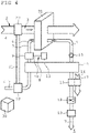
Fig. 4 eine schematische Darstellung einer wiederum abweichend ausgestalteten erfindungsgemäßen Wassergewinnungsvorrichtung. -
Fig. 1 zeigt eine schematische Darstellung einer erfindungsgemäßen Wassergewinnungsvorrichtung 1. Die Wassergewinnungsvorrichtung 1 weist ein erstes Durchführungsrohr 2 auf, das einen Eingangsluftstrom 3 führt, der durch einen Pfeil symbolisiert wird. Der Eingangsluftstrom 3 speist sich aus Umgebungsluft 4, die die Wassergewinnungsvorrichtung 1 umgibt. Der Eingangsluftstrom 3 könnte abweichend von dem dargestellten Ausführungsbeispiel auch beispielsweise aus der Abluft oder Fortluft einer Lüftungsanlage oder Luftkonditionierungsanlage gespeist werden. - Der Eingangsluftstrom 3 wird innerhalb der Wassergewinnungsvorrichtung 1 durch einen Abschnitt eines Sorptionsrad 5 hindurchgeführt. Der Eingangsluftstrom 3 durchströmt das Sorptionsrad 5, wobei eine Adsorption von Wasser aus dem Eingangsluftstrom 3 an nicht dargestellten Strukturen innerhalb des Sorptionsrads 5 stattfindet. Das Sorptionsrad 5 ist drehbar gelagert und wird durch einen Motor angetrieben. Das Sorptionsrad 5 befindet sich beim Betrieb der Wassergewinnungsvorrichtung 1 in Rotation, sodass der mit adsorbiertem Wasser beladene Abschnitt des Sorptionsrads 5 weitergedreht wird und neue Abschnitte des Sorptionsrads 5 von dem Eingangsluftstrom 3 durchströmt und mit Wasser beladen werden. An Stelle des Sorptionsrads 5 kann auch eine abweichend ausgebildete Absorptionseinrichtung oder allgemein eine Sorptionseinrichtung verwendet werden.
- Die Wassergewinnungsvorrichtung 1 weist einen zweiten Führungskanal 6 auf, der einen Feuchtluftstrom 7 führt, der ebenfalls durch einen Pfeil symbolisiert wird. Der Feuchtluftstrom 7 durchströmt ebenfalls das Sorptionsrad 5, wobei der Eingangsluftstrom 3 und der Feuchtluftstrom 7 getrennt voneinander durch das Sorptionsrad 5 geführt werden. Der Feuchtluftstrom 7 wird dabei derart durch das Sorptionsrad 5 geführt, dass der von dem Eingangsluftstrom 3 bereits durchströmte und mit Wasser beladene Abschnitt des Sorptionsrads 5 das adsorbierte Wasser möglichst vollständig an den dann durchströmenden Feuchtluftstrom 7 wieder abgibt.
- Der Feuchtluftstrom 7 wird durch eine Wärmezufuhreinrichtung 8 erwärmt, bevor er das Sorptionsrad 5 durchströmt. Die Wärmezufuhreinrichtung 8 wird durch ein Wärmeübertragungselement 9 und ein Wärmeleitelement 10 gebildet. Das Wärmeleitelement 10 ist mit einer externen Wärmequelle 11 wärmeleitfähig verbunden. Der Feuchtluftstrom 7 durchströmt vor dessen Zuführung zu dem Sorptionsrad 5 das Wärmeübertragungselement 9 und kann somit Wärme aus dem Wärmeübertragungselement 9 aufnehmen. Der erwärmte Feuchtluftstrom 7 durchströmt das Sorptionsrad 5 und nimmt über einen Desorptionsvorgang Wasser aus dem Sorptionsrad 5 auf.
- Die Wassergewinnungsvorrichtung 1 weist eine erste Kondensationsstufe 12 auf, die einen nicht näher dargestellten Kondensator enthält. Mittels der ersten Kondensationsstufe 12 kann Wasser aus dem Feuchtluftstrom 7 gewonnen werden.
- Zwischen der ersten Kondensationsstufe 12 und dem Sorptionsrad 5 ist ein Kompressor 13 angeordnet. Der Kompressor 13 dient dazu, den Feuchtluftstrom 7 zu verdichten. Durch die Verdichtung des Feuchtluftstroms 7 erniedrigt sich die Taupunkttemperatur des mit Wasser beladenen Feuchtluftstroms. Somit kann aus dem Feuchtluftstrom 7 in der nachfolgenden ersten Kondensationsstufe 12 effizient Wasser abgeschieden werden.
- Die erste Kondensationsstufe 12 ist wärmeübertragend mit einem Erwärmungsabschnitt 14 des Feuchtluftstroms 7 verbunden, der vor dem Wärmeübertragungselement 9 angeordnet ist. Somit kann der Feuchtluftstrom 7 zusätzlich erwärmt werden, bevor er das Wärmeübertragungselement 9 durchströmt.
- Der zweite Führungskanal 6 führt den Feuchtluftstrom 7 nach der ersten Kondensationsstufe 12 einer nachfolgend angeordneten zweiten Kondensationsstufe 15 zu. Der zweiten Kondensationsstufe 15 wird zusätzlich ein Kühlfluidstrom 16 durch einen Kühlkanal 17 zugeführt. Der Kühlfluidstrom 16 kühlt die zweite Kondensationsstufe 15, sodass ein Kondensationsvorgang an der zweiten Kondensationsstufe 15 verbessert wird.
- Der zweiten Kondensationsstufe 15 schließen sich eine Expansionsmaschine 18 und eine dritte Kondensationsstufe 19 an. Durch die Expansionsmaschine 18 wird der Feuchtluftstrom 7 entspannt. Hierdurch kühlt der Feuchtluftstrom 7 ab, wodurch ein Kondensationsvorgang in der dritten Kondensationsstufe 19 verbessert wird.
- Der Feuchtluftstrom 7 wird durch den zweiten Führungskanal 6 nach Durchströmung der dritten Kondensationsstufe 19 einem Wärmeabgabeelement 20 einer Wärmeübertragungseinrichtung zugeführt. Das Wärmeabgabeelement 20 ist über eine Wärmetransfereinrichtung 21 mit einem Wärmeaufnahmeelement 22 verbunden, das von dem Eingangsluftstrom 3 durchströmt wird. Dem einströmenden Eingangsluftstrom 3 wird von dem Wärmeaufnahmeelement 22 der Wärmeübertragungseinrichtung Wärme entzogen und der Eingangsluftstrom 3 dadurch abgekühlt, während dem Feuchtluftstrom 7 durch das Wärmeabgabeelement 20 Wärme zugeführt wird und der Feuchtluftstrom 7 dadurch erwärmt wird. Durch die Kühlung des Eingangsluftstroms 3 wird die Adsorption von Wasser durch das Sorptionsrad 5 aus dem Eingangsluftstrom 3 verbessert. Die dabei dem Eingangsluftstrom 3 entzogene Wärmeenergie wird durch die Wärmeübertragungseinrichtung zur Erwärmung des Feuchtluftstroms 7 vor der erneuten Durchführung durch das Sorptionsrad 5 genutzt.
- Der zweite Führungskanal 6 führt den Feuchtluftstrom 7 innerhalb der Wassergewinnungsvorrichtung 1 in einem geschlossenen Kreislauf.
-
Fig. 2 zeigt ein schematisches Ablaufdiagramm eines Verfahrens zur Wassergewinnung gemäß der vorliegenden Erfindung. Dabei wird in einem Sorptionsschritt 23 Wasser aus einem Eingangsluftstrom 3 sorbiert. Dies kann erfindungsgemäß mittels eines Sorptionsrads 5 erfolgen. In einem Erwärmungsschritt 24 wird ein Feuchtluftstrom 7 erwärmt, wozu dem Feuchtluftstrom 7 erfindungsgemäß Wärme aus einer externen Wärmequelle 11 zugeführt werden kann. Daraufhin wird das sorbierte Wasser an den erwärmten Feuchtluftstrom 7 in einem Abgabeschritt 25 abgegeben. Anschließend wird der Feuchtluftstrom 7 in einem Verdichtungsschritt 26 verdichtet. Dies kann erfindungsgemäß mittels eines Kompressors 13 erfolgen. Schließlich wird in einem ersten Kondensationsschritt 27 Wasser aus dem Feuchtluftstrom 7 gewonnen. Erfindungsgemäß kann dies mittels eines Kondensators erfolgen. Nach dem ersten Kondensationsschritt 27 können gegebenenfalls zusätzlich zweite und dritte bzw. weitere Kondensationsschritte 27', 27" nacheinander durchlaufen werden. - In
Fig. 3 ist exemplarisch eine abweichende Ausgestaltung der inFig. 1 dargestellten erfindungsgemäßen Wassergewinnungsvorrichtung 1 gezeigt. Auf die übereinstimmend ausgestalteten Merkmale wird dabei nachfolgend nicht näher eingegangen. Der Eingangsluftstrom 3 wird durch eine Kühleinrichtung 28 abgekühlt, die nicht mit weiteren Komponenten der Wassergewinnungsvorrichtung 1 in Verbindung steht. Der Kompressor 13 und die Expansionsmaschine 18 sind über eine gemeinsame Welle 29 miteinander verbunden, so dass ein energieeffizienter Betrieb des Kompressors und der Expansionsmaschine 18 ermöglicht wird. Es wäre ebenfalls möglich, den Kompressor 13 und die Expansionsmaschine 18 nicht durch eine mechanische Wirkverbindung miteinander zu verbinden, sondern eine ausschließlich energieübertragende Verbindung vorzusehen. - In
Fig. 4 ist exemplarisch eine wiederum abweichende Ausgestaltung einer erfindungsgemäßen Wassergewinnungsvorrichtung 1 gezeigt. Der Feuchtluftstrom 7 wird dabei im Gegensatz zu den inFig. 1 undFig. 3 gezeigten Ausführungsbeispielen nicht in einem geschlossenen Kreislauf geführt, sondern aus der Umgebungsluft 4 angesaugt. Der Feuchtluftstrom 7 könnte auch aus einem Feuchtluftreservoir 30 angesaugt werden, in welchem vorkonditionierte Feuchtluft gesammelt und bevorratet wird. Der angesaugte Feuchtluftstrom 7 wird zunächst dem Wärmeabgabeelement 20 der Wärmeübertragungseinrichtung zugeführt. Dem einströmenden Eingangsluftstrom 3 wird von dem Wärmeaufnahmeelement 22 der Wärmeübertragungseinrichtung Wärme entzogen und der Eingangsluftstrom 3 dadurch abgekühlt, während dem Feuchtluftstrom 7 durch das Wärmeabgabeelement 20 Wärme zugeführt wird, sodass der angesaugte Feuchtluftstrom 7 erwärmt wird. Anschließend wird der Feuchtluftstrom 7 in dem Erwärmungsabschnitt 14 von der ersten Kondensationsstufe 14 erwärmt, und nachfolgend noch von der Wärmezufuhreinrichtung 8 erwärmt, die von dem Wärmeübertragungselement 9 und dem Wärmeleitelement 10 gebildet wird, das mit der externen Wärmequelle 11 wärmeleitfähig verbunden ist. - Der derart vorgewärmte Feuchtluftstrom 7 wird ebenso wie der aus der Umgebungsluft 4 angesaugte Eingangsluftstrom 3 durch das Sorptionselement geführt, welches als Rieselsorptionsanlage 31 ausgebildet ist. In der Rieselsorptionsanlage 31 rieselt eine Absorptionsflüssigkeit an einer Rieselstruktur herab. Der an der Rieselstruktur vorbeiströmende Eingangsluftstrom 3 gibt Wasser an die Absorptionsflüssigkeit ab. Der Feuchtluftstrom 7 durchströmt die Rieselsorptionsanlage 31 und nimmt an der herabrieselnden Absorptionsflüssigkeit absorbiertes Wasser auf.
- Anschließend wird der Feuchtluftstrom 7 in dem Kompressor 13 verdichtet, um dann in der ersten Kondensationsstufe 12 Wasser aus dem Feuchtluftstrom 7 zu entziehen. In der zweiten Kondensationsstufe 15, die durch den Kühlfluidstrom 16 gekühlt wird, wird ebenfalls Wasser dem Feuchtluftstrom 7 entzogen. Nach einer Expansion des Feuchtluftstroms 7 in der Expansionsmaschine 18 wird in einer dritten Kondensationsstufe 19 erneut Wasser entzogen. Der Feuchtluftstrom 7 wird in den Kondensationsstufen 12, 15 und 19 sukzessive entfeuchtet und abgekühlt. Der in der dritten Kondensationsstufe 19 entfeuchtete Feuchtluftstrom 7 wird in die Umgebungsluft 4 abgeführt.
-
- 1. Wassergewinnungsvorrichtung
- 2. Erster Führungskanal
- 3. Eingangsluftstrom
- 4. Umgebungsluft
- 5. Sorptionsrad
- 6. Zweiter Führungskanal
- 7. Feuchtluftstrom
- 8. Wärmezufuhreinrichtung
- 9. Wärmeabgabeelement
- 10. Wärmeleitelement
- 11. Externe Wärmequelle
- 12. Erste Kondensationsstufe
- 13. Kompressor
- 14. Erwärmungsabschnitt
- 15. Zweite Kondensationsstufe
- 16. Kühlfluidstrom
- 17. Kühlkanal
- 18. Expansionsmaschine
- 19. Dritte Kondensationsstufe
- 20. Wärmeabgabeelement
- 21. Wärmetransfereinrichtung
- 22. Wärmeaufnahmeelement
- 23. Sorptionsschritt
- 24. Erwärmungsschritt
- 25. Abgabeschritt
- 26. Verdichtungsschritt
- 27. Erster Kondensationsschritt
- 27'. Zweiter Kondensationsschritt
- 27". Dritter Kondensationsschritt
- 28. Kühleinrichtung
- 29. Welle
- 30. Feuchtluftreservoir
- 31. Rieselsorptionsanlage
Claims (16)
- Wassergewinnungsvorrichtung (1) zur Gewinnung von Wasser aus einem Eingangsluftstrom (3),- mit einem Sorptionselement zur Sorption von Wasser aus dem Eingangsluftstrom (3) und zur Abgabe von Wasser an einen durch die Wassergewinnungsvorrichtung (1) geführten Feuchtluftstrom (7), wobei das Sorptionselement so angeordnet ist, dass es von dem Eingangsluftstrom (3) und den Feuchtluftstrom (7) durchströmt werden kann,- mit einer Wärmezufuhreinrichtung (8) zur Erwärmung des Feuchtluftstroms (7), bevor dieser das Sorptionselement durchströmt, sodass die Abgabe von Wasser an den Feuchtluftstrom (7) verbessert wird, und- mit einer ersten Kondensationsstufe (12), die einen Kondensator zur Gewinnung von Wasser aus dem Feuchtluftstrom (7) aufweist,dadurch gekennzeichnet, dass die Wassergewinnungsvorrichtung (1) einen Kompressor (13) zur Verdichtung des Feuchtluftstroms (7) aufweist, der zwischen dem Sorptionselement und der ersten Kondensationsstufe (12) angeordnet ist und die absolute Feuchtigkeit des verdichteten Feuchtluftstroms (7) erhöht, wobei der Kompressor (13) zwischen einer Ansaugseite und einer Druckseite des Kompressors (13) ein als Druckverhältnis bezeichneten Quotienten von Enddruck durch Saugdruck von mehr als 1,3 erzielt, dass die Wassergewinnungsvorrichtung (1) eine zweite Kondensationsstufe (15) mit einem Kondensator aufweist, wobei die zweite Kondensationsstufe (15) so angeordnet ist, dass der Feuchtluftstrom (7) sie in Strömungsrichtung nach der ersten Kondensationsstufe (12) durchströmt, und dass die Wassergewinnungsvorrichtung (1) eine Expansionsmaschine (18) aufweist, die so angeordnet ist, dass der Feuchtluftstrom (7) die Expansionsmaschine (18) nach der zweiten Kondensationsstufe (15) durchläuft.
- Wassergewinnungsvorrichtung (1) nach Anspruch 1, dadurch gekennzeichnet, dass der Kompressor (13) ein Druckverhältnis von mehr als 3, vorzugsweise von mehr als 5 erzielt.
- Wassergewinnungsvorrichtung (1) nach einem der vorhergehenden Ansprüche, dadurch gekennzeichnet, dass der Feuchtluftstrom (7) durch die Wassergewinnungsvorrichtung (1) in einem geschlossenen Kreislauf geführt wird.
- Wassergewinnungsvorrichtung (1) nach einem der vorhergehenden Ansprüche, dadurch gekennzeichnet, dass die erste Kondensationsstufe (12) mit einem Erwärmungsabschnitt (14) des Feuchtluftstroms (7) vor der Wärmezufuhreinrichtung (8) in wärmeleitfähiger Verbindung steht, wobei der Erwärmungsabschnitt (14) des Feuchtluftstroms (7) der Wärmezufuhreinrichtung (8) in Strömungsrichtung vorangeht, sodass bei einer Kondensation in der ersten Kondensationsstufe (12) entstehende Wärme zur Erwärmung des Feuchtluftstroms (7) nutzbar wird.
- Wassergewinnungsvorrichtung (1) nach einem der vorhergehenden Ansprüche, dadurch gekennzeichnet, dass die zweite Kondensationsstufe (15) eine Durchführung für einen Kühlfluidstrom (16) zur Kühlung der Zweiten Kondensationsstufe (15) aufweist, um einen Kondensationsvorgang in der zweiten Kondensationsstufe (15) zu unterstützen.
- Wassergewinnungsvorrichtung (1) nach einem der vorhergehenden Ansprüche, dadurch gekennzeichnet, dass die Wassergewinnungsvorrichtung (1) eine dritte Kondensationsstufe (19) mit einem Kondensator aufweist, wobei die dritte Kondensationsstufe (19) so angeordnet ist, dass der Feuchtluftstrom (7) sie nach der Expansionsmaschine (18) durchströmt.
- Wassergewinnungsvorrichtung (1) nach einem der vorhergehenden Ansprüche, dadurch gekennzeichnet, dass die Wassergewinnungsvorrichtung (1) ein Wärmeabgabeelement (20) aufweist, das so angeordnet ist, dass der Feuchtluftstrom (7) mit dem Wärmeabgabeelement (20) erwärmt werden kann, nachdem der Feuchtluftstrom (7) mindestens eine Kondensationsstufe durchlaufen hat.
- Wassergewinnungsvorrichtung (1) nach Anspruch 7, dadurch gekennzeichnet, dass das Wärmeabgabeelement (20) mit einem an dem Eingangsluftstrom (3) in Strömungsrichtung vor dem Sorptionselement angeordneten Wärmeaufnahmeelement (22) wärmeleitfähig verbunden ist, das so angeordnet ist, dass der Eingangsluftstrom (3) mit dem Wärmeaufnahmeelement (22) gekühlt und der Feuchtluftstrom (7) mit dem Wärmeabgabeelement (20) erwärmt wird.
- Wassergewinnungsvorrichtung (1) nach einem der vorhergehenden Ansprüche, dadurch gekennzeichnet, dass der Kompressor (13) und die Expansionsmaschine (18) miteinander in Wirkverbindung stehen, sodass die bei einer Expansion des verdichteten Feuchtluftstroms (7) nutzbar werdende Expansionsenergie energieeffizient zur Verdichtung des Feuchtluftstroms (7) mit dem Kompressor (13) genutzt werden kann.
- Verfahren zur Wassergewinnung aus einem Eingangsluftstrom (3),- wobei Wasser aus dem Eingangsluftstrom (3) in einem Sorptionsschritt (23) sorbiert wird,- wobei das Wasser anschließend an einen Feuchtluftstrom (7) abgegeben wird,- wobei der Feuchtluftstrom (7) in einem Erwärmungsschritt (24) vor Abgabe des Wassers an den Feuchtluftstrom (7) erwärmt wird, sodass die Abgabe von Wasser an den Feuchtluftstrom (7) verbessert wird, und- wobei in einem ersten Kondensationsschritt (27) Wasser aus dem Feuchtluftstrom (7) gewonnen wird, dadurch gekennzeichnet, dass der Feuchtluftstrom (7) nach Abgabe des Wassers an den Feuchtluftstrom (7) und vor dem ersten Kondensationsschritt (27) mit einem Kompressor (13) verdichtet wird, wobei der Feuchtluftstrom (7) mit dem Kompressor (13) mehr als 1,3-fach verdichtet wird, aus dem Feuchtluftstrom (7) nach dem ersten Kondensationsschritt (27) in einem zweiten Kondensationsschritt (27') Wasser gewonnen wird, und dass der Feuchtluftstrom (7) nach dem zweiten Kondensationsschritt (27') entspannt wird.
- Verfahren nach Anspruch 10, dadurch gekennzeichnet, dass der Feuchtluftstrom (7) in einem geschlossenen Kreislauf geführt wird.
- Verfahren nach einem der Ansprüche 10 oder 11, dadurch gekennzeichnet, dass bei dem ersten Kondensationsschritt (27) anfallende Wärme dem Feuchtluftstrom (7) zugeführt wird, unmittelbar bevor der Feuchtluftstrom (7) bei dem Erwärmungsschritt (24) erwärmt wird, sodass bei dem ersten Kondensationsschritt (27) anfallende Wärme zur Erwärmung des Feuchtluftstroms (7) genutzt wird.
- Verfahren nach einem der Ansprüche 10 bis 12, dadurch gekennzeichnet, dass bei dem zweiten Kondensationsschritt (27') einem dem zweiten Kondensationsschritt (27') zugeordneten Kondensator ein Kühlfluidstrom (16) zugeführt wird, um einen Kondensationsvorgang bei dem zweiten Kondensationsschritt (27') zu unterstützen.
- Verfahren nach einem der Ansprüche 10 bis 13, dadurch gekennzeichnet, dass aus dem Feuchtluftstrom (7) nach der Entspannung in einem dritten Kondensationsschritt (27") Wasser gewonnen wird.
- Verfahren nach einem der Ansprüche 10 bis 14, dadurch gekennzeichnet, dass Wärme von dem Eingangsluftstrom (3) in den Feuchtluftstrom (7) überführt wird, nachdem der Feuchtluftstrom (7) mindestens einem Kondensationsschritt unterworfen gewesen ist, sodass der Eingangsluftstrom (3) gekühlt und der Feuchtluftstrom (7) erwärmt wird.
- Verfahren nach einem der Ansprüche 10 bis 15, dadurch gekennzeichnet, dass der Feuchtluftstrom (7) nach dem zweiten Kondensationsschritt (27') oder gegebenenfalls n1ch dem dritten Kondensationsschritt (27") abgeführt und ein neuer Feuchtluftstrom (7) aus dem Eingangsluftstrom (3) oder aus einem Feuchtluftstromreservoir (30) angesaugt wird.
Applications Claiming Priority (2)
| Application Number | Priority Date | Filing Date | Title |
|---|---|---|---|
| DE102017108170.4A DE102017108170A1 (de) | 2017-04-18 | 2017-04-18 | Wassergewinnungsvorrichtung und Verfahren zur Wassergewinnung |
| PCT/EP2018/059731 WO2018192905A2 (de) | 2017-04-18 | 2018-04-17 | Wassergewinnungsvorrichtung und verfahren zur wassergewinnung |
Publications (2)
| Publication Number | Publication Date |
|---|---|
| EP3612290A2 EP3612290A2 (de) | 2020-02-26 |
| EP3612290B1 true EP3612290B1 (de) | 2022-08-10 |
Family
ID=62186389
Family Applications (1)
| Application Number | Title | Priority Date | Filing Date |
|---|---|---|---|
| EP18725110.3A Active EP3612290B1 (de) | 2017-04-18 | 2018-04-17 | Wassergewinnungsvorrichtung und verfahren zur wassergewinnung |
Country Status (3)
| Country | Link |
|---|---|
| EP (1) | EP3612290B1 (de) |
| DE (1) | DE102017108170A1 (de) |
| WO (1) | WO2018192905A2 (de) |
Families Citing this family (6)
| Publication number | Priority date | Publication date | Assignee | Title |
|---|---|---|---|---|
| CN109224496B (zh) * | 2018-10-30 | 2021-04-09 | 临安派祺空气净化科技有限公司 | 一种压缩空气造水过滤装置 |
| TWI668397B (zh) * | 2018-11-23 | 2019-08-11 | 致茂電子股份有限公司 | 冷凝系統 |
| CN109372060B (zh) * | 2018-12-13 | 2020-12-22 | 临安派祺空气净化科技有限公司 | 一种便携式压缩空气造水装置 |
| US11602712B2 (en) | 2020-03-11 | 2023-03-14 | Honeywell International Inc. | Atmospheric water extraction system |
| BE1028400B1 (nl) * | 2020-06-16 | 2022-01-25 | Atlas Copco Airpower Nv | Inrichting en werkwijze voor het onttrekken van water uit vochtige omgevingslucht |
| DE102022125636A1 (de) * | 2022-10-05 | 2024-04-11 | Grohe Ag | Vorrichtung zur Bereitstellung von Trinkwasser |
Family Cites Families (10)
| Publication number | Priority date | Publication date | Assignee | Title |
|---|---|---|---|---|
| GB2237373B (en) * | 1989-10-10 | 1993-12-08 | Aisin Seiki | Air cycle air conditioner for heating and cooling |
| JP4066553B2 (ja) * | 1999-03-17 | 2008-03-26 | ダイキン工業株式会社 | 空気調和装置 |
| JP4703889B2 (ja) * | 2000-06-05 | 2011-06-15 | 富士フイルム株式会社 | 乾式除湿機再生気体の循環濃縮処理方法 |
| DE10201427A1 (de) * | 2002-01-16 | 2003-07-24 | Liebherr Aerospace Gmbh | System zur Luftentfeuchtung in Klimaanlagen |
| US6990829B2 (en) * | 2003-08-29 | 2006-01-31 | Visteon Global Technologies, Inc. | Air cycle HVAC system having secondary air stream |
| US7101414B2 (en) * | 2004-04-27 | 2006-09-05 | Munters Corporation | Rotary bed sorption system including at least one recycled isolation loop, and methods of designing and operating such a system |
| KR100707448B1 (ko) * | 2005-03-22 | 2007-04-13 | 엘지전자 주식회사 | 공기조화기 |
| US7251945B2 (en) | 2005-06-06 | 2007-08-07 | Hamilton Sandstrand Corporation | Water-from-air system using desiccant wheel and exhaust |
| US20070028769A1 (en) * | 2005-08-05 | 2007-02-08 | Eplee Dustin M | Method and apparatus for producing potable water from air including severely arid and hot climates |
| US9574782B2 (en) * | 2012-01-20 | 2017-02-21 | Innovent Air Handling Equipment, LLC | Dehumidification system |
-
2017
- 2017-04-18 DE DE102017108170.4A patent/DE102017108170A1/de not_active Withdrawn
-
2018
- 2018-04-17 EP EP18725110.3A patent/EP3612290B1/de active Active
- 2018-04-17 WO PCT/EP2018/059731 patent/WO2018192905A2/de not_active Ceased
Also Published As
| Publication number | Publication date |
|---|---|
| WO2018192905A2 (de) | 2018-10-25 |
| EP3612290A2 (de) | 2020-02-26 |
| DE102017108170A1 (de) | 2018-10-18 |
| WO2018192905A3 (de) | 2019-03-21 |
Similar Documents
| Publication | Publication Date | Title |
|---|---|---|
| WO2018192905A2 (de) | Wassergewinnungsvorrichtung und verfahren zur wassergewinnung | |
| EP1329381B1 (de) | Flugzeugklimaanlage | |
| DE69821134T2 (de) | Zweiwellenklimaanlage | |
| DE2519371C2 (de) | Vorrichtung zum Kühlen für Klimatisierungszwecke | |
| CH699192A1 (de) | Verfahren und Vorrichtung für die Aufbereitung der einem Raum zuzuführenden Luft auf eine gewünschte Temperatur und eine gewünschte Feuchtigkeit. | |
| WO2007131627A1 (de) | Trocknung von druckluft unter nutzung der verdichterwärme mit geschlossenem regenerationskreislauf | |
| DE102017124811A1 (de) | Klimatisierungssystem zum Konditionieren der Luft eines Fahrgastraums eines Kraftfahrzeugs und Verfahren zum Betreiben des Klimatisierungssystems | |
| WO2025021927A1 (de) | Kombination rotierbare vortrocknungseinheit mit co2-gewinnung | |
| DE112015000750T5 (de) | Kältefluidkreislauf zur thermischen Behandlung eines Kraftfahrzeugs | |
| DE633985C (de) | Verfahren und Vorrichtung zur Kuehlung von Raeumen, insbesondere von Eisenbahnfahrzeugen | |
| DE102008048016A1 (de) | Fahrzeugklimaanlage | |
| DE102016223528B4 (de) | Kabinenabluftunterstützt betreibbare Flugzeugklimaanlage mit einem elektrisch angetriebenen Umgebungsluftkompressor | |
| EP3639906A1 (de) | Verfahren zum gewinnen von wasser und wassergewinnungsvorrichtung | |
| DE102004050182B4 (de) | Verfahren zur Luftkonditionierung | |
| DE10159148A1 (de) | Klimaanlage | |
| EP4056940A1 (de) | Vorrichtung und verfahren zum trocknen von gegenständen und/oder materialien, insbesondere holz | |
| DE102020213544B4 (de) | Gaskältemaschine, Verfahren zum Betreiben einer Gaskältemaschine und Verfahren zum Herstellen einer Gaskältemaschine mit einem Rekuperator um den Ansaugbereich | |
| DE102012017314B4 (de) | System zur Wirkungsgradsteigerung von zwei- oder mehrstufigen Verdichteranordnungen | |
| DE2050898A1 (de) | Anlage zum Heizen und Kühlen von Kraftfahrzeug-Innenräumen | |
| DE2801258A1 (de) | Raum-klimaanlage | |
| DE202017105468U1 (de) | Wärmetauschvorrichtung | |
| DE4303219A1 (de) | Kaltluft-Kältemaschinen-Anlage | |
| DE10338418B4 (de) | Verfahren und Anlage zur Abgasreinigung | |
| DE102016106046A1 (de) | DEC-Klimaanlage zur Klimatisierung eines Raums und Verfahren zur Klimatisierung eines Raums | |
| DE102018132274A1 (de) | Verfahren und Vorrichtung zur Optimierung der Druckgaserzeugung |
Legal Events
| Date | Code | Title | Description |
|---|---|---|---|
| STAA | Information on the status of an ep patent application or granted ep patent |
Free format text: STATUS: UNKNOWN |
|
| STAA | Information on the status of an ep patent application or granted ep patent |
Free format text: STATUS: THE INTERNATIONAL PUBLICATION HAS BEEN MADE |
|
| PUAI | Public reference made under article 153(3) epc to a published international application that has entered the european phase |
Free format text: ORIGINAL CODE: 0009012 |
|
| STAA | Information on the status of an ep patent application or granted ep patent |
Free format text: STATUS: REQUEST FOR EXAMINATION WAS MADE |
|
| 17P | Request for examination filed |
Effective date: 20191016 |
|
| AK | Designated contracting states |
Kind code of ref document: A2 Designated state(s): AL AT BE BG CH CY CZ DE DK EE ES FI FR GB GR HR HU IE IS IT LI LT LU LV MC MK MT NL NO PL PT RO RS SE SI SK SM TR |
|
| AX | Request for extension of the european patent |
Extension state: BA ME |
|
| DAV | Request for validation of the european patent (deleted) | ||
| DAX | Request for extension of the european patent (deleted) | ||
| GRAP | Despatch of communication of intention to grant a patent |
Free format text: ORIGINAL CODE: EPIDOSNIGR1 |
|
| STAA | Information on the status of an ep patent application or granted ep patent |
Free format text: STATUS: GRANT OF PATENT IS INTENDED |
|
| INTG | Intention to grant announced |
Effective date: 20220330 |
|
| GRAS | Grant fee paid |
Free format text: ORIGINAL CODE: EPIDOSNIGR3 |
|
| GRAA | (expected) grant |
Free format text: ORIGINAL CODE: 0009210 |
|
| STAA | Information on the status of an ep patent application or granted ep patent |
Free format text: STATUS: THE PATENT HAS BEEN GRANTED |
|
| AK | Designated contracting states |
Kind code of ref document: B1 Designated state(s): AL AT BE BG CH CY CZ DE DK EE ES FI FR GB GR HR HU IE IS IT LI LT LU LV MC MK MT NL NO PL PT RO RS SE SI SK SM TR |
|
| REG | Reference to a national code |
Ref country code: AT Ref legal event code: REF Ref document number: 1510067 Country of ref document: AT Kind code of ref document: T Effective date: 20220815 Ref country code: CH Ref legal event code: EP |
|
| REG | Reference to a national code |
Ref country code: IE Ref legal event code: FG4D Free format text: LANGUAGE OF EP DOCUMENT: GERMAN |
|
| REG | Reference to a national code |
Ref country code: DE Ref legal event code: R096 Ref document number: 502018010357 Country of ref document: DE |
|
| REG | Reference to a national code |
Ref country code: DE Ref legal event code: R082 Ref document number: 502018010357 Country of ref document: DE Representative=s name: HABERMANN INTELLECTUAL PROPERTY PARTNERSCHAFT , DE |
|
| REG | Reference to a national code |
Ref country code: NL Ref legal event code: MP Effective date: 20220810 |
|
| REG | Reference to a national code |
Ref country code: LT Ref legal event code: MG9D |
|
| PG25 | Lapsed in a contracting state [announced via postgrant information from national office to epo] |
Ref country code: SE Free format text: LAPSE BECAUSE OF FAILURE TO SUBMIT A TRANSLATION OF THE DESCRIPTION OR TO PAY THE FEE WITHIN THE PRESCRIBED TIME-LIMIT Effective date: 20220810 Ref country code: RS Free format text: LAPSE BECAUSE OF FAILURE TO SUBMIT A TRANSLATION OF THE DESCRIPTION OR TO PAY THE FEE WITHIN THE PRESCRIBED TIME-LIMIT Effective date: 20220810 Ref country code: PT Free format text: LAPSE BECAUSE OF FAILURE TO SUBMIT A TRANSLATION OF THE DESCRIPTION OR TO PAY THE FEE WITHIN THE PRESCRIBED TIME-LIMIT Effective date: 20221212 Ref country code: NO Free format text: LAPSE BECAUSE OF FAILURE TO SUBMIT A TRANSLATION OF THE DESCRIPTION OR TO PAY THE FEE WITHIN THE PRESCRIBED TIME-LIMIT Effective date: 20221110 Ref country code: NL Free format text: LAPSE BECAUSE OF FAILURE TO SUBMIT A TRANSLATION OF THE DESCRIPTION OR TO PAY THE FEE WITHIN THE PRESCRIBED TIME-LIMIT Effective date: 20220810 Ref country code: LV Free format text: LAPSE BECAUSE OF FAILURE TO SUBMIT A TRANSLATION OF THE DESCRIPTION OR TO PAY THE FEE WITHIN THE PRESCRIBED TIME-LIMIT Effective date: 20220810 Ref country code: LT Free format text: LAPSE BECAUSE OF FAILURE TO SUBMIT A TRANSLATION OF THE DESCRIPTION OR TO PAY THE FEE WITHIN THE PRESCRIBED TIME-LIMIT Effective date: 20220810 Ref country code: FI Free format text: LAPSE BECAUSE OF FAILURE TO SUBMIT A TRANSLATION OF THE DESCRIPTION OR TO PAY THE FEE WITHIN THE PRESCRIBED TIME-LIMIT Effective date: 20220810 |
|
| PG25 | Lapsed in a contracting state [announced via postgrant information from national office to epo] |
Ref country code: PL Free format text: LAPSE BECAUSE OF FAILURE TO SUBMIT A TRANSLATION OF THE DESCRIPTION OR TO PAY THE FEE WITHIN THE PRESCRIBED TIME-LIMIT Effective date: 20220810 Ref country code: IS Free format text: LAPSE BECAUSE OF FAILURE TO SUBMIT A TRANSLATION OF THE DESCRIPTION OR TO PAY THE FEE WITHIN THE PRESCRIBED TIME-LIMIT Effective date: 20221210 Ref country code: HR Free format text: LAPSE BECAUSE OF FAILURE TO SUBMIT A TRANSLATION OF THE DESCRIPTION OR TO PAY THE FEE WITHIN THE PRESCRIBED TIME-LIMIT Effective date: 20220810 Ref country code: GR Free format text: LAPSE BECAUSE OF FAILURE TO SUBMIT A TRANSLATION OF THE DESCRIPTION OR TO PAY THE FEE WITHIN THE PRESCRIBED TIME-LIMIT Effective date: 20221111 |
|
| PG25 | Lapsed in a contracting state [announced via postgrant information from national office to epo] |
Ref country code: SM Free format text: LAPSE BECAUSE OF FAILURE TO SUBMIT A TRANSLATION OF THE DESCRIPTION OR TO PAY THE FEE WITHIN THE PRESCRIBED TIME-LIMIT Effective date: 20220810 Ref country code: RO Free format text: LAPSE BECAUSE OF FAILURE TO SUBMIT A TRANSLATION OF THE DESCRIPTION OR TO PAY THE FEE WITHIN THE PRESCRIBED TIME-LIMIT Effective date: 20220810 Ref country code: ES Free format text: LAPSE BECAUSE OF FAILURE TO SUBMIT A TRANSLATION OF THE DESCRIPTION OR TO PAY THE FEE WITHIN THE PRESCRIBED TIME-LIMIT Effective date: 20220810 Ref country code: DK Free format text: LAPSE BECAUSE OF FAILURE TO SUBMIT A TRANSLATION OF THE DESCRIPTION OR TO PAY THE FEE WITHIN THE PRESCRIBED TIME-LIMIT Effective date: 20220810 Ref country code: CZ Free format text: LAPSE BECAUSE OF FAILURE TO SUBMIT A TRANSLATION OF THE DESCRIPTION OR TO PAY THE FEE WITHIN THE PRESCRIBED TIME-LIMIT Effective date: 20220810 |
|
| REG | Reference to a national code |
Ref country code: DE Ref legal event code: R097 Ref document number: 502018010357 Country of ref document: DE |
|
| PG25 | Lapsed in a contracting state [announced via postgrant information from national office to epo] |
Ref country code: SK Free format text: LAPSE BECAUSE OF FAILURE TO SUBMIT A TRANSLATION OF THE DESCRIPTION OR TO PAY THE FEE WITHIN THE PRESCRIBED TIME-LIMIT Effective date: 20220810 Ref country code: EE Free format text: LAPSE BECAUSE OF FAILURE TO SUBMIT A TRANSLATION OF THE DESCRIPTION OR TO PAY THE FEE WITHIN THE PRESCRIBED TIME-LIMIT Effective date: 20220810 |
|
| PLBE | No opposition filed within time limit |
Free format text: ORIGINAL CODE: 0009261 |
|
| STAA | Information on the status of an ep patent application or granted ep patent |
Free format text: STATUS: NO OPPOSITION FILED WITHIN TIME LIMIT |
|
| PG25 | Lapsed in a contracting state [announced via postgrant information from national office to epo] |
Ref country code: AL Free format text: LAPSE BECAUSE OF FAILURE TO SUBMIT A TRANSLATION OF THE DESCRIPTION OR TO PAY THE FEE WITHIN THE PRESCRIBED TIME-LIMIT Effective date: 20220810 |
|
| 26N | No opposition filed |
Effective date: 20230511 |
|
| PGFP | Annual fee paid to national office [announced via postgrant information from national office to epo] |
Ref country code: FR Payment date: 20230417 Year of fee payment: 6 |
|
| PG25 | Lapsed in a contracting state [announced via postgrant information from national office to epo] |
Ref country code: SI Free format text: LAPSE BECAUSE OF FAILURE TO SUBMIT A TRANSLATION OF THE DESCRIPTION OR TO PAY THE FEE WITHIN THE PRESCRIBED TIME-LIMIT Effective date: 20220810 |
|
| REG | Reference to a national code |
Ref country code: CH Ref legal event code: PL |
|
| GBPC | Gb: european patent ceased through non-payment of renewal fee |
Effective date: 20230417 |
|
| PG25 | Lapsed in a contracting state [announced via postgrant information from national office to epo] |
Ref country code: LU Free format text: LAPSE BECAUSE OF NON-PAYMENT OF DUE FEES Effective date: 20230417 |
|
| REG | Reference to a national code |
Ref country code: BE Ref legal event code: MM Effective date: 20230430 |
|
| PG25 | Lapsed in a contracting state [announced via postgrant information from national office to epo] |
Ref country code: MC Free format text: LAPSE BECAUSE OF FAILURE TO SUBMIT A TRANSLATION OF THE DESCRIPTION OR TO PAY THE FEE WITHIN THE PRESCRIBED TIME-LIMIT Effective date: 20220810 |
|
| PG25 | Lapsed in a contracting state [announced via postgrant information from national office to epo] |
Ref country code: GB Free format text: LAPSE BECAUSE OF NON-PAYMENT OF DUE FEES Effective date: 20230417 |
|
| PG25 | Lapsed in a contracting state [announced via postgrant information from national office to epo] |
Ref country code: MC Free format text: LAPSE BECAUSE OF FAILURE TO SUBMIT A TRANSLATION OF THE DESCRIPTION OR TO PAY THE FEE WITHIN THE PRESCRIBED TIME-LIMIT Effective date: 20220810 Ref country code: LI Free format text: LAPSE BECAUSE OF NON-PAYMENT OF DUE FEES Effective date: 20230430 Ref country code: GB Free format text: LAPSE BECAUSE OF NON-PAYMENT OF DUE FEES Effective date: 20230417 Ref country code: CH Free format text: LAPSE BECAUSE OF NON-PAYMENT OF DUE FEES Effective date: 20230430 |
|
| REG | Reference to a national code |
Ref country code: IE Ref legal event code: MM4A |
|
| PG25 | Lapsed in a contracting state [announced via postgrant information from national office to epo] |
Ref country code: BE Free format text: LAPSE BECAUSE OF NON-PAYMENT OF DUE FEES Effective date: 20230430 |
|
| PG25 | Lapsed in a contracting state [announced via postgrant information from national office to epo] |
Ref country code: IE Free format text: LAPSE BECAUSE OF NON-PAYMENT OF DUE FEES Effective date: 20230417 |
|
| PG25 | Lapsed in a contracting state [announced via postgrant information from national office to epo] |
Ref country code: IE Free format text: LAPSE BECAUSE OF NON-PAYMENT OF DUE FEES Effective date: 20230417 |
|
| PG25 | Lapsed in a contracting state [announced via postgrant information from national office to epo] |
Ref country code: IT Free format text: LAPSE BECAUSE OF FAILURE TO SUBMIT A TRANSLATION OF THE DESCRIPTION OR TO PAY THE FEE WITHIN THE PRESCRIBED TIME-LIMIT Effective date: 20220810 |
|
| REG | Reference to a national code |
Ref country code: AT Ref legal event code: MM01 Ref document number: 1510067 Country of ref document: AT Kind code of ref document: T Effective date: 20230417 |
|
| PG25 | Lapsed in a contracting state [announced via postgrant information from national office to epo] |
Ref country code: AT Free format text: LAPSE BECAUSE OF NON-PAYMENT OF DUE FEES Effective date: 20230417 |
|
| PG25 | Lapsed in a contracting state [announced via postgrant information from national office to epo] |
Ref country code: AT Free format text: LAPSE BECAUSE OF NON-PAYMENT OF DUE FEES Effective date: 20230417 |
|
| PG25 | Lapsed in a contracting state [announced via postgrant information from national office to epo] |
Ref country code: BG Free format text: LAPSE BECAUSE OF FAILURE TO SUBMIT A TRANSLATION OF THE DESCRIPTION OR TO PAY THE FEE WITHIN THE PRESCRIBED TIME-LIMIT Effective date: 20220810 |
|
| PG25 | Lapsed in a contracting state [announced via postgrant information from national office to epo] |
Ref country code: BG Free format text: LAPSE BECAUSE OF FAILURE TO SUBMIT A TRANSLATION OF THE DESCRIPTION OR TO PAY THE FEE WITHIN THE PRESCRIBED TIME-LIMIT Effective date: 20220810 |
|
| PG25 | Lapsed in a contracting state [announced via postgrant information from national office to epo] |
Ref country code: FR Free format text: LAPSE BECAUSE OF NON-PAYMENT OF DUE FEES Effective date: 20240430 |
|
| PG25 | Lapsed in a contracting state [announced via postgrant information from national office to epo] |
Ref country code: FR Free format text: LAPSE BECAUSE OF NON-PAYMENT OF DUE FEES Effective date: 20240430 |
|
| PGFP | Annual fee paid to national office [announced via postgrant information from national office to epo] |
Ref country code: DE Payment date: 20250422 Year of fee payment: 8 |
|
| PG25 | Lapsed in a contracting state [announced via postgrant information from national office to epo] |
Ref country code: CY Free format text: LAPSE BECAUSE OF FAILURE TO SUBMIT A TRANSLATION OF THE DESCRIPTION OR TO PAY THE FEE WITHIN THE PRESCRIBED TIME-LIMIT; INVALID AB INITIO Effective date: 20180417 |
|
| PG25 | Lapsed in a contracting state [announced via postgrant information from national office to epo] |
Ref country code: HU Free format text: LAPSE BECAUSE OF FAILURE TO SUBMIT A TRANSLATION OF THE DESCRIPTION OR TO PAY THE FEE WITHIN THE PRESCRIBED TIME-LIMIT; INVALID AB INITIO Effective date: 20180417 |
|
| PG25 | Lapsed in a contracting state [announced via postgrant information from national office to epo] |
Ref country code: TR Free format text: LAPSE BECAUSE OF FAILURE TO SUBMIT A TRANSLATION OF THE DESCRIPTION OR TO PAY THE FEE WITHIN THE PRESCRIBED TIME-LIMIT Effective date: 20220810 |