EP3611778B1 - Battery module and electricity storage unit - Google Patents
Battery module and electricity storage unit Download PDFInfo
- Publication number
- EP3611778B1 EP3611778B1 EP18784036.8A EP18784036A EP3611778B1 EP 3611778 B1 EP3611778 B1 EP 3611778B1 EP 18784036 A EP18784036 A EP 18784036A EP 3611778 B1 EP3611778 B1 EP 3611778B1
- Authority
- EP
- European Patent Office
- Prior art keywords
- module
- plate
- axis
- battery
- battery module
- Prior art date
- Legal status (The legal status is an assumption and is not a legal conclusion. Google has not performed a legal analysis and makes no representation as to the accuracy of the status listed.)
- Active
Links
Images





Classifications
-
- H—ELECTRICITY
- H01—ELECTRIC ELEMENTS
- H01M—PROCESSES OR MEANS, e.g. BATTERIES, FOR THE DIRECT CONVERSION OF CHEMICAL ENERGY INTO ELECTRICAL ENERGY
- H01M10/00—Secondary cells; Manufacture thereof
- H01M10/42—Methods or arrangements for servicing or maintenance of secondary cells or secondary half-cells
- H01M10/425—Structural combination with electronic components, e.g. electronic circuits integrated to the outside of the casing
-
- H—ELECTRICITY
- H01—ELECTRIC ELEMENTS
- H01M—PROCESSES OR MEANS, e.g. BATTERIES, FOR THE DIRECT CONVERSION OF CHEMICAL ENERGY INTO ELECTRICAL ENERGY
- H01M50/00—Constructional details or processes of manufacture of the non-active parts of electrochemical cells other than fuel cells, e.g. hybrid cells
- H01M50/20—Mountings; Secondary casings or frames; Racks, modules or packs; Suspension devices; Shock absorbers; Transport or carrying devices; Holders
-
- H—ELECTRICITY
- H01—ELECTRIC ELEMENTS
- H01M—PROCESSES OR MEANS, e.g. BATTERIES, FOR THE DIRECT CONVERSION OF CHEMICAL ENERGY INTO ELECTRICAL ENERGY
- H01M50/00—Constructional details or processes of manufacture of the non-active parts of electrochemical cells other than fuel cells, e.g. hybrid cells
- H01M50/50—Current conducting connections for cells or batteries
- H01M50/528—Fixed electrical connections, i.e. not intended for disconnection
-
- H—ELECTRICITY
- H01—ELECTRIC ELEMENTS
- H01M—PROCESSES OR MEANS, e.g. BATTERIES, FOR THE DIRECT CONVERSION OF CHEMICAL ENERGY INTO ELECTRICAL ENERGY
- H01M10/00—Secondary cells; Manufacture thereof
- H01M10/04—Construction or manufacture in general
- H01M10/0472—Vertically superposed cells with vertically disposed plates
-
- H—ELECTRICITY
- H01—ELECTRIC ELEMENTS
- H01M—PROCESSES OR MEANS, e.g. BATTERIES, FOR THE DIRECT CONVERSION OF CHEMICAL ENERGY INTO ELECTRICAL ENERGY
- H01M10/00—Secondary cells; Manufacture thereof
- H01M10/04—Construction or manufacture in general
- H01M10/0486—Frames for plates or membranes
-
- H—ELECTRICITY
- H01—ELECTRIC ELEMENTS
- H01M—PROCESSES OR MEANS, e.g. BATTERIES, FOR THE DIRECT CONVERSION OF CHEMICAL ENERGY INTO ELECTRICAL ENERGY
- H01M50/00—Constructional details or processes of manufacture of the non-active parts of electrochemical cells other than fuel cells, e.g. hybrid cells
- H01M50/20—Mountings; Secondary casings or frames; Racks, modules or packs; Suspension devices; Shock absorbers; Transport or carrying devices; Holders
- H01M50/204—Racks, modules or packs for multiple batteries or multiple cells
- H01M50/207—Racks, modules or packs for multiple batteries or multiple cells characterised by their shape
- H01M50/209—Racks, modules or packs for multiple batteries or multiple cells characterised by their shape adapted for prismatic or rectangular cells
-
- H—ELECTRICITY
- H01—ELECTRIC ELEMENTS
- H01M—PROCESSES OR MEANS, e.g. BATTERIES, FOR THE DIRECT CONVERSION OF CHEMICAL ENERGY INTO ELECTRICAL ENERGY
- H01M50/00—Constructional details or processes of manufacture of the non-active parts of electrochemical cells other than fuel cells, e.g. hybrid cells
- H01M50/20—Mountings; Secondary casings or frames; Racks, modules or packs; Suspension devices; Shock absorbers; Transport or carrying devices; Holders
- H01M50/204—Racks, modules or packs for multiple batteries or multiple cells
- H01M50/207—Racks, modules or packs for multiple batteries or multiple cells characterised by their shape
- H01M50/211—Racks, modules or packs for multiple batteries or multiple cells characterised by their shape adapted for pouch cells
-
- H—ELECTRICITY
- H01—ELECTRIC ELEMENTS
- H01M—PROCESSES OR MEANS, e.g. BATTERIES, FOR THE DIRECT CONVERSION OF CHEMICAL ENERGY INTO ELECTRICAL ENERGY
- H01M50/00—Constructional details or processes of manufacture of the non-active parts of electrochemical cells other than fuel cells, e.g. hybrid cells
- H01M50/50—Current conducting connections for cells or batteries
- H01M50/543—Terminals
- H01M50/547—Terminals characterised by the disposition of the terminals on the cells
- H01M50/548—Terminals characterised by the disposition of the terminals on the cells on opposite sides of the cell
-
- H—ELECTRICITY
- H01—ELECTRIC ELEMENTS
- H01M—PROCESSES OR MEANS, e.g. BATTERIES, FOR THE DIRECT CONVERSION OF CHEMICAL ENERGY INTO ELECTRICAL ENERGY
- H01M50/00—Constructional details or processes of manufacture of the non-active parts of electrochemical cells other than fuel cells, e.g. hybrid cells
- H01M50/50—Current conducting connections for cells or batteries
- H01M50/543—Terminals
- H01M50/552—Terminals characterised by their shape
- H01M50/553—Terminals adapted for prismatic, pouch or rectangular cells
-
- H—ELECTRICITY
- H01—ELECTRIC ELEMENTS
- H01M—PROCESSES OR MEANS, e.g. BATTERIES, FOR THE DIRECT CONVERSION OF CHEMICAL ENERGY INTO ELECTRICAL ENERGY
- H01M50/00—Constructional details or processes of manufacture of the non-active parts of electrochemical cells other than fuel cells, e.g. hybrid cells
- H01M50/50—Current conducting connections for cells or batteries
- H01M50/543—Terminals
- H01M50/564—Terminals characterised by their manufacturing process
- H01M50/566—Terminals characterised by their manufacturing process by welding, soldering or brazing
-
- Y—GENERAL TAGGING OF NEW TECHNOLOGICAL DEVELOPMENTS; GENERAL TAGGING OF CROSS-SECTIONAL TECHNOLOGIES SPANNING OVER SEVERAL SECTIONS OF THE IPC; TECHNICAL SUBJECTS COVERED BY FORMER USPC CROSS-REFERENCE ART COLLECTIONS [XRACs] AND DIGESTS
- Y02—TECHNOLOGIES OR APPLICATIONS FOR MITIGATION OR ADAPTATION AGAINST CLIMATE CHANGE
- Y02E—REDUCTION OF GREENHOUSE GAS [GHG] EMISSIONS, RELATED TO ENERGY GENERATION, TRANSMISSION OR DISTRIBUTION
- Y02E60/00—Enabling technologies; Technologies with a potential or indirect contribution to GHG emissions mitigation
- Y02E60/10—Energy storage using batteries
-
- Y—GENERAL TAGGING OF NEW TECHNOLOGICAL DEVELOPMENTS; GENERAL TAGGING OF CROSS-SECTIONAL TECHNOLOGIES SPANNING OVER SEVERAL SECTIONS OF THE IPC; TECHNICAL SUBJECTS COVERED BY FORMER USPC CROSS-REFERENCE ART COLLECTIONS [XRACs] AND DIGESTS
- Y02—TECHNOLOGIES OR APPLICATIONS FOR MITIGATION OR ADAPTATION AGAINST CLIMATE CHANGE
- Y02P—CLIMATE CHANGE MITIGATION TECHNOLOGIES IN THE PRODUCTION OR PROCESSING OF GOODS
- Y02P70/00—Climate change mitigation technologies in the production process for final industrial or consumer products
- Y02P70/50—Manufacturing or production processes characterised by the final manufactured product
Definitions
- the present invention relates to a battery module including multiple cells laminated on one another and an electricity storage unit including the battery module.
- Patent Literature (PTL) 1 discloses a battery pack including a battery stack having multiple battery cells (cells) laminated on one another.
- PTL 1 Japanese Unexamined Patent Application Publication No. 2014-138483 .
- WO 2016/204470 A1 describes a cartridge that is suitable for sensing voltages of battery cells through a central area and an edge, wherein two battery cells are respectively located in an upper part and in a lower part thereof in order to increase energy density; and a battery module having the same.
- the cartridge according to the present invention comprises: a mount frame having a pair of through-windows positioned successively along the length direction, lower sliding boards positioned successively along the width direction between the pair of through-windows, a lead mounting board and upper sliding boards; and cooling fins for respectively covering the pair of through-windows, wherein the lower sliding board and the upper sliding board are respectively positioned on the left side and the right side of the lead mounting board, and diagonally face one another.
- US 2015/221909 A1 describes a battery pack comprising a battery module made by stacking film-covered batteries with positive- and negative-electrode pull-out tabs being taken out from the same side.
- a plurality of battery modules are disposed in such a way that, in end surfaces of the battery modules, the sides of film-covered batteries from which positive- and negative-electrode pull-out tabs are pulled out face each other, and the battery modules are electrically connected together with an insulation member disposed between the modules.
- Side surfaces adjacent to the sides of film-covered batteries from which the positive- and negative-electrode pull-out tabs are pulled out are reinforced by a common reinforcing member.
- JP 2010 123412 A describes a battery pack including battery modules each equipped with a plurality of battery cells electrically connected with each other to constitute a single complex battery and a case wrapping up the battery cells in bulk, and a retaining member for fixing and retaining the battery modules.
- Each case of the battery module includes a protrusion on a face with a middle-size area among rectangular outer faces, and the protrusion is formed elongated in a direction along the longest edge side of the rectangular contour so as a shape of the cross section crossing that direction to be nearly constant, and the shape of the cross section includes a site, as a width spread in a direction parallel with the face having the middle-size area of the case, with a larger width at a side farther away from the face with the middle-size area than at a nearer side, while, the retaining member includes recess parts corresponding to the protrusions of the battery modules.
- the present invention provides a battery module capable of effectively limiting misalignment of the laminated cells.
- a battery module includes a battery stack including cells that are tabular and laminated on one another; and a module reinforcement plate that is metallic and disposed in at least a position, included in positions that cover a plurality of outer surfaces excluding a pair of first outer surfaces at both outer sides along a lamination direction of the battery stack, that substantially covers an entirety of a second outer surface having a maximum area.
- An electricity storage unit includes the battery module; and a placement surface on which the battery module is placed.
- the battery module of the present invention makes it possible to effectively limit misalignment of the laminated cells.
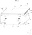
- FIG. 1 is a perspective view of an example of an exterior of a battery module according to the embodiment.
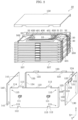
- FIG. 2 is an exploded perspective view of an exterior body of the battery module.
- the Y-axis is the front-back direction
- the positive end of the Y-axis (front end of arrow) is the front side
- the negative end of the Y-axis (rear end of arrow) is the rear side for the sake of description.
- the Z-axis is the top-bottom direction
- the positive end of the Z-axis (front end of arrow) is the upper side
- the negative end of the Z-axis (rear end of arrow) is the lower side.
- the X-axis is defined by applying the Y-axis and the Z-axis as defined above to a right-handed coordinate system.
- a direction perpendicular to the Y-axis and the Z-axis is the Y-axis
- the positive end of the X-axis front end of arrow
- the negative end of the X-axis rear end of arrow
- battery module 10 includes first module reinforcement plates 110 and 120, and battery stack 200.
- Battery module 10 may further include second module reinforcement plates 130 and 140, cover 150, circuit board 400, external terminal 20, and communication terminal 30.
- Battery stack 200 is, for example, a hexahedron.
- First module reinforcement plate 110 is a metallic, tabular component disposed at the positive end of the Y-axis of battery module 10.
- First module reinforcement plate 110 is disposed in at least a position, included in positions that cover a plurality of outer surfaces (plurality of lateral surfaces) excluding a pair of outer surfaces (upper surface and lower surface) at both outer sides along a lamination direction of battery stack 200, that substantially covers an entirety of a outer surface (in the present embodiment, outer surface at the positive end of the Y-axis) having a maximum area.
- Plurality of outer surfaces excluding a pair of outer surfaces at both outer sides along a lamination direction of battery stack 200 here means a plurality of lateral surfaces that intersect (in the present embodiment, are orthogonal) with the upper surface and lower surfaces that are the pair of outer surfaces.
- first module reinforcement plate 110 does not strictly need to cover the entirety of the outer surface of battery stack 200 at the positive end of the Y-axis, and may also, for example, expose a portion of at most 10% of the entire surface.
- First module reinforcement plate 110 is substantially rectangular in a plan view.
- First module reinforcement plate 110 may include protrusions 111 protruding toward the positive end of the Y-axis.
- Two protrusions 111 are disposed along the X-axis and are, for example, substantially cuboid.
- Protrusion 111 may be a portion formed by performing a stamping treatment on the metallic, tabular component being first module reinforcement plate 110.
- a side opposite to protrusions 111 (negative end of Y-axis) may include recesses corresponding to the shape of each protrusion 111.
- Protrusions 111 are not limited to being two protrusions, but may also be one protrusion and may also be at least three protrusions.
- First module reinforcement plate 110 may have two cutouts 112 in a lower end thereof.
- the two cutouts 112 are rectangular and are disposed along the X-axis.
- First module reinforcement plate 110 may include three hooks 113 extending from an upper end and the lower end thereof toward the negative end of the Y-axis.
- Hooks 113 include a portion facing a surface of battery stack 200 at the positive end of the Z-axis and a portion facing a surface of battery stack 200 at the negative end of the Z-axis.
- hooks 113 may be hooked to at least one of the surface of battery stack 200 at the positive end of the Z-axis and the surface of battery stack 200 at the negative end of the Z-axis, and may be at least one hook. Since hooks 113 are disposed on at least a portion of each length of first module reinforcement plate 110 along the X-axis, it is possible to improve stiffness with respect to stress along the X-axis.
- First module reinforcement plate 110 may include two hooks 114 extending from a right end and a left end thereof toward the negative end of the Y-axis.
- Hooks 114 include a portion facing a surface of battery stack 200 at the positive end of the X-axis and a portion facing a surface of battery stack 200 at the negative end of the X-axis. Hooks 114 are disposed across each width of first module reinforcement plate 110 along the Z-axis. This makes it possible to improve stiffness of first module reinforcement plate 110 with respect to stress along the Z-axis.
- First module reinforcement plate 110 has four through-holes 115 at four corners and along a thickness thereof. As illustrated in FIG. 1 , first module reinforcement plate 110 is fixed to battery stack 200 by fasteners 171, e.g. screws, being fixed to battery stack 200 in a state in which fasteners 171 pass through the four through-holes 115.
- fasteners 171 e.g. screws
- First module reinforcement plate 120 is a metallic, tabular component disposed at the negative end of the Y-axis of battery module 10. First module reinforcement plate 120 faces first module reinforcement plate 110 and substantially covers an entirety of an outer surface of battery stack 200 at the negative end of the Y-axis. Note that first module reinforcement plate 110 corresponds to a first reinforcement plate and first module reinforcement plate 120 corresponds to a second reinforcement plate. First module reinforcement plate 120 differs from first module reinforcement plate 110 in that first module reinforcement plate 120 is disposed on the other side of battery stack 200 and does not include protrusions 111. In other words, first module reinforcement plate 120 includes cutouts 122, hooks 123 and 124, and through-holes 125. This configuration corresponds respectively to cutouts 112, hooks 113 and 114, and through-holes 115 of first module reinforcement plate 110. Accordingly, detailed description of first module reinforcement plate 120 is omitted.
- Second module reinforcement plate 130 is a metallic, tabular component disposed at the negative end of the X-axis of battery module 10. Second module reinforcement plate 130 covers an outer surface of battery stack 200 at the negative end of the X-axis. The outer surface at the negative end of the X-axis is, among lateral surfaces of battery stack 200, a lateral surface without a maximum area. Second module reinforcement plate 130 is a rectangular, tabular component, and has opening 131 exposing input-output terminal 401, opening 132 exposing communication terminal 30, and through-holes 133. As illustrated in FIG. 1 , second module reinforcement plate 130 is fixed to battery stack 200 by fasteners 171, e.g. screws, being fixed to battery stack 200 in a state in which fasteners 171 pass through the four through-holes 133.
- fasteners 171 e.g. screws
- Second module reinforcement plate 140 is a metallic, tabular component disposed at the positive end of the X-axis of battery module 10. Second module reinforcement plate 140 faces second module reinforcement plate 130 and covers an outer surface of battery stack 200 at the positive end of the X-axis. The outer surface at the positive end of the X-axis is, among the lateral surfaces of battery stack 200, a lateral surface without a maximum area. Second module reinforcement plate 140 is a rectangular, tabular component and has through-holes 141. Similar to second module reinforcement plate 130, second module reinforcement plate 140 is fixed to battery stack 200 by fasteners 171, e.g. screws, being fixed to battery stack 200 in a state in which fasteners 171 pass through the four through-holes 141.
- fasteners 171 e.g. screws
- Cover 150 is disposed at the positive end of the Z-axis of battery module 10, and is a metallic, tabular component. Cover 150 covers circuit board 400 disposed at the positive end of the Z-axis of battery stack 200. Cover 150 is substantially rectangular in the plan view.
- first module reinforcement plates 110 and 120, and second module reinforcement plates 130 and 140 are disposed in positions that cover the plurality of outer surfaces (plurality of lateral surfaces) excluding the pair of outer surfaces (upper surface and lower surface) at both outer sides along the lamination direction of battery stack 200.
- first module reinforcement plates 110 and 120 and second module reinforcement plates 130 and 140 do not need to cover the outer surfaces of battery stack 200 at either end of the Z-axis.
- Battery stack 200 includes the tabular cells 220 laminated on one another. A configuration of battery stack 200 will be described in more detail later.
- Circuit board 400 is disposed on tabular tray 320 that is a tabular component covering the upper surface of battery stack 200.
- Tabular tray 320 is disposed on the upper surface side of battery stack 200.
- Circuit board 400 includes a control circuit that controls an output of electric power stored in battery stack 200, performs charge control of battery stack 200, etc.
- circuit board 400 includes input-output terminal 401 that is electrically connected to the electrode terminal of each cell 220. Input-output terminal 401 is electrically connected to the electrode terminal of each cell 220 in order to obtain an intermediate potential of battery stack 200.
- External terminal 20 is a terminal for outputting the electric power (discharge) stored in battery stack 200, inputting external electric power (charge) to battery stack 200, etc.
- external terminal 20 is connected to an external device to be a load, or connected to a device, system power supply, etc. that outputs electric power of a power generator, etc.
- External terminal 20 is electrically connected to circuit board 400 by power line 21, and is electrically connected, via circuit board 400, to (i) a positive electrode terminal of the cell located at an end portion of battery stack 200 near its positive electrode (hereinafter referred to as "positive electrode terminal of battery stack 200") and (ii) a negative electrode terminal of the cell located at an end portion of battery stack 200 near its negative electrode (hereinafter referred to as "negative electrode terminal of battery stack 200").
- Circuit board 400 is electrically connected to the positive electrode terminal of battery stack 200 with positive electrode power line 23 and to the negative electrode terminal of battery stack 200 with negative electrode power line 22.
- external terminal 20 is electrically connected to the positive electrode terminal and the negative electrode terminal of battery stack 200 via circuit board 400, but is not limited thereto, and may also be directly electrically connected to the positive electrode terminal and the negative electrode terminal of battery stack 200 with each power line.
- Communication terminal 30 is a terminal for obtaining a control signal from an external device, outputting a signal that indicates a state of battery module 10 to an external device, etc.
- Communication terminal 30 is electrically connected to circuit board 400 by communication line 31.
- Circuit board 400 obtains the control signal from the external device via communication terminal 30, outputs the signal that indicates the state of battery module 10 via communication terminal 30, etc.
- external terminal 20 and communication terminal 30 are disposed along the Y-axis on a surface at the negative end of the X-axis of battery module 10.
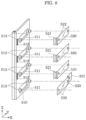
- FIG. 3 is an exploded perspective view for describing the battery stack.
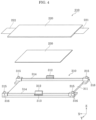
- FIG. 4 is an exploded perspective view of an example of a configuration of the cell and the tabular tray that form one unit of a laminate of the battery stack.
- battery stack 200 is an assembly of the tabular cells 220 laminated on one another.
- battery stack 200 is an assembly of plate 210 as single unit that includes one cell 220 and tabular tray 310 to which the main surface of the one cell 220 is fixed.
- battery stack 200 is an assembly of cell 220 and tabular tray 310 being alternatingly laminated on each other.
- the positive electrode terminal of one cell 220 and the negative electrode terminal of another cell 220 are respectively electrically connected to each other by connection units 501 and 502.
- plate 210 includes, to be specific, cell 220, double-sided tape 230, and tabular tray 310.
- An interior of cell 220 includes a power generation element in which a rectangular positive electrode, a separator, negative electrode, and separator are respectively and repeatedly laminated on one another.
- Cell 220 includes, for example, a laminate that covers an outer surface of the power generation element.
- an exterior body of cell 220 includes the laminate.
- Cell 220 includes positive electrode terminal 221 that is electrically connected to the positive electrode of the power generation element and exposed at the negative end of the X-axis, and negative electrode terminal 222 that is electrically connected to the negative electrode of the power generation element and exposed at the positive end of the X-axis.
- Positive electrode terminal 221 and negative electrode terminal 222 are metallic, tabular components.
- cell 220 has a configuration in which positive electrode terminal 221 and negative electrode terminal 222 are exposed at opposite ends of the X-axis, but is not limited to this configuration, and may have a configuration in which the positive electrode terminal and the negative electrode terminal are exposed at the same side.
- the positive electrode terminal and the negative electrode terminal may also be disposed in overlapping positions in a top view when multiple cells are vertically stacked on one another.
- cell 220 may have a configuration in which positive electrode terminals and negative electrode terminals are disposed in point-symmetric positions, so that the positive electrode terminal of one cell and the negative electrode terminal of another cell overlap and the negative electrode terminal of the one cell and the positive electrode terminal of the other cell overlap when the one cell and the other cell that is the one cell upside down are stacked on each other. This makes it possible to easily connect multiple cells in series.
- Double-sided tape 230 is disposed between cell 220 and tabular tray 310, and fixes cell 220 to a predetermined position of tabular tray 310. Either side of double-sided tape 230 may be adhesive. Note that instead of double-sided tape 230, cell 220 may also be fixed to the predetermined position of tabular tray 310 using adhesive.
- Tabular tray 310 includes tray body 311, connector 312, recess 313, partition 314, protrusion 315, and fixing hole 316.
- Tray body 311 is a rectangular, tabular portion on which cell 220 is placed.
- Connector 312 is disposed on either end of tray body 311 along the Y-axis, and includes two portions extending toward the positive end of the Z-axis.
- the two connectors 312 are hook-shaped portions protruding inward along the Y-axis, each having a distal end at the positive end of the Z-axis for hooking to the outer sides along the Y-axis.
- Recess 313 is a portion into which the hook-shaped distal end of connector 312 and is recessed inward along the Y-axis.
- Recess 313 is, for example, formed at either end of the Y-axis, open facing in the direction of the Y-axis, and is a substantially cuboid hole with its length along the X-axis.
- connector 312 and recess 313 Detailed functionality of connector 312 and recess 313 will be described later.
- Partition 314 is disposed at either end of tray body 311 along the Y-axis, protrudes toward the positive end of the Z-axis, and includes a pair of portions formed across the lengths of tray body 311 along the X-axis.
- An interval between the pair of partitions 314 corresponds to a width of cell 220 along the Y-axis, and is longer than the width of cell 220 along the Y-axis for only a predetermined clearance amount. Accordingly, it is possible to easily position the pair of partitions 314 on tabular tray 310 of cell 220 along the Y-axis.
- Protrusion 315 is a portion that is disposed in each of four corners of tray body 311 and protrudes toward the positive end of the Z-axis.
- Protrusion 315 is, for example, columnar.
- Protrusions 315 engage with holes not illustrated that are formed in another tabular tray 310 disposed on tabular tray 310. In other words, protrusion 315 is inserted in a bottom of the other tabular tray 310. With this, tabular trays 310 are restricted in movement along the X-axis and the Y-axis when tabular trays 310 are stacked on one another.
- Fixing hole 316 is disposed in each of the four corners of tabular tray 310, and is a hole in which fastener 171 is fixed at either end of the X-axis and either end of the Y-axis. In other words, fixing hole 316 is disposed in two surfaces of the outer side of the four corners. Fixing hole 316 includes, for example, a female screw into which a male screw formed on a distal end of fastener 171 is screwed.
- tabular tray 320 which has the same configuration as tabular tray 310, is disposed at the positive end of the Z-axis of battery stack 200.
- Tabular tray 320 corresponds to a tabular component.
- Circuit board 400 is disposed on tabular tray 320.
- Tabular tray 330 at the farthest negative end of the Z-axis of battery stack 200 differs from tabular tray 310 in that tabular tray 330 further includes grooves 337 on a bottom of tray body 311 thereof extending along the Y-axis. Any other configurational elements of tabular tray 330 are the same as configurational elements of tabular tray 310, and description thereof is omitted.
- Groove 337 is formed at two different positions along the X-axis on tray body 311 of tabular tray 330 and is formed across an entire span of the Y-axis of tray body 311. Groove 337 is disposed in a position overlapping cutouts 112 of first module reinforcement plate 110 along the Y-axis in a state in which first module reinforcement plate 110 is disposed at the positive end of the Y-axis.
- First module reinforcement plates 110 and 120, and second module reinforcement plates 130 and 140 are fixed to tabular tray 320 disposed at the positive end of the Z-axis of battery stack 200, and tabular tray 330 disposed at the negative end of the Z-axis of battery stack 200. With this, first module reinforcement plates 110 and 120, and second module reinforcement plates 130 and 140 maintain plates 210 and tabular tray 320 of battery stack 200 in a laminated state.
- electrode terminals 221 and 222 of cell 220 are bent.
- FIG. 5 is a diagram for describing a process in which each electrode terminal on the plate is bent.
- (a) of FIG. 5 is a perspective view of the plate before each of the electrode terminals are bent, and (b) of FIG. 5 is a perspective view of the plate after each of the electrode terminals are bent.
- positive electrode terminal 221 of cell 220 is bent as to point toward the negative end of the Z-axis
- negative electrode terminal 222 is bent as to point toward the positive end of the Z-axis opposite to positive electrode terminal 221.
- positive electrode terminal 221 and negative electrode terminal 222 respectively include first plates 221a and 222a that extend along the main surface of cell 220, and second plates 221b and 222b that extend substantially perpendicular to the main surface.
- a direction in which second plate 221b of positive electrode terminal 221 extends with respect to first plate 221a and a direction in which second plate 222b of negative electrode terminal 222 extends with respect to first plate 222a are opposite.
- FIG. 6 is a diagram for describing the process in which two plates are laminated on each other.
- (a) of FIG. 6 is a perspective view of a state before the two plates are laminated on each other, and
- (b) of FIG. 6 is a perspective view of a state after the two plates have been laminated on each other.
- the two plates 210 are disposed so that positive electrode terminal 221 and negative electrode terminal 222 of each cell 220 face in different directions.
- positive electrode terminal 221 is disposed at the negative end of the X-axis and negative electrode terminal 222 is disposed at the positive end of the X-axis.
- positive electrode terminal 221 is disposed at the positive end of the X-axis and negative electrode terminal 222 is disposed at the negative end of the X-axis.
- battery stack 200 is assembled by laminating seven plates 210 on one another so that two adjacent and overlapping plates 210 have the same configuration as above.
- connection units 501 and 502 that mutually connect each electrode terminal of the seven laminated plates 210 will be described next.
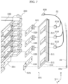
- FIG. 7 is a diagram for describing a placement position of the connection unit on the battery stack.
- FIG. 8 is a diagram for describing the configuration of the connection unit.
- FIG. 9 is a diagram for describing a process in which the electrode terminals of the cells are connected.
- connection units 501 and 502 are disposed on sides of laminated plates 210 where electrode terminals 221 and 222 are exposed.
- connection unit 501 is disposed at the negative end of X-axis of plates 210
- connection unit 502 is disposed at the positive end of the X-axis of plates 210. Since connection unit 501 and connection unit 502 have the same configuration, connection unit 501 disposed on the negative end of the X-axis of plate 210 will be described here.
- connection unit 501 includes placement plate 510 and metal plates 520 and 530.
- Placement plate 510 is a substantially rectangular, tabular component and includes openings 511 and 512, and protrusions 513.
- Openings 511 are rectangular with their length along the Y-axis, and are arranged along the Z-axis. Openings 511 are disposed at positions corresponding to electrode terminals 221 and 222 of the laminated plates 210. Openings 511 correspond in size to second plates 221b and 222b of electrode terminals 221 and 222.
- Openings 512 are rectangular openings with their lengths along the Z-axis, and are slit-shaped openings disposed more toward the negative end of the Y-axis with respect to three openings 511 closer to the positive end of the Z-axis among openings 511. Openings 512 each have substantially the same width along the Z-axis as openings 511.
- Protrusions 513 are columnar portions disposed at either outer side of openings 511 along the Y-axis and protrude toward the X-axis. In other words, two protrusions 513 are disposed corresponding to each position on the Z-axis along which openings 511 are disposed.
- Metal plates 520 are rectangular, metallic components with their lengths along the Y-axis.
- Metal plates 520 each include a metallic connector joint 521 that extends from an end portion thereof at the negative end of the Y-axis toward the negative end of the X-axis, and two through-holes 522 disposed at either end of each of metal plates 520 along the Y-axis.
- Metal plates 520 are disposed at positions corresponding to the three openings 511 in placement plate 510 closer to the positive end of Z-axis. With this, on each of metal plates 520, connector joint 521 passes through opening 512 of placement plate 510 and protrusions 513 pass through the two through-holes 522. As stated above, metal plates 520 cover the three corresponding openings 511 when metal plates 520 are disposed on placement plate 510.
- Metal plate 530 is a rectangular, metallic component with its length along the Y-axis.
- Metal plate 530 includes terminal 531 that is bent in steps toward the negative end of the X-axis starting from an end portion thereof at the positive end of the Y-axis, and two through-holes 532 disposed on either end of metal plate 530 along the Y-axis.
- Metal plate 530 is disposed at a position that corresponds to opening 511 disposed at the farthest negative end of the Z-axis of placement plate 510. With this, on metal plate 530, terminal 531 is disposed at a position closer to the negative end of X-axis than placement plate 510, and protrusions 513 pass through the two through-holes 532.
- metal plate 530 covers the corresponding opening 511 when metal plate 530 is disposed on placement plate 510.
- the laminated plates 210 include four portions at the negative end of the X-axis where electrode terminals 221 and 222 are exposed. Three portions closer to the positive end of the Z-axis among the four portions are each a combination of positive electrode terminal 221 and negative electrode terminal 222 that overlap each other along the X-axis due to plates 210 being laminated on one another. A portion closest to the negative end of the Z-axis among the four portions is only negative electrode terminal 222 that does not overlap positive electrode terminal 221.
- metal plates 520 and 530 and each of electrode terminals 221 and 222 overlap one another along the X-axis since openings 511 and 512 of placement plate 510 are disposed at positions corresponding to each of electrode terminals 221 and 222 of the laminated plates 210. More specifically, metal plates 520 overlap, along the X-axis, the three portions closer to the positive end of the Z-axis among the four portions where electrode terminals 221 and 222 of plates 210 are exposed. Metal plate 530 overlaps, along the X-axis, the portion closest to the negative end of the Z-axis among the four portions where electrode terminals 221 and 222 of plates 210 are exposed. In other words, it is possible to dispose metal plates 520 and 530 lateral to the four portions where electrode terminals 221 and 222 are exposed by disposing connection unit 501 at the negative end of the X-axis of the laminated plates 210.
- positive electrode terminals 221, negative electrode terminals 222, and metal plates 520 are mutually electrically connected by performing laser beam welding on metal plates 520.
- negative electrode terminal 222 and metal plate 530 are mutually electrically connected by performing laser beam welding on metal plate 530.
- connector joint 521 of metal plates 520 is each electrically connected to a corresponding one of connectors 610 (three in the present embodiment).
- Connectors 610 are each electrically connected to connector 620 via communication line 32.
- Connector 620 is electrically connected to input-output terminal 401 disposed on circuit board 400.
- circuit board 400 is capable of obtaining an intermediate potential of battery stack 200 via input-output terminal 401.
- Tip 22a of negative electrode power line 22 is electrically connected to terminal 531 of metal plate 530.
- communication line 32 and negative electrode power line 22 are disposed along the Z-axis on either end of placement plate 510 along the Y-axis.
- communication line 32 and negative electrode power line 22 are disposed on opposite sides along the Y-axis and metal plates 520 and 530 are interposed therebetween. Accordingly, it is possible to reduce adverse effects of an electromagnetic field produced from negative electrode power line 22 on communication line 32 due to the electromagnetic field produced from negative electrode power line 22 being absorbed by metal plates 520 and 530.
- a configuration of an electric connection of battery stack 200 and circuit board 400 will be described with reference to FIG. 10 .
- FIG. 10 is a schematic view for describing the electrical connection of the battery module.
- the laminated plates 210 are laminated on one another so that the negative electrode and the positive electrode of each of cells 220 are laminated on one another alternatingly.
- a distal end of positive electrode terminal 221 is bent as to point upward
- a distal end of negative electrode terminal 222 is bent as to point downward. Accordingly, at the negative end of the X-axis, three portions where positive electrode terminal 221 and negative electrode terminal 222 overlap each other are disposed from the positive end of the Z-axis, and closest to the negative end of the Z-axis, only negative electrode terminal 222 is disposed.
- connection unit 502 disposed at the positive end of the X-axis has a configuration that is the configuration of connection unit 501 with its Z-axis orientation upside down. As illustrated in FIG. 10 , this makes it possible to dispose metal plates 520 and 530 at positions corresponding to electrode terminals 221 and 222 at the positive end of the X-axis of the laminated plates 210.
- Connection unit 502 similar to connection unit 501, includes connectors 610 for obtaining the intermediate potential of the portions where positive electrode terminal 221 and negative electrode terminal 222 overlap each other, and is connected to circuit board 400 by communication line 32.
- positive electrode terminal 221 disposed closest to the positive end of the Z-axis is electrically connected to tip 23a of positive electrode power line 23 via metal plate 530.
- first module reinforcement plates 110 and 120, and second module reinforcement plates 130 and 140 are fixed, with fasteners 171, to fixing holes 316 of (i) tabular tray 310 disposed closest to the positive end of the Z-axis of the laminated plates 210 and (ii) tabular tray 330 disposed closest to the negative end of the Z-axis.
- the laminated plates 210 are restricted from moving away from one another along the Z-axis, and from being out of alignment along the X-axis and the Y-axis.
- a configuration of electricity storage unit 1 will be described next with reference to FIG. 11 .
- FIG. 11 is a perspective view for describing the configuration of electricity storage unit 1.
- Electricity storage unit 1 includes battery modules 10 (two in the present embodiment) and casing 700 that accommodates battery modules 10. Battery modules 10 each have the above-mentioned configuration.
- Casing 700 includes opening 701 for accommodating battery module 10 in an inner space of casing 700, and door 702 that can cover and uncover opening 701.
- Casing 700 may also include opening 703 for performing wiring of battery module 10, and door 704 for covering and uncovering opening 703.
- Casing 700 includes placement surfaces 710 (two in the present embodiment) for placing battery modules 10 in the inner space of casing 700, and guides 720 that are formed on placement surfaces 710 and are ribs extending along the Y-axis. Guides 720 are disposed on placement surfaces 710 along the X-axis.
- Cutouts 112 and grooves 337 in a bottom of battery module 10 are formed at positions corresponding to guides 720.
- battery modules 10 each include guides 720 corresponding to first guides, and cutouts 112 and grooves 337 that engage with guides 720 as second guides.
- first guides formed on placement surfaces 710 are ribs, but may also be grooves extending along the Y-axis.
- the second guides are ribs that engage with the first guides in battery module.
- Electricity storage unit 1 may further include module fixing plate 730 that fixes battery module 10 at a predetermined position on placement surface 710.
- Module fixing plate 730 is a rectangular, tabular component with its length along the X-axis that is longer along the X-axis than battery module 10.
- Module fixing plate 730 has two openings 731 into which the two protrusions 111 formed on first module reinforcement plate 110 of battery module 10 fit. In other words, the two protrusions 111 correspond to second fittings and the two openings 731 correspond to first fittings. Note that as long as module fixing plate 730 has a number of openings 731 corresponding to the number of protrusions 111, the number of openings 731 is not limited to two.
- Module fixing plate 730 has two through-holes 732 that are each disposed on either end of the X-axis, and is fixed to casing 700 by fixing fasteners, which are not illustrated, to fixing holes 705 of casing 700 in a state in which the fasteners pass through module fixing plate 730.
- Module fixing plate 730 restricts movement of battery module 10 toward the positive end of the Y-axis by being fixed to casing 700 in the state in which battery module 10 is placed on placement surface 710 at the predetermined position.
- battery module 10 includes battery stack 200 and first module reinforcement plates 110 and 120.
- Battery stack 200 includes the tabular cells 220 laminated on one another.
- First module reinforcement plates 110 and 120 are metallic components disposed in at least a position, included in positions that cover the plurality of outer surfaces excluding the pair of first outer surfaces at both outer sides along the lamination direction of battery stack 200, that substantially covers an entirety of a second outer surface having a maximum area.
- first module reinforcement plates 110 and 120 This enables first module reinforcement plates 110 and 120 to effectively limit mutual misalignment of cells 220 along crossing directions since first module reinforcement plates 110 and 120 are disposed on the outer surfaces having a maximum area among the outer surfaces that face in crossing directions perpendicular to the lamination direction of battery stack 200.
- Battery module 10 further includes tabular tray 320.
- Tabular tray 320 covers an upper surface that is one surface of the pair of first outer surfaces.
- First module reinforcement plates 110 and 120 are fixed to tabular tray 320.
- battery stack 200 is a laminate of a plurality of units each including one cell 220 and tabular trays 310 and 330 to which the main surface of the one cell 220 is fixed.
- First module reinforcement plates 110 and 120 are fixed to tabular tray 330 disposed on the other surface of the pair of first outer surfaces.
- first module reinforcement plate 110 is capable of restricting cells 220 from moving away from one another along the lamination direction of battery stack 200.
- Battery module 10 further includes circuit board 400 that is disposed on tabular tray 320 and includes input-output terminal 401 electrically connected to positive electrode terminal 221 and negative electrode terminal 222 that are electrode terminals of each of cells 220.
- first module reinforcement plate 110 includes first module reinforcement plate 110 that covers the second outer surface, and first module reinforcement plate 120 that faces the second outer surface and substantially covers an entirety of a third outer surface of battery stack 200.
- first module reinforcement plates 110 and 120 respectively include hooks 113 and 123 that hook to at least one of the pair of first outer surfaces.
- first module reinforcement plates 110 and 120 include a second guide that is groove 337 on an outer surface and extending in a predetermined direction, groove 337 fitting guides 720 that is a first rib formed on placement surfaces 710 on which battery module 10 is placed and extending in the predetermined direction.
- each of cells 220 includes positive electrode terminal 221 and negative electrode terminal 222 having a different polarity from positive electrode terminal 221.
- Positive electrode terminal 221 and negative electrode terminal 222 on each of cell 220 respectively include first plates 221a and 222a that extend along the main surface of cell 220, and second plates 221b and 222b that extend substantially perpendicular to the main surface.
- the direction in which second plate 221b of positive electrode terminal 221 extends with respect to first plate 221a and the direction in which second plate 222b of negative electrode terminal 222 extends with respect to first plate 222a are opposite.
- second plate 221b of positive electrode terminal 221 on the first cell and second plate 222b of negative electrode terminal 222 on the second cell are mutually connected.
- first module reinforcement plates 110 and 120 included in battery module 10 do not have any through-holes aside from the four through-holes 115 for being fixed to battery stack 200, but are not limited thereto.
- first module reinforcement plate 110A having through-holes 116 in a region that overlaps a region in which cells 220 are disposed when seen along the Y-axis may also be used.
- first module reinforcement plate 110A may have through-holes 116 that partially expose the second outer surface that intersects the first outer surface facing the lamination direction of battery stack 200.
- first module reinforcement plate 120A disposed on the opposite side of battery stack 200 along the Y-axis may have the same configuration as first module reinforcement plate 110A.
- FIG. 12 is a diagram showing an example of an exterior of the battery module according to Variation 1.
- through-holes 116 may also be disposed between cells 220 included in battery stack 200. In this case, it is easier for air to pass through an interior of battery module 10A and also easier to cool cells 220.
- Through-holes 116 may also be disposed in positions overlapping cells 220 included in battery stack 200 when seen from the Y-axis. In this case, it is possible to reduce foreign substances exterior to battery module 10A from entering the interior of battery module 10A.
- Electricity storage unit 1 has a configuration in which the lamination direction of battery stack 200 is perpendicular to placement surfaces 710 of casing 700, but is not limited thereto, and the lamination direction may also be horizontal.
- the first module reinforcement plate may also be a bottom surface of the battery module.
- the first module reinforcement plate may have grooves into which guides 720 disposed on placement surfaces 710 of casing 700 fit.
- tray body 311 of tabular tray 310 disposed between cells 220 may have openings for accommodating portions where cells 220 expand.
- tray body 311 may also support only a periphery of cell 220. Note that the openings do not need to pass all the way through tray body 311 and may also be recesses.
- a battery module and electricity storage unit according to one or more aspects of the present invention have been described above based on the embodiment, but the present invention is not limited to the foregoing. Forms obtained by various combinations of the components in the different embodiments that can be conceived by a person skilled in the art which are within the scope of the essence of the present invention are also included in the scope of the one or more aspects of the present invention.
Landscapes
- Chemical & Material Sciences (AREA)
- Chemical Kinetics & Catalysis (AREA)
- Electrochemistry (AREA)
- General Chemical & Material Sciences (AREA)
- Engineering & Computer Science (AREA)
- Manufacturing & Machinery (AREA)
- Microelectronics & Electronic Packaging (AREA)
- Battery Mounting, Suspending (AREA)
- Connection Of Batteries Or Terminals (AREA)
Description
- The present invention relates to a battery module including multiple cells laminated on one another and an electricity storage unit including the battery module.
- Patent Literature (PTL) 1 discloses a battery pack including a battery stack having multiple battery cells (cells) laminated on one another.
- PTL 1:
Japanese Unexamined Patent Application Publication No. 2014-138483 -
WO 2016/204470 A1 describes a cartridge that is suitable for sensing voltages of battery cells through a central area and an edge, wherein two battery cells are respectively located in an upper part and in a lower part thereof in order to increase energy density; and a battery module having the same. The cartridge according to the present invention comprises: a mount frame having a pair of through-windows positioned successively along the length direction, lower sliding boards positioned successively along the width direction between the pair of through-windows, a lead mounting board and upper sliding boards; and cooling fins for respectively covering the pair of through-windows, wherein the lower sliding board and the upper sliding board are respectively positioned on the left side and the right side of the lead mounting board, and diagonally face one another. -
US 2015/221909 A1 describes a battery pack comprising a battery module made by stacking film-covered batteries with positive- and negative-electrode pull-out tabs being taken out from the same side. A plurality of battery modules are disposed in such a way that, in end surfaces of the battery modules, the sides of film-covered batteries from which positive- and negative-electrode pull-out tabs are pulled out face each other, and the battery modules are electrically connected together with an insulation member disposed between the modules. Side surfaces adjacent to the sides of film-covered batteries from which the positive- and negative-electrode pull-out tabs are pulled out are reinforced by a common reinforcing member. -
JP 2010 123412 A - The technique in
PTL 1 is, however, not capable of effectively limiting misalignment of the cells. - Accordingly, the present invention provides a battery module capable of effectively limiting misalignment of the laminated cells.
- The invention is defined by the independent claims, while preferred embodiments form the subject of the dependent claims.
- A battery module according to an aspect of the present invention includes a battery stack including cells that are tabular and laminated on one another; and a module reinforcement plate that is metallic and disposed in at least a position, included in positions that cover a plurality of outer surfaces excluding a pair of first outer surfaces at both outer sides along a lamination direction of the battery stack, that substantially covers an entirety of a second outer surface having a maximum area.
- An electricity storage unit according to an aspect of the present invention includes the battery module; and a placement surface on which the battery module is placed.
- The battery module of the present invention makes it possible to effectively limit misalignment of the laminated cells.
-
-
FIG. 1 is a perspective view of an example of an exterior of a battery module according to an embodiment. -
FIG. 2 is an exploded perspective view of an exterior body of the battery module. -
FIG. 3 is an exploded perspective view for describing a battery stack. -
FIG. 4 is an exploded perspective view of an example of a configuration of a cell and a tabular tray that form one unit of a laminate of the battery stack. -
FIG. 5 is a diagram for describing a process in which each electrode terminal on a plate is bent. -
FIG. 6 is a diagram for describing a process in which two plates are laminated on each other. -
FIG. 7 is a diagram for describing a placement position of a connection unit on the battery stack. -
FIG. 8 is a diagram for describing a configuration of the connection unit. -
FIG. 9 is a diagram for describing a process in which electrode terminals of the cells are connected. -
FIG. 10 is a schematic view for describing electrical connections of the battery module. -
FIG. 11 is a perspective view of an example of a configuration of an electricity storage unit including the battery module. -
FIG. 12 is diagram of an example of an exterior of a battery module according toVariation 1. - Hereinafter, a battery module according to an embodiment will be described with reference to the drawings. Note that each of the embodiments described below shows a comprehensive or specific example in the present invention. Numerical values, shapes, materials, components, placement and connection of the components, steps and their order, and the like are mere examples and are not intended to limit the present invention. Components in the following embodiments not mentioned in any of the independent claims that define the broadest concepts are described as optional elements.
- Note that the drawings are schematic diagrams and do not necessarily provide strictly accurate illustrations. In the drawings, components that are substantially the same as components described previous thereto have the same reference numerals and overlapping descriptions may be omitted or simplified.
- Hereinafter, the embodiment will be described with reference to
FIG. 1 to FIG. 11 . -
FIG. 1 is a perspective view of an example of an exterior of a battery module according to the embodiment.FIG. 2 is an exploded perspective view of an exterior body of the battery module. - Note that in these and subsequent drawings, the Y-axis is the front-back direction, the positive end of the Y-axis (front end of arrow) is the front side, and the negative end of the Y-axis (rear end of arrow) is the rear side for the sake of description. The Z-axis is the top-bottom direction, the positive end of the Z-axis (front end of arrow) is the upper side, and the negative end of the Z-axis (rear end of arrow) is the lower side. The X-axis is defined by applying the Y-axis and the Z-axis as defined above to a right-handed coordinate system. In other words, a direction perpendicular to the Y-axis and the Z-axis (left-right direction) is the Y-axis, the positive end of the X-axis (front end of arrow) is the left side, and the negative end of the X-axis (rear end of arrow) is the right side.
- As illustrated in
FIG. 1 andFIG. 2 ,battery module 10 includes firstmodule reinforcement plates battery stack 200.Battery module 10 may further include secondmodule reinforcement plates cover 150,circuit board 400,external terminal 20, andcommunication terminal 30.Battery stack 200 is, for example, a hexahedron. - First
module reinforcement plate 110 is a metallic, tabular component disposed at the positive end of the Y-axis ofbattery module 10. Firstmodule reinforcement plate 110 is disposed in at least a position, included in positions that cover a plurality of outer surfaces (plurality of lateral surfaces) excluding a pair of outer surfaces (upper surface and lower surface) at both outer sides along a lamination direction ofbattery stack 200, that substantially covers an entirety of a outer surface (in the present embodiment, outer surface at the positive end of the Y-axis) having a maximum area. Plurality of outer surfaces excluding a pair of outer surfaces at both outer sides along a lamination direction ofbattery stack 200 here means a plurality of lateral surfaces that intersect (in the present embodiment, are orthogonal) with the upper surface and lower surfaces that are the pair of outer surfaces. Note that firstmodule reinforcement plate 110 does not strictly need to cover the entirety of the outer surface ofbattery stack 200 at the positive end of the Y-axis, and may also, for example, expose a portion of at most 10% of the entire surface. Firstmodule reinforcement plate 110 is substantially rectangular in a plan view. - First
module reinforcement plate 110 may includeprotrusions 111 protruding toward the positive end of the Y-axis. Twoprotrusions 111 are disposed along the X-axis and are, for example, substantially cuboid.Protrusion 111 may be a portion formed by performing a stamping treatment on the metallic, tabular component being firstmodule reinforcement plate 110. In other words, a side opposite to protrusions 111 (negative end of Y-axis) may include recesses corresponding to the shape of eachprotrusion 111.Protrusions 111 are not limited to being two protrusions, but may also be one protrusion and may also be at least three protrusions. - First
module reinforcement plate 110 may have twocutouts 112 in a lower end thereof. The twocutouts 112 are rectangular and are disposed along the X-axis. - First
module reinforcement plate 110 may include threehooks 113 extending from an upper end and the lower end thereof toward the negative end of the Y-axis.Hooks 113 include a portion facing a surface ofbattery stack 200 at the positive end of the Z-axis and a portion facing a surface ofbattery stack 200 at the negative end of the Z-axis. Note that hooks 113 may be hooked to at least one of the surface ofbattery stack 200 at the positive end of the Z-axis and the surface ofbattery stack 200 at the negative end of the Z-axis, and may be at least one hook. Sincehooks 113 are disposed on at least a portion of each length of firstmodule reinforcement plate 110 along the X-axis, it is possible to improve stiffness with respect to stress along the X-axis. - First
module reinforcement plate 110 may include twohooks 114 extending from a right end and a left end thereof toward the negative end of the Y-axis.Hooks 114 include a portion facing a surface ofbattery stack 200 at the positive end of the X-axis and a portion facing a surface ofbattery stack 200 at the negative end of the X-axis.Hooks 114 are disposed across each width of firstmodule reinforcement plate 110 along the Z-axis. This makes it possible to improve stiffness of firstmodule reinforcement plate 110 with respect to stress along the Z-axis. - First
module reinforcement plate 110 has four through-holes 115 at four corners and along a thickness thereof. As illustrated inFIG. 1 , firstmodule reinforcement plate 110 is fixed tobattery stack 200 byfasteners 171, e.g. screws, being fixed tobattery stack 200 in a state in whichfasteners 171 pass through the four through-holes 115. - First
module reinforcement plate 120 is a metallic, tabular component disposed at the negative end of the Y-axis ofbattery module 10. Firstmodule reinforcement plate 120 faces firstmodule reinforcement plate 110 and substantially covers an entirety of an outer surface ofbattery stack 200 at the negative end of the Y-axis. Note that firstmodule reinforcement plate 110 corresponds to a first reinforcement plate and firstmodule reinforcement plate 120 corresponds to a second reinforcement plate. Firstmodule reinforcement plate 120 differs from firstmodule reinforcement plate 110 in that firstmodule reinforcement plate 120 is disposed on the other side ofbattery stack 200 and does not includeprotrusions 111. In other words, firstmodule reinforcement plate 120 includescutouts 122, hooks 123 and 124, and through-holes 125. This configuration corresponds respectively tocutouts 112, hooks 113 and 114, and through-holes 115 of firstmodule reinforcement plate 110. Accordingly, detailed description of firstmodule reinforcement plate 120 is omitted. - Second
module reinforcement plate 130 is a metallic, tabular component disposed at the negative end of the X-axis ofbattery module 10. Secondmodule reinforcement plate 130 covers an outer surface ofbattery stack 200 at the negative end of the X-axis. The outer surface at the negative end of the X-axis is, among lateral surfaces ofbattery stack 200, a lateral surface without a maximum area. Secondmodule reinforcement plate 130 is a rectangular, tabular component, and hasopening 131 exposing input-output terminal 401, opening 132 exposingcommunication terminal 30, and through-holes 133. As illustrated inFIG. 1 , secondmodule reinforcement plate 130 is fixed tobattery stack 200 byfasteners 171, e.g. screws, being fixed tobattery stack 200 in a state in whichfasteners 171 pass through the four through-holes 133. - Second
module reinforcement plate 140 is a metallic, tabular component disposed at the positive end of the X-axis ofbattery module 10. Secondmodule reinforcement plate 140 faces secondmodule reinforcement plate 130 and covers an outer surface ofbattery stack 200 at the positive end of the X-axis. The outer surface at the positive end of the X-axis is, among the lateral surfaces ofbattery stack 200, a lateral surface without a maximum area. Secondmodule reinforcement plate 140 is a rectangular, tabular component and has through-holes 141. Similar to secondmodule reinforcement plate 130, secondmodule reinforcement plate 140 is fixed tobattery stack 200 byfasteners 171, e.g. screws, being fixed tobattery stack 200 in a state in whichfasteners 171 pass through the four through-holes 141. - Cover 150 is disposed at the positive end of the Z-axis of
battery module 10, and is a metallic, tabular component. Cover 150 coverscircuit board 400 disposed at the positive end of the Z-axis ofbattery stack 200. Cover 150 is substantially rectangular in the plan view. - In this manner, first
module reinforcement plates module reinforcement plates battery stack 200. In other words, firstmodule reinforcement plates module reinforcement plates battery stack 200 at either end of the Z-axis. -
Battery stack 200 includes thetabular cells 220 laminated on one another. A configuration ofbattery stack 200 will be described in more detail later. -
Circuit board 400 is disposed ontabular tray 320 that is a tabular component covering the upper surface ofbattery stack 200.Tabular tray 320 is disposed on the upper surface side ofbattery stack 200.Circuit board 400 includes a control circuit that controls an output of electric power stored inbattery stack 200, performs charge control ofbattery stack 200, etc. To be specific,circuit board 400 includes input-output terminal 401 that is electrically connected to the electrode terminal of eachcell 220. Input-output terminal 401 is electrically connected to the electrode terminal of eachcell 220 in order to obtain an intermediate potential ofbattery stack 200. -
External terminal 20 is a terminal for outputting the electric power (discharge) stored inbattery stack 200, inputting external electric power (charge) tobattery stack 200, etc. In other words,external terminal 20 is connected to an external device to be a load, or connected to a device, system power supply, etc. that outputs electric power of a power generator, etc.External terminal 20 is electrically connected tocircuit board 400 bypower line 21, and is electrically connected, viacircuit board 400, to (i) a positive electrode terminal of the cell located at an end portion ofbattery stack 200 near its positive electrode (hereinafter referred to as "positive electrode terminal ofbattery stack 200") and (ii) a negative electrode terminal of the cell located at an end portion ofbattery stack 200 near its negative electrode (hereinafter referred to as "negative electrode terminal ofbattery stack 200").Circuit board 400 is electrically connected to the positive electrode terminal ofbattery stack 200 with positiveelectrode power line 23 and to the negative electrode terminal ofbattery stack 200 with negativeelectrode power line 22. Note thatexternal terminal 20 is electrically connected to the positive electrode terminal and the negative electrode terminal ofbattery stack 200 viacircuit board 400, but is not limited thereto, and may also be directly electrically connected to the positive electrode terminal and the negative electrode terminal ofbattery stack 200 with each power line. -
Communication terminal 30 is a terminal for obtaining a control signal from an external device, outputting a signal that indicates a state ofbattery module 10 to an external device, etc.Communication terminal 30 is electrically connected tocircuit board 400 bycommunication line 31.Circuit board 400 obtains the control signal from the external device viacommunication terminal 30, outputs the signal that indicates the state ofbattery module 10 viacommunication terminal 30, etc. - Note that
external terminal 20 andcommunication terminal 30 are disposed along the Y-axis on a surface at the negative end of the X-axis ofbattery module 10. - The configuration of
battery stack 200 will be described next with reference toFIG. 3 andFIG. 4 . -
FIG. 3 is an exploded perspective view for describing the battery stack.FIG. 4 is an exploded perspective view of an example of a configuration of the cell and the tabular tray that form one unit of a laminate of the battery stack. - As illustrated in
FIG. 3 ,battery stack 200 is an assembly of thetabular cells 220 laminated on one another. To be specific,battery stack 200 is an assembly ofplate 210 as single unit that includes onecell 220 andtabular tray 310 to which the main surface of the onecell 220 is fixed. In other words,battery stack 200 is an assembly ofcell 220 andtabular tray 310 being alternatingly laminated on each other. Inbattery stack 200, in twoadjacent cells 220 amongcells 220 laminated on one another, the positive electrode terminal of onecell 220 and the negative electrode terminal of anothercell 220 are respectively electrically connected to each other byconnection units - As illustrated in
FIG. 4 ,plate 210 includes, to be specific,cell 220, double-sided tape 230, andtabular tray 310. - An interior of
cell 220 includes a power generation element in which a rectangular positive electrode, a separator, negative electrode, and separator are respectively and repeatedly laminated on one another.Cell 220 includes, for example, a laminate that covers an outer surface of the power generation element. In other words, an exterior body ofcell 220 includes the laminate.Cell 220 includespositive electrode terminal 221 that is electrically connected to the positive electrode of the power generation element and exposed at the negative end of the X-axis, andnegative electrode terminal 222 that is electrically connected to the negative electrode of the power generation element and exposed at the positive end of the X-axis.Positive electrode terminal 221 andnegative electrode terminal 222 are metallic, tabular components. - In the present embodiment,
cell 220 has a configuration in whichpositive electrode terminal 221 andnegative electrode terminal 222 are exposed at opposite ends of the X-axis, but is not limited to this configuration, and may have a configuration in which the positive electrode terminal and the negative electrode terminal are exposed at the same side. The positive electrode terminal and the negative electrode terminal may also be disposed in overlapping positions in a top view when multiple cells are vertically stacked on one another. For example,cell 220 may have a configuration in which positive electrode terminals and negative electrode terminals are disposed in point-symmetric positions, so that the positive electrode terminal of one cell and the negative electrode terminal of another cell overlap and the negative electrode terminal of the one cell and the positive electrode terminal of the other cell overlap when the one cell and the other cell that is the one cell upside down are stacked on each other. This makes it possible to easily connect multiple cells in series. - Double-
sided tape 230 is disposed betweencell 220 andtabular tray 310, and fixescell 220 to a predetermined position oftabular tray 310. Either side of double-sided tape 230 may be adhesive. Note that instead of double-sided tape 230,cell 220 may also be fixed to the predetermined position oftabular tray 310 using adhesive. -
Tabular tray 310 includestray body 311,connector 312,recess 313,partition 314,protrusion 315, and fixinghole 316. -
Tray body 311 is a rectangular, tabular portion on whichcell 220 is placed. -
Connector 312 is disposed on either end oftray body 311 along the Y-axis, and includes two portions extending toward the positive end of the Z-axis. The twoconnectors 312 are hook-shaped portions protruding inward along the Y-axis, each having a distal end at the positive end of the Z-axis for hooking to the outer sides along the Y-axis. -
Recess 313 is a portion into which the hook-shaped distal end ofconnector 312 and is recessed inward along the Y-axis.Recess 313 is, for example, formed at either end of the Y-axis, open facing in the direction of the Y-axis, and is a substantially cuboid hole with its length along the X-axis. - Detailed functionality of
connector 312 andrecess 313 will be described later. -
Partition 314 is disposed at either end oftray body 311 along the Y-axis, protrudes toward the positive end of the Z-axis, and includes a pair of portions formed across the lengths oftray body 311 along the X-axis. An interval between the pair ofpartitions 314 corresponds to a width ofcell 220 along the Y-axis, and is longer than the width ofcell 220 along the Y-axis for only a predetermined clearance amount. Accordingly, it is possible to easily position the pair ofpartitions 314 ontabular tray 310 ofcell 220 along the Y-axis. -
Protrusion 315 is a portion that is disposed in each of four corners oftray body 311 and protrudes toward the positive end of the Z-axis.Protrusion 315 is, for example, columnar.Protrusions 315 engage with holes not illustrated that are formed in anothertabular tray 310 disposed ontabular tray 310. In other words,protrusion 315 is inserted in a bottom of the othertabular tray 310. With this,tabular trays 310 are restricted in movement along the X-axis and the Y-axis whentabular trays 310 are stacked on one another. - Fixing
hole 316 is disposed in each of the four corners oftabular tray 310, and is a hole in whichfastener 171 is fixed at either end of the X-axis and either end of the Y-axis. In other words, fixinghole 316 is disposed in two surfaces of the outer side of the four corners. Fixinghole 316 includes, for example, a female screw into which a male screw formed on a distal end offastener 171 is screwed. - As illustrated in
FIG. 3 ,tabular tray 320, which has the same configuration astabular tray 310, is disposed at the positive end of the Z-axis ofbattery stack 200.Tabular tray 320 corresponds to a tabular component.Circuit board 400 is disposed ontabular tray 320.Tabular tray 330 at the farthest negative end of the Z-axis ofbattery stack 200 differs fromtabular tray 310 in thattabular tray 330 further includesgrooves 337 on a bottom oftray body 311 thereof extending along the Y-axis. Any other configurational elements oftabular tray 330 are the same as configurational elements oftabular tray 310, and description thereof is omitted.Groove 337 is formed at two different positions along the X-axis ontray body 311 oftabular tray 330 and is formed across an entire span of the Y-axis oftray body 311.Groove 337 is disposed in aposition overlapping cutouts 112 of firstmodule reinforcement plate 110 along the Y-axis in a state in which firstmodule reinforcement plate 110 is disposed at the positive end of the Y-axis. - First
module reinforcement plates module reinforcement plates tabular tray 320 disposed at the positive end of the Z-axis ofbattery stack 200, andtabular tray 330 disposed at the negative end of the Z-axis ofbattery stack 200. With this, firstmodule reinforcement plates module reinforcement plates plates 210 andtabular tray 320 ofbattery stack 200 in a laminated state. - As illustrated in
FIG. 4 , upon combiningcell 220 andtabular tray 310, and formingplate 210,electrode terminals cell 220 are bent. -
FIG. 5 is a diagram for describing a process in which each electrode terminal on the plate is bent. (a) ofFIG. 5 is a perspective view of the plate before each of the electrode terminals are bent, and (b) ofFIG. 5 is a perspective view of the plate after each of the electrode terminals are bent. - As illustrated in (b) of
FIG. 5 ,positive electrode terminal 221 ofcell 220 is bent as to point toward the negative end of the Z-axis, andnegative electrode terminal 222 is bent as to point toward the positive end of the Z-axis opposite topositive electrode terminal 221. - With this,
positive electrode terminal 221 andnegative electrode terminal 222 respectively includefirst plates cell 220, andsecond plates second plate 221b ofpositive electrode terminal 221 extends with respect tofirst plate 221a and a direction in whichsecond plate 222b ofnegative electrode terminal 222 extends with respect tofirst plate 222a are opposite. - A process in which
plates 210 are laminated on each other will be described next. -
FIG. 6 is a diagram for describing the process in which two plates are laminated on each other. (a) ofFIG. 6 is a perspective view of a state before the two plates are laminated on each other, and (b) ofFIG. 6 is a perspective view of a state after the two plates have been laminated on each other. - As illustrated in (a) of
FIG. 6 , the twoplates 210 are disposed so thatpositive electrode terminal 221 andnegative electrode terminal 222 of eachcell 220 face in different directions. To be specific, onplate 210 disposed on the upper side of the twoplates 210,positive electrode terminal 221 is disposed at the negative end of the X-axis andnegative electrode terminal 222 is disposed at the positive end of the X-axis. However, onplate 210 disposed on the lower side of the twoplates 210,positive electrode terminal 221 is disposed at the positive end of the X-axis andnegative electrode terminal 222 is disposed at the negative end of the X-axis. - As illustrated in (b) of
FIG. 6 , when the twoplates 210 overlap each other in the above orientation,second plate 221b ofpositive electrode terminal 221 of theupper side plate 210 andsecond plate 222b ofnegative electrode terminal 222 of thelower side plate 210 overlap each other along the X-axis. The hook-shaped distal end of each of the twoconnectors 312 ontabular tray 310 hooks intorecess 313 in the othertabular tray 310 disposed ontabular tray 310. With this,tabular trays 310 are restricted from moving away from one another along the Z-axis whentabular trays 310 are stacked on one another. - In the present embodiment,
battery stack 200 is assembled by laminating sevenplates 210 on one another so that two adjacent and overlappingplates 210 have the same configuration as above. - A configuration of
connection units laminated plates 210 will be described next. -
FIG. 7 is a diagram for describing a placement position of the connection unit on the battery stack.FIG. 8 is a diagram for describing the configuration of the connection unit.FIG. 9 is a diagram for describing a process in which the electrode terminals of the cells are connected. - As illustrated in
FIG. 2 ,connection units laminated plates 210 whereelectrode terminals connection unit 501 is disposed at the negative end of X-axis ofplates 210, andconnection unit 502 is disposed at the positive end of the X-axis ofplates 210. Sinceconnection unit 501 andconnection unit 502 have the same configuration,connection unit 501 disposed on the negative end of the X-axis ofplate 210 will be described here. - As illustrated in
FIG. 7 andFIG. 8 ,connection unit 501 includesplacement plate 510 andmetal plates -
Placement plate 510 is a substantially rectangular, tabular component and includesopenings protrusions 513. - Openings 511 (four in the present embodiment) are rectangular with their length along the Y-axis, and are arranged along the Z-axis.
Openings 511 are disposed at positions corresponding to electrodeterminals laminated plates 210.Openings 511 correspond in size tosecond plates electrode terminals - Openings 512 (three in the present embodiment) are rectangular openings with their lengths along the Z-axis, and are slit-shaped openings disposed more toward the negative end of the Y-axis with respect to three
openings 511 closer to the positive end of the Z-axis amongopenings 511.Openings 512 each have substantially the same width along the Z-axis asopenings 511. - Protrusions 513 (eight in the present embodiment) are columnar portions disposed at either outer side of
openings 511 along the Y-axis and protrude toward the X-axis. In other words, twoprotrusions 513 are disposed corresponding to each position on the Z-axis along whichopenings 511 are disposed. -
Metal plates 520 are rectangular, metallic components with their lengths along the Y-axis.Metal plates 520 each include a metallic connector joint 521 that extends from an end portion thereof at the negative end of the Y-axis toward the negative end of the X-axis, and two through-holes 522 disposed at either end of each ofmetal plates 520 along the Y-axis.Metal plates 520 are disposed at positions corresponding to the threeopenings 511 inplacement plate 510 closer to the positive end of Z-axis. With this, on each ofmetal plates 520, connector joint 521 passes through opening 512 ofplacement plate 510 andprotrusions 513 pass through the two through-holes 522. As stated above,metal plates 520 cover the three correspondingopenings 511 whenmetal plates 520 are disposed onplacement plate 510. -
Metal plate 530 is a rectangular, metallic component with its length along the Y-axis.Metal plate 530 includes terminal 531 that is bent in steps toward the negative end of the X-axis starting from an end portion thereof at the positive end of the Y-axis, and two through-holes 532 disposed on either end ofmetal plate 530 along the Y-axis.Metal plate 530 is disposed at a position that corresponds to opening 511 disposed at the farthest negative end of the Z-axis ofplacement plate 510. With this, onmetal plate 530, terminal 531 is disposed at a position closer to the negative end of X-axis thanplacement plate 510, andprotrusions 513 pass through the two through-holes 532. As stated above,metal plate 530 covers thecorresponding opening 511 whenmetal plate 530 is disposed onplacement plate 510. - As illustrated in
FIG. 7 , thelaminated plates 210 include four portions at the negative end of the X-axis whereelectrode terminals positive electrode terminal 221 andnegative electrode terminal 222 that overlap each other along the X-axis due toplates 210 being laminated on one another. A portion closest to the negative end of the Z-axis among the four portions is onlynegative electrode terminal 222 that does not overlappositive electrode terminal 221. - As illustrated in
FIG. 9 , when attachingconnection unit 501 to thelaminated plates 210,metal plates electrode terminals openings placement plate 510 are disposed at positions corresponding to each ofelectrode terminals laminated plates 210. More specifically,metal plates 520 overlap, along the X-axis, the three portions closer to the positive end of the Z-axis among the four portions whereelectrode terminals plates 210 are exposed.Metal plate 530 overlaps, along the X-axis, the portion closest to the negative end of the Z-axis among the four portions whereelectrode terminals plates 210 are exposed. In other words, it is possible to disposemetal plates electrode terminals connection unit 501 at the negative end of the X-axis of thelaminated plates 210. - At the three portions closer to the positive end of the Z-axis,
positive electrode terminals 221,negative electrode terminals 222, andmetal plates 520 are mutually electrically connected by performing laser beam welding onmetal plates 520. At the portion closest to the negative end of the Z-axis,negative electrode terminal 222 andmetal plate 530 are mutually electrically connected by performing laser beam welding onmetal plate 530. With this, in twocells 220 that are laminated adjacent to each other among the cells,second plate 221b ofpositive electrode terminal 221 on onecell 220 andsecond plate 222b ofnegative electrode terminal 222 on theother cell 220 are mutually connected. - Returning to
FIG. 7 ,connector joint 521 ofmetal plates 520 is each electrically connected to a corresponding one of connectors 610 (three in the present embodiment).Connectors 610 are each electrically connected toconnector 620 viacommunication line 32.Connector 620 is electrically connected to input-output terminal 401 disposed oncircuit board 400. - In other words,
connectors 610 are electrically connected to the portions wherepositive electrode terminals 221 andnegative electrode terminals 222 ofplates 210 overlap one another. Accordingly,circuit board 400 is capable of obtaining an intermediate potential ofbattery stack 200 via input-output terminal 401. -
Tip 22a of negativeelectrode power line 22 is electrically connected toterminal 531 ofmetal plate 530. - Note that, as illustrated in
FIG. 9 ,communication line 32 and negativeelectrode power line 22 are disposed along the Z-axis on either end ofplacement plate 510 along the Y-axis. In other words,communication line 32 and negativeelectrode power line 22 are disposed on opposite sides along the Y-axis andmetal plates electrode power line 22 oncommunication line 32 due to the electromagnetic field produced from negativeelectrode power line 22 being absorbed bymetal plates - A configuration of an electric connection of
battery stack 200 andcircuit board 400 will be described with reference toFIG. 10 . -
FIG. 10 is a schematic view for describing the electrical connection of the battery module. - As illustrated in
FIG. 10 , thelaminated plates 210 are laminated on one another so that the negative electrode and the positive electrode of each ofcells 220 are laminated on one another alternatingly. On each ofcells 220, a distal end ofpositive electrode terminal 221 is bent as to point upward, and a distal end ofnegative electrode terminal 222 is bent as to point downward. Accordingly, at the negative end of the X-axis, three portions wherepositive electrode terminal 221 andnegative electrode terminal 222 overlap each other are disposed from the positive end of the Z-axis, and closest to the negative end of the Z-axis, onlynegative electrode terminal 222 is disposed. At the positive end of the X-axis, three portions wherepositive electrode terminal 221 andnegative electrode terminal 222 overlap each other are disposed from the negative end of the Z-axis, and closes to the positive end of the Z-axis, onlypositive electrode terminal 221 is disposed.Cells 220 are connected in series due to the overlappingpositive electrode terminals 221 andnegative electrode terminals 222 being electrically connected in this state. - Note that at the positive end of the X-axis of
battery stack 200, three portions wherepositive electrode terminal 221 andnegative electrode terminal 222 overlap each other are disposed from the negative end of the Z-axis. Accordingly,connection unit 502 disposed at the positive end of the X-axis has a configuration that is the configuration ofconnection unit 501 with its Z-axis orientation upside down. As illustrated inFIG. 10 , this makes it possible to disposemetal plates terminals laminated plates 210. -
Connection unit 502, similar toconnection unit 501, includesconnectors 610 for obtaining the intermediate potential of the portions wherepositive electrode terminal 221 andnegative electrode terminal 222 overlap each other, and is connected tocircuit board 400 bycommunication line 32. - At the positive end of the X-axis,
positive electrode terminal 221 disposed closest to the positive end of the Z-axis is electrically connected to tip 23a of positiveelectrode power line 23 viametal plate 530. - Returning to
FIG. 2 , firstmodule reinforcement plates module reinforcement plates fasteners 171, to fixingholes 316 of (i)tabular tray 310 disposed closest to the positive end of the Z-axis of thelaminated plates 210 and (ii)tabular tray 330 disposed closest to the negative end of the Z-axis. With this, thelaminated plates 210 are restricted from moving away from one another along the Z-axis, and from being out of alignment along the X-axis and the Y-axis. - A configuration of
electricity storage unit 1 will be described next with reference toFIG. 11 . -
FIG. 11 is a perspective view for describing the configuration ofelectricity storage unit 1. -
Electricity storage unit 1 includes battery modules 10 (two in the present embodiment) andcasing 700 that accommodatesbattery modules 10.Battery modules 10 each have the above-mentioned configuration. - Casing 700 includes
opening 701 for accommodatingbattery module 10 in an inner space ofcasing 700, anddoor 702 that can cover and uncoveropening 701. Casing 700 may also include opening 703 for performing wiring ofbattery module 10, anddoor 704 for covering and uncoveringopening 703. Casing 700 includes placement surfaces 710 (two in the present embodiment) for placingbattery modules 10 in the inner space ofcasing 700, and guides 720 that are formed onplacement surfaces 710 and are ribs extending along the Y-axis.Guides 720 are disposed onplacement surfaces 710 along the X-axis. -
Cutouts 112 andgrooves 337 in a bottom ofbattery module 10 are formed at positions corresponding to guides 720. In other words,battery modules 10 each include guides 720 corresponding to first guides, andcutouts 112 andgrooves 337 that engage withguides 720 as second guides. - Accordingly, when placing
battery modules 10 onplacement surfaces 710, it is possible to make it easier for a user to placebattery modules 10 on a predetermined position of each of placement surfaces 710 by pushing inbattery modules 10 along the Y-axis in a state in which guides 720 andcutouts 112 and groove 337 engage with one another. - Note that the first guides formed on
placement surfaces 710 are ribs, but may also be grooves extending along the Y-axis. When the first guides are grooves, the second guides are ribs that engage with the first guides in battery module. -
Electricity storage unit 1 may further includemodule fixing plate 730 that fixesbattery module 10 at a predetermined position onplacement surface 710.Module fixing plate 730 is a rectangular, tabular component with its length along the X-axis that is longer along the X-axis thanbattery module 10.Module fixing plate 730 has twoopenings 731 into which the twoprotrusions 111 formed on firstmodule reinforcement plate 110 ofbattery module 10 fit. In other words, the twoprotrusions 111 correspond to second fittings and the twoopenings 731 correspond to first fittings. Note that as long asmodule fixing plate 730 has a number ofopenings 731 corresponding to the number ofprotrusions 111, the number ofopenings 731 is not limited to two. -
Module fixing plate 730 has two through-holes 732 that are each disposed on either end of the X-axis, and is fixed tocasing 700 by fixing fasteners, which are not illustrated, to fixingholes 705 ofcasing 700 in a state in which the fasteners pass throughmodule fixing plate 730.Module fixing plate 730 restricts movement ofbattery module 10 toward the positive end of the Y-axis by being fixed tocasing 700 in the state in whichbattery module 10 is placed onplacement surface 710 at the predetermined position. - In the present embodiment,
battery module 10 includesbattery stack 200 and firstmodule reinforcement plates Battery stack 200 includes thetabular cells 220 laminated on one another. Firstmodule reinforcement plates battery stack 200, that substantially covers an entirety of a second outer surface having a maximum area. - This enables first
module reinforcement plates cells 220 along crossing directions since firstmodule reinforcement plates battery stack 200. -
Battery module 10 according to the present embodiment further includestabular tray 320.Tabular tray 320 covers an upper surface that is one surface of the pair of first outer surfaces. Firstmodule reinforcement plates tabular tray 320. - Accordingly, it is possible to effectively limit mutual misalignment of
cells 220 along the crossing directions. - In
battery module 10 according to the present embodiment,battery stack 200 is a laminate of a plurality of units each including onecell 220 andtabular trays cell 220 is fixed. Firstmodule reinforcement plates tabular tray 330 disposed on the other surface of the pair of first outer surfaces. - Accordingly, first
module reinforcement plate 110 is capable of restrictingcells 220 from moving away from one another along the lamination direction ofbattery stack 200. -
Battery module 10 according to the present embodiment further includescircuit board 400 that is disposed ontabular tray 320 and includes input-output terminal 401 electrically connected topositive electrode terminal 221 andnegative electrode terminal 222 that are electrode terminals of each ofcells 220. - Accordingly, it is possible to acquire the intermediate potential of
battery stack 200. - In
battery module 10 according to the present embodiment, firstmodule reinforcement plate 110 includes firstmodule reinforcement plate 110 that covers the second outer surface, and firstmodule reinforcement plate 120 that faces the second outer surface and substantially covers an entirety of a third outer surface ofbattery stack 200. - Accordingly, it is possible to more effectively limit mutual misalignment of
cells 220 along the crossing directions. - In
battery module 10 according to the present embodiment, firstmodule reinforcement plates hooks - Accordingly, it is possible to more effectively limit
cells 220 from moving away from another along the lamination direction. It is also possible to improve stiffness of firstmodule reinforcement plate 110. - In the present embodiment, first
module reinforcement plates groove 337 on an outer surface and extending in a predetermined direction, groove 337 fitting guides 720 that is a first rib formed on placement surfaces 710 on whichbattery module 10 is placed and extending in the predetermined direction. - Accordingly, when placing
battery modules 10 onplacement surfaces 710, it is possible to make it easier for the user to placebattery modules 10 on the predetermined position of each of placement surfaces 710 by pushing inbattery modules 10 along the Y-axis in a state in which guides 720 andcutouts 112 and groove 337 engage with one another. - In
battery module 10 according to the present embodiment, each ofcells 220 includespositive electrode terminal 221 andnegative electrode terminal 222 having a different polarity frompositive electrode terminal 221.Positive electrode terminal 221 andnegative electrode terminal 222 on each ofcell 220 respectively includefirst plates cell 220, andsecond plates second plate 221b ofpositive electrode terminal 221 extends with respect tofirst plate 221a and the direction in whichsecond plate 222b ofnegative electrode terminal 222 extends with respect tofirst plate 222a are opposite. - In a first cell and a second cell that are laminated adjacent to each other among
cell 220,second plate 221b ofpositive electrode terminal 221 on the first cell andsecond plate 222b ofnegative electrode terminal 222 on the second cell are mutually connected. - Accordingly, it is possible to facilitate stacking on each other and electrically connecting
second plate 221b ofpositive electrode terminal 221 of onecell 220 among twoadjacent cells 220, andsecond plate 222b ofnegative electrode terminal 222 of anothercell 220, whencells 220 are laminated on one another. - In the above embodiment, first
module reinforcement plates battery module 10 do not have any through-holes aside from the four through-holes 115 for being fixed tobattery stack 200, but are not limited thereto. - For example, as in
battery module 10A shown inFIG. 12 , firstmodule reinforcement plate 110A having through-holes 116 in a region that overlaps a region in whichcells 220 are disposed when seen along the Y-axis may also be used. In other words, firstmodule reinforcement plate 110A may have through-holes 116 that partially expose the second outer surface that intersects the first outer surface facing the lamination direction ofbattery stack 200. In this case, firstmodule reinforcement plate 120A disposed on the opposite side ofbattery stack 200 along the Y-axis may have the same configuration as firstmodule reinforcement plate 110A. Note thatFIG. 12 is a diagram showing an example of an exterior of the battery module according toVariation 1. - Note that through-
holes 116 may also be disposed betweencells 220 included inbattery stack 200. In this case, it is easier for air to pass through an interior ofbattery module 10A and also easier to coolcells 220. - Through-
holes 116 may also be disposed inpositions overlapping cells 220 included inbattery stack 200 when seen from the Y-axis. In this case, it is possible to reduce foreign substances exterior tobattery module 10A from entering the interior ofbattery module 10A. -
Electricity storage unit 1 according to the above embodiment has a configuration in which the lamination direction ofbattery stack 200 is perpendicular to placement surfaces 710 ofcasing 700, but is not limited thereto, and the lamination direction may also be horizontal. For example, the first module reinforcement plate may also be a bottom surface of the battery module. In this case, the first module reinforcement plate may have grooves into which guides 720 disposed onplacement surfaces 710 ofcasing 700 fit. - In
battery module 10 according to the above embodiment,tray body 311 oftabular tray 310 disposed betweencells 220 may have openings for accommodating portions wherecells 220 expand. In other words,tray body 311 may also support only a periphery ofcell 220. Note that the openings do not need to pass all the way throughtray body 311 and may also be recesses. - A battery module and electricity storage unit according to one or more aspects of the present invention have been described above based on the embodiment, but the present invention is not limited to the foregoing. Forms obtained by various combinations of the components in the different embodiments that can be conceived by a person skilled in the art which are within the scope of the essence of the present invention are also included in the scope of the one or more aspects of the present invention.
-
- 1
- Electricity storage unit
- 10, 10A
- Battery module
- 110, 110A, 120, 120A
- First module reinforcement plate
- 113, 114, 123, 124
- Hook
- 130, 140
- Second module reinforcement plate
- 200
- Battery stack
- 220
- Cell
- 221
- Positive electrode terminal
- 221a
- First plate
- 221b
- Second plate
- 222
- Negative electrode terminal
- 222a
- First plate
- 222b
- Second plate
- 310, 320, 330
- Tabular tray
- 337
- Groove
- 400
- Circuit board
- 401
- Input-output terminal
- 710
- Placement surface
- 720
- Guide
- 730
- Module fixing plate
Claims (13)
- A battery module (10, 10A), comprising:a battery stack (200) including cells (220) that are tabular and laminated on one another; anda module reinforcement plate (110, 120) that is metallic and disposed in at least a position that substantially covers an entirety of a second outer surface having a maximum area, the position being included in positions that cover a plurality of outer surfaces excluding a pair of first outer surfaces at both outer sides along a lamination direction of the battery stack (200),wherein the module reinforcement plate (110, 120) includes a protrusion that engages with an opening formed on a module fixing plate (730) for fixing the battery module (10, 10A) in a predetermined position on a placement surface (710) on which the battery module (10, 10A) is placed.
- The battery module (10, 10A) according to claim 1, further comprising:a tabular component that covers one of the pair of first outer surfaces, whereinthe module reinforcement plate (110, 120) is fixed to the tabular component.
- The battery module (10, 10A) according to claim 2, whereinthe battery stack (200) is a laminate of a plurality of units each including one of the cells (220) and a tabular tray (310, 320, 330) to which a main surface of the one of the cells (220) is fixed, andthe module reinforcement plate (110, 120) is fixed to the tabular tray (310, 320, 330) disposed at the other one of the pair of first outer surfaces.
- The battery module (10, 10A) according to claim 2 or 3, further comprising:
a circuit board (400) that is disposed on the tabular component and includes an input-output terminal (401) electrically connected to an electrode terminal of each of the cells (220). - The battery module (10, 10A) according to any one of claims 1 to 4, wherein
the module reinforcement plate (110, 120) includes a first reinforcement plate (110) that covers the second outer surface, and a second reinforcement plate (120) that faces the second outer surface and substantially covers an entirety of a third outer surface of the battery stack (200). - The battery module (10, 10A) according to any one of claims 1 to 5, wherein
the module reinforcement plate (110, 120) includes a hook (113, 123) that hooks to at least one of the pair of first outer surfaces. - The battery module (10, 10A) according to any one of claims 1 to 6, wherein
the module reinforcement plate (110, 120) includes a plurality of through-holes that expose portions of the second outer surface of the battery stack (200). - The battery module (10, 10A) according to any one of claims 1 to 7, wherein
the module reinforcement plate (110, 120) includes a second guide that is a second groove (112) in or a second protrusion on an outer surface and extending in a predetermined direction, the second groove (112) or the second protrusion fitting a first guide (720) that is a first rib or a first groove formed on the placement surface (710) and extending in the predetermined direction. - The battery module (10, 10A) according to any one of claims 1 to 8, whereineach of the cells (220) includes a first terminal and a second terminal having a different polarity from the first terminal,the first terminal and the second terminal on each of the cells (220) each include a first plate (221a, 222a) that extends along the main surface of a corresponding one of the cells (220), and a second plate (221b, 222b) that extends substantially perpendicular to the main surface, anda direction in which the second plate (221b) of the first terminal extends with respect to the first plate (221a) of the first terminal and a direction in which the second plate (222b) of the second terminal extends with respect to the first plate (222a) of the second terminal are opposite.
- The battery module (10, 10A) according to claim 9, wherein
in a first cell (220) and a second cell (220) that are laminated adjacent to each other among the cells (220), the second plate of the first terminal on the first cell (220) and the second plate of the second terminal on the second cell (220) are mutually connected. - An electricity storage unit (1), comprising:the battery module (10, 10A) according to any one of claims 1 to 10; anda placement surface (710) on which the battery module (10, 10A) is placed.
- The electricity storage unit (1) according to claim 11, whereinthe battery module (10, 10A) is the battery module (10, 10A) according to claim 8, andthe placement surface (710) includes a guide (720).
- The electricity storage unit (1) according to claim 11 or 12, wherein
the electricity storage unit (1) further comprises the module fixing plate (730).
Applications Claiming Priority (2)
| Application Number | Priority Date | Filing Date | Title |
|---|---|---|---|
| JP2017079209A JP6928826B2 (en) | 2017-04-12 | 2017-04-12 | Battery module and power storage unit |
| PCT/JP2018/014512 WO2018190235A1 (en) | 2017-04-12 | 2018-04-05 | Battery module and electricity storage unit |
Publications (3)
| Publication Number | Publication Date |
|---|---|
| EP3611778A1 EP3611778A1 (en) | 2020-02-19 |
| EP3611778A4 EP3611778A4 (en) | 2020-06-17 |
| EP3611778B1 true EP3611778B1 (en) | 2023-08-23 |
Family
ID=63792576
Family Applications (1)
| Application Number | Title | Priority Date | Filing Date |
|---|---|---|---|
| EP18784036.8A Active EP3611778B1 (en) | 2017-04-12 | 2018-04-05 | Battery module and electricity storage unit |
Country Status (6)
| Country | Link |
|---|---|
| US (1) | US20200044208A1 (en) |
| EP (1) | EP3611778B1 (en) |
| JP (1) | JP6928826B2 (en) |
| KR (1) | KR20190122825A (en) |
| CN (1) | CN110521018B (en) |
| WO (1) | WO2018190235A1 (en) |
Families Citing this family (10)
| Publication number | Priority date | Publication date | Assignee | Title |
|---|---|---|---|---|
| JP6851020B2 (en) * | 2017-06-01 | 2021-03-31 | パナソニックIpマネジメント株式会社 | Storage battery unit |
| DE102017217265A1 (en) * | 2017-09-28 | 2019-03-28 | Robert Bosch Gmbh | Spark plug resistance element with finer non-conductive particles |
| JP2019186037A (en) * | 2018-04-10 | 2019-10-24 | カルソニックカンセイ株式会社 | Battery module |
| JP6832383B2 (en) * | 2019-04-02 | 2021-02-24 | 積水化学工業株式会社 | Power storage element module, power storage element unit, building and housing |
| JP6832382B2 (en) * | 2019-04-02 | 2021-02-24 | 積水化学工業株式会社 | Power storage element module, power storage element unit, building and housing |
| CN111106298B (en) * | 2019-12-09 | 2023-05-02 | 孚能科技(赣州)股份有限公司 | Connection method of cell module, cell assembly and cell module |
| CN113905502B (en) * | 2021-05-29 | 2022-08-12 | 荣耀终端有限公司 | A circuit board assembly, manufacturing method and electronic device |
| JP7492986B2 (en) * | 2022-03-22 | 2024-05-30 | 本田技研工業株式会社 | Battery pack |
| CN116315474B (en) * | 2023-03-16 | 2025-11-18 | 江苏中兴派能电池有限公司 | A battery module and battery pack |
| WO2025047188A1 (en) * | 2023-08-31 | 2025-03-06 | パナソニックIpマネジメント株式会社 | Power storage unit |
Family Cites Families (32)
| Publication number | Priority date | Publication date | Assignee | Title |
|---|---|---|---|---|
| KR100203160B1 (en) * | 1996-11-26 | 1999-06-15 | 류정열 | Mounting structure of automobile battery |
| US20030039881A1 (en) * | 2001-08-22 | 2003-02-27 | Mount Robert L. | Battery accessible modules for rack mount systems |
| KR100870457B1 (en) * | 2006-05-22 | 2008-11-25 | 주식회사 엘지화학 | Battery module |
| KR100892047B1 (en) * | 2006-09-18 | 2009-04-07 | 주식회사 엘지화학 | Battery Modules and Medium and Large Battery Packs |
| JP2008278625A (en) * | 2007-04-27 | 2008-11-13 | Nippon Yusoki Co Ltd | Battery charging rack |
| JP2010123412A (en) * | 2008-11-20 | 2010-06-03 | Toshiba Corp | Battery pack |
| JP5694843B2 (en) * | 2011-04-25 | 2015-04-01 | Jmエナジー株式会社 | Power storage module |
| JP3169685U (en) * | 2011-05-31 | 2011-08-11 | 古河電池株式会社 | Battery module |
| JP5339492B2 (en) * | 2011-07-15 | 2013-11-13 | 日本電気株式会社 | Power storage device |
| JP5145452B1 (en) * | 2011-09-16 | 2013-02-20 | 日本航空電子工業株式会社 | Power storage device |
| US9634302B2 (en) * | 2011-11-18 | 2017-04-25 | Hitachi Automotive Systems, Ltd. | Secondary battery module |
| KR101447057B1 (en) * | 2012-01-26 | 2014-10-07 | 주식회사 엘지화학 | Battery Module Having Heat Dissipation Mounting Member for Dissipating Heat And Mounting Battery cell |
| JP5968211B2 (en) * | 2012-02-14 | 2016-08-10 | 住友重機械工業株式会社 | Power storage module, manufacturing method thereof, and work machine |
| WO2014045855A1 (en) * | 2012-09-20 | 2014-03-27 | Necエナジーデバイス株式会社 | Battery pack |
| JP2014138483A (en) | 2013-01-16 | 2014-07-28 | Sanyo Electric Co Ltd | Battery pack and electric apparatus |
| EP2958165B1 (en) * | 2013-02-15 | 2017-09-20 | Hitachi Automotive Systems, Ltd. | Secondary battery module |
| WO2014171559A1 (en) * | 2013-04-15 | 2014-10-23 | 주식회사 엘지화학 | Battery module having novel structure and battery pack comprising same |
| JP6174381B2 (en) * | 2013-06-06 | 2017-08-02 | 日立オートモティブシステムズ株式会社 | Storage block and storage module |
| JP6283964B2 (en) * | 2014-02-07 | 2018-02-28 | パナソニックIpマネジメント株式会社 | Battery module |
| KR20150115250A (en) * | 2014-04-03 | 2015-10-14 | 주식회사 엘지화학 | Battery pack having inner tention-bar |
| JP6143108B2 (en) * | 2014-05-07 | 2017-06-07 | 株式会社オートネットワーク技術研究所 | Power storage module |
| US20160093843A1 (en) * | 2014-09-26 | 2016-03-31 | Powertree Services, Inc. | Systems and methods for a modular battery pack |
| CN105470420B (en) * | 2014-09-30 | 2020-01-07 | 株式会社杰士汤浅国际 | Electricity storage device |
| KR101817236B1 (en) * | 2014-12-24 | 2018-01-11 | 주식회사 엘지화학 | Method for welding of electrode-leads & secondary battery module utilizing thereof |
| JP6516101B2 (en) * | 2015-03-09 | 2019-05-22 | パナソニックIpマネジメント株式会社 | Battery storage device |
| KR102005488B1 (en) * | 2015-06-16 | 2019-10-01 | 주식회사 엘지화학 | Cell Cover for secondary battery and battery module including the same |
| KR102009443B1 (en) * | 2015-06-19 | 2019-08-12 | 주식회사 엘지화학 | Cartridge And Battery Module Comprising The Same |
| KR102065104B1 (en) * | 2015-09-10 | 2020-01-10 | 주식회사 엘지화학 | Battery Module |
| CN105185932A (en) * | 2015-09-25 | 2015-12-23 | 江苏峰谷源储能技术研究院有限公司 | Energy storage battery module capable of being spliced |
| KR102490868B1 (en) * | 2015-11-09 | 2023-01-20 | 삼성에스디아이 주식회사 | Battery rack |
| CN106410085B (en) * | 2016-11-08 | 2019-05-14 | 中聚(杭州)新能源科技有限公司 | Combined battery mould group |
| KR102201332B1 (en) * | 2017-10-24 | 2021-01-08 | 주식회사 엘지화학 | Battery pack and vehicle comprising the same |
-
2017
- 2017-04-12 JP JP2017079209A patent/JP6928826B2/en active Active
-
2018
- 2018-04-05 CN CN201880024154.0A patent/CN110521018B/en not_active Expired - Fee Related
- 2018-04-05 EP EP18784036.8A patent/EP3611778B1/en active Active
- 2018-04-05 KR KR1020197029446A patent/KR20190122825A/en not_active Ceased
- 2018-04-05 US US16/604,119 patent/US20200044208A1/en not_active Abandoned
- 2018-04-05 WO PCT/JP2018/014512 patent/WO2018190235A1/en not_active Ceased
Also Published As
| Publication number | Publication date |
|---|---|
| CN110521018A (en) | 2019-11-29 |
| WO2018190235A1 (en) | 2018-10-18 |
| KR20190122825A (en) | 2019-10-30 |
| EP3611778A1 (en) | 2020-02-19 |
| US20200044208A1 (en) | 2020-02-06 |
| JP2018181595A (en) | 2018-11-15 |
| JP6928826B2 (en) | 2021-09-01 |
| EP3611778A4 (en) | 2020-06-17 |
| CN110521018B (en) | 2022-04-01 |
Similar Documents
| Publication | Publication Date | Title |
|---|---|---|
| EP3611778B1 (en) | Battery module and electricity storage unit | |
| US11063316B2 (en) | Battery module including cross beam and battery pack comprising the same | |
| JP6233891B2 (en) | Power storage device | |
| US10763469B2 (en) | Energy storage apparatus | |
| JP6443951B2 (en) | Battery manufacturing method | |
| US10115953B2 (en) | Energy storage apparatus | |
| US10361037B2 (en) | Energy storage apparatus | |
| JP6112611B2 (en) | Battery module | |
| KR102235650B1 (en) | Secondary battery module, and secondary battery pack including the same | |
| JPWO2013011836A1 (en) | Battery module | |
| CN104425782A (en) | Battery pack | |
| KR20200113849A (en) | Battery module and method of manufacturing the same | |
| KR20200069720A (en) | Battery module including insert injection molded busbar | |
| JPWO2020039626A1 (en) | Battery pack | |
| EP4246680A2 (en) | Battery module, battery pack and device | |
| US11450914B2 (en) | Storage battery unit | |
| CN112005401A (en) | Power supply device | |
| JP6112612B2 (en) | Battery module | |
| EP3633760A1 (en) | Storage battery unit | |
| JP5975533B2 (en) | Battery module | |
| KR20210036902A (en) | Secondary battery module, and secondary battery pack including the same | |
| KR102012403B1 (en) | Intergrated Cartridge for battery cell and Battery Pack having the same | |
| TW202505798A (en) | Battery module and power supply device having a plurality of battery modules |
Legal Events
| Date | Code | Title | Description |
|---|---|---|---|
| STAA | Information on the status of an ep patent application or granted ep patent |
Free format text: STATUS: THE INTERNATIONAL PUBLICATION HAS BEEN MADE |
|
| PUAI | Public reference made under article 153(3) epc to a published international application that has entered the european phase |
Free format text: ORIGINAL CODE: 0009012 |
|
| STAA | Information on the status of an ep patent application or granted ep patent |
Free format text: STATUS: REQUEST FOR EXAMINATION WAS MADE |
|
| 17P | Request for examination filed |
Effective date: 20191010 |
|
| AK | Designated contracting states |
Kind code of ref document: A1 Designated state(s): AL AT BE BG CH CY CZ DE DK EE ES FI FR GB GR HR HU IE IS IT LI LT LU LV MC MK MT NL NO PL PT RO RS SE SI SK SM TR |
|
| AX | Request for extension of the european patent |
Extension state: BA ME |
|
| A4 | Supplementary search report drawn up and despatched |
Effective date: 20200520 |
|
| RIC1 | Information provided on ipc code assigned before grant |
Ipc: H01M 2/22 20060101ALI20200514BHEP Ipc: H01M 2/10 20060101AFI20200514BHEP |
|
| DAV | Request for validation of the european patent (deleted) | ||
| DAX | Request for extension of the european patent (deleted) | ||
| REG | Reference to a national code |
Ref country code: DE Free format text: PREVIOUS MAIN CLASS: H01M0002100000 Ipc: H01M0050200000 Ref country code: DE Ref legal event code: R079 Ref document number: 602018055997 Country of ref document: DE Free format text: PREVIOUS MAIN CLASS: H01M0002100000 Ipc: H01M0050200000 |
|
| GRAP | Despatch of communication of intention to grant a patent |
Free format text: ORIGINAL CODE: EPIDOSNIGR1 |
|
| STAA | Information on the status of an ep patent application or granted ep patent |
Free format text: STATUS: GRANT OF PATENT IS INTENDED |
|
| RIC1 | Information provided on ipc code assigned before grant |
Ipc: H01M 50/528 20210101ALI20230222BHEP Ipc: H01M 50/20 20210101AFI20230222BHEP |
|
| INTG | Intention to grant announced |
Effective date: 20230317 |
|
| GRAS | Grant fee paid |
Free format text: ORIGINAL CODE: EPIDOSNIGR3 |
|
| GRAA | (expected) grant |
Free format text: ORIGINAL CODE: 0009210 |
|
| STAA | Information on the status of an ep patent application or granted ep patent |
Free format text: STATUS: THE PATENT HAS BEEN GRANTED |
|
| AK | Designated contracting states |
Kind code of ref document: B1 Designated state(s): AL AT BE BG CH CY CZ DE DK EE ES FI FR GB GR HR HU IE IS IT LI LT LU LV MC MK MT NL NO PL PT RO RS SE SI SK SM TR |
|
| REG | Reference to a national code |
Ref country code: GB Ref legal event code: FG4D |
|
| REG | Reference to a national code |
Ref country code: CH Ref legal event code: EP |
|
| REG | Reference to a national code |
Ref country code: IE Ref legal event code: FG4D |
|
| REG | Reference to a national code |
Ref country code: DE Ref legal event code: R096 Ref document number: 602018055997 Country of ref document: DE |
|
| REG | Reference to a national code |
Ref country code: LT Ref legal event code: MG9D |
|
| REG | Reference to a national code |
Ref country code: NL Ref legal event code: MP Effective date: 20230823 |
|
| REG | Reference to a national code |
Ref country code: AT Ref legal event code: MK05 Ref document number: 1603656 Country of ref document: AT Kind code of ref document: T Effective date: 20230823 |
|
| PG25 | Lapsed in a contracting state [announced via postgrant information from national office to epo] |
Ref country code: GR Free format text: LAPSE BECAUSE OF FAILURE TO SUBMIT A TRANSLATION OF THE DESCRIPTION OR TO PAY THE FEE WITHIN THE PRESCRIBED TIME-LIMIT Effective date: 20231124 |
|
| PG25 | Lapsed in a contracting state [announced via postgrant information from national office to epo] |
Ref country code: IS Free format text: LAPSE BECAUSE OF FAILURE TO SUBMIT A TRANSLATION OF THE DESCRIPTION OR TO PAY THE FEE WITHIN THE PRESCRIBED TIME-LIMIT Effective date: 20231223 |
|
| PG25 | Lapsed in a contracting state [announced via postgrant information from national office to epo] |
Ref country code: SE Free format text: LAPSE BECAUSE OF FAILURE TO SUBMIT A TRANSLATION OF THE DESCRIPTION OR TO PAY THE FEE WITHIN THE PRESCRIBED TIME-LIMIT Effective date: 20230823 Ref country code: RS Free format text: LAPSE BECAUSE OF FAILURE TO SUBMIT A TRANSLATION OF THE DESCRIPTION OR TO PAY THE FEE WITHIN THE PRESCRIBED TIME-LIMIT Effective date: 20230823 Ref country code: PT Free format text: LAPSE BECAUSE OF FAILURE TO SUBMIT A TRANSLATION OF THE DESCRIPTION OR TO PAY THE FEE WITHIN THE PRESCRIBED TIME-LIMIT Effective date: 20231226 Ref country code: NO Free format text: LAPSE BECAUSE OF FAILURE TO SUBMIT A TRANSLATION OF THE DESCRIPTION OR TO PAY THE FEE WITHIN THE PRESCRIBED TIME-LIMIT Effective date: 20231123 Ref country code: NL Free format text: LAPSE BECAUSE OF FAILURE TO SUBMIT A TRANSLATION OF THE DESCRIPTION OR TO PAY THE FEE WITHIN THE PRESCRIBED TIME-LIMIT Effective date: 20230823 Ref country code: LV Free format text: LAPSE BECAUSE OF FAILURE TO SUBMIT A TRANSLATION OF THE DESCRIPTION OR TO PAY THE FEE WITHIN THE PRESCRIBED TIME-LIMIT Effective date: 20230823 Ref country code: LT Free format text: LAPSE BECAUSE OF FAILURE TO SUBMIT A TRANSLATION OF THE DESCRIPTION OR TO PAY THE FEE WITHIN THE PRESCRIBED TIME-LIMIT Effective date: 20230823 Ref country code: IS Free format text: LAPSE BECAUSE OF FAILURE TO SUBMIT A TRANSLATION OF THE DESCRIPTION OR TO PAY THE FEE WITHIN THE PRESCRIBED TIME-LIMIT Effective date: 20231223 Ref country code: HR Free format text: LAPSE BECAUSE OF FAILURE TO SUBMIT A TRANSLATION OF THE DESCRIPTION OR TO PAY THE FEE WITHIN THE PRESCRIBED TIME-LIMIT Effective date: 20230823 Ref country code: GR Free format text: LAPSE BECAUSE OF FAILURE TO SUBMIT A TRANSLATION OF THE DESCRIPTION OR TO PAY THE FEE WITHIN THE PRESCRIBED TIME-LIMIT Effective date: 20231124 Ref country code: FI Free format text: LAPSE BECAUSE OF FAILURE TO SUBMIT A TRANSLATION OF THE DESCRIPTION OR TO PAY THE FEE WITHIN THE PRESCRIBED TIME-LIMIT Effective date: 20230823 Ref country code: AT Free format text: LAPSE BECAUSE OF FAILURE TO SUBMIT A TRANSLATION OF THE DESCRIPTION OR TO PAY THE FEE WITHIN THE PRESCRIBED TIME-LIMIT Effective date: 20230823 |
|
| PG25 | Lapsed in a contracting state [announced via postgrant information from national office to epo] |
Ref country code: PL Free format text: LAPSE BECAUSE OF FAILURE TO SUBMIT A TRANSLATION OF THE DESCRIPTION OR TO PAY THE FEE WITHIN THE PRESCRIBED TIME-LIMIT Effective date: 20230823 |
|
| PG25 | Lapsed in a contracting state [announced via postgrant information from national office to epo] |
Ref country code: ES Free format text: LAPSE BECAUSE OF FAILURE TO SUBMIT A TRANSLATION OF THE DESCRIPTION OR TO PAY THE FEE WITHIN THE PRESCRIBED TIME-LIMIT Effective date: 20230823 |
|
| PG25 | Lapsed in a contracting state [announced via postgrant information from national office to epo] |
Ref country code: SM Free format text: LAPSE BECAUSE OF FAILURE TO SUBMIT A TRANSLATION OF THE DESCRIPTION OR TO PAY THE FEE WITHIN THE PRESCRIBED TIME-LIMIT Effective date: 20230823 Ref country code: RO Free format text: LAPSE BECAUSE OF FAILURE TO SUBMIT A TRANSLATION OF THE DESCRIPTION OR TO PAY THE FEE WITHIN THE PRESCRIBED TIME-LIMIT Effective date: 20230823 Ref country code: ES Free format text: LAPSE BECAUSE OF FAILURE TO SUBMIT A TRANSLATION OF THE DESCRIPTION OR TO PAY THE FEE WITHIN THE PRESCRIBED TIME-LIMIT Effective date: 20230823 Ref country code: EE Free format text: LAPSE BECAUSE OF FAILURE TO SUBMIT A TRANSLATION OF THE DESCRIPTION OR TO PAY THE FEE WITHIN THE PRESCRIBED TIME-LIMIT Effective date: 20230823 Ref country code: DK Free format text: LAPSE BECAUSE OF FAILURE TO SUBMIT A TRANSLATION OF THE DESCRIPTION OR TO PAY THE FEE WITHIN THE PRESCRIBED TIME-LIMIT Effective date: 20230823 Ref country code: CZ Free format text: LAPSE BECAUSE OF FAILURE TO SUBMIT A TRANSLATION OF THE DESCRIPTION OR TO PAY THE FEE WITHIN THE PRESCRIBED TIME-LIMIT Effective date: 20230823 Ref country code: SK Free format text: LAPSE BECAUSE OF FAILURE TO SUBMIT A TRANSLATION OF THE DESCRIPTION OR TO PAY THE FEE WITHIN THE PRESCRIBED TIME-LIMIT Effective date: 20230823 |
|
| REG | Reference to a national code |
Ref country code: DE Ref legal event code: R097 Ref document number: 602018055997 Country of ref document: DE |
|
| PG25 | Lapsed in a contracting state [announced via postgrant information from national office to epo] |
Ref country code: IT Free format text: LAPSE BECAUSE OF FAILURE TO SUBMIT A TRANSLATION OF THE DESCRIPTION OR TO PAY THE FEE WITHIN THE PRESCRIBED TIME-LIMIT Effective date: 20230823 |
|
| PLBE | No opposition filed within time limit |
Free format text: ORIGINAL CODE: 0009261 |
|
| STAA | Information on the status of an ep patent application or granted ep patent |
Free format text: STATUS: NO OPPOSITION FILED WITHIN TIME LIMIT |
|
| PGFP | Annual fee paid to national office [announced via postgrant information from national office to epo] |
Ref country code: DE Payment date: 20240418 Year of fee payment: 7 |
|
| 26N | No opposition filed |
Effective date: 20240524 |
|
| PG25 | Lapsed in a contracting state [announced via postgrant information from national office to epo] |
Ref country code: SI Free format text: LAPSE BECAUSE OF FAILURE TO SUBMIT A TRANSLATION OF THE DESCRIPTION OR TO PAY THE FEE WITHIN THE PRESCRIBED TIME-LIMIT Effective date: 20230823 |
|
| PG25 | Lapsed in a contracting state [announced via postgrant information from national office to epo] |
Ref country code: BG Free format text: LAPSE BECAUSE OF FAILURE TO SUBMIT A TRANSLATION OF THE DESCRIPTION OR TO PAY THE FEE WITHIN THE PRESCRIBED TIME-LIMIT Effective date: 20230823 |
|
| PG25 | Lapsed in a contracting state [announced via postgrant information from national office to epo] |
Ref country code: MC Free format text: LAPSE BECAUSE OF FAILURE TO SUBMIT A TRANSLATION OF THE DESCRIPTION OR TO PAY THE FEE WITHIN THE PRESCRIBED TIME-LIMIT Effective date: 20230823 |
|
| PG25 | Lapsed in a contracting state [announced via postgrant information from national office to epo] |
Ref country code: MC Free format text: LAPSE BECAUSE OF FAILURE TO SUBMIT A TRANSLATION OF THE DESCRIPTION OR TO PAY THE FEE WITHIN THE PRESCRIBED TIME-LIMIT Effective date: 20230823 Ref country code: BG Free format text: LAPSE BECAUSE OF FAILURE TO SUBMIT A TRANSLATION OF THE DESCRIPTION OR TO PAY THE FEE WITHIN THE PRESCRIBED TIME-LIMIT Effective date: 20230823 |
|
| REG | Reference to a national code |
Ref country code: CH Ref legal event code: PL |
|
| PG25 | Lapsed in a contracting state [announced via postgrant information from national office to epo] |
Ref country code: LU Free format text: LAPSE BECAUSE OF NON-PAYMENT OF DUE FEES Effective date: 20240405 |
|
| GBPC | Gb: european patent ceased through non-payment of renewal fee |
Effective date: 20240405 |
|
| REG | Reference to a national code |
Ref country code: BE Ref legal event code: MM Effective date: 20240430 |
|
| PG25 | Lapsed in a contracting state [announced via postgrant information from national office to epo] |
Ref country code: LU Free format text: LAPSE BECAUSE OF NON-PAYMENT OF DUE FEES Effective date: 20240405 |
|
| PG25 | Lapsed in a contracting state [announced via postgrant information from national office to epo] |
Ref country code: BE Free format text: LAPSE BECAUSE OF NON-PAYMENT OF DUE FEES Effective date: 20240430 |
|
| PG25 | Lapsed in a contracting state [announced via postgrant information from national office to epo] |
Ref country code: GB Free format text: LAPSE BECAUSE OF NON-PAYMENT OF DUE FEES Effective date: 20240405 |
|
| PG25 | Lapsed in a contracting state [announced via postgrant information from national office to epo] |
Ref country code: FR Free format text: LAPSE BECAUSE OF NON-PAYMENT OF DUE FEES Effective date: 20240430 |
|
| PG25 | Lapsed in a contracting state [announced via postgrant information from national office to epo] |
Ref country code: GB Free format text: LAPSE BECAUSE OF NON-PAYMENT OF DUE FEES Effective date: 20240405 Ref country code: FR Free format text: LAPSE BECAUSE OF NON-PAYMENT OF DUE FEES Effective date: 20240430 Ref country code: BE Free format text: LAPSE BECAUSE OF NON-PAYMENT OF DUE FEES Effective date: 20240430 Ref country code: CH Free format text: LAPSE BECAUSE OF NON-PAYMENT OF DUE FEES Effective date: 20240430 |
|
| REG | Reference to a national code |
Ref country code: DE Ref legal event code: R082 Ref document number: 602018055997 Country of ref document: DE Representative=s name: DENNEMEYER & ASSOCIATES RECHTSANWALTSGESELLSCH, DE |
|
| PG25 | Lapsed in a contracting state [announced via postgrant information from national office to epo] |
Ref country code: IE Free format text: LAPSE BECAUSE OF NON-PAYMENT OF DUE FEES Effective date: 20240405 |
|
| PG25 | Lapsed in a contracting state [announced via postgrant information from national office to epo] |
Ref country code: CY Free format text: LAPSE BECAUSE OF FAILURE TO SUBMIT A TRANSLATION OF THE DESCRIPTION OR TO PAY THE FEE WITHIN THE PRESCRIBED TIME-LIMIT; INVALID AB INITIO Effective date: 20180405 |
|
| PG25 | Lapsed in a contracting state [announced via postgrant information from national office to epo] |
Ref country code: HU Free format text: LAPSE BECAUSE OF FAILURE TO SUBMIT A TRANSLATION OF THE DESCRIPTION OR TO PAY THE FEE WITHIN THE PRESCRIBED TIME-LIMIT; INVALID AB INITIO Effective date: 20180405 |
|
| REG | Reference to a national code |
Ref country code: DE Ref legal event code: R119 Ref document number: 602018055997 Country of ref document: DE |
|
| PG25 | Lapsed in a contracting state [announced via postgrant information from national office to epo] |
Ref country code: TR Free format text: LAPSE BECAUSE OF FAILURE TO SUBMIT A TRANSLATION OF THE DESCRIPTION OR TO PAY THE FEE WITHIN THE PRESCRIBED TIME-LIMIT Effective date: 20230823 |
|
| PG25 | Lapsed in a contracting state [announced via postgrant information from national office to epo] |
Ref country code: DE Free format text: LAPSE BECAUSE OF NON-PAYMENT OF DUE FEES Effective date: 20251104 |