EP3611354A1 - Mischer - Google Patents
Mischer Download PDFInfo
- Publication number
- EP3611354A1 EP3611354A1 EP19190234.5A EP19190234A EP3611354A1 EP 3611354 A1 EP3611354 A1 EP 3611354A1 EP 19190234 A EP19190234 A EP 19190234A EP 3611354 A1 EP3611354 A1 EP 3611354A1
- Authority
- EP
- European Patent Office
- Prior art keywords
- mixer
- area
- region
- body region
- reactant
- Prior art date
- Legal status (The legal status is an assumption and is not a legal conclusion. Google has not performed a legal analysis and makes no representation as to the accuracy of the status listed.)
- Granted
Links
Images


Classifications
-
- B—PERFORMING OPERATIONS; TRANSPORTING
- B01—PHYSICAL OR CHEMICAL PROCESSES OR APPARATUS IN GENERAL
- B01F—MIXING, e.g. DISSOLVING, EMULSIFYING OR DISPERSING
- B01F23/00—Mixing according to the phases to be mixed, e.g. dispersing or emulsifying
- B01F23/20—Mixing gases with liquids
-
- F—MECHANICAL ENGINEERING; LIGHTING; HEATING; WEAPONS; BLASTING
- F01—MACHINES OR ENGINES IN GENERAL; ENGINE PLANTS IN GENERAL; STEAM ENGINES
- F01N—GAS-FLOW SILENCERS OR EXHAUST APPARATUS FOR MACHINES OR ENGINES IN GENERAL; GAS-FLOW SILENCERS OR EXHAUST APPARATUS FOR INTERNAL-COMBUSTION ENGINES
- F01N3/00—Exhaust or silencing apparatus having means for purifying, rendering innocuous, or otherwise treating exhaust
- F01N3/08—Exhaust or silencing apparatus having means for purifying, rendering innocuous, or otherwise treating exhaust for rendering innocuous
- F01N3/10—Exhaust or silencing apparatus having means for purifying, rendering innocuous, or otherwise treating exhaust for rendering innocuous by thermal or catalytic conversion of noxious components of exhaust
- F01N3/24—Exhaust or silencing apparatus having means for purifying, rendering innocuous, or otherwise treating exhaust for rendering innocuous by thermal or catalytic conversion of noxious components of exhaust characterised by constructional aspects of converting apparatus
- F01N3/28—Construction of catalytic reactors
- F01N3/2892—Exhaust flow directors or the like, e.g. upstream of catalytic device
-
- B—PERFORMING OPERATIONS; TRANSPORTING
- B01—PHYSICAL OR CHEMICAL PROCESSES OR APPARATUS IN GENERAL
- B01F—MIXING, e.g. DISSOLVING, EMULSIFYING OR DISPERSING
- B01F23/00—Mixing according to the phases to be mixed, e.g. dispersing or emulsifying
- B01F23/20—Mixing gases with liquids
- B01F23/21—Mixing gases with liquids by introducing liquids into gaseous media
- B01F23/213—Mixing gases with liquids by introducing liquids into gaseous media by spraying or atomising of the liquids
- B01F23/2132—Mixing gases with liquids by introducing liquids into gaseous media by spraying or atomising of the liquids using nozzles
-
- B—PERFORMING OPERATIONS; TRANSPORTING
- B01—PHYSICAL OR CHEMICAL PROCESSES OR APPARATUS IN GENERAL
- B01F—MIXING, e.g. DISSOLVING, EMULSIFYING OR DISPERSING
- B01F25/00—Flow mixers; Mixers for falling materials, e.g. solid particles
- B01F25/20—Jet mixers, i.e. mixers using high-speed fluid streams
- B01F25/25—Mixing by jets impinging against collision plates
-
- B—PERFORMING OPERATIONS; TRANSPORTING
- B01—PHYSICAL OR CHEMICAL PROCESSES OR APPARATUS IN GENERAL
- B01F—MIXING, e.g. DISSOLVING, EMULSIFYING OR DISPERSING
- B01F25/00—Flow mixers; Mixers for falling materials, e.g. solid particles
- B01F25/30—Injector mixers
-
- B—PERFORMING OPERATIONS; TRANSPORTING
- B01—PHYSICAL OR CHEMICAL PROCESSES OR APPARATUS IN GENERAL
- B01F—MIXING, e.g. DISSOLVING, EMULSIFYING OR DISPERSING
- B01F25/00—Flow mixers; Mixers for falling materials, e.g. solid particles
- B01F25/40—Static mixers
- B01F25/45—Mixers in which the materials to be mixed are pressed together through orifices or interstitial spaces, e.g. between beads
- B01F25/452—Mixers in which the materials to be mixed are pressed together through orifices or interstitial spaces, e.g. between beads characterised by elements provided with orifices or interstitial spaces
- B01F25/4521—Mixers in which the materials to be mixed are pressed together through orifices or interstitial spaces, e.g. between beads characterised by elements provided with orifices or interstitial spaces the components being pressed through orifices in elements, e.g. flat plates or cylinders, which obstruct the whole diameter of the tube
-
- F—MECHANICAL ENGINEERING; LIGHTING; HEATING; WEAPONS; BLASTING
- F01—MACHINES OR ENGINES IN GENERAL; ENGINE PLANTS IN GENERAL; STEAM ENGINES
- F01N—GAS-FLOW SILENCERS OR EXHAUST APPARATUS FOR MACHINES OR ENGINES IN GENERAL; GAS-FLOW SILENCERS OR EXHAUST APPARATUS FOR INTERNAL-COMBUSTION ENGINES
- F01N3/00—Exhaust or silencing apparatus having means for purifying, rendering innocuous, or otherwise treating exhaust
- F01N3/08—Exhaust or silencing apparatus having means for purifying, rendering innocuous, or otherwise treating exhaust for rendering innocuous
- F01N3/10—Exhaust or silencing apparatus having means for purifying, rendering innocuous, or otherwise treating exhaust for rendering innocuous by thermal or catalytic conversion of noxious components of exhaust
- F01N3/18—Exhaust or silencing apparatus having means for purifying, rendering innocuous, or otherwise treating exhaust for rendering innocuous by thermal or catalytic conversion of noxious components of exhaust characterised by methods of operation; Control
- F01N3/20—Exhaust or silencing apparatus having means for purifying, rendering innocuous, or otherwise treating exhaust for rendering innocuous by thermal or catalytic conversion of noxious components of exhaust characterised by methods of operation; Control specially adapted for catalytic conversion
- F01N3/206—Adding periodically or continuously substances to exhaust gases for promoting purification, e.g. catalytic material in liquid form, NOx reducing agents
- F01N3/2066—Selective catalytic reduction [SCR]
-
- B—PERFORMING OPERATIONS; TRANSPORTING
- B01—PHYSICAL OR CHEMICAL PROCESSES OR APPARATUS IN GENERAL
- B01F—MIXING, e.g. DISSOLVING, EMULSIFYING OR DISPERSING
- B01F25/00—Flow mixers; Mixers for falling materials, e.g. solid particles
- B01F2025/93—Arrangements, nature or configuration of flow guiding elements
- B01F2025/931—Flow guiding elements surrounding feed openings, e.g. jet nozzles
-
- B—PERFORMING OPERATIONS; TRANSPORTING
- B01—PHYSICAL OR CHEMICAL PROCESSES OR APPARATUS IN GENERAL
- B01F—MIXING, e.g. DISSOLVING, EMULSIFYING OR DISPERSING
- B01F2101/00—Mixing characterised by the nature of the mixed materials or by the application field
- B01F2101/25—Mixing waste with other ingredients
-
- F—MECHANICAL ENGINEERING; LIGHTING; HEATING; WEAPONS; BLASTING
- F01—MACHINES OR ENGINES IN GENERAL; ENGINE PLANTS IN GENERAL; STEAM ENGINES
- F01N—GAS-FLOW SILENCERS OR EXHAUST APPARATUS FOR MACHINES OR ENGINES IN GENERAL; GAS-FLOW SILENCERS OR EXHAUST APPARATUS FOR INTERNAL-COMBUSTION ENGINES
- F01N2240/00—Combination or association of two or more different exhaust treating devices, or of at least one such device with an auxiliary device, not covered by indexing codes F01N2230/00 or F01N2250/00, one of the devices being
- F01N2240/20—Combination or association of two or more different exhaust treating devices, or of at least one such device with an auxiliary device, not covered by indexing codes F01N2230/00 or F01N2250/00, one of the devices being a flow director or deflector
-
- F—MECHANICAL ENGINEERING; LIGHTING; HEATING; WEAPONS; BLASTING
- F01—MACHINES OR ENGINES IN GENERAL; ENGINE PLANTS IN GENERAL; STEAM ENGINES
- F01N—GAS-FLOW SILENCERS OR EXHAUST APPARATUS FOR MACHINES OR ENGINES IN GENERAL; GAS-FLOW SILENCERS OR EXHAUST APPARATUS FOR INTERNAL-COMBUSTION ENGINES
- F01N2610/00—Adding substances to exhaust gases
- F01N2610/02—Adding substances to exhaust gases the substance being ammonia or urea
-
- Y—GENERAL TAGGING OF NEW TECHNOLOGICAL DEVELOPMENTS; GENERAL TAGGING OF CROSS-SECTIONAL TECHNOLOGIES SPANNING OVER SEVERAL SECTIONS OF THE IPC; TECHNICAL SUBJECTS COVERED BY FORMER USPC CROSS-REFERENCE ART COLLECTIONS [XRACs] AND DIGESTS
- Y02—TECHNOLOGIES OR APPLICATIONS FOR MITIGATION OR ADAPTATION AGAINST CLIMATE CHANGE
- Y02T—CLIMATE CHANGE MITIGATION TECHNOLOGIES RELATED TO TRANSPORTATION
- Y02T10/00—Road transport of goods or passengers
- Y02T10/10—Internal combustion engine [ICE] based vehicles
- Y02T10/12—Improving ICE efficiencies
Definitions
- the present invention relates to a mixer which can be used in an exhaust system of an internal combustion engine to bring about an improved mixing of reactant injected into the exhaust gas stream.
- Known mixer has an essentially disk-like shape and is composed of two disk parts constructed with an approximately circular peripheral contour.
- the disc parts are shaped so that they provide a channel for receiving reactant. Exhaust gas flowing around the mixer can enter this channel and thus mix with the injected reactant, for example a urea / water solution. From this channel branch between the two disc parts formed discharge channels through which the mixture of reactant and exhaust gas can flow into the downstream part of an exhaust system.
- a mixer for an exhaust gas system for mixing reactant injected into an exhaust gas stream with exhaust gas comprising a mixer body with a reactant passage body area with a reactant passage opening, a mixer plate body area adjacent to the reactant passage body area on one side in the mixer longitudinal direction, and one in the mixer longitudinal direction one of the other side opposite to the side of the reagent passage body area adjacent to the mixer main body area.
- This construction of a mixer makes it possible to provide it as a piece of material and to provide the various functional areas thereon by appropriate shaping.
- the structure can be such that the mixer body is essentially non-curved in the area of the reactant passage body and / or in the area of the mixer plate body.
- the mixer plate body region is angled in a first angular direction with respect to the reactant passage body region in a first angular direction, and / or that the mixer main body region is angled in a second angular direction with respect to the reactant passage body region in a second angular direction is, wherein preferably the first angular direction is opposite to the second angular direction and / and a plurality of passage openings is provided in the second angular region.
- the mixer main body area is angled more strongly with respect to the reactant passage body area than the mixer plate body area in the first angling area with respect to the reactant passage body area.
- the mixer body in the reactant passage body region transverse to the longitudinal mixer direction can be wider than in the mixer plate body region or / and the reactant passage opening provided in the reactant passage body region transverse to the longitudinal mixer direction can be wider than the mixer plate body region.
- the mixing of exhaust gas and reactant can be supported in that a plurality of passage openings is provided in the mixer plate body area.
- the mixer body in the mixer main body region have a deflecting back region facing the reactant passage opening and transversely to the longitudinal direction of the mixer on both sides of the deflecting back region, each starting from the deflecting back region in the direction of Reagent passage opening extending mixing surface area.
- the two mixing surface areas diverge transversely to the longitudinal direction of the mixer, starting from the deflection back area, and / or that a plurality of passage openings is provided in the mixing surface areas.
- the deflection area can extend from the second angled area in the direction away from the reactant passage body area.
- the deflecting back area extends essentially straight in a first length area starting from the second angling area and extends essentially straight in a second length area adjoining the first length area and angled with respect thereto.
- the deflecting ridge area have a plurality of passage openings in the second length area, and / or that the deflecting ridge area have no passage openings in the first length area.
- a swirling of the exhaust gas stream which causes the mixing of the reactant and exhaust gas can be generated, for example, by the mixer main body region subsequently having a deflection surface region angled with respect to each mixing surface region.
- the deflecting surface areas extend from the adjoining area of the first length area of the deflecting back area to the second angled area along the mixing area areas to an end of the second length area of the deflecting back area remote from the first length area.
- a flow guide element formation extending in the direction of the mixer main body area is provided on the area of the reactant passage body surrounding the reactant passage opening.
- the mixer body Due to the structurally simple configuration, it is possible to form the mixer body in one piece and / or to build it up from a sheet metal part.
- the present invention further relates to an exhaust gas system for an internal combustion engine, comprising an exhaust pipe, a reactant in a main reactant delivery direction in the exhaust pipe dispensing reactant dispensing arrangement and a mixer constructed according to the invention.
- the mixer be arranged in the exhaust pipe in such a way that the main reagent delivery direction is directed through the reactant passage opening towards the mixer main body region.
- the mixer plate body region can be arranged upstream of the reactant passage body region in an exhaust gas main flow direction in the exhaust pipe. Furthermore, the mixer main body region can be arranged essentially orthogonally to the main exhaust gas flow direction in the exhaust pipe.
- the Fig. 1 shows a longitudinal sectional view of a portion of an exhaust system generally designated 10 for an internal combustion engine of a vehicle.
- This exhaust system 10 comprises an exhaust pipe 12, in which the exhaust gas emitted by an internal combustion engine flows in an exhaust gas main flow direction A.
- a reaction agent delivery arrangement 16 also generally referred to as an injector provided that it injects the exhaust gas to be injected into the exhaust gas in the form of a spray cone 18 in a main reagent delivery direction R into the exhaust gas stream.
- the main exhaust gas flow direction A and the main reagent delivery direction R are not parallel to one another, but instead form an angle in the range of approximately 45 ° to one another.
- the mixer 20 serves to achieve an improved mixing of exhaust gas flowing in the exhaust pipe 12 with reactant injected into the exhaust gas stream, for example a urea / water solution, so that efficient exhaust gas cleaning can also be effected in a downstream SCR catalytic converter arrangement ,
- the mixer 20 comprises a mixer body 22, which is preferably formed from a single piece of sheet metal. For this purpose, it can be cut out from a sheet metal plate in a blank for the mixer body 22, provided with the various openings which will be explained below and then brought into the form explained below by a forming process.
- the mixer body 22 comprises, as the central area, a reagent passage body area 24.
- This reaction agent passage body area 24 which is essentially flat, that is to say without a curvature, provides a reagent passage opening 26, for example with a circular or angular contour.
- a mixer plate body region 30 On one side of the reactant passage body region 24 in a longitudinal direction L of the mixer, a mixer plate body region 30, for example also essentially flat, that is to say uncurved, adjoins in a first angling region 28.
- a plurality of passage openings 32 for example arranged in three rows, are provided in the mixer plate body region 30.
- On the other side of the reactant passage body region 24 in the longitudinal direction of the mixer L closes in a second angled region 34 a mixer main body region generally designated 36.
- the 1 and 2 clearly show that in the two angled areas 28, 34 the mixer body 22 is angled in opposite directions. It can also be clearly seen that in the first angled region 28 the mixer plate body region 30 is angled to a lesser extent with respect to the reactant passage body region 224 than the mixer main body region 36 in the second angled region 34 is angled with respect to the reactant passage body region 24. For example, while the angle in the first angle region 28 can be less than 45 °, the angle provided in the opposite direction in the second angle region 34 is in the region of 90 ° or more.
- the 3 and 4 clearly show that the width d of the mixer plate body region 30 transverse to the longitudinal mixer direction L is smaller than the width D of the reactant passage opening 26 measured transverse to the longitudinal mixer direction L.
- the mixer plate body region 30 covers the Fig. 1 Positioning of the mixer 20 shown in the exhaust pipe 12 only partially protects the areas following in the flow direction or shields it only partially against the flow of exhaust gas.
- the mixer main body region 36 is shaped such that, starting from the second angled region 34, in which passage openings 38 can also be provided, it has a deflection back region 40 oriented in the direction of the reactant passage opening 26 or the reactant passage body region 24.
- the deflection back region 40 has a first length region 42 which extends essentially in a straight line starting from the second bending region 32 and then a second length region 44 which extends essentially in a straight line to the first length region 42.
- a plurality of passage openings 46 are provided in the second length area 44.
- the first deflection back region 42 is adjoined on both sides by mixing surface regions 48, 50 transversely to the longitudinal direction L of the mixer. These extend from the deflection back region 40 in the direction away from the reactant passage body region 24 and away from one another transversely to the longitudinal direction L of the mixer, so that the mixer main body region 36, viewed in the longitudinal direction L of the mixer, has an increasing width in the direction of flow.
- a plurality of passage openings 52, 54 are in turn provided in each of the mixing surface areas 48, 50.
- each mixing surface area 48, 50 Adjacent to each mixing surface area 48, 50 there is a deflection surface area 56, 58 which is angled with respect to the respectively assigned mixing surface area 48 or 50, that is to say extends essentially transversely to the longitudinal direction L of the mixer.
- the deflecting surface regions 56, 58 extend from the region in which the deflecting back region 40 adjoins the second angled region 34, along the mixing surface regions 48, 50 to an end of the second length region 44 of the deflected back region 40 remote from the first length region 42 of the deflecting back region 40.
- the deflection surface regions 56, 58 thus have a curved contour which is adapted to the shape of the mixing surface regions 48, 50.
- the mixer 20 is inserted into the exhaust pipe 11 in such a way that the mixer plate body region 30, in its end remote from the reactant passage body region 24, rests against the inside of the exhaust pipe 12 upstream of the bulge 40 or the positioning of the reactant input arrangement 16 and is fixed there, for example by welding or the like.
- the end of the mixer main body region 36 lies away from the second angulation region 34 on an opposite side of the exhaust pipe 12 against its inner surface and is also fixed there, for example, by welding.
- the reactant passage body region 24 is positioned or oriented with its reactant passage opening 26 in such a way that it engages in a region in the bulge 14 with a passage of the shape of the spray cone 18 of the released reactant in the direction of the deflection region 40 of the reactant main body region 36.
- the reagent passage area 24 is dimensioned such that it bears on both sides of the reagent passage opening 26 with lateral edge areas on the inner surface of the exhaust pipe 12 and is fixed there, for example, by welding to the exhaust pipe 12.
- the mixer plate body area 30 in the area of the passage openings 32 or flowing laterally past this exhaust gas can flow into the area of the spray cone 18 and bring about a mixing with the reactant there.
- the reactant flow impinging on the deflection back region 40 is divided by the structure of the reactant main body region 36 which is convexly curved in the upstream direction and is conducted along the two mixing surface regions 48, 50 in the direction of the deflection surface regions 56, 58.
- a swirl is generated, which causes an efficient mixing of the reactant with the exhaust gas which is also to be flowed onto the mixer main body region 36 in the main exhaust gas flow direction A.
- Part of the exhaust gas mixed with the reagent can already flow through the through openings 38, 52, 54 and 46.
- Another part of the mixture of exhaust gas and reactant, deflected laterally outwards through the deflection surface regions 56, 58, can flow around the mixer main body region 36 and flow into the downstream region of the exhaust pipe 12 in the direction of an SCR catalytic converter arrangement.
- the above-described comparatively narrow configuration of the mixer plate body region 30 in comparison to the reactant passage body region 24 and the flow of exhaust gas on the same side of the reactant passage body region 24 enables the entire mixer body 22 to be heated efficiently, so that increased evaporation of the reactant hitting its surface also results can be.
- a part of the exhaust gas flow can the mixer body 22 in the region of the second angular region 34 outside flow around, i.e.
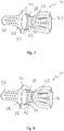
- the 7 and 8 show modified configurations of the mixer 12.
- integrally molded deflection elements 60, 62 are provided on the reagent passage body region 24 on both sides of the reagent passage opening 26 formed therein. These are shaped such that they converge towards one another in the main reagent delivery direction R and thus an increased flow deflection can act in the direction of the deflection back region 40 of the mixer main body region 36.
- more than two deflection elements of this type can be provided here in succession, which can be provided, for example, by bending corresponding tabs left on the inner circumference of the reaction medium passage opening 26.
- the deflection elements 60, 62 are shaped such that they first constrict the flow cross-section converging towards one another and then provide for a widening of the flow cross-section by means of a divergent arrangement. Because of the Venturi effect which is brought about in this way, an acceleration of the flow of reactant and also exhaust gas passing through the reactant passage opening 26 is achieved.
- a funnel-like deflection formation can also be provided by pulling the mixer body 22 in the reactant passage body region 24 and thereby molding this formation.
Landscapes
- Chemical & Material Sciences (AREA)
- Chemical Kinetics & Catalysis (AREA)
- Engineering & Computer Science (AREA)
- Health & Medical Sciences (AREA)
- Toxicology (AREA)
- Combustion & Propulsion (AREA)
- Mechanical Engineering (AREA)
- General Engineering & Computer Science (AREA)
- Dispersion Chemistry (AREA)
- Exhaust Gas After Treatment (AREA)
- Exhaust Gas Treatment By Means Of Catalyst (AREA)
Abstract
Description
- Die vorliegende Erfindung betrifft einen Mischer, der in einer Abgasanlage einer Brennkraftmaschine dazu eingesetzt werden kann, eine verbesserte Durchmischung von in den Abgasstrom eingespritztem Reaktionsmittel herbeizuführen.
- Ein derartiger aus der deutschen Patentanmeldung
10 2016 104 361 bekannter Mischer weist eine im Wesentlichen scheibenartige Gestalt auf und ist aus zwei mit näherungsweise kreisrunder Umfangskontur aufgebauten Scheibenteilen zusammengesetzt. Die Scheibenteile sind so geformt, dass sie einen Kanal zur Aufnahme von Reaktionsmittel bereitstellen. In diesen Kanal kann den Mischer umströmendes Abgas eintreten und sich somit mit dem eingespritzten Reaktionsmittel, beispielsweise einer Harnstoff/Wasser-Lösung, vermischen. Von diesem Kanal zweigen zwischen den beiden Scheibenteilen gebildete Abgabekanäle ab, über welche das Gemisch aus Reaktionsmittel und Abgas in den stromabwärts folgenden Teil einer Abgasanlage strömen kann. - Es ist die Aufgabe der vorliegenden Erfindung, einen Mischer für eine Abgasanlage zur Durchmischung von in einen Abgasstrom eingespritztem Reaktionsmittel mit Abgas vorzusehen, welcher bei baulich einfacher Ausgestaltung eine effiziente Durchmischung bewirken kann.
- Erfindungsgemäß wird diese Aufgabe gelöst durch einen Mischer für eine Abgasanlage zur Durchmischung von in einen Abgasstrom eingespritztem Reaktionsmittel mit Abgas, umfassend einen Mischerkörper mit einem Reaktionsmitteldurchtrittskörperbereich mit einer Reaktionsmitteldurchtrittsöffnung, einem in einer Mischerlängsrichtung an einer Seite an den Reaktionsmitteldurchtrittskörperbereich angrenzenden Mischerplattenkörperbereich und einem in der Mischerlängsrichtung an einer der einen Seite entgegengesetzten anderen Seite an den Reaktionsmitteldurchtrittskörperbereich angrenzenden Mischerhauptkörperbereich.
- Mit diesem Aufbau eines Mischers wird es möglich, diesen als ein Materialstück bereitzustellen und durch entsprechende Formgebung die verschiedenen Funktionsbereiche daran bereitzustellen.
- Beispielsweise kann der Aufbau derart sein, dass der Mischerkörper im Reaktionsmitteldurchtrittskörperbereich oder/und im Mischerplattenkörperbereich im Wesentlichen ungekrümmt ist.
- Für die Integration eines erfindungsgemäß aufgebauten Mischers in ein Abgasrohr kann beispielsweise vorgesehen sein, dass der Mischerplattenkörperbereich bezüglich des Reaktionsmitteldurchtrittskörperbereichs in einem ersten Anwinkelungsbereich in einer ersten Anwinkelungsrichtung angewinkelt ist, oder/und dass der Mischerhauptkörperbereich in einem zweiten Anwinkelungsbereich bezüglich des Reaktionsmitteldurchtrittskörperbereichs in einer zweiten Anwinkelungsrichtung angewinkelt ist, wobei vorzugsweise die erste Anwinkelungsrichtung der zweiten Anwinkelungsrichtung entgegengesetzt ist oder/und im zweiten Anwinkelungsbereich eine Mehrzahl von Durchtrittsöffnungen vorgesehen ist.
- Um für eine definierte Durchmischung von Reaktionsmittel und Abgas eine entsprechende Ausrichtung des Mischerhauptkörperbereichs bezüglich des Reaktionsmitteldurchtrittskörperbereichs erreichen zu können, wird vorgeschlagen, dass im zweiten Anwinkelungsbereich der Mischerhauptkörperbereich bezüglich des Reaktionsmitteldurchtrittskörperbereichs stärker angewinkelt ist als der Mischerplattenkörperbereich im ersten Anwinkelungsbereich bezüglich des Reaktionsmitteldurchtrittskörperbereichs angewinkelt ist.
- Für eine ausreichende Umströmung des Mischers mit Abgas kann der Mischerkörper im Reaktionsmitteldurchtrittskörperbereich quer zur Mischerlängsrichtung breiter sein als im Mischerplattenkörperbereich oder/und kann die im Reaktionsmitteldurchtrittskörperbereich vorgesehene Reaktionsmitteldurchtrittsöffnung quer zur Mischerlängsrichtung breiter sein als der Mischerplattenkörperbereich.
- Die Durchmischung von Abgas und Reaktionsmittel kann dadurch unterstützt werden, dass im Mischerplattenkörperbereich eine Mehrzahl von Durchtrittsöffnungen vorgesehen ist.
- Um das in Richtung auf den Mischerhauptkörperbereich zu strömende Reaktionsmittel effizient mit dem den Mischer umströmenden Abgas zu durchmischen, wird vorgeschlagen, dass der Mischerkörper im Mischerhauptkörperbereich einen der Reaktionsmitteldurchtrittsöffnung zugewandt liegenden Ablenkrückenbereich und quer zur Mischerlängsrichtung beidseits des Ablenkrückenbereichs jeweils einen ausgehend vom Ablenkrückenbereich in Richtung von der Reaktionsmitteldurchtrittsöffnung weg sich erstreckenden Mischflächenbereich aufweist.
- Um dabei eine hohe Wirksamkeit der Mischflächenbereiche zu erreichen, kann vorgesehen sein, dass die beiden Mischflächenbereiche ausgehend vom Ablenkrückenbereich quer zur Mischerlängsrichtung auseinanderlaufen, oder/und dass in den Mischflächenbereichen eine Mehrzahl von Durchtrittsöffnungen vorgesehen ist.
- Für eine baulich einfach zu realisierende Ausgestaltung kann der Ablenkrückenbereich ausgehend vom zweiten Anwinkelungsbereich sich in Richtung vom Reaktionsmitteldurchtrittskörperbereich weg erstrecken. Alternativ oder zusätzlich kann vorgesehen sein, dass der Ablenkrückenbereich ausgehend vom zweiten Anwinkelungsbereich sich in einem ersten Längenbereich im Wesentlichen geradlinig erstreckt und in einem an den ersten Längenbereich anschließenden und bezüglich diesem angewinkelten zweiten Längenbereich sich im Wesentlichen geradlinig erstreckt.
- Für eine verstärkte Durchmischung bei ausreichender Durchströmfläche wird vorgeschlagen, dass der Ablenkrückenbereich im zweiten Längenbereich eine Mehrzahl von Durchtrittsöffnungen aufweist, oder/und dass der Ablenkrückenbereich im ersten Längenbereich keine Durchtrittsöffnungen aufweist.
- Eine die Durchmischung von Reaktionsmittel und Abgas herbeiführende Verwirbelung des Abgasstroms kann beispielsweise dadurch erzeugt werden, dass der Mischerhauptkörperbereich an jeden Mischflächenbereich anschließend einen bezüglich diesem angewinkelten Ablenkflächenbereich aufweist.
- Dabei kann vorgesehen sein, dass die Ablenkflächenbereiche sich ausgehend vom Angrenzungsbereich des ersten Längenbereichs des Ablenkrückenbereichs an den zweiten Anwinkelungsbereich entlang der Mischflächenbereiche zu einem vom ersten Längenbereich entfernten Ende des zweiten Längenbereichs des Ablenkrückenbereichs erstrecken.
- Um eine definierte Strömung in Richtung auf den Mischerhauptkörperbereich zu zu unterstützen, wird vorgeschlagen, dass am Reaktionsmitteldurchtrittskörperbereich die Reaktionsmitteldurchtrittsöffnung umgebend eine in Richtung auf den Mischerhauptkörperbereich zu sich erstreckende Strömungsführungselementenformation vorgesehen ist.
- Aufgrund der baulich einfachen Ausgestaltung ist es möglich, den Mischerkörper einstückig auszubilden oder/und aus einem Blechteil aufzubauen.
- Die vorliegende Erfindung betrifft ferner eine Abgasanlage für eine Brennkraftmaschine, umfassend ein Abgasrohr, eine Reaktionsmittel in einer Reaktionsmittel-Hauptabgaberichtung in das Abgasrohr abgebende Reaktionsmittelabgabeanordnung und einen erfindungsgemäß aufgebauten Mischer.
- Um eine effiziente Durchmischung des Reaktionsmittels mit dem Abgas herbeizuführen, wird vorgeschlagen, dass der Mischer derart im Abgasrohr angeordnet ist, dass die Reaktionsmittel-Hauptabgaberichtung durch die Reaktionsmitteldurchtrittsöffnung hindurch auf den Mischerhauptkörperbereich zu gerichtet ist.
- Der Mischerplattenkörperbereich kann in einer Abgas-Hauptströmungsrichtung im Abgasrohr stromaufwärts bezüglich des Reaktionsmitteldurchtrittskörperbereichs angeordnet sein. Ferner kann der Mischerhauptkörperbereich im Wesentlichen orthogonal zur Abgas-Hauptströmungsrichtung im Abgasrohr angeordnet sein.
- Die vorliegende Erfindung wird nachfolgend mit Bezug auf die beiliegenden Figuren detailliert beschrieben. Es zeigt:
- Fig. 1
- eine Längsschnittansicht einer Abgasanlage mit einer Reaktionsmittelabgabeanordnung und einem Mischer;
- Fig. 2
- eine perspektivische Ansicht des Mischers der Abgasanlage der
Fig. 1 ; - Fig. 3
- eine Ansicht des Mischers der
Fig. 2 in Blickrichtung III inFig. 1 ; - Fig. 4
- eine Ansicht des Mischers der
Fig. 2 in Blickrichtung IV inFig. 1 ; - Fig. 5
- eine Ansicht des Mischers der
Fig. 2 in Blickrichtung V inFig. 1 ; - Fig. 6
- eine Ansicht des Mischers der
Fig. 2 in Blickrichtung VI inFig. 1 ; - Fig. 7
- eine der
Fig. 3 entsprechende Ansicht einer alternativen Ausgestaltungsart des Mischers; - Fig. 8
- eine weitere der
Fig. 3 entsprechende Ansicht einer alternativen Ausgestaltungsart des Mischers. - Die
Fig. 1 zeigt in Längsschnittansicht einen Abschnitt einer allgemein mit 10 bezeichneten Abgasanlage für eine Brennkraftmaschine eines Fahrzeugs. Diese Abgasanlage 10 umfasst ein Abgasrohr 12, in welchen das von einer Brennkraftmaschine ausgestoßene Abgas in einer Abgas-Hauptströmungsrichtung A strömt. In einem seitlichen Ausbauchungsbereich 14 ist am Abgasrohr 12 eine allgemein auch als Injektor bezeichnete Reaktionsmittelabgabeanordnung 16 derart vorgesehen, dass diese das in das Abgas einzuspritzende Abgas in Form eines Sprühkegels 18 in einer Reaktionsmittel-Hauptabgaberichtung R in den Abgasstrom einspritzt. Aufgrund des Umstandes, dass die Reaktionsmittelabgabeanordnung 16 im seitlichen Ausbauchungsbereich 14 an das Abgasrohr 12 angebunden ist, sind die Abgas-Hauptströmungsrichtung A und die Reaktionsmittel-Hauptabgaberichtung R nicht parallel zueinander, sondern schließen einen Winkel im Bereich von etwa 45° zueinander ein. - Im Abgasrohr 12 ist ferner ein allgemein mit 20 bezeichneter und nachfolgend auch mit Bezug auf die
Fig. 2 bis 6 detailliert beschriebener Mischer vorgesehen. Der Mischer 20 dient dazu, eine verbesserte Durchmischung von im Abgasrohr 12 strömendem Abgas mit in den Abgasstrom eingespritztem Reaktionsmittel, also beispielsweise einer Harnstoff/Wasser-Lösung, zu erreichen, so dass in einer stromabwärts folgenden SCR-Katalysatoranordnung auch eine effiziente Abgasreinigung bewirkt werden kann. - Der Mischer 20 umfasst einen vorzugsweise aus einem einzigen Blechstück geformten Mischerkörper 22. Dazu kann aus einer Blechplatte in Rohling für den Mischerkörper 22 herausgetrennt, mit den verschiedenen nachfolgend noch erläuterten Öffnungen versehen und dann durch einen Umformungsprozess in die nachfolgend noch erläuterte Form gebracht werden.
- Der Mischerkörper 22 umfasst als zentralen Bereich einen Reaktionsmitteldurchtrittskörperbereich 24. Dieser im Wesentlichen eben, also ungekrümmt ausgebildete Reaktionsmitteldurchtrittskörperbereich 24 stellt eine beispielsweise mit kreisrunder oder eckiger Kontur ausgebildete Reaktionsmitteldurchtrittsöffnung 26 bereit. An einer Seite des Reaktionsmitteldurchtrittskörperbereichs 24 in einer Mischerlängsrichtung L schließt in einem ersten Anwinkelungsbereich 28 ein beispielsweise ebenfalls im Wesentlichen eben, also ungekrümmt ausgebildeter Mischerplattenkörperbereich 30 an. Im Mischerplattenkörperbereich 30 sind mehrere Durchtrittsöffnungen 32, beispielsweise in drei Reihen angeordnet, vorgesehen. An der anderen Seite des Reaktionsmitteldurchtrittskörperbereichs 24 in der Mischerlängsrichtung L schließt in einem zweiten Anwinkelungsbereich 34 ein allgemein mit 36 bezeichneter Mischerhauptkörperbereich an. Die
Fig. 1 und 2 zeigen deutlich, dass in den beiden Anwinkelungsbereichen 28, 34 der Mischerkörper 22 in entgegengesetzten Richtungen angewinkelt ist. Weiter ist deutlich erkennbar, dass im ersten Anwinkelungsbereich 28 der Mischerplattenkörperbereich 30 in geringerem Ausmaß bezüglich des Reaktionsmitteldurchtrittskörperbereichs 224 angewinkelt ist, als der Mischerhauptkörperbereich 36 im zweiten Anwinkelungsbereich 34 bezüglich des Reaktionsmitteldurchtrittskörperbereichs 24 angewinkelt ist. Während beispielsweise die Anwinkelung im ersten Anwinkelungsbereich 28 kleiner als 45° sein kann, ist die in entgegengesetzter Richtung vorgesehene Anwinkelung im zweiten Anwinkelungsbereich 34 im Bereich von 90° oder mehr. - Die
Fig. 3 und 4 zeigen deutlich, dass die Breite d des Mischerplattenkörperbereichs 30 quer zur Mischerlängsrichtung L kleiner ist, als die quer zur Mischerlängsrichtung L gemessene Breite D der Reaktionsmitteldurchtrittsöffnung 26. Auf diese Art und Weise überdeckt der Mischerplattenkörperbereich 30 bei der inFig. 1 dargestellten Positionierung des Mischers 20 im Abgasrohr 12 die in Strömungsrichtung folgenden Bereiche nur teilweise bzw. schirmt dieser nur teilweise gegen die Anströmung mit Abgas ab. - Der Mischerhauptkörperbereich 36 ist derart geformt, dass er, ausgehend vom zweiten Anwinkelungsbereich 34, in welchem ebenfalls Durchtrittsöffnungen 38 vorgesehen sein können, einen in Richtung zur Reaktionsmitteldurchtrittsöffnung 26 bzw. zum Reaktionsmitteldurchtrittskörperbereich 24 orientierten Ablenkrückenbereich 40 aufweist. Der Ablenkrückenbereich 40 weist einen ausgehend vom zweiten Abwinkelungsbereich 32 sich im Wesentlichen geradlinig erstreckenden ersten Längenbereich 42 und anschließend an den ersten Längenbereich 42 einen sich im Wesentlichen geradlinig erstreckenden zweiten Längenbereich 44 auf. Während beispielsweise im ersten Längenbereich 42 des Ablenkrückenbereichs 40 keine Durchtrittsöffnungen vorgesehen sein können, sind im zweiten Längenbereich 44 mehrere Durchtrittsöffnungen 46 vorgesehen.
- An den ersten Ablenkrückenbereich 42 schließen quer zur Mischerlängsrichtung L beidseits Mischflächenbereiche 48, 50 an. Diese erstrecken sich ausgehend vom Ablenkrückenbereich 40 in Richtung vom Reaktionsmitteldurchtrittskörperbereich 24 weg und quer zur Mischerlängsrichtung L voneinander weg, so dass der Mischerhauptkörperbereich 36 in der Mischerlängsrichtung L betrachtet in Strömungsrichtung eine zunehmende Breite aufweist. In jedem der Mischflächenbereiche 48, 50 sind wiederum mehrere Durchtrittsöffnungen 52, 54 vorgesehen.
- Angrenzend an jeden Mischflächenbereich 48, 50 ist ein bezüglich des jeweils zugeordneten Mischflächenbereichs 48 bzw. 50 angewinkelter, also im Wesentlichen quer zur Mischerlängsrichtung L von diesem sich weg erstreckender Ablenkflächenbereich 56, 58 vorgesehen. Die Ablenkflächenbereiche 56, 58 erstrecken sich ausgehend von dem Bereich, in welchem der Ablenkrückenbereich 40 an den zweiten Anwinkelungsbereich 34 angrenzt, entlang der Mischflächenbereiche 48, 50 bis zu einem vom ersten Längenbereich 42 des Ablenkrückenbereichs 40 entfernten Ende des zweiten Längenbereichs 44 des Ablenkrückenbereichs 40. Damit weisen die Ablenkflächenbereiche 56, 58 eine an die Formgebung der Mischflächenbereichen 48, 50 angepasste gekrümmte Kontur auf.
- Der Mischer 20 wird derart in das Abgasrohr 11 eingesetzt, dass der Mischerplattenkörperbereich 30 in seinem vom Reaktionsmitteldurchtrittskörperbereich 24 entfernten Ende an der Innenseite des Abgasrohrs 12 stromaufwärts der Ausbauchung 40 bzw. der Positionierung der Reaktionsmitteleingabeanordnung 16 anliegt und dort beispielsweise durch Verschweißung oder dergleichen festgelegt ist. Der Mischerhauptkörperbereich 36 liegt mit seinem vom zweiten Anwinkelungsbereich 34 entfernten Ende an einer gegenüberliegenden Seite des Abgasrohrs 12 an dessen Innenoberfläche an und ist dort beispielsweise ebenfalls durch Verschweißung festgelegt. Der Reaktionsmitteldurchtrittskörperbereich 24 ist mit seiner Reaktionsmitteldurchtrittsöffnung 26 so positioniert bzw. orientiert, dass er bereichsweise in die Ausbauchung 14 eingreifend einen Hindurchtritt des in Form des Sprühkegels 18 abgegebenen Reaktionsmittels in Richtung zum Ablenkrückenbereich 40 des Reaktionsmittelhauptkörperbereichs 36 zulässt. Quer zur Mischerlängsrichtung L ist der Reaktionsmitteldurchtrittskörperbereich 24 so dimensioniert, dass er beidseits der Reaktionsmitteldurchtrittsöffnung 26 mit seitlichen Randbereichen an der Innenoberfläche des Abgasrohrs 12 anliegt und dort beispielsweise durch Verschweißen am Abgasrohr 12 festgelegt ist.
- Bereits im Bereich vor dem Hindurchtritt durch die Reaktionsmitteldurchtrittsöffnung 26 kann den Mischerplattenkörperbereich 30 im Bereich der Durchtrittsöffnungen 32 durchströmendes bzw. seitlich an diesem vorbeiströmendes Abgas in den Bereich des Sprühkegels 18 strömen und dort eine Durchmischung mit dem Reaktionsmittel herbeiführen. Der auf den Ablenkrückenbereich 40 auftreffende Reaktionsmittelstrom wird durch die in Richtung stromaufwärts konvex gewölbte Struktur des Reaktionsmittelhauptkörperbereichs 36 geteilt und entlang der beiden Mischflächenbereiche 48, 50 in Richtung auf die Ablenkflächenbereiche 56, 58 zu geleitet. Dabei wird eine Verwirbelung erzeugt, welche eine effiziente Durchmischung des Reaktionsmittels mit dem auch in der Abgas-Hauptströmungsrichtung A auf den Mischerhauptkörperbereich 36 zu strömenden Abgas bewirkt. Dabei kann bereits ein Teil des mit Reaktionsmittel durchmischten Abgases durch die Durchtrittsöffnungen 38, 52, 54 und 46 hindurchströmen. Ein weiterer Teil des Gemisches aus Abgas und Reaktionsmittel kann, nach seitlich außen abgelenkt durch die Ablenkflächenbereiche 56, 58 den Mischerhauptkörperbereich 36 umströmen und in den stromabwärts dann folgenden Bereich des Abgasrohrs 12 in Richtung auf eine SCR-Katalysatoranordnung zu strömen.
- Die vorangehend beschriebene vergleichsweise schmale Ausgestaltung des Mischerplattenkörperbereichs 30 im Vergleich zum Reaktionsmitteldurchtrittskörperbereich 24 und die dadurch ermöglichte Anströmung des Reaktionsmitteldurchtrittskörperbereichs 24 mit Abgas an beiden Seiten desselben ermöglicht eine effiziente Erwärmung des gesamten Mischerkörpers 22, so dass auch eine verstärkte Abdampfung des auf dessen Oberfläche auftreffenden Reaktionsmittels bewirkt werden kann. Ein Teil des Abgasstroms kann dabei den Mischerkörper 22 im Bereich des zweiten Anwinkelungsbereichs 34 außen umströmen, also zwischen diesem und dem Abgasrohr 12 hindurchströmen, so dass ein nur mit einem geringen Anteil an Reaktionsmittel durchsetzter Abgasstrom auf die stromabwärtige Seite des Mischerhauptkörperbereichs 36 gelangen wird und dort aufgrund der vermittels der Ablenkflächenbereiche 56, 58 erzeugten Verwirbelung zu einer effizienten Durchmischung des aus dem Bereich des Mischerhauptkörperbereichs 36 heranströmenden mit Reaktionsmittel hoch konzentrierten Abgasstroms führen wird.
- Die
Fig. 7 und 8 zeigen abgewandelt Ausgestaltungen des Mischers 12. Man erkennt inFig. 7 , dass am Reaktionsmitteldurchtrittskörperbereich 24 beidseits der darin gebildeten Reaktionsmitteldurchtrittsöffnung 26 beispielsweise integral angeformte Ablenkelemente 60, 62 vorgesehen sind. Diese sind so geformt, dass sie in der Reaktionsmittel-Hauptabgaberichtung R aufeinander zu konvergieren und somit eine verstärkte Strömungsablenkung in Richtung auf den Ablenkrückenbereich 40 des Mischerhauptkörperbereichs 36 wirken können. Es ist selbstverständlich, dass hier mehr als zwei derartige Ablenkelemente aufeinander folgend vorgesehen sein können, die beispielsweise durch Umbiegen entsprechender am Innenumfang der Reaktionsmitteldurchtrittsöffnung 26 belassener Laschen bereitgestellt werden können. - Bei der in
Fig. 8 dargestellten Ausgestaltung sind die Ablenkelemente 60, 62 derart geformt, dass sie zunächst aufeinander zu konvergierend den Durchströmquerschnitt einschnüren und dann durch divergierende Anordnung eine Aufweitung des Durchströmquerschnitts vorsehen. Aufgrund des so herbeigeführten Venturi-Effekts wird eine Beschleunigung des durch die Reaktionsmitteldurchtrittsöffnung 26 hindurchtretenden Stroms von Reaktionsmittel und auch Abgas erreicht. - Auch eine trichterartige Ablenkformation kann durch Ziehen des Mischerkörpers 22 im Reaktionsmitteldurchtrittskörperbereich 24 und dabei Anformen dieser Formation bereitgestellt werden.
Claims (15)
- Mischer für eine Abgasanlage zur Durchmischung von in einen Abgasstrom eingespritztem Reaktionsmittel mit Abgas, umfassend einen Mischerkörper (22) mit einem Reaktionsmitteldurchtrittskörperbereich (24) mit einer Reaktionsmitteldurchtrittsöffnung (26), einem in einer Mischerlängsrichtung (L) an einer Seite an den Reaktionsmitteldurchtrittskörperbereich (24) angrenzenden Mischerplattenkörperbereich (30) und einem in der Mischerlängsrichtung (L) an einer der einen Seite entgegengesetzten anderen Seite an den Reaktionsmitteldurchtrittskörperbereich (24) angrenzenden Mischerhauptkörperbereich (36).
- Mischer nach Anspruch 1, dadurch gekennzeichnet, dass der Mischerkörper (22) im Reaktionsmitteldurchtrittskörperbereich (24) oder/und im Mischerplattenkörperbereich (30) im Wesentlichen ungekrümmt ist.
- Mischer nach Anspruch 1 oder 2, dadurch gekennzeichnet, dass der Mischerplattenkörperbereich (30) bezüglich des Reaktionsmitteldurchtrittskörperbereichs (24) in einem ersten Anwinkelungsbereich (28) in einer ersten Anwinkelungsrichtung angewinkelt ist, oder/und dass der Mischerhauptkörperbereich (36) in einem zweiten Anwinkelungsbereich (34) bezüglich des Reaktionsmitteldurchtrittskörperbereichs (24) in einer zweiten Anwinkelungsrichtung angewinkelt ist.
- Mischer nach Anspruch 3, dadurch gekennzeichnet,
dass die erste Anwinkelungsrichtung der zweiten Anwinkelungsrichtung entgegengesetzt ist, oder/und dass im zweiten Anwinkelungsbereich (34) eine Mehrzahl von Durchtrittsöffnungen (38) vorgesehen ist,
oder/und
dass im zweiten Anwinkelungsbereich (32) der Mischerhauptkörperbereich (36) bezüglich des Reaktionsmitteldurchtrittskörperbereichs (24) stärker angewinkelt ist als der Mischerplattenkörperbereich (30) im ersten Anwinkelungsbereich (28) bezüglich des Reaktionsmitteldurchtrittskörperbereichs (24) angewinkelt ist. - Mischer nach einem der vorangehenden Ansprüche, dadurch gekennzeichnet, dass der Mischerkörper (22) im Reaktionsmitteldurchtrittskörperbereich (24) quer zur Mischerlängsrichtung (L) breiter ist als im Mischerplattenkörperbereich (30), oder/und dass die im Reaktionsmitteldurchtrittskörperbereich (24) vorgesehene Reaktionsmitteldurchtrittsöffnung (26) quer zur Mischerlängsrichtung (L) breiter ist als der Mischerplattenkörperbereich (30).
- Mischer nach einem der vorangehenden Ansprüche, dadurch gekennzeichnet, dass im Mischerplattenkörperbereich (30) eine Mehrzahl von Durchtrittsöffnungen (32) vorgesehen ist,
oder/und
dass der Mischerkörper (22) im Mischerhauptkörperbereich (36) einen der Reaktionsmitteldurchtrittsöffnung (26) zugewandt liegenden Ablenkrückenbereich (40) und quer zur Mischerlängsrichtung (L) beidseits des Ablenkrückenbereichs (40) jeweils einen ausgehend vom Ablenkrückenbereich (40) in Richtung von der Reaktionsmitteldurchtrittsöffnung (36) weg sich erstreckenden Mischflächenbereich (48, 50) aufweist. - Mischer nach Anspruch 6, dadurch gekennzeichnet, dass die beiden Mischflächenbereiche (48, 50) ausgehend vom Ablenkrückenbereich (40) quer zur Mischerlängsrichtung (L) auseinanderlaufen, oder/und dass in den Mischflächenbereichen (48, 50) eine Mehrzahl von Durchtrittsöffnungen (52, 54) vorgesehen ist.
- Mischer nach Anspruch 3 und Anspruch 6 oder 7, dadurch gekennzeichnet, dass der Ablenkrückenbereich (40) ausgehend vom zweiten Anwinkelungsbereich (34) sich in Richtung vom Reaktionsmitteldurchtrittskörperbereich (24) weg erstreckt, oder/und dass der Ablenkrückenbereich (40) ausgehend vom zweiten Anwinkelungsbereich (34) sich in einem ersten Längenbereich (42) im Wesentlichen geradlinig erstreckt und in einem an den ersten Längenbereich (42) anschließenden und bezüglich diesem angewinkelten zweiten Längenbereich (44) sich im Wesentlichen geradlinig erstreckt.
- Mischer nach Anspruch 8, dadurch gekennzeichnet, dass der Ablenkrückenbereich (40) im zweiten Längenbereich (44) eine Mehrzahl von Durchtrittsöffnungen (46) aufweist, oder/und dass der Ablenkrückenbereich (40) im ersten Längenbereich (42) keine Durchtrittsöffnungen aufweist.
- Mischer nach einem der Ansprüche 6-9, dadurch gekennzeichnet, dass der Mischerhauptkörperbereich (36) an jeden Mischflächenbereich (48, 50) anschließend einen bezüglich diesem angewinkelten Ablenkflächenbereich (56, 58) aufweist.
- Mischer nach Anspruch 8 und Anspruch 10, dadurch gekennzeichnet, dass die Ablenkflächenbereiche (56, 58) sich ausgehend vom Angrenzungsbereich des ersten Längenbereichs (42) des Ablenkrückenbereichs (40) an den zweiten Anwinkelungsbereich (34) entlang der Mischflächenbereiche (48, 50) zu einem vom ersten Längenbereich (42) entfernten Ende des zweiten Längenbereichs (44) des Ablenkrückenbereichs (40) erstrecken.
- Mischer nach einem der vorangehenden Ansprüche, dadurch gekennzeichnet, dass am Reaktionsmitteldurchtrittskörperbereich (24) die Reaktionsmitteldurchtrittsöffnung (26) umgebend eine in Richtung auf den Mischerhauptkörperbereich (36) zu sich erstreckende Strömungsführungselementenformation (60, 62) vorgesehen ist,
oder/und
dass der Mischerkörper (22) einstückig ausgebildet ist, oder/und dass der Mischerkörper (22) aus einem Blechteil aufgebaut ist. - Abgasanlage für eine Brennkraftmaschine, umfassend ein Abgasrohr (12), eine Reaktionsmittel in einer Reaktionsmittel-Hauptabgaberichtung (R) in das Abgasrohr (12) abgebende Reaktionsmittelabgabeanordnung (16) und einen Mischer (20) nach einem der vorangehenden Ansprüche.
- Abgasanlage nach Anspruch 13, dadurch gekennzeichnet, dass der Mischer (20) derart im Abgasrohr (12) angeordnet ist, dass die Reaktionsmittel-Hauptabgaberichtung (R) durch die Reaktionsmitteldurchtrittsöffnung (26) hindurch auf den Mischerhauptkörperbereich (36) zu gerichtet ist.
- Abgasanlage nach Anspruch 13 oder 14, dadurch gekennzeichnet, dass der Mischerplattenkörperbereich (30) in einer Abgas-Hauptströmungsrichtung (A) im Abgasrohr (12) stromaufwärts bezüglich des Reaktionsmitteldurchtrittskörperbereichs (24) angeordnet ist, oder/und dass der Mischerhauptkörperbereich (36) im Wesentlichen orthogonal zur Abgas-Hauptströmungsrichtung (A) im Abgasrohr (12) angeordnet ist.
Applications Claiming Priority (1)
| Application Number | Priority Date | Filing Date | Title |
|---|---|---|---|
| DE102018119578.8A DE102018119578A1 (de) | 2018-08-13 | 2018-08-13 | Mischer |
Publications (2)
| Publication Number | Publication Date |
|---|---|
| EP3611354A1 true EP3611354A1 (de) | 2020-02-19 |
| EP3611354B1 EP3611354B1 (de) | 2022-01-26 |
Family
ID=67551143
Family Applications (1)
| Application Number | Title | Priority Date | Filing Date |
|---|---|---|---|
| EP19190234.5A Active EP3611354B1 (de) | 2018-08-13 | 2019-08-06 | Mischer |
Country Status (4)
| Country | Link |
|---|---|
| US (1) | US11161080B2 (de) |
| EP (1) | EP3611354B1 (de) |
| CN (1) | CN110821617B (de) |
| DE (1) | DE102018119578A1 (de) |
Families Citing this family (4)
| Publication number | Priority date | Publication date | Assignee | Title |
|---|---|---|---|---|
| JP2021156226A (ja) * | 2020-03-27 | 2021-10-07 | フタバ産業株式会社 | 排ガス浄化装置 |
| US12228061B2 (en) * | 2021-06-30 | 2025-02-18 | Cummins Emission Solutions Inc. | Decomposition chamber with guide swirl mixer |
| DE102021006331A1 (de) * | 2021-12-23 | 2023-06-29 | Daimler Truck AG | Kammermischer für ein Abgasnachbehandlungssystem eines Kraftfahrzeugs |
| JP2025171357A (ja) * | 2024-05-09 | 2025-11-20 | いすゞ自動車株式会社 | 排気処理装置 |
Citations (5)
| Publication number | Priority date | Publication date | Assignee | Title |
|---|---|---|---|---|
| US20110094206A1 (en) * | 2009-10-27 | 2011-04-28 | Cummins Filtration Ip, Inc | Reductant injection and decomposition system |
| WO2012089290A1 (de) * | 2010-12-27 | 2012-07-05 | Friedrich Boysen Gmbh & Co. Kg | Vorrichtung zum verteilen von fluiden in abgasanlagen |
| GB2512934A (en) * | 2013-04-12 | 2014-10-15 | Eminox Ltd | Reductant injection in an exhaust system |
| US20160319723A1 (en) * | 2015-04-30 | 2016-11-03 | Faurecia Emissions Control Technologies, Usa, Llc | Mixer with integrated doser cone |
| EP3216992A1 (de) * | 2016-03-10 | 2017-09-13 | Eberspächer Exhaust Technology GmbH & Co. KG | Mischer |
Family Cites Families (13)
| Publication number | Priority date | Publication date | Assignee | Title |
|---|---|---|---|---|
| JPH03206314A (ja) * | 1990-01-08 | 1991-09-09 | Yanmar Diesel Engine Co Ltd | ディーゼルエンジンのアンモニア脱硝システムにおける還元剤水溶液注入ノズル装置 |
| JP4600457B2 (ja) * | 2007-10-02 | 2010-12-15 | トヨタ自動車株式会社 | 排気通路の添加剤分散板構造 |
| US8033104B2 (en) * | 2008-07-09 | 2011-10-11 | Ford Global Technologies, Llc | Selective catalytic reduction (SCR) catalyst injection systems |
| US9429058B2 (en) * | 2008-12-01 | 2016-08-30 | GM Global Technology Operations LLC | Mixing devices for selective catalytic reduction systems |
| DE102013223033A1 (de) * | 2013-11-12 | 2015-05-13 | Eberspächer Exhaust Technology GmbH & Co. KG | Katalysatoranordnung mit Injektionsabschnitt |
| DE102014205158A1 (de) * | 2014-03-19 | 2015-09-24 | Eberspächer Exhaust Technology GmbH & Co. KG | Mischer für eine Abgasanlage |
| US20140286832A1 (en) * | 2014-06-06 | 2014-09-25 | Caterpillar Inc. | Exhaust system |
| DE102016117746A1 (de) * | 2016-09-21 | 2018-03-22 | Eberspächer Exhaust Technology GmbH & Co. KG | Reaktionsmitteleingabeanordnung zur Eingabe von Reaktionsmittel in den Abgasstrom einer Brennkraftmaschine |
| EP3321484B1 (de) * | 2016-11-14 | 2021-04-07 | Eberspächer Exhaust Technology GmbH & Co. KG | Reaktionsmittelabgabeanordnung |
| EP3379046B1 (de) * | 2017-03-24 | 2020-09-09 | Volvo Car Corporation | Abgasnachbehandlungssystem |
| US10605143B2 (en) * | 2017-07-14 | 2020-03-31 | Ford Global Technologies, Llc | Exhaust gas mixer |
| CN108915831B (zh) * | 2017-09-19 | 2021-04-02 | 天纳克(苏州)排放系统有限公司 | 尾气后处理混合装置 |
| US10767537B1 (en) * | 2019-06-28 | 2020-09-08 | GM Global Technology Operations LLC | Hydrocarbon injector deflector assembly for diesel exhaust system |
-
2018
- 2018-08-13 DE DE102018119578.8A patent/DE102018119578A1/de not_active Withdrawn
-
2019
- 2019-08-06 EP EP19190234.5A patent/EP3611354B1/de active Active
- 2019-08-06 CN CN201910719244.8A patent/CN110821617B/zh active Active
- 2019-08-12 US US16/538,058 patent/US11161080B2/en active Active
Patent Citations (6)
| Publication number | Priority date | Publication date | Assignee | Title |
|---|---|---|---|---|
| US20110094206A1 (en) * | 2009-10-27 | 2011-04-28 | Cummins Filtration Ip, Inc | Reductant injection and decomposition system |
| WO2012089290A1 (de) * | 2010-12-27 | 2012-07-05 | Friedrich Boysen Gmbh & Co. Kg | Vorrichtung zum verteilen von fluiden in abgasanlagen |
| GB2512934A (en) * | 2013-04-12 | 2014-10-15 | Eminox Ltd | Reductant injection in an exhaust system |
| US20160319723A1 (en) * | 2015-04-30 | 2016-11-03 | Faurecia Emissions Control Technologies, Usa, Llc | Mixer with integrated doser cone |
| EP3216992A1 (de) * | 2016-03-10 | 2017-09-13 | Eberspächer Exhaust Technology GmbH & Co. KG | Mischer |
| DE102016104361A1 (de) | 2016-03-10 | 2017-09-14 | Eberspächer Exhaust Technology GmbH & Co. KG | Mischer |
Also Published As
| Publication number | Publication date |
|---|---|
| CN110821617A (zh) | 2020-02-21 |
| US20200047136A1 (en) | 2020-02-13 |
| DE102018119578A1 (de) | 2020-02-13 |
| US11161080B2 (en) | 2021-11-02 |
| EP3611354B1 (de) | 2022-01-26 |
| CN110821617B (zh) | 2022-06-07 |
Similar Documents
| Publication | Publication Date | Title |
|---|---|---|
| EP3216992B2 (de) | Mischer | |
| DE112014003949B4 (de) | Abgasreinigungsvorrichtung für Verbrennungsmotor | |
| DE112010002589B4 (de) | Abgasstrang mit Einspritzsystem | |
| EP2097625B1 (de) | Mischelement sowie abgasanlage für eine verbrennungskraftmaschine | |
| DE102010009043B4 (de) | Statischer Mischer für eine Abgasanlage einer Brennkraftmaschine | |
| EP3611354B1 (de) | Mischer | |
| DE202015102092U1 (de) | Abgasreinigungsbaugruppe | |
| DE112017003665T5 (de) | Strömungsumlenker zur minderung von ablagerungen in einem dosiererkegel | |
| DE102022112337A1 (de) | Mischerbaugruppe für ein fahrzeugabgassystem | |
| DE102016222743A1 (de) | Integriertes Abgasnachbehandlungssystem | |
| DE102015106876A1 (de) | Abgasreinigungsbaugruppe und Abgasleitung mit einer solchen Baugruppe | |
| DE112017007089T5 (de) | Abgasnachbehandlungseinrichtung | |
| DE102011108237A1 (de) | Anordnung zum Einbringen eines Zusatzstoffes in einen Gasstrom | |
| DE112021001259T5 (de) | Mischer zur Verwendung in Nachbehandlungssystemen | |
| DE102008029110A1 (de) | Misch- und/oder Verdampfungseinrichtung | |
| EP3071807A1 (de) | Abgasnachbehandlungseinrichtung | |
| DE102007002981B4 (de) | Statischer Mischer für eine Abgasanlage eines brennkraftmaschinenbetriebenen Fahrzeugs, insbesondere Kraftfahrzeugs | |
| DE102019117459A1 (de) | Mischer | |
| DE102018124025A1 (de) | Vorrichtung zum Zumischen eines flüssigen Reduktionsmittels zum Abgas einer Brennkraftmaschine und Kraftfahrzeug | |
| DE102019128193A1 (de) | Mischeranordnung | |
| EP3726017B1 (de) | Mischer | |
| EP3812557B1 (de) | Mischer | |
| AT517917B1 (de) | Mischeinrichtung für eine abgasnachbehandlungseinrichtung | |
| EP3686406B1 (de) | Mischer | |
| WO2021023418A1 (de) | Abgasnachbehandlungssystem für eine brennkraftmaschine eines kraftfahrzeugs |
Legal Events
| Date | Code | Title | Description |
|---|---|---|---|
| PUAI | Public reference made under article 153(3) epc to a published international application that has entered the european phase |
Free format text: ORIGINAL CODE: 0009012 |
|
| STAA | Information on the status of an ep patent application or granted ep patent |
Free format text: STATUS: THE APPLICATION HAS BEEN PUBLISHED |
|
| AK | Designated contracting states |
Kind code of ref document: A1 Designated state(s): AL AT BE BG CH CY CZ DE DK EE ES FI FR GB GR HR HU IE IS IT LI LT LU LV MC MK MT NL NO PL PT RO RS SE SI SK SM TR |
|
| AX | Request for extension of the european patent |
Extension state: BA ME |
|
| STAA | Information on the status of an ep patent application or granted ep patent |
Free format text: STATUS: REQUEST FOR EXAMINATION WAS MADE |
|
| STAA | Information on the status of an ep patent application or granted ep patent |
Free format text: STATUS: EXAMINATION IS IN PROGRESS |
|
| 17P | Request for examination filed |
Effective date: 20200818 |
|
| RBV | Designated contracting states (corrected) |
Designated state(s): AL AT BE BG CH CY CZ DE DK EE ES FI FR GB GR HR HU IE IS IT LI LT LU LV MC MK MT NL NO PL PT RO RS SE SI SK SM TR |
|
| 17Q | First examination report despatched |
Effective date: 20200917 |
|
| RAP1 | Party data changed (applicant data changed or rights of an application transferred) |
Owner name: PUREM GMBH |
|
| GRAP | Despatch of communication of intention to grant a patent |
Free format text: ORIGINAL CODE: EPIDOSNIGR1 |
|
| STAA | Information on the status of an ep patent application or granted ep patent |
Free format text: STATUS: GRANT OF PATENT IS INTENDED |
|
| RIC1 | Information provided on ipc code assigned before grant |
Ipc: B01F 5/06 20060101ALI20210907BHEP Ipc: B01F 5/02 20060101ALI20210907BHEP Ipc: B01F 3/04 20060101ALI20210907BHEP Ipc: B01F 5/00 20060101ALI20210907BHEP Ipc: F01N 3/28 20060101ALI20210907BHEP Ipc: F01N 3/20 20060101AFI20210907BHEP |
|
| INTG | Intention to grant announced |
Effective date: 20210929 |
|
| GRAS | Grant fee paid |
Free format text: ORIGINAL CODE: EPIDOSNIGR3 |
|
| GRAA | (expected) grant |
Free format text: ORIGINAL CODE: 0009210 |
|
| STAA | Information on the status of an ep patent application or granted ep patent |
Free format text: STATUS: THE PATENT HAS BEEN GRANTED |
|
| AK | Designated contracting states |
Kind code of ref document: B1 Designated state(s): AL AT BE BG CH CY CZ DE DK EE ES FI FR GB GR HR HU IE IS IT LI LT LU LV MC MK MT NL NO PL PT RO RS SE SI SK SM TR |
|
| REG | Reference to a national code |
Ref country code: GB Ref legal event code: FG4D Free format text: NOT ENGLISH |
|
| REG | Reference to a national code |
Ref country code: CH Ref legal event code: EP |
|
| REG | Reference to a national code |
Ref country code: AT Ref legal event code: REF Ref document number: 1465457 Country of ref document: AT Kind code of ref document: T Effective date: 20220215 |
|
| REG | Reference to a national code |
Ref country code: IE Ref legal event code: FG4D Free format text: LANGUAGE OF EP DOCUMENT: GERMAN |
|
| REG | Reference to a national code |
Ref country code: DE Ref legal event code: R096 Ref document number: 502019003306 Country of ref document: DE |
|
| REG | Reference to a national code |
Ref country code: LT Ref legal event code: MG9D |
|
| REG | Reference to a national code |
Ref country code: NL Ref legal event code: MP Effective date: 20220126 |
|
| PG25 | Lapsed in a contracting state [announced via postgrant information from national office to epo] |
Ref country code: NL Free format text: LAPSE BECAUSE OF FAILURE TO SUBMIT A TRANSLATION OF THE DESCRIPTION OR TO PAY THE FEE WITHIN THE PRESCRIBED TIME-LIMIT Effective date: 20220126 |
|
| PG25 | Lapsed in a contracting state [announced via postgrant information from national office to epo] |
Ref country code: SE Free format text: LAPSE BECAUSE OF FAILURE TO SUBMIT A TRANSLATION OF THE DESCRIPTION OR TO PAY THE FEE WITHIN THE PRESCRIBED TIME-LIMIT Effective date: 20220126 Ref country code: RS Free format text: LAPSE BECAUSE OF FAILURE TO SUBMIT A TRANSLATION OF THE DESCRIPTION OR TO PAY THE FEE WITHIN THE PRESCRIBED TIME-LIMIT Effective date: 20220126 Ref country code: PT Free format text: LAPSE BECAUSE OF FAILURE TO SUBMIT A TRANSLATION OF THE DESCRIPTION OR TO PAY THE FEE WITHIN THE PRESCRIBED TIME-LIMIT Effective date: 20220526 Ref country code: NO Free format text: LAPSE BECAUSE OF FAILURE TO SUBMIT A TRANSLATION OF THE DESCRIPTION OR TO PAY THE FEE WITHIN THE PRESCRIBED TIME-LIMIT Effective date: 20220426 Ref country code: LT Free format text: LAPSE BECAUSE OF FAILURE TO SUBMIT A TRANSLATION OF THE DESCRIPTION OR TO PAY THE FEE WITHIN THE PRESCRIBED TIME-LIMIT Effective date: 20220126 Ref country code: HR Free format text: LAPSE BECAUSE OF FAILURE TO SUBMIT A TRANSLATION OF THE DESCRIPTION OR TO PAY THE FEE WITHIN THE PRESCRIBED TIME-LIMIT Effective date: 20220126 Ref country code: ES Free format text: LAPSE BECAUSE OF FAILURE TO SUBMIT A TRANSLATION OF THE DESCRIPTION OR TO PAY THE FEE WITHIN THE PRESCRIBED TIME-LIMIT Effective date: 20220126 Ref country code: BG Free format text: LAPSE BECAUSE OF FAILURE TO SUBMIT A TRANSLATION OF THE DESCRIPTION OR TO PAY THE FEE WITHIN THE PRESCRIBED TIME-LIMIT Effective date: 20220426 |
|
| PG25 | Lapsed in a contracting state [announced via postgrant information from national office to epo] |
Ref country code: PL Free format text: LAPSE BECAUSE OF FAILURE TO SUBMIT A TRANSLATION OF THE DESCRIPTION OR TO PAY THE FEE WITHIN THE PRESCRIBED TIME-LIMIT Effective date: 20220126 Ref country code: LV Free format text: LAPSE BECAUSE OF FAILURE TO SUBMIT A TRANSLATION OF THE DESCRIPTION OR TO PAY THE FEE WITHIN THE PRESCRIBED TIME-LIMIT Effective date: 20220126 Ref country code: GR Free format text: LAPSE BECAUSE OF FAILURE TO SUBMIT A TRANSLATION OF THE DESCRIPTION OR TO PAY THE FEE WITHIN THE PRESCRIBED TIME-LIMIT Effective date: 20220427 Ref country code: FI Free format text: LAPSE BECAUSE OF FAILURE TO SUBMIT A TRANSLATION OF THE DESCRIPTION OR TO PAY THE FEE WITHIN THE PRESCRIBED TIME-LIMIT Effective date: 20220126 |
|
| PG25 | Lapsed in a contracting state [announced via postgrant information from national office to epo] |
Ref country code: IS Free format text: LAPSE BECAUSE OF FAILURE TO SUBMIT A TRANSLATION OF THE DESCRIPTION OR TO PAY THE FEE WITHIN THE PRESCRIBED TIME-LIMIT Effective date: 20220526 |
|
| REG | Reference to a national code |
Ref country code: DE Ref legal event code: R097 Ref document number: 502019003306 Country of ref document: DE |
|
| PG25 | Lapsed in a contracting state [announced via postgrant information from national office to epo] |
Ref country code: SM Free format text: LAPSE BECAUSE OF FAILURE TO SUBMIT A TRANSLATION OF THE DESCRIPTION OR TO PAY THE FEE WITHIN THE PRESCRIBED TIME-LIMIT Effective date: 20220126 Ref country code: SK Free format text: LAPSE BECAUSE OF FAILURE TO SUBMIT A TRANSLATION OF THE DESCRIPTION OR TO PAY THE FEE WITHIN THE PRESCRIBED TIME-LIMIT Effective date: 20220126 Ref country code: RO Free format text: LAPSE BECAUSE OF FAILURE TO SUBMIT A TRANSLATION OF THE DESCRIPTION OR TO PAY THE FEE WITHIN THE PRESCRIBED TIME-LIMIT Effective date: 20220126 Ref country code: EE Free format text: LAPSE BECAUSE OF FAILURE TO SUBMIT A TRANSLATION OF THE DESCRIPTION OR TO PAY THE FEE WITHIN THE PRESCRIBED TIME-LIMIT Effective date: 20220126 Ref country code: DK Free format text: LAPSE BECAUSE OF FAILURE TO SUBMIT A TRANSLATION OF THE DESCRIPTION OR TO PAY THE FEE WITHIN THE PRESCRIBED TIME-LIMIT Effective date: 20220126 |
|
| PG25 | Lapsed in a contracting state [announced via postgrant information from national office to epo] |
Ref country code: AL Free format text: LAPSE BECAUSE OF FAILURE TO SUBMIT A TRANSLATION OF THE DESCRIPTION OR TO PAY THE FEE WITHIN THE PRESCRIBED TIME-LIMIT Effective date: 20220126 |
|
| PLBE | No opposition filed within time limit |
Free format text: ORIGINAL CODE: 0009261 |
|
| STAA | Information on the status of an ep patent application or granted ep patent |
Free format text: STATUS: NO OPPOSITION FILED WITHIN TIME LIMIT |
|
| 26N | No opposition filed |
Effective date: 20221027 |
|
| PG25 | Lapsed in a contracting state [announced via postgrant information from national office to epo] |
Ref country code: SI Free format text: LAPSE BECAUSE OF FAILURE TO SUBMIT A TRANSLATION OF THE DESCRIPTION OR TO PAY THE FEE WITHIN THE PRESCRIBED TIME-LIMIT Effective date: 20220126 |
|
| PG25 | Lapsed in a contracting state [announced via postgrant information from national office to epo] |
Ref country code: MC Free format text: LAPSE BECAUSE OF FAILURE TO SUBMIT A TRANSLATION OF THE DESCRIPTION OR TO PAY THE FEE WITHIN THE PRESCRIBED TIME-LIMIT Effective date: 20220126 |
|
| REG | Reference to a national code |
Ref country code: CH Ref legal event code: PL |
|
| PG25 | Lapsed in a contracting state [announced via postgrant information from national office to epo] |
Ref country code: LU Free format text: LAPSE BECAUSE OF NON-PAYMENT OF DUE FEES Effective date: 20220806 Ref country code: LI Free format text: LAPSE BECAUSE OF NON-PAYMENT OF DUE FEES Effective date: 20220831 Ref country code: CZ Free format text: LAPSE BECAUSE OF FAILURE TO SUBMIT A TRANSLATION OF THE DESCRIPTION OR TO PAY THE FEE WITHIN THE PRESCRIBED TIME-LIMIT Effective date: 20220126 Ref country code: CH Free format text: LAPSE BECAUSE OF NON-PAYMENT OF DUE FEES Effective date: 20220831 |
|
| REG | Reference to a national code |
Ref country code: BE Ref legal event code: MM Effective date: 20220831 |
|
| PG25 | Lapsed in a contracting state [announced via postgrant information from national office to epo] |
Ref country code: IT Free format text: LAPSE BECAUSE OF FAILURE TO SUBMIT A TRANSLATION OF THE DESCRIPTION OR TO PAY THE FEE WITHIN THE PRESCRIBED TIME-LIMIT Effective date: 20220126 Ref country code: IE Free format text: LAPSE BECAUSE OF NON-PAYMENT OF DUE FEES Effective date: 20220806 |
|
| PG25 | Lapsed in a contracting state [announced via postgrant information from national office to epo] |
Ref country code: BE Free format text: LAPSE BECAUSE OF NON-PAYMENT OF DUE FEES Effective date: 20220831 |
|
| PG25 | Lapsed in a contracting state [announced via postgrant information from national office to epo] |
Ref country code: HU Free format text: LAPSE BECAUSE OF FAILURE TO SUBMIT A TRANSLATION OF THE DESCRIPTION OR TO PAY THE FEE WITHIN THE PRESCRIBED TIME-LIMIT; INVALID AB INITIO Effective date: 20190806 |
|
| PG25 | Lapsed in a contracting state [announced via postgrant information from national office to epo] |
Ref country code: CY Free format text: LAPSE BECAUSE OF FAILURE TO SUBMIT A TRANSLATION OF THE DESCRIPTION OR TO PAY THE FEE WITHIN THE PRESCRIBED TIME-LIMIT Effective date: 20220126 |
|
| PG25 | Lapsed in a contracting state [announced via postgrant information from national office to epo] |
Ref country code: MK Free format text: LAPSE BECAUSE OF FAILURE TO SUBMIT A TRANSLATION OF THE DESCRIPTION OR TO PAY THE FEE WITHIN THE PRESCRIBED TIME-LIMIT Effective date: 20220126 |
|
| PG25 | Lapsed in a contracting state [announced via postgrant information from national office to epo] |
Ref country code: MT Free format text: LAPSE BECAUSE OF FAILURE TO SUBMIT A TRANSLATION OF THE DESCRIPTION OR TO PAY THE FEE WITHIN THE PRESCRIBED TIME-LIMIT Effective date: 20220126 |
|
| PGFP | Annual fee paid to national office [announced via postgrant information from national office to epo] |
Ref country code: DE Payment date: 20250819 Year of fee payment: 7 |
|
| REG | Reference to a national code |
Ref country code: AT Ref legal event code: MM01 Ref document number: 1465457 Country of ref document: AT Kind code of ref document: T Effective date: 20240806 |
|
| PGFP | Annual fee paid to national office [announced via postgrant information from national office to epo] |
Ref country code: GB Payment date: 20250822 Year of fee payment: 7 |
|
| PG25 | Lapsed in a contracting state [announced via postgrant information from national office to epo] |
Ref country code: AT Free format text: LAPSE BECAUSE OF NON-PAYMENT OF DUE FEES Effective date: 20240806 |
|
| PGFP | Annual fee paid to national office [announced via postgrant information from national office to epo] |
Ref country code: FR Payment date: 20250821 Year of fee payment: 7 |
|
| PG25 | Lapsed in a contracting state [announced via postgrant information from national office to epo] |
Ref country code: TR Free format text: LAPSE BECAUSE OF FAILURE TO SUBMIT A TRANSLATION OF THE DESCRIPTION OR TO PAY THE FEE WITHIN THE PRESCRIBED TIME-LIMIT Effective date: 20220126 |
|
| PGFP | Annual fee paid to national office [announced via postgrant information from national office to epo] |
Ref country code: AT Payment date: 20260410 Year of fee payment: 5 |