EP3611348A1 - Dichtungsringanordnung für gasturbinentriebwerk - Google Patents
Dichtungsringanordnung für gasturbinentriebwerk Download PDFInfo
- Publication number
- EP3611348A1 EP3611348A1 EP19191120.5A EP19191120A EP3611348A1 EP 3611348 A1 EP3611348 A1 EP 3611348A1 EP 19191120 A EP19191120 A EP 19191120A EP 3611348 A1 EP3611348 A1 EP 3611348A1
- Authority
- EP
- European Patent Office
- Prior art keywords
- layer
- rotor
- recited
- rotor assembly
- shaft
- Prior art date
- Legal status (The legal status is an assumption and is not a legal conclusion. Google has not performed a legal analysis and makes no representation as to the accuracy of the status listed.)
- Granted
Links
- 239000007787 solid Substances 0.000 claims abstract description 33
- 239000000314 lubricant Substances 0.000 claims abstract description 32
- 239000000758 substrate Substances 0.000 claims abstract description 28
- RYGMFSIKBFXOCR-UHFFFAOYSA-N Copper Chemical compound [Cu] RYGMFSIKBFXOCR-UHFFFAOYSA-N 0.000 claims abstract description 18
- 229910052802 copper Inorganic materials 0.000 claims abstract description 18
- 239000010949 copper Substances 0.000 claims abstract description 18
- 238000000034 method Methods 0.000 claims abstract description 17
- 238000007789 sealing Methods 0.000 claims abstract description 17
- CWQXQMHSOZUFJS-UHFFFAOYSA-N molybdenum disulfide Chemical compound S=[Mo]=S CWQXQMHSOZUFJS-UHFFFAOYSA-N 0.000 claims description 21
- 229910052982 molybdenum disulfide Inorganic materials 0.000 claims description 21
- PXHVJJICTQNCMI-UHFFFAOYSA-N Nickel Chemical compound [Ni] PXHVJJICTQNCMI-UHFFFAOYSA-N 0.000 claims description 16
- 229910000881 Cu alloy Inorganic materials 0.000 claims description 9
- 239000000203 mixture Substances 0.000 claims description 9
- 229910052759 nickel Inorganic materials 0.000 claims description 8
- 229910052782 aluminium Inorganic materials 0.000 claims description 7
- XAGFODPZIPBFFR-UHFFFAOYSA-N aluminium Chemical compound [Al] XAGFODPZIPBFFR-UHFFFAOYSA-N 0.000 claims description 7
- 229910000990 Ni alloy Inorganic materials 0.000 claims description 4
- 238000000151 deposition Methods 0.000 claims description 2
- 238000000576 coating method Methods 0.000 description 14
- 239000011248 coating agent Substances 0.000 description 13
- 239000000463 material Substances 0.000 description 13
- 239000000446 fuel Substances 0.000 description 5
- 230000008901 benefit Effects 0.000 description 4
- 238000005229 chemical vapour deposition Methods 0.000 description 4
- 238000005240 physical vapour deposition Methods 0.000 description 4
- 238000000429 assembly Methods 0.000 description 3
- 230000000712 assembly Effects 0.000 description 3
- 229910052751 metal Inorganic materials 0.000 description 3
- 239000002184 metal Substances 0.000 description 3
- 229910001092 metal group alloy Inorganic materials 0.000 description 3
- 230000003068 static effect Effects 0.000 description 3
- ITRNXVSDJBHYNJ-UHFFFAOYSA-N tungsten disulfide Chemical compound S=[W]=S ITRNXVSDJBHYNJ-UHFFFAOYSA-N 0.000 description 3
- OKTJSMMVPCPJKN-UHFFFAOYSA-N Carbon Chemical compound [C] OKTJSMMVPCPJKN-UHFFFAOYSA-N 0.000 description 2
- 229910045601 alloy Inorganic materials 0.000 description 2
- 239000000956 alloy Substances 0.000 description 2
- 238000004891 communication Methods 0.000 description 2
- 239000002131 composite material Substances 0.000 description 2
- 230000008569 process Effects 0.000 description 2
- 230000009467 reduction Effects 0.000 description 2
- 238000005507 spraying Methods 0.000 description 2
- 229910052582 BN Inorganic materials 0.000 description 1
- PZNSFCLAULLKQX-UHFFFAOYSA-N Boron nitride Chemical compound N#B PZNSFCLAULLKQX-UHFFFAOYSA-N 0.000 description 1
- ZOKXTWBITQBERF-UHFFFAOYSA-N Molybdenum Chemical compound [Mo] ZOKXTWBITQBERF-UHFFFAOYSA-N 0.000 description 1
- BPQQTUXANYXVAA-UHFFFAOYSA-N Orthosilicate Chemical compound [O-][Si]([O-])([O-])[O-] BPQQTUXANYXVAA-UHFFFAOYSA-N 0.000 description 1
- 239000000654 additive Substances 0.000 description 1
- 230000000996 additive effect Effects 0.000 description 1
- -1 aluminum or nickel Chemical compound 0.000 description 1
- 238000013459 approach Methods 0.000 description 1
- 239000011230 binding agent Substances 0.000 description 1
- 230000001680 brushing effect Effects 0.000 description 1
- 229910052799 carbon Inorganic materials 0.000 description 1
- 238000005266 casting Methods 0.000 description 1
- 239000000919 ceramic Substances 0.000 description 1
- 230000008859 change Effects 0.000 description 1
- 238000002485 combustion reaction Methods 0.000 description 1
- 230000006835 compression Effects 0.000 description 1
- 238000007906 compression Methods 0.000 description 1
- 238000010276 construction Methods 0.000 description 1
- 238000012937 correction Methods 0.000 description 1
- 229910003460 diamond Inorganic materials 0.000 description 1
- 239000010432 diamond Substances 0.000 description 1
- 229910002804 graphite Inorganic materials 0.000 description 1
- 239000010439 graphite Substances 0.000 description 1
- 238000010438 heat treatment Methods 0.000 description 1
- 229910001026 inconel Inorganic materials 0.000 description 1
- 238000003754 machining Methods 0.000 description 1
- 238000004519 manufacturing process Methods 0.000 description 1
- 230000007246 mechanism Effects 0.000 description 1
- 238000012986 modification Methods 0.000 description 1
- 230000004048 modification Effects 0.000 description 1
- 229910052750 molybdenum Inorganic materials 0.000 description 1
- 239000011733 molybdenum Substances 0.000 description 1
- 229910000623 nickel–chromium alloy Inorganic materials 0.000 description 1
- 238000009419 refurbishment Methods 0.000 description 1
- 230000004044 response Effects 0.000 description 1
- 238000009718 spray deposition Methods 0.000 description 1
- 238000007751 thermal spraying Methods 0.000 description 1
- 238000012546 transfer Methods 0.000 description 1
- 238000003466 welding Methods 0.000 description 1
Images


Classifications
-
- F—MECHANICAL ENGINEERING; LIGHTING; HEATING; WEAPONS; BLASTING
- F01—MACHINES OR ENGINES IN GENERAL; ENGINE PLANTS IN GENERAL; STEAM ENGINES
- F01D—NON-POSITIVE DISPLACEMENT MACHINES OR ENGINES, e.g. STEAM TURBINES
- F01D11/00—Preventing or minimising internal leakage of working-fluid, e.g. between stages
- F01D11/005—Sealing means between non relatively rotating elements
-
- F—MECHANICAL ENGINEERING; LIGHTING; HEATING; WEAPONS; BLASTING
- F01—MACHINES OR ENGINES IN GENERAL; ENGINE PLANTS IN GENERAL; STEAM ENGINES
- F01D—NON-POSITIVE DISPLACEMENT MACHINES OR ENGINES, e.g. STEAM TURBINES
- F01D25/00—Component parts, details, or accessories, not provided for in, or of interest apart from, other groups
- F01D25/18—Lubricating arrangements
- F01D25/183—Sealing means
-
- F—MECHANICAL ENGINEERING; LIGHTING; HEATING; WEAPONS; BLASTING
- F02—COMBUSTION ENGINES; HOT-GAS OR COMBUSTION-PRODUCT ENGINE PLANTS
- F02C—GAS-TURBINE PLANTS; AIR INTAKES FOR JET-PROPULSION PLANTS; CONTROLLING FUEL SUPPLY IN AIR-BREATHING JET-PROPULSION PLANTS
- F02C7/00—Features, components parts, details or accessories, not provided for in, or of interest apart form groups F02C1/00 - F02C6/00; Air intakes for jet-propulsion plants
- F02C7/28—Arrangement of seals
-
- F—MECHANICAL ENGINEERING; LIGHTING; HEATING; WEAPONS; BLASTING
- F05—INDEXING SCHEMES RELATING TO ENGINES OR PUMPS IN VARIOUS SUBCLASSES OF CLASSES F01-F04
- F05D—INDEXING SCHEME FOR ASPECTS RELATING TO NON-POSITIVE-DISPLACEMENT MACHINES OR ENGINES, GAS-TURBINES OR JET-PROPULSION PLANTS
- F05D2230/00—Manufacture
- F05D2230/90—Coating; Surface treatment
-
- F—MECHANICAL ENGINEERING; LIGHTING; HEATING; WEAPONS; BLASTING
- F05—INDEXING SCHEMES RELATING TO ENGINES OR PUMPS IN VARIOUS SUBCLASSES OF CLASSES F01-F04
- F05D—INDEXING SCHEME FOR ASPECTS RELATING TO NON-POSITIVE-DISPLACEMENT MACHINES OR ENGINES, GAS-TURBINES OR JET-PROPULSION PLANTS
- F05D2240/00—Components
- F05D2240/55—Seals
-
- F—MECHANICAL ENGINEERING; LIGHTING; HEATING; WEAPONS; BLASTING
- F05—INDEXING SCHEMES RELATING TO ENGINES OR PUMPS IN VARIOUS SUBCLASSES OF CLASSES F01-F04
- F05D—INDEXING SCHEME FOR ASPECTS RELATING TO NON-POSITIVE-DISPLACEMENT MACHINES OR ENGINES, GAS-TURBINES OR JET-PROPULSION PLANTS
- F05D2240/00—Components
- F05D2240/60—Shafts
-
- F—MECHANICAL ENGINEERING; LIGHTING; HEATING; WEAPONS; BLASTING
- F05—INDEXING SCHEMES RELATING TO ENGINES OR PUMPS IN VARIOUS SUBCLASSES OF CLASSES F01-F04
- F05D—INDEXING SCHEME FOR ASPECTS RELATING TO NON-POSITIVE-DISPLACEMENT MACHINES OR ENGINES, GAS-TURBINES OR JET-PROPULSION PLANTS
- F05D2260/00—Function
- F05D2260/98—Lubrication
-
- F—MECHANICAL ENGINEERING; LIGHTING; HEATING; WEAPONS; BLASTING
- F05—INDEXING SCHEMES RELATING TO ENGINES OR PUMPS IN VARIOUS SUBCLASSES OF CLASSES F01-F04
- F05D—INDEXING SCHEME FOR ASPECTS RELATING TO NON-POSITIVE-DISPLACEMENT MACHINES OR ENGINES, GAS-TURBINES OR JET-PROPULSION PLANTS
- F05D2300/00—Materials; Properties thereof
- F05D2300/20—Oxide or non-oxide ceramics
- F05D2300/22—Non-oxide ceramics
- F05D2300/229—Sulfides
- F05D2300/2291—Sulfides of molybdenum
-
- Y—GENERAL TAGGING OF NEW TECHNOLOGICAL DEVELOPMENTS; GENERAL TAGGING OF CROSS-SECTIONAL TECHNOLOGIES SPANNING OVER SEVERAL SECTIONS OF THE IPC; TECHNICAL SUBJECTS COVERED BY FORMER USPC CROSS-REFERENCE ART COLLECTIONS [XRACs] AND DIGESTS
- Y02—TECHNOLOGIES OR APPLICATIONS FOR MITIGATION OR ADAPTATION AGAINST CLIMATE CHANGE
- Y02T—CLIMATE CHANGE MITIGATION TECHNOLOGIES RELATED TO TRANSPORTATION
- Y02T50/00—Aeronautics or air transport
- Y02T50/60—Efficient propulsion technologies, e.g. for aircraft
Definitions
- This disclosure relates to sealing components of a gas turbine engine.
- a gas turbine engine typically includes a fan section, a compressor section, a combustor section, and a turbine section. Air entering the compressor section is compressed and delivered into the combustion section where it is mixed with fuel and ignited to generate a high-speed exhaust gas flow. The high-speed exhaust gas flow expands through the turbine section to drive the compressor and the fan section.
- the compressor section can include rotors that carry airfoils to compress the air entering the compressor section.
- a shaft may be coupled to the rotors to rotate the airfoils.
- a rotor assembly for a gas turbine engine includes a rotor that has a hub carrying one or more rotatable blades.
- the rotor is mechanically attached to a shaft, and an annular seal is carried by the shaft.
- the annular seal includes a substrate and a first layer disposed on the substrate.
- the first layer includes copper, and a second layer is disposed on the first layer and arranged to establish a sealing relationship with the rotor.
- the second layer includes a solid lubricant.
- the substrate comprises a nickel alloy.
- the first layer comprises aluminum or nickel
- the solid lubricant comprises molybdenum disulfide (MoS2).
- the first layer has a composition, by weight percent, 60% to 95% copper.
- the rotor is an integrally bladed rotor.
- the first layer has a composition, by weight percent, 85% to 95% copper, and aluminum.
- the first layer has a composition, by weight percent, 60% to 65% copper, and nickel.
- the annular seal is a split ring including a first end that engages with a second, opposed end.
- the substrate of the annular seal is seated in an annular groove defined by an outer diameter portion of the shaft, and the second layer abuts against an inner diameter portion of the hub.
- the integrally bladed rotor is a compressor rotor
- the solid lubricant comprises molybdenum disulfide (MoS2).
- a gas turbine engine includes a fan section that has a fan, a compressor section that has a compressor, a turbine section that has a turbine driving the compressor, and a shaft rotatable about an engine longitudinal axis.
- the compressor section has a rotor assembly.
- the rotor assembly has a rotor that has a hub carrying a plurality of rotatable blades.
- the rotor is mechanically attached to the shaft.
- a piston ring is carried by the shaft.
- the piston ring includes a first layer of copper alloy disposed on a substrate, and a second layer that abuts against the hub to establish a sealing relationship.
- the second layer includes a solid lubricant.
- the rotor is an integrally bladed rotor.
- the solid lubricant comprises molybdenum disulfide (MoS2).
- the compressor section includes a low pressure compressor and a high pressure compressor
- the integrally bladed rotor is a high pressure compressor rotor of the high pressure compressor
- a method of sealing for a gas turbine engine includes forming a piston ring including a first layer of copper alloy disposed on a substrate, and a second layer that abuts against a rotor to establish a sealing relationship, the second layer including a solid lubricant, and mechanically attaching the rotor to a rotatable shaft.
- the rotor has a hub carrying one or more rotatable blades.
- the rotor is an integrally bladed rotor.
- the solid lubricant comprises molybdenum disulfide (MoS2).
- the step of forming includes depositing the second layer directly on the first layer.
- the method includes removing a layer of copper alloy from the piston ring prior to the forming step.
- the hub defines a seal land that forms a sealing relationship with the second layer, and further forms a third layer on the seal land.
- the third layer has molybdenum disulfide (MoS2).
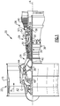
- FIG. 1 schematically illustrates a gas turbine engine 20.
- the gas turbine engine 20 is disclosed herein as a two-spool turbofan that generally incorporates a fan section 22, a compressor section 24, a combustor section 26 and a turbine section 28.
- the fan section 22 drives air along a bypass flow path B in a bypass duct defined within a nacelle 15, and also drives air along a core flow path C for compression and communication into the combustor section 26 then expansion through the turbine section 28.
- FIG. 1 schematic
- the exemplary engine 20 generally includes a low speed spool 30 and a high speed spool 32 mounted for rotation about an engine central longitudinal axis A relative to an engine static structure 36 via several bearing systems 38. It should be understood that various bearing systems 38 at various locations may alternatively or additionally be provided, and the location of bearing systems 38 may be varied as appropriate to the application.
- the low speed spool 30 generally includes an inner shaft 40 that interconnects, a first (or low) pressure compressor 44 and a first (or low) pressure turbine 46.
- the inner shaft 40 is connected to the fan 42 through a speed change mechanism, which in exemplary gas turbine engine 20 is illustrated as a geared architecture 48 to drive a fan 42 at a lower speed than the low speed spool 30.
- the high speed spool 32 includes an outer shaft 50 that interconnects a second (or high) pressure compressor 52 and a second (or high) pressure turbine 54.
- a combustor 56 is arranged in exemplary gas turbine 20 between the high pressure compressor 52 and the high pressure turbine 54.
- a mid-turbine frame 57 of the engine static structure 36 may be arranged generally between the high pressure turbine 54 and the low pressure turbine 46.
- the mid-turbine frame 57 further supports bearing systems 38 in the turbine section 28.
- the inner shaft 40 and the outer shaft 50 are concentric and rotate via bearing systems 38 about the engine central longitudinal axis A which is colline
- the core airflow is compressed by the low pressure compressor 44 then the high pressure compressor 52, mixed and burned with fuel in the combustor 56, then expanded over the high pressure turbine 54 and low pressure turbine 46.
- the mid-turbine frame 57 includes airfoils 59 which are in the core airflow path C.
- the turbines 46, 54 rotationally drive the respective low speed spool 30 and high speed spool 32 in response to the expansion.
- gear system 48 may be located aft of the low pressure compressor, or aft of the combustor section 26 or even aft of turbine section 28, and fan 42 may be positioned forward or aft of the location of gear system 48.
- the engine 20 in one example is a high-bypass geared aircraft engine.
- the engine 20 bypass ratio is greater than about six (6), with an example embodiment being greater than about ten (10)
- the geared architecture 48 is an epicyclic gear train, such as a planetary gear system or other gear system, with a gear reduction ratio of greater than about 2.3
- the low pressure turbine 46 has a pressure ratio that is greater than about five.
- the engine 20 bypass ratio is greater than about ten (10:1)
- the fan diameter is significantly larger than that of the low pressure compressor 44
- the low pressure turbine 46 has a pressure ratio that is greater than about five 5:1.
- Low pressure turbine 46 pressure ratio is pressure measured prior to inlet of low pressure turbine 46 as related to the pressure at the outlet of the low pressure turbine 46 prior to an exhaust nozzle.
- the geared architecture 48 may be an epicycle gear train, such as a planetary gear system or other gear system, with a gear reduction ratio of greater than about 2.3:1 and less than about 5:1. It should be understood, however, that the above parameters are only exemplary of one embodiment of a geared architecture engine and that the present invention is applicable to other gas turbine engines including direct drive turbofans.
- the fan section 22 of the engine 20 is designed for a particular flight condition -- typically cruise at about 0.8 Mach and about 35,000 feet (10,668 meters).
- the flight condition of 0.8 Mach and 35,000 ft (10,668 meters), with the engine at its best fuel consumption - also known as "bucket cruise Thrust Specific Fuel Consumption ('TSFC')" - is the industry standard parameter of lbm of fuel being burned divided by lbf of thrust the engine produces at that minimum point.
- "Low fan pressure ratio” is the pressure ratio across the fan blade alone, without a Fan Exit Guide Vane (“FEGV”) system.
- the low fan pressure ratio as disclosed herein according to one non-limiting embodiment is less than about 1.45.
- Low corrected fan tip speed is the actual fan tip speed in ft/sec divided by an industry standard temperature correction of [(Tram °R) / (518.7 °R)] 0.5 .
- the "Low corrected fan tip speed” as disclosed herein according to one non-limiting embodiment is less than about 1150 ft / second (350.5 meters/second).
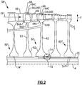
- Figure 2 illustrates a rotor assembly 60 for a section 58 of a gas turbine engine, such as the compressor section 24 of Figure 1 .
- a gas turbine engine such as the compressor section 24 of Figure 1 .
- the disclosure primarily refers to the compressor section 24, other portions of the engine 20 may benefit from the teachings herein, such as the fan and turbine sections 22, 28, towershafts and auxiliary systems. Other systems may also benefit from the teachings herein, including marine and ground based systems.
- the section 58 includes a plurality of rotors 62 each including a disk or hub 63 that carries one or more rotatable blades or airfoils 64.
- the airfoils 64 are rotatable about the engine axis A in a gas path GP, such as core flow path C.
- Each airfoil 64 includes a platform 64A and an airfoil section 64B extending in a spanwise or radial direction R from the platform 64A to a tip 64C.
- a root section 64D of each airfoil 64 extends outwardly from, and is mounted to, a respective hub 63. In some examples, the root section 64D is received in a slot defined by the hub 63.
- the rotor 62 is a blisk or integrated bladed rotor (IBR) in which the airfoils 64 are integrally formed with the hub 63.
- the IBR is a compressor rotor, such as a high pressure compressor rotor of the high pressure compressor 52 or a low pressure compressor rotor of the low pressure compressor 44.
- Various techniques can be utilized to form the IBR, such as casting, additive manufacturing, machining from a solid work piece, or welding individual airfoils 64 to the hub 63.
- One or more rows of vanes 66 are positioned along the engine axis A and adjacent to the airfoils 64 to direct flow in the gas path GP.
- the vanes 66 can be mechanically attached to the engine static structure 38.
- An array of seals 68 are distributed about each row of airfoils 64 to bound the gas path GP.
- One or more of the rotors 62 is mechanically attached or otherwise fixedly secured to an elongated, rotatable shaft 70.
- the shaft 70 is rotatable about the engine axis A.
- the shaft 70 interconnects a turbine and a compressor, such as one of the shafts 40, 50 of Figure 1 .
- the rotor assembly 60 includes at least one annular seal 74.
- the seal 74 can be located at one or more of the stages of the section 58, such as an intermediate stage as illustrated by seal 74, and/or a forwardmost or aftmost stage indicated by seals 74', 74" of rotor assemblies 60', 60" (seals shown in dashed lines).
- Each rotor assembly 60 can have a single seal as illustrated by seals 74, 74' or can have multiple seals as illustrated by seals 74" of rotor assembly 60".
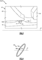
- Figure 3 illustrates an enhanced view of a portion 72 of the rotor assembly 60.
- the annular seal 74 is carried by the shaft 70 for establishing a sealing relationship between the hub 63 of the rotor 62 and the shaft 70 to block or reduce communication of flow between adjacent cavities defined by the rotor 62 and shaft 70.
- a cross section of the shaft 70 can have a circular or otherwise generally elliptical geometry.
- the seal 74 can be a piston ring having a hoop-shaped geometry, as illustrated in Figure 4 .
- the seal 74 is a split ring including a main body 74A extending between first and second ends 74B, 74C. The first end 74B engages with the second end 74C at an interface.
- the main body 74A is continuous to form a full hoop.
- the seal 74 is dimensioned to extend about a circumference of the shaft 70.
- An outer diameter portion 70A of the shaft 70 defines an annular groove 76 that is dimensioned to receive at least a portion of the seal 74.
- the seal 74 is seated in the groove 76 to establish a sealing relationship with an inner diameter portion 63A of the hub 63.
- the seal 74 can be exposed to relatively high temperatures due to proximity to the gas path GP and other portions of the engine 20.
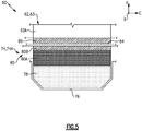
- the seal 74 is a multi-layer seal including a substrate 78 and a coating 80 including a plurality of layers.
- the coating 80 includes at least a first layer 80A and a second layer 80B. At least the substrate 78 is seated in the groove 76, and the coating 80 is situated between the substrate 78 and the hub 63.
- the second layer 80B can define an external surface of the seal 74.
- the inner diameter portion 63A of the hub 63 defines a counter face or seal land.
- the second layer 80B abuts against the inner diameter portion 63A of the hub 63 or is otherwise in close proximity to the seal land to establish a sealing relationship with the hub 63 along an interface 84.
- the first layer 80A can be disposed directly on the substrate 78.
- the second layer 80B can be disposed directly on the first layer 80A.
- one or more layers of material are formed between the substrate 78 and first layer 80A and/or between the first and second layers 80A, 80B.
- the hub 63 includes a third layer 86 deposited on surfaces of the inner diameter portion 63A along the interface 84 to establish the seal land. In other examples, the third layer 86 is omitted.
- the substrate 78 can be made of a first material, the first layer 80A can be made of a second material, and the second layer 80B can be made of a third material.
- the first, second and/or third materials can differ in composition and/or construction.
- the substrate 78 and the rotor 62 can comprise a high temperature metal or metal alloy, such as a nickel alloy.
- Example nickel alloys include nickel chromium alloy sold under the tradename INCONEL® alloy 718 (IN718) and Direct Age Processed Alloy 718 (DA718).
- the substrate 78 is made of IN718 and at least the inner diameter portion 63A of the hub 63 is made of DA718.
- the first layer 80A may be a relatively soft metal or metal alloy coating comprising copper or a copper alloy including aluminum or nickel, for example.
- the first layer 80A is a nickel-based or molybdenum-based metal or metal alloy.
- the second layer 80B can be a low friction coating comprising a solid lubricant, with the second layer 80B having a lesser hardness than the first layer 80A.
- the first layer 80A has a hardness of about 100-300 diamond pyramid hardness (DPH)
- the second layer 80B has a hardness of about 1 gigapascals (GPa) or less measured by means of nanoindentation.
- the solid lubricant can reduce a coefficient of friction (COF) between the seal 74 and the rotor 62 along the interface 84, with the second layer 80B having a relatively lower COF than the first layer 80A of the coating 80.
- COF coefficient of friction
- Example solid lubricants include molybdenum disulfide (MoS2), boron nitride, and tungsten disulfide.
- the solid lubricant can include silicate as a binder.
- Other example solid lubricants can include carbon-based and graphite-based materials.
- the solid lubricant is compounded with another material to form a self-lubricating composite such as a MoS2-ceramic composite.
- Other example solid lubricants include tungsten disulphide (WS 2 ).
- the first layer 80A of the coating 80 is a layer of copper alloy disposed on the substrate 78
- the second layer 80B is a solid lubricant comprising molybdenum disulfide (MoS2) that is deposited as a film on the first layer 80A.
- MoS2 molybdenum disulfide
- a hardness of the copper-based coating can be relatively lower than other materials to reduce wear of the counter face and the solid lubricant that may otherwise occur due to the interface.
- the first layer 80A has a composition, by weight percent, of about 60% to about 95% copper. In some examples, the first layer 80A has a composition, by weight percent, of about 85% to about 95% copper, and aluminum. In other examples, the first layer 80A has a composition, by weight percent, of about 60% to about 65% copper, and nickel. In example, the first layer 80A has a composition of copper including any of the weight percentages disclosed herein, and the balance is aluminum or nickel. For the purposes of this disclosure, the term "about” means ⁇ 3% of the disclosed weight percent value unless otherwise stated.
- the third layer 86 can be a solid lubricant made of any of the materials disclosed herein.
- the third layer 86 comprises molybdenum disulfide (MoS2).
- MoS2 molybdenum disulfide
- the seal 74 may move relative to the hub 63 along the interface 84 in axial, radial and/or circumferential directions X, R, C.
- the axial direction X can be coincidental or parallel to the engine axis A. Sliding or movement of the seal 74 along the interface 84 in the axial and/or circumferential directions X, C may occur due to relatively high vibratory energy in the system.
- the solid lubricant can reduce the COF and frictional heating along the interface 84, which can reduce galling and other wear along the adjacent surfaces and can increase durability of the seal 74 and the rotor 62. Reduced wear can reduce overhaul costs that may otherwise be associated with replacement or refurbishment of the seal 74 and/or rotor 62.
- Figures 6A and 6B illustrate example plots of COF versus cycles of rotor assemblies.
- the x-axis corresponds to the number of cycles of movement of the respective seal relative to the interface.
- the y-axis corresponds to the average COF. Values along the y-axis correspond to movement of the seal in a first direction.
- Figure 6A illustrates curve 88 corresponding to average COF values for a seal having a copper-based coating free of a solid lubricant.
- Figure 6B illustrates curve 90 corresponding to average COF values for the seal 74 having a copper-based coating and a MoS2-based solid lubricant.
- the copper-based coating including a solid lubricant can reduce the average COF as compared to coatings free of a solid lubricant.
- the seal 74 has an average COF of less than 0.2, whereas the average COF of curve 88 is greater than 0.2 and approach 0.5 for a comparable number of cycles.
- the combination of materials of the substrate 78, layers 80A, 80B of coating 80 and/or hub 63 can reduce wear adjacent the first and second ends 74B, 74C of the seal 74 and adjacent portions of the hub 63.
- Figure 7 illustrates a process for forming a rotor assembly, including any of the seals and rotor assemblies disclosed herein. Reference is made to the seal 74 and rotor assembly 60 of Figures 3-5 for illustrative purposes.
- a coating including one or more layers of material is removed from surfaces of substrate 78 at step 94, including at least a previously applied second layer 80B comprised of a solid lubricant.
- the first layer 80A is deposited or otherwise formed on the substrate 78 at step 96.
- the first layer 80A can be formed on the substrate 78 utilizing various techniques, such as by plasma spray deposition or another thermal spraying technique.
- Other example techniques for forming the first layer 80A can include physical vapor deposition (PVD) and chemical vapor deposition (CVD).
- step 94 includes removing a previously applied first layer 80A such as a layer of copper alloy from the substrate 78 prior to step 96.
- the previously applied first layer 80A may be removed after about 10,000-12,000 operating cycles of the engine, whereas a previously applied second layer 80B may be removed after a lesser number of operating cycles, such as approximately 1000 operating cycles, for example.
- the second layer 80B comprising a solid lubricant is deposited or otherwise formed on the first layer 80A.
- the third layer 86 comprising a solid lubricant is deposited or otherwise formed on the hub 63.
- a previously applied third layer 86 can be removed prior to step 96.
- the second and third layers 80B, 86 can be applied utilizing various techniques, such as brushing, swabbing, or spraying including any of the spraying techniques disclosed herein.
- the second and/or third layers 80B, 86 are applied by physical vapor deposition (PVD) or chemical vapor deposition (CVD).
- the first, second and/or third layers 80A, 80B, 86 may include one or more sublayers.
- One or more layers of material may be formed on and/or between the layers 80A, 80B, 86.
- Various finishing operations can be applied once the respective layers 80A, 80B, 86 are formed.
Applications Claiming Priority (1)
| Application Number | Priority Date | Filing Date | Title |
|---|---|---|---|
| US16/104,153 US10920617B2 (en) | 2018-08-17 | 2018-08-17 | Gas turbine engine seal ring assembly |
Publications (2)
| Publication Number | Publication Date |
|---|---|
| EP3611348A1 true EP3611348A1 (de) | 2020-02-19 |
| EP3611348B1 EP3611348B1 (de) | 2024-04-24 |
Family
ID=67587682
Family Applications (1)
| Application Number | Title | Priority Date | Filing Date |
|---|---|---|---|
| EP19191120.5A Active EP3611348B1 (de) | 2018-08-17 | 2019-08-09 | Dichtungsringanordnung für gasturbinentriebwerk |
Country Status (2)
| Country | Link |
|---|---|
| US (1) | US10920617B2 (de) |
| EP (1) | EP3611348B1 (de) |
Cited By (2)
| Publication number | Priority date | Publication date | Assignee | Title |
|---|---|---|---|---|
| EP3719265A1 (de) * | 2019-04-03 | 2020-10-07 | Raytheon Technologies Corporation | Rotierende kohlenstoffkolbenringdichtung |
| EP3783201A1 (de) * | 2019-08-07 | 2021-02-24 | Raytheon Technologies Corporation | Dichtungsanordnung für ein gasturbinentriebwerk |
Families Citing this family (4)
| Publication number | Priority date | Publication date | Assignee | Title |
|---|---|---|---|---|
| US11448082B2 (en) | 2020-07-01 | 2022-09-20 | Raytheon Technologies Corporation | Wear resistant, self-lubricating static seal |
| US11952916B2 (en) | 2020-08-14 | 2024-04-09 | Rtx Corporation | Self-lubricating blade root/disk interface |
| US11542819B2 (en) * | 2021-02-17 | 2023-01-03 | Pratt & Whitney Canada Corp. | Split ring seal for gas turbine engine rotor |
| US11506071B2 (en) * | 2021-03-02 | 2022-11-22 | Raytheon Technologies Corporation | Piston ring shuttle carrier |
Citations (5)
| Publication number | Priority date | Publication date | Assignee | Title |
|---|---|---|---|---|
| US5537814A (en) * | 1994-09-28 | 1996-07-23 | General Electric Company | High pressure gas generator rotor tie rod system for gas turbine engine |
| JPH10183327A (ja) * | 1996-10-28 | 1998-07-14 | Nippon Piston Ring Co Ltd | 摺動部材のなじみ性溶射被膜層 |
| JP2007023352A (ja) * | 2005-07-19 | 2007-02-01 | Ishikawajima Harima Heavy Ind Co Ltd | 皮膜形成方法 |
| EP2453150A1 (de) * | 2010-11-10 | 2012-05-16 | United Technologies Corporation | Dichtungsanordnung |
| EP2562364A1 (de) * | 2011-08-24 | 2013-02-27 | United Technologies Corporation | Drehende Turbomaschinendichtung |
Family Cites Families (35)
| Publication number | Priority date | Publication date | Assignee | Title |
|---|---|---|---|---|
| US3497272A (en) * | 1966-06-20 | 1970-02-24 | Berliet Automobiles | Friction elements for machines subjected to high loads |
| IT1025260B (it) * | 1973-11-16 | 1978-08-10 | Mtu Muenchen Gmbh | Turbina a raffreddamento interno della corona e con posizioni prescritte di rottura |
| US3847506A (en) * | 1973-11-29 | 1974-11-12 | Avco Corp | Turbomachine rotor |
| US3914178A (en) * | 1974-01-23 | 1975-10-21 | Amerace Corp | Wear reducing coating |
| US4536932A (en) | 1982-11-22 | 1985-08-27 | United Technologies Corporation | Method for eliminating low cycle fatigue cracking in integrally bladed disks |
| US4875830A (en) | 1985-07-18 | 1989-10-24 | United Technologies Corporation | Flanged ladder seal |
| US4950503A (en) * | 1989-01-23 | 1990-08-21 | Olin Corporation | Process for the coating of a molybdenum base |
| US5292138A (en) * | 1992-09-21 | 1994-03-08 | General Elecric Company | Rotor to rotor split ring seal |
| DE59506236D1 (de) * | 1995-02-02 | 1999-07-22 | Sulzer Innotec Ag | Gleitverschleissfeste Verbundbeschichtung |
| US5632600A (en) | 1995-12-22 | 1997-05-27 | General Electric Company | Reinforced rotor disk assembly |
| JP4023872B2 (ja) * | 1997-06-26 | 2007-12-19 | 大豊工業株式会社 | 斜板式コンプレッサー用斜板 |
| US5988980A (en) | 1997-09-08 | 1999-11-23 | General Electric Company | Blade assembly with splitter shroud |
| US6422818B2 (en) | 1998-08-07 | 2002-07-23 | General Electric Company | Lubricating system for thermal medium delivery parts in a gas turbine |
| US7021042B2 (en) | 2002-12-13 | 2006-04-04 | United Technologies Corporation | Geartrain coupling for a turbofan engine |
| AT503986B1 (de) * | 2006-08-02 | 2008-05-15 | Miba Gleitlager Gmbh | Laufschicht für ein lagerelement |
| US7887299B2 (en) | 2007-06-07 | 2011-02-15 | Honeywell International Inc. | Rotary body for turbo machinery with mistuned blades |
| US9133720B2 (en) | 2007-12-28 | 2015-09-15 | United Technologies Corporation | Integrally bladed rotor with slotted outer rim |
| US9273563B2 (en) | 2007-12-28 | 2016-03-01 | United Technologies Corporation | Integrally bladed rotor with slotted outer rim |
| DE102009007468A1 (de) | 2009-02-04 | 2010-08-19 | Mtu Aero Engines Gmbh | Integral beschaufelte Rotorscheibe für eine Turbine |
| US8157514B2 (en) | 2009-03-19 | 2012-04-17 | Honeywell International Inc. | Components for gas turbine engines |
| EP2520768A1 (de) * | 2011-05-02 | 2012-11-07 | MTU Aero Engines AG | Dichteinrichtung für einen integral beschaufelten Rotorgrundkörper einer Strömungsmaschine |
| EP2520764A1 (de) | 2011-05-02 | 2012-11-07 | MTU Aero Engines GmbH | Schaufel mit gekühltem Schaufelfuss |
| CN202790112U (zh) * | 2012-03-16 | 2013-03-13 | 刘利利 | 一种双金属轴承 |
| US10077807B2 (en) * | 2012-03-27 | 2018-09-18 | Ntn Corporation | Composite plain bearing, cradle guide, and sliding nut |
| CA2910458A1 (en) * | 2013-04-29 | 2014-11-06 | Xeicle Limited | A thermodynamic machine |
| US9051987B2 (en) * | 2013-08-14 | 2015-06-09 | Caterpillar Inc. | Strut wear bands |
| EP3215290B1 (de) * | 2014-11-04 | 2021-11-24 | Dresser-Rand Company | System und verfahren zur generativen fertigung von turbomaschinenbauteilen |
| GB201506197D0 (en) | 2015-04-13 | 2015-05-27 | Rolls Royce Plc | Rotor damper |
| CN205330928U (zh) * | 2016-01-29 | 2016-06-22 | 江苏盈科汽车空调有限公司 | 一种耐磨空调压缩机缸体 |
| CN205330927U (zh) * | 2016-01-29 | 2016-06-22 | 江苏盈科汽车空调有限公司 | 一种使用寿命长的空调压缩机缸体 |
| CN205533082U (zh) * | 2016-01-29 | 2016-08-31 | 江苏盈科汽车空调有限公司 | 一种使用寿命长的汽车压缩机斜盘组件 |
| CN106048400B (zh) * | 2016-02-23 | 2018-02-16 | 江苏盈科汽车空调有限公司 | 一种用于空调压缩机缸体的球墨铸铁及其制备方法 |
| CN105861886B (zh) * | 2016-02-23 | 2018-11-13 | 江苏盈科汽车空调有限公司 | 一种用于空调压缩机缸体的铝硅合金及其制备方法 |
| PL3633253T3 (pl) * | 2017-05-22 | 2023-12-11 | Nippon Steel Corporation | Połączenie gwintowe dla rur lub przewodów rurowych oraz sposób wykonywania połączenia gwintowego dla rur lub przewodów rurowych |
| CN108547874A (zh) * | 2018-07-11 | 2018-09-18 | 如皋市福锴金属制品有限公司 | 一种双金属轴承 |
-
2018
- 2018-08-17 US US16/104,153 patent/US10920617B2/en active Active
-
2019
- 2019-08-09 EP EP19191120.5A patent/EP3611348B1/de active Active
Patent Citations (5)
| Publication number | Priority date | Publication date | Assignee | Title |
|---|---|---|---|---|
| US5537814A (en) * | 1994-09-28 | 1996-07-23 | General Electric Company | High pressure gas generator rotor tie rod system for gas turbine engine |
| JPH10183327A (ja) * | 1996-10-28 | 1998-07-14 | Nippon Piston Ring Co Ltd | 摺動部材のなじみ性溶射被膜層 |
| JP2007023352A (ja) * | 2005-07-19 | 2007-02-01 | Ishikawajima Harima Heavy Ind Co Ltd | 皮膜形成方法 |
| EP2453150A1 (de) * | 2010-11-10 | 2012-05-16 | United Technologies Corporation | Dichtungsanordnung |
| EP2562364A1 (de) * | 2011-08-24 | 2013-02-27 | United Technologies Corporation | Drehende Turbomaschinendichtung |
Cited By (4)
| Publication number | Priority date | Publication date | Assignee | Title |
|---|---|---|---|---|
| EP3719265A1 (de) * | 2019-04-03 | 2020-10-07 | Raytheon Technologies Corporation | Rotierende kohlenstoffkolbenringdichtung |
| US11028713B2 (en) | 2019-04-03 | 2021-06-08 | Raytheon Technologies Corporation | Rotating carbon piston ring seal |
| EP3783201A1 (de) * | 2019-08-07 | 2021-02-24 | Raytheon Technologies Corporation | Dichtungsanordnung für ein gasturbinentriebwerk |
| US11149651B2 (en) | 2019-08-07 | 2021-10-19 | Raytheon Technologies Corporation | Seal ring assembly for a gas turbine engine |
Also Published As
| Publication number | Publication date |
|---|---|
| US20200056506A1 (en) | 2020-02-20 |
| US10920617B2 (en) | 2021-02-16 |
| EP3611348B1 (de) | 2024-04-24 |
Similar Documents
| Publication | Publication Date | Title |
|---|---|---|
| EP3611348B1 (de) | Dichtungsringanordnung für gasturbinentriebwerk | |
| EP3109514B1 (de) | Wälzkörperkäfig für getriebeturbolüfter | |
| US9169739B2 (en) | Hybrid blade outer air seal for gas turbine engine | |
| EP3613950B1 (de) | Aus laminat geformte schaufelaussenluftdichtung mit radialen stützhaken | |
| EP3587740B1 (de) | Dichtungsanordnung für ein gasturbinentriebwerk und montageverfahren | |
| US10385719B2 (en) | Variable vane bushing | |
| EP2820297B1 (de) | Leichtgewichtige bläserantriebsturbine | |
| EP3078807B2 (de) | Kühlkanäle für eine gasturbinenmotorkomponente | |
| EP3323999B1 (de) | Endwandbogensegmente mit abdeckung über verbindungsstelle | |
| EP2987960B1 (de) | Keramikbeschichtungssystem und -verfahren | |
| EP3323986B1 (de) | Schaufel mit geometrisch segmentiertem beschichtungsabschnitt | |
| EP3739168A1 (de) | Cmc-boas-anordnung | |
| EP4063619A1 (de) | Aussendeckband für einen gas turbinenmotor | |
| EP3783201A1 (de) | Dichtungsanordnung für ein gasturbinentriebwerk | |
| EP2971689B1 (de) | Mehrfachbeschichtungskonfiguration | |
| EP4006310A1 (de) | Gleitringdichtungsanordnung mit reduziertem gleichgewichtsverhältnis | |
| EP3196419A1 (de) | Äussere laufschaufelluftdichtung mit einer oberflächenschicht mit taschen | |
| EP3056742A1 (de) | Verdichterschaufel | |
| EP3608512B1 (de) | Gasturbinentriebwerk mit dichtfläche für schaufelaussendichtung | |
| EP4080018B1 (de) | Schaufelbogensegment mit flansch mit stufe und verfahren zur herstellung eines schaufelbogensegments | |
| EP3470627B1 (de) | Gasturbinenmotorschaufel | |
| EP3660275B1 (de) | Abreibbare beschichtung für gerillte boas dichtung | |
| EP4086435A1 (de) | Maschinell bearbeitbare beschichtung mit variabler dicke für plattformdichtungen | |
| EP3808940A1 (de) | Cmc-schaufel mit kühllöchern |
Legal Events
| Date | Code | Title | Description |
|---|---|---|---|
| PUAI | Public reference made under article 153(3) epc to a published international application that has entered the european phase |
Free format text: ORIGINAL CODE: 0009012 |
|
| STAA | Information on the status of an ep patent application or granted ep patent |
Free format text: STATUS: THE APPLICATION HAS BEEN PUBLISHED |
|
| AK | Designated contracting states |
Kind code of ref document: A1 Designated state(s): AL AT BE BG CH CY CZ DE DK EE ES FI FR GB GR HR HU IE IS IT LI LT LU LV MC MK MT NL NO PL PT RO RS SE SI SK SM TR |
|
| AX | Request for extension of the european patent |
Extension state: BA ME |
|
| STAA | Information on the status of an ep patent application or granted ep patent |
Free format text: STATUS: REQUEST FOR EXAMINATION WAS MADE |
|
| 17P | Request for examination filed |
Effective date: 20200818 |
|
| RBV | Designated contracting states (corrected) |
Designated state(s): AL AT BE BG CH CY CZ DE DK EE ES FI FR GB GR HR HU IE IS IT LI LT LU LV MC MK MT NL NO PL PT RO RS SE SI SK SM TR |
|
| STAA | Information on the status of an ep patent application or granted ep patent |
Free format text: STATUS: EXAMINATION IS IN PROGRESS |
|
| STAA | Information on the status of an ep patent application or granted ep patent |
Free format text: STATUS: EXAMINATION IS IN PROGRESS |
|
| 17Q | First examination report despatched |
Effective date: 20201103 |
|
| RAP1 | Party data changed (applicant data changed or rights of an application transferred) |
Owner name: RAYTHEON TECHNOLOGIES CORPORATION |
|
| RAP3 | Party data changed (applicant data changed or rights of an application transferred) |
Owner name: RTX CORPORATION |
|
| GRAP | Despatch of communication of intention to grant a patent |
Free format text: ORIGINAL CODE: EPIDOSNIGR1 |
|
| STAA | Information on the status of an ep patent application or granted ep patent |
Free format text: STATUS: GRANT OF PATENT IS INTENDED |
|
| INTG | Intention to grant announced |
Effective date: 20231127 |
|
| GRAS | Grant fee paid |
Free format text: ORIGINAL CODE: EPIDOSNIGR3 |
|
| GRAA | (expected) grant |
Free format text: ORIGINAL CODE: 0009210 |
|
| STAA | Information on the status of an ep patent application or granted ep patent |
Free format text: STATUS: THE PATENT HAS BEEN GRANTED |
|
| AK | Designated contracting states |
Kind code of ref document: B1 Designated state(s): AL AT BE BG CH CY CZ DE DK EE ES FI FR GB GR HR HU IE IS IT LI LT LU LV MC MK MT NL NO PL PT RO RS SE SI SK SM TR |
|
| REG | Reference to a national code |
Ref country code: GB Ref legal event code: FG4D |
|
| REG | Reference to a national code |
Ref country code: CH Ref legal event code: EP |