EP3611071B1 - Energieabsorbierender aufkletterschutz und zugfahrzeug mit energieabsorbierendem aufkletterschutz - Google Patents
Energieabsorbierender aufkletterschutz und zugfahrzeug mit energieabsorbierendem aufkletterschutz Download PDFInfo
- Publication number
- EP3611071B1 EP3611071B1 EP18832693.8A EP18832693A EP3611071B1 EP 3611071 B1 EP3611071 B1 EP 3611071B1 EP 18832693 A EP18832693 A EP 18832693A EP 3611071 B1 EP3611071 B1 EP 3611071B1
- Authority
- EP
- European Patent Office
- Prior art keywords
- energy
- guiding
- guiding cylinder
- collision
- creeper
- Prior art date
- Legal status (The legal status is an assumption and is not a legal conclusion. Google has not performed a legal analysis and makes no representation as to the accuracy of the status listed.)
- Active
Links
Images


Classifications
-
- B—PERFORMING OPERATIONS; TRANSPORTING
- B61—RAILWAYS
- B61F—RAIL VEHICLE SUSPENSIONS, e.g. UNDERFRAMES, BOGIES OR ARRANGEMENTS OF WHEEL AXLES; RAIL VEHICLES FOR USE ON TRACKS OF DIFFERENT WIDTH; PREVENTING DERAILING OF RAIL VEHICLES; WHEEL GUARDS, OBSTRUCTION REMOVERS OR THE LIKE FOR RAIL VEHICLES
- B61F19/00—Wheel guards; Bumpers; Obstruction removers or the like
- B61F19/04—Bumpers or like collision guards
-
- B—PERFORMING OPERATIONS; TRANSPORTING
- B61—RAILWAYS
- B61D—BODY DETAILS OR KINDS OF RAILWAY VEHICLES
- B61D15/00—Other railway vehicles, e.g. scaffold cars; Adaptations of vehicles for use on railways
- B61D15/06—Buffer cars; Arrangements or construction of railway vehicles for protecting them in case of collisions
-
- B—PERFORMING OPERATIONS; TRANSPORTING
- B61—RAILWAYS
- B61G—COUPLINGS; DRAUGHT AND BUFFING APPLIANCES
- B61G11/00—Buffers
- B61G11/16—Buffers absorbing shocks by permanent deformation of buffer element
-
- B—PERFORMING OPERATIONS; TRANSPORTING
- B60—VEHICLES IN GENERAL
- B60R—VEHICLES, VEHICLE FITTINGS, OR VEHICLE PARTS, NOT OTHERWISE PROVIDED FOR
- B60R19/00—Wheel guards; Radiator guards, e.g. grilles; Obstruction removers; Fittings damping bouncing force in collisions
- B60R19/02—Bumpers, i.e. impact receiving or absorbing members for protecting vehicles or fending off blows from other vehicles or objects
- B60R19/24—Arrangements for mounting bumpers on vehicles
- B60R19/26—Arrangements for mounting bumpers on vehicles comprising yieldable mounting means
- B60R19/34—Arrangements for mounting bumpers on vehicles comprising yieldable mounting means destroyed upon impact, e.g. one-shot type
-
- B—PERFORMING OPERATIONS; TRANSPORTING
- B60—VEHICLES IN GENERAL
- B60R—VEHICLES, VEHICLE FITTINGS, OR VEHICLE PARTS, NOT OTHERWISE PROVIDED FOR
- B60R19/00—Wheel guards; Radiator guards, e.g. grilles; Obstruction removers; Fittings damping bouncing force in collisions
- B60R19/02—Bumpers, i.e. impact receiving or absorbing members for protecting vehicles or fending off blows from other vehicles or objects
- B60R2019/026—Buffers, i.e. bumpers of limited extent
-
- B—PERFORMING OPERATIONS; TRANSPORTING
- B60—VEHICLES IN GENERAL
- B60Y—INDEXING SCHEME RELATING TO ASPECTS CROSS-CUTTING VEHICLE TECHNOLOGY
- B60Y2200/00—Type of vehicle
- B60Y2200/30—Railway vehicles
-
- B—PERFORMING OPERATIONS; TRANSPORTING
- B61—RAILWAYS
- B61D—BODY DETAILS OR KINDS OF RAILWAY VEHICLES
- B61D17/00—Construction details of vehicle bodies
- B61D17/04—Construction details of vehicle bodies with bodies of metal; with composite, e.g. metal and wood body structures
- B61D17/06—End walls
-
- F—MECHANICAL ENGINEERING; LIGHTING; HEATING; WEAPONS; BLASTING
- F16—ENGINEERING ELEMENTS AND UNITS; GENERAL MEASURES FOR PRODUCING AND MAINTAINING EFFECTIVE FUNCTIONING OF MACHINES OR INSTALLATIONS; THERMAL INSULATION IN GENERAL
- F16F—SPRINGS; SHOCK-ABSORBERS; MEANS FOR DAMPING VIBRATION
- F16F7/00—Vibration-dampers; Shock-absorbers
- F16F7/12—Vibration-dampers; Shock-absorbers using plastic deformation of members
Definitions
- the present disclosure relates to a field of train protection equipment, and more particularly to an energy-absorbing anti-creeper and a train vehicle with the energy-absorbing anti-creeper.
- the related energy-absorbing anti-creeper only absorbs collision energy by the compression deformation of an energy-absorbing material, and the internal energy-absorbing material cannot be discharged from a closed space, so that the energy-absorbing material cannot be further compressed when being compressed to a certain extent, resulting in lower energy-absorbing efficiency and lower use safety.
- CN102398558A discloses a collision buffering energy absorption device.
- a bottom plate is connected with a guide lug boss, and has a certain distance away from a friction guide plate; an energy absorption pipe with an axial groove is sleeved on the guide lug boss; and a substrate is arranged at the other end of the energy absorption pipe.
- the substrate drives the energy absorption pipe to move towards the bottom plate; in the moving process, partial energy is absorbed through the friction between the energy absorption pipe and the guide lug boss; meanwhile, the sectional area of the guide lug boss is larger when the guide lug boss approaches the bottom plate, the energy absorption pipe is torn in the axial groove at a certain moment, and partial energy is absorbed in the tearing process; the torn part of the energy absorption pipe is bent to enter a space between the friction guide plate and the bottom plate, and partial energy is absorbed through friction in the advancing process; and the buffering energy absorption effect is achieved finally.
- the collision buffering energy absorption device is simple in structure, easy to manufacture, and low in cost, absorbs energy load uniformly, has high capacity and can serve as good passive safety protection equipment.
- WO2009/072843A2 discloses a tube buffer for railway vehicles, installed to the fore of a railway vehicle to absorb impact energy generated in the event of a collision of the railway vehicle.
- the die of the tube buffer expands a tube by impact energy, and simultaneously the blades of the die cut the expanded tube, so that the efficiency of absorbing impact energy is excellent and a small installation space is required.
- a stabilizer provided on the tube buffer absorbs stage conversion impact generated when an impact energy absorbing stage is converted into a subsequent impact energy absorbing stage while the tube buffer absorbs impact energy in several stages, thus allowing the impact energy to be smoothly absorbed, therefore protecting drivers and passengers in case of an accident, and preventing a railway vehicle structure from being broken or damaged.
- an energy-absorbing anti-creeper and a train vehicle with the energy-absorbing anti-creeper is provided, which is intended to solve the problem in the related technology of low energy-absorbing efficiency of an energy-absorbing anti-creeper.
- the present invention provides an energy-absorbing anti-creeper, which includes: a guiding cylinder, a first end of the guiding cylinder being configured to be in assembly connection with a train; an energy-absorbing material, filled in the guiding cylinder; a collision mechanism, arranged at a second end of the guiding cylinder; and a discharging mechanism for discharging the energy-absorbing material being arranged at the first end of the guiding cylinder; wherein the first end of the guiding cylinder and the second end of the guiding cylinder are two opposite ends of the guiding cylinder, and the energy-absorbing material is extruded to deform when a collision occurs between the collision mechanism and a collision object and then is discharged by the discharging mechanism so as to buffer an collision energy of the collision object.
- the discharging mechanism includes: a guiding cone, covering an opening of the first end of the guiding cylinder.
- a gap is provided between the guiding cone and a cylinder edge of the first end of the guiding cylinder, the gap forming a passage for discharging the energy-absorbing material.
- the guiding cylinder is of cylindrical, and an end face of the guiding cone is provided with a flange portion coupled to the guiding cylinder.
- the energy-absorbing anti-creeper includes: a connecting flange, coupled to the guiding cone and disposed on the first end of the guiding cylinder; and a guiding ring, coupled to the connecting flange, wherein the guiding ring extends along a circumferential direction of the guiding cylinder, and a passage for discharging the energy-absorbing material is formed between the guiding ring and an inner wall surface of the guiding cone.
- the guiding ring is of annular
- the discharging mechanism further includes: a plurality of rear cutters, the plurality of rear cutters being spaced apart on the guiding ring along a circumferential direction of the guiding ring.
- An extrusion groove is formed between two adjacent rear cutters in the plurality of rear cutters, and the energy-absorbing material is cut into a plurality of pieces by each of the plurality of rear cutters in a process of being extruded by the collision mechanism and discharged from a gap between the extrusion groove and the inner wall surface of the guiding cone.
- the collision mechanism includes: a pressing plate, arranged inside a cylinder body of the second end of the guiding cylinder and abutted against the energy-absorbing material, the pressing plate is configured to extrude the energy-absorbing material when colliding with the collision object.
- the pressing plate is coupled to an inner wall of the guiding cylinder by a shear pin.
- the energy-absorbing anti-creeper includes an annular flange abutting against the inner wall of the guiding cylinder, wherein the annular flange is arranged along a circumferential direction of the pressing plate, and the annular flange extends along an axial direction of the guiding cylinder.
- the collision mechanism further includes: a collision plate, arranged at the second end of the guiding cylinder. An end face, facing the guiding cylinder, of the collision plate, is coupled to the pressing plate, and an end face, facing away from the guiding cylinder, of the collision plate is provided with anti-creeping teeth for contacting the collision object.
- the collision mechanism further includes: a plurality of front cutters, arranged on the end face of the collision plate facing the guiding cylinder.
- the plurality of front cutters are spaced apart along a circumferential direction of an inner wall of the guiding cylinder to cut the guiding cylinder along a movement direction of the collision plate when the collision mechanism is collided by the collision object.
- the collision mechanism further includes: a guiding groove, provided on the end face of the collision plate facing the guiding cylinder.
- the guiding groove surrounds a circumferential direction of the guiding cylinder such that an end wall of the guiding cylinder is curled along the guiding groove when being cut and extruded.
- a position of the guiding cylinder corresponding to each of the plurality of front cutters is provided with a preset defect groove, the preset defect groove extending along the axial direction of the guiding cylinder.
- Some embodiments of the present disclosure provide a train vehicle, which includes an energy-absorbing anti-creeper.
- the energy-absorbing anti-creeper is the energy-absorbing anti-creeper as mentioned above.
- the plurality of energy-absorbing anti-creepers are arranged at front and rear ends of the train vehicle respectively.
- the energy-absorbing anti-creeper applying the technical solution of the present disclosure includes: a guiding cylinder, an energy-absorbing material and a collision mechanism.
- a first end of the guiding cylinder is configured to be in assembly connection with a train.
- the energy-absorbing material is filled in the guiding cylinder.
- the collision mechanism is arranged at a second end of the guiding cylinder.
- the first end of the guiding cylinder and the second end of the guiding cylinder are two opposite ends of the guiding cylinder.
- a discharging mechanism for discharging the energy-absorbing material is arranged at the first end of the guiding cylinder.
- the energy-absorbing material is extruded to deform when a collision occurs between the collision mechanism and a collision object and is discharged by the discharging mechanism so as to buffer the collision energy of the collision object.
- the energy-absorbing material in the energy-absorbing anti-creeper can be discharged from the discharging mechanism in a process of being extruded when a train is collided, thereby effectively increasing energy-absorbing efficiency, and solving the problem in the related technology of low energy-absorbing efficiency of an energy-absorbing anti-creeper.
- the drawings include the following reference signs: 10, guiding cylinder; 20, energy-absorbing material; 30, collision mechanism; 31, pressing plate; 32, shear pin; 33, annular flange; 34, collision plate; 35, front cutter; 36, guiding groove; 37, preset defect groove; 38, anti-creeping tooth; 40, discharging mechanism; 41, guiding cone; 42, guiding ring; 43, rear cutter; and 44, extrusion groove.
- an energy-absorbing anti-creeper includes: a guiding cylinder 10, an energy-absorbing material 20; a collision mechanism 30; and a discharging mechanism 40 for discharging the energy-absorbing material 20 being arranged at the first end of the guiding cylinder 10.
- a first end of the guiding cylinder 10 is configured to be in assembly connection with a train.
- the energy-absorbing material 20 is filled in the guiding cylinder 10.
- the collision mechanism 30 is arranged at a second end of the guiding cylinder 10.
- the first end of the guiding cylinder 10 and the second end of the guiding cylinder 10 are two opposite ends of the guiding cylinder 10.
- the energy-absorbing material 20 is extruded to deform when a collision occurs between the collision mechanism 30 and a collision object and then is discharged by the discharging mechanism 40 so as to buffer an collision energy of the collision object.
- An energy-absorbing anti-creeper applying the technical solution of the present disclosure includes a guiding cylinder 10, an energy-absorbing material 20 and a collision mechanism 30.
- a first end of the guiding cylinder 10 is configured to be in assembly connection with a train.
- the energy-absorbing material 20 is filled in the guiding cylinder 10.
- the collision mechanism 30 is arranged at a second end of the guiding cylinder 10.
- the first end of the guiding cylinder 10 and the second end of the guiding cylinder 10 are two opposite ends of the guiding cylinder 10.
- a discharging mechanism 40 for discharging the energy-absorbing material 20 is arranged at the first end of the guiding cylinder 10.
- the energy-absorbing material 20 is extruded to deform when a collision occurs between the collision mechanism 30 and a collision object and then is discharged by the discharging mechanism 40 so as to buffer the collision energy of the collision object.
- the energy-absorbing material 20 in the energy-absorbing anti-creeper can be discharged from the discharging mechanism 40 in the process of being extruded when a train is collided, thereby effectively increasing energy-absorbing efficiency, and solving the problem in the related technology of low energy-absorbing efficiency of an energy-absorbing anti-creeper.
- the first end of the guiding cylinder 10 is provided with a mounting seat connected to the train, and the energy-absorbing anti-creeper is in assembly connection with the train by the mounting seat.
- the energy-absorbing material 20 is a material such as honeycomb aluminum, foamed aluminum, or glass fiber reinforced plastic.
- the guiding cylinder 10 is cylindrical.
- the discharging mechanism 40 includes: a guiding cone 41.
- the guiding cone 41 covers an opening of the first end of the guiding cylinder 10.
- An end face of the guiding cone 41 is provided with a flange portion coupled to the guiding cylinder 10.
- the energy-absorbing anti-creeper includes: a connecting flange, coupled to the guiding cone 41 and disposed on the first end of the guiding cylinder 10; and a guiding ring 42, coupled to the connecting flange.
- the flange portion on the guiding cone 41 is coupled to the connecting flange on the guiding cylinder 10 by a bolt.
- the guiding ring 42 is annular and adapted to a diameter of the guiding cylinder 10.
- the guiding ring 42 extends along a circumferential direction of the guiding cylinder 10. A central portion of an inner end face of the guiding cone 41 convexly extends toward the inside of the guiding cylinder 10.
- the passage for discharging the energy-absorbing material 20 is formed between the guiding ring 42 and an inner wall surface of the guiding cone 41.
- the energy-absorbing material 20 in the guiding cylinder 10 is extruded through the gap between the guiding ring 42 and the inner wall surface of the guiding cone 41 when being extruded to achieve the effect of enhancing the buffer force.
- the discharging mechanism 40 also includes: a plurality of rear cutters 43, the plurality of rear cutters 43 being spaced apart on the guiding ring 42 along a circumferential direction of the guiding ring 42.
- An extrusion groove 44 is formed between two adjacent rear cutters 43 in the plurality of rear cutters 43, and the energy-absorbing material 20 is cut into a plurality of pieces by each of the plurality of rear cutters 43 in a process of being extruded by the collision mechanism 30 and discharged from a gap between the corresponding extrusion groove 44 and the inner wall surface of the guiding cone 41.
- the energy-absorbing material 20 of which the density is rapidly increased after being extruded can be cut into a plurality of small pieces, thereby facilitating the discharge of the energy-absorbing material 20, reducing the range of the energy-absorbing dead zone of the energy-absorbing material 20, and improving the buffer energy-absorbing capacity.
- the collision mechanism 30 includes a pressing plate 31 and a collision plate 34. Both the pressing plate 31 and the collision plate 34 are arranged at the second end of the guiding cylinder 10.
- the pressing plate 31 is arranged inside a cylinder body and abutted against one end of the energy-absorbing material 20 for extruding the energy-absorbing material 20 when colliding with the collision object.
- the pressing plate 31 is coupled to an inner wall of the guiding cylinder 10 by a shear pin 32.
- An end face, facing the guiding cylinder 10, of the collision plate 34 is connected to the pressing plate 31, and an end face, facing away from the guiding cylinder 10, of the collision plate 34, is provided with anti-creeping teeth 38 for contacting the collision object.
- an annular connecting portion is arranged between the collision plate 34 and the pressing plate 31.
- the collision plate 34 is connected to the pressing plate 31 by the annular connection portion and integrated into one body.
- the plurality of anti-creeping teeth 38 are spaced apart on a collision surface of the collision plate 34 along a transverse direction of the collision plate 34.
- the anti-creeping teeth 38 directly collide with the collision object.
- the energy-absorbing material 20 in the inside of the guiding cylinder 10 is extruded by the collision plate 34 and the pressing plate 31.
- the shear pin 32 for connecting the pressing plate 31 is sheared so that the pressing plate 31 applies an impact force to the energy-absorbing material 20.
- the energy-absorbing material 20 near one end of the discharging mechanism 40 is extruded through the gap between the guiding ring 42 and the inner wall surface of the guiding cone 41.
- the guiding cone 41 guides the energy-absorbing material 20 in the process of discharging the energy-absorbing material 20 through the gap between the guiding ring 42 and the inner wall surface of the guiding cone 41.
- the energy-absorbing material is guided to the rear cutters 43 and the extrusion groove 44.
- the energy-absorbing anti-creeper includes an annular flange 33 abutting against the inner wall of the guiding cylinder 10, wherein the annular flange 33 is arranged along a circumferential direction of the pressing plate 31.
- the annular flange 33 extends for a certain length along an axial direction of the guiding cylinder 10.
- the pressing plate 31 has a thickness by providing the annular flange 33 on the pressing plate 31, thereby increasing the contact area of the pressing plate 31 with the inner wall of the guiding cylinder 10 to ensure that the pressing plate 31 can stably extrude the energy-absorbing material 20 under the action of a large impact force.
- a contact portion of the pressing plate 31 and the guiding cylinder 10 is not deformed, and achieves the function of vertical anti-creeping together with the anti-creeping teeth 38.
- the collision mechanism 30 further includes: a plurality of front cutters 35.
- the plurality of front cutters 35 are arranged on the end face of the collision plate 34 facing the guiding cylinder 10.
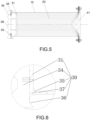
- the plurality of front cutters 35 are spaced apart along a circumferential direction of an inner wall of the guiding cylinder 10. As shown in Fig. 5 , when the collision mechanism 30 is collided by the collision object, the plurality of front cutters 35 cut a part of the inner wall of the guiding cylinder 10 along a movement direction of the collision plate 34.
- a portion of the cut part is curled toward the inside of the guiding cylinder 10, and the remaining portion of the cut part is curled toward the outside of the guiding cylinder 10 under the action of a rear end wall of the collision plate 34, thereby increasing the pushing resistance.
- the effective energy-absorbing stroke of the entire energy-absorbing anti-creeper is increased, thereby improving the buffer energy-absorbing effect.
- the collision mechanism 30 further includes a guiding groove 36.
- the guiding groove 36 is provided on the end face of the collision plate 34 facing the guiding cylinder 10.
- the guiding groove 36 surrounds a circumferential direction of the guiding cylinder 10.
- Each of the front cutters 35 is adjacent to the inner edge of the guiding groove 36.
- the groove wall of the guiding groove 36 is an arc surface. The bent part of the end wall of the guiding cylinder 10 curled toward the outside of the guiding cylinder 10 when being cut and extruded is curled by the arc surface of the guiding groove 36, thereby further improving the energy-absorbing effect.
- a position of the guiding cylinder 10 corresponding to each of the front cutters 35 is provided with a preset defect groove 37, the preset defect groove 37 extending along the axial direction of the guiding cylinder 10.
- the blades of the front cutters start cutting the cylinder wall of the guiding cylinder 10 from the preset defect groove 37 to prevent a hard collision between the cutters and the cylinder wall of the guiding cylinder 10.
- a train vehicle which includes an energy-absorbing anti-creeper.
- the energy-absorbing anti-creeper is the energy-absorbing anti-creeper in the above embodiment.
- a rear end of the energy-absorbing anti-creeper is provided with a mounting seat.
- the mounting seat is provided with a mounting port connected to the train vehicle.
- the energy-absorbing anti-creeper is in assembly connection with the train by the mounting seat.
- a guiding cone 41 at a rear end of the energy-absorbing anti-creeper is integrated on the mounting seat.
- the energy-absorbing material 20 in the energy-absorbing anti-creeper can be discharged from the discharging mechanism 40 in the process of being extruded when a train is collided, thereby effectively increasing energy-absorbing efficiency, and solving the problem in the related technology of low energy-absorbing efficiency of an energy-absorbing anti-creeper.
- the plurality of energy-absorbing anti-creepers are arranged at front and rear ends of the train vehicle respectively.
- the energy-absorbing anti-creeper at a front end of one train collides with the energy-absorbing anti-creeper at a rear end of the other train and buffers the impact force.
- anti-creeping teeth 38 at front ends of the two energy-absorbing anti-creepers are in contact with each other and are extruded. A good vertical anti-creeping function is always kept. Collision by the anti-creeping teeth 38 can effectively prevent the train from derailing.
Landscapes
- Engineering & Computer Science (AREA)
- Mechanical Engineering (AREA)
- Transportation (AREA)
- Vibration Dampers (AREA)
Claims (11)
- Energieabsorbierender Aufkletterschutz, umfassend:einen Führungszylinder (10), wobei ein erstes Ende des Führungszylinders (10) so konfiguriert ist, dass es in Montageverbindung mit einem Zug steht;ein energieabsorbierendes Material (20), das in den Führungszylinder (10) gefüllt ist;einen Kollisionsmechanismus (30), der an einem zweiten Ende des Führungszylinders (10) angeordnet ist; undeinen Ausstoßmechanismus (40) zum Ausstoßen des energieabsorbierenden Materials (20), das an dem ersten Ende des Führungszylinders (10) angeordnet ist;wobei das erste Ende des Führungszylinders (10) und das zweite Ende des Führungszylinders (10) zwei entgegengesetzte Enden des Führungszylinders (10) sind, und das energieabsorbierende Material (20) extrudiert wird, um sich bei einer Kollision zu verformen, die zwischen dem Kollisionsmechanismus (30) und einem Kollisionsobjekt auftritt, und dann durch den Ausstoßmechanismus (40) ausgestoßen wird, um eine Kollisionsenergie des Kollisionsobjekts zu puffern;wobei der Kollisionsmechanismus (30) umfasst:eine Druckplatte (31), die innerhalb eines Zylinderkörpers des zweiten Endes des Führungszylinders (10) angeordnet ist, und an dem energieabsorbierenden Material (20) anliegt, wobei die Druckplatte (31) so konfiguriert ist, dass sie das energieabsorbierende Material (20) bei der Kollision mit dem Kollisionsobjekt extrudiert.wobei der Kollisionsmechanismus (30) ferner umfasst:eine Kollisionsplatte (34), die am zweiten Ende des Führungszylinders (10) angeordnet ist, wobei eine dem Führungszylinder (10) zugewandte Endfläche der Kollisionsplatte (34) mit der Druckplatte (31) gekoppelt ist und eine dem Führungszylinder (10) abgewandte Endfläche der Kollisionsplatte (34) mit Aufkletterschutzzähnen (38) zum Kontaktieren des Kollisionsobjekts versehen ist.wobei der energieabsorbierende Aufkletterschutz dadurch gekennzeichnet ist, dass der Kollisionsmechanismus (30) ferner umfasst:
eine Vielzahl von vorderen Schneidelementen (35), die an der dem Führungszylinder (10) zugewandten Endfläche der Kollisionsplatte (34) angeordnet ist, wobei die Vielzahl von vorderen Schneidelementen (35) entlang einer Umfangsrichtung einer Innenwand des Führungszylinders (10) beabstandet ist, um den Führungszylinder (10) entlang einer Bewegungsrichtung der Kollisionsplatte (34) zu schneiden, wenn der Kollisionsmechanismus (30) mit dem Kollisionsobjekt kollidiert. - Energieabsorbierender Aufkletterschutz nach Anspruch 1, wobei der Ausstoßmechanismus (40) umfasst:einen Führungskegel (41), der eine Öffnung des ersten Endes des Führungszylinders (10) abdeckt,wobei ein Spalt zwischen dem Führungskegel (41) und einer Zylinderkante des ersten Endes des Führungszylinders (10) vorgesehen ist, wobei der Spalt einen Durchgang zum Ausstoßen des energieabsorbierenden Materials (20) bildet.
- Energieabsorbierender Aufkletterschutz nach Anspruch 2, wobei der Führungszylinder (10) zylindrisch ist und eine Endfläche des Führungskegels (41) mit einem Flanschabschnitt versehen ist, der mit dem Führungszylinder (10) gekoppelt ist.
- Energieabsorbierender Aufkletterschutz nach Anspruch 2, wobei der energieabsorbierende Aufkletterschutz umfasst:einen Verbindungsflansch, der mit dem Führungskegel (41) gekoppelt und an dem ersten Ende des Führungszylinders (10) angeordnet ist; undeinen Führungsring (42), der mit dem Verbindungsflansch gekoppelt ist, wobei sich der Führungsring (42) entlang einer Umfangsrichtung des Führungszylinders (10) erstreckt und der Durchgang zum Ausstoßen des energieabsorbierenden Materials (20) zwischen dem Führungsring (42) und einer Innenwandfläche des Führungskegels (41) gebildet ist.
- Energieabsorbierender Aufkletterschutz nach Anspruch 4, wobei der Führungsring (42) ringförmig ist und der Ausstoßmechanismus (40) ferner umfasst:eine Vielzahl von hinteren Schneidelementen (43), wobei die Vielzahl von hinteren Schneidelementen (43) auf dem Führungsring (42) entlang einer Umfangsrichtung des Führungsrings (42) beabstandet ist,wobei eine Extrusionsnut (44) zwischen zwei benachbarten hinteren Schneidelementen (43) in der Vielzahl von hinteren Schneidelementen (43) gebildet ist, und das energieabsorbierende Material (20) von jedem der Vielzahl von hinteren Schneidelementen (43) in einem Prozess, bei dem es durch den Kollisionsmechanismus (30) extrudiert und aus einem Spalt zwischen der Extrusionsnut (44) und der Innenwandfläche des Führungskegels (41) ausgestoßen wird, in eine Vielzahl von Stücken geschnitten wird.
- Energieabsorbierender Aufkletterschutz nach Anspruch 1, wobei die Druckplatte (31) durch einen Scherstift (32) mit einer Innenwand des Führungszylinders (10) gekoppelt ist.
- Energieabsorbierender Aufkletterschutz nach Anspruch 1, wobei der energieabsorbierende Aufkletterschutz einen ringförmigen Flansch (33) umfasst, der gegen die Innenwand des Führungszylinders (10) anliegt, wobei der ringförmige Flansch (33) entlang einer Umfangsrichtung der Druckplatte (31) angeordnet ist und der ringförmige Flansch (33) sich entlang einer axialen Richtung des Führungszylinders (10) erstreckt.
- Energieabsorbierender Aufkletterschutz nach Anspruch 1, wobei der Kollisionsmechanismus (30) ferner umfasst:
eine Führungsnut (36), die an der dem Führungszylinder (10) zugewandten Endfläche der Kollisionsplatte (34) vorgesehen ist, wobei die Führungsnut (36) eine Umfangsrichtung des Führungszylinders (10) so umgibt, dass eine Endwand des Führungszylinders (10) beim Schneiden und Extrudieren entlang der Führungsnut (36) eingerollt wird. - Energieabsorbierender Aufkletterschutz nach Anspruch 1, wobei eine Position des Führungszylinders (10), die jedem der Vielzahl von vorderen Schneidelementen (35) entspricht, mit einer voreingestellten Defektnut (37) versehen ist, wobei sich die voreingestellte Defektnut (37) entlang der axialen Richtung des Führungszylinders (10) erstreckt.
- Zugfahrzeug, das einen energieabsorbierenden Aufkletterschutz umfasst, wobei der energieabsorbierende Aufkletterschutz der energieabsorbierende Aufkletterschutz nach einem der Ansprüche 1 bis 9 ist.
- Zugfahrzeug nach Anspruch 10, wobei eine Vielzahl von energieabsorbierenden Aufkletterschutzen vorhanden ist, wobei die Vielzahl von energieabsorbierenden Aufkletterschutzen jeweils am vorderen und hinteren Ende des Zugfahrzeugs angeordnet ist.
Applications Claiming Priority (2)
| Application Number | Priority Date | Filing Date | Title |
|---|---|---|---|
| CN201710556167.XA CN107512281B (zh) | 2017-07-11 | 2017-07-11 | 吸能防爬器及具有其的列车车辆 |
| PCT/CN2018/083852 WO2019011029A1 (zh) | 2017-07-11 | 2018-04-20 | 吸能防爬器及具有其的列车车辆 |
Publications (3)
| Publication Number | Publication Date |
|---|---|
| EP3611071A1 EP3611071A1 (de) | 2020-02-19 |
| EP3611071A4 EP3611071A4 (de) | 2020-12-16 |
| EP3611071B1 true EP3611071B1 (de) | 2023-02-15 |
Family
ID=60722367
Family Applications (1)
| Application Number | Title | Priority Date | Filing Date |
|---|---|---|---|
| EP18832693.8A Active EP3611071B1 (de) | 2017-07-11 | 2018-04-20 | Energieabsorbierender aufkletterschutz und zugfahrzeug mit energieabsorbierendem aufkletterschutz |
Country Status (8)
| Country | Link |
|---|---|
| US (1) | US11447161B2 (de) |
| EP (1) | EP3611071B1 (de) |
| CN (1) | CN107512281B (de) |
| CA (1) | CA3063239C (de) |
| ES (1) | ES2941542T3 (de) |
| RU (1) | RU2730292C2 (de) |
| SG (1) | SG11201912522YA (de) |
| WO (1) | WO2019011029A1 (de) |
Families Citing this family (15)
| Publication number | Priority date | Publication date | Assignee | Title |
|---|---|---|---|---|
| CN107512281B (zh) | 2017-07-11 | 2019-03-22 | 中车青岛四方机车车辆股份有限公司 | 吸能防爬器及具有其的列车车辆 |
| CN108248534A (zh) * | 2018-01-19 | 2018-07-06 | 青岛四方庞巴迪铁路运输设备有限公司 | 车体吸能装置及其方法 |
| CN108674635B (zh) * | 2018-05-07 | 2019-06-28 | 中国飞机强度研究所 | 一种起落架坠撞吸能装置 |
| CN109291951B (zh) * | 2018-10-22 | 2019-09-27 | 中车青岛四方车辆研究所有限公司 | 一种紧凑式防爬吸能装置 |
| AT521684B1 (de) * | 2018-11-26 | 2020-04-15 | Siemens Mobility Austria Gmbh | Aufkletterschutzeinrichtung für ein Schienenfahrzeug |
| CN110341744B (zh) * | 2019-07-11 | 2024-06-07 | 深圳市乾行达科技有限公司 | 缓冲吸能装置 |
| CN112389487B (zh) * | 2019-08-14 | 2022-05-17 | 中车唐山机车车辆有限公司 | 吸能装置及轨道车辆 |
| CN110588702B (zh) * | 2019-09-18 | 2024-06-11 | 西南交通大学 | 一种轨道车辆诱导式压溃吸能装置 |
| CN111469789B (zh) * | 2020-04-30 | 2023-06-23 | 中国飞机强度研究所 | 一种组合式碰撞吸能结构及其应用方法 |
| CN111845830B (zh) * | 2020-08-25 | 2024-06-04 | 中车青岛四方车辆研究所有限公司 | 列车被动碰撞吸能装置及轨道列车 |
| CN113830129B (zh) * | 2021-11-10 | 2024-04-26 | 中车南京浦镇车辆有限公司 | 一种轨道车辆刨削式防爬器 |
| CN114604285B (zh) * | 2022-03-28 | 2023-07-14 | 深圳市乾行达科技有限公司 | 防爬吸能装置 |
| CN115467272B (zh) * | 2022-10-20 | 2024-05-31 | 山东高速股份有限公司 | 一种挤压口吸能方法及防撞垫结构 |
| CN115614415B (zh) * | 2022-10-21 | 2025-10-14 | 中南林业科技大学 | 一种组合式切削吸能装置 |
| CN116161069B (zh) * | 2023-02-10 | 2026-03-17 | 河南科技大学 | 一种周旋式切削防爬吸能装置 |
Family Cites Families (20)
| Publication number | Priority date | Publication date | Assignee | Title |
|---|---|---|---|---|
| US2997325A (en) | 1959-09-15 | 1961-08-22 | Gerald H Peterson | Kinetic energy absorber |
| RU2197401C2 (ru) * | 2000-12-21 | 2003-01-27 | Открытое акционерное общество "Авиаагрегат" | Поглощающий аппарат |
| CN2716087Y (zh) * | 2004-10-26 | 2005-08-10 | 何克鉴 | 剪压泄能式汽车碰撞保护装置 |
| JP2007210441A (ja) * | 2006-02-09 | 2007-08-23 | Hitachi Ltd | エネルギ吸収材及びエネルギ吸収材を備えた輸送機器 |
| EP2227410A4 (de) * | 2007-12-06 | 2013-03-13 | Korea Railroad Res Inst | Rohrpuffer für eisenbahnwagen |
| KR100916598B1 (ko) * | 2007-12-06 | 2009-09-11 | 한국철도기술연구원 | 철도차량용 티어링 튜브완충기 |
| RU92397U1 (ru) * | 2009-06-29 | 2010-03-20 | Валентин Гаврилович Подойников | Поглощающее устройство отвода энергии удара для железнодорожного транспортного средства |
| KR101125769B1 (ko) * | 2009-12-07 | 2012-04-12 | 한국철도기술연구원 | 확관 및 티어링 공정을 이용한 튜브 완충기 |
| CN102398558A (zh) * | 2010-09-08 | 2012-04-04 | 李书营 | 碰撞缓冲吸能装置 |
| CN103287449A (zh) * | 2013-06-20 | 2013-09-11 | 南车南京浦镇车辆有限公司 | 地铁列车防爬吸能器 |
| WO2015128850A1 (en) | 2014-02-27 | 2015-09-03 | Ansaldobreda S.P.A. | Energy-absorbing device, in particular for a rail-car |
| CN103818402B (zh) * | 2014-03-13 | 2016-06-01 | 西南交通大学 | 用于轨道交通车辆的吸能防爬装置 |
| CN104494629B (zh) * | 2014-11-19 | 2017-02-22 | 西南交通大学 | 一种压缩式多级吸能器 |
| CN204713095U (zh) * | 2015-06-15 | 2015-10-21 | 深圳市乾行达科技有限公司 | 一种多孔材料填充薄壁金属结构的防爬器 |
| CN204895482U (zh) * | 2015-07-31 | 2015-12-23 | 陈文杰 | 用于轨道交通车辆的吸能防爬装置 |
| CN105438212A (zh) * | 2015-12-30 | 2016-03-30 | 深圳市乾行达科技有限公司 | 一种切削式防爬器 |
| CN105644579B (zh) | 2016-03-01 | 2018-08-28 | 中南大学 | 一种轨道车辆用碰撞吸能装置 |
| CN105905056B (zh) * | 2016-06-02 | 2018-03-13 | 上海交通大学 | 基于复合材料管材切割内翻压溃的冲击吸能装置 |
| CN205997888U (zh) * | 2016-08-25 | 2017-03-08 | 深圳市乾行达科技有限公司 | 一种抽匣型蜂窝式防爬吸能器 |
| CN107512281B (zh) * | 2017-07-11 | 2019-03-22 | 中车青岛四方机车车辆股份有限公司 | 吸能防爬器及具有其的列车车辆 |
-
2017
- 2017-07-11 CN CN201710556167.XA patent/CN107512281B/zh active Active
-
2018
- 2018-04-20 EP EP18832693.8A patent/EP3611071B1/de active Active
- 2018-04-20 US US16/624,044 patent/US11447161B2/en active Active
- 2018-04-20 SG SG11201912522YA patent/SG11201912522YA/en unknown
- 2018-04-20 WO PCT/CN2018/083852 patent/WO2019011029A1/zh not_active Ceased
- 2018-04-20 CA CA3063239A patent/CA3063239C/en active Active
- 2018-04-20 ES ES18832693T patent/ES2941542T3/es active Active
- 2018-04-20 RU RU2020100586A patent/RU2730292C2/ru active
Also Published As
| Publication number | Publication date |
|---|---|
| ES2941542T3 (es) | 2023-05-23 |
| CA3063239A1 (en) | 2019-12-03 |
| US11447161B2 (en) | 2022-09-20 |
| CN107512281A (zh) | 2017-12-26 |
| RU2730292C2 (ru) | 2020-08-21 |
| RU2020100586A3 (de) | 2020-06-23 |
| WO2019011029A1 (zh) | 2019-01-17 |
| US20200130715A1 (en) | 2020-04-30 |
| SG11201912522YA (en) | 2020-01-30 |
| RU2020100586A (ru) | 2020-04-27 |
| EP3611071A1 (de) | 2020-02-19 |
| EP3611071A4 (de) | 2020-12-16 |
| BR112019027831A2 (pt) | 2020-09-01 |
| CN107512281B (zh) | 2019-03-22 |
| CA3063239C (en) | 2022-03-01 |
Similar Documents
| Publication | Publication Date | Title |
|---|---|---|
| EP3611071B1 (de) | Energieabsorbierender aufkletterschutz und zugfahrzeug mit energieabsorbierendem aufkletterschutz | |
| CN106364520B (zh) | 一种列车碰撞防护方法及系统 | |
| EP3424794B1 (de) | Aufprallenergieabsorptionsvorrichtung für schienenfahrzeuge | |
| CN105151075B (zh) | 一种吸能装置及具有该吸能装置的轨道车辆 | |
| CN103818402A (zh) | 用于轨道交通车辆的吸能防爬装置 | |
| CN102612579A (zh) | 用于道路两侧和中央预留位置的来自与车辆限制系统相对的正面碰撞限制系统的车辆的动能吸收装置,例如碰撞衰减器或者栅栏终端 | |
| CN112389487B (zh) | 吸能装置及轨道车辆 | |
| CN103863351A (zh) | 一种扩径切削复合式能量耗散装置及车辆 | |
| CN115214739A (zh) | 一种吸能结构及吸能防爬装置 | |
| CN117775058A (zh) | 一种用于高速列车的防爬吸能装置 | |
| CN217145989U (zh) | 一种膨胀收缩组合式轨道车辆吸能防爬器 | |
| EP3357785B1 (de) | Energieabsorptionsvorrichtung und schienenfahrzeug damit | |
| US10857959B2 (en) | Controlled axle release mechanism for a truck trailer attenuator | |
| CN221477105U (zh) | 一种用于高速列车的防爬吸能装置 | |
| CN203766810U (zh) | 用于轨道交通车辆的吸能防爬装置 | |
| CN204309726U (zh) | 汽车压溃吸能盒 | |
| CN111439287B (zh) | 一种列车防爬吸能装置 | |
| CN115467272A (zh) | 一种挤压口吸能方法及防撞垫结构 | |
| CN113911162B (zh) | 一种用于轨道车辆多级吸能的导框结构 | |
| CN114030500B (zh) | 一种用于轨道车辆多级吸能的支撑式导框结构 | |
| BR112019027831B1 (pt) | Dispositivo anti-escalada de absorção de energia e um veículo ferroviário com um dispositivo anti-escalada de absorção de energia | |
| CN113561923A (zh) | 一种双重吸能汽车防撞装置 | |
| CN106638395A (zh) | 一种护栏端头 |
Legal Events
| Date | Code | Title | Description |
|---|---|---|---|
| STAA | Information on the status of an ep patent application or granted ep patent |
Free format text: STATUS: THE INTERNATIONAL PUBLICATION HAS BEEN MADE |
|
| PUAI | Public reference made under article 153(3) epc to a published international application that has entered the european phase |
Free format text: ORIGINAL CODE: 0009012 |
|
| STAA | Information on the status of an ep patent application or granted ep patent |
Free format text: STATUS: REQUEST FOR EXAMINATION WAS MADE |
|
| 17P | Request for examination filed |
Effective date: 20191112 |
|
| AK | Designated contracting states |
Kind code of ref document: A1 Designated state(s): AL AT BE BG CH CY CZ DE DK EE ES FI FR GB GR HR HU IE IS IT LI LT LU LV MC MK MT NL NO PL PT RO RS SE SI SK SM TR |
|
| AX | Request for extension of the european patent |
Extension state: BA ME |
|
| DAV | Request for validation of the european patent (deleted) | ||
| DAX | Request for extension of the european patent (deleted) | ||
| A4 | Supplementary search report drawn up and despatched |
Effective date: 20201116 |
|
| RIC1 | Information provided on ipc code assigned before grant |
Ipc: B61G 11/16 20060101AFI20201110BHEP Ipc: B61F 19/04 20060101ALI20201110BHEP |
|
| REG | Reference to a national code |
Ref country code: DE Ref legal event code: R079 Ref document number: 602018046230 Country of ref document: DE Free format text: PREVIOUS MAIN CLASS: B61F0019040000 Ipc: B61G0011160000 |
|
| RIC1 | Information provided on ipc code assigned before grant |
Ipc: B61F 19/04 20060101ALI20220729BHEP Ipc: B61G 11/16 20060101AFI20220729BHEP |
|
| GRAP | Despatch of communication of intention to grant a patent |
Free format text: ORIGINAL CODE: EPIDOSNIGR1 |
|
| STAA | Information on the status of an ep patent application or granted ep patent |
Free format text: STATUS: GRANT OF PATENT IS INTENDED |
|
| INTG | Intention to grant announced |
Effective date: 20220916 |
|
| RIN1 | Information on inventor provided before grant (corrected) |
Inventor name: LI, LUXING Inventor name: ZHAO, SHIZHONG Inventor name: TIAN, HONGLEI Inventor name: TIAN, AIQIN Inventor name: ZHANG, YONGGUI Inventor name: DING, SANSAN |
|
| GRAS | Grant fee paid |
Free format text: ORIGINAL CODE: EPIDOSNIGR3 |
|
| GRAA | (expected) grant |
Free format text: ORIGINAL CODE: 0009210 |
|
| STAA | Information on the status of an ep patent application or granted ep patent |
Free format text: STATUS: THE PATENT HAS BEEN GRANTED |
|
| AK | Designated contracting states |
Kind code of ref document: B1 Designated state(s): AL AT BE BG CH CY CZ DE DK EE ES FI FR GB GR HR HU IE IS IT LI LT LU LV MC MK MT NL NO PL PT RO RS SE SI SK SM TR |
|
| REG | Reference to a national code |
Ref country code: CH Ref legal event code: EP Ref country code: GB Ref legal event code: FG4D |
|
| REG | Reference to a national code |
Ref country code: RO Ref legal event code: EPE |
|
| REG | Reference to a national code |
Ref country code: DE Ref legal event code: R096 Ref document number: 602018046230 Country of ref document: DE |
|
| REG | Reference to a national code |
Ref country code: AT Ref legal event code: REF Ref document number: 1548110 Country of ref document: AT Kind code of ref document: T Effective date: 20230315 Ref country code: IE Ref legal event code: FG4D |
|
| REG | Reference to a national code |
Ref country code: ES Ref legal event code: FG2A Ref document number: 2941542 Country of ref document: ES Kind code of ref document: T3 Effective date: 20230523 |
|
| REG | Reference to a national code |
Ref country code: LT Ref legal event code: MG9D |
|
| REG | Reference to a national code |
Ref country code: NL Ref legal event code: MP Effective date: 20230215 |
|
| REG | Reference to a national code |
Ref country code: AT Ref legal event code: MK05 Ref document number: 1548110 Country of ref document: AT Kind code of ref document: T Effective date: 20230215 |
|
| PG25 | Lapsed in a contracting state [announced via postgrant information from national office to epo] |
Ref country code: RS Free format text: LAPSE BECAUSE OF FAILURE TO SUBMIT A TRANSLATION OF THE DESCRIPTION OR TO PAY THE FEE WITHIN THE PRESCRIBED TIME-LIMIT Effective date: 20230215 Ref country code: PT Free format text: LAPSE BECAUSE OF FAILURE TO SUBMIT A TRANSLATION OF THE DESCRIPTION OR TO PAY THE FEE WITHIN THE PRESCRIBED TIME-LIMIT Effective date: 20230615 Ref country code: NO Free format text: LAPSE BECAUSE OF FAILURE TO SUBMIT A TRANSLATION OF THE DESCRIPTION OR TO PAY THE FEE WITHIN THE PRESCRIBED TIME-LIMIT Effective date: 20230515 Ref country code: NL Free format text: LAPSE BECAUSE OF FAILURE TO SUBMIT A TRANSLATION OF THE DESCRIPTION OR TO PAY THE FEE WITHIN THE PRESCRIBED TIME-LIMIT Effective date: 20230215 Ref country code: LV Free format text: LAPSE BECAUSE OF FAILURE TO SUBMIT A TRANSLATION OF THE DESCRIPTION OR TO PAY THE FEE WITHIN THE PRESCRIBED TIME-LIMIT Effective date: 20230215 Ref country code: LT Free format text: LAPSE BECAUSE OF FAILURE TO SUBMIT A TRANSLATION OF THE DESCRIPTION OR TO PAY THE FEE WITHIN THE PRESCRIBED TIME-LIMIT Effective date: 20230215 Ref country code: HR Free format text: LAPSE BECAUSE OF FAILURE TO SUBMIT A TRANSLATION OF THE DESCRIPTION OR TO PAY THE FEE WITHIN THE PRESCRIBED TIME-LIMIT Effective date: 20230215 Ref country code: AT Free format text: LAPSE BECAUSE OF FAILURE TO SUBMIT A TRANSLATION OF THE DESCRIPTION OR TO PAY THE FEE WITHIN THE PRESCRIBED TIME-LIMIT Effective date: 20230215 |
|
| PG25 | Lapsed in a contracting state [announced via postgrant information from national office to epo] |
Ref country code: SE Free format text: LAPSE BECAUSE OF FAILURE TO SUBMIT A TRANSLATION OF THE DESCRIPTION OR TO PAY THE FEE WITHIN THE PRESCRIBED TIME-LIMIT Effective date: 20230215 Ref country code: PL Free format text: LAPSE BECAUSE OF FAILURE TO SUBMIT A TRANSLATION OF THE DESCRIPTION OR TO PAY THE FEE WITHIN THE PRESCRIBED TIME-LIMIT Effective date: 20230215 Ref country code: IS Free format text: LAPSE BECAUSE OF FAILURE TO SUBMIT A TRANSLATION OF THE DESCRIPTION OR TO PAY THE FEE WITHIN THE PRESCRIBED TIME-LIMIT Effective date: 20230615 Ref country code: GR Free format text: LAPSE BECAUSE OF FAILURE TO SUBMIT A TRANSLATION OF THE DESCRIPTION OR TO PAY THE FEE WITHIN THE PRESCRIBED TIME-LIMIT Effective date: 20230516 Ref country code: FI Free format text: LAPSE BECAUSE OF FAILURE TO SUBMIT A TRANSLATION OF THE DESCRIPTION OR TO PAY THE FEE WITHIN THE PRESCRIBED TIME-LIMIT Effective date: 20230215 |
|
| PG25 | Lapsed in a contracting state [announced via postgrant information from national office to epo] |
Ref country code: SM Free format text: LAPSE BECAUSE OF FAILURE TO SUBMIT A TRANSLATION OF THE DESCRIPTION OR TO PAY THE FEE WITHIN THE PRESCRIBED TIME-LIMIT Effective date: 20230215 Ref country code: EE Free format text: LAPSE BECAUSE OF FAILURE TO SUBMIT A TRANSLATION OF THE DESCRIPTION OR TO PAY THE FEE WITHIN THE PRESCRIBED TIME-LIMIT Effective date: 20230215 Ref country code: DK Free format text: LAPSE BECAUSE OF FAILURE TO SUBMIT A TRANSLATION OF THE DESCRIPTION OR TO PAY THE FEE WITHIN THE PRESCRIBED TIME-LIMIT Effective date: 20230215 Ref country code: CZ Free format text: LAPSE BECAUSE OF FAILURE TO SUBMIT A TRANSLATION OF THE DESCRIPTION OR TO PAY THE FEE WITHIN THE PRESCRIBED TIME-LIMIT Effective date: 20230215 |
|
| REG | Reference to a national code |
Ref country code: DE Ref legal event code: R097 Ref document number: 602018046230 Country of ref document: DE |
|
| PG25 | Lapsed in a contracting state [announced via postgrant information from national office to epo] |
Ref country code: SK Free format text: LAPSE BECAUSE OF FAILURE TO SUBMIT A TRANSLATION OF THE DESCRIPTION OR TO PAY THE FEE WITHIN THE PRESCRIBED TIME-LIMIT Effective date: 20230215 |
|
| REG | Reference to a national code |
Ref country code: CH Ref legal event code: PL |
|
| PLBE | No opposition filed within time limit |
Free format text: ORIGINAL CODE: 0009261 |
|
| STAA | Information on the status of an ep patent application or granted ep patent |
Free format text: STATUS: NO OPPOSITION FILED WITHIN TIME LIMIT |
|
| PG25 | Lapsed in a contracting state [announced via postgrant information from national office to epo] |
Ref country code: LU Free format text: LAPSE BECAUSE OF NON-PAYMENT OF DUE FEES Effective date: 20230420 |
|
| REG | Reference to a national code |
Ref country code: BE Ref legal event code: MM Effective date: 20230430 |
|
| PG25 | Lapsed in a contracting state [announced via postgrant information from national office to epo] |
Ref country code: MC Free format text: LAPSE BECAUSE OF FAILURE TO SUBMIT A TRANSLATION OF THE DESCRIPTION OR TO PAY THE FEE WITHIN THE PRESCRIBED TIME-LIMIT Effective date: 20230215 |
|
| 26N | No opposition filed |
Effective date: 20231116 |
|
| GBPC | Gb: european patent ceased through non-payment of renewal fee |
Effective date: 20230515 |
|
| PG25 | Lapsed in a contracting state [announced via postgrant information from national office to epo] |
Ref country code: SI Free format text: LAPSE BECAUSE OF FAILURE TO SUBMIT A TRANSLATION OF THE DESCRIPTION OR TO PAY THE FEE WITHIN THE PRESCRIBED TIME-LIMIT Effective date: 20230215 Ref country code: MC Free format text: LAPSE BECAUSE OF FAILURE TO SUBMIT A TRANSLATION OF THE DESCRIPTION OR TO PAY THE FEE WITHIN THE PRESCRIBED TIME-LIMIT Effective date: 20230215 Ref country code: LI Free format text: LAPSE BECAUSE OF NON-PAYMENT OF DUE FEES Effective date: 20230430 Ref country code: CH Free format text: LAPSE BECAUSE OF NON-PAYMENT OF DUE FEES Effective date: 20230430 |
|
| REG | Reference to a national code |
Ref country code: IE Ref legal event code: MM4A |
|
| PG25 | Lapsed in a contracting state [announced via postgrant information from national office to epo] |
Ref country code: BE Free format text: LAPSE BECAUSE OF NON-PAYMENT OF DUE FEES Effective date: 20230430 |
|
| PG25 | Lapsed in a contracting state [announced via postgrant information from national office to epo] |
Ref country code: IE Free format text: LAPSE BECAUSE OF NON-PAYMENT OF DUE FEES Effective date: 20230420 |
|
| PG25 | Lapsed in a contracting state [announced via postgrant information from national office to epo] |
Ref country code: IE Free format text: LAPSE BECAUSE OF NON-PAYMENT OF DUE FEES Effective date: 20230420 Ref country code: GB Free format text: LAPSE BECAUSE OF NON-PAYMENT OF DUE FEES Effective date: 20230515 |
|
| PG25 | Lapsed in a contracting state [announced via postgrant information from national office to epo] |
Ref country code: IT Free format text: LAPSE BECAUSE OF FAILURE TO SUBMIT A TRANSLATION OF THE DESCRIPTION OR TO PAY THE FEE WITHIN THE PRESCRIBED TIME-LIMIT Effective date: 20230215 |
|
| PG25 | Lapsed in a contracting state [announced via postgrant information from national office to epo] |
Ref country code: BG Free format text: LAPSE BECAUSE OF FAILURE TO SUBMIT A TRANSLATION OF THE DESCRIPTION OR TO PAY THE FEE WITHIN THE PRESCRIBED TIME-LIMIT Effective date: 20230215 |
|
| PG25 | Lapsed in a contracting state [announced via postgrant information from national office to epo] |
Ref country code: BG Free format text: LAPSE BECAUSE OF FAILURE TO SUBMIT A TRANSLATION OF THE DESCRIPTION OR TO PAY THE FEE WITHIN THE PRESCRIBED TIME-LIMIT Effective date: 20230215 |
|
| PGFP | Annual fee paid to national office [announced via postgrant information from national office to epo] |
Ref country code: RO Payment date: 20250225 Year of fee payment: 8 |
|
| PGFP | Annual fee paid to national office [announced via postgrant information from national office to epo] |
Ref country code: FR Payment date: 20250214 Year of fee payment: 8 |
|
| PGFP | Annual fee paid to national office [announced via postgrant information from national office to epo] |
Ref country code: DE Payment date: 20250417 Year of fee payment: 8 |
|
| PGFP | Annual fee paid to national office [announced via postgrant information from national office to epo] |
Ref country code: ES Payment date: 20250519 Year of fee payment: 8 |
|
| PG25 | Lapsed in a contracting state [announced via postgrant information from national office to epo] |
Ref country code: CY Free format text: LAPSE BECAUSE OF FAILURE TO SUBMIT A TRANSLATION OF THE DESCRIPTION OR TO PAY THE FEE WITHIN THE PRESCRIBED TIME-LIMIT; INVALID AB INITIO Effective date: 20180420 |
|
| PG25 | Lapsed in a contracting state [announced via postgrant information from national office to epo] |
Ref country code: HU Free format text: LAPSE BECAUSE OF FAILURE TO SUBMIT A TRANSLATION OF THE DESCRIPTION OR TO PAY THE FEE WITHIN THE PRESCRIBED TIME-LIMIT; INVALID AB INITIO Effective date: 20180420 |
|
| PG25 | Lapsed in a contracting state [announced via postgrant information from national office to epo] |
Ref country code: TR Free format text: LAPSE BECAUSE OF FAILURE TO SUBMIT A TRANSLATION OF THE DESCRIPTION OR TO PAY THE FEE WITHIN THE PRESCRIBED TIME-LIMIT Effective date: 20230215 |