EP3610771B1 - Steuerungsgerät für ein endoskop mit mitteln zur erkennung eines musters und zur feststellung, ob das endoskop in einem nicht-in-betriebszustand oder in einem in-betriebszustand ist und ein zugehöriges verfahren und ein programm - Google Patents
Steuerungsgerät für ein endoskop mit mitteln zur erkennung eines musters und zur feststellung, ob das endoskop in einem nicht-in-betriebszustand oder in einem in-betriebszustand ist und ein zugehöriges verfahren und ein programm Download PDFInfo
- Publication number
- EP3610771B1 EP3610771B1 EP19177101.3A EP19177101A EP3610771B1 EP 3610771 B1 EP3610771 B1 EP 3610771B1 EP 19177101 A EP19177101 A EP 19177101A EP 3610771 B1 EP3610771 B1 EP 3610771B1
- Authority
- EP
- European Patent Office
- Prior art keywords
- endoscope
- pattern
- state
- use state
- unit
- Prior art date
- Legal status (The legal status is an assumption and is not a legal conclusion. Google has not performed a legal analysis and makes no representation as to the accuracy of the status listed.)
- Active
Links
Images

Classifications
-
- A—HUMAN NECESSITIES
- A61—MEDICAL OR VETERINARY SCIENCE; HYGIENE
- A61B—DIAGNOSIS; SURGERY; IDENTIFICATION
- A61B1/00—Instruments for performing medical examinations of the interior of cavities or tubes of the body by visual or photographical inspection, e.g. endoscopes; Illuminating arrangements therefor
- A61B1/00002—Operational features of endoscopes
- A61B1/00004—Operational features of endoscopes characterised by electronic signal processing
- A61B1/00009—Operational features of endoscopes characterised by electronic signal processing of image signals during a use of endoscope
-
- A—HUMAN NECESSITIES
- A61—MEDICAL OR VETERINARY SCIENCE; HYGIENE
- A61B—DIAGNOSIS; SURGERY; IDENTIFICATION
- A61B90/00—Instruments, implements or accessories specially adapted for surgery or diagnosis and not covered by any of the groups A61B1/00 - A61B50/00, e.g. for luxation treatment or for protecting wound edges
- A61B90/90—Identification means for patients or instruments, e.g. tags
- A61B90/94—Identification means for patients or instruments, e.g. tags coded with symbols, e.g. text
-
- A—HUMAN NECESSITIES
- A61—MEDICAL OR VETERINARY SCIENCE; HYGIENE
- A61B—DIAGNOSIS; SURGERY; IDENTIFICATION
- A61B90/00—Instruments, implements or accessories specially adapted for surgery or diagnosis and not covered by any of the groups A61B1/00 - A61B50/00, e.g. for luxation treatment or for protecting wound edges
- A61B90/39—Markers, e.g. radio-opaque or breast lesions markers
- A61B2090/3937—Visible markers
Definitions
- the present invention relates to a control device for an endoscope, an endoscope apparatus, a method of identifying the state of an endoscope, and a program for identifying the state of an endoscope.
- an endoscope apparatus having a function of identifying whether or not an endoscope is in a use state or in a non-use state (for example, refer to JP1989-303122A ( JP-H01-303122A ) and JP2011-072781A ) or an endoscope apparatus having a function of identifying an insertion state in which an endoscope has been inserted into the body cavity or a non-insertion state in which an endoscope has not been inserted into the body cavity (for example, refer to JP2000-189383A ) is known.
- JP1989-303122A JP-H01-303122A
- JP-H01-303122A describes an endoscope apparatus that automatically turns off a light source in a case where it is recognized that the endoscope is in a non-use state.
- the endoscope apparatus identifies a use state or a non-use state based on the change situation of a captured image obtained by continuously performing imaging with imaging elements of the endoscope. Specifically, the endoscope apparatus recognizes that the endoscope is in a non-use state in a case where a change in a captured image is small.
- JP2011-072781A describes an endoscope apparatus that suppresses heat generation by reducing the output of at least one component, which is heated during the use of the apparatus, in a case where it is recognized that the apparatus is in a non-use state.
- the movement of the apparatus is detected by a position sensor or an acceleration sensor provided therein, and a use state or a non-use state is identified according to the presence or absence of the movement.
- JP2000-189383A describes an endoscope apparatus that reduces the amount of illumination light emitted from a light guide of an endoscope in a case where it is recognized that the endoscope is in a non-insertion state.
- a non-insertion state or an insertion state is identified according to the brightness distribution of a captured image obtained by performing imaging with imaging elements of the endoscope.
- the endoscope apparatus recognizes that the endoscope is in a non-insertion state in a case where the rate of change in the brightness distribution of the captured image is high.
- US2013296651A1 discloses an endoscope system having an illumination unit which includes a modulation section configured to control a visible light source so that visible light from the visible light source is subjected to intensity modulation in a predetermined pattern, and emits modulated visible light as illumination light, a detection section configured to detect the modulated visible light, and a determination section configured to determine whether an insertion portion of an endoscope is present in an object based on a detection result of the detection section.
- the illumination unit is arranged outside the object, and the detection section is arranged at the insertion portion.
- JP1989-303122A JP-H01-303122A
- the endoscope in a method of recognizing that the endoscope is in a non-use state in a case where the change in the captured image is small, for example, in a case where the endoscope is placed at a predetermined place in the non-use state and the brightness of the place changes or a person passes through the vicinity of the place and the person is reflected in the captured image, the endoscope may be erroneously recognized as being in a use state.
- JP2011-072781A it is necessary to provide a physical sensor inside the endoscope apparatus, which increases the manufacturing cost of the endoscope apparatus.
- a simple mechanism such as software version upgrade.
- the endoscope in the method of recognizing that the endoscope is in a non-insertion state in a case where the rate of change in the brightness distribution of the captured image is high, in a case where the endoscope is placed at a predetermined place and is in a non-use state and a change in the brightness of the place is small, the endoscope may be erroneously recognized as being in an insertion state (use state).
- the invention has been made in view of the above circumstances, and it is an object of the invention to provide an endoscope apparatus, a method of identifying the state of an endoscope, and a program for identifying the state of an endoscope that can identify whether the endoscope is in a use state or in a non-use state while preventing an increase in the manufacturing cost of the endoscope.
- an endoscope apparatus according to claim 1 of the appended claims.
- an endoscope apparatus a method of identifying the state of an endoscope, and a program for identifying the state of an endoscope to identify whether the endoscope is in a use state or in a non-use state while preventing an increase in the manufacturing cost of the endoscope.
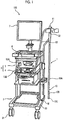
- Fig. 1 is a diagram showing the schematic configuration of an endoscope apparatus 100 that is an embodiment of an endoscope apparatus of the invention.
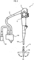
- Fig. 2 is a schematic diagram showing the schematic configuration of an endoscope 1 in the endoscope apparatus 100 shown in Fig. 1 .
- the endoscope apparatus 100 comprises an endoscope 1 and a control device 2 that controls the endoscope 1.
- the control device 2 comprises a processor device 4 and a light source device 5.
- a display unit 7 for displaying a captured image or the like and an input unit 6, which is an interface for inputting various kinds of information to the processor device 4, are connected to the processor device 4.
- the processor device 4 controls the endoscope 1, the light source device 5, and the display unit 7.
- the endoscope 1 comprises: an insertion part 10 that is a tubular member extending in one direction, and is inserted into the body cavity; an operation unit 11 which is provided in a proximal end portion of the insertion part 10 and in which operation members for performing an observation mode switching operation, imaging and recording operations, a forceps operation, an air and water supply operation, a suction operation, an electric scalpel operation, and the like are provided; an angle knob 12 provided adjacent to the operation unit 11; and a universal cord 13 including connector portions 13A and 13B for detachably connecting the endoscope 1 to the light source device 5 and the processor device 4.
- a forceps hole for inserting biopsy forceps as a collection tool for collecting living tissue such as cells or polyps
- a storage hole for storing an electric scalpel and various channels such as air and water supply channels and a suction channel are provided inside the operation unit 11 and the insertion part 10.
- the insertion part 10 is configured to include a flexible portion 10A that has flexibility, a bending portion 10B provided at the distal end of the flexible portion 10A, and a hard distal end portion 10C provided at the distal end of the bending portion 10B.
- the bending portion 10B is configured so as to be able to be bent by the operation of rotating the angle knob 12.
- the bending portion 10B can be bent in any direction and at any angle according to a part or the like of a subject in which the endoscope 1 is used, so that the distal end portion 10C can be directed in a desired direction.
- the control device 2, the input unit 6, and the display unit 7 are housed in a cart unit 3 in which a caster 31 is provided on a lower base 33.
- the cart unit 3 forms a housing unit in which the control device 2 is housed.
- An endoscope holding unit 32 for holding the endoscope 1 by suspending the operation unit 11 of the endoscope 1 is provided in the cart unit 3. With the endoscope 1 in a state of being held by the endoscope holding unit 32, the insertion part 10 always hangs down at the same position. In this state, the distal end portion 10C of the endoscope 1 faces the floor of the endoscope examination room where the cart unit 3 is provided.
- the base 33 of the cart unit 3 is located closer to the floor than the distal end portion 10C of the endoscope 1 held by the endoscope holding unit 32.
- a marker M that is used to identify the state of the endoscope 1, which will be described later, is provided on the base 33 of the cart unit 3.
- the marker M is a seal on which a predetermined mark is printed, a clip on which a predetermined mark is printed, or the like.
- the mark has a shape that cannot be present inside the body cavity of the subject into which the insertion part 10 is inserted.
- Fig. 3 is a schematic diagram showing the internal configuration of the endoscope apparatus 100 shown in Fig. 1 .
- the light source device 5 comprises a light source controller 51 and a light source unit 52.
- the light source unit 52 generates illumination light for irradiating the subject.
- the illumination light emitted from the light source unit 52 is incident on a light guide 20 built in the universal cord 13, and is emitted to the subject through an illumination lens 20a provided in the distal end portion 10C of the insertion part 10.
- a white light source that emits white light or a plurality of light sources including a white light source and light sources that emit light of other colors (for example, a blue light source that emits blue light) are used.
- a plurality of illumination lenses 20a may be provided according to the type of light emitted from the light source unit 52.
- the light source controller 51 includes various processors for performing processing by executing a program, and is connected to a system controller 44 of the processor device 4.
- the light source controller 51 controls the light source unit 52 based on a command from the system controller 44.
- An imaging optical system including an objective lens 21 and a lens group 22, an imaging element 23 for imaging the subject through the imaging optical system, and the light guide 20 for guiding illumination light emitted from the light source unit 52 to the illumination lens 20a are provided in the distal end portion 10C of the endoscope 1.
- the light guide 20 extends from the distal end portion 10C to the connector portion 13A of the universal cord 13. In a state in which the connector portion 13A of the universal cord 13 is connected to the light source device 5, illumination light emitted from the light source unit 52 of the light source device 5 can be incident on the light guide 20.
- the imaging element 23 it is possible to use a charge coupled device (CCD) image sensor, a complementary metal oxide semiconductor (CMOS) image sensor, and the like.
- CCD charge coupled device
- CMOS complementary metal oxide semiconductor
- the imaging element 23 has a light receiving surface on which a plurality of pixels are arranged in a two-dimensional manner, and converts an optical image formed on the light receiving surface by the above-described imaging optical system into an electrical signal (imaging signal) in each pixel and outputs the electrical signal (imaging signal).
- imaging signal an electrical signal
- imaging element 23 for example, one having a color filter of a primary color or a complementary color is used.
- a group of imaging signals output from the respective pixels on the light receiving surface of the imaging element 23 is referred to as a captured image signal.
- the imaging element 23 in which no color filter is mounted may be used.
- An endoscope controller 26 is provided inside the connector portion 13B of the universal cord 13.
- the endoscope controller 26 includes various processors for performing processing by executing a program.
- the endoscope controller 26 is connected to the system controller 44 of the processor device 4 by wiring inside the connector portion 13B.
- the endoscope controller 26 controls the imaging element 23 based on a command from the system controller 44.
- a signal corresponding to an operation (for example, an imaging operation for recording a still image) of the operation unit 11 shown in Fig. 1 is input to the endoscope controller 26.
- the processor device 4 comprises a signal processing unit 42, a display controller 43, and the system controller 44.
- the signal processing unit 42 generates captured image data by receiving and processing the captured image signal output and transmitted from the imaging element 23.
- the captured image data generated by the signal processing unit 42 is recorded on a recording medium, such as a hard disk or a flash memory (not shown).
- the display controller 43 displays, on the display unit 7, a captured image based on the captured image data generated by the signal processing unit 42.
- the system controller 44 controls each unit of the processor device 4, and performs overall control of the endoscope apparatus 100 by sending a command to the endoscope controller 26 of the endoscope 1 and the light source controller 51 of the light source device 5.
- the system controller 44 controls the imaging element 23 through the endoscope controller 26, and controls the light source unit 52 through the light source controller 51.
- the system controller 44 includes various processors for performing processing by executing a program, a random access memory (RAM), and a read only memory (ROM).
- RAM random access memory
- ROM read only memory
- the various processors in this specification include a central processing unit (CPU) that is a general-purpose processor that performs various kinds of processing by executing a program, a programmable logic device (PLD) that is a processor whose circuit configuration can be changed after manufacture, such as a field programmable gate array (FPGA), and a dedicated electric circuit that is a processor having a circuit configuration that is designed for exclusive use in order to execute specific processing, such as an application specific integrated circuit (ASIC).
- CPU central processing unit
- PLD programmable logic device
- FPGA field programmable gate array
- ASIC application specific integrated circuit
- the structure of these various processors is an electric circuit in which circuit elements, such as semiconductor elements, are combined.
- the system controller 44 may be configured by one of various processors, or may be a combination of two or more processors of the same type or different types (for example, a combination of a plurality of FPGAs or a combination of a CPU and an FPGA).
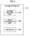
- Fig. 4 is a diagram showing a functional block of the system controller 44 of the processor device 4 shown in Fig. 3 .
- the processor of the system controller 44 functions as a pattern detection unit 44A, a state identification unit 44B, and a controller 44C by executing a program (a program including an endoscope state identification program) stored in the ROM built in the system controller 44.
- the pattern detection unit 44A acquires a captured image signal output from the imaging element 23, and detects a predetermined pattern from the acquired captured image signal.
- the endoscope apparatus 100 is used on the premise that the marker M shown in Fig. 1 is disposed in the imaging range of the imaging element 23 in a state in which the endoscope 1 is held by the endoscope holding unit 32.
- the arrangement position of the marker M does not matter as long as the marker M is within the imaging range of the imaging element 23 in a state in which the endoscope 1 is held by the endoscope holding unit 32.
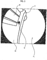
- Fig. 5 is a diagram showing an example of the imaging range of the imaging element 23 in a state in which the endoscope 1 is held by the endoscope holding unit 32.
- a part of the cart unit 3 (a part of the base 33 and a part of an erected portion 34 erected on the base 33) and a part of a floor FL on which the cart unit 3 is provided are present.
- the cart unit 3 and the floor FL form an object in the imaging range.
- Figs. 1 and 5 show an example in which the marker M is disposed on the base 33 of the cart unit 3 in the imaging range.
- the marker M may be disposed at a position of the floor FL in the imaging range, for example, the floor FL facing the distal end portion 10C.
- the pattern detection unit 44A detects the shape of the mark printed on the marker M, as the above pattern, from the captured image signal. For example, an image of the mark printed on the marker M is stored in the ROM of the system controller 44 as a template image. Then, the pattern detection unit 44A determines the presence or absence of the above pattern by performing pattern matching using the template image from the captured image signal.
- the state identification unit 44B recognizes that the endoscope 1 is in a non-use state (a state in which the endoscope 1 is not used). In a case where the above pattern is not detected by the pattern detection unit 44A, the state identification unit 44B recognizes that the endoscope 1 is in a use state (a state in which the endoscope 1 is used).
- the state in which the endoscope 1 is used refers to a state in which the endoscope 1 is detached from the endoscope holding unit 32 so that the endoscope 1 is moved by the user.
- the state in which the endoscope 1 is not used refers to a state in which the endoscope 1 is suspended by the endoscope holding unit 32 so that the endoscope 1 is not moved by the user.
- the controller 44C performs at least one of various controls exemplified in the following (A) to (G).
- A Start emission of illumination light from the light source unit 52.
- B Start recording of a motion picture captured by the imaging element 23.
- C Start a timer that counts various times to be recorded at the time of performing an endoscope examination.
- D In a case where light in the examination room can be remotely controlled, the light is made to be dark.
- E In the case of an examination in which a colon navigation system is used, magnetic field driving of the colon navigation system is started.
- F Display information of an examinee on the display unit 7 for final checking before the examination.
- G Start a water supply or air supply pump.
- the controller 44C may end the various controls shown in the above (A) to (G), for example, due to the user performing an operation on a button provided in the operation unit 11, or may end the various controls shown in the above (A) to (G) in a case where there is a change from the state in which the state identification unit 44B recognizes that the endoscope 1 is in a use state to the state in which the state identification unit 44B recognizes that the endoscope 1 is in a non-use state.
- the above pattern can be detected from the captured image signal output from the imaging element 23, and it is possible to identify whether the endoscope 1 is in a use state or a non-use state according to the presence or absence of the pattern.
- identifying the use state and the non-use state using a parameter indicating the image characteristics, such as the brightness distribution of the captured image signal instead of identifying the use state and the non-use state according to the detection of the pattern, the use state and the non-use state can be accurately identified regardless of the environment in which the endoscope apparatus 100 is placed.
- the use state and the non-use state of the endoscope 1 can be identified simply by providing the marker M exemplified in Figs. 1 and 5 in the cart unit 3 and updating the firmware of the system controller 44. Therefore, it is possible to construct a highly versatile system using the existing endoscope 1. Even in a case where the new endoscope 1 is sold, the endoscope 1 does not require a special mechanism. Therefore, it is possible to prevent an increase in the manufacturing cost of the endoscope 1.
- the marker M is provided in the cart unit 3 and used. Therefore, even in a case where the cart unit 3 is moved to another place, it is possible to identify the use state and the non-use state of the endoscope 1 without changing the position of the marker M.
- the marker M is provided so that one marker M is included in the imaging range shown in Fig. 5 .
- the marker M may be provided so that a plurality of markers M are present in the imaging range.
- the marker M may be provided on each of the base 33 and the floor FL in the imaging range, or the two markers M may be provided on the base 33 in the imaging range.
- the pattern detection unit 44A detects each mark printed on the two markers M from the captured image signal. Then, in a case where both marks are detected, the state identification unit 44B may recognize that the endoscope 1 is in a non-use state.
- the pattern detection unit 44A detects the mark printed on the marker M as the above pattern.
- the pattern to be detected is not limited to the mark.
- the shape of the cart unit 3 (a part of the base 33 and a part of the erected portion 34) in the imaging range shown in Fig. 5 may be the above pattern.
- the marker M since the marker M is not necessary, it is possible to reduce the manufacturing cost, the delivery cost, and the like of the marker M.
- the cart unit 3 even in a case where the cart unit 3 is moved to another place, it is possible to identify the use state and the non-use state of the endoscope 1.
- both the shape of the cart unit 3 in the imaging range shown in Fig. 5 and the mark printed on the marker M may be the above pattern. In this manner, it can be recognized with higher accuracy that the endoscope 1 is in a non-use state.
Landscapes
- Health & Medical Sciences (AREA)
- Life Sciences & Earth Sciences (AREA)
- Surgery (AREA)
- Engineering & Computer Science (AREA)
- Molecular Biology (AREA)
- Public Health (AREA)
- Veterinary Medicine (AREA)
- Biomedical Technology (AREA)
- Heart & Thoracic Surgery (AREA)
- Medical Informatics (AREA)
- Nuclear Medicine, Radiotherapy & Molecular Imaging (AREA)
- Animal Behavior & Ethology (AREA)
- General Health & Medical Sciences (AREA)
- Pathology (AREA)
- Oral & Maxillofacial Surgery (AREA)
- Signal Processing (AREA)
- Physics & Mathematics (AREA)
- Biophysics (AREA)
- Optics & Photonics (AREA)
- Radiology & Medical Imaging (AREA)
- Endoscopes (AREA)
Claims (7)
- Endoskopvorrichtung (100), umfassend:ein Endoskop (1), das ein Bildgebungselement (23) enthält, undeine Steuereinrichtung (2) für das Endoskop, welche konfiguriert ist zur Aufnahme in einer Gehäuseeinheit (3) und aufweist:wobei in einem Zustand, in welchem das Endoskop (1) von einer Endoskophalteeinheit (32) zum Halten des in der Gehäuseeinheit (3) vorhandenen Endoskops gehalten wird, das detektierte Muster (i) eine Form einer Markierung (M) aufweist, die sich an einem in einem Bildbereich des Bildgebungselements (23) befindlichen Objekt befindet, und/oder (ii) eine Form der in dem Bildbereich vorhandenen Gehäuseeinheit ist.eine Musterdetektoreinheit (44A), konfiguriert zum Erfassen eines aufgenommenen Bildsignals, das von dem in dem Endoskop (1) enthaltenen Bildgebungselement (23) ausgegeben wird, und konfiguriert ist zum Detektieren eines vorbestimmten Musters aus dem aufgenommenen Bildsignal; undeine Zustandsidentifikationseinheit (44B), konfiguriert zum Erkennen, dass sich das Endoskop (1) in einem Nicht-Gebrauchszustand befindet, falls das Muster detektiert wird und konfiguriert ist zum Erkennen, dass das Endoskop (1) sich in einem Gebrauchszustand befindet, falls das Muster nicht detektiert wird;
- Steuereinrichtung für ein Endoskop nach Anspruch 1,
bei der das detektierte Muster eine Form einer ersten Markierung (M) ist, die sich auf einem Teil der Gehäuseeinheit befindet. - Steuereinrichtung für ein Endoskop nach Anspruch 1 oder 2,
bei der das detektierte Muster eine Form einer zweiten Markierung (M) ist, die sich auf einem Boden befindet, auf dem die Gehäuseeinheit positioniert ist. - Verfahren zum Identifizieren eines Zustands eines Endoskops einer Endoskopvorrichtung (100), die eine Steuereinrichtung (2) enthält, welche konfiguriert ist zur Aufnahme in einer Gehäuseeinheit (3), umfassend:einen Musterdetektierschritt des Erfassens eines aufgenommenen Bildsignals, das von einem in dem Endoskop (1) enthaltenen Bildgebungselement (23) ausgegeben wird, und des Detektierens eines vorbestimmten Musters aus dem aufgenommenen Bildsignals; undeinen Zustandsidentifikationsschritt des Erkennens, dass sich das Endoskop in einem Nicht-Gebrauszustand befindet, falls das Muster detektiert wird, und des Erkennens, dass sich das Endoskop (1) in einem Gebrauchszustand befindet, falls das Muster nicht detektiert wird,wobei in einem Zustand, in welchem das Endoskop (1) von einer zum Halten des in der Gehäuseeinheit vorhandenen Endoskops (1) den in der Endoskophalteeinheit (32) gehalten wird, das Muster (i) eine Form einer Markierung (M) ist, die sich an dem in einem Bildgebungsbereich des Bildgebungselements (23) befindlichen Objekt befindet, und/oder (ii) eine Form der Gehäuseeinheit ist, die sich in dem Bildbereich befindet.
- Verfahren zum Identifizieren eines Zustands eines Endoskops nach Anspruch 4,
bei dem das detektierte Muster eine Form einer ersten Markierung (M) ist, die sich auf einem Teil der Gehäuseeinheit befindet. - Verfahren zum Identifizieren eines Zustands eines Endoskops nach Anspruch 4 oder 5,
bei dem das detektierte Muster eine Form einer zweiten Markierung (M) ist, die sich auf einem Boden befindet, auf dem die Gehäuseeinheit positioniert ist. - Nicht-flüchtiges computer-lesbares Aufzeichnungsmedium, das ein Programm zum Identifizieren eines Zustands eines Endoskops einer Endoskopvorrichtung (100) speichert, das eine Steuereinrichtung (2) enthält, die konfiguriert ist zur Aufnahme in einer Gehäuseeinheit (3), wobei das Programm einen Computer veranlasst, folgendes auszuführen:einen Musterdetektierschritt des Erfassens eines aufgenommenen Bildsignals, das von einem in dem Endoskop (1) enthaltenen Bildgebungselement (23) ausgegeben wird, und des Detektierens eines vorbestimmten Musters aus dem aufgenommenen Bildsignals; undeinen Zustandsidentifikationsschritt des Erkennens, dass sich das Endoskop (1) in einem Nicht-Gebrauszustand befindet, falls das Muster detektiert wird, und des Erkennens, dass sich das Endoskop (1) in einem Gebrauchszustand befindet, falls das Muster nicht detektiert wird,wobei in einem Zustand, in welchem das Endoskop (1) von einer zum Halten des in der Gehäuseeinheit vorhandenen Endoskops (1) den in der Endoskophalteeinheit (32) gehalten wird, das Muster (i) eine Form einer Markierung (M) ist, die sich an dem in einem Bildgebungsbereich des Bildgebungselements (23) befindlichen Objekt befindet, und/oder (ii) eine Form der Gehäuseeinheit ist, die sich in dem Bildbereich befindet.
Applications Claiming Priority (1)
| Application Number | Priority Date | Filing Date | Title |
|---|---|---|---|
| JP2018153132A JP6957424B2 (ja) | 2018-08-16 | 2018-08-16 | 内視鏡の制御装置、内視鏡装置、内視鏡の状態識別方法、内視鏡の状態識別プログラム |
Publications (2)
| Publication Number | Publication Date |
|---|---|
| EP3610771A1 EP3610771A1 (de) | 2020-02-19 |
| EP3610771B1 true EP3610771B1 (de) | 2021-09-15 |
Family
ID=66676270
Family Applications (1)
| Application Number | Title | Priority Date | Filing Date |
|---|---|---|---|
| EP19177101.3A Active EP3610771B1 (de) | 2018-08-16 | 2019-05-28 | Steuerungsgerät für ein endoskop mit mitteln zur erkennung eines musters und zur feststellung, ob das endoskop in einem nicht-in-betriebszustand oder in einem in-betriebszustand ist und ein zugehöriges verfahren und ein programm |
Country Status (2)
| Country | Link |
|---|---|
| EP (1) | EP3610771B1 (de) |
| JP (1) | JP6957424B2 (de) |
Family Cites Families (8)
| Publication number | Priority date | Publication date | Assignee | Title |
|---|---|---|---|---|
| JPH01303122A (ja) | 1988-06-01 | 1989-12-07 | Toshiba Corp | 電子内視鏡装置 |
| US6675040B1 (en) * | 1991-01-28 | 2004-01-06 | Sherwood Services Ag | Optical object tracking system |
| JP2000189383A (ja) | 1998-12-25 | 2000-07-11 | Olympus Optical Co Ltd | 内視鏡装置 |
| DE102009043652A1 (de) | 2009-09-29 | 2011-03-31 | Richard Wolf Gmbh | Endoskopisches Instrument |
| CN102834043B (zh) * | 2010-09-14 | 2015-07-01 | 奥林巴斯医疗株式会社 | 内窥镜系统和视野不良判定方法 |
| JP5752945B2 (ja) * | 2011-01-24 | 2015-07-22 | オリンパス株式会社 | 内視鏡システム |
| JP6153414B2 (ja) * | 2013-08-06 | 2017-06-28 | オリンパス株式会社 | 挿入システム及び形状センサの形状検出特性を調整する方法 |
| JPWO2017010486A1 (ja) * | 2015-07-14 | 2018-04-26 | オリンパス株式会社 | 血管認識システム |
-
2018
- 2018-08-16 JP JP2018153132A patent/JP6957424B2/ja active Active
-
2019
- 2019-05-28 EP EP19177101.3A patent/EP3610771B1/de active Active
Also Published As
| Publication number | Publication date |
|---|---|
| JP2020025800A (ja) | 2020-02-20 |
| EP3610771A1 (de) | 2020-02-19 |
| JP6957424B2 (ja) | 2021-11-02 |
Similar Documents
| Publication | Publication Date | Title |
|---|---|---|
| US20230086972A1 (en) | Medical image processing device, endoscope system, medical image processing method, and program | |
| US12059126B2 (en) | Endoscope system | |
| US11536556B2 (en) | Measurement support device, endoscope system, processor for endoscope system, and measurement support method for measuring object size | |
| JP6957771B2 (ja) | 内視鏡システム、及び、内視鏡用画像処理方法、並びに、内視鏡用画像処理プログラム | |
| JP6177458B2 (ja) | 画像処理装置及び内視鏡システム | |
| US7995798B2 (en) | Device, system and method for estimating the size of an object in a body lumen | |
| JP6064106B1 (ja) | 画像処理装置、カプセル型内視鏡システム、及び内視鏡システム | |
| CN111295127B (zh) | 检查支持装置、内窥镜装置及记录介质 | |
| US11490785B2 (en) | Measurement support device, endoscope system, and processor measuring size of subject using measurement auxiliary light | |
| CN110418596A (zh) | 测量辅助装置、内窥镜系统及处理器 | |
| CN112969402B (zh) | 内窥镜系统以及用于内窥镜系统的图像处理装置和图像处理方法 | |
| JP6644899B2 (ja) | 計測支援装置、内視鏡システム、及び内視鏡システムのプロセッサ | |
| JP6987243B2 (ja) | ランドマーク推定方法、内視鏡装置、及び、位置推定プログラム | |
| CN117042669A (zh) | 内窥镜处理器、内窥镜装置以及诊断用图像显示方法 | |
| US20160331216A1 (en) | Endoscope device | |
| US20240185597A1 (en) | Endoscopic device, method for verifying an identity of a component of an endoscopic device, and computer program product | |
| KR20200021708A (ko) | 가시광 및 근적외선 광을 모두 가시화할 수 있는 내시경 장치 | |
| JP6967493B2 (ja) | 内視鏡の制御装置、内視鏡装置、内視鏡の状態識別方法、内視鏡の状態識別プログラム | |
| CN113631076B (zh) | 内窥镜用处理器装置、医疗图像处理装置及其工作方法以及计算机可读介质 | |
| US8979737B2 (en) | Control apparatus, bio-optical measurement apparatus and endoscope system | |
| CN114554937A (zh) | 内窥镜系统、控制程序及显示方法 | |
| EP3610771B1 (de) | Steuerungsgerät für ein endoskop mit mitteln zur erkennung eines musters und zur feststellung, ob das endoskop in einem nicht-in-betriebszustand oder in einem in-betriebszustand ist und ein zugehöriges verfahren und ein programm | |
| CN110799081A (zh) | 内窥镜装置及测量支持方法 | |
| KR100907487B1 (ko) | 내시경 장치 및 이를 이용한 진단 시스템 | |
| CN111989026B (zh) | 内窥镜装置、内窥镜装置的工作方法及记录介质 |
Legal Events
| Date | Code | Title | Description |
|---|---|---|---|
| PUAI | Public reference made under article 153(3) epc to a published international application that has entered the european phase |
Free format text: ORIGINAL CODE: 0009012 |
|
| STAA | Information on the status of an ep patent application or granted ep patent |
Free format text: STATUS: THE APPLICATION HAS BEEN PUBLISHED |
|
| AK | Designated contracting states |
Kind code of ref document: A1 Designated state(s): AL AT BE BG CH CY CZ DE DK EE ES FI FR GB GR HR HU IE IS IT LI LT LU LV MC MK MT NL NO PL PT RO RS SE SI SK SM TR |
|
| AX | Request for extension of the european patent |
Extension state: BA ME |
|
| STAA | Information on the status of an ep patent application or granted ep patent |
Free format text: STATUS: REQUEST FOR EXAMINATION WAS MADE |
|
| 17P | Request for examination filed |
Effective date: 20200507 |
|
| RBV | Designated contracting states (corrected) |
Designated state(s): AL AT BE BG CH CY CZ DE DK EE ES FI FR GB GR HR HU IE IS IT LI LT LU LV MC MK MT NL NO PL PT RO RS SE SI SK SM TR |
|
| RIC1 | Information provided on ipc code assigned before grant |
Ipc: A61B 90/90 20160101ALI20201223BHEP Ipc: A61B 90/00 20160101ALI20201223BHEP Ipc: A61B 1/00 20060101AFI20201223BHEP Ipc: A61B 90/94 20160101ALI20201223BHEP |
|
| GRAP | Despatch of communication of intention to grant a patent |
Free format text: ORIGINAL CODE: EPIDOSNIGR1 |
|
| STAA | Information on the status of an ep patent application or granted ep patent |
Free format text: STATUS: GRANT OF PATENT IS INTENDED |
|
| INTG | Intention to grant announced |
Effective date: 20210217 |
|
| GRAJ | Information related to disapproval of communication of intention to grant by the applicant or resumption of examination proceedings by the epo deleted |
Free format text: ORIGINAL CODE: EPIDOSDIGR1 |
|
| STAA | Information on the status of an ep patent application or granted ep patent |
Free format text: STATUS: REQUEST FOR EXAMINATION WAS MADE |
|
| RAP3 | Party data changed (applicant data changed or rights of an application transferred) |
Owner name: FUJIFILM CORPORATION |
|
| INTC | Intention to grant announced (deleted) | ||
| GRAP | Despatch of communication of intention to grant a patent |
Free format text: ORIGINAL CODE: EPIDOSNIGR1 |
|
| STAA | Information on the status of an ep patent application or granted ep patent |
Free format text: STATUS: GRANT OF PATENT IS INTENDED |
|
| INTG | Intention to grant announced |
Effective date: 20210527 |
|
| GRAS | Grant fee paid |
Free format text: ORIGINAL CODE: EPIDOSNIGR3 |
|
| GRAA | (expected) grant |
Free format text: ORIGINAL CODE: 0009210 |
|
| STAA | Information on the status of an ep patent application or granted ep patent |
Free format text: STATUS: THE PATENT HAS BEEN GRANTED |
|
| AK | Designated contracting states |
Kind code of ref document: B1 Designated state(s): AL AT BE BG CH CY CZ DE DK EE ES FI FR GB GR HR HU IE IS IT LI LT LU LV MC MK MT NL NO PL PT RO RS SE SI SK SM TR |
|
| REG | Reference to a national code |
Ref country code: CH Ref legal event code: EP |
|
| REG | Reference to a national code |
Ref country code: DE Ref legal event code: R096 Ref document number: 602019007654 Country of ref document: DE |
|
| REG | Reference to a national code |
Ref country code: IE Ref legal event code: FG4D |
|
| REG | Reference to a national code |
Ref country code: AT Ref legal event code: REF Ref document number: 1429869 Country of ref document: AT Kind code of ref document: T Effective date: 20211015 |
|
| REG | Reference to a national code |
Ref country code: LT Ref legal event code: MG9D |
|
| REG | Reference to a national code |
Ref country code: NL Ref legal event code: MP Effective date: 20210915 |
|
| PG25 | Lapsed in a contracting state [announced via postgrant information from national office to epo] |
Ref country code: BG Free format text: LAPSE BECAUSE OF FAILURE TO SUBMIT A TRANSLATION OF THE DESCRIPTION OR TO PAY THE FEE WITHIN THE PRESCRIBED TIME-LIMIT Effective date: 20211215 Ref country code: LT Free format text: LAPSE BECAUSE OF FAILURE TO SUBMIT A TRANSLATION OF THE DESCRIPTION OR TO PAY THE FEE WITHIN THE PRESCRIBED TIME-LIMIT Effective date: 20210915 Ref country code: HR Free format text: LAPSE BECAUSE OF FAILURE TO SUBMIT A TRANSLATION OF THE DESCRIPTION OR TO PAY THE FEE WITHIN THE PRESCRIBED TIME-LIMIT Effective date: 20210915 Ref country code: NO Free format text: LAPSE BECAUSE OF FAILURE TO SUBMIT A TRANSLATION OF THE DESCRIPTION OR TO PAY THE FEE WITHIN THE PRESCRIBED TIME-LIMIT Effective date: 20211215 Ref country code: FI Free format text: LAPSE BECAUSE OF FAILURE TO SUBMIT A TRANSLATION OF THE DESCRIPTION OR TO PAY THE FEE WITHIN THE PRESCRIBED TIME-LIMIT Effective date: 20210915 Ref country code: RS Free format text: LAPSE BECAUSE OF FAILURE TO SUBMIT A TRANSLATION OF THE DESCRIPTION OR TO PAY THE FEE WITHIN THE PRESCRIBED TIME-LIMIT Effective date: 20210915 Ref country code: SE Free format text: LAPSE BECAUSE OF FAILURE TO SUBMIT A TRANSLATION OF THE DESCRIPTION OR TO PAY THE FEE WITHIN THE PRESCRIBED TIME-LIMIT Effective date: 20210915 |
|
| REG | Reference to a national code |
Ref country code: AT Ref legal event code: MK05 Ref document number: 1429869 Country of ref document: AT Kind code of ref document: T Effective date: 20210915 |
|
| PG25 | Lapsed in a contracting state [announced via postgrant information from national office to epo] |
Ref country code: LV Free format text: LAPSE BECAUSE OF FAILURE TO SUBMIT A TRANSLATION OF THE DESCRIPTION OR TO PAY THE FEE WITHIN THE PRESCRIBED TIME-LIMIT Effective date: 20210915 Ref country code: GR Free format text: LAPSE BECAUSE OF FAILURE TO SUBMIT A TRANSLATION OF THE DESCRIPTION OR TO PAY THE FEE WITHIN THE PRESCRIBED TIME-LIMIT Effective date: 20211216 |
|
| PG25 | Lapsed in a contracting state [announced via postgrant information from national office to epo] |
Ref country code: AT Free format text: LAPSE BECAUSE OF FAILURE TO SUBMIT A TRANSLATION OF THE DESCRIPTION OR TO PAY THE FEE WITHIN THE PRESCRIBED TIME-LIMIT Effective date: 20210915 |
|
| PG25 | Lapsed in a contracting state [announced via postgrant information from national office to epo] |
Ref country code: IS Free format text: LAPSE BECAUSE OF FAILURE TO SUBMIT A TRANSLATION OF THE DESCRIPTION OR TO PAY THE FEE WITHIN THE PRESCRIBED TIME-LIMIT Effective date: 20220115 Ref country code: SM Free format text: LAPSE BECAUSE OF FAILURE TO SUBMIT A TRANSLATION OF THE DESCRIPTION OR TO PAY THE FEE WITHIN THE PRESCRIBED TIME-LIMIT Effective date: 20210915 Ref country code: SK Free format text: LAPSE BECAUSE OF FAILURE TO SUBMIT A TRANSLATION OF THE DESCRIPTION OR TO PAY THE FEE WITHIN THE PRESCRIBED TIME-LIMIT Effective date: 20210915 Ref country code: RO Free format text: LAPSE BECAUSE OF FAILURE TO SUBMIT A TRANSLATION OF THE DESCRIPTION OR TO PAY THE FEE WITHIN THE PRESCRIBED TIME-LIMIT Effective date: 20210915 Ref country code: PT Free format text: LAPSE BECAUSE OF FAILURE TO SUBMIT A TRANSLATION OF THE DESCRIPTION OR TO PAY THE FEE WITHIN THE PRESCRIBED TIME-LIMIT Effective date: 20220117 Ref country code: PL Free format text: LAPSE BECAUSE OF FAILURE TO SUBMIT A TRANSLATION OF THE DESCRIPTION OR TO PAY THE FEE WITHIN THE PRESCRIBED TIME-LIMIT Effective date: 20210915 Ref country code: NL Free format text: LAPSE BECAUSE OF FAILURE TO SUBMIT A TRANSLATION OF THE DESCRIPTION OR TO PAY THE FEE WITHIN THE PRESCRIBED TIME-LIMIT Effective date: 20210915 Ref country code: ES Free format text: LAPSE BECAUSE OF FAILURE TO SUBMIT A TRANSLATION OF THE DESCRIPTION OR TO PAY THE FEE WITHIN THE PRESCRIBED TIME-LIMIT Effective date: 20210915 Ref country code: EE Free format text: LAPSE BECAUSE OF FAILURE TO SUBMIT A TRANSLATION OF THE DESCRIPTION OR TO PAY THE FEE WITHIN THE PRESCRIBED TIME-LIMIT Effective date: 20210915 Ref country code: CZ Free format text: LAPSE BECAUSE OF FAILURE TO SUBMIT A TRANSLATION OF THE DESCRIPTION OR TO PAY THE FEE WITHIN THE PRESCRIBED TIME-LIMIT Effective date: 20210915 Ref country code: AL Free format text: LAPSE BECAUSE OF FAILURE TO SUBMIT A TRANSLATION OF THE DESCRIPTION OR TO PAY THE FEE WITHIN THE PRESCRIBED TIME-LIMIT Effective date: 20210915 |
|
| REG | Reference to a national code |
Ref country code: DE Ref legal event code: R097 Ref document number: 602019007654 Country of ref document: DE |
|
| PLBE | No opposition filed within time limit |
Free format text: ORIGINAL CODE: 0009261 |
|
| STAA | Information on the status of an ep patent application or granted ep patent |
Free format text: STATUS: NO OPPOSITION FILED WITHIN TIME LIMIT |
|
| PG25 | Lapsed in a contracting state [announced via postgrant information from national office to epo] |
Ref country code: DK Free format text: LAPSE BECAUSE OF FAILURE TO SUBMIT A TRANSLATION OF THE DESCRIPTION OR TO PAY THE FEE WITHIN THE PRESCRIBED TIME-LIMIT Effective date: 20210915 |
|
| 26N | No opposition filed |
Effective date: 20220616 |
|
| PG25 | Lapsed in a contracting state [announced via postgrant information from national office to epo] |
Ref country code: SI Free format text: LAPSE BECAUSE OF FAILURE TO SUBMIT A TRANSLATION OF THE DESCRIPTION OR TO PAY THE FEE WITHIN THE PRESCRIBED TIME-LIMIT Effective date: 20210915 |
|
| REG | Reference to a national code |
Ref country code: CH Ref legal event code: PL |
|
| REG | Reference to a national code |
Ref country code: BE Ref legal event code: MM Effective date: 20220531 |
|
| PG25 | Lapsed in a contracting state [announced via postgrant information from national office to epo] |
Ref country code: MC Free format text: LAPSE BECAUSE OF FAILURE TO SUBMIT A TRANSLATION OF THE DESCRIPTION OR TO PAY THE FEE WITHIN THE PRESCRIBED TIME-LIMIT Effective date: 20210915 Ref country code: LU Free format text: LAPSE BECAUSE OF NON-PAYMENT OF DUE FEES Effective date: 20220528 Ref country code: LI Free format text: LAPSE BECAUSE OF NON-PAYMENT OF DUE FEES Effective date: 20220531 Ref country code: IT Free format text: LAPSE BECAUSE OF FAILURE TO SUBMIT A TRANSLATION OF THE DESCRIPTION OR TO PAY THE FEE WITHIN THE PRESCRIBED TIME-LIMIT Effective date: 20210915 Ref country code: CH Free format text: LAPSE BECAUSE OF NON-PAYMENT OF DUE FEES Effective date: 20220531 |
|
| PG25 | Lapsed in a contracting state [announced via postgrant information from national office to epo] |
Ref country code: IE Free format text: LAPSE BECAUSE OF NON-PAYMENT OF DUE FEES Effective date: 20220528 Ref country code: FR Free format text: LAPSE BECAUSE OF NON-PAYMENT OF DUE FEES Effective date: 20220531 |
|
| PG25 | Lapsed in a contracting state [announced via postgrant information from national office to epo] |
Ref country code: BE Free format text: LAPSE BECAUSE OF NON-PAYMENT OF DUE FEES Effective date: 20220531 |
|
| P01 | Opt-out of the competence of the unified patent court (upc) registered |
Effective date: 20230515 |
|
| GBPC | Gb: european patent ceased through non-payment of renewal fee |
Effective date: 20230528 |
|
| PG25 | Lapsed in a contracting state [announced via postgrant information from national office to epo] |
Ref country code: MK Free format text: LAPSE BECAUSE OF FAILURE TO SUBMIT A TRANSLATION OF THE DESCRIPTION OR TO PAY THE FEE WITHIN THE PRESCRIBED TIME-LIMIT Effective date: 20210915 Ref country code: CY Free format text: LAPSE BECAUSE OF FAILURE TO SUBMIT A TRANSLATION OF THE DESCRIPTION OR TO PAY THE FEE WITHIN THE PRESCRIBED TIME-LIMIT Effective date: 20210915 Ref country code: GB Free format text: LAPSE BECAUSE OF NON-PAYMENT OF DUE FEES Effective date: 20230528 |
|
| PG25 | Lapsed in a contracting state [announced via postgrant information from national office to epo] |
Ref country code: HU Free format text: LAPSE BECAUSE OF FAILURE TO SUBMIT A TRANSLATION OF THE DESCRIPTION OR TO PAY THE FEE WITHIN THE PRESCRIBED TIME-LIMIT; INVALID AB INITIO Effective date: 20190528 |
|
| PG25 | Lapsed in a contracting state [announced via postgrant information from national office to epo] |
Ref country code: MT Free format text: LAPSE BECAUSE OF FAILURE TO SUBMIT A TRANSLATION OF THE DESCRIPTION OR TO PAY THE FEE WITHIN THE PRESCRIBED TIME-LIMIT Effective date: 20210915 |
|
| PGFP | Annual fee paid to national office [announced via postgrant information from national office to epo] |
Ref country code: DE Payment date: 20250402 Year of fee payment: 7 |
|
| PG25 | Lapsed in a contracting state [announced via postgrant information from national office to epo] |
Ref country code: TR Free format text: LAPSE BECAUSE OF FAILURE TO SUBMIT A TRANSLATION OF THE DESCRIPTION OR TO PAY THE FEE WITHIN THE PRESCRIBED TIME-LIMIT Effective date: 20210915 |