EP3610151B1 - Verfahren zum betrieb einer wasserkraftanlage zur regelung der netzfrequenz - Google Patents
Verfahren zum betrieb einer wasserkraftanlage zur regelung der netzfrequenz Download PDFInfo
- Publication number
- EP3610151B1 EP3610151B1 EP18715013.1A EP18715013A EP3610151B1 EP 3610151 B1 EP3610151 B1 EP 3610151B1 EP 18715013 A EP18715013 A EP 18715013A EP 3610151 B1 EP3610151 B1 EP 3610151B1
- Authority
- EP
- European Patent Office
- Prior art keywords
- turbine
- frequency converter
- asynchronous machine
- pump
- water tank
- Prior art date
- Legal status (The legal status is an assumption and is not a legal conclusion. Google has not performed a legal analysis and makes no representation as to the accuracy of the status listed.)
- Active
Links
Images

Classifications
-
- F—MECHANICAL ENGINEERING; LIGHTING; HEATING; WEAPONS; BLASTING
- F03—MACHINES OR ENGINES FOR LIQUIDS; WIND, SPRING, OR WEIGHT MOTORS; PRODUCING MECHANICAL POWER OR A REACTIVE PROPULSIVE THRUST, NOT OTHERWISE PROVIDED FOR
- F03B—MACHINES OR ENGINES FOR LIQUIDS
- F03B13/00—Adaptations of machines or engines for special use; Combinations of machines or engines with driving or driven apparatus; Power stations or aggregates
- F03B13/06—Stations or aggregates of water-storage type, e.g. comprising a turbine and a pump
-
- F—MECHANICAL ENGINEERING; LIGHTING; HEATING; WEAPONS; BLASTING
- F03—MACHINES OR ENGINES FOR LIQUIDS; WIND, SPRING, OR WEIGHT MOTORS; PRODUCING MECHANICAL POWER OR A REACTIVE PROPULSIVE THRUST, NOT OTHERWISE PROVIDED FOR
- F03B—MACHINES OR ENGINES FOR LIQUIDS
- F03B13/00—Adaptations of machines or engines for special use; Combinations of machines or engines with driving or driven apparatus; Power stations or aggregates
- F03B13/08—Machine or engine aggregates in dams or the like; Conduits therefor, e.g. diffusors
-
- H—ELECTRICITY
- H02—GENERATION; CONVERSION OR DISTRIBUTION OF ELECTRIC POWER
- H02J—ELECTRIC POWER NETWORKS; CIRCUIT ARRANGEMENTS OR SYSTEMS FOR SUPPLYING OR DISTRIBUTING ELECTRIC POWER; SYSTEMS FOR STORING ELECTRIC ENERGY
- H02J3/00—Circuit arrangements for AC mains or AC distribution networks
- H02J3/28—Arrangements for balancing of the load in networks by storage of energy
-
- H—ELECTRICITY
- H02—GENERATION; CONVERSION OR DISTRIBUTION OF ELECTRIC POWER
- H02J—ELECTRIC POWER NETWORKS; CIRCUIT ARRANGEMENTS OR SYSTEMS FOR SUPPLYING OR DISTRIBUTING ELECTRIC POWER; SYSTEMS FOR STORING ELECTRIC ENERGY
- H02J3/00—Circuit arrangements for AC mains or AC distribution networks
- H02J3/38—Arrangements for feeding a single network from two or more generators or sources in parallel; Arrangements for feeding already energised networks from additional generators or sources in parallel
- H02J3/381—Dispersed generators
-
- H—ELECTRICITY
- H02—GENERATION; CONVERSION OR DISTRIBUTION OF ELECTRIC POWER
- H02J—ELECTRIC POWER NETWORKS; CIRCUIT ARRANGEMENTS OR SYSTEMS FOR SUPPLYING OR DISTRIBUTING ELECTRIC POWER; SYSTEMS FOR STORING ELECTRIC ENERGY
- H02J3/00—Circuit arrangements for AC mains or AC distribution networks
- H02J3/38—Arrangements for feeding a single network from two or more generators or sources in parallel; Arrangements for feeding already energised networks from additional generators or sources in parallel
- H02J3/46—Controlling the sharing of generated power between the generators, sources or networks
-
- H—ELECTRICITY
- H02—GENERATION; CONVERSION OR DISTRIBUTION OF ELECTRIC POWER
- H02J—ELECTRIC POWER NETWORKS; CIRCUIT ARRANGEMENTS OR SYSTEMS FOR SUPPLYING OR DISTRIBUTING ELECTRIC POWER; SYSTEMS FOR STORING ELECTRIC ENERGY
- H02J3/00—Circuit arrangements for AC mains or AC distribution networks
- H02J3/38—Arrangements for feeding a single network from two or more generators or sources in parallel; Arrangements for feeding already energised networks from additional generators or sources in parallel
- H02J3/46—Controlling the sharing of generated power between the generators, sources or networks
- H02J3/48—Controlling the sharing of active power
-
- H—ELECTRICITY
- H02—GENERATION; CONVERSION OR DISTRIBUTION OF ELECTRIC POWER
- H02K—DYNAMO-ELECTRIC MACHINES
- H02K7/00—Arrangements for handling mechanical energy structurally associated with dynamo-electric machines, e.g. structural association with mechanical driving motors or auxiliary dynamo-electric machines
- H02K7/18—Structural association of electric generators with mechanical driving motors, e.g. with turbines
-
- H—ELECTRICITY
- H02—GENERATION; CONVERSION OR DISTRIBUTION OF ELECTRIC POWER
- H02K—DYNAMO-ELECTRIC MACHINES
- H02K7/00—Arrangements for handling mechanical energy structurally associated with dynamo-electric machines, e.g. structural association with mechanical driving motors or auxiliary dynamo-electric machines
- H02K7/18—Structural association of electric generators with mechanical driving motors, e.g. with turbines
- H02K7/1807—Rotary generators
- H02K7/1823—Rotary generators structurally associated with turbines or similar engines
-
- H—ELECTRICITY
- H02—GENERATION; CONVERSION OR DISTRIBUTION OF ELECTRIC POWER
- H02P—CONTROL OR REGULATION OF ELECTRIC MOTORS, ELECTRIC GENERATORS OR DYNAMO-ELECTRIC CONVERTERS; CONTROLLING TRANSFORMERS, REACTORS OR CHOKE COILS
- H02P9/00—Arrangements for controlling electric generators for the purpose of obtaining a desired output
- H02P9/02—Details of the control
-
- F—MECHANICAL ENGINEERING; LIGHTING; HEATING; WEAPONS; BLASTING
- F05—INDEXING SCHEMES RELATING TO ENGINES OR PUMPS IN VARIOUS SUBCLASSES OF CLASSES F01-F04
- F05B—INDEXING SCHEME RELATING TO WIND, SPRING, WEIGHT, INERTIA OR LIKE MOTORS, TO MACHINES OR ENGINES FOR LIQUIDS COVERED BY SUBCLASSES F03B, F03D AND F03G
- F05B2220/00—Application
- F05B2220/70—Application in combination with
- F05B2220/706—Application in combination with an electrical generator
- F05B2220/7064—Application in combination with an electrical generator of the alternating current (A.C.) type
- F05B2220/70644—Application in combination with an electrical generator of the alternating current (A.C.) type of the asynchronous type, i.e. induction type
- F05B2220/70646—Double fed induction generators (DFIGs)
-
- H—ELECTRICITY
- H02—GENERATION; CONVERSION OR DISTRIBUTION OF ELECTRIC POWER
- H02J—ELECTRIC POWER NETWORKS; CIRCUIT ARRANGEMENTS OR SYSTEMS FOR SUPPLYING OR DISTRIBUTING ELECTRIC POWER; SYSTEMS FOR STORING ELECTRIC ENERGY
- H02J2101/00—Supply or distribution of decentralised, dispersed or local electric power generation
- H02J2101/20—Dispersed power generation using renewable energy sources
-
- Y—GENERAL TAGGING OF NEW TECHNOLOGICAL DEVELOPMENTS; GENERAL TAGGING OF CROSS-SECTIONAL TECHNOLOGIES SPANNING OVER SEVERAL SECTIONS OF THE IPC; TECHNICAL SUBJECTS COVERED BY FORMER USPC CROSS-REFERENCE ART COLLECTIONS [XRACs] AND DIGESTS
- Y02—TECHNOLOGIES OR APPLICATIONS FOR MITIGATION OR ADAPTATION AGAINST CLIMATE CHANGE
- Y02E—REDUCTION OF GREENHOUSE GAS [GHG] EMISSIONS, RELATED TO ENERGY GENERATION, TRANSMISSION OR DISTRIBUTION
- Y02E10/00—Energy generation through renewable energy sources
- Y02E10/20—Hydro energy
-
- Y—GENERAL TAGGING OF NEW TECHNOLOGICAL DEVELOPMENTS; GENERAL TAGGING OF CROSS-SECTIONAL TECHNOLOGIES SPANNING OVER SEVERAL SECTIONS OF THE IPC; TECHNICAL SUBJECTS COVERED BY FORMER USPC CROSS-REFERENCE ART COLLECTIONS [XRACs] AND DIGESTS
- Y02—TECHNOLOGIES OR APPLICATIONS FOR MITIGATION OR ADAPTATION AGAINST CLIMATE CHANGE
- Y02E—REDUCTION OF GREENHOUSE GAS [GHG] EMISSIONS, RELATED TO ENERGY GENERATION, TRANSMISSION OR DISTRIBUTION
- Y02E60/00—Enabling technologies; Technologies with a potential or indirect contribution to GHG emissions mitigation
- Y02E60/16—Mechanical energy storage, e.g. flywheels or pressurised fluids
-
- Y—GENERAL TAGGING OF NEW TECHNOLOGICAL DEVELOPMENTS; GENERAL TAGGING OF CROSS-SECTIONAL TECHNOLOGIES SPANNING OVER SEVERAL SECTIONS OF THE IPC; TECHNICAL SUBJECTS COVERED BY FORMER USPC CROSS-REFERENCE ART COLLECTIONS [XRACs] AND DIGESTS
- Y02—TECHNOLOGIES OR APPLICATIONS FOR MITIGATION OR ADAPTATION AGAINST CLIMATE CHANGE
- Y02E—REDUCTION OF GREENHOUSE GAS [GHG] EMISSIONS, RELATED TO ENERGY GENERATION, TRANSMISSION OR DISTRIBUTION
- Y02E70/00—Other energy conversion or management systems reducing GHG emissions
- Y02E70/30—Systems combining energy storage with energy generation of non-fossil origin
Definitions
- the present invention relates to a hydropower plant which is suitable for rapidly regulating the network frequency, and a method for operating such a hydropower plant.
- the EP 2 369 169 A2 discloses a hydropower plant comprising an upper water basin and an underwater basin, the water level in the upper water basin being above the water level of the underwater basin, a waterway connecting the upper water basin to the underwater basin, a turbine which is arranged in the waterway, an electrical asynchronous machine which is connected to the Turbine is mechanically connected and comprises a rotor and a stator, a frequency converter, which is electrically connected to the asynchronous machine, a mains transformer, which is electrically connected to the frequency converter, the stator of the asynchronous machine and the power network, and a resistor, which in the DC link of the frequency converter is arranged so that it can connect the strands of the DC link.
- FIG. 1 shows the schematic structure of a hydropower plant.
- the hydropower plant comprises an upper water basin, which is denoted by 1, and an underwater basin, which is denoted by 2, the water level in the upper water basin 1 being above the water level of the underwater basin 2. Basins 1 and 2 can also be natural bodies of water such as lakes or rivers.
- the hydropower plant further comprises a waterway, which is designated 3 and connects the upper water basin 1 to the underwater basin 2.
- a turbine, which is designated by 4 is arranged in the waterway 3. This divides the waterway 3 into two parts. The part located above the turbine 4 - the pressure pipeline - is designated by 31, and the part located below the turbine - the intake manifold - is designated by 32.
- the turbine 4 has a turbine impeller, a diffuser and a device for blowing out the space around the turbine impeller, so that in the blown out Condition the turbine impeller can rotate in air, whereby the closed diffuser prevents the air from escaping towards the upper water.
- the turbine can optionally have other closing elements in addition to the guide device, such as a ball valve.
- the turbine 4 is coupled to a double-fed asynchronous machine, which is designated by 5.
- the double-fed asynchronous machine 5 comprises a rotor and a stator.
- the rotor of the double-fed asynchronous machine 5 is electrically connected to a frequency converter, which is designated by 6.
- the frequency converter 6 is connected to the power network by means of a network transformer, which is designated by 7.
- the stator of the double-fed asynchronous machine is connected directly to the transformer 7.
- the hydropower plant optionally comprises at least one pump, which is designated 9 and is arranged such that it can convey water from the underwater pool 2 into the upper water pool 1.
- the pump 9 can comprise its own closing elements and has an independent drive with a mains connection.
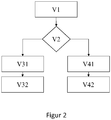
- FIG. 2 shows schematically the sequence of the method according to the invention for operating a hydropower plant.
- the hydropower plant is in the following state: the impeller of the turbine 4 is blown out, so that it can turn in air.
- the double-fed asynchronous machine 5 runs in the so-called phase shifter mode, ie the rotor of the same rotates according to the network frequency (ie within the permissible slip band) and, depending on the excitation state, reactive power can be supplied capacitively or inductively to the network.
- the impeller rotates Turbine 4 with the same rotational speed as the rotor of the double-fed asynchronous machine 5.
- the hydropower plant is prompted to actively provide fast control power.
- the request can be to quickly deliver power to the grid or to quickly take power from the grid.
- the steps of the left branch of the flow diagram are run through, in the second case the steps of the right branch.
- step labeled V31 the double-fed asynchronous machine 5 and the connected turbine 4 are braked via the frequency converter 6.
- the energy stored in the angular momentum of the rotating components is released to the grid.
- the processes taking place in step V31 are very fast and therefore the requested power can be delivered to the network in less than one second.
- step labeled V32 the guide apparatus and possibly further closing elements of the turbine 4 are opened.
- water can get into the previously blown-out area around the impeller of the turbine 4 from the headwater 1.
- the air is expelled towards underwater 2. Due to the water flow, the turbine 4 and the double-fed asynchronous machine 5 are accelerated again to a higher speed, and so power can be continuously supplied to the network.
- step V32 The processes of step V32 are initiated simultaneously with the processes of step V31. However, since the processes in step V32 are much slower than the processes in step V31, they only come into effect much later - usually only after approx. 15-20 seconds. Before that, the power output to the network is determined by the processes of step V31. In step V31, the power output to the network is regulated by the frequency converter 6 and in step V32 by the controller of the turbine 4 with the aid of the control apparatus.
- step labeled V41 the frequency converter 6 draws power from the grid. This performance is achieved with the help of Resistor 8 converted into heat. To do this, the resistor 8 must be cooled. It is advantageous if part of the power that the frequency converter 6 draws from the network is used to accelerate the double-fed asynchronous machine 5 and the impeller of the turbine 4. So less energy in resistor 8 has to be converted into heat.
- the processes taking place in step V41 are very fast and therefore the requested power can be absorbed from the network in less than one second. In principle, the processes described in step V41 can also be used to draw power from the network over a longer period of time. However, energy is constantly converted into heat and thus destroyed, so to speak.
- step V42 the optional pump 9 is started up in order to pump water from the underwater pool 2 into the upper water pool 1.
- power is further absorbed from the network, and the energy thus absorbed by the pump 9 is converted into the position energy of the water and stored for later use in turbine operation.
- the processes from step V42 are initiated simultaneously with the processes from step V41.
- the processes in step V42 run much more slowly than the processes in step V41, they only come into effect much later - usually only after approx. 10 to 15 seconds.
- the power consumption from the network is determined by the processes of step V41.
- step V41 the power consumption from the network is regulated by the frequency converter 6.
- step V42 the power consumption from the network can be regulated in two ways: either the pump 9 has a variable-speed drive, which can thereby regulate the power consumed by the pump 9, or the pump 9 is designed as a pump with a constant speed. In the latter case, the frequency converter 6 takes over the regulation of the power consumed from the network. The nozzle of the turbine 4 is used for speed control. The double-fed asynchronous machine 5 produces a corresponding one electrical power that is fed into the grid. A situation arises which is known as hydraulic short circuit. The net power taken up from the network then results from the pump power minus the power produced by the double-fed asynchronous machine 5.
- the power generated by the double-fed asynchronous machine 5 must be less than the pump power. Since the turbine power and thus the power generated by the double-fed asynchronous machine 5 can be regulated by the frequency converter 6, the net power consumption from the network can thus also be regulated.
- step V2 After processing the request to provide fast control power in step V2, the hydropower plant is returned to the operating state described in step V1. Then the hydropower plant is ready to serve another request.
- the specific design of a hydropower plant according to the invention has shown that it is advantageous if, in step V31, the double-fed asynchronous machine 5 is braked to the minimum permissible speed. It is also advantageous if in step V41 the double-fed asynchronous machine 5 is accelerated to the maximum permissible speed.
- the frequency converter 6 can be designed as a so-called “voltage source inverter” (VSI).
- VSI has the advantage that it enables power factor control and control in the so-called "low voltage ride through”.
- the plant In order that the control power required by the grid code can be optimally made available by the hydropower plant, the plant must be designed so that the capacity to deliver power to the grid corresponds to the capacity of the power consumption from the grid. This requirement must be met both in the short-term area and in the long-term area.
- the invention The structure of the hydropower plant is so flexible that this requirement can be met by designing the components accordingly.
Landscapes
- Engineering & Computer Science (AREA)
- Power Engineering (AREA)
- Chemical & Material Sciences (AREA)
- Combustion & Propulsion (AREA)
- Mechanical Engineering (AREA)
- General Engineering & Computer Science (AREA)
- Control Of Eletrric Generators (AREA)
- Control Of Water Turbines (AREA)
Description
- Die vorliegende Erfindung betrifft eine Wasserkraftanlage, welche zur schnellen Regelung der Netzfrequenz geeignet ist, und ein Verfahren zum Betrieb einer solchen Wasserkraftanlage.
- Die
EP 2 369 169 A2 offenbart eine Wasserkraftanlage, umfassend ein Oberwasserbecken und ein Unterwasserbecken, wobei der Wasserspiegel im Oberwasserbecken über dem Wasserspiegel des Unterwasserbeckens liegt, einen Wasserweg, der das Oberwasserbecken mit dem Unterwasserbecken verbindet, eine Turbine, welche im Wasserweg angeordnet ist, eine elektrische Asynchronmaschine, welche mit der Turbine mechanisch verbunden ist und einen Rotor und einen Stator umfasst, einen Frequenzumrichter, welcher mit der Asynchronmaschine elektrisch verbunden ist, einen Netz-Transformator, welcher mit dem Frequenzumrichter, dem Stator der Asynchronmaschine und dem Stromnetz elektrisch verbunden ist, und einen Widerstand, welcher im Gleichstromzwischenkreis des Frequenzumrichters so angeordnet ist, dass er die Stränge des Gleichstromzwischenkreises miteinander verbinden kann. - Klassische Wasserkraftanlagen können aufgrund der Trägheit der Wassersäule, sowie des maximalen und minimalen zulässigen Wasserdruckes in den Wasserwegen und in der Turbine, die elektrische Leistung nur verhältnismäßig langsam regeln - typischerweise auf einer Zeitskala von 10 - 30 Sekunden. Dies reicht nicht aus um bei den gestiegenen Anforderungen einen Beitrag zur kurzzeitigen Regelung der Netzfrequenz leisten zu können. So fordert beispielsweise der National Grid Code von Großbritannien, dass eine bestimmte elektrische Leistung in Abhängigkeit von der Netzfrequenz in weniger als einer Sekunde ins Netz einzuprägen bzw. zu absorbieren ist, um an der entsprechenden Vergütung zu partizipieren. Es ist Aufgabe der vorliegenden Erfindung eine Wasserkraftanlage anzugeben, die Regelleistung auf einer Zeitskala von unter einer Sekunde bereitstellen kann. Ferner ist es Aufgabe der vorliegenden Erfindung, ein Verfahren zum Betrieb einer solchen Wasserkraftanlage anzugeben.
- Die Erfinder haben erkannt, dass die gestellte Aufgabe durch ein Verfahren zum Betrieb einer Wasserkraftanlage mit den Merkmalen des Anspruchs 1 gelöst werden kann. Vorteilhafte Ausführungsformen ergeben sich aus abhängigen Verfahrensansprüchen.
- Die erfindungsgemäße Lösung wird nachfolgend anhand von Figuren erläutert. Darin ist im Einzelnen folgendes dargestellt:
- Figur 1
- Wasserkraftanlage;
- Figur 2
- Ablaufdiagramm des erfindungsgemäßen Verfahrens zum Betrieb einer Wasserkraftanlage.
-
Figur 1 zeigt den schematischen Aufbau einer Wasserkraftanlage. Die Wasserkraftanlage umfasst ein Oberwasserbecken, welches mit 1 bezeichnet ist, und ein Unterwasserbecken, welches mit 2 bezeichnet ist, wobei der Wasserspiegel im Oberwasserbecken 1 über dem Wasserspiegel des Unterwasserbeckens 2 liegt. Bei den Becken 1 und 2 kann es sich auch um natürliche Gewässer wie beispielsweise Seen oder Flüsse handeln. Die Wasserkraftanlage umfasst ferner einen Wasserweg, welcher mit 3 bezeichnet ist und das Oberwasserbecken 1 mit dem Unterwasserbecken 2 verbindet. Im Wasserweg 3 ist eine Turbine angeordnet, welche mit 4 bezeichnet ist. Dadurch wird der Wasserweg 3 in zwei Teilstücke geteilt. Der oberhalb der Turbine 4 gelegene Teil - die Druckrohrleitung - ist mit 31 bezeichnet, und der unterhalb der Turbine gelegene Teil - das Saugrohr - ist mit 32 bezeichnet. Die Turbine 4 verfügt über ein Turbinenlaufrad, einen Leitapparat und eine Einrichtung zum Ausblasen des Raumes um das Turbinenlaufrades, so dass im ausgeblasenen Zustand das Turbinenlaufrad in Luft rotieren kann, wobei der geschlossene Leitapparat ein Entweichen der Luft in Richtung Oberwasser verhindert. Die Turbine kann optional noch über weitere Schließorgane neben dem Leitapparat verfügen, wie z.B. einen Kugelschieber. Die Turbine 4 ist an eine doppelt gespeiste Asynchronmaschine gekoppelt, welche mit 5 bezeichnet ist. Die doppelt gespeiste Asynchronmaschine 5 umfasst einen Rotor und einen Stator. Der Rotor der doppelt gespeisten Asynchronmaschine 5 ist elektrisch mit einem Frequenzumrichter verbunden, welcher mit 6 bezeichnet ist. Der Frequenzumrichter 6 ist mittels eines Netz-Transformators, welcher mit 7 bezeichnet ist, mit dem Stromnetz verbunden. Der Stator der doppelt gespeisten Asynchronmaschine ist direkt mit dem Transformator 7 verbunden. - Im Gleichstromzwischenkreis des Frequenzumrichters 6 befindet sich ein Widerstand, welcher so geschaltet werden kann, dass er die Stränge des Gleichstromzwischenkreises miteinander verbindet. Der Widerstand ist mit 8 bezeichnet. Ferner umfasst die Wasserkraftanlage optional wenigstens eine Pumpe, welche mit 9 bezeichnet und so angeordnet ist, dass sie Wasser aus dem Unterwasserbecken 2 in das Oberwasserbecken 1 fördern kann. Die Pumpe 9 kann eigene Schließorgane umfassen und besitzt einen eigenständigen Antrieb mit Netzanschluss.
-
Figur 2 zeigt schematisch den Ablauf des erfindungsgemäßen Verfahrens zum Betrieb einer Wasserkraftanlage. Im Schritt, der mit V1 bezeichnet ist, befindet sich die Wasserkraftanlage in folgendem Zustand: Das Laufrad der Turbine 4 ist ausgeblasen, so dass sich dasselbe in Luft drehen kann. Die doppelt gespeiste Asynchronmaschine 5 läuft im sogenannten Phasenschieber-Betrieb, d.h. der Läufer derselben dreht sich gemäß der Netzfrequenz (d.h. innerhalb des zulässigen Schlupfbandes) und je nach Erregungszustand kann Blindleistung kapazitiv oder induktiv ans Netz abgegeben werden. Durch die Kopplung von doppelt gespeister Asynchronmaschine 5 und Turbine 4 dreht sich das Laufrad der Turbine 4 mit derselben Rotationsgeschwindigkeit wie der Rotor der doppelt gespeisten Asynchronmaschine 5. Im Schritt, der mit V2 bezeichnet ist, ergeht an die Wasserkraftanlage die Aufforderung, schnelle Regelleistung aktiv zur Verfügung zu stellen. Die Aufforderung kann dahin gehen, Leistung schnell ans Netz abzugeben oder Leistung schnell vom Netz aufzunehmen. Im ersten Fall werden die Schritte des linken Astes des Ablaufdiagramms durchlaufen, im zweiten Fall die Schritte des rechten Astes. - Leistungsabgabe an das Netz: Im mit V31 bezeichneten Schritt wird über den Frequenzumrichter 6 die doppelt gespeiste Asynchronmaschine 5 und die verbundene Turbine 4 abgebremst. Dabei wird die im Drehimpuls der rotierenden Komponenten gespeicherte Energie an das Netz abgegeben. Die in Schritt V31 ablaufenden Vorgänge sind sehr schnell und daher kann unterhalb von einer Sekunde die angeforderte Leistung ans Netz abgeben werden. Im mit V32 bezeichneten Schritt wird der Leitapparat und ggf. weitere Schließorgane der Turbine 4 geöffnet. Dadurch kann Wasser in den zuvor ausgeblasenen Bereich um das Laufrad der Turbine 4 vom Oberwasser 1 her gelangen. Die Luft wird in Richtung Unterwasser 2 ausgetrieben. Durch den Wasserfluss wird die Turbine 4 und die doppelt gespeiste Asynchronmaschine 5 wieder auf eine höhere Drehzahl beschleunigt und so kann dauerhaft Leistung ans Netz abgegeben werden. Die Vorgänge von Schritt V32 werden simultan mit den Vorgängen von Schritt V31 initiiert. Da die Vorgänge von Schritt V32 jedoch viel langsamer ablaufen als die Vorgänge von Schritt V31, kommen diese erst viel später zum Tragen - in der Regel erst nach ca. 15-20 Sekunden. Davor wird die Leistungsabgabe an das Netz durch die Vorgänge von Schritt V31 bestimmt. Im Schritt V31 wird die Leistungsabgabe an das Netz durch den Frequenzumrichter 6 geregelt und im Schritt V32 durch den Regler der Turbine 4 mit Hilfe des Leitapparats.
- Leistungsaufnahme vom Netz: Im mit V41 bezeichneten Schritt zieht der Frequenzumrichter 6 Leistung aus dem Netz. Diese Leistung wird mit Hilfe des Widerstandes 8 in Wärme umgewandelt. Dazu muss der Widerstand 8 gekühlt werden. Es ist von Vorteil, wenn ein Teil der Leistung, die der Frequenzumrichter 6 aus dem Netz zieht, dazu verwendet wird, um die doppelt gespeiste Asynchronmaschine 5 und das Laufrad der Turbine 4 zu beschleunigen. So muss weniger Energie im Widerstand 8 in Wärme umgewandelt werden. Die in Schritt V41 ablaufenden Vorgänge sind sehr schnell und daher kann unterhalb von einer Sekunde die angeforderte Leistung aus dem Netz absorbiert werden. Im Prinzip kann mit den in Schritt V41 beschriebenen Vorgängen allein auch über einen längeren Zeitraum Leistung aus dem Netz aufgenommen werden. Allerdings wird dabei ständig Energie in Wärme umgewandelt und somit sozusagen vernichtet. Es ist daher von Vorteil, wenn die Energie in V41 nur kurzzeitig in Wärme umgewandelt wird. Dazu wird im optionalen Schritt, welcher mit V42 bezeichnet ist, die optionale Pumpe 9 hochgefahren, um Wasser aus dem Unterwasserbecken 2 ins Oberwasserbecken 1 zu pumpen. Dadurch wird weiter Leistung aus dem Netz absorbiert, und die so von der Pumpe 9 aufgenommene Energie wird in Lageenergie des Wassers umgewandelt und zur späteren Verwendung im Turbinenbetrieb gespeichert. Die Vorgänge von Schritt V42 werden dabei simultan mit den Vorgängen von Schritt V41 initiiert. Da die Vorgänge von Schritt V42 jedoch viel langsamer ablaufen als die Vorgänge von Schritt V41, kommen diese erst viel später zum Tragen - in der Regel erst nach ca. 10 bis 15 Sekunden. Davor wird die Leistungsaufnahme aus dem Netz durch die Vorgänge von Schritt V41 bestimmt. Im Schritt V41 wird die Leistungsaufnahme aus dem Netz durch den Frequenzumrichter 6 geregelt. Im Schritt V42 kann die Leistungsaufnahme aus dem Netz auf zweierlei Weise geregelt werden: Entweder verfügt die Pumpe 9 über einen drehzahlvariablen Antrieb, der dadurch die von der Pumpe 9 aufgenommene Leistung regeln kann, oder die Pumpe 9 ist als Pumpe mit konstanter Drehzahl ausgebildet. Im letzteren Fall übernimmt der Frequenzumrichter 6 die Regelung der aus dem Netz aufgenommenen Leistung. Der Leitapparat der Turbine 4 wird zur Drehzahlregelung eingesetzt. Dabei produziert die doppelt gespeiste Asynchronmaschine 5 eine entsprechende elektrische Leistung, die ins Netz eingespeist wird. Es ergibt sich eine Situation, die unter dem Namen hydraulischer Kurzschluss bekannt ist. Die aus dem Netz aufgenommen Netto-Leistung ergibt sich dann aus der Pumpenleistung minus der von der doppelt gespeisten Asynchronmaschine 5 produzierten Leistung. Es ist klar, dass die von der doppelt gespeisten Asynchronmaschine 5 erzeugte Leistung dabei geringer sein muss als die Pumpenleistung. Da die Turbinenleistung und damit die von der doppelt gespeisten Asynchronmaschine 5 erzeugte Leistung durch den Frequenzumrichter 6 geregelt werden kann, kann somit auch die Netto-Leistungsaufnahme aus dem Netz geregelt werden.
- Nach Abarbeitung der im Schritt V2 ergangenen Aufforderung zur Bereitstellung von schneller Regelleistung, wird die Wasserkraftanlage wieder in den unter Schritt V1 beschriebenen Betriebszustand versetzt. Dann ist die Wasserkraftanlage wieder bereit eine weitere Aufforderung zu bedienen.
- Die konkrete Auslegung einer erfindungsgemäßen Wasserkraftanlage hat ergeben, dass es vorteilhaft ist, wenn im Schritt V31 die doppelt gespeiste Asynchronmaschine 5 auf die minimal zulässige Drehzahl abgebremst wird. Ebenso ist es vorteilhaft, wenn im Schritt V41 die doppelt gespeiste Asynchronmaschine 5 auf die maximal zulässige Drehzahl beschleunigt wird. Der Frequenzumrichter 6 kann als sogenannter "Voltage Source Inverter" (VSI) ausgebildet sein. Der VSI hat den Vorteil, dass er eine Leistungsfaktor-Regelung und eine Regelung im sogenannten "Low Voltage Ride Through" ermöglicht.
- Damit die vom Grid Code geforderte Regelleistung durch die Wasserkraftanlage optimal zur Verfügung gestellt werden kann, muss die Anlage so ausgelegt sein, dass die Kapazität zur Leistungsabgabe an das Netz der Kapazität der Leistungsaufnahme aus dem Netz entspricht. Diese Anforderung muss sowohl im Kurzzeitbereich als auch im Langzeitbereich erfüllt sein. Die erfindungsgemäße Wasserkraftanlage ist durch ihren Aufbau so flexibel, dass diese Anforderung durch eine entsprechende Auslegung der Komponenten erfüllt werden kann.
Claims (8)
- Verfahren zum Betrieb einer Wasserkraftanlage mit einem Oberwasserbecken (1), einem Unterwasserbecken (2), wobei der Wasserspiegel im Oberwasserbecken (1) über dem Wasserspiegel des Unterwasserbeckens (2) liegt, einem Wasserweg (3), der das Oberwasserbecken (1) mit dem Unterwasserbecken (2) verbindet, einer Turbine (4), welche im Wasserweg (3) angeordnet ist und ein Laufrad umfasst, einer elektrische Asynchronmaschine (5), welche mit der Turbine (4) mechanisch verbunden ist und einen Rotor und einen Stator umfasst, einem Frequenzumrichter (6), welcher mit der Asynchronmaschine elektrisch verbunden ist, einem Netz-Transformator (7) welcher mit dem Frequenzumrichter (6), dem Stator der doppelt gespeisten Asynchronmaschine (5) und dem Stromnetz elektrisch verbunden ist, und einem Widerstand (8) welcher im Gleichstromzwischenkreis des Frequenzumrichters (6) so angeordnet ist, dass er die Stränge des Gleichstromzwischenkreises miteinander verbinden kann, dadurch gekennzeichnet, dass die Turbine einen Leitapparat und eine Einrichtung zum Ausblasen des Laufradraumes umfasst, die Asynchronmaschine doppelt gespeist ausgeführt ist, der Frequenzumrichter mit dem Rotor der Asynchronmaschine verbunden ist, und die Wasserkraftanlage eine Einrichtung zur Kühlung des Widerstandes (8) umfasst,
umfassend die folgenden Schritte:V1: Das Laufrad der Turbine (4) ist ausgeblasen und die doppelt gespeiste Asynchronmaschine (5) läuft im Phasenschieber-Betrieb;V2: Empfang einer Aufforderung an die Wasserkraftanlage, schnelle Regelleistung zur Verfügung zu stellen;Bei Aufforderung zur Leistungsabgabe:V31: Bremsen der doppelt gespeisten Asynchronmaschine (5) durch den Frequenzumrichter (6);V32: Öffnen der Leitschaufeln der Turbine (4) und Start des geregelten Turbinenbetriebs;Bei Aufforderung zur Leistungsaufnahme:
V41: Aufnahme von Energie aus dem Netz durch den Frequenzumrichter (6) und Umwandlung der Energie in Wärme durch den Widerstand (8); - Verfahren nach Anspruch 6 1, wobei die Wasserkraftanlage eine Pumpe (9) umfasst, welche so angeordnet ist, dass sie Wasser aus dem Unterwasserbecken (2) in das Oberwasserbecken (1) fördern kann, wobei die Pumpe (9) einen eigenständigen Antrieb umfasst, und wobei das Verfahren bei Aufforderung zur Leistungsaufnahme den folgenden zusätzlichen Schritt umfasst:
V42: Anfahren der Pumpe (9) und Start des geregelten Pumpenbetriebs; - Verfahren nach einem der Ansprüche 1 bis 2, wobei die doppelt gespeiste Asynchronmaschine (5) im Schritt V41 durch den Frequenzumrichter (6) beschleunigt wird.
- Verfahren nach einem der Ansprüche 1 bis 3, wobei die doppelt gespeiste Asynchronmaschine (5) im Schritt V31 auf die minimal zulässige Drehzahl abgebremst wird.
- Verfahren nach einem der Ansprüche 1, 2 oder 4, wobei die doppelt gespeiste Asynchronmaschine (5) im Schritt V41 auf die maximal zulässige Drehzahl beschleunigt wird.
- Verfahren nach einem der Ansprüche 1 bis 5 in Verbindung mit Anspruch 2, wobei die Pumpe (9) einen drehzahlvariablen Antrieb umfasst, und wobei der geregelte Pumpenbetrieb in Schritt V42 durch den drehzahlvariablen Pumpenantrieb geregelt wird.
- Verfahren nach einem der Ansprüche 1 bis 5 in Verbindung mit Anspruch 2, wobei die Pumpe (9) einen Antrieb mit konstanter Drehzahl umfasst, und wobei im Schritt V42 der Leitapparat der Turbine (4) geöffnet wird und der geregelte Pumpenbetrieb in Schritt V42 durch den Frequenzumrichter (6) und den Leitapparat der Turbine (4) geregelt wird, wobei sich die Turbine (4) und die Pumpe (9) im hydraulischen Kurzschluss befinden.
- Verfahren nach einem der Ansprüche 1 bis 7, wobei der Frequenzumrichter (6) als sogenannter "Voltage Source Inverter" ausgebildet ist.
Applications Claiming Priority (3)
| Application Number | Priority Date | Filing Date | Title |
|---|---|---|---|
| DE102017107992 | 2017-04-13 | ||
| DE102017118194.6A DE102017118194A1 (de) | 2017-08-10 | 2017-08-10 | Wasserkraftanlage zur Regelung der Netzfrequenz und Verfahren zum Betrieb |
| PCT/EP2018/058121 WO2018188965A1 (de) | 2017-04-13 | 2018-03-29 | Wasserkraftanlage zur regelung der netzfrequenz und verfahren zum betrieb |
Publications (2)
| Publication Number | Publication Date |
|---|---|
| EP3610151A1 EP3610151A1 (de) | 2020-02-19 |
| EP3610151B1 true EP3610151B1 (de) | 2020-07-01 |
Family
ID=61868515
Family Applications (1)
| Application Number | Title | Priority Date | Filing Date |
|---|---|---|---|
| EP18715013.1A Active EP3610151B1 (de) | 2017-04-13 | 2018-03-29 | Verfahren zum betrieb einer wasserkraftanlage zur regelung der netzfrequenz |
Country Status (4)
| Country | Link |
|---|---|
| US (1) | US20200158076A1 (de) |
| EP (1) | EP3610151B1 (de) |
| CN (1) | CN110621872B (de) |
| WO (1) | WO2018188965A1 (de) |
Families Citing this family (1)
| Publication number | Priority date | Publication date | Assignee | Title |
|---|---|---|---|---|
| CN110663153B (zh) * | 2017-04-13 | 2023-02-10 | 福伊特专利有限公司 | 用于调节电网频率的水力发电设备和用于运行的方法 |
Family Cites Families (18)
| Publication number | Priority date | Publication date | Assignee | Title |
|---|---|---|---|---|
| DE2421409A1 (de) * | 1974-05-03 | 1975-11-13 | Michael Blumenthal | Verfahren zur speisung eines netzes fester frequenz durch eine mit variabler drehzahl betriebene synchronmaschine |
| US3939356A (en) * | 1974-07-24 | 1976-02-17 | General Public Utilities Corporation | Hydro-air storage electrical generation system |
| US4426846A (en) * | 1978-04-24 | 1984-01-24 | Wayne Bailey | Hydraulic power plant |
| US5742515A (en) * | 1995-04-21 | 1998-04-21 | General Electric Co. | Asynchronous conversion method and apparatus for use with variable speed turbine hydroelectric generation |
| US6861766B2 (en) * | 2001-12-03 | 2005-03-01 | Peter Rembert | Hydro-electric generating system |
| CN101413476B (zh) * | 2008-11-20 | 2011-05-18 | 邓庆时 | 海底抽排尾水式水力发电系统 |
| DE102009011784B3 (de) * | 2009-03-09 | 2010-07-22 | Voith Patent Gmbh | Verfahren und Vorrichtung zum Bremsen eines Unterwasserkraftwerks |
| GB0910867D0 (en) * | 2009-06-24 | 2009-08-05 | Design Tech & Innovation Ltd | Water power generators |
| EP2270331B1 (de) * | 2009-06-30 | 2020-03-04 | Vestas Wind Systems A/S | Windkraftanlage mit Steuerungsvorrichtung zur Leistungsregelung während Netzstörungen |
| DE202010003347U1 (de) * | 2010-03-09 | 2010-06-24 | Ritz-Atro Gmbh | Wasserkraftanlage |
| CN103081273B (zh) * | 2010-06-30 | 2016-05-11 | 维斯塔斯风力系统有限公司 | 风力涡轮机 |
| JP5640541B2 (ja) * | 2010-08-10 | 2014-12-17 | 三菱電機株式会社 | 系統連系インバータ装置 |
| DE102011015336A1 (de) * | 2011-03-28 | 2012-01-12 | Voith Patent Gmbh | Vorrichtung und Verfahren zur Diagnose von Luftleckagen hydraulische Maschinen |
| US9041234B2 (en) * | 2012-03-26 | 2015-05-26 | Rockwell Automation Technologies, Inc. | Double fed induction generator (DFIG) converter and method for improved grid fault ridethrough |
| JP6305756B2 (ja) * | 2013-12-24 | 2018-04-04 | 日立三菱水力株式会社 | 揚水発電装置 |
| CN203942288U (zh) * | 2014-06-06 | 2014-11-12 | 华南理工大学 | 一种双馈发电机组交、直流并网系统 |
| CN110663153B (zh) * | 2017-04-13 | 2023-02-10 | 福伊特专利有限公司 | 用于调节电网频率的水力发电设备和用于运行的方法 |
| AU2018293589C1 (en) * | 2017-06-29 | 2023-06-29 | Henry K. Obermeyer | Improved reversible pump-turbine installation |
-
2018
- 2018-03-29 CN CN201880031644.3A patent/CN110621872B/zh active Active
- 2018-03-29 US US16/604,896 patent/US20200158076A1/en not_active Abandoned
- 2018-03-29 WO PCT/EP2018/058121 patent/WO2018188965A1/de not_active Ceased
- 2018-03-29 EP EP18715013.1A patent/EP3610151B1/de active Active
Non-Patent Citations (1)
| Title |
|---|
| None * |
Also Published As
| Publication number | Publication date |
|---|---|
| EP3610151A1 (de) | 2020-02-19 |
| US20200158076A1 (en) | 2020-05-21 |
| WO2018188965A1 (de) | 2018-10-18 |
| CN110621872B (zh) | 2020-12-01 |
| CN110621872A (zh) | 2019-12-27 |
Similar Documents
| Publication | Publication Date | Title |
|---|---|---|
| DE10314757B3 (de) | Antriebsstrang zum Übertragen einer variablen Leistung | |
| DE102008013864A1 (de) | Verfahren und Vorrichtung zum Drehen einer Komponente einer Windenergieanlage | |
| EP2406877B1 (de) | Verfahren und vorrichtung zum bremsen eines unterwasserkraftwerks | |
| EP1538739A2 (de) | Antriebsstrang für eine Strömungskraftmaschine | |
| WO2005017350A1 (de) | Windenergieanlage mit einer rotorblattverstelleinrichtung | |
| DE102013004580A1 (de) | Verfahren zum Arretieren einer Windturbine und Windturbine zur Durchführung des Verfahrens | |
| AT507643A2 (de) | Verbesserungen für und bezogen auf die erzeugung elektrischer energie aus einem fluidstrom | |
| DE3308564A1 (de) | Windturbinenanlage | |
| EP3610547B1 (de) | Verfahren zum betrieb einer wasserkraftanlage zur regelung der netzfrequenz | |
| DE102011107286A1 (de) | Strömungskraftwerk und Verfahren für dessen Betrieb | |
| WO2019185267A1 (de) | Verfahren zum betrieb eines pumpspeicherkraftwerks | |
| EP3610151B1 (de) | Verfahren zum betrieb einer wasserkraftanlage zur regelung der netzfrequenz | |
| DE112015004161T5 (de) | Verfahren zum betätigen eines elektrischen meeresströmungsleistungsgenerators und betätigungssteuervorrichtung | |
| AT6889U1 (de) | Verfahren und vorrichtung zur leistungsregelung in einem speicherkraftwerk | |
| DE102004005191A1 (de) | Verfahren und Vorrichtung zum Anfahren der Pumpturbine eines Pumpspeicherkraftwerkes | |
| EP1998040A2 (de) | Antriebsstrang für eine tauchende Energieerzeugungsanlage | |
| DE2935480C3 (de) | Verfahren zum Betrieb einer Pumpenturbine zwischen Teillast- und Rückwärtspumpenbetrieb. | |
| DE102017118194A1 (de) | Wasserkraftanlage zur Regelung der Netzfrequenz und Verfahren zum Betrieb | |
| DE102012205159A1 (de) | Turbinensystem mit drei an einem zentralen Getriebe angekoppelten Turbinen, Turbinenanlage und Verfahren zum Betreiben einer Arbeitsmaschine | |
| EP3759338B1 (de) | Kombiniertes kraftwerk und verfahren zum betrieb | |
| EP3707370B1 (de) | Strömungsmaschine zum bereitstellen von elektrischer energie | |
| EP1426616B1 (de) | Netzkopplung einer Windkraftanlage | |
| DE3702701A1 (de) | Wasserkraftanlage | |
| DE102022102237B3 (de) | Pelton Turbine und Betriebsverfahren | |
| DE102011121544A1 (de) | Windenergieanlage |
Legal Events
| Date | Code | Title | Description |
|---|---|---|---|
| STAA | Information on the status of an ep patent application or granted ep patent |
Free format text: STATUS: UNKNOWN |
|
| STAA | Information on the status of an ep patent application or granted ep patent |
Free format text: STATUS: THE INTERNATIONAL PUBLICATION HAS BEEN MADE |
|
| PUAI | Public reference made under article 153(3) epc to a published international application that has entered the european phase |
Free format text: ORIGINAL CODE: 0009012 |
|
| STAA | Information on the status of an ep patent application or granted ep patent |
Free format text: STATUS: REQUEST FOR EXAMINATION WAS MADE |
|
| 17P | Request for examination filed |
Effective date: 20191113 |
|
| AK | Designated contracting states |
Kind code of ref document: A1 Designated state(s): AL AT BE BG CH CY CZ DE DK EE ES FI FR GB GR HR HU IE IS IT LI LT LU LV MC MK MT NL NO PL PT RO RS SE SI SK SM TR |
|
| AX | Request for extension of the european patent |
Extension state: BA ME |
|
| REG | Reference to a national code |
Ref country code: DE Ref legal event code: R079 Ref document number: 502018001802 Country of ref document: DE Free format text: PREVIOUS MAIN CLASS: F03B0015000000 Ipc: F03B0013060000 |
|
| RIC1 | Information provided on ipc code assigned before grant |
Ipc: H02J 3/28 20060101ALI20200221BHEP Ipc: H02J 3/38 20060101ALI20200221BHEP Ipc: H02J 3/48 20060101ALI20200221BHEP Ipc: F03B 13/06 20060101AFI20200221BHEP |
|
| GRAP | Despatch of communication of intention to grant a patent |
Free format text: ORIGINAL CODE: EPIDOSNIGR1 |
|
| STAA | Information on the status of an ep patent application or granted ep patent |
Free format text: STATUS: GRANT OF PATENT IS INTENDED |
|
| GRAS | Grant fee paid |
Free format text: ORIGINAL CODE: EPIDOSNIGR3 |
|
| INTG | Intention to grant announced |
Effective date: 20200429 |
|
| GRAA | (expected) grant |
Free format text: ORIGINAL CODE: 0009210 |
|
| STAA | Information on the status of an ep patent application or granted ep patent |
Free format text: STATUS: THE PATENT HAS BEEN GRANTED |
|
| AK | Designated contracting states |
Kind code of ref document: B1 Designated state(s): AL AT BE BG CH CY CZ DE DK EE ES FI FR GB GR HR HU IE IS IT LI LT LU LV MC MK MT NL NO PL PT RO RS SE SI SK SM TR |
|
| DAV | Request for validation of the european patent (deleted) | ||
| DAX | Request for extension of the european patent (deleted) | ||
| REG | Reference to a national code |
Ref country code: CH Ref legal event code: EP Ref country code: AT Ref legal event code: REF Ref document number: 1286410 Country of ref document: AT Kind code of ref document: T Effective date: 20200715 |
|
| REG | Reference to a national code |
Ref country code: IE Ref legal event code: FG4D Free format text: LANGUAGE OF EP DOCUMENT: GERMAN |
|
| REG | Reference to a national code |
Ref country code: DE Ref legal event code: R096 Ref document number: 502018001802 Country of ref document: DE |
|
| REG | Reference to a national code |
Ref country code: LT Ref legal event code: MG4D |
|
| PG25 | Lapsed in a contracting state [announced via postgrant information from national office to epo] |
Ref country code: BG Free format text: LAPSE BECAUSE OF FAILURE TO SUBMIT A TRANSLATION OF THE DESCRIPTION OR TO PAY THE FEE WITHIN THE PRESCRIBED TIME-LIMIT Effective date: 20201001 |
|
| REG | Reference to a national code |
Ref country code: NL Ref legal event code: MP Effective date: 20200701 |
|
| PG25 | Lapsed in a contracting state [announced via postgrant information from national office to epo] |
Ref country code: SE Free format text: LAPSE BECAUSE OF FAILURE TO SUBMIT A TRANSLATION OF THE DESCRIPTION OR TO PAY THE FEE WITHIN THE PRESCRIBED TIME-LIMIT Effective date: 20200701 Ref country code: LT Free format text: LAPSE BECAUSE OF FAILURE TO SUBMIT A TRANSLATION OF THE DESCRIPTION OR TO PAY THE FEE WITHIN THE PRESCRIBED TIME-LIMIT Effective date: 20200701 Ref country code: PT Free format text: LAPSE BECAUSE OF FAILURE TO SUBMIT A TRANSLATION OF THE DESCRIPTION OR TO PAY THE FEE WITHIN THE PRESCRIBED TIME-LIMIT Effective date: 20201102 Ref country code: ES Free format text: LAPSE BECAUSE OF FAILURE TO SUBMIT A TRANSLATION OF THE DESCRIPTION OR TO PAY THE FEE WITHIN THE PRESCRIBED TIME-LIMIT Effective date: 20200701 Ref country code: HR Free format text: LAPSE BECAUSE OF FAILURE TO SUBMIT A TRANSLATION OF THE DESCRIPTION OR TO PAY THE FEE WITHIN THE PRESCRIBED TIME-LIMIT Effective date: 20200701 Ref country code: CZ Free format text: LAPSE BECAUSE OF FAILURE TO SUBMIT A TRANSLATION OF THE DESCRIPTION OR TO PAY THE FEE WITHIN THE PRESCRIBED TIME-LIMIT Effective date: 20200701 Ref country code: FI Free format text: LAPSE BECAUSE OF FAILURE TO SUBMIT A TRANSLATION OF THE DESCRIPTION OR TO PAY THE FEE WITHIN THE PRESCRIBED TIME-LIMIT Effective date: 20200701 Ref country code: GR Free format text: LAPSE BECAUSE OF FAILURE TO SUBMIT A TRANSLATION OF THE DESCRIPTION OR TO PAY THE FEE WITHIN THE PRESCRIBED TIME-LIMIT Effective date: 20201002 Ref country code: NO Free format text: LAPSE BECAUSE OF FAILURE TO SUBMIT A TRANSLATION OF THE DESCRIPTION OR TO PAY THE FEE WITHIN THE PRESCRIBED TIME-LIMIT Effective date: 20201001 |
|
| PG25 | Lapsed in a contracting state [announced via postgrant information from national office to epo] |
Ref country code: LV Free format text: LAPSE BECAUSE OF FAILURE TO SUBMIT A TRANSLATION OF THE DESCRIPTION OR TO PAY THE FEE WITHIN THE PRESCRIBED TIME-LIMIT Effective date: 20200701 Ref country code: RS Free format text: LAPSE BECAUSE OF FAILURE TO SUBMIT A TRANSLATION OF THE DESCRIPTION OR TO PAY THE FEE WITHIN THE PRESCRIBED TIME-LIMIT Effective date: 20200701 Ref country code: PL Free format text: LAPSE BECAUSE OF FAILURE TO SUBMIT A TRANSLATION OF THE DESCRIPTION OR TO PAY THE FEE WITHIN THE PRESCRIBED TIME-LIMIT Effective date: 20200701 Ref country code: IS Free format text: LAPSE BECAUSE OF FAILURE TO SUBMIT A TRANSLATION OF THE DESCRIPTION OR TO PAY THE FEE WITHIN THE PRESCRIBED TIME-LIMIT Effective date: 20201101 |
|
| PG25 | Lapsed in a contracting state [announced via postgrant information from national office to epo] |
Ref country code: NL Free format text: LAPSE BECAUSE OF FAILURE TO SUBMIT A TRANSLATION OF THE DESCRIPTION OR TO PAY THE FEE WITHIN THE PRESCRIBED TIME-LIMIT Effective date: 20200701 |
|
| REG | Reference to a national code |
Ref country code: DE Ref legal event code: R097 Ref document number: 502018001802 Country of ref document: DE |
|
| PG25 | Lapsed in a contracting state [announced via postgrant information from national office to epo] |
Ref country code: IT Free format text: LAPSE BECAUSE OF FAILURE TO SUBMIT A TRANSLATION OF THE DESCRIPTION OR TO PAY THE FEE WITHIN THE PRESCRIBED TIME-LIMIT Effective date: 20200701 Ref country code: DK Free format text: LAPSE BECAUSE OF FAILURE TO SUBMIT A TRANSLATION OF THE DESCRIPTION OR TO PAY THE FEE WITHIN THE PRESCRIBED TIME-LIMIT Effective date: 20200701 Ref country code: RO Free format text: LAPSE BECAUSE OF FAILURE TO SUBMIT A TRANSLATION OF THE DESCRIPTION OR TO PAY THE FEE WITHIN THE PRESCRIBED TIME-LIMIT Effective date: 20200701 Ref country code: EE Free format text: LAPSE BECAUSE OF FAILURE TO SUBMIT A TRANSLATION OF THE DESCRIPTION OR TO PAY THE FEE WITHIN THE PRESCRIBED TIME-LIMIT Effective date: 20200701 Ref country code: SM Free format text: LAPSE BECAUSE OF FAILURE TO SUBMIT A TRANSLATION OF THE DESCRIPTION OR TO PAY THE FEE WITHIN THE PRESCRIBED TIME-LIMIT Effective date: 20200701 |
|
| PLBE | No opposition filed within time limit |
Free format text: ORIGINAL CODE: 0009261 |
|
| STAA | Information on the status of an ep patent application or granted ep patent |
Free format text: STATUS: NO OPPOSITION FILED WITHIN TIME LIMIT |
|
| PG25 | Lapsed in a contracting state [announced via postgrant information from national office to epo] |
Ref country code: AL Free format text: LAPSE BECAUSE OF FAILURE TO SUBMIT A TRANSLATION OF THE DESCRIPTION OR TO PAY THE FEE WITHIN THE PRESCRIBED TIME-LIMIT Effective date: 20200701 |
|
| 26N | No opposition filed |
Effective date: 20210406 |
|
| PG25 | Lapsed in a contracting state [announced via postgrant information from national office to epo] |
Ref country code: SK Free format text: LAPSE BECAUSE OF FAILURE TO SUBMIT A TRANSLATION OF THE DESCRIPTION OR TO PAY THE FEE WITHIN THE PRESCRIBED TIME-LIMIT Effective date: 20200701 |
|
| PG25 | Lapsed in a contracting state [announced via postgrant information from national office to epo] |
Ref country code: MC Free format text: LAPSE BECAUSE OF FAILURE TO SUBMIT A TRANSLATION OF THE DESCRIPTION OR TO PAY THE FEE WITHIN THE PRESCRIBED TIME-LIMIT Effective date: 20200701 |
|
| REG | Reference to a national code |
Ref country code: BE Ref legal event code: MM Effective date: 20210331 |
|
| PG25 | Lapsed in a contracting state [announced via postgrant information from national office to epo] |
Ref country code: IE Free format text: LAPSE BECAUSE OF NON-PAYMENT OF DUE FEES Effective date: 20210329 Ref country code: LU Free format text: LAPSE BECAUSE OF NON-PAYMENT OF DUE FEES Effective date: 20210329 |
|
| PG25 | Lapsed in a contracting state [announced via postgrant information from national office to epo] |
Ref country code: BE Free format text: LAPSE BECAUSE OF NON-PAYMENT OF DUE FEES Effective date: 20210331 |
|
| GBPC | Gb: european patent ceased through non-payment of renewal fee |
Effective date: 20220329 |
|
| PG25 | Lapsed in a contracting state [announced via postgrant information from national office to epo] |
Ref country code: GB Free format text: LAPSE BECAUSE OF NON-PAYMENT OF DUE FEES Effective date: 20220329 |
|
| PG25 | Lapsed in a contracting state [announced via postgrant information from national office to epo] |
Ref country code: CY Free format text: LAPSE BECAUSE OF FAILURE TO SUBMIT A TRANSLATION OF THE DESCRIPTION OR TO PAY THE FEE WITHIN THE PRESCRIBED TIME-LIMIT Effective date: 20200701 |
|
| PG25 | Lapsed in a contracting state [announced via postgrant information from national office to epo] |
Ref country code: HU Free format text: LAPSE BECAUSE OF FAILURE TO SUBMIT A TRANSLATION OF THE DESCRIPTION OR TO PAY THE FEE WITHIN THE PRESCRIBED TIME-LIMIT; INVALID AB INITIO Effective date: 20180329 |
|
| PG25 | Lapsed in a contracting state [announced via postgrant information from national office to epo] |
Ref country code: SI Free format text: LAPSE BECAUSE OF FAILURE TO SUBMIT A TRANSLATION OF THE DESCRIPTION OR TO PAY THE FEE WITHIN THE PRESCRIBED TIME-LIMIT Effective date: 20200701 |
|
| PG25 | Lapsed in a contracting state [announced via postgrant information from national office to epo] |
Ref country code: MK Free format text: LAPSE BECAUSE OF FAILURE TO SUBMIT A TRANSLATION OF THE DESCRIPTION OR TO PAY THE FEE WITHIN THE PRESCRIBED TIME-LIMIT Effective date: 20200701 |
|
| PG25 | Lapsed in a contracting state [announced via postgrant information from national office to epo] |
Ref country code: TR Free format text: LAPSE BECAUSE OF FAILURE TO SUBMIT A TRANSLATION OF THE DESCRIPTION OR TO PAY THE FEE WITHIN THE PRESCRIBED TIME-LIMIT Effective date: 20200701 |
|
| PG25 | Lapsed in a contracting state [announced via postgrant information from national office to epo] |
Ref country code: MT Free format text: LAPSE BECAUSE OF FAILURE TO SUBMIT A TRANSLATION OF THE DESCRIPTION OR TO PAY THE FEE WITHIN THE PRESCRIBED TIME-LIMIT Effective date: 20200701 |
|
| PGFP | Annual fee paid to national office [announced via postgrant information from national office to epo] |
Ref country code: CH Payment date: 20250401 Year of fee payment: 8 |
|
| REG | Reference to a national code |
Ref country code: CH Ref legal event code: U11 Free format text: ST27 STATUS EVENT CODE: U-0-0-U10-U11 (AS PROVIDED BY THE NATIONAL OFFICE) Effective date: 20260401 |
|
| PGFP | Annual fee paid to national office [announced via postgrant information from national office to epo] |
Ref country code: DE Payment date: 20260319 Year of fee payment: 9 |
|
| PGFP | Annual fee paid to national office [announced via postgrant information from national office to epo] |
Ref country code: AT Payment date: 20260320 Year of fee payment: 9 |
|
| PGFP | Annual fee paid to national office [announced via postgrant information from national office to epo] |
Ref country code: FR Payment date: 20260320 Year of fee payment: 9 |