EP3609796B1 - Schaukasten und teilesatz dafür - Google Patents
Schaukasten und teilesatz dafür Download PDFInfo
- Publication number
- EP3609796B1 EP3609796B1 EP18724233.4A EP18724233A EP3609796B1 EP 3609796 B1 EP3609796 B1 EP 3609796B1 EP 18724233 A EP18724233 A EP 18724233A EP 3609796 B1 EP3609796 B1 EP 3609796B1
- Authority
- EP
- European Patent Office
- Prior art keywords
- panel
- edge
- edges
- front door
- pair
- Prior art date
- Legal status (The legal status is an assumption and is not a legal conclusion. Google has not performed a legal analysis and makes no representation as to the accuracy of the status listed.)
- Active
Links
Images


Classifications
-
- B—PERFORMING OPERATIONS; TRANSPORTING
- B65—CONVEYING; PACKING; STORING; HANDLING THIN OR FILAMENTARY MATERIAL
- B65D—CONTAINERS FOR STORAGE OR TRANSPORT OF ARTICLES OR MATERIALS, e.g. BAGS, BARRELS, BOTTLES, BOXES, CANS, CARTONS, CRATES, DRUMS, JARS, TANKS, HOPPERS, FORWARDING CONTAINERS; ACCESSORIES, CLOSURES, OR FITTINGS THEREFOR; PACKAGING ELEMENTS; PACKAGES
- B65D85/00—Containers, packaging elements or packages, specially adapted for particular articles or materials
- B65D85/18—Containers, packaging elements or packages, specially adapted for particular articles or materials for wearing apparel, headwear or footwear
- B65D85/187—Containers, packaging elements or packages, specially adapted for particular articles or materials for wearing apparel, headwear or footwear for footwear
-
- B—PERFORMING OPERATIONS; TRANSPORTING
- B65—CONVEYING; PACKING; STORING; HANDLING THIN OR FILAMENTARY MATERIAL
- B65D—CONTAINERS FOR STORAGE OR TRANSPORT OF ARTICLES OR MATERIALS, e.g. BAGS, BARRELS, BOTTLES, BOXES, CANS, CARTONS, CRATES, DRUMS, JARS, TANKS, HOPPERS, FORWARDING CONTAINERS; ACCESSORIES, CLOSURES, OR FITTINGS THEREFOR; PACKAGING ELEMENTS; PACKAGES
- B65D11/00—Containers having bodies formed by interconnecting or uniting two or more rigid, or substantially rigid, components made wholly or mainly of plastics material
- B65D11/18—Containers having bodies formed by interconnecting or uniting two or more rigid, or substantially rigid, components made wholly or mainly of plastics material collapsible, i.e. with walls hinged together or detachably connected
- B65D11/1866—Containers having bodies formed by interconnecting or uniting two or more rigid, or substantially rigid, components made wholly or mainly of plastics material collapsible, i.e. with walls hinged together or detachably connected with detachable components
- B65D11/1873—Containers having bodies formed by interconnecting or uniting two or more rigid, or substantially rigid, components made wholly or mainly of plastics material collapsible, i.e. with walls hinged together or detachably connected with detachable components all walls are detached from each other to collapse the container
-
- B—PERFORMING OPERATIONS; TRANSPORTING
- B65—CONVEYING; PACKING; STORING; HANDLING THIN OR FILAMENTARY MATERIAL
- B65D—CONTAINERS FOR STORAGE OR TRANSPORT OF ARTICLES OR MATERIALS, e.g. BAGS, BARRELS, BOTTLES, BOXES, CANS, CARTONS, CRATES, DRUMS, JARS, TANKS, HOPPERS, FORWARDING CONTAINERS; ACCESSORIES, CLOSURES, OR FITTINGS THEREFOR; PACKAGING ELEMENTS; PACKAGES
- B65D11/00—Containers having bodies formed by interconnecting or uniting two or more rigid, or substantially rigid, components made wholly or mainly of plastics material
- B65D11/18—Containers having bodies formed by interconnecting or uniting two or more rigid, or substantially rigid, components made wholly or mainly of plastics material collapsible, i.e. with walls hinged together or detachably connected
- B65D11/1893—Containers having bodies formed by interconnecting or uniting two or more rigid, or substantially rigid, components made wholly or mainly of plastics material collapsible, i.e. with walls hinged together or detachably connected with semidetachable components, i.e. with some side walls hinged to each other or to a base panel and the other side walls being detachable to allow collapsing of the container
-
- B—PERFORMING OPERATIONS; TRANSPORTING
- B65—CONVEYING; PACKING; STORING; HANDLING THIN OR FILAMENTARY MATERIAL
- B65D—CONTAINERS FOR STORAGE OR TRANSPORT OF ARTICLES OR MATERIALS, e.g. BAGS, BARRELS, BOTTLES, BOXES, CANS, CARTONS, CRATES, DRUMS, JARS, TANKS, HOPPERS, FORWARDING CONTAINERS; ACCESSORIES, CLOSURES, OR FITTINGS THEREFOR; PACKAGING ELEMENTS; PACKAGES
- B65D2313/00—Connecting or fastening means
- B65D2313/10—Adhesive or cohesive means for holding the contents attached to the container
Definitions
- the present invention relates to a display crate and to a kit of parts for assembling such a display crate.
- sneakers are often acquired by individual owners to form a unique sneaker collection.
- a suitable storage device is a box.
- conventional cardboard shoe boxes are easily damaged and are not a stylish way to store and display expensive sneakers.
- US-A-5197661 discloses a see-through storage container which consists of a housing for holding at least one article therein. A structure on a portion of the housing is for transmitting light, so that the at least one article can be seen within the housing as if there is no intervening material. A mechanism is provided for covering the housing to protect the at least one article.
- US-A-2002/0093272 is not concerned with a storage device in the form of a box which can function as a display crate, but instead relates to an assemble-in-place modular storage rack, display or cube system formed by snap together panels with alignment guides, which may also support wheels, shelves, drawers and doors. The system is assemble-in-place and may shipped and displayed for sale in a flat pack.
- DE 1298440 discloses a box comprising a base, a lid and wall plates connected to the base by hinge strips. The wall plates are connected together by connecting strips fitted to grooves in the wall plates.
- WO-A-2006/128217 discloses a kit of parts for a stackable storage crate, and a a stackable storage crate, having the features of the pre-characterising portions of claim 1 and claim 8 respectively.
- the present invention aims at least partially to meet this need.
- the present invention provides a kit of parts for a display crate for protecting and displaying a pair of sneakers as recited in claim 1.
- the present invention further provides a display crate for protecting and displaying a pair of sneakers as recited in claim 8.
- the present invention is at least partly predicated on the finding by the present inventor that a display crate in kit form provides the advantages that the unassembled kit can be shipped and sold at minimal shipping cost. However, the consumer and purchaser can readily manually assemble the display crate at home from the kit without using adhesive or any tools.
- the display crate can be assembled in only about 20 seconds.
- the resultant display crate is robust, self-supporting, stackable and rigid.
- these advantages are achieved by providing that the rear panel is snap-fitted into recesses in the side panels, and that the assembled rear and side panels are snap-fitted into recesses in the base and top panels.
- the robustness can be enhanced by making each panel from injection moulded polymer.
- the panels may optionally be provided with internal reinforcement, such as struts or beams.
- the outside of the display crate is decorative and may be decorated with any desired two-dimensional printing or embossed surface relief.
- Such a display crate is inexpensive to manufacture and ship to the consumer, yet easy to assemble and use.
- the display crate has a particular application for displaying sneakers, but other articles may be stored therein.
- the display case also has features, uses, benefits and advantages which make it suitable to display merchandise at a point-of-sale, and so may be used as a sales and marketing tool.
- the device may be distributed to the public or consumers as a free advertising, marketing or merchandising tool.
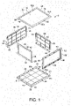
- kit of parts 2 for a display crate for protecting and displaying a pair of sneakers the assembled crate 4 being shown in Figures 2 and 3 .
- the kit 2 comprises a plurality of individual panels for adhesive-free, tool-free, snap-fit assembly together, as shown in Figure 4 , to form a self-supporting, stackable, rigid crate 4.
- the kit 2 comprises a base panel 6 having a front edge 18, a rear edge 20 and two side edges 22, 24 extending between the front and rear edges 18, 20.
- the front edge 18 has a first hinge fitting 22.
- a front door panel 26 has a second hinge fitting 28.
- the first and second hinge fittings 22, 28 are adapted to be coupled together thereby hingedly to fit a lower edge 30 of the front door panel 26 to the front edge 18 of the base panel 6.
- the first hinge fitting 22 comprises a pair of holes 32 at opposite ends of the front edge 18 of the base panel 6.
- the second hinge fitting 28 comprises a pair of pivot members 34 extending outwardly in opposite directions from opposite sides of the front door panel 26.
- the pair of pivot members 34 is separate from the front door panel 26 and the base panel 6.
- Each pivot member 34 is adapted to be inserted into a respective pair of aligned holes 32, 36 in adjacent edges 38, 40 of the front door panel 26 and the base panel 6.
- each pivot member 34 is adapted to provide a snap fit between the pivot member 34 and at least one of the front door panel 26 and the base panel 6.
- the first hinge fitting 22 comprises a pair of pivot members extending outwardly in opposite directions from opposite sides of the front door panel 26 and the second hinge fitting 28 comprises a pair of holes at opposite ends of the front edge of the base panel 6.
- the front door panel 26 has a finger recess and/or handle 42 at an upper edge 44 of the front door panel 26 to assist opening of the front door panel 26 when the display crate 4 is assembled.
- the kit 2 further comprises a pair of side panels 46, 48.
- Each side panel 46, 48 has a lower edge 50, 52 adapted to be snap-fitted to a respective one of the side edges 22, 24 of the base panel 6.
- Each side panel 48, 50 has a rear edge 54, 56 and an upper edge 58, 60.
- the kit 2 further comprises a rear panel 62.
- the rear panel 62 has a lower edge 63 adapted to be snap-fitted to the rear edge 20 of the base panel 6.
- the rear panel 62 has side edges 64, 66. Each side edge 64, 66 is adapted to be snap-fitted to the rear edge 54, 56 of a respective side panel 46, 48.
- the rear panel 62 has an upper edge 68.
- the rear edges 54, 56 of the two side panels 46, 48 each have an inwardly oriented elongate recess 70, 72 for receiving therein a respective one of the side edges 64, 66 of the rear panel 62.
- the kit 2 further comprises a top panel 74 having a front edge 76, a rear edge 78 and two side edges 80, 82 extending between the front and rear edges 76, 78.
- the rear edge 78 and the two side edges 80, 82 of the top panel 74 are adapted to be snap-fitted, respectively, to the upper edge 68 of the rear panel 62 and the upper edges 58, 60 of the pair of side panels 46, 48.
- the rear edge 20 and two side edges 22, 24 of the base panel 6 each have an upwardly oriented elongate recess 88a, 88b, 88c for receiving therein the lower edges 63, 50, 52 of the rear panel 62 and side panels 46, 48 respectively.
- the upwardly oriented elongate recesses 88a, 88b, 88c in the base panel 6 form a common U-shaped elongate recess 90 extending around the two side edges 22, 24 and the rear edge 20 of the base panel 6.
- the rear edge 78 and two side edges 80, 82 of the top panel 74 each have a downwardly oriented elongate recess 92a, 92b, 92c for receiving therein the upper edges 68, 58, 60 of the rear panel 62 and side panels 46, 48 respectively.
- the downwardly oriented elongate recesses 92a, 92b, 92c in the top panel 74 form a common U-shaped elongate recess 94 extending around the two side edges 80, 82 and the rear edge 78 of the top panel 74.
- the top panel 74 has a front stop member 84 located inwardly of the front edge 76 of the top panel 74 to act as a stop for the front door panel 26.
- the side panels 46, 48 each have a side stop member 96 located inwardly of a front edge 98 of the side panel 46, 48 to act as a stop for the front door panel 26.
- each panel is composed of an injection moulded polymer, for example polypropylene.
- the panels may be provided with internal reinforcement, such as struts or beams.
- the outside of the display crate is decorative and may be decorated with any desired two-dimensional printing or embossed surface relief.
- the display crate 4 can be formed by adhesive-free, tool-free, snap-fit assembly together of the plurality of individual panels of the kit 2.
- step I in step I as shown by arrow A, initially the base panel 6 and front door panel 26 are fitted together by coupling together the first and second hinge fittings 22, 28 by the pivot members 34 on opposite sides of the front door panel 26.
- the pivot members 34 are each inserted into the respective pair of the aligned holes 32, 36 in adjacent edges 38, 40 of the front door panel 26 and the base panel 6, and secured with a snap fit.
- step II as shown by arrows B, the pair of side panels 46, 48 are fitted to the rear panel 62.
- the side edges 64, 66 of the rear panel 62 are snap-fitted to the rear edge 54, 56 of a respective side panel 46, 48,
- step III as shown by arrows C, the lower edges 50, 52 of the side panels 46, 48 and the lower edge 63 of the rear panel 62 are snap-fitted into the common U-shaped elongate recess 90 of the base panel 6.
- step IV as shown by arrows D, the upper edges 58, 60 of the side panels 46, 48 and the upper edge 68 of the rear panel 62 rear panel 62 are snap-fitted into the common U-shaped elongate recess 94 of the top panel 74.
- the front door panel 26 can then be pivoted between open and closed positons to access or conceal sneakers with the display crate 4.
- the display crate in kit form provides the advantages that the unassembled kit can be shipped and sold at minimal shipping cost. However, the consumer and purchaser can readily manually assemble the display crate at home from the kit without using adhesive or any tools.
- the display crate can be assembled in only about 20 seconds.
- the resultant display crate is robust, self-supporting, stackable and rigid. The robustness may be enhanced by making each panel from injection moulded polymer, with optional internal reinforcement.
Landscapes
- Engineering & Computer Science (AREA)
- Mechanical Engineering (AREA)
- Details Of Rigid Or Semi-Rigid Containers (AREA)
- Rigid Containers With Two Or More Constituent Elements (AREA)
- Cartons (AREA)
- Telephone Set Structure (AREA)
- Assembled Shelves (AREA)
Claims (14)
- Bausatz von Teilen (2) für eine Ausstellungskiste zum Schützen und Ausstellen eines Paares von Turnschuhen, wobei der Bausatz mehrere einzelne Platten für einen klebstofffreien, werkzeuglosen Einrast-Zusammenbau aufweist, um eine selbsttragende, stapelbare, starre Kiste zu bilden, wobei der Bausatz aufweist:(i) eine Bodenplatte (6) mit einer Vorderkante (18), einer Hinterkante (20) und zwei sich zwischen den Vorder- und Hinterkanten erstreckenden Seitenkanten (22, 24);(ii) eine vordere Türplatte (26);(iii) ein Paar von Seitenplatten (46, 48), wobei jede Seitenplatte eine Unterkante (50, 52) hat, die angepasst ist, um an eine jeweilige der Seitenkanten der Bodenplatte eingerastet zu werden, wobei jede Seitenplatte eine Hinterkante (54, 56) und eine Oberkante (58, 60) hat;(iv) eine Rückplatte (62), wobei die Rückplatte eine Unterkante (63) hat, die angepasst ist, um an die Hinterkante der Bodenplatte eingerastet zu werden, und wobei die Rückplatte Seitenkanten (64, 66), wobei jede Seitenkante angepasst ist, um an die Hinterkante einer jeweiligen Seitenplatte eingerastet zu werden, und eine Oberkante (68) hat; und(v) eine Oberplatte (74) mit einer Vorderkante (76), einer Hinterkante (78) und zwei sich zwischen den Vorder- und Hinterkanten erstreckenden Seitenkanten (80, 82), wobei die Hinterkante und die zwei Seitenkanten der Oberplatte angepasst sind, um an die Oberkante der Rückplatte bzw. die Oberkanten des Paares der Seitenplatten eingerastet zu werden;dadurch gekennzeichnet, dassdie Hinterkante und die zwei Seitenkanten der Bodenplatte jeweils eine nach oben gerichtete längliche Aussparung (88a, 88b, 88c) haben, die darin die Unterkanten der Rückplatte bzw. der Seitenplatten aufnimmt, wobei die Hinterkanten der beiden Seitenplatten jeweils eine nach innen gerichtete längliche Aussparung (70, 72) haben, die darin eine jeweilige der Seitenkanten der Rückplatte aufnimmt, und die Hinterkante und die zwei Seitenkanten der Oberplatte jeweils eine nach unten gerichtete längliche Aussparung (92a, 92b, 92c) haben, die darin die Oberkanten der Rückplatte bzw. der Seitenplatten aufnimmt; unddie Vorderkante (18) der Bodenplatte (6) einen ersten Scharnierbeschlag (22) hat, die vordere Türplatte (26) einen zweiten Scharnierbeschlag (28) hat, und die ersten und zweiten Scharnierbeschläge (22, 28) angepasst sind, um dadurch scharnierartig aneinander gekoppelt zu sein, um eine Unterkante (30) der vorderen Türplatte (26) an der Vorderkante (18) der Bodenplatte (6) anzubringen.
- Bausatz (2) nach Anspruch 1, wobei: i) der erste Scharnierbeschlag (22) ein Paar Löcher (32) an gegenüberliegenden Enden der Vorderkante (18) der Bodenplatte (6) aufweist und der zweite Scharnierbeschlag (28) ein Paar Schwenkelemente (34) aufweist, die sich von gegenüberliegenden Seiten der vorderen Türplatte (26) in entgegengesetzten Richtungen nach außen erstrecken; oder ii) der erste Scharnierbeschlag ein Paar Schwenkelemente aufweist, die sich von gegenüberliegenden Seiten der vorderen Türplatte in entgegengesetzten Richtungen nach außen erstrecken, und der zweite Scharnierbeschlag ein Paar Löcher an gegenüberliegenden Enden der Vorderkante der Bodenplatte aufweist.
- Bausatz (2) nach Anspruch 2, wobei jedes Schwenkelement (34) angepasst ist, um eine Einrastverbindung zwischen dem Schwenkelement und der vorderen Türplatte (26) und der Bodenplatte (6) zu schaffen.
- Bausatz (2) nach einem der vorhergehenden Ansprüche, wobei die vordere Türplatte (26) eine Fingeraussparung und/oder einen Griff (42) an einer Oberkante (44) der vorderen Türplatte hat.
- Bausatz (2) nach einem der vorhergehenden Ansprüche, wobei: i) die nach oben gerichteten länglichen Aussparungen (88a, 88b, 88c) in der Bodenplatte (6) eine gemeinsame U-förmige längliche Aussparung (90) bilden, die sich um die zwei Seitenkanten (22, 24) und die Hinterkante (20) der Bodenplatte erstreckt; und/oder ii) die nach unten gerichteten länglichen Aussparungen (92a, 92b, 92c) in der Oberplatte (74) eine gemeinsame U-förmige längliche Aussparung (94) bilden, die sich um die zwei Seitenkanten (80, 82) und die Hinterkante (78) der Oberplatte erstreckt.
- Bausatz (2) nach einem der vorhergehenden Ansprüche, wobei: i) die Seitenplatten (46, 48) jeweils ein Seitenanschlagelement (96) haben, das sich von einer Vorderkante (98) der Seitenplatte nach innen befindet, um als ein Anschlag für die vordere Türplatte (26) zu wirken; und/oder ii) die Oberplatte (74) ein Vorderanschlagelement (84) hat, das sich von einer Vorderkante (76) der Oberplatte nach innen befindet, um als ein Anschlag für die vordere Türplatte zu wirken.
- Bausatz (2) nach einem der vorhergehenden Ansprüche, wobei jede Platte (6, 26, 46, 48, 62, 74) aus einem spritzgegossenen Polymer besteht.
- Ausstellungskiste (4) zum Schützen und Ausstellen eines Paares von Turnschuhen, wobei die Ausstellungskiste mehrere einzelne Platten aufweist, die durch einen klebstofffreien, werkzeuglosen Einrast-Zusammenbau zusammengebaut sind, um eine selbsttragende, stapelbare, starre Kiste zu bilden, wobei die Kiste aufweist:(i) eine Bodenplatte (6) mit einer Vorderkante (18), einer Hinterkante (20) und zwei sich zwischen den Vorder- und Hinterkanten erstreckenden Seitenkanten (22, 24);(ii) eine vordere Türplatte (26);(iii) ein Paar von Seitenplatten (46, 48), wobei jede Seitenplatte eine Unterkante (50, 52) hat, die an eine jeweilige der Seitenkanten der Bodenplatte eingerastet ist, wobei jede Seitenplatte eine Hinterkante (54, 56) und eine Oberkante (58, 60) hat;(iv) eine Rückplatte (62), wobei die Rückplatte eine Unterkante (63) hat, die an die Hinterkante der Bodenplatte eingerastet ist, und wobei die Rückplatte Seitenkanten (64, 66), wobei jede Seitenkante an die Hinterkante einer jeweiligen Seitenplatte eingerastet ist, und eine Oberkante (68) hat; und(v) eine Oberplatte (74) mit einer Vorderkante (76), einer Hinterkante (78) und zwei sich zwischen den Vorder- und Hinterkanten erstreckenden Seitenkanten (80, 82), wobei die Hinterkante und die zwei Seitenkanten der Oberplatte an die Oberkante der Rückplatte bzw. die Oberkanten des Paares der Seitenplatten eingerastet sind,dadurch gekennzeichnet, dassdie Hinterkante und die zwei Seitenkanten der Bodenplatte jeweils eine nach oben gerichtete längliche Aussparung (88a, 88b, 88c) haben, die darin die Unterkanten der Rückplatte bzw. der Seitenplatten aufnimmt, wobei die Hinterkanten der beiden Seitenplatten jeweils eine nach innen gerichtete längliche Aussparung (70, 72) haben, die darin eine jeweilige der Seitenkanten der Rückplatte aufnimmt, und die Hinterkante und die zwei Seitenkanten der Oberplatte jeweils eine nach unten gerichtete längliche Aussparung (92a, 92b, 92c) haben, die darin die Oberkanten der Rückplatte bzw. der Seitenplatten aufnimmt; unddie Vorderkante (18) der Bodenplatte (6) einen ersten Scharnierbeschlag (22) hat, die vordere Türplatte (26) einen zweiten Scharnierbeschlag (28) hat, und die ersten und zweiten Scharnierbeschläge (22, 28) angepasst sind, um dadurch scharnierartig aneinander gekoppelt zu sein, um eine Unterkante (30) der vorderen Türplatte (26) an der Vorderkante (18) der Bodenplatte (6) anzubringen.
- Ausstellungskiste (4) nach Anspruch 8, wobei: i) der erste Scharnierbeschlag (22) ein Paar Löcher (32) an gegenüberliegenden Enden der Vorderkante (18) der Bodenplatte (6) aufweist und der zweite Scharnierbeschlag (28) ein Paar Schwenkelemente (34) aufweist, die sich von gegenüberliegenden Seiten der vorderen Türplatte (26) in entgegengesetzten Richtungen nach außen erstrecken; oder ii) der erste Scharnierbeschlag ein Paar Schwenkelemente aufweist, die sich von gegenüberliegenden Seiten der vorderen Türplatte in entgegengesetzten Richtungen nach außen erstrecken, und der zweite Scharnierbeschlag ein Paar Löcher an gegenüberliegenden Enden der Vorderkante der Bodenplatte aufweist.
- Ausstellungskiste (4) nach Anspruch 9, wobei das Paar Schwenkelemente (34) an der vorderen Türplatte (26) und der Bodenplatte (6) eingerastet ist und jedes Schwenkelement in ein jeweiliges Paar ausgerichteter Löcher (32, 36) in benachbarten Kanten (38, 40) der vorderen Türplatte und der Bodenplatte eingesetzt ist, wobei optional jedes Schwenkelement eine Einrastverbindung zwischen dem Schwenkelement und der vorderen Türplatte und der Bodenplatte schafft.
- Ausstellungskiste (4) nach einem der Ansprüche 8 bis 10, wobei die vordere Türplatte (26) eine Fingeraussparung und/oder einen Griff (42) an einer Oberkante (44) der vorderen Türplatte hat.
- Ausstellungskiste (4) nach einem der Ansprüche 9 bis 11, wobei: i) die nach oben gerichteten länglichen Aussparungen (88a, 88b, 88c) in der Bodenplatte (6) eine gemeinsame U-förmige längliche Aussparung (90) bilden, die sich um die zwei Seitenkanten (22, 24) und die Hinterkante (20) der Bodenplatte erstreckt; und/oder ii) die nach unten gerichteten länglichen Aussparungen (92a, 92b, 92c) in der Oberplatte (74) eine gemeinsame U-förmige längliche Aussparung (94) bilden, die sich um die zwei Seitenkanten (80, 82) und die Hinterkante (78) der Oberplatte erstreckt.
- Ausstellungskiste (4) nach einem der Ansprüche 8 bis 12, wobei: i) die Seitenplatten (46, 48) jeweils ein sich von einer Vorderkante (98) der Seitenplatte nach innen befindendes Seitenanschlagelement (96) haben, welches als ein Anschlag für die vordere Türplatte (26) wirkt; und/oder ii) die Oberplatte (74) ein sich von einer Vorderkante (76) der Oberplatte nach innen befindendes Vorderanschlagelement (84) hat, welches als ein Anschlag für die vordere Türplatte wirkt.
- Ausstellungskiste (4) nach einem der Ansprüche 8 bis 13, wobei jede Platte (6, 26, 46, 48, 62, 74) aus einem spritzgegossenen Polymer besteht.
Applications Claiming Priority (2)
| Application Number | Priority Date | Filing Date | Title |
|---|---|---|---|
| GB1707644.9A GB2562303B (en) | 2017-05-12 | 2017-05-12 | Display crate and kit of parts therefor |
| PCT/EP2018/062263 WO2018206800A1 (en) | 2017-05-12 | 2018-05-11 | Display crate and kit of parts therefor |
Publications (2)
| Publication Number | Publication Date |
|---|---|
| EP3609796A1 EP3609796A1 (de) | 2020-02-19 |
| EP3609796B1 true EP3609796B1 (de) | 2023-01-25 |
Family
ID=59201730
Family Applications (1)
| Application Number | Title | Priority Date | Filing Date |
|---|---|---|---|
| EP18724233.4A Active EP3609796B1 (de) | 2017-05-12 | 2018-05-11 | Schaukasten und teilesatz dafür |
Country Status (9)
| Country | Link |
|---|---|
| US (1) | US20200385167A1 (de) |
| EP (1) | EP3609796B1 (de) |
| CN (1) | CN110177743A (de) |
| ES (1) | ES2940382T3 (de) |
| GB (1) | GB2562303B (de) |
| MY (1) | MY198595A (de) |
| PL (1) | PL3609796T3 (de) |
| SG (1) | SG11201909164QA (de) |
| WO (1) | WO2018206800A1 (de) |
Families Citing this family (8)
| Publication number | Priority date | Publication date | Assignee | Title |
|---|---|---|---|---|
| ES2942233T3 (es) | 2017-08-30 | 2023-05-30 | Luhao Leng | Caja de almacenamiento con al menos un panel lateral de plástico reforzado |
| WO2019042242A1 (zh) | 2017-08-30 | 2019-03-07 | 冷鹭浩 | 复合结构板 |
| EP4474604B1 (de) * | 2018-04-03 | 2025-12-17 | New-Tec Integration (Xiamen) Co., Ltd. | Zusammensetzbarer aufbewahrungsbehälter |
| US11869389B2 (en) * | 2018-12-14 | 2024-01-09 | Tradeshow Fairy Llc | Tradeshow display crate |
| CN111717507A (zh) * | 2020-06-04 | 2020-09-29 | 内蒙古自然博物馆 | 博物馆组合式化石运输展示箱及运输展示方法 |
| US11834249B2 (en) * | 2020-07-07 | 2023-12-05 | Sgcc Inc. | Apparatus and system for authenticating, grading, and encapsulating collectibles |
| USD1086719S1 (en) * | 2022-09-12 | 2025-08-05 | L&F Plastics, Co., Ltd. | Lid for storage box |
| USD1078280S1 (en) * | 2022-09-12 | 2025-06-10 | L&F Plastics, Co., Ltd. | Frame for storage box |
Family Cites Families (8)
| Publication number | Priority date | Publication date | Assignee | Title |
|---|---|---|---|---|
| CH430565A (de) * | 1965-07-30 | 1967-02-15 | Holzwerte Ag | Nagellose Kiste |
| US5197661A (en) * | 1992-06-03 | 1993-03-30 | Sanchez Martha L | See-through storage container |
| US6557955B2 (en) * | 2001-01-13 | 2003-05-06 | Darren Saravis | Snap together modular storage |
| EP1893499A4 (de) * | 2005-05-31 | 2009-06-03 | Life Order Products Pty Ltd | Stapelbare lagerungskiste |
| DE202007000545U1 (de) * | 2007-01-13 | 2007-04-19 | Schoeni, Christiane | Modulares Aufbewahrungssystem von Schuhen |
| CN201313660Y (zh) * | 2008-09-22 | 2009-09-23 | 福建振云塑业股份有限公司 | 拼装式文件箱 |
| IES20090539A2 (en) * | 2009-07-15 | 2011-01-19 | Joseph Patrick Kelly | A storage device and storage system |
| CN205738800U (zh) * | 2016-05-06 | 2016-11-30 | 江西太平洋电缆集团有限公司 | 一种塑料鞋盒 |
-
2017
- 2017-05-12 GB GB1707644.9A patent/GB2562303B/en not_active Expired - Fee Related
-
2018
- 2018-05-11 ES ES18724233T patent/ES2940382T3/es active Active
- 2018-05-11 EP EP18724233.4A patent/EP3609796B1/de active Active
- 2018-05-11 WO PCT/EP2018/062263 patent/WO2018206800A1/en not_active Ceased
- 2018-05-11 US US16/482,705 patent/US20200385167A1/en not_active Abandoned
- 2018-05-11 MY MYPI2019006342A patent/MY198595A/en unknown
- 2018-05-11 SG SG11201909164Q patent/SG11201909164QA/en unknown
- 2018-05-11 CN CN201880004589.9A patent/CN110177743A/zh active Pending
- 2018-05-11 PL PL18724233.4T patent/PL3609796T3/pl unknown
Also Published As
| Publication number | Publication date |
|---|---|
| EP3609796A1 (de) | 2020-02-19 |
| CN110177743A (zh) | 2019-08-27 |
| US20200385167A1 (en) | 2020-12-10 |
| ES2940382T3 (es) | 2023-05-05 |
| PL3609796T3 (pl) | 2023-05-08 |
| MY198595A (en) | 2023-09-07 |
| GB2562303B (en) | 2019-10-16 |
| WO2018206800A1 (en) | 2018-11-15 |
| GB201707644D0 (en) | 2017-06-28 |
| SG11201909164QA (en) | 2019-10-30 |
| GB2562303A (en) | 2018-11-14 |
Similar Documents
| Publication | Publication Date | Title |
|---|---|---|
| US20200385167A1 (en) | Display crate and kit of parts therefor | |
| US5934551A (en) | Four pack display container | |
| US4925087A (en) | Packaging container with display window | |
| US20090272658A1 (en) | Box with a-frame product support | |
| US9301603B1 (en) | Collapsible storage cabinet | |
| US5706953A (en) | Combination shipping carton and display stand formed with insert panels and shelves | |
| US8328016B2 (en) | Display package | |
| US7874430B2 (en) | Product container assembly with product window | |
| US4258842A (en) | Cap display package | |
| US6926152B2 (en) | Display and carrying case for a doll and doll accessories | |
| US6726019B2 (en) | Display and carrying case for a doll and doll accessories | |
| US7258265B2 (en) | Point of purchase display carton | |
| EP2576366B1 (de) | Zerlegbares fass und verfahren zur montage | |
| US20140318999A1 (en) | Packaging and Methods for Displaying Tools | |
| US20090057174A1 (en) | Container | |
| US20070235963A1 (en) | Interchangeable and nestable storage bin and lid | |
| KR101316849B1 (ko) | 진열형 포장박스 | |
| KR101994868B1 (ko) | 포장상자 | |
| KR200320551Y1 (ko) | 상품 진열 상자 | |
| JP3140687B2 (ja) | 物品の包装用箱にも兼用可能な物品展示用具 | |
| US20060219763A1 (en) | Generally pyramidal packaging box | |
| WO2011099163A1 (ja) | 履物用段ボール箱及び履物用段ボール箱の組立体 | |
| RU2788257C1 (ru) | Дополнительное место продажи | |
| US20060284521A1 (en) | Tray and drawer system | |
| KR20010083307A (ko) | 휴대가 가능한 물품 포장상자 |
Legal Events
| Date | Code | Title | Description |
|---|---|---|---|
| STAA | Information on the status of an ep patent application or granted ep patent |
Free format text: STATUS: UNKNOWN |
|
| STAA | Information on the status of an ep patent application or granted ep patent |
Free format text: STATUS: THE INTERNATIONAL PUBLICATION HAS BEEN MADE |
|
| PUAI | Public reference made under article 153(3) epc to a published international application that has entered the european phase |
Free format text: ORIGINAL CODE: 0009012 |
|
| STAA | Information on the status of an ep patent application or granted ep patent |
Free format text: STATUS: REQUEST FOR EXAMINATION WAS MADE |
|
| 17P | Request for examination filed |
Effective date: 20191113 |
|
| AK | Designated contracting states |
Kind code of ref document: A1 Designated state(s): AL AT BE BG CH CY CZ DE DK EE ES FI FR GB GR HR HU IE IS IT LI LT LU LV MC MK MT NL NO PL PT RO RS SE SI SK SM TR |
|
| AX | Request for extension of the european patent |
Extension state: BA ME |
|
| DAV | Request for validation of the european patent (deleted) | ||
| DAX | Request for extension of the european patent (deleted) | ||
| STAA | Information on the status of an ep patent application or granted ep patent |
Free format text: STATUS: EXAMINATION IS IN PROGRESS |
|
| REG | Reference to a national code |
Ref country code: HK Ref legal event code: DE Ref document number: 40023892 Country of ref document: HK |
|
| 17Q | First examination report despatched |
Effective date: 20201113 |
|
| GRAP | Despatch of communication of intention to grant a patent |
Free format text: ORIGINAL CODE: EPIDOSNIGR1 |
|
| STAA | Information on the status of an ep patent application or granted ep patent |
Free format text: STATUS: GRANT OF PATENT IS INTENDED |
|
| INTG | Intention to grant announced |
Effective date: 20220818 |
|
| GRAS | Grant fee paid |
Free format text: ORIGINAL CODE: EPIDOSNIGR3 |
|
| GRAA | (expected) grant |
Free format text: ORIGINAL CODE: 0009210 |
|
| STAA | Information on the status of an ep patent application or granted ep patent |
Free format text: STATUS: THE PATENT HAS BEEN GRANTED |
|
| RBV | Designated contracting states (corrected) |
Designated state(s): AL AT BE BG CH CY CZ DE DK EE ES FI FR GR HR HU IE IS IT LI LT LU LV MC MK MT NL NO PL PT RO RS SE SI SK SM TR |
|
| AK | Designated contracting states |
Kind code of ref document: B1 Designated state(s): AL AT BE BG CH CY CZ DE DK EE ES FI FR GR HR HU IE IS IT LI LT LU LV MC MK MT NL NO PL PT RO RS SE SI SK SM TR |
|
| REG | Reference to a national code |
Ref country code: CH Ref legal event code: EP |
|
| REG | Reference to a national code |
Ref country code: DE Ref legal event code: R096 Ref document number: 602018045714 Country of ref document: DE |
|
| REG | Reference to a national code |
Ref country code: AT Ref legal event code: REF Ref document number: 1545771 Country of ref document: AT Kind code of ref document: T Effective date: 20230215 Ref country code: IE Ref legal event code: FG4D |
|
| REG | Reference to a national code |
Ref country code: NL Ref legal event code: FP |
|
| REG | Reference to a national code |
Ref country code: ES Ref legal event code: FG2A Ref document number: 2940382 Country of ref document: ES Kind code of ref document: T3 Effective date: 20230505 |
|
| REG | Reference to a national code |
Ref country code: LT Ref legal event code: MG9D |
|
| REG | Reference to a national code |
Ref country code: GR Ref legal event code: EP Ref document number: 20230400531 Country of ref document: GR Effective date: 20230510 |
|
| REG | Reference to a national code |
Ref country code: AT Ref legal event code: MK05 Ref document number: 1545771 Country of ref document: AT Kind code of ref document: T Effective date: 20230125 |
|
| PG25 | Lapsed in a contracting state [announced via postgrant information from national office to epo] |
Ref country code: RS Free format text: LAPSE BECAUSE OF FAILURE TO SUBMIT A TRANSLATION OF THE DESCRIPTION OR TO PAY THE FEE WITHIN THE PRESCRIBED TIME-LIMIT Effective date: 20230125 Ref country code: PT Free format text: LAPSE BECAUSE OF FAILURE TO SUBMIT A TRANSLATION OF THE DESCRIPTION OR TO PAY THE FEE WITHIN THE PRESCRIBED TIME-LIMIT Effective date: 20230525 Ref country code: NO Free format text: LAPSE BECAUSE OF FAILURE TO SUBMIT A TRANSLATION OF THE DESCRIPTION OR TO PAY THE FEE WITHIN THE PRESCRIBED TIME-LIMIT Effective date: 20230425 Ref country code: LV Free format text: LAPSE BECAUSE OF FAILURE TO SUBMIT A TRANSLATION OF THE DESCRIPTION OR TO PAY THE FEE WITHIN THE PRESCRIBED TIME-LIMIT Effective date: 20230125 Ref country code: LT Free format text: LAPSE BECAUSE OF FAILURE TO SUBMIT A TRANSLATION OF THE DESCRIPTION OR TO PAY THE FEE WITHIN THE PRESCRIBED TIME-LIMIT Effective date: 20230125 Ref country code: HR Free format text: LAPSE BECAUSE OF FAILURE TO SUBMIT A TRANSLATION OF THE DESCRIPTION OR TO PAY THE FEE WITHIN THE PRESCRIBED TIME-LIMIT Effective date: 20230125 Ref country code: AT Free format text: LAPSE BECAUSE OF FAILURE TO SUBMIT A TRANSLATION OF THE DESCRIPTION OR TO PAY THE FEE WITHIN THE PRESCRIBED TIME-LIMIT Effective date: 20230125 |
|
| PG25 | Lapsed in a contracting state [announced via postgrant information from national office to epo] |
Ref country code: SE Free format text: LAPSE BECAUSE OF FAILURE TO SUBMIT A TRANSLATION OF THE DESCRIPTION OR TO PAY THE FEE WITHIN THE PRESCRIBED TIME-LIMIT Effective date: 20230125 Ref country code: IS Free format text: LAPSE BECAUSE OF FAILURE TO SUBMIT A TRANSLATION OF THE DESCRIPTION OR TO PAY THE FEE WITHIN THE PRESCRIBED TIME-LIMIT Effective date: 20230525 Ref country code: FI Free format text: LAPSE BECAUSE OF FAILURE TO SUBMIT A TRANSLATION OF THE DESCRIPTION OR TO PAY THE FEE WITHIN THE PRESCRIBED TIME-LIMIT Effective date: 20230125 |
|
| REG | Reference to a national code |
Ref country code: DE Ref legal event code: R097 Ref document number: 602018045714 Country of ref document: DE |
|
| PG25 | Lapsed in a contracting state [announced via postgrant information from national office to epo] |
Ref country code: SM Free format text: LAPSE BECAUSE OF FAILURE TO SUBMIT A TRANSLATION OF THE DESCRIPTION OR TO PAY THE FEE WITHIN THE PRESCRIBED TIME-LIMIT Effective date: 20230125 Ref country code: RO Free format text: LAPSE BECAUSE OF FAILURE TO SUBMIT A TRANSLATION OF THE DESCRIPTION OR TO PAY THE FEE WITHIN THE PRESCRIBED TIME-LIMIT Effective date: 20230125 Ref country code: EE Free format text: LAPSE BECAUSE OF FAILURE TO SUBMIT A TRANSLATION OF THE DESCRIPTION OR TO PAY THE FEE WITHIN THE PRESCRIBED TIME-LIMIT Effective date: 20230125 Ref country code: DK Free format text: LAPSE BECAUSE OF FAILURE TO SUBMIT A TRANSLATION OF THE DESCRIPTION OR TO PAY THE FEE WITHIN THE PRESCRIBED TIME-LIMIT Effective date: 20230125 Ref country code: CZ Free format text: LAPSE BECAUSE OF FAILURE TO SUBMIT A TRANSLATION OF THE DESCRIPTION OR TO PAY THE FEE WITHIN THE PRESCRIBED TIME-LIMIT Effective date: 20230125 |
|
| REG | Reference to a national code |
Ref country code: HK Ref legal event code: WD Ref document number: 40023892 Country of ref document: HK |
|
| PG25 | Lapsed in a contracting state [announced via postgrant information from national office to epo] |
Ref country code: SK Free format text: LAPSE BECAUSE OF FAILURE TO SUBMIT A TRANSLATION OF THE DESCRIPTION OR TO PAY THE FEE WITHIN THE PRESCRIBED TIME-LIMIT Effective date: 20230125 Ref country code: AL Free format text: LAPSE BECAUSE OF FAILURE TO SUBMIT A TRANSLATION OF THE DESCRIPTION OR TO PAY THE FEE WITHIN THE PRESCRIBED TIME-LIMIT Effective date: 20230125 |
|
| PLBE | No opposition filed within time limit |
Free format text: ORIGINAL CODE: 0009261 |
|
| STAA | Information on the status of an ep patent application or granted ep patent |
Free format text: STATUS: NO OPPOSITION FILED WITHIN TIME LIMIT |
|
| REG | Reference to a national code |
Ref country code: CH Ref legal event code: PL |
|
| 26N | No opposition filed |
Effective date: 20231026 |
|
| PG25 | Lapsed in a contracting state [announced via postgrant information from national office to epo] |
Ref country code: MC Free format text: LAPSE BECAUSE OF FAILURE TO SUBMIT A TRANSLATION OF THE DESCRIPTION OR TO PAY THE FEE WITHIN THE PRESCRIBED TIME-LIMIT Effective date: 20230125 |
|
| REG | Reference to a national code |
Ref country code: BE Ref legal event code: MM Effective date: 20230531 |
|
| PG25 | Lapsed in a contracting state [announced via postgrant information from national office to epo] |
Ref country code: SI Free format text: LAPSE BECAUSE OF FAILURE TO SUBMIT A TRANSLATION OF THE DESCRIPTION OR TO PAY THE FEE WITHIN THE PRESCRIBED TIME-LIMIT Effective date: 20230125 Ref country code: MC Free format text: LAPSE BECAUSE OF FAILURE TO SUBMIT A TRANSLATION OF THE DESCRIPTION OR TO PAY THE FEE WITHIN THE PRESCRIBED TIME-LIMIT Effective date: 20230125 Ref country code: LU Free format text: LAPSE BECAUSE OF NON-PAYMENT OF DUE FEES Effective date: 20230511 Ref country code: LI Free format text: LAPSE BECAUSE OF NON-PAYMENT OF DUE FEES Effective date: 20230531 Ref country code: CH Free format text: LAPSE BECAUSE OF NON-PAYMENT OF DUE FEES Effective date: 20230531 |
|
| REG | Reference to a national code |
Ref country code: IE Ref legal event code: MM4A |
|
| PG25 | Lapsed in a contracting state [announced via postgrant information from national office to epo] |
Ref country code: IE Free format text: LAPSE BECAUSE OF NON-PAYMENT OF DUE FEES Effective date: 20230511 |
|
| PG25 | Lapsed in a contracting state [announced via postgrant information from national office to epo] |
Ref country code: IE Free format text: LAPSE BECAUSE OF NON-PAYMENT OF DUE FEES Effective date: 20230511 |
|
| PG25 | Lapsed in a contracting state [announced via postgrant information from national office to epo] |
Ref country code: BE Free format text: LAPSE BECAUSE OF NON-PAYMENT OF DUE FEES Effective date: 20230531 |
|
| PGFP | Annual fee paid to national office [announced via postgrant information from national office to epo] |
Ref country code: DE Payment date: 20240521 Year of fee payment: 7 |
|
| PGFP | Annual fee paid to national office [announced via postgrant information from national office to epo] |
Ref country code: GR Payment date: 20240523 Year of fee payment: 7 |
|
| PGFP | Annual fee paid to national office [announced via postgrant information from national office to epo] |
Ref country code: NL Payment date: 20240529 Year of fee payment: 7 |
|
| PGFP | Annual fee paid to national office [announced via postgrant information from national office to epo] |
Ref country code: ES Payment date: 20240603 Year of fee payment: 7 |
|
| PGFP | Annual fee paid to national office [announced via postgrant information from national office to epo] |
Ref country code: FR Payment date: 20240528 Year of fee payment: 7 |
|
| PGFP | Annual fee paid to national office [announced via postgrant information from national office to epo] |
Ref country code: PL Payment date: 20240510 Year of fee payment: 7 |
|
| PGFP | Annual fee paid to national office [announced via postgrant information from national office to epo] |
Ref country code: IT Payment date: 20240522 Year of fee payment: 7 |
|
| PG25 | Lapsed in a contracting state [announced via postgrant information from national office to epo] |
Ref country code: BG Free format text: LAPSE BECAUSE OF FAILURE TO SUBMIT A TRANSLATION OF THE DESCRIPTION OR TO PAY THE FEE WITHIN THE PRESCRIBED TIME-LIMIT Effective date: 20230125 |
|
| PG25 | Lapsed in a contracting state [announced via postgrant information from national office to epo] |
Ref country code: BG Free format text: LAPSE BECAUSE OF FAILURE TO SUBMIT A TRANSLATION OF THE DESCRIPTION OR TO PAY THE FEE WITHIN THE PRESCRIBED TIME-LIMIT Effective date: 20230125 |
|
| PG25 | Lapsed in a contracting state [announced via postgrant information from national office to epo] |
Ref country code: CY Free format text: LAPSE BECAUSE OF FAILURE TO SUBMIT A TRANSLATION OF THE DESCRIPTION OR TO PAY THE FEE WITHIN THE PRESCRIBED TIME-LIMIT; INVALID AB INITIO Effective date: 20180511 |
|
| PG25 | Lapsed in a contracting state [announced via postgrant information from national office to epo] |
Ref country code: HU Free format text: LAPSE BECAUSE OF FAILURE TO SUBMIT A TRANSLATION OF THE DESCRIPTION OR TO PAY THE FEE WITHIN THE PRESCRIBED TIME-LIMIT; INVALID AB INITIO Effective date: 20180511 |
|
| REG | Reference to a national code |
Ref country code: DE Ref legal event code: R119 Ref document number: 602018045714 Country of ref document: DE |
|
| PG25 | Lapsed in a contracting state [announced via postgrant information from national office to epo] |
Ref country code: TR Free format text: LAPSE BECAUSE OF FAILURE TO SUBMIT A TRANSLATION OF THE DESCRIPTION OR TO PAY THE FEE WITHIN THE PRESCRIBED TIME-LIMIT Effective date: 20230125 |
|
| REG | Reference to a national code |
Ref country code: NL Ref legal event code: MM Effective date: 20250601 |
|
| PG25 | Lapsed in a contracting state [announced via postgrant information from national office to epo] |
Ref country code: GR Free format text: LAPSE BECAUSE OF NON-PAYMENT OF DUE FEES Effective date: 20251205 |
|
| PG25 | Lapsed in a contracting state [announced via postgrant information from national office to epo] |
Ref country code: NL Free format text: LAPSE BECAUSE OF NON-PAYMENT OF DUE FEES Effective date: 20250601 |
|
| PG25 | Lapsed in a contracting state [announced via postgrant information from national office to epo] |
Ref country code: DE Free format text: LAPSE BECAUSE OF NON-PAYMENT OF DUE FEES Effective date: 20251202 |
|
| PG25 | Lapsed in a contracting state [announced via postgrant information from national office to epo] |
Ref country code: IT Free format text: LAPSE BECAUSE OF NON-PAYMENT OF DUE FEES Effective date: 20250511 |
|
| PG25 | Lapsed in a contracting state [announced via postgrant information from national office to epo] |
Ref country code: FR Free format text: LAPSE BECAUSE OF NON-PAYMENT OF DUE FEES Effective date: 20250531 |