EP3608933A1 - Schutzschalter mit schnappkontakten - Google Patents
Schutzschalter mit schnappkontakten Download PDFInfo
- Publication number
- EP3608933A1 EP3608933A1 EP18214873.4A EP18214873A EP3608933A1 EP 3608933 A1 EP3608933 A1 EP 3608933A1 EP 18214873 A EP18214873 A EP 18214873A EP 3608933 A1 EP3608933 A1 EP 3608933A1
- Authority
- EP
- European Patent Office
- Prior art keywords
- moveable contact
- contact
- moveable
- contact arm
- linkage
- Prior art date
- Legal status (The legal status is an assumption and is not a legal conclusion. Google has not performed a legal analysis and makes no representation as to the accuracy of the status listed.)
- Granted
Links
Images


Classifications
-
- H—ELECTRICITY
- H01—ELECTRIC ELEMENTS
- H01H—ELECTRIC SWITCHES; RELAYS; SELECTORS; EMERGENCY PROTECTIVE DEVICES
- H01H71/00—Details of the protective switches or relays covered by groups H01H73/00 - H01H83/00
- H01H71/10—Operating or release mechanisms
- H01H71/50—Manual reset mechanisms which may be also used for manual release
- H01H71/505—Latching devices between operating and release mechanism
-
- H—ELECTRICITY
- H01—ELECTRIC ELEMENTS
- H01H—ELECTRIC SWITCHES; RELAYS; SELECTORS; EMERGENCY PROTECTIVE DEVICES
- H01H73/00—Protective overload circuit-breaking switches in which excess current opens the contacts by automatic release of mechanical energy stored by previous operation of a hand reset mechanism
- H01H73/02—Details
- H01H73/04—Contacts
-
- H—ELECTRICITY
- H01—ELECTRIC ELEMENTS
- H01H—ELECTRIC SWITCHES; RELAYS; SELECTORS; EMERGENCY PROTECTIVE DEVICES
- H01H9/00—Details of switching devices, not covered by groups H01H1/00 - H01H7/00
- H01H9/30—Means for extinguishing or preventing arc between current-carrying parts
- H01H9/34—Stationary parts for restricting or subdividing the arc, e.g. barrier plate
-
- H—ELECTRICITY
- H01—ELECTRIC ELEMENTS
- H01H—ELECTRIC SWITCHES; RELAYS; SELECTORS; EMERGENCY PROTECTIVE DEVICES
- H01H5/00—Snap-action arrangements, i.e. in which during a single opening operation or a single closing operation energy is first stored and then released to produce or assist the contact movement
- H01H5/04—Energy stored by deformation of elastic members
- H01H5/06—Energy stored by deformation of elastic members by compression or extension of coil springs
- H01H5/08—Energy stored by deformation of elastic members by compression or extension of coil springs one end of spring transmitting movement to the contact member when the other end is moved by the operating part
-
- H—ELECTRICITY
- H01—ELECTRIC ELEMENTS
- H01H—ELECTRIC SWITCHES; RELAYS; SELECTORS; EMERGENCY PROTECTIVE DEVICES
- H01H71/00—Details of the protective switches or relays covered by groups H01H73/00 - H01H83/00
- H01H71/02—Housings; Casings; Bases; Mountings
- H01H71/0264—Mountings or coverplates for complete assembled circuit breakers, e.g. snap mounting in panel
-
- H—ELECTRICITY
- H01—ELECTRIC ELEMENTS
- H01H—ELECTRIC SWITCHES; RELAYS; SELECTORS; EMERGENCY PROTECTIVE DEVICES
- H01H73/00—Protective overload circuit-breaking switches in which excess current opens the contacts by automatic release of mechanical energy stored by previous operation of a hand reset mechanism
- H01H73/02—Details
- H01H73/18—Means for extinguishing or suppressing arc
-
- H—ELECTRICITY
- H01—ELECTRIC ELEMENTS
- H01H—ELECTRIC SWITCHES; RELAYS; SELECTORS; EMERGENCY PROTECTIVE DEVICES
- H01H83/00—Protective switches, e.g. circuit-breaking switches, or protective relays operated by abnormal electrical conditions otherwise than solely by excess current
- H01H83/20—Protective switches, e.g. circuit-breaking switches, or protective relays operated by abnormal electrical conditions otherwise than solely by excess current operated by excess current as well as by some other abnormal electrical condition
-
- H—ELECTRICITY
- H01—ELECTRIC ELEMENTS
- H01H—ELECTRIC SWITCHES; RELAYS; SELECTORS; EMERGENCY PROTECTIVE DEVICES
- H01H1/00—Contacts
- H01H1/12—Contacts characterised by the manner in which co-operating contacts engage
- H01H1/14—Contacts characterised by the manner in which co-operating contacts engage by abutting
- H01H1/22—Contacts characterised by the manner in which co-operating contacts engage by abutting with rigid pivoted member carrying the moving contact
- H01H1/221—Contacts characterised by the manner in which co-operating contacts engage by abutting with rigid pivoted member carrying the moving contact and a contact pressure spring acting between the pivoted member and a supporting member
- H01H2001/223—Contacts characterised by the manner in which co-operating contacts engage by abutting with rigid pivoted member carrying the moving contact and a contact pressure spring acting between the pivoted member and a supporting member using a torsion spring
-
- H—ELECTRICITY
- H01—ELECTRIC ELEMENTS
- H01H—ELECTRIC SWITCHES; RELAYS; SELECTORS; EMERGENCY PROTECTIVE DEVICES
- H01H71/00—Details of the protective switches or relays covered by groups H01H73/00 - H01H83/00
- H01H71/10—Operating or release mechanisms
- H01H71/50—Manual reset mechanisms which may be also used for manual release
- H01H71/505—Latching devices between operating and release mechanism
- H01H2071/507—Latching devices between operating and release mechanism being collapsible, e.g. yielding elastically, when the opening force is higher than a predetermined value
-
- H—ELECTRICITY
- H01—ELECTRIC ELEMENTS
- H01H—ELECTRIC SWITCHES; RELAYS; SELECTORS; EMERGENCY PROTECTIVE DEVICES
- H01H2205/00—Movable contacts
- H01H2205/032—Several contacts formed in one plate or layer
- H01H2205/034—Several contacts formed in one plate or layer with snap action
-
- H—ELECTRICITY
- H01—ELECTRIC ELEMENTS
- H01H—ELECTRIC SWITCHES; RELAYS; SELECTORS; EMERGENCY PROTECTIVE DEVICES
- H01H2300/00—Orthogonal indexing scheme relating to electric switches, relays, selectors or emergency protective devices covered by H01H
- H01H2300/046—Orthogonal indexing scheme relating to electric switches, relays, selectors or emergency protective devices covered by H01H using snap closing mechanisms
-
- H—ELECTRICITY
- H01—ELECTRIC ELEMENTS
- H01H—ELECTRIC SWITCHES; RELAYS; SELECTORS; EMERGENCY PROTECTIVE DEVICES
- H01H3/00—Mechanisms for operating contacts
- H01H3/32—Driving mechanisms, i.e. for transmitting driving force to the contacts
- H01H3/38—Driving mechanisms, i.e. for transmitting driving force to the contacts using spring or other flexible shaft coupling
-
- H—ELECTRICITY
- H01—ELECTRIC ELEMENTS
- H01H—ELECTRIC SWITCHES; RELAYS; SELECTORS; EMERGENCY PROTECTIVE DEVICES
- H01H71/00—Details of the protective switches or relays covered by groups H01H73/00 - H01H83/00
- H01H71/10—Operating or release mechanisms
- H01H71/1009—Interconnected mechanisms
Definitions
- the present invention relates generally to the protection of electrical devices, and more specifically, relates to a circuit interrupter with snap action contacts, which provide increased speed and reliability when the contacts of the circuit interrupter are being opened and/or closed.
- a circuit interrupter is an electrical component that can break an electrical circuit, interrupting the current.
- a basic example of a circuit interrupter is a switch, which generally consists of two electrical contacts in one of two states; either closed meaning the contacts are physically touching and electrical current passes from one contact to the other, or open, meaning the contacts are separated relative to each other, thereby preventing the flow of electrical current therebetween.
- a switch may be directly manipulated by a person as a control signal to a system, such as a computer keyboard button, or to control power flow in a circuit, such as a light switch.
- a second example of a circuit interrupter is a circuit breaker.
- a circuit breaker is generally used in an electrical panel that monitors and limits the amount of current (amperage) being sent through the electrical wiring.
- a circuit breaker is designed to protect an electrical circuit from damage caused by an overload or a short circuit. If a power surge occurs in the electrical wiring, the breaker will trip. This will cause a breaker that was in the "on” position to flip to the "off” position and shut down the electrical power leading from that breaker. When a circuit breaker is tripped, it may prevent a fire from starting on an overloaded circuit; it can also prevent the destruction of the device that is drawing the electricity.
- a standard circuit breaker has a line terminal and a load terminal.
- the line terminal is in electrical communication with a supply of incoming electricity, most often from a power company or generator. This can sometimes be referred to as the input into the circuit breaker.
- the load terminal sometimes referred to as the output, feeds out of the circuit breaker and connects to the electrical components being fed from the circuit breaker.
- a circuit breaker can be used as a replacement for a fuse. Unlike a fuse, which operates once and then has to be replaced, a circuit breaker can be reset (either manually or automatically) to resume normal operation. Fuses perform much the same duty as circuit breakers, however, circuit breakers are safer to use than fuses and easier to fix. If a fuse blows, oftentimes a person will not know which fuse controls which specific power areas. The person will have to examine the fuses to determine which fuse appears to be burned or spent. The fuse will then have to be removed from the fuse box and a new fuse will have to be installed.
- Circuit breakers are much easier to fix than fuses. When a circuit breaker trips, one can easily look at the electrical panel and see which breaker handle has moved to the tripped position. The circuit breaker can then be "reset” by turning the handle to the "off' position, and then moving the handle to the "on” position.
- a circuit breaker has two contacts located inside of a housing.
- the first contact is typically stationary, and may be connected to either the line terminal or the load terminal (often, the line terminal).
- the second contact is typically movable with respect to the first contact, such that when the circuit breaker is in the "off", or tripped position, a physical gap exists between the first and second contacts.
- the second contact may be connected to whichever of the line terminal or the load terminal that the first contact is not connected to (often, the second contact is connected to the load terminal).
- an overcurrent sensor may be provided (such as, for example, a hydraulic magnetic overcurrent sensor or a thermal overcurrent sensor) or a solenoid type trip mechanism with an overcurrent sensor may be used.
- a threshold level which may, for example, be a percentage above the rated current of the circuit breaker
- the overcurrent sensor or solenoid may be actuated to mechanically move the second contact away from the first contact, thereby tripping the circuit breaker to open the circuit.
- a problem with a traditional circuit interrupter is that even though it may be in the open position, i.e. a switch is open or a circuit breaker has tripped, interrupting the connection, the open area between the first and second contact allows an electrical arc to form between the two contacts, particularly right as the contacts are opening, or just prior to their closing.
- the electrical arc may have a high voltage and/or amperage, and as such can be dangerous; they can cause damage to the circuit interrupter, specifically damaging the electrical contacts, linkages or other moveable components. Any damage to the electrical contacts or other components shortens the lifespan of the circuit interrupter and affects its performance.
- Another effect of arcing stems from the extremely high temperature of the arc (perhaps tens of thousands of degrees Celsius), which can impact the surrounding gas molecules creating ozone, carbon monoxide, and other dangerous compounds.
- the arc can also ionize surrounding gasses, potentially creating alternate conduction paths.
- U.S. Patent No. 5,731,561 to Manthe et al. discloses a device with a sealed arc chamber. Inside of the sealed arc chamber is a gas designed to quench the arc that is formed when the circuit breaker trips.
- a disadvantage of this device is that it may be expensive to produce.
- the circuit breaker requires a sealed chamber, which may be expensive to manufacture and test, and also requires a specific, arc quenching, gas. The combination of the sealed chamber and the gas make this device relatively expensive. Additionally, any leaks in the chamber will cause a leak in the gas, preventing any quenching from taking place.
- U.S. Patent No. 6,717,090 to Kling et al. discloses a device with an arc splitter stack into which the arc passes via guide rails.
- a disadvantage of the device proposed in Kling is that it may not quench the arc as rapidly as is desired. While providing some quenching using the arc splitter, the arc splitter alone may not provide enough cooling to quickly quench the arc.
- This can be accomplished, for example, by increasing the rate at which the contacts are opened or closed, particularly at the time where the contacts are still relatively close to one another (i.e., just after opening or just prior to coming into physical contact during closing). In general, the faster that the contacts can be opened or closed, the smaller the arc.
- circuit interrupter that provides for the creation of arcs of reduced magnitude and/or duration as compared to known designs.
- circuit interrupter with snap action contacts, which provide increased speed and reliability when the contacts of the circuit interrupter are being opened and/or closed.
- a circuit interrupter having a housing within which components of the circuit interrupter are contained, the circuit interrupter including a line terminal connectable to a source of electrical power, a load terminal connectable to a load, a stationary contact being mounted in a fixed fashion with respect to the housing, and a moveable contact arm having a first end and a second end, the moveable contact arm having a moveable contact positioned on the first end and being pivotably connected at the second end with respect to an axis, the moveable contact configured to be pivotable into and out of physical contact with the stationary contact by pivoting of the moveable contact arm about the axis.
- the moveable contact arm defines a pivot angle with respect to the housing as the moveable contact arm pivots about the axis, and a biasing member exerts a biasing force on the moveable contact arm which pivotally biases the moveable contact toward the stationary contact when the pivot angle is less than a zero-bias angle and which pivotally biases the moveable contact away from the stationary contact when the pivot angle is greater than a zero-bias angle.
- the biasing member comprises a tension spring having a first end connected to a point fixed with respect to the housing and having a second end connected to the moveable contact arm.
- the zero-bias angle comprises the pivot angle of the moveable contact arm with respect to the housing wherein the point fixed with respect to the housing at which the tension spring is connected, the point at which the tension spring is connected to the moveable contact arm and the axis about which the moveable contact arm pivots all lie in a common plane.
- the circuit interrupter further includes a first linkage having a first end and a second end, the first end of the first linkage being pivotably connected with respect to the housing and the second end having an elongated channel formed therein, and a second linkage having a first end and a second end, the first end of the second linkage being pivotably connected with respect to the housing and the second end having a pin slideably disposed within the elongated channel formed in the first linkage, the second end of the moveable contact arm being pivotably connected to the second linkage.
- a handle is pivotably connected to the housing, wherein actuation of the handle causes the moveable contact to be pivotable into and out of physical contact with the stationary contact by causing pivoting of the moveable contact arm about the axis about which the moveable contact arm pivots.
- an escapement mechanism is provided having a first end pivotably connected to the handle and a second end pivotably connected to the first linkage.
- the circuit interrupter comprises a circuit breaker, and an overcurrent sensor is provided having an armature, wherein upon detection of a fault condition, the armature of the overcurrent sensor causes actuation of the escapement, thereby causing pivoting of the handle, the first linkage, the second linkage and the moveable contact arm to thereby trip the circuit breaker.
- an arc quenching assembly is disposed adjacent to the stationary contact and the moveable contact.
- a circuit interrupter having a housing within which components of the circuit interrupter are contained, the circuit interrupter including a line terminal connectable to a source of electrical power, a load terminal connectable to a load, a stationary contact being mounted in a fixed fashion with respect to the housing, and a moveable contact arm having a first end and a second end, the moveable contact arm having a moveable contact positioned on the first end and being pivotably connected at the second end with respect to an axis, the moveable contact configured to be pivotable into and out of physical contact with the stationary contact by pivoting of the moveable contact arm about the axis.
- a biasing member exerts a biasing force on the moveable contact arm, wherein when the moveable contact and the stationary contact are in physical contact, the biasing member biases the moveable contact toward the stationary contact, and wherein as the moveable contact arm is pivoted so as to move the moveable contact away from the stationary contact, an angular position of the contact arm is reached after which the biasing member biases the moveable contact away from the stationary contact.
- the biasing member comprises a tension spring having a first end connected to a point fixed with respect to the housing and having a second end connected to the moveable contact arm.
- the angular position of the contact arm after which the biasing member biases the moveable contact away from the stationary contact as the moveable contact arm is pivoted so as to move the moveable contact away from the stationary contact comprises a zero-bias angle.
- the zero-bias angle comprises the pivot angle of the moveable contact arm with respect to the housing wherein the point fixed with respect to the housing at which the tension spring is connected, the point at which the tension spring is connected to the moveable contact arm and the axis about which the moveable contact arm pivots all lie in a common plane.
- a circuit interrupter in accordance with a further aspect of the present invention, includes a stationary contact and a moveable contact disposed on a moveable contact arm, the moveable contact being configured to be pivotable into and out of physical contact with the stationary contact by pivoting of the moveable contact arm about an axis.
- the moveable contact arm defines a pivot angle with respect to the stationary contact as the moveable contact arm pivots about the axis.
- a biasing member exerts a biasing force on the moveable contact arm which pivotally biases the moveable contact toward the stationary contact when the pivot angle is less than a zero-bias angle and which pivotally biases the moveable contact away from the stationary contact when the pivot angle is greater than a zero-bias angle.
- FIG 1 is a partially cross-sectional side view of a circuit breaker according to an exemplary embodiment of the present invention shown with its contacts in a closed, non-tripped state, and shown in a configuration particularly adapted for use in a DIN-rail mount panel.
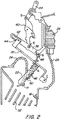
- FIG 2 is a partially cross-sectional side view of portions of the circuit breaker of FIG. 1 shown with its contacts in an open, tripped state.
- FIG 3 is a partially cross-sectional side view of a circuit breaker according to an exemplary embodiment of the present invention that operates in very similar fashion as does the circuit breaker of FIG 1 , but which is particularly designed for use in a front mount panel, as opposed to a DIN-rail mount panel, shown with its contacts in a closed, non-tripped state.
- the exemplary embodiments of the present invention are related to circuit interrupting devices capable of opening an electrical circuit rapidly and forcefully in the event of a fault or overcurrent condition or in the case that an actuation "off' is commanded.
- the interrupting devices of the exemplary embodiments are also capable of closing an electrical circuit rapidly in the event of resetting a tripped breaker or in the case that a manual actuation "on" is desired.
- the magnitude and/or duration of any arcs created between the opening and/or closing contacts can be kept relatively low, and good physical and electrical contact can be ensured when the contacts are closed.
- FIGS. 1 and 2 specifically relate to a circuit breaker (10) having a configuration particularly adapted for use in a DIN-rail mount panel
- FIG. 3 relates to a circuit breaker (10') particularly designed for use in a front mount panel. While the specific details of some elements of the circuit breakers (10,10') may differ from each other to accommodate differences in the two types of panels in which they are adapted to be mounted (as explained more fully below), the two exemplary embodiments are configured and operate in very similar fashion with respect to the basic functionality thereof.
- FIG. 1 the exemplary circuit breaker (10) according to one embodiment of the present invention, particularly configured for use in a DIN-rail mount panel, is shown in the closed position.
- the circuit breaker (10) can be used in any commercial or non-commercial application, and may be designed to replace current circuit breakers without the need to modify existing equipment.
- the circuit breaker (10) is designed to trip/open and/or reset/close more quickly and forcefully than traditional circuit breakers, and is therefore better adapted to protect a circuit and equipment connected thereto than traditional circuit breakers in various applications.
- the first terminal (12) which may be referred to as the line terminal (connected to the source of electrical power), is electrically connected to a first contact (16).
- the first contact (16) remains stationary and may be attached to the housing (20) of the circuit breaker (10).
- a second terminal (14) may be electrically connected to a load that receives the electrical power passing through the circuit breaker (10), and may therefore be referred to as a load terminal.
- a second contact (18) which is electrically connected to the second terminal (14), is in electrical communication with the first contact (16).
- the second contact (18) is movable relative to first contact (16), however, one of skill in the art would understand that either the first contact (16) or the second contact (18) or both could be moveable with respect to the other.
- the first contact (16) and the second contact (18) physically contact each other to create a closed circuit between the line (power) and the load (equipment receiving the power) so that electrical current flows between the terminals (12,14).
- the circuit breaker (10) is designed to automatically trip, causing the second contact (18) to separate from the first contact (16) thereby opening the electrical circuit.
- the moveable contact (18) is mounted toward one end of a moveable contact arm (22), which is pivotably connected, toward the opposite end, to be pivotable with respect to an axis (A).
- the moveable contact arm (22) is connected such that the moveable contact (18) is pivotable into and out of physical contact with stationary contact (16) by pivoting of the moveable contact arm (22) about the axis (A).
- the moveable contact (18) is in electrical communication with the load terminal (14) via a conductor (24) connected therebetween.
- the stationary contact (16) is in electrical communication, via a conductor (26), with an overcurrent mechanism (28), which in turn is in electrical communication, via a conductor (30), with the line terminal (12).
- the contacts (16,18) are in the closed state (shown in FIG. 1 )
- the contacts (16,18) are in the open state (shown in FIG. 2 )
- the line terminal (12) and the load terminal (14) are electrically isolated from one another.
- the overcurrent sensor (28) may take any of various forms, although in the embodiment shown, it takes the form of a hydraulic-magnetic overcurrent sensor (28) having an armature (32). Upon sensing an overcurrent or other type of fault situation, the armature (32) of the overcurrent sensor (28) acts upon a linkage assembly (described more fully below) to trip the circuit breaker (10), thereby causing the moveable contact arm (22) to pivot the moveable contact (18) out of physical contact with the stationary contact (16).
- a linkage assembly described more fully below
- a handle (34) is pivotably connected to the housing (20) such that a portion thereof extends from the housing (20) for manipulation by an operator and/or by a solenoid (as is known in the art).
- the handle (34) also cooperates, as do the previously mentioned armature (32) and the moveable contact arm (22), with the previously mentioned linkage mechanism, in order to provide automatic tripping of the breaker in overcurrent or other fault situations, resetting of a tripped breaker, and commanded on/off operation.
- this mechanism operably connected between the handle (34), the armature (32) of the overcurrent sensor (28) and the moveable contact arm (22), this mechanism generally comprises a first linkage (36), a second linkage (38) and a third linkage, which is generally referred to in the art as an escapement mechanism (40).
- a first end of the first linkage (36) is pivotably connected with respect to the housing (20) at an axis (B), with a second end thereof having an elongated channel (42) formed therein.
- the second linkage (38) has a first end that is pivotably connected with respect to said housing (20) at an axis (C), which is offset from axis (B) about which the first linkage (36) pivots.
- a second end of the second linkage (38) has a pin (44) disposed thereon, which pin (44) is slideably disposed within the elongated channel (42) formed in the first linkage (36).
- This pin/channel (44/42) arrangement allows the first linkage (36) and the second linkage (38) to interact with each other at the second end of each linkage, while also allowing them to simultaneously pivot about the two different axes (B,C).
- the axis (A) about which the moveable contact arm (22) pivots is disposed on the second linkage (38). This allows all three of the first linkage (36), the second linkage (38) and the moveable contact arm (22) to interact with each other in the snap-action fashion as described more fully below.
- the axis (A) about which the moveable contact arm (22) pivots is positioned on the second linkage (38) generally at a point disposed between the axis (C) about which the second linkage (38) pivots and the pin (44).
- the escapement mechanism (40) has a first end pivotably connected to the handle (34) at an axis point (D) and a second end pivotably connected to the first linkage (36) at an axis point (E).
- the armature (32) of the overcurrent sensor (28) cooperates with the escapement mechanism (40) to "pop" the escapement mechanism toward the left (with respect to the orientation shown in the Figures) in an overcurrent situation in order to cause the rest of the linkage mechanism to pivot the moveable contact arm (22) in a clockwise fashion (again with respect to the orientation shown in the Figures) to move the moveable contact (18) away from the stationary contact (16) to the open (i.e., "off') state shown in FIG. 2 .
- the escapement mechanism (40) causes the rest of the linkage mechanism to pivot the moveable contact arm (22) in a counterclockwise fashion (again with respect to the orientation shown in the Figures) to move the moveable contact (18) toward the stationary contact (16) to the closed (i.e., "on") state shown in FIG. 1 .
- the escapement "pops" back into the engaged position as shown in FIG. 1 to keep the contacts in the closed (i.e., "on") state.
- the moveable contact arm (22) defines a pivot angle with respect to the housing (20) as the moveable contact arm (22) pivots about the axis (A) and also as the second linkage (38), which carries the pivot axis (A), pivots about the axis (B).
- the moveable contact arm (22) defines a pivot angle of about 85 degrees clockwise from zero horizontal when in the closed (i.e., "on") state shown in FIG. 1
- the moveable contact arm (22) defines a pivot angle of about 145 degrees clockwise from the same zero horizontal when in the open (i.e., "off') state shown in FIG. 2 .
- a biasing member (46) exerts a biasing force on the moveable contact arm (22) which pivotally biases the moveable contact (18) toward the stationary contact (16) when the moveable contact (18) and said stationary contact (16) are in physical contact (i.e., are in the closed state), as shown in FIG. 1 .
- the biasing member (46) takes the form of a tension spring having a first end connected to a point fixed (48) with respect to the housing (20) and having a second end connected to the moveable contact arm (22) at a point (50) thereon. More specifically, in the embodiment shown in FIGS. 1 and 2 , the point (48) at which the tension spring is connected with respect to the housing (20) falls on axis (B) about which the first linkage (36) pivots, although such is not necessary.
- the biasing member (46), the linkages (36,38) and the moveable contact arm (22) are configured such that an angular position of the contact arm (22) is reached, after which the biasing member (46) begins biasing the moveable contact (18) away from the stationary contact (16) instead of toward it.
- this angle which may be referred to as the "zero-bias angle”
- there would be no bias in either rotational direction with all of the forces generated by the biasing member being generally parallel to the moveable contact arm (22), thereby resulting in compression forces felt by the moveable contact arm (22), and there being no forces tending to bias the moveable contact arm in either the clockwise or counterclockwise direction.
- This zero-bias angle may be reached when the pivot angle of the moveable contact arm (22) with respect to the housing (20) is such that the point (48) fixed with respect to the housing (20) at which the biasing member (46) is connected, the point (50) at which the biasing member (46) is connected to the moveable contact arm (22) and the axis (A) about which the moveable contact arm (22) pivots all lie in a common plane.
- This zero-bias angle will lie somewhere between the angle of the moveable contact arm (22) when the contacts (16,18) are in the closed (i.e., "on") state shown in FIG.
- the zero-bias angle may occur at about 115 degrees clockwise from the zero horizontal, although this angle may vary.
- the biasing of the moveable contact arm (22) provides for an increased rate at which the contacts are opened or closed, particularly at the time where the contacts are still relatively close to one another (i.e., just after opening or just prior to coming into contact during closing). This results in an arc with a reduced magnitude and/or duration than would be provided without the biasing. Nevertheless, arcing may not be completely prevented, such that an arc quenching assembly, for example, comprising a plurality of arc splitting plates (52), may be provided, as is known in the art.
- FIG. 3 the exemplary circuit breaker (10') according to another embodiment of the present invention, particularly configured for use in a front mount panel, is shown in the closed position.
- the circuit breaker (10') of this embodiment is very similar to the circuit breaker (10) described above in both structure and function, and therefore, a detailed description of this embodiment is not repeated.
Landscapes
- Breakers (AREA)
Applications Claiming Priority (1)
| Application Number | Priority Date | Filing Date | Title |
|---|---|---|---|
| US16/055,823 US10504668B1 (en) | 2018-08-06 | 2018-08-06 | Circuit breaker with snap action contacts |
Publications (2)
| Publication Number | Publication Date |
|---|---|
| EP3608933A1 true EP3608933A1 (de) | 2020-02-12 |
| EP3608933B1 EP3608933B1 (de) | 2022-01-19 |
Family
ID=64755286
Family Applications (1)
| Application Number | Title | Priority Date | Filing Date |
|---|---|---|---|
| EP18214873.4A Active EP3608933B1 (de) | 2018-08-06 | 2018-12-20 | Schutzschalter mit schnappkontakten |
Country Status (4)
| Country | Link |
|---|---|
| US (1) | US10504668B1 (de) |
| EP (1) | EP3608933B1 (de) |
| JP (1) | JP6783291B2 (de) |
| CN (1) | CN110808197B (de) |
Families Citing this family (1)
| Publication number | Priority date | Publication date | Assignee | Title |
|---|---|---|---|---|
| CN115346840A (zh) * | 2022-08-25 | 2022-11-15 | 德力西电气有限公司 | 手柄传动机构及插入式断路器 |
Citations (5)
| Publication number | Priority date | Publication date | Assignee | Title |
|---|---|---|---|---|
| CA1239959A (en) * | 1985-04-01 | 1988-08-02 | Harry A. Thompson | Circuit breaker mechanism |
| US5731561A (en) | 1993-09-24 | 1998-03-24 | Siemens Aktiengesellschaft | Power switch with an ARC quenching device |
| US6717090B2 (en) | 2001-11-16 | 2004-04-06 | Klaus Kling | Arc quenching configuration for an electrical switching device |
| EP2410548A1 (de) * | 2010-07-23 | 2012-01-25 | Eaton Industries GmbH | Schaltschloss für ein elektrisches Schaltgerät |
| EP3355334A1 (de) * | 2017-01-27 | 2018-08-01 | Carling Technologies Inc. | Hochspannungs-gleichstrom-relais |
Family Cites Families (4)
| Publication number | Priority date | Publication date | Assignee | Title |
|---|---|---|---|---|
| JP3166890B2 (ja) * | 1994-05-24 | 2001-05-14 | 富士電機株式会社 | 回路遮断器の消弧装置 |
| US6897747B2 (en) * | 2002-05-10 | 2005-05-24 | Joseph T. Brandon | Circuit breaker |
| CN101604601B (zh) * | 2009-06-05 | 2012-10-03 | 上海诺雅克电气有限公司 | 具有气压致动脱扣功能的快速跳闸断路器 |
| US9406470B2 (en) * | 2014-02-18 | 2016-08-02 | General Electric Company | Tri-stable flexure mechanism |
-
2018
- 2018-08-06 US US16/055,823 patent/US10504668B1/en active Active
- 2018-12-19 JP JP2018237405A patent/JP6783291B2/ja not_active Expired - Fee Related
- 2018-12-20 EP EP18214873.4A patent/EP3608933B1/de active Active
-
2019
- 2019-01-25 CN CN201910074045.6A patent/CN110808197B/zh not_active Expired - Fee Related
Patent Citations (5)
| Publication number | Priority date | Publication date | Assignee | Title |
|---|---|---|---|---|
| CA1239959A (en) * | 1985-04-01 | 1988-08-02 | Harry A. Thompson | Circuit breaker mechanism |
| US5731561A (en) | 1993-09-24 | 1998-03-24 | Siemens Aktiengesellschaft | Power switch with an ARC quenching device |
| US6717090B2 (en) | 2001-11-16 | 2004-04-06 | Klaus Kling | Arc quenching configuration for an electrical switching device |
| EP2410548A1 (de) * | 2010-07-23 | 2012-01-25 | Eaton Industries GmbH | Schaltschloss für ein elektrisches Schaltgerät |
| EP3355334A1 (de) * | 2017-01-27 | 2018-08-01 | Carling Technologies Inc. | Hochspannungs-gleichstrom-relais |
Also Published As
| Publication number | Publication date |
|---|---|
| US10504668B1 (en) | 2019-12-10 |
| CN110808197B (zh) | 2021-03-02 |
| EP3608933B1 (de) | 2022-01-19 |
| JP2020024897A (ja) | 2020-02-13 |
| CN110808197A (zh) | 2020-02-18 |
| JP6783291B2 (ja) | 2020-11-11 |
Similar Documents
| Publication | Publication Date | Title |
|---|---|---|
| US9679724B2 (en) | Component for electric power system, and contact assembly and open air arcing elimination method therefor | |
| EP2561534B1 (de) | Schutzschalter mit verbesserten lichtbogen-löschfähigkeiten | |
| RU2543997C2 (ru) | Расцепитель для электрического коммутационного устройства | |
| EP3343587B1 (de) | Leistungsschalter mit integriertem u-link | |
| KR20100033352A (ko) | 개선된 아크 퀀칭을 갖는 회로 차단기 | |
| CA2789187C (en) | Limiter including a number of gas channels and electrical switching apparatus employing the same | |
| EP3608933B1 (de) | Schutzschalter mit schnappkontakten | |
| US20210249208A1 (en) | Low-voltage circuit breaker | |
| US10510506B1 (en) | Narrow profile circuit breaker with arc interruption | |
| US9966209B1 (en) | Circuit breaker with arc shield | |
| US11764022B2 (en) | Slim circuit breaker | |
| Kay et al. | Safety through switching speed | |
| US10438754B2 (en) | Low profile circuit breaker with self cleaning contacts | |
| KR102003328B1 (ko) | 개선된 트립바 구조를 포함하는 소형 배선차단기 |
Legal Events
| Date | Code | Title | Description |
|---|---|---|---|
| PUAI | Public reference made under article 153(3) epc to a published international application that has entered the european phase |
Free format text: ORIGINAL CODE: 0009012 |
|
| STAA | Information on the status of an ep patent application or granted ep patent |
Free format text: STATUS: REQUEST FOR EXAMINATION WAS MADE |
|
| 17P | Request for examination filed |
Effective date: 20181220 |
|
| AK | Designated contracting states |
Kind code of ref document: A1 Designated state(s): AL AT BE BG CH CY CZ DE DK EE ES FI FR GB GR HR HU IE IS IT LI LT LU LV MC MK MT NL NO PL PT RO RS SE SI SK SM TR |
|
| AX | Request for extension of the european patent |
Extension state: BA ME |
|
| RBV | Designated contracting states (corrected) |
Designated state(s): AL AT BE BG CH CY CZ DE DK EE ES FI FR GB GR HR HU IE IS IT LI LT LU LV MC MK MT NL NO PL PT RO RS SE SI SK SM TR |
|
| RAP1 | Party data changed (applicant data changed or rights of an application transferred) |
Owner name: CARLING TECHNOLOGIES, INC. |
|
| GRAP | Despatch of communication of intention to grant a patent |
Free format text: ORIGINAL CODE: EPIDOSNIGR1 |
|
| STAA | Information on the status of an ep patent application or granted ep patent |
Free format text: STATUS: GRANT OF PATENT IS INTENDED |
|
| INTG | Intention to grant announced |
Effective date: 20211015 |
|
| RIC1 | Information provided on ipc code assigned before grant |
Ipc: H01H 71/50 20060101ALI20211004BHEP Ipc: H01H 5/08 20060101AFI20211004BHEP |
|
| GRAS | Grant fee paid |
Free format text: ORIGINAL CODE: EPIDOSNIGR3 |
|
| GRAA | (expected) grant |
Free format text: ORIGINAL CODE: 0009210 |
|
| STAA | Information on the status of an ep patent application or granted ep patent |
Free format text: STATUS: THE PATENT HAS BEEN GRANTED |
|
| AK | Designated contracting states |
Kind code of ref document: B1 Designated state(s): AL AT BE BG CH CY CZ DE DK EE ES FI FR GB GR HR HU IE IS IT LI LT LU LV MC MK MT NL NO PL PT RO RS SE SI SK SM TR |
|
| REG | Reference to a national code |
Ref country code: GB Ref legal event code: FG4D |
|
| REG | Reference to a national code |
Ref country code: CH Ref legal event code: EP |
|
| REG | Reference to a national code |
Ref country code: DE Ref legal event code: R096 Ref document number: 602018029734 Country of ref document: DE |
|
| REG | Reference to a national code |
Ref country code: AT Ref legal event code: REF Ref document number: 1464277 Country of ref document: AT Kind code of ref document: T Effective date: 20220215 |
|
| REG | Reference to a national code |
Ref country code: IE Ref legal event code: FG4D |
|
| REG | Reference to a national code |
Ref country code: LT Ref legal event code: MG9D |
|
| REG | Reference to a national code |
Ref country code: NL Ref legal event code: MP Effective date: 20220119 |
|
| REG | Reference to a national code |
Ref country code: AT Ref legal event code: MK05 Ref document number: 1464277 Country of ref document: AT Kind code of ref document: T Effective date: 20220119 |
|
| PG25 | Lapsed in a contracting state [announced via postgrant information from national office to epo] |
Ref country code: NL Free format text: LAPSE BECAUSE OF FAILURE TO SUBMIT A TRANSLATION OF THE DESCRIPTION OR TO PAY THE FEE WITHIN THE PRESCRIBED TIME-LIMIT Effective date: 20220119 |
|
| PG25 | Lapsed in a contracting state [announced via postgrant information from national office to epo] |
Ref country code: SE Free format text: LAPSE BECAUSE OF FAILURE TO SUBMIT A TRANSLATION OF THE DESCRIPTION OR TO PAY THE FEE WITHIN THE PRESCRIBED TIME-LIMIT Effective date: 20220119 Ref country code: RS Free format text: LAPSE BECAUSE OF FAILURE TO SUBMIT A TRANSLATION OF THE DESCRIPTION OR TO PAY THE FEE WITHIN THE PRESCRIBED TIME-LIMIT Effective date: 20220119 Ref country code: PT Free format text: LAPSE BECAUSE OF FAILURE TO SUBMIT A TRANSLATION OF THE DESCRIPTION OR TO PAY THE FEE WITHIN THE PRESCRIBED TIME-LIMIT Effective date: 20220519 Ref country code: NO Free format text: LAPSE BECAUSE OF FAILURE TO SUBMIT A TRANSLATION OF THE DESCRIPTION OR TO PAY THE FEE WITHIN THE PRESCRIBED TIME-LIMIT Effective date: 20220419 Ref country code: LT Free format text: LAPSE BECAUSE OF FAILURE TO SUBMIT A TRANSLATION OF THE DESCRIPTION OR TO PAY THE FEE WITHIN THE PRESCRIBED TIME-LIMIT Effective date: 20220119 Ref country code: HR Free format text: LAPSE BECAUSE OF FAILURE TO SUBMIT A TRANSLATION OF THE DESCRIPTION OR TO PAY THE FEE WITHIN THE PRESCRIBED TIME-LIMIT Effective date: 20220119 Ref country code: ES Free format text: LAPSE BECAUSE OF FAILURE TO SUBMIT A TRANSLATION OF THE DESCRIPTION OR TO PAY THE FEE WITHIN THE PRESCRIBED TIME-LIMIT Effective date: 20220119 Ref country code: BG Free format text: LAPSE BECAUSE OF FAILURE TO SUBMIT A TRANSLATION OF THE DESCRIPTION OR TO PAY THE FEE WITHIN THE PRESCRIBED TIME-LIMIT Effective date: 20220419 |
|
| PG25 | Lapsed in a contracting state [announced via postgrant information from national office to epo] |
Ref country code: PL Free format text: LAPSE BECAUSE OF FAILURE TO SUBMIT A TRANSLATION OF THE DESCRIPTION OR TO PAY THE FEE WITHIN THE PRESCRIBED TIME-LIMIT Effective date: 20220119 Ref country code: LV Free format text: LAPSE BECAUSE OF FAILURE TO SUBMIT A TRANSLATION OF THE DESCRIPTION OR TO PAY THE FEE WITHIN THE PRESCRIBED TIME-LIMIT Effective date: 20220119 Ref country code: GR Free format text: LAPSE BECAUSE OF FAILURE TO SUBMIT A TRANSLATION OF THE DESCRIPTION OR TO PAY THE FEE WITHIN THE PRESCRIBED TIME-LIMIT Effective date: 20220420 Ref country code: FI Free format text: LAPSE BECAUSE OF FAILURE TO SUBMIT A TRANSLATION OF THE DESCRIPTION OR TO PAY THE FEE WITHIN THE PRESCRIBED TIME-LIMIT Effective date: 20220119 Ref country code: AT Free format text: LAPSE BECAUSE OF FAILURE TO SUBMIT A TRANSLATION OF THE DESCRIPTION OR TO PAY THE FEE WITHIN THE PRESCRIBED TIME-LIMIT Effective date: 20220119 |
|
| PG25 | Lapsed in a contracting state [announced via postgrant information from national office to epo] |
Ref country code: IS Free format text: LAPSE BECAUSE OF FAILURE TO SUBMIT A TRANSLATION OF THE DESCRIPTION OR TO PAY THE FEE WITHIN THE PRESCRIBED TIME-LIMIT Effective date: 20220519 |
|
| REG | Reference to a national code |
Ref country code: DE Ref legal event code: R097 Ref document number: 602018029734 Country of ref document: DE |
|
| PG25 | Lapsed in a contracting state [announced via postgrant information from national office to epo] |
Ref country code: SM Free format text: LAPSE BECAUSE OF FAILURE TO SUBMIT A TRANSLATION OF THE DESCRIPTION OR TO PAY THE FEE WITHIN THE PRESCRIBED TIME-LIMIT Effective date: 20220119 Ref country code: SK Free format text: LAPSE BECAUSE OF FAILURE TO SUBMIT A TRANSLATION OF THE DESCRIPTION OR TO PAY THE FEE WITHIN THE PRESCRIBED TIME-LIMIT Effective date: 20220119 Ref country code: RO Free format text: LAPSE BECAUSE OF FAILURE TO SUBMIT A TRANSLATION OF THE DESCRIPTION OR TO PAY THE FEE WITHIN THE PRESCRIBED TIME-LIMIT Effective date: 20220119 Ref country code: EE Free format text: LAPSE BECAUSE OF FAILURE TO SUBMIT A TRANSLATION OF THE DESCRIPTION OR TO PAY THE FEE WITHIN THE PRESCRIBED TIME-LIMIT Effective date: 20220119 Ref country code: DK Free format text: LAPSE BECAUSE OF FAILURE TO SUBMIT A TRANSLATION OF THE DESCRIPTION OR TO PAY THE FEE WITHIN THE PRESCRIBED TIME-LIMIT Effective date: 20220119 Ref country code: CZ Free format text: LAPSE BECAUSE OF FAILURE TO SUBMIT A TRANSLATION OF THE DESCRIPTION OR TO PAY THE FEE WITHIN THE PRESCRIBED TIME-LIMIT Effective date: 20220119 |
|
| PLBE | No opposition filed within time limit |
Free format text: ORIGINAL CODE: 0009261 |
|
| STAA | Information on the status of an ep patent application or granted ep patent |
Free format text: STATUS: NO OPPOSITION FILED WITHIN TIME LIMIT |
|
| PG25 | Lapsed in a contracting state [announced via postgrant information from national office to epo] |
Ref country code: AL Free format text: LAPSE BECAUSE OF FAILURE TO SUBMIT A TRANSLATION OF THE DESCRIPTION OR TO PAY THE FEE WITHIN THE PRESCRIBED TIME-LIMIT Effective date: 20220119 |
|
| 26N | No opposition filed |
Effective date: 20221020 |
|
| PG25 | Lapsed in a contracting state [announced via postgrant information from national office to epo] |
Ref country code: SI Free format text: LAPSE BECAUSE OF FAILURE TO SUBMIT A TRANSLATION OF THE DESCRIPTION OR TO PAY THE FEE WITHIN THE PRESCRIBED TIME-LIMIT Effective date: 20220119 |
|
| P01 | Opt-out of the competence of the unified patent court (upc) registered |
Effective date: 20230607 |
|
| PG25 | Lapsed in a contracting state [announced via postgrant information from national office to epo] |
Ref country code: IT Free format text: LAPSE BECAUSE OF FAILURE TO SUBMIT A TRANSLATION OF THE DESCRIPTION OR TO PAY THE FEE WITHIN THE PRESCRIBED TIME-LIMIT Effective date: 20220119 |
|
| REG | Reference to a national code |
Ref country code: CH Ref legal event code: PL |
|
| REG | Reference to a national code |
Ref country code: BE Ref legal event code: MM Effective date: 20221231 |
|
| PG25 | Lapsed in a contracting state [announced via postgrant information from national office to epo] |
Ref country code: LU Free format text: LAPSE BECAUSE OF NON-PAYMENT OF DUE FEES Effective date: 20221220 |
|
| PG25 | Lapsed in a contracting state [announced via postgrant information from national office to epo] |
Ref country code: LI Free format text: LAPSE BECAUSE OF NON-PAYMENT OF DUE FEES Effective date: 20221231 Ref country code: IE Free format text: LAPSE BECAUSE OF NON-PAYMENT OF DUE FEES Effective date: 20221220 Ref country code: CH Free format text: LAPSE BECAUSE OF NON-PAYMENT OF DUE FEES Effective date: 20221231 |
|
| PG25 | Lapsed in a contracting state [announced via postgrant information from national office to epo] |
Ref country code: BE Free format text: LAPSE BECAUSE OF NON-PAYMENT OF DUE FEES Effective date: 20221231 |
|
| PGFP | Annual fee paid to national office [announced via postgrant information from national office to epo] |
Ref country code: GB Payment date: 20231026 Year of fee payment: 6 |
|
| PGFP | Annual fee paid to national office [announced via postgrant information from national office to epo] |
Ref country code: DE Payment date: 20231024 Year of fee payment: 6 |
|
| PG25 | Lapsed in a contracting state [announced via postgrant information from national office to epo] |
Ref country code: HU Free format text: LAPSE BECAUSE OF FAILURE TO SUBMIT A TRANSLATION OF THE DESCRIPTION OR TO PAY THE FEE WITHIN THE PRESCRIBED TIME-LIMIT; INVALID AB INITIO Effective date: 20181220 |
|
| PG25 | Lapsed in a contracting state [announced via postgrant information from national office to epo] |
Ref country code: CY Free format text: LAPSE BECAUSE OF FAILURE TO SUBMIT A TRANSLATION OF THE DESCRIPTION OR TO PAY THE FEE WITHIN THE PRESCRIBED TIME-LIMIT Effective date: 20220119 |
|
| PG25 | Lapsed in a contracting state [announced via postgrant information from national office to epo] |
Ref country code: MK Free format text: LAPSE BECAUSE OF FAILURE TO SUBMIT A TRANSLATION OF THE DESCRIPTION OR TO PAY THE FEE WITHIN THE PRESCRIBED TIME-LIMIT Effective date: 20220119 |
|
| PG25 | Lapsed in a contracting state [announced via postgrant information from national office to epo] |
Ref country code: MC Free format text: LAPSE BECAUSE OF FAILURE TO SUBMIT A TRANSLATION OF THE DESCRIPTION OR TO PAY THE FEE WITHIN THE PRESCRIBED TIME-LIMIT Effective date: 20220119 |
|
| PG25 | Lapsed in a contracting state [announced via postgrant information from national office to epo] |
Ref country code: TR Free format text: LAPSE BECAUSE OF FAILURE TO SUBMIT A TRANSLATION OF THE DESCRIPTION OR TO PAY THE FEE WITHIN THE PRESCRIBED TIME-LIMIT Effective date: 20220119 Ref country code: MC Free format text: LAPSE BECAUSE OF FAILURE TO SUBMIT A TRANSLATION OF THE DESCRIPTION OR TO PAY THE FEE WITHIN THE PRESCRIBED TIME-LIMIT Effective date: 20220119 |
|
| PG25 | Lapsed in a contracting state [announced via postgrant information from national office to epo] |
Ref country code: MT Free format text: LAPSE BECAUSE OF FAILURE TO SUBMIT A TRANSLATION OF THE DESCRIPTION OR TO PAY THE FEE WITHIN THE PRESCRIBED TIME-LIMIT Effective date: 20220119 |
|
| REG | Reference to a national code |
Ref country code: DE Ref legal event code: R119 Ref document number: 602018029734 Country of ref document: DE |
|
| GBPC | Gb: european patent ceased through non-payment of renewal fee |
Effective date: 20241220 |
|
| PG25 | Lapsed in a contracting state [announced via postgrant information from national office to epo] |
Ref country code: DE Free format text: LAPSE BECAUSE OF NON-PAYMENT OF DUE FEES Effective date: 20250701 |
|
| PG25 | Lapsed in a contracting state [announced via postgrant information from national office to epo] |
Ref country code: GB Free format text: LAPSE BECAUSE OF NON-PAYMENT OF DUE FEES Effective date: 20241220 |
|
| PGFP | Annual fee paid to national office [announced via postgrant information from national office to epo] |
Ref country code: FR Payment date: 20251008 Year of fee payment: 8 |