EP3608873B1 - Dispositif de génération, et procédé de génération et programme de modèle tridimensionnel - Google Patents
Dispositif de génération, et procédé de génération et programme de modèle tridimensionnel Download PDFInfo
- Publication number
- EP3608873B1 EP3608873B1 EP18887303.8A EP18887303A EP3608873B1 EP 3608873 B1 EP3608873 B1 EP 3608873B1 EP 18887303 A EP18887303 A EP 18887303A EP 3608873 B1 EP3608873 B1 EP 3608873B1
- Authority
- EP
- European Patent Office
- Prior art keywords
- image
- foreground
- dimensional shape
- shape data
- data corresponding
- Prior art date
- Legal status (The legal status is an assumption and is not a legal conclusion. Google has not performed a legal analysis and makes no representation as to the accuracy of the status listed.)
- Active
Links
- 238000000034 method Methods 0.000 title claims description 31
- 238000004590 computer program Methods 0.000 claims 1
- 238000012545 processing Methods 0.000 description 63
- 238000010586 diagram Methods 0.000 description 44
- 230000007547 defect Effects 0.000 description 30
- 238000000926 separation method Methods 0.000 description 22
- 230000006870 function Effects 0.000 description 18
- 230000000007 visual effect Effects 0.000 description 14
- 238000009877 rendering Methods 0.000 description 11
- 238000006243 chemical reaction Methods 0.000 description 9
- 230000010354 integration Effects 0.000 description 6
- 239000000284 extract Substances 0.000 description 3
- 230000015572 biosynthetic process Effects 0.000 description 2
- 238000007796 conventional method Methods 0.000 description 2
- 238000013461 design Methods 0.000 description 2
- 238000000605 extraction Methods 0.000 description 2
- 230000010365 information processing Effects 0.000 description 2
- 238000009434 installation Methods 0.000 description 2
- 239000011159 matrix material Substances 0.000 description 2
- NRNCYVBFPDDJNE-UHFFFAOYSA-N pemoline Chemical compound O1C(N)=NC(=O)C1C1=CC=CC=C1 NRNCYVBFPDDJNE-UHFFFAOYSA-N 0.000 description 2
- 235000004522 Pentaglottis sempervirens Nutrition 0.000 description 1
- 238000004040 coloring Methods 0.000 description 1
- 230000001419 dependent effect Effects 0.000 description 1
- 230000000694 effects Effects 0.000 description 1
- 238000003384 imaging method Methods 0.000 description 1
- 238000013507 mapping Methods 0.000 description 1
- 230000003287 optical effect Effects 0.000 description 1
- 238000005070 sampling Methods 0.000 description 1
- 238000013518 transcription Methods 0.000 description 1
- 230000035897 transcription Effects 0.000 description 1
- 238000013519 translation Methods 0.000 description 1
Images


Classifications
-
- G—PHYSICS
- G06—COMPUTING; CALCULATING OR COUNTING
- G06T—IMAGE DATA PROCESSING OR GENERATION, IN GENERAL
- G06T17/00—Three dimensional [3D] modelling, e.g. data description of 3D objects
-
- G—PHYSICS
- G06—COMPUTING; CALCULATING OR COUNTING
- G06T—IMAGE DATA PROCESSING OR GENERATION, IN GENERAL
- G06T1/00—General purpose image data processing
-
- G—PHYSICS
- G06—COMPUTING; CALCULATING OR COUNTING
- G06T—IMAGE DATA PROCESSING OR GENERATION, IN GENERAL
- G06T15/00—3D [Three Dimensional] image rendering
- G06T15/10—Geometric effects
- G06T15/20—Perspective computation
-
- G—PHYSICS
- G06—COMPUTING; CALCULATING OR COUNTING
- G06T—IMAGE DATA PROCESSING OR GENERATION, IN GENERAL
- G06T17/00—Three dimensional [3D] modelling, e.g. data description of 3D objects
- G06T17/10—Constructive solid geometry [CSG] using solid primitives, e.g. cylinders, cubes
-
- G—PHYSICS
- G06—COMPUTING; CALCULATING OR COUNTING
- G06T—IMAGE DATA PROCESSING OR GENERATION, IN GENERAL
- G06T19/00—Manipulating 3D models or images for computer graphics
-
- G—PHYSICS
- G06—COMPUTING; CALCULATING OR COUNTING
- G06T—IMAGE DATA PROCESSING OR GENERATION, IN GENERAL
- G06T5/00—Image enhancement or restoration
- G06T5/50—Image enhancement or restoration by the use of more than one image, e.g. averaging, subtraction
-
- G—PHYSICS
- G06—COMPUTING; CALCULATING OR COUNTING
- G06T—IMAGE DATA PROCESSING OR GENERATION, IN GENERAL
- G06T7/00—Image analysis
- G06T7/50—Depth or shape recovery
- G06T7/55—Depth or shape recovery from multiple images
-
- H—ELECTRICITY
- H04—ELECTRIC COMMUNICATION TECHNIQUE
- H04N—PICTORIAL COMMUNICATION, e.g. TELEVISION
- H04N23/00—Cameras or camera modules comprising electronic image sensors; Control thereof
- H04N23/60—Control of cameras or camera modules
-
- H—ELECTRICITY
- H04—ELECTRIC COMMUNICATION TECHNIQUE
- H04N—PICTORIAL COMMUNICATION, e.g. TELEVISION
- H04N23/00—Cameras or camera modules comprising electronic image sensors; Control thereof
- H04N23/90—Arrangement of cameras or camera modules, e.g. multiple cameras in TV studios or sports stadiums
-
- H—ELECTRICITY
- H04—ELECTRIC COMMUNICATION TECHNIQUE
- H04N—PICTORIAL COMMUNICATION, e.g. TELEVISION
- H04N7/00—Television systems
- H04N7/18—Closed-circuit television [CCTV] systems, i.e. systems in which the video signal is not broadcast
-
- G—PHYSICS
- G06—COMPUTING; CALCULATING OR COUNTING
- G06T—IMAGE DATA PROCESSING OR GENERATION, IN GENERAL
- G06T2207/00—Indexing scheme for image analysis or image enhancement
- G06T2207/10—Image acquisition modality
- G06T2207/10016—Video; Image sequence
-
- G—PHYSICS
- G06—COMPUTING; CALCULATING OR COUNTING
- G06T—IMAGE DATA PROCESSING OR GENERATION, IN GENERAL
- G06T2207/00—Indexing scheme for image analysis or image enhancement
- G06T2207/20—Special algorithmic details
- G06T2207/20212—Image combination
- G06T2207/20224—Image subtraction
-
- G—PHYSICS
- G06—COMPUTING; CALCULATING OR COUNTING
- G06T—IMAGE DATA PROCESSING OR GENERATION, IN GENERAL
- G06T2207/00—Indexing scheme for image analysis or image enhancement
- G06T2207/30—Subject of image; Context of image processing
- G06T2207/30196—Human being; Person
-
- G—PHYSICS
- G06—COMPUTING; CALCULATING OR COUNTING
- G06T—IMAGE DATA PROCESSING OR GENERATION, IN GENERAL
- G06T2207/00—Indexing scheme for image analysis or image enhancement
- G06T2207/30—Subject of image; Context of image processing
- G06T2207/30221—Sports video; Sports image
-
- G—PHYSICS
- G06—COMPUTING; CALCULATING OR COUNTING
- G06T—IMAGE DATA PROCESSING OR GENERATION, IN GENERAL
- G06T2207/00—Indexing scheme for image analysis or image enhancement
- G06T2207/30—Subject of image; Context of image processing
- G06T2207/30221—Sports video; Sports image
- G06T2207/30228—Playing field
Definitions
- the present invention relates to generation of a three-dimensional model of an object within an image.
- Document US 2009/141941 discloses a method for generating a three dimensional representation of a scene which includes a plurality of objects (players) disposed on a playing field.
- Publication " Multi-view Reconstruction of Unknown Objects within a Known Environment” to Stefan Kuhn et al. presents a general vision-based method for reconstructing multiple unknown objects (e.g. humans) within a known environment (e.g. tables, racks, robots) which usually has occlusions.
- FIG. 1A to FIG. 1C are diagrams showing the basic principles of the visual volume intersection method. From an image obtained by capturing a certain object, a mask image representing a two-dimensional silhouette of the object is obtained at the image sensing surface ( FIG. 1A ). Then, a pyramid form spreading into a three-dimensional space so that each side extends from the image capturing center of the camera and passes each point on the outline of the mask image is considered (FIG. IB). This pyramid form is called the target "visual volume” by the relevant camera. Further, by finding the common area of a plurality of visual volumes, that is, the intersection of the visual volumes, the three-dimensional shape (three-dimensional model) of an object is found ( FIG. 1C ).
- the three-dimensional shape of an object is estimated by projecting a sampling point in a space having a possibility that an object exists onto the mask image and verifying whether the projected point is included in the mask image in common to a plurality of viewpoints.
- NPL 1 Laurentini A "The Visual Hull Concept for Silhouette-Based Image Understanding", IEEE Transcriptions Pattern Analysis and machine Intelligence, Vol. 16, No. 2, pp. 150 - 162, Feb, 1994
- the mask image it is necessary for the mask image to be capable of correctly representing the silhouette of a target object and in a case where the silhouette on the mask image is incorrect, the three-dimensional shape that is generated is also incorrect.
- a part of a person, who is a target object is prevented from being captured by a stationary object, such as a structure, which exists in front of the person, and therefore, a part of the silhouette of the person represented by the mask image is lost, a defect occurs in the three-dimensional model that is generated.
- a mask image whose part of the silhouette is lost is not used, the geometric accuracy of the three-dimensional model that is obtained is reduced.
- the present invention has been made in view of the above-described problems and an object thereof is to prevent a defect from occurring in a three-dimensional model that is generated even in a case where a structure or the like that prevents a part of a target object from being captured exists within an image capturing scene.
- a generation device and method according to the present invention is defined by the appended independent and dependent claims.
- the present invention it is made possible to generate a three-dimensional model with high quality in which there is no defect or the degree of defect is reduced even in a case where a structure or the like that prevents a part of a target object from being captured exists within an image capturing scene.
- a three-dimensional model in which there is no defect or the degree of defect is reduced is generated for a foreground by using, in addition to a two-dimensional silhouette of the foreground in an image capturing scene, a mask image including a two-dimensional silhouette of a structure that prevents at least a part thereof from being captured.
- a three-dimensional model including a structure or the like that prevents a part of the foreground from being captured is generated.
- the "foreground” refers to a moving object existing within a captured image, which moves in a case where image capturing is performed in a time series from the same angle (whose absolute position may change) and which can be seen from a virtual viewpoint.
- the "structure” refers to a stationary object existing within a captured image, which does not move in a case where image capturing is performed in a time series from the same angle (whose absolute position does not change, that is, at rest) and which has a possibility of preventing the foreground from being captured.
- the three-dimensional model referred to here is data representing a three-dimensional shape.
- a case is supposed where a part of a foreground (moving object), such as a player and a ball, is prevented from being captured by a structure (stationary object), such as a soccer goal, at the time of generating a virtual viewpoint image by taking a soccer game as an image capturing scene.
- the virtual viewpoint image is a video image that is generated by an end user and/or an appointed operator and the like freely operating the position and orientation of a virtual camera and also called a free-viewpoint image, an arbitrary viewpoint image, and the like.
- the virtual viewpoint image that is generated and the multi-viewpoint image that is the source of the virtual viewpoint image may be a moving image or a still image.
- a case is explained as an example where a three-dimensional model for generating a virtual viewpoint image of a moving image is generated by using the multi-viewpoint image of the moving image.
- FIG. 2A is a block diagram showing an example of a configuration of a virtual viewpoint image generation system including a three-dimensional model generation device according to the present embodiment.
- a virtual viewpoint image generation system 100 includes a camera array 110 including a plurality of cameras, a control device 120, a foreground separation device 130, a three-dimensional model generation device 140, and a rendering device 150.
- the control device 120, the foreground separation device 130, the three-dimensional model generation device 140, and the rendering device 150 are each implemented by a CPU that performs calculation processing or a general computer (information processing apparatus) including a memory or the like storing results of calculation processing, programs, and the like.
- FIG. 2B is a diagram showing arrangement of a total of eight cameras 211 to 218 configuring the camera array 110 in a bird's eye diagram in a case where a field 200 is viewed from directly above.
- Each of the cameras 211 to 218 is installed at a predetermined height from the ground so as to surround the field 200 and acquires multi-viewpoint image data from different viewpoints by capturing the position in front of one of the goals from a variety of angles.
- a soccer court 210 is drawn (in fact, by white lines) and on the left side thereof, a soccer goal 202 is placed.
- a ⁇ mark 203 in front of the soccer goal 202 indicates a common line-of-sight direction (gaze point) of the cameras 211 to 218 and a broken line circle 204 indicates an area that each of the cameras 211 to 218 can perform image capturing with the gaze point 203 as a center.
- a position is represented in a coordinate system in which one corner of the filed 200 is taken as the origin, the long side direction as an x-axis, the short side direction as a y-axis, and the height direction as a z-axis.
- the data of the multi-viewpoint image obtained by each camera of the camera array 110 is sent to the control device 120 and the foreground separation device 130.
- each of the cameras 211 to 218, the control device 120, and the foreground separation device 130 are connected by a star topology, but the ring topology by the daisy chain connection or the bus topology may also be adopted.
- FIG. 2B the example in which the number of cameras is eight is described, but the number of cameras may be less than eight or exceed eight.
- the control device 120 generates camera parameters and a structure mask and supplies them to the three-dimensional model generation device 140.
- the camera parameters include external parameters representing the position and orientation (line-of-sight direction) of each camera and internal parameters representing the focal length and viewing angle (image capturing area) of a lens included in each camera and are obtained by calibration.
- the calibration is processing to find a correspondence relationship between a point in the three-dimensional world coordinate system obtained by using a plurality of images in which a specific pattern, such as a checker board, is captured, and a two-dimensional point corresponding thereto.
- the structure mask is a mask image representing a two-dimensional silhouette of the structure existing in each captured image acquired by each of the cameras 211 to 218.
- the mask image is a reference image that specifies which is the extraction-target portion within the captured image and a binary image represented by 0 and 1.
- the soccer goal 202 is handled as a structure and the silhouette image indicating the area of the soccer goal 202 (two-dimensional silhouette) within the image captured by each camera from a predetermined position and at a predetermined angle is the structure mask.
- the captured image that is the source of the structure mask it may be possible to use one captured at timing at which a player or the like, which is a foreground, does not exist, such as timing before or after the game or timing during the halftime.
- an image captured beforehand or afterward is not appropriate because image capturing is affected by the sunlight variation, for example, outdoors.
- the captured image that is the source of the structure mask by eliminating players or the like from a predetermined number of frames (for example, successive frames corresponding to ten seconds) of the moving image in which the players or the like are captured.
- a predetermined number of frames for example, successive frames corresponding to ten seconds
- the structure mask based on the image that adopts the median of each pixel value in each frame.
- the foreground separation device 130 performs processing to determine the foreground corresponding to the players and the ball on the field 200 as distinct from the background area except for the foreground area for each of the captured images from a plurality of viewpoints, which are input.
- a background image prepared in advance may be the same captured image that is the source of the structure mask
- a difference from the background image is found for each captured image and the area corresponding to the difference is specified as the foreground area. Due to this, the foreground mask indicating the foreground area for each captured image is generated.
- a binary image representing the pixel belonging to the foreground area representing the players and the ball by "0" and the pixel belonging to the background area except for the foreground by "1" is generated as the foreground mask.
- the three-dimensional model generation device 140 generates a three-dimensional model of an object based on the camera parameters and the multi-viewpoint image. Details of the three-dimensional model generation device 140 will be described later.
- the data of the generated three-dimensional model is output to the rendering device 150.
- the rendering device 150 generates a virtual viewpoint image based on the three-dimensional model received from the three-dimensional model generation device 140, the camera parameters received from the control device 120, the foreground image received from the foreground separation device 130, and the background image prepared in advance. Specifically, a position relationship between the foreground image and the three-dimensional model is found from the camera parameters and by mapping the foreground image corresponding to the three-dimensional model, a virtual viewpoint image in a case where an object of interest is viewed from an arbitrary angle is generated. In this manner, for example, it is possible to obtain a virtual viewpoint image of a decisive scene in front of the goal where a player has scored a point.
- the configuration of the virtual viewpoint image generation system shown in FIG. 2A is an example and the configuration is not limited to this.
- one computer may include the functions of a plurality of devices (for example, the foreground separation device 130, the three-dimensional model generation device 140, and the like).
- the module of each camera is caused to have the function of the foreground separation device 130 and from each camera, the captured image and the data of the foreground mask thereof are supplied.
- FIG. 3 is a function block diagram showing the internal configuration of the three-dimensional model generation device 140 according to the present embodiment.
- the three-dimensional model generation device 140 includes a data reception unit 310, a structure mask storing unit 320, a mask combination unit 330, a coordinate conversion unit 340, a three-dimensional model generation unit 350, and a data output unit 360. In the following, each unit is explained in detail.
- the data reception unit 310 receives the camera parameters of each camera configuring the camera array 110 and the structure mask representing the two-dimensional silhouette of the structure existing within the image capturing scene from the control device 120. Further, the data reception unit 310 receives the captured image (multi-viewpoint image) obtained by each camera of the cameral array 110 and the data of the foreground mask representing the two-dimensional silhouette of the foreground existing within each captured image from the foreground separation device 130.
- the structure mask is delivered to the structure mask storing unit 320, the foreground mask to the mask combination unit 330, the multi-viewpoint image to the coordinate conversion unit 340, and the camera parameters to the coordinate conversion unit 340 and the three-dimensional model generation unit 350, respectively.
- the structure mask storing unit 320 stores the structure mask in the RAM or the like and supplies the structure mask to the mask combination unit 330 as needed.
- the mask combination unit 330 reads the structure mask from the structure mask storing unit 320 and combines this with the foreground mask received from the data reception unit 310, and thus generates a mask image integrating both masks into one mask (hereinafter, called an "integrated mask").
- the generated integrated mask is sent to the three-dimensional model generation unit 350.
- the coordinate conversion unit 340 converts the multi-viewpoint image received from the data reception unit 310 from the camera coordinate system into the world coordinate system based on the camera parameters. By this coordinate conversion, each captured image whose viewpoint is different from one another is converted into information representing which area each captured image indicates on the three-dimensional space.
- the three-dimensional model generation unit 350 generates a three-dimensional model of an object including a structure within an image capturing scene by the visual volume intersection method by using the multi-viewpoint image converted into the world coordinate system and the integrated mask corresponding to each camera.
- the data of the generated three-dimensional model of the object is output to the rendering device 150 via the data output unit 360.
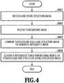
- FIG. 4 is a flowchart showing a flow of three-dimensional model forming processing according to the present embodiment. This series of processing is implemented by a CPU included in the three-dimensional model generation device 140 loading a predetermined program stored in a storage medium, such as a ROM and an HDD, onto a RAM and executing the program. In the following, explanation is given along the flow in FIG. 4 .
- the data reception unit 310 receives the structure mask representing the two-dimensional silhouette of the structure (here, the soccer goal 202) in a case where the structure is viewed from each of the cameras 211 to 218 and the camera parameters of each camera from the control device 120.
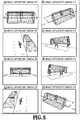
- FIG. 5A to FIG. 5H each show an image captured by each of the cameras 211 to 218 configuring the camera array 110.
- one player goal keeper
- the soccer goal 202 exists between the camera and the player, and therefore, a part of the player is hidden by the soccer goal 202. From each captured image in FIG.
- FIG. 6A to FIG. 6H each show the structure mask corresponding to each captured image in FIG. 5A to FIG. 5H .
- the data reception unit 310 receives the foreground mask indicating the two-dimensional silhouette of the foreground (here, players and ball) in the image captured by each of the cameras 211 to 218 from the foreground separation device 130 along with the multi-viewpoint image that is the source of the foreground mask.
- FIG. 7A to FIG. 7H each show the foreground mask corresponding to each captured image in FIG. 5A to FIG. 5H .
- the foreground separation device 130 extracts the area that changes over time between the images captured from the same angle as the foreground, and therefore, in each of FIG. 7A, FIG. 7B, and FIG. 7H , the area of a part of the player hidden by the soccer goal 202 is not extracted as the foreground area.
- the data of the received foreground mask is sent to the mask combination unit 330.
- the mask combination unit 330 performs processing to read the data of the structure mask from the structure mask storing unit 320 and combine the read structure mask and the foreground mask received from the data reception unit 310.
- This combination is calculation processing to find logical OR for each pixel of the foreground mask and the structure mask, both represented by two values (white and black).
- FIG. 8A to FIG. 8H each show an integrated mask obtained by combining each structure mask shown in FIG. 6A to FIG. 6H and each foreground mask shown in FIG. 7A to FIG. 7H . In the completed integrated mask, no defect is seen in the silhouette of the player.
- the three-dimensional model generation unit 350 generates a three-dimensional model by using the visual volume intersection method based on the integrated mask obtained at step 403. Due to this, a model (hereinafter, called "integrated three-dimensional model") representing the three-dimensional shape of the foreground and the structure existing in the common image capturing area of a plurality of images captured from different viewpoints.
- the integrated three-dimensional model including the soccer goal 202, in addition to the player and the ball is generated.
- the generation of the integrated three-dimensional model is performed specifically by the procedure as follows. First, volume data in which the three-dimensional space on the field 200 is filled with cubes (voxels) having a predetermined size is prepared.
- the value of the voxel configuring the volume data is represented by 0 and 1 and " 1 " indicates an area contributing to shape formation and "0" indicates an area does not contributing to shape formation, respectively.
- the three-dimensional coordinates of the voxel are converted from the world coordinate system into the camera coordinate system by using the camera parameters (installation position, line-of-sight direction, and the like) of each of the cameras 211 to 218. Then, in a case where the structure and the foreground indicated by the integrated mask exist in the camera coordinate system, a model representing of the three-dimensional shape of the structure and the foreground by voxels is generated.
- FIG. 9 shows the integrated three-dimensional model that is generated based on the integrated mask shown in FIG. 8A to FIG. 8H and symbol 901 corresponds to the three-dimensional shape of the player, who is the foreground, and symbol 902 corresponds to the three-dimensional shape of the soccer goal 202, which is the structure.
- symbol 901 corresponds to the three-dimensional shape of the player, who is the foreground
- symbol 902 corresponds to the three-dimensional shape of the soccer goal 202, which is the structure.
- FIG. 10 shows a three-dimensional model that is generated using only the foreground mask by the conventional method.
- the foreground mask shown in FIG. 7A, FIG. 7B, and FIG. 7H a part of the player is not represented as the foreground area, and therefore, the part becomes a defect in the generated three-dimensional model.
- the method of the present embodiment by using the mask image combining the foreground mask and the structure mask, it is made possible to avoid a defect from occurring in a part of the three-dimensional model of the foreground.
- a three-dimensional model for each frame is generated by repeatedly performing the processing at each step described above in units of frames.
- image capturing is performed at the same image capturing location by changing the date, it may also be possible to perform reception and storing of the structure mask only at the first time and store it in the RAM or the like, and use the stored structure mask at the next and subsequent times.
- a three-dimensional model of a foreground with no defect or in which the degree of defect is reduced is generated, which includes a structure existing within an image capturing scene.
- a three-dimensional model with only the foreground, from which a structure is removed, and in which there is no defect or in which the degree of defect is reduced is generated.
- the configuration of the three-dimensional model generation device 140 of the present embodiment is also basically the same as that of the first embodiment (see FIG. 3 ), but different in the following points.
- reading of the structure mask for the structure mask storing unit 320 is performed not only by the mask combination unit 330 but also by the three-dimensional model generation unit 350.
- the broken-line arrow in FIG. 3 indicates this.
- generation of a three-dimensional model of only the structure using the structure mask is also performed.
- a three-dimensional model of only the foreground with no defect or in which the degree of defect is reduced is extracted.
- FIG. 11 is a flowchart showing a flow of three-dimensional model forming processing according to the present embodiment.
- the series of processing is implemented by a CPU included in the three-dimensional model generation device 140 loading a predetermined program stored in a storage medium, such as a ROM and an HDD, onto a RAM and executing the program.
- a storage medium such as a ROM and an HDD
- Step 1101 to step 1104 correspond to step 401 to step 404, respectively, in the flow in FIG. 4 of the first embodiment and there is no difference, and therefore, explanation is omitted.
- the three-dimensional model generation unit 350 reads the structure mask from the structure mask storing unit 320 and generates a three-dimensional model of the structure by the visual volume intersection method.
- the three-dimensional model generation unit 350 finds the difference between the combined three-dimensional model of the foreground and the structure generated at step 1104 and the three-dimensional model of the structure generated at step S1105 and extracts the three-dimensional model of only the foreground.
- the portion of the three-dimensional model of the foreground is prevented from being removed erroneously. It may also be possible to linearly change the expansion ratio at this time in accordance with the distance from the foreground or determine the expansion ratio stepwise by providing one or a plurality of distances as a reference.
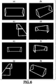
- FIG. 12A shows an integrated three-dimensional model generated based on the integrated mask, the same as that in FIG. 9 described previously.
- FIG. 12B shows a three-dimensional model of the structure generated based on only the structure mask.
- FIG. 12C shows a three-dimensional model of only the foreground obtained from the difference between the integrated three-dimensional model in FIG. 12A and the three-dimensional model of the structure in FIG. 12B .
- a three-dimensional model for each frame is generated by repeatedly performing the processing at each step described above in units of frames.
- the three-dimensional model of only the foreground is generated by subtracting the three-dimensional model of the structure from the integrated three-dimensional model of the foreground and the structure.
- the three-dimensional model of only the foreground is found by counting which mask image a voxel is included in for each voxel configuring the integrated three-dimensional model of the foreground and the structure (or for each predetermined area) and removing the portion whose count value is less than or equal to a threshold value from the integrated three-dimensional model.
- a first threshold value an arbitrary value smaller than the total number of cameras is set by taking into consideration the installation position, the line-of-sight direction, and the like of each camera. Then, a three-dimensional model of a target object including the partial area for which it is not determined that the condition is met.
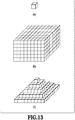
- FIG. 13A shows a single cubic voxel.
- FIG. 13B shows a set of voxels representing a three-dimensional model generation-target space.
- the voxel is a minute partial area configuring the three-dimensional space.
- FIG. 13C shows an example in which a set of voxels of a three-dimensional model of a quadrangular pyramid is generated by removing the voxels in the area other than the quadrangular pyramid area from the set in FIG. 13B , which is the set of voxels of the target space.
- the three-dimension space and the three-dimensional model are configured by cubic voxels, but this not limited and the three-dimension space and the three-dimensional model may be configured by a point cloud or the like.
- the block diagram showing the configuration example of the virtual viewpoint image generation system including the three-dimensional model generation device according to the present embodiment is the same as that shown in FIG. 2A , and therefore, explanation is omitted.
- the camera array 110 is an image capturing apparatus group including a plurality of cameras 110a to 110z and captures an object from a variety of angles and outputs images to the foreground separation device 130 and the control device 120. It is assumed that the camera 110a to the camera 110z, the foreground separation device 130, and the control device 120 are connected by a star topology, but may be connected by a topology of ring, bus, or the like by daisy chain connection.
- the camera array 110 is arranged on the periphery of the sports stadium, for example, as shown in FIG. 14 and performs image capturing in synchronization toward a gaze point on the field common to all the cameras from a variety of angles. However, it may also be possible to set a plurality of gaze points, such as a gaze point toward which half of the cameras included in the camera array 110 is caused to face and another gaze point toward which the rest of the cameras is caused to face.
- the foreground is a predetermined target object (object that is a target for which a three-dimensional model is generated based on captured images) that enables viewing from an arbitrary angle at a virtual viewpoint and in the present embodiment, refers to a person existing on the filed of the sports stadium.
- the background is the area except for the foreground and in the present embodiment, refers to the entire sports stadium (field, spectator stand, and the like).
- the foreground and the background are not limited to those examples.
- the virtual viewpoint image in the present embodiment includes all the images representing the appearance from the virtual viewpoint at which no camera is installed, not only the images representing the appearance from a viewpoint that can be specified freely.
- the control device 120 calculates camera parameters indicating the position and orientation of the camera 110a to the camera 110z from the images captured in synchronization by the camera array 110 and outputs the calculated camera parameters to the three-dimensional model generation device 140.
- the camera parameters include external parameters and internal parameters.
- the external parameters include a rotation matrix and a translation matrix and indicate the position and orientation of the camera.
- the internal parameters include information on the focal length, the optical center, and the like of the camera and indicate the viewing angle of the camera, the size of the imaging sensor, and the like.
- the processing to calculate the camera parameter is called calibration. It is possible to find the camera parameter by using a correspondence relationship between points in the three-dimensional world coordinate system acquired by using a plurality of images obtained by capturing a specific pattern, for example, such as a checkerboard, and two-dimensional points corresponding thereto.
- the control device 120 calculates a structure mask image indicating a structure area having a possibility of overlapping in front of the foreground in the images captured by the camera 110a to the camera 110z and outputs information on the calculated structure mask image.
- a structure is a stationary object installed within the image capturing-target space and as an example, the soccer goal is handed as a structure and the image indicating the area of the goal within the image captured by each camera is a structure mask image.
- the foreground separation device 130 identifies the area in which a person on the field exists as the foreground and the background area except for the foreground from the images captured by the plurality of cameras, which are input from the camera array 110, and outputs the foreground mask image indicating the foreground area.
- the method of identifying the foreground area it is possible to use a method of identifying an area in which there is a difference between the background image stored in advance and the captured image as the foreground image or a method of identifying an area of a moving object as the foreground area.
- the mask image is a reference image representing a specific portion desired to be extracted from a captured image and a binary image represented by 0 and 1.
- the foreground mask image indicates the area in which the foreground, for example, such as a player, exists in a captured image and an image in which the pixel indicating the foreground area is represented by 1 and the pixel other than the foreground by 0 at the same resolution as that of the captured area.
- the format of a mask image is not limited to this and may be any information indicating the area of a specific object within a captured image.
- the three-dimensional model generation device 140 has a function as an information processing apparatus that generates a three-dimensional model by using a plurality of captured images captured by the plurality of cameras. First, the three-dimensional model generation device 140 receives the camera parameters and the information on the structure mask image from the control device 120 and receives the foreground mask image from the foreground separation device 130. Then, the three-dimensional model generation device 140 generates an integrated mask image indicating an integrated area by integrating the structure mask image and the foreground mask image.
- the three-dimensional model generation device 140 determines whether or not to remove each voxel based on the number of cameras for which each voxel (in fact, a point corresponding to a voxel and this applies hereinafter) within the space that is the target of generation of the three-dimensional model of the foreground is not included in the integrated mask image and the number of cameras for which each voxel is included in the foreground mask image. Then, based on the remaining voxels after removal of voxels determined to be removed, the three-dimensional model of the foreground is generated by, for example, the visual volume intersection method and output to the rendering device 150.
- the rendering device 150 receives the three-dimensional model from the three-dimensional model generation device 140 and receives the image indicating the foreground from the foreground separation device 130. Further, the rendering device 150 performs coloring by finding the position relationship between the image indicating the foreground and the three-dimensional model from the camera parameters and pasting the foreground image corresponding to the three-dimensional model, and thus generates a virtual viewpoint image in a case where the three-dimensional model is observed from an arbitrary viewpoint. In the virtual viewpoint image, the image of the background may be included.
- the rendering device 150 may also be possible for the rendering device 150 to generate a virtual viewpoint image in a case where the background and the foreground are viewed from a set viewpoint by setting the model of the background, the model of the foreground, and the position of the viewpoint within the three-dimensional space.
- the three-dimensional model generation device 140 includes a reception unit 155, a structure mask storing unit 101, a camera parameter storing unit 102, a mask integration unit 103, a coordinate conversion unit 104, a mask inside/outside determination unit 105, a threshold value setting unit 106, a foreground model generation unit 107, and an output unit 108.
- the reception unit 155 receives the camera parameters of each camera configuring the camera array 110 and the structure mask image indicating the area of the structure from the control device 120. Further, the reception unit 155 receives the image captured by each camera of the camera array 110 and the foreground mask image indicating the foreground area within the image from the foreground separation device 130 each time of image capturing.
- the structure mask storing unit 101 stores the structure mask image received by the reception unit 155.
- the structure mask image is a fixed image in accordance with the position of the camera.
- the camera parameter storing unit 102 stores external parameters indicating the position and/or orientation of each camera, which are captured by the camera array 110, and internal parameters indicating the focal length and/or image size as camera parameters.
- the mask integration unit 103 generates an integrated mask image by integrating the foreground mask image received from the foreground separation device 130 each time image capturing is performed by the camera array 110 and the structure mask image stored in the structure mask storing unit 101. Details of the integration method of the foreground mask image and the structure mask image will be described later.
- the coordinate conversion unit 104 calculates the position and viewing angle of each captured image in the world coordinate system based on the camera parameters stored in the camera parameter storing unit 102 and converts them into information representing which captured area on the three-dimensional space each captured image indicates.
- the mask inside/outside determination unit 105 determines, in a case where the number of cameras for which each voxel within the target voxel space is included inside the foreground mask image is less than or equal to a threshold value, to remove the voxel. Further, the mask inside/outside determination unit 105 determines, in a case where the number of cameras for which each voxel within the target voxel space is not included inside the integrated mask image is more than or equal to another threshold value, to remove the voxel.
- the threshold value setting unit 106 sets each threshold value for determining whether or not to remove a voxel by the mask inside/outside determination unit 105. This threshold value may be set in accordance with a user operation for the three-dimensional model generation device 140 or may be set automatically by the threshold value setting unit 106.
- the foreground model generation unit 107 removes voxels determined to be removed by the mask inside/outside determination unit 105 of the voxels within the target voxel space and generates a three-dimensional model based on the remaining voxels.
- the output unit 108 outputs the three-dimensional model generated by the foreground model generation unit 107 to the rendering device 150.
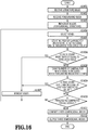
- FIG. 16 is a flowchart showing a procedure of processing performed by the three-dimensional model generation device according to the present embodiment.
- the reception unit 155 receives the structure mask image of each camera configuring the camera array 110 from the control device 120.
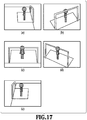
- FIG. 17A to FIG. 17E show examples of five captured images captured by the five cameras configuring a part of the camera array 110.
- one person exists on the field and the goal exists on the field as a structure
- the goal which is a structure, exists in front of the person, and therefore, a part of the person is hidden.
- FIG. 18A to FIG. 18E each show the structure mask image corresponding to each captured image shown in FIG. 17A to FIG. 17E .
- the structure mask image is shown as a binary image in which the area of the goal, which is a structure, is 1 (white) and the area except for the structure is 0 (black).
- the reception unit 155 receives the foreground mask image indicating the foreground area from the foreground separation device 130.
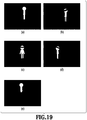
- FIG. 19A to FIG. 19E each show the foreground mask image corresponding to each captured image shown in FIG. 17A to FIG. 17E .
- the foreground separation device 130 extracts an area that changes over time as the foreground area, and therefore, the area of a part of the person, which is hidden by the goal, is not extracted as the foreground area as in FIG. 19B, FIG. 19C, and FIG. 19D . Further, in FIG. 19E , a part of the leg of the person, which does not change over time, is not extracted as the foreground area.
- the mask integration unit 103 generates an integrated mask image by integrating the structure mask image and the foreground mask image received at S1601 and S1602.
- FIG. 20A to FIG. 20E each show an example of the integrated mask image, which is the results of integrating the structure mask image shown in each of FIG. 18A to FIG. 18E and the foreground mask image shown in each of FIG. 19A to FIG. 19E .
- the integrated mask image is calculated by OR (logical sum) of the foreground mask image and the structure mask image, both represented by two values.
- the mask inside/outside determination unit 105 selects one voxel that is not selected yet from the target voxel space.
- the mask inside/outside determination unit 105 counts the number of cameras for which the selected one voxel is not included inside the mask area of the integrated mask image of each camera (hereinafter, called False Count).
- the mask inside/outside determination unit 105 determines whether or not False Count is more than or equal to a threshold value. In a case where False Count is more than or equal to the threshold value, it is possible to determine that the selected one voxel is neither foreground nor structure, and therefore, the processing advances to S1607, Due to this, it is possible to remove many voxels, which are obviously a non-foreground. On the other hand, in a case where False Count is less than the threshold value, it is possible to determine that the selected one voxel is a foreground or a structure, and therefore, the processing advances to S1608.
- the foreground model generation unit 107 removes the selected one voxel from the target voxel space.
- the mask inside/outside determination unit 105 counts the number of cameras for which the selected one voxel is included inside the mask area of the foreground mask image of each camera (hereinafter, called True Count).
- the mask inside/outside determination unit 105 determines whether or not True Count is less than or equal to another threshold value. In a case where True Count is less than or equal to another threshold value, it is possible to determine that the selected one voxel is a structure, and therefore, the processing advances to S1607 and the selected one pixel is removed from the target voxel space. On the other hand, in a case where True Count exceeds another threshold value, it is possible to determine that the selected one voxel is a foreground, and therefore, the selected one voxel is not removed from the target voxel space.
- the mask inside/outside determination unit 105 determines whether not the processing has been completed for all the voxels within the target voxel space. In a case where the processing has been completed for all the voxels, the processing advances to S1611. On the other hand, in a case where the processing has not been completed for all the voxels, the processing returns to S1604, and the next one voxel is selected from among voxels not selected yet and the same processing is performed afterward.
- the foreground model generation unit 107 generates a three-dimensional model of the foreground by using the remaining voxels after removal determination of voxels is performed for the target voxel space.
- the output unit 108 outputs the three-dimensional model of the foreground generated by the foreground model generation unit 107 to the rendering device 150.
- the above series of processing is performed for each frame captured by each camera.
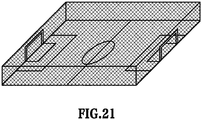
- FIG. 21 is a diagram showing a voxel space, which is a three-dimensional model generation target, of the sports stadium system according to the present embodiment and the cuboid area indicated by grids represents the target voxel space.
- FIG. 22 shows an example of False Count / True Count and determination results of voxels for the person, the leg of the person, the head of the person, the goal, and the other area, respectively, as the foreground, the foreground not detected by a part of the cameras, the foreground hidden by the structure, the structure, and the non-foreground in a case where the sports stadium is captured by the 16 cameras shown in FIG. 14 .
- the goal which is a structure
- these are not extracted as the foreground by the foreground separation device 130.
- FIG. 23 is a diagram showing an example of a three-dimensional model generated by applying threshold-based determination of False Count.
- True Count of the voxel located in the area of the goal, which is a structure is 0 and less than or equal to the threshold value, and therefore, the voxel is removed.
- True Count of the voxels located in the areas of the person, the leg of the person, and the head are 16, 15, and 13, respectively, exceeding the second threshold value, and therefore, the voxels are not removed.
- FIG. 22 is a diagram showing an example of a three-dimensional model generated by applying the threshold-based determination of False Count and the threshold-based determination of True Count.
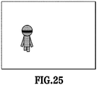
- FIG. 25 shows an example in which a three-dimensional model is generated by the visual volume intersection method using only the foreground mask image shown in FIG. 19A to FIG. 19E .
- FIG. 19A the entire person is captured, but in the captured images shown in FIG. 19B, FIG. 19C, and FIG. 19D , a part of the head of the person is hidden by the goad, which is a structure. Further, in the captured image shown in FIG. 19E , the leg of the person is not extracted as the foreground. Because of this, in the generated three-dimensional model also, a part becomes a defect.
- the voxel for each voxel within the space, which is the target for which a three-dimensional model of the target object (foreground) is generated, whether or not the number of cameras for which the target voxel is included in the foreground mask image indicating the area of the foreground is less than or equal to the threshold value (threshold value of True Count) is determined and in a case where the number is less than or equal to the threshold value, the voxel is removed.
- the threshold value threshold value of True Count
- the present embodiment even in a case where there is a defect in the foreground mask image indicating the area of the target object (foreground), it is possible to avoid a defect in a three-dimensional model to be generated of the target object (foreground) and improve quality of the three-dimensional model.
- an integrated mask image is generated by integrating the foreground mask image and the structure mask image and in a case where the number of cameras for which the target voxel is not included in the integrated mask image is more than or equal to the threshold value (False Count), it is determined to remove the voxel. Due to this, it is possible to remove many voxels, which are obviously a non-foreground, and therefore, it is made possible to improve the speed of the processing in the post stage.
- the threshold value False Count
- the three-dimensional model generation device 140 further includes an viewing angle inside/outside determination unit 109 and a threshold value calculation unit 260, in addition to the reception unit 155, the structure mask storing unit 101, the camera parameter storing unit 102, the mask integration unit 103, the coordinate conversion unit 104, the mask inside/outside determination unit 105, the threshold value setting unit 106, the foreground model generation unit 107, and the output unit 108.
- the basic configuration of the virtual viewpoint image generation system is the same as that of the first to third embodiments, and therefore, explanation is omitted.
- reception unit 155 the structure mask storing unit 101, the camera parameter storing unit 102, the mask integration unit 103, the coordinate conversion unit 104, the mask inside/outside determination unit 105, the threshold value setting unit 106, the foreground model generation unit 107, and the output unit 108 configuring the three-dimensional model generation device 140 are the same as those of the third embodiment, and therefore, explanation is omitted.
- the viewing angle inside/outside determination unit 109 determines whether or not each voxel within the target voxel space is within the image capturing range of each camera based on the camera parameters of each camera.
- the threshold value calculation unit 260 calculates a value obtained by multiplying the number of cameras for which it is determined that each voxel is within the image capturing range by a predetermined ratio as the threshold value of True Count. For example, in a case where the number of cameras for which a certain voxel is within the image capturing range is five and the predetermined ratio is 60%, the threshold value of True Count for the voxel is calculated as 3.
- the threshold value calculated by the threshold value calculation unit 260 is output to the threshold value setting unit 106 and the threshold value setting unit 106 sets the threshold value input from the threshold value calculation unit 260 as the threshold value of True Count.
- the threshold value is set to a predetermined value in a case where the number of such cameras is less than a predetermined number.
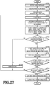
- FIG. 27 is a flowchart showing a procedure of processing performed by the three-dimensional model generation device according to the present embodiment.
- Each piece of processing at S2701 to S2704 is the same as each piece of processing at S1601 to S1604 in the flow in FIG. 16 of the third embodiment, and therefore, explanation is omitted.
- the viewing angle inside/outside determination unit 109 determines whether or not the one voxel selected at S2704 is included inside the viewing angle of each camera based on the camera parameters of each camera.
- the mask inside/outside determination unit 105 counts the number of cameras for which the selected one voxel is not included inside the mask area of the integrated mask image of each camera and for which the selected one voxel is included inside the viewing angle (hereinafter, called False Count).
- Each piece of processing at S2707 to S2709 is the same as each piece of processing at S1606 to S1608 in the flow in FIG. 16 described previously, and therefore, explanation is omitted.
- the threshold value calculation unit 260 calculates the threshold value of True Count based on the number of cameras for which the selected one voxel is included inside the viewing angle.
- the threshold value setting unit 106 sets the threshold value of True Count calculated by the threshold value calculation unit 260.
- Each piece of processing at S2711 to S2714 is the same as each piece of processing at S1609 to S1612 in the flow in FIG. 16 described previously, and therefore, explanation is omitted.
- the above is the series of processing in the flow in FIG. 27 .
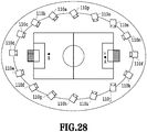
- FIG. 28 shows the way the sports stadium including a foreground A indicated by a black point at a position near to a gaze point indicated by the ⁇ mark in FIG. 28 and a foreground B indicated by a black point at a position far from the gaze point is captured by the 16 cameras as in FIG. 14 . It is assumed that the foreground A is inside the viewing angle of all the 16 cameras and the foreground B is inside the viewing angle of only the three cameras 110k, 1101, and 110m.
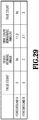
- FIG. 29 shows an example of False Count / True Count of each of the voxel at the position of the foreground A near from the gaze point and the voxel at the position of the foreground B far from the gaze point in the camera arrangement shown in FIG. 28 . It is assumed that the threshold value of False Count is a fixed value of 10 and the threshold value of True Count is 70% of the number of cameras for which the voxel is included inside viewing angle.
- the voxel located at the foreground A near to the gaze point is included within the integrated mask image of all the 16 cameras, and therefore, no camera exists for which the voxel is outside the integrated mask image. Consequently, the number of cameras for which the voxel is outside the integrated mask image and for which the voxel is inside the viewing angle is zero, and therefore, False Count is 0.
- the threshold value of True Count is 11.2, which is 70% of 16. Then, the voxel located at the foreground A near to the gaze point is within the foreground mask image of all the cameras, and True Count is 16 and the count value is more than or equal to the threshold value (11.2), and therefore, the voxel is not removed.
- the voxel at the position of the foreground B far from the gaze point is outside the viewing angle of the 13 cameras (13 cameras except for the cameras 110k, 1101, and 110m) and inside the viewing angle of the three cameras (the cameras 110k, 1101, and 110m). Further, the voxel is within the integrated mask image of the three cameras (camera 110k, 1101, and 110m). Consequently, the number of cameras for which the voxel is outside the integrated mask image and for which the voxel is inside the viewing angle is zero, and therefore, False Count is 0.
- the threshold value of True Count is 2.1, which is 70% of 3. Then, the voxel located at the foreground B far from the gaze point is within the foreground mask image of the three cameras, and True Count is 3 and the count value is more than or equal to the threshold value (2.1), and therefore, the voxel is not removed.
- the aspect is explained in which only the cameras for which the voxel is included within the foreground mask image is counted as True Count of each voxel.
- a voxel located at the position of a foreground that is hidden by a structure in many cameras may be removed because True Count does not exceed the threshold value. Consequently, an aspect is explained as a fifth embodiment in which a three-dimensional model without a defect is generated even in a case where a foreground is prevented from being captured by a structure in many cameras.
- the voxel even in a case where a target voxel is outside a foreground mask image, on a condition that the target voxel is included within a structure mask image, the voxel has a possibility of being a foreground, and therefore, a defect of the foreground is avoided by adding a value obtained by multiplying the number of cameras for which it is determined that the voxel is included within the structure mask image by a weight value to True Count.
- a weight value is set based on the number of cameras for which the target voxel is included in the structure mask image. Then, in a case where the sum of the number of cameras for which the target voxel is included in the foreground mask image and the value obtained by multiplying the number of cameras for which the target voxel is included in the structure mask image by the weight value is less than or equal to the threshold value of True Count, it is determined to remove the voxel.
- the three-dimensional model generation device 140 according to the present embodiment further includes a weight setting unit 300, in addition to the configuration of the three-dimensional model generation device of the fourth embodiment.
- the weight setting unit 300 sets a value that is added to True Count in a case where the target voxel is determined to be within the structure mask image as a weight value per camera.
- This weight value is equivalent to a value indicating the possibility of a voxel located at the foreground and in the present embodiment, the weight value per camera is set to 0.5. Then, a value obtained by multiplying the number of cameras for which the target voxel is determined to be within the structure mask image by 0.5, which is the weight value per camera, is added to True Count.
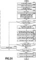
- FIG. 31 is a flowchart showing a procedure of processing performed by the three-dimensional model generation device according to the present embodiment.
- Each piece of processing at S3101 to S3104 is the same as each piece of processing at S2701 to S2704 in the flow in FIG. 27 of the fourth embodiment. Further, each piece of processing at S3105 to S3108 is the same as each piece of processing at S2706 to S2709 in the flow in FIG. 27 described previously. Further, each piece of processing at S3109 and S3110 is the same as each piece of processing at S2705 and S2710 in the flow in FIG. 27 described previously.
- the mask inside/outside determination unit 105 counts the number of cameras for which the selected one voxel is included inside the mask area of the structure mask image of each cameral.
- the weight setting unit 300 adds a value obtained by multiplying the number of cameras for which the selected one mask is included inside the mask area of the structure mask image by 0.5, which is the weight value per camera, to True Count calculated at S3108.
- Each piece of processing at S3113 to S3116 is the same as each piece of processing at S2711 to S2714 in the flow in FIG. 27 described previously. The above is the series of processing in the flow in FIG. 31 .
- FIG. 32 shows an example of True Count in a case where there is no weight addition and an example of True Count in a case where there is weight addition according to the present embodiment for a voxel located in a certain foreground area.
- this voxel is inside the viewing angle of all the 16 cameras, the number of cameras for which the target voxel is included within the foreground mask image is seven, and the number of cameras for which the target voxel is included within the structure mask image is nine. In this case, the number of cameras for which the voxel is outside the integrated mask image is zero (total number of cameras 16 - 7 - 9). Consequently, the number of cameras for which the voxel is outside the integrated mask image and for which the voxel is inside the viewing angle is zero, and therefore, False Count is 0.
- the threshold value of True Count is 70% of the number of cameras for which the target voxel is included inside the viewing angle. Then, the threshold value is 11.2 (16 ⁇ 0.7), and True Count (7) ⁇ the threshold value (11.2) and True Count is less than or equal to the threshold value, and therefore, the voxel is removed.
- the number of cameras for which the target voxel is included within the foreground mask image is seven, and therefore, True Count is similarly 7 and the weight value is added thereto.
- True Count after the weight value is added is 11.5, and True Count (11.5) > the threshold value (11.2) and True Count exceeds the threshold value, and therefore, the voxel is regarded as a foreground and not removed.
- a case where there is one structure is supposed, but in a case where there is a plurality of different structures having a possibility of overlapping a foreground, it may also be possible to set a weight value different for each kind of structure mask image and add a value based on the weight value to True Count.
- the weight value per camera is set to 0.5.
- the weight value per camera is set to 0.3.
- the weight value for the electronic sign is set a value larger than the weight value for the goal.
- the threshold-based determination is performed after adding the weight based on the number of cameras for which the target voxel is included inside the mask area of the structure mask image to True Count. Due to this, even in a case where a foreground is prevented from being captured by a structure in many cameras, it is possible to implement generation of a three-dimensional model with no defect.
- the number of cameras for which the target voxel is included in the structure mask image is used in place of the number of cameras for which the target voxel is included in the foreground mask image (True Count) used in the third embodiment.
- the foreground mask image is updated each time and whether the voxel configuring the three-dimensional model is included in the foreground mask image is determined, and therefore, there is a case where the processing is complicated.
- generation of a three-dimensional model of a foreground not including a structure is performed by counting the number of cameras for which the target voxel is included in the fixed structure mask image for the three-dimensional model generated based on the foreground mask image and the structure mask image.
- FIG. 33 is a diagram showing a configuration of the three-dimensional model generation device 140 in the present embodiment.
- the configuration of the three-dimensional model generation device 140 in the present embodiment is substantially the same as that of the third embodiment, and therefore, explanation of the block that performs the same processing is omitted.
- the three-dimensional model generation device 140 according to the present embodiment includes a mask inside/outside determination unit 3300 in place of the mask inside/outside determination unit 105.
- the mask inside/outside determination unit 3300 counts the number of cameras for which each voxel within the target voxel space is included in the integrated mask image and in the area of the structure mask image, determines whether or not to remove the target voxel by threshold-based determination, and outputs determination results to the foreground model generation unit 107.
- the hardware configuration of the three-dimensional model generation device 140 of the present embodiment is the same as that in FIG. 15 , and therefore, explanation is omitted.
- FIG. 34 is a flowchart showing a procedure of processing performed by the three-dimensional model generation device 140 in the present embodiment.
- Each piece of processing at S3401 to S3407 and S3410 to S3412 is the same as each piece of processing at S1601 to S1607 and S1610 to S1612 explained with reference to FIG. 16 in the third embodiment, and therefore, explanation is omitted and the necessary portions are explained mainly.
- the mask inside/outside determination unit 3300 determines whether or not False Count is more than or equal to a threshold value. In a case where False Count is less than the threshold value, it is possible to determine that the selected voxel is a foreground or a structure, and therefore, the processing advances to S3408.
- the mask inside/outside determination unit 3300 counts the number of cameras for which the pixel or the area corresponding to the selected one voxels is included inside the mask area of the structure mask image of each camera (hereinafter, called Structure Count).
- the mask inside/outside determination unit 3300 determines whether Structure Count is more than or equal to a threshold value. In a case where Structure Count is more than or equal to the threshold value, it is possible to determine that the selected voxel is a structure, and therefore, the processing advances to S3407 and the selected voxel is removed from the target voxel space. On the other hand, in a case where Structure Count is less than the threshold value, it is possible to determine that the selected voxel is a foreground, and therefore, the selected voxel is not removed from the target voxel space.
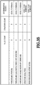
- FIG. 35 shows an example of False Count / Structure Count and determination results of voxels for the person, the leg of the person, the head of the person, the goal, and the other area, respectively, as the foreground, the foreground not detected by a part of the cameras, the foreground hidden by the structure, the structure, and the non-foreground in the virtual viewpoint image generation system shown in FIG. 14 .
- the goal which is a structure
- these are not extracted as the foreground by the foreground separation device 130.
- False Count of the voxel located in the other area except for the person, the leg, the head, and the goal post, which is a structure is 16 and exceeds the threshold value, and therefore, the voxel is removed.
- the three-dimensional model generated by applying the threshold-based determination of False Count is the same as shown in FIG. 23 described previously.
- Structure Count of the voxel located in the area of the goal, which is a structure is 5 and more than or equal to the threshold value, and therefore, the voxel is removed.
- Structure Count of each of the voxels located in the areas of the person, the leg of the person, and the head is 0 and less than the threshold value, and therefore, the voxels are not removed. Consequently, the three-dimensional model of the person with no defect as shown in FIG. 24 described previously is generated.
Claims (20)
- Dispositif de génération destiné à générer des données de forme tridimensionnelle, comprenant :un premier moyen d'acquisition destiné à acquérir une pluralité d'images d'objet indiquant une zone d'objet à l'intérieur d'une pluralité d'images obtenues par une capture d'images depuis une pluralité de directions de capture d'image ;un second moyen d'acquisition destiné à acquérir une pluralité d'images d'une structure immobile présente à l'intérieur d'une scène de capture d'image indiquant une zone de structure affichant une possibilité d'empêcher que l'objet ne soit capturé dans un cas de capture d'image depuis au moins une direction de capture d'image de la pluralité de directions de capture d'image ; etun moyen de génération destiné à générer des données de forme tridimensionnelle correspondant à l'objet de la scène de capture et à la structure sur la base à la fois de la pluralité d'images d'objet indiquant la zone d'objet acquises par le premier moyen d'acquisition et de la pluralité d'images de structure indiquant la zone de structure acquises par le second moyen d'acquisition et à éliminer des données de forme tridimensionnelle correspondant à la structure des données de forme tridimensionnelle générées correspondant à l'objet et à la structure.
- Dispositif de génération selon la revendication 1, comprenant en outre :un moyen de combinaison destiné à combiner l'image indiquant la zone d'objet et l'image indiquant la zone de structure, oùle moyen de génération génère les données de forme tridimensionnelle correspondant à l'objet et à la structure sur la base de l'image combinée par le moyen de combinaison.
- Dispositif de génération selon la revendication 2, dans lequel
le moyen de combinaison génère une image indiquant à la fois la zone d'objet et la zone de structure sur la base de l'image indiquant la zone d'objet et de l'image indiquant la zone de structure. - Dispositif de génération selon la revendication 1, dans lequel
le moyen de génération :génère les données de forme tridimensionnelle correspondant à la structure sur la base de la pluralité d'images de la structure acquises à partir du second moyen d'acquisition ; etgénère les données de forme tridimensionnelle correspondant à l'objet ne comprenant pas les données de forme tridimensionnelle correspondant à la structure sur la base des données de forme tridimensionnelle générées correspondant à la structure et des données de forme tridimensionnelle correspondant à l'objet et à la structure. - Dispositif de génération selon la revendication 4, dans lequel
le moyen de génération génère les données de forme tridimensionnelle correspondant à l'objet ne comprenant pas les données de forme tridimensionnelle correspondant à la structure sur la base des données de forme tridimensionnelle correspondant à l'objet et à la structure et des données de forme tridimensionnelle correspondant à la structure, où au moins une partie de la forme tridimensionnelle de la structure est déployée. - Dispositif de génération selon la revendication 5, dans lequel
le moyen de génération détermine une partie de la structure, qui est déployée, pour les données de forme tridimensionnelle correspondant à la structure conformément à une zone d'un espace tridimensionnel dans lequel est présente la structure. - Dispositif de génération selon la revendication 5 ou 6, dans lequel
le moyen de génération détermine un taux de déploiement pour les données de forme tridimensionnelle correspondant à la structure conformément à une distance entre la structure et l'objet dans un espace tridimensionnel dans lequel est présente la structure. - Dispositif de génération selon la revendication 7, dans lequel
le moyen de génération augmente un taux de déploiement pour les données de forme tridimensionnelle correspondant à la structure à mesure qu'augmente une distance entre la structure et l'objet. - Dispositif de génération selon l'une quelconque des revendications 1 à 8, dans lequel
le moyen de génération détermine un élément correspondant à la structure parmi des éléments formant les données de forme tridimensionnelle générées correspondant à l'objet et à la structure, et
le moyen de génération élimine l'élément déterminé correspondant à la structure des données de forme tridimensionnelle générées correspondant à l'objet et à la structure. - Dispositif de génération selon l'une quelconque des revendications 1 à 8, dans lequel
le moyen de génération détermine un élément correspondant à la structure parmi des éléments formant les données de forme tridimensionnelle générées correspondant à l'objet et à la structure sur la base d'un nombre d'images de structure comprenant une région correspondant à un élément formant les données de forme tridimensionnelle générées correspondant à l'objet et à la structure, et
le moyen de génération élimine l'élément déterminé correspondant à la structure des données de forme tridimensionnelle générées correspondant à l'objet et à la structure. - Dispositif de génération selon l'une quelconque des revendications 1 à 10, dans lequel
l'objet est un objet en mouvement dont la position peut varier à l'intérieur de chaque image dans un cas dans lequel la capture d'images est exécutée de manière chronologique depuis une direction de capture d'images identique. - Dispositif de génération selon l'une quelconque des revendications 1 à 11, dans lequel
l'objet est au moins l'un d'une personne et d'un ballon. - Dispositif de génération selon l'une quelconque des revendications 1 à 12, dans lequel
la structure est un objet dont un état fixe perdure. - Dispositif de génération selon l'une quelconque des revendications 1 à 12, dans lequel
la structure est au moins l'un d'un but de football et d'un drapeau de coin utilisés dans un jeu de football. - Dispositif de génération selon l'une quelconque des revendications 1 à 14, dans lequel
la structure est un objet installé à une position prédéterminée. - Dispositif de génération selon l'une quelconque des revendications 1 à 15, dans lequel
au moins une partie de la structure est installée sur un terrain sur lequel une personne, qui est un objet, joue à un jeu. - Dispositif de génération selon l'une quelconque des revendications 1 à 16, dans lequel
la structure est un objet spécifique. - Procédé mis en œuvre par ordinateur pour générer des données de forme tridimensionnelle, comprenant :une première étape d'acquisition consistant à acquérir une pluralité d'images d'objet indiquant une zone d'objet à l'intérieur d'une pluralité d'images obtenues par une capture d'images depuis une pluralité de directions de capture d'image ;une seconde étape d'acquisition consistant à acquérir une pluralité d'images d'une structure immobile présente à l'intérieur d'une scène de capture d'image indiquant une zone de structure affichant une possibilité d'empêcher que l'objet ne soit capturé dans un cas d'une capture d'image depuis au moins une direction de capture d'image de la pluralité de directions de capture d'image ; etune étape de génération consistant à générer des données de forme tridimensionnelle correspondant à l'objet de la scène de capture et à la structure sur la base à la fois de la pluralité d'images d'objet indiquant la zone d'objet acquises à la première étape d'acquisition et de la pluralité d'images de structure indiquant la zone de structure acquises à la seconde étape d'acquisition et à éliminer des données de forme tridimensionnelle correspondant à la structure des données de forme tridimensionnelle générées correspondant à l'objet et à la structure.
- Procédé de génération selon la revendication 18, comprenant en outre :une étape de combinaison consistant à combiner l'image indiquant la zone d'objet et l'image indiquant la zone de structure, oùà l'étape de génération, les données de forme tridimensionnelle correspondant à l'objet et à la structure sont générées sur la base de l'image combinée à l'étape de combinaison.
- Programme informatique destiné à amener un ordinateur à fonctionner en tant que le dispositif de génération selon l'une quelconque des revendications 1 à 17.
Priority Applications (1)
| Application Number | Priority Date | Filing Date | Title |
|---|---|---|---|
| EP21173382.9A EP3901910A1 (fr) | 2017-12-14 | 2018-12-03 | Dispositif de génération et procédé de génération et programme de modèle tridimensionnel |
Applications Claiming Priority (4)
| Application Number | Priority Date | Filing Date | Title |
|---|---|---|---|
| JP2017239891A JP6403862B1 (ja) | 2017-12-14 | 2017-12-14 | 3次元モデルの生成装置、生成方法及びプログラム |
| JP2018089467 | 2018-05-07 | ||
| JP2018209196A JP7265825B2 (ja) | 2018-05-07 | 2018-11-06 | 生成装置、生成方法およびプログラム |
| PCT/JP2018/044373 WO2019116942A1 (fr) | 2017-12-14 | 2018-12-03 | Dispositif de génération, et procédé de génération et programme de modèle tridimensionnel |
Related Child Applications (1)
| Application Number | Title | Priority Date | Filing Date |
|---|---|---|---|
| EP21173382.9A Division EP3901910A1 (fr) | 2017-12-14 | 2018-12-03 | Dispositif de génération et procédé de génération et programme de modèle tridimensionnel |
Publications (3)
| Publication Number | Publication Date |
|---|---|
| EP3608873A1 EP3608873A1 (fr) | 2020-02-12 |
| EP3608873A4 EP3608873A4 (fr) | 2020-05-27 |
| EP3608873B1 true EP3608873B1 (fr) | 2021-06-09 |
Family
ID=68615459
Family Applications (2)
| Application Number | Title | Priority Date | Filing Date |
|---|---|---|---|
| EP21173382.9A Pending EP3901910A1 (fr) | 2017-12-14 | 2018-12-03 | Dispositif de génération et procédé de génération et programme de modèle tridimensionnel |
| EP18887303.8A Active EP3608873B1 (fr) | 2017-12-14 | 2018-12-03 | Dispositif de génération, et procédé de génération et programme de modèle tridimensionnel |
Family Applications Before (1)
| Application Number | Title | Priority Date | Filing Date |
|---|---|---|---|
| EP21173382.9A Pending EP3901910A1 (fr) | 2017-12-14 | 2018-12-03 | Dispositif de génération et procédé de génération et programme de modèle tridimensionnel |
Country Status (8)
| Country | Link |
|---|---|
| US (1) | US11151787B2 (fr) |
| EP (2) | EP3901910A1 (fr) |
| KR (2) | KR102178239B1 (fr) |
| CN (2) | CN110622215B (fr) |
| BR (1) | BR112019022798A2 (fr) |
| CA (1) | CA3061699C (fr) |
| ES (1) | ES2881320T3 (fr) |
| RU (1) | RU2744699C1 (fr) |
Families Citing this family (8)
| Publication number | Priority date | Publication date | Assignee | Title |
|---|---|---|---|---|
| US11407111B2 (en) * | 2018-06-27 | 2022-08-09 | Abb Schweiz Ag | Method and system to generate a 3D model for a robot scene |
| US10715714B2 (en) * | 2018-10-17 | 2020-07-14 | Verizon Patent And Licensing, Inc. | Machine learning-based device placement and configuration service |
| CN111681212B (zh) * | 2020-05-21 | 2022-05-03 | 中山大学 | 一种基于激光雷达点云数据的三维目标检测方法 |
| CN112634439B (zh) * | 2020-12-25 | 2023-10-31 | 北京奇艺世纪科技有限公司 | 一种3d信息展示方法及装置 |
| CN113223095B (zh) * | 2021-05-25 | 2022-06-17 | 中国人民解放军63660部队 | 一种基于已知相机位置内外参数标定方法 |
| CN113538562B (zh) * | 2021-07-16 | 2022-05-13 | 贝壳找房(北京)科技有限公司 | 室内面积确定方法、装置以及电子设备、存储介质 |
| JP2023013538A (ja) * | 2021-07-16 | 2023-01-26 | キヤノン株式会社 | 画像処理装置、画像処理方法、及びプログラム |
| CN115657855A (zh) * | 2022-11-10 | 2023-01-31 | 北京有竹居网络技术有限公司 | 人机交互的方法、装置、设备和存储介质 |
Family Cites Families (39)
| Publication number | Priority date | Publication date | Assignee | Title |
|---|---|---|---|---|
| JPH09134449A (ja) * | 1995-11-09 | 1997-05-20 | Ainesu:Kk | 立体モデルのテクスチャマッピング方法 |
| JP3813343B2 (ja) * | 1997-09-09 | 2006-08-23 | 三洋電機株式会社 | 3次元モデリング装置 |
| US20020051491A1 (en) * | 1998-11-20 | 2002-05-02 | Kiran Challapali | Extraction of foreground information for video conference |
| CN1326087C (zh) * | 1999-12-28 | 2007-07-11 | 索尼公司 | 信号处理方法与设备以及记录介质 |
| KR100415266B1 (ko) | 2000-05-11 | 2004-01-16 | 가부시끼가이샤 도시바 | 물체영역정보 기술방법과 물체영역정보 생성장치 및 기록매체 |
| RU2276407C2 (ru) * | 2001-10-22 | 2006-05-10 | Интел Зао | Способ и устройство для сегментации фона на основе локализации движения |
| AU2003277240A1 (en) | 2002-10-15 | 2004-06-07 | University Of Southern California | Augmented virtual environments |
| CN1950844A (zh) | 2004-03-03 | 2007-04-18 | 日本电气株式会社 | 物体的姿势推断及对照系统和方法及其程序 |
| KR20070010895A (ko) * | 2005-07-20 | 2007-01-24 | 주식회사 팬택 | 스포츠 경기 데이터를 그래픽 영상으로 구현하는 방법 및이동 통신 단말기 |
| EP1862969A1 (fr) * | 2006-06-02 | 2007-12-05 | Eidgenössische Technische Hochschule Zürich | Procédé et système de création de la représentation d'une scène 3D dynamiquement modifiée |
| JP4839237B2 (ja) | 2007-02-07 | 2011-12-21 | 日本電信電話株式会社 | 3次元形状復元方法,3次元形状復元装置,その方法を実装した3次元形状復元プログラム及びそのプログラムを記録した記録媒体 |
| GB2452508A (en) * | 2007-09-05 | 2009-03-11 | Sony Corp | Generating a three-dimensional representation of a sports game |
| US8073190B2 (en) * | 2007-11-16 | 2011-12-06 | Sportvision, Inc. | 3D textured objects for virtual viewpoint animations |
| GB2455313B (en) * | 2007-12-04 | 2012-06-13 | Sony Corp | Apparatus and method for estimating orientation |
| JP5249114B2 (ja) * | 2009-04-03 | 2013-07-31 | Kddi株式会社 | 画像生成装置、方法及びプログラム |
| WO2011039679A1 (fr) * | 2009-10-02 | 2011-04-07 | Koninklijke Philips Electronics N.V. | Sélection de points de vue pour la génération de vues supplémentaires dans une vidéo tridimensionnelle |
| WO2011121117A1 (fr) * | 2010-04-02 | 2011-10-06 | Imec | Système de caméra virtuelle |
| JP5944904B2 (ja) | 2010-09-20 | 2016-07-05 | フラウンホーファーゲゼルシャフト ツール フォルデルング デル アンゲヴァンテン フォルシユング エー.フアー. | 風景の背景と前景とを区別する方法、及び風景の画像において背景を置き換える方法 |
| JP5580164B2 (ja) * | 2010-10-18 | 2014-08-27 | 株式会社トプコン | 光学情報処理装置、光学情報処理方法、光学情報処理システム、光学情報処理プログラム |
| JP5279875B2 (ja) | 2011-07-14 | 2013-09-04 | 株式会社エヌ・ティ・ティ・ドコモ | オブジェクト表示装置、オブジェクト表示方法及びオブジェクト表示プログラム |
| JP5414906B2 (ja) | 2011-08-05 | 2014-02-12 | 株式会社東芝 | 画像処理装置、画像表示装置、画像処理方法およびプログラム |
| US9087408B2 (en) | 2011-08-16 | 2015-07-21 | Google Inc. | Systems and methods for generating depthmaps |
| JP5809607B2 (ja) | 2012-07-03 | 2015-11-11 | 日本電信電話株式会社 | 画像処理装置、画像処理方法及び画像処理プログラム |
| JP2015074436A (ja) | 2013-10-11 | 2015-04-20 | 富士通株式会社 | 画像処理装置、画像処理方法、及び、プログラム |
| PT3357449T (pt) | 2013-12-09 | 2019-05-23 | Bien Air Holding Sa | Turbina para uma peça de mão dentária ou cirúrgica de ar comprimido |
| JP6309749B2 (ja) * | 2013-12-09 | 2018-04-11 | シャープ株式会社 | 画像データ再生装置および画像データ生成装置 |
| US9171403B2 (en) | 2014-02-13 | 2015-10-27 | Microsoft Technology Licensing, Llc | Contour completion for augmenting surface reconstructions |
| US9852238B2 (en) | 2014-04-24 | 2017-12-26 | The Board Of Trustees Of The University Of Illinois | 4D vizualization of building design and construction modeling with photographs |
| US10477189B2 (en) * | 2014-04-30 | 2019-11-12 | Intel Corporation | System and method of multi-view reconstruction with user-selectable novel views |
| JP6587435B2 (ja) | 2015-06-29 | 2019-10-09 | キヤノン株式会社 | 画像処理装置、情報処理方法及びプログラム |
| KR101785517B1 (ko) * | 2015-08-26 | 2017-10-16 | 삼성중공업(주) | 족장 정보 제공 장치 및 방법 |
| US9569812B1 (en) * | 2016-01-07 | 2017-02-14 | Microsoft Technology Licensing, Llc | View rendering from multiple server-side renderings |
| US10210660B2 (en) | 2016-04-06 | 2019-02-19 | Facebook, Inc. | Removing occlusion in camera views |
| JP6808357B2 (ja) * | 2016-05-25 | 2021-01-06 | キヤノン株式会社 | 情報処理装置、制御方法、及び、プログラム |
| JP6882868B2 (ja) * | 2016-08-12 | 2021-06-02 | キヤノン株式会社 | 画像処理装置、画像処理方法、システム |
| US10559095B2 (en) * | 2016-08-31 | 2020-02-11 | Canon Kabushiki Kaisha | Image processing apparatus, image processing method, and medium |
| US10389935B2 (en) * | 2016-12-13 | 2019-08-20 | Canon Kabushiki Kaisha | Method, system and apparatus for configuring a virtual camera |
| JP6871801B2 (ja) * | 2017-05-11 | 2021-05-12 | キヤノン株式会社 | 画像処理装置、画像処理方法、情報処理装置、撮像装置および画像処理システム |
| JP7285834B2 (ja) * | 2018-06-19 | 2023-06-02 | パナソニック インテレクチュアル プロパティ コーポレーション オブ アメリカ | 三次元再構成方法および三次元再構成装置 |
-
2018
- 2018-12-03 ES ES18887303T patent/ES2881320T3/es active Active
- 2018-12-03 EP EP21173382.9A patent/EP3901910A1/fr active Pending
- 2018-12-03 CA CA3061699A patent/CA3061699C/fr active Active
- 2018-12-03 CN CN201880028645.2A patent/CN110622215B/zh active Active
- 2018-12-03 CN CN202110824521.9A patent/CN113593012A/zh active Pending
- 2018-12-03 KR KR1020197032124A patent/KR102178239B1/ko active IP Right Grant
- 2018-12-03 EP EP18887303.8A patent/EP3608873B1/fr active Active
- 2018-12-03 BR BR112019022798-9A patent/BR112019022798A2/pt unknown
- 2018-12-03 RU RU2019134216A patent/RU2744699C1/ru active
- 2018-12-03 KR KR1020207032192A patent/KR102254407B1/ko active IP Right Grant
-
2019
- 2019-10-24 US US16/663,019 patent/US11151787B2/en active Active
Also Published As
| Publication number | Publication date |
|---|---|
| CN110622215B (zh) | 2021-07-23 |
| US20200058167A1 (en) | 2020-02-20 |
| KR102254407B1 (ko) | 2021-05-24 |
| CA3061699A1 (fr) | 2019-10-28 |
| US11151787B2 (en) | 2021-10-19 |
| ES2881320T3 (es) | 2021-11-29 |
| KR20200129184A (ko) | 2020-11-17 |
| KR20190136042A (ko) | 2019-12-09 |
| KR102178239B1 (ko) | 2020-11-12 |
| EP3608873A1 (fr) | 2020-02-12 |
| CN113593012A (zh) | 2021-11-02 |
| EP3608873A4 (fr) | 2020-05-27 |
| EP3901910A1 (fr) | 2021-10-27 |
| CA3061699C (fr) | 2023-03-07 |
| RU2744699C1 (ru) | 2021-03-15 |
| BR112019022798A2 (pt) | 2020-05-26 |
| CN110622215A (zh) | 2019-12-27 |
Similar Documents
| Publication | Publication Date | Title |
|---|---|---|
| EP3608873B1 (fr) | Dispositif de génération, et procédé de génération et programme de modèle tridimensionnel | |
| US11354840B2 (en) | Three dimensional acquisition and rendering | |
| US10789765B2 (en) | Three-dimensional reconstruction method | |
| Alexiadis et al. | An integrated platform for live 3D human reconstruction and motion capturing | |
| KR102153985B1 (ko) | 가상 시점 화상을 생성하는 장치, 시스템, 방법, 및 비일시적 컴퓨터 판독가능 기억 매체 | |
| US11798233B2 (en) | Generation device, generation method and storage medium for three-dimensional model that remove a portion of the three-dimensional model | |
| KR20190034092A (ko) | 화상처리 장치, 화상처리 방법, 화상처리 시스템 및 기억매체 | |
| WO2018135510A1 (fr) | Procédé de reconstruction tridimensionnelle et dispositif de reconstruction tridimensionnelle | |
| CN107798702B (zh) | 一种用于增强现实的实时图像叠加方法以及装置 | |
| JP7170224B2 (ja) | 三次元生成方法および三次元生成装置 | |
| JP2019106145A (ja) | 3次元モデルの生成装置、生成方法及びプログラム | |
| CN107798703B (zh) | 一种用于增强现实的实时图像叠加方法以及装置 | |
| JP2011146762A (ja) | 立体モデル生成装置 | |
| JP2019106170A (ja) | 3次元モデルの生成装置、生成方法及びプログラム | |
| JP7265825B2 (ja) | 生成装置、生成方法およびプログラム | |
| JP7353527B2 (ja) | 情報処理装置、情報処理装置の制御方法およびプログラム | |
| JP2011149952A (ja) | モデル入力装置およびモデル生成システム | |
| JP2023026244A (ja) | 画像生成装置および画像生成方法、プログラム | |
| JP2021092891A (ja) | 情報処理装置、情報処理方法、画像処理システム及びプログラム | |
| JP2022094788A (ja) | 生成装置、生成方法、及び、プログラム | |
| JP2019114269A (ja) | 仮想視点画像を生成するシステム、方法及びプログラム | |
| Matsuyama | Ubiquitous and wearable vision systems |
Legal Events
| Date | Code | Title | Description |
|---|---|---|---|
| STAA | Information on the status of an ep patent application or granted ep patent |
Free format text: STATUS: THE INTERNATIONAL PUBLICATION HAS BEEN MADE |
|
| PUAI | Public reference made under article 153(3) epc to a published international application that has entered the european phase |
Free format text: ORIGINAL CODE: 0009012 |
|
| STAA | Information on the status of an ep patent application or granted ep patent |
Free format text: STATUS: REQUEST FOR EXAMINATION WAS MADE |
|
| 17P | Request for examination filed |
Effective date: 20191106 |
|
| AK | Designated contracting states |
Kind code of ref document: A1 Designated state(s): AL AT BE BG CH CY CZ DE DK EE ES FI FR GB GR HR HU IE IS IT LI LT LU LV MC MK MT NL NO PL PT RO RS SE SI SK SM TR |
|
| AX | Request for extension of the european patent |
Extension state: BA ME |
|
| A4 | Supplementary search report drawn up and despatched |
Effective date: 20200424 |
|
| RIC1 | Information provided on ipc code assigned before grant |
Ipc: G06T 17/00 20060101ALI20200420BHEP Ipc: H04N 5/232 20060101ALI20200420BHEP Ipc: G06T 1/00 20060101ALI20200420BHEP Ipc: G06T 5/50 20060101ALI20200420BHEP Ipc: G06T 7/55 20170101AFI20200420BHEP Ipc: H04N 7/18 20060101ALI20200420BHEP |
|
| STAA | Information on the status of an ep patent application or granted ep patent |
Free format text: STATUS: EXAMINATION IS IN PROGRESS |
|
| 17Q | First examination report despatched |
Effective date: 20200609 |
|
| GRAP | Despatch of communication of intention to grant a patent |
Free format text: ORIGINAL CODE: EPIDOSNIGR1 |
|
| STAA | Information on the status of an ep patent application or granted ep patent |
Free format text: STATUS: GRANT OF PATENT IS INTENDED |
|
| DAV | Request for validation of the european patent (deleted) | ||
| DAX | Request for extension of the european patent (deleted) | ||
| INTG | Intention to grant announced |
Effective date: 20210115 |
|
| GRAS | Grant fee paid |
Free format text: ORIGINAL CODE: EPIDOSNIGR3 |
|
| GRAA | (expected) grant |
Free format text: ORIGINAL CODE: 0009210 |
|
| STAA | Information on the status of an ep patent application or granted ep patent |
Free format text: STATUS: THE PATENT HAS BEEN GRANTED |
|
| AK | Designated contracting states |
Kind code of ref document: B1 Designated state(s): AL AT BE BG CH CY CZ DE DK EE ES FI FR GB GR HR HU IE IS IT LI LT LU LV MC MK MT NL NO PL PT RO RS SE SI SK SM TR |
|
| REG | Reference to a national code |
Ref country code: GB Ref legal event code: FG4D |
|
| REG | Reference to a national code |
Ref country code: CH Ref legal event code: EP Ref country code: AT Ref legal event code: REF Ref document number: 1401122 Country of ref document: AT Kind code of ref document: T Effective date: 20210615 |
|
| REG | Reference to a national code |
Ref country code: DE Ref legal event code: R096 Ref document number: 602018018510 Country of ref document: DE |
|
| REG | Reference to a national code |
Ref country code: IE Ref legal event code: FG4D |
|
| REG | Reference to a national code |
Ref country code: LT Ref legal event code: MG9D |
|
| PG25 | Lapsed in a contracting state [announced via postgrant information from national office to epo] |
Ref country code: BG Free format text: LAPSE BECAUSE OF FAILURE TO SUBMIT A TRANSLATION OF THE DESCRIPTION OR TO PAY THE FEE WITHIN THE PRESCRIBED TIME-LIMIT Effective date: 20210909 Ref country code: LT Free format text: LAPSE BECAUSE OF FAILURE TO SUBMIT A TRANSLATION OF THE DESCRIPTION OR TO PAY THE FEE WITHIN THE PRESCRIBED TIME-LIMIT Effective date: 20210609 Ref country code: HR Free format text: LAPSE BECAUSE OF FAILURE TO SUBMIT A TRANSLATION OF THE DESCRIPTION OR TO PAY THE FEE WITHIN THE PRESCRIBED TIME-LIMIT Effective date: 20210609 Ref country code: FI Free format text: LAPSE BECAUSE OF FAILURE TO SUBMIT A TRANSLATION OF THE DESCRIPTION OR TO PAY THE FEE WITHIN THE PRESCRIBED TIME-LIMIT Effective date: 20210609 |
|
| REG | Reference to a national code |
Ref country code: AT Ref legal event code: MK05 Ref document number: 1401122 Country of ref document: AT Kind code of ref document: T Effective date: 20210609 |
|
| REG | Reference to a national code |
Ref country code: NL Ref legal event code: MP Effective date: 20210609 |
|
| REG | Reference to a national code |
Ref country code: ES Ref legal event code: FG2A Ref document number: 2881320 Country of ref document: ES Kind code of ref document: T3 Effective date: 20211129 |
|
| PG25 | Lapsed in a contracting state [announced via postgrant information from national office to epo] |
Ref country code: GR Free format text: LAPSE BECAUSE OF FAILURE TO SUBMIT A TRANSLATION OF THE DESCRIPTION OR TO PAY THE FEE WITHIN THE PRESCRIBED TIME-LIMIT Effective date: 20210910 Ref country code: LV Free format text: LAPSE BECAUSE OF FAILURE TO SUBMIT A TRANSLATION OF THE DESCRIPTION OR TO PAY THE FEE WITHIN THE PRESCRIBED TIME-LIMIT Effective date: 20210609 Ref country code: NO Free format text: LAPSE BECAUSE OF FAILURE TO SUBMIT A TRANSLATION OF THE DESCRIPTION OR TO PAY THE FEE WITHIN THE PRESCRIBED TIME-LIMIT Effective date: 20210909 Ref country code: RS Free format text: LAPSE BECAUSE OF FAILURE TO SUBMIT A TRANSLATION OF THE DESCRIPTION OR TO PAY THE FEE WITHIN THE PRESCRIBED TIME-LIMIT Effective date: 20210609 Ref country code: SE Free format text: LAPSE BECAUSE OF FAILURE TO SUBMIT A TRANSLATION OF THE DESCRIPTION OR TO PAY THE FEE WITHIN THE PRESCRIBED TIME-LIMIT Effective date: 20210609 |
|
| PG25 | Lapsed in a contracting state [announced via postgrant information from national office to epo] |
Ref country code: CZ Free format text: LAPSE BECAUSE OF FAILURE TO SUBMIT A TRANSLATION OF THE DESCRIPTION OR TO PAY THE FEE WITHIN THE PRESCRIBED TIME-LIMIT Effective date: 20210609 Ref country code: AT Free format text: LAPSE BECAUSE OF FAILURE TO SUBMIT A TRANSLATION OF THE DESCRIPTION OR TO PAY THE FEE WITHIN THE PRESCRIBED TIME-LIMIT Effective date: 20210609 Ref country code: NL Free format text: LAPSE BECAUSE OF FAILURE TO SUBMIT A TRANSLATION OF THE DESCRIPTION OR TO PAY THE FEE WITHIN THE PRESCRIBED TIME-LIMIT Effective date: 20210609 Ref country code: PT Free format text: LAPSE BECAUSE OF FAILURE TO SUBMIT A TRANSLATION OF THE DESCRIPTION OR TO PAY THE FEE WITHIN THE PRESCRIBED TIME-LIMIT Effective date: 20211011 Ref country code: RO Free format text: LAPSE BECAUSE OF FAILURE TO SUBMIT A TRANSLATION OF THE DESCRIPTION OR TO PAY THE FEE WITHIN THE PRESCRIBED TIME-LIMIT Effective date: 20210609 Ref country code: SM Free format text: LAPSE BECAUSE OF FAILURE TO SUBMIT A TRANSLATION OF THE DESCRIPTION OR TO PAY THE FEE WITHIN THE PRESCRIBED TIME-LIMIT Effective date: 20210609 Ref country code: SK Free format text: LAPSE BECAUSE OF FAILURE TO SUBMIT A TRANSLATION OF THE DESCRIPTION OR TO PAY THE FEE WITHIN THE PRESCRIBED TIME-LIMIT Effective date: 20210609 Ref country code: EE Free format text: LAPSE BECAUSE OF FAILURE TO SUBMIT A TRANSLATION OF THE DESCRIPTION OR TO PAY THE FEE WITHIN THE PRESCRIBED TIME-LIMIT Effective date: 20210609 |
|
| PG25 | Lapsed in a contracting state [announced via postgrant information from national office to epo] |
Ref country code: PL Free format text: LAPSE BECAUSE OF FAILURE TO SUBMIT A TRANSLATION OF THE DESCRIPTION OR TO PAY THE FEE WITHIN THE PRESCRIBED TIME-LIMIT Effective date: 20210609 |
|
| REG | Reference to a national code |
Ref country code: DE Ref legal event code: R097 Ref document number: 602018018510 Country of ref document: DE |
|
| PLBE | No opposition filed within time limit |
Free format text: ORIGINAL CODE: 0009261 |
|
| STAA | Information on the status of an ep patent application or granted ep patent |
Free format text: STATUS: NO OPPOSITION FILED WITHIN TIME LIMIT |
|
| PG25 | Lapsed in a contracting state [announced via postgrant information from national office to epo] |
Ref country code: DK Free format text: LAPSE BECAUSE OF FAILURE TO SUBMIT A TRANSLATION OF THE DESCRIPTION OR TO PAY THE FEE WITHIN THE PRESCRIBED TIME-LIMIT Effective date: 20210609 |
|
| 26N | No opposition filed |
Effective date: 20220310 |
|
| PG25 | Lapsed in a contracting state [announced via postgrant information from national office to epo] |
Ref country code: AL Free format text: LAPSE BECAUSE OF FAILURE TO SUBMIT A TRANSLATION OF THE DESCRIPTION OR TO PAY THE FEE WITHIN THE PRESCRIBED TIME-LIMIT Effective date: 20210609 |
|
| PG25 | Lapsed in a contracting state [announced via postgrant information from national office to epo] |
Ref country code: MC Free format text: LAPSE BECAUSE OF FAILURE TO SUBMIT A TRANSLATION OF THE DESCRIPTION OR TO PAY THE FEE WITHIN THE PRESCRIBED TIME-LIMIT Effective date: 20210609 |
|
| REG | Reference to a national code |
Ref country code: CH Ref legal event code: PL |
|
| REG | Reference to a national code |
Ref country code: BE Ref legal event code: MM Effective date: 20211231 |
|
| PG25 | Lapsed in a contracting state [announced via postgrant information from national office to epo] |
Ref country code: LU Free format text: LAPSE BECAUSE OF NON-PAYMENT OF DUE FEES Effective date: 20211203 Ref country code: IE Free format text: LAPSE BECAUSE OF NON-PAYMENT OF DUE FEES Effective date: 20211203 |
|
| PG25 | Lapsed in a contracting state [announced via postgrant information from national office to epo] |
Ref country code: BE Free format text: LAPSE BECAUSE OF NON-PAYMENT OF DUE FEES Effective date: 20211231 |
|
| PG25 | Lapsed in a contracting state [announced via postgrant information from national office to epo] |
Ref country code: LI Free format text: LAPSE BECAUSE OF NON-PAYMENT OF DUE FEES Effective date: 20211231 Ref country code: CH Free format text: LAPSE BECAUSE OF NON-PAYMENT OF DUE FEES Effective date: 20211231 |
|
| PGFP | Annual fee paid to national office [announced via postgrant information from national office to epo] |
Ref country code: IT Payment date: 20221122 Year of fee payment: 5 |
|
| PGFP | Annual fee paid to national office [announced via postgrant information from national office to epo] |
Ref country code: ES Payment date: 20230102 Year of fee payment: 5 |
|
| PG25 | Lapsed in a contracting state [announced via postgrant information from national office to epo] |
Ref country code: CY Free format text: LAPSE BECAUSE OF FAILURE TO SUBMIT A TRANSLATION OF THE DESCRIPTION OR TO PAY THE FEE WITHIN THE PRESCRIBED TIME-LIMIT Effective date: 20210609 |
|
| PG25 | Lapsed in a contracting state [announced via postgrant information from national office to epo] |
Ref country code: HU Free format text: LAPSE BECAUSE OF FAILURE TO SUBMIT A TRANSLATION OF THE DESCRIPTION OR TO PAY THE FEE WITHIN THE PRESCRIBED TIME-LIMIT; INVALID AB INITIO Effective date: 20181203 |
|
| PGFP | Annual fee paid to national office [announced via postgrant information from national office to epo] |
Ref country code: GB Payment date: 20231121 Year of fee payment: 6 |
|
| PGFP | Annual fee paid to national office [announced via postgrant information from national office to epo] |
Ref country code: FR Payment date: 20231122 Year of fee payment: 6 Ref country code: DE Payment date: 20231121 Year of fee payment: 6 |
|
| PGFP | Annual fee paid to national office [announced via postgrant information from national office to epo] |
Ref country code: ES Payment date: 20240102 Year of fee payment: 6 |
|
| PG25 | Lapsed in a contracting state [announced via postgrant information from national office to epo] |
Ref country code: MK Free format text: LAPSE BECAUSE OF FAILURE TO SUBMIT A TRANSLATION OF THE DESCRIPTION OR TO PAY THE FEE WITHIN THE PRESCRIBED TIME-LIMIT Effective date: 20210609 |