EP3608714A1 - Lens driving unit, and camera module and optical apparatus including same - Google Patents
Lens driving unit, and camera module and optical apparatus including same Download PDFInfo
- Publication number
- EP3608714A1 EP3608714A1 EP18781034.6A EP18781034A EP3608714A1 EP 3608714 A1 EP3608714 A1 EP 3608714A1 EP 18781034 A EP18781034 A EP 18781034A EP 3608714 A1 EP3608714 A1 EP 3608714A1
- Authority
- EP
- European Patent Office
- Prior art keywords
- housing
- disposed
- coil
- coupling portion
- extension
- Prior art date
- Legal status (The legal status is an assumption and is not a legal conclusion. Google has not performed a legal analysis and makes no representation as to the accuracy of the status listed.)
- Granted
Links
Images




Classifications
-
- G—PHYSICS
- G02—OPTICS
- G02B—OPTICAL ELEMENTS, SYSTEMS OR APPARATUS
- G02B7/00—Mountings, adjusting means, or light-tight connections, for optical elements
- G02B7/02—Mountings, adjusting means, or light-tight connections, for optical elements for lenses
- G02B7/04—Mountings, adjusting means, or light-tight connections, for optical elements for lenses with mechanism for focusing or varying magnification
- G02B7/08—Mountings, adjusting means, or light-tight connections, for optical elements for lenses with mechanism for focusing or varying magnification adapted to co-operate with a remote control mechanism
-
- H—ELECTRICITY
- H04—ELECTRIC COMMUNICATION TECHNIQUE
- H04N—PICTORIAL COMMUNICATION, e.g. TELEVISION
- H04N23/00—Cameras or camera modules comprising electronic image sensors; Control thereof
- H04N23/50—Constructional details
- H04N23/54—Mounting of pick-up tubes, electronic image sensors, deviation or focusing coils
-
- G—PHYSICS
- G02—OPTICS
- G02B—OPTICAL ELEMENTS, SYSTEMS OR APPARATUS
- G02B27/00—Optical systems or apparatus not provided for by any of the groups G02B1/00 - G02B26/00, G02B30/00
- G02B27/64—Imaging systems using optical elements for stabilisation of the lateral and angular position of the image
- G02B27/646—Imaging systems using optical elements for stabilisation of the lateral and angular position of the image compensating for small deviations, e.g. due to vibration or shake
-
- G—PHYSICS
- G03—PHOTOGRAPHY; CINEMATOGRAPHY; ANALOGOUS TECHNIQUES USING WAVES OTHER THAN OPTICAL WAVES; ELECTROGRAPHY; HOLOGRAPHY
- G03B—APPARATUS OR ARRANGEMENTS FOR TAKING PHOTOGRAPHS OR FOR PROJECTING OR VIEWING THEM; APPARATUS OR ARRANGEMENTS EMPLOYING ANALOGOUS TECHNIQUES USING WAVES OTHER THAN OPTICAL WAVES; ACCESSORIES THEREFOR
- G03B17/00—Details of cameras or camera bodies; Accessories therefor
- G03B17/02—Bodies
- G03B17/12—Bodies with means for supporting objectives, supplementary lenses, filters, masks, or turrets
-
- G—PHYSICS
- G03—PHOTOGRAPHY; CINEMATOGRAPHY; ANALOGOUS TECHNIQUES USING WAVES OTHER THAN OPTICAL WAVES; ELECTROGRAPHY; HOLOGRAPHY
- G03B—APPARATUS OR ARRANGEMENTS FOR TAKING PHOTOGRAPHS OR FOR PROJECTING OR VIEWING THEM; APPARATUS OR ARRANGEMENTS EMPLOYING ANALOGOUS TECHNIQUES USING WAVES OTHER THAN OPTICAL WAVES; ACCESSORIES THEREFOR
- G03B30/00—Camera modules comprising integrated lens units and imaging units, specially adapted for being embedded in other devices, e.g. mobile phones or vehicles
-
- G—PHYSICS
- G03—PHOTOGRAPHY; CINEMATOGRAPHY; ANALOGOUS TECHNIQUES USING WAVES OTHER THAN OPTICAL WAVES; ELECTROGRAPHY; HOLOGRAPHY
- G03B—APPARATUS OR ARRANGEMENTS FOR TAKING PHOTOGRAPHS OR FOR PROJECTING OR VIEWING THEM; APPARATUS OR ARRANGEMENTS EMPLOYING ANALOGOUS TECHNIQUES USING WAVES OTHER THAN OPTICAL WAVES; ACCESSORIES THEREFOR
- G03B5/00—Adjustment of optical system relative to image or object surface other than for focusing
-
- G—PHYSICS
- G03—PHOTOGRAPHY; CINEMATOGRAPHY; ANALOGOUS TECHNIQUES USING WAVES OTHER THAN OPTICAL WAVES; ELECTROGRAPHY; HOLOGRAPHY
- G03B—APPARATUS OR ARRANGEMENTS FOR TAKING PHOTOGRAPHS OR FOR PROJECTING OR VIEWING THEM; APPARATUS OR ARRANGEMENTS EMPLOYING ANALOGOUS TECHNIQUES USING WAVES OTHER THAN OPTICAL WAVES; ACCESSORIES THEREFOR
- G03B5/00—Adjustment of optical system relative to image or object surface other than for focusing
- G03B5/02—Lateral adjustment of lens
-
- H—ELECTRICITY
- H01—ELECTRIC ELEMENTS
- H01F—MAGNETS; INDUCTANCES; TRANSFORMERS; SELECTION OF MATERIALS FOR THEIR MAGNETIC PROPERTIES
- H01F7/00—Magnets
- H01F7/06—Electromagnets; Actuators including electromagnets
-
- H—ELECTRICITY
- H04—ELECTRIC COMMUNICATION TECHNIQUE
- H04N—PICTORIAL COMMUNICATION, e.g. TELEVISION
- H04N23/00—Cameras or camera modules comprising electronic image sensors; Control thereof
- H04N23/50—Constructional details
- H04N23/55—Optical parts specially adapted for electronic image sensors; Mounting thereof
-
- G—PHYSICS
- G03—PHOTOGRAPHY; CINEMATOGRAPHY; ANALOGOUS TECHNIQUES USING WAVES OTHER THAN OPTICAL WAVES; ELECTROGRAPHY; HOLOGRAPHY
- G03B—APPARATUS OR ARRANGEMENTS FOR TAKING PHOTOGRAPHS OR FOR PROJECTING OR VIEWING THEM; APPARATUS OR ARRANGEMENTS EMPLOYING ANALOGOUS TECHNIQUES USING WAVES OTHER THAN OPTICAL WAVES; ACCESSORIES THEREFOR
- G03B1/00—Film strip handling
- G03B1/02—Moving film strip by pull on end thereof
-
- G—PHYSICS
- G03—PHOTOGRAPHY; CINEMATOGRAPHY; ANALOGOUS TECHNIQUES USING WAVES OTHER THAN OPTICAL WAVES; ELECTROGRAPHY; HOLOGRAPHY
- G03B—APPARATUS OR ARRANGEMENTS FOR TAKING PHOTOGRAPHS OR FOR PROJECTING OR VIEWING THEM; APPARATUS OR ARRANGEMENTS EMPLOYING ANALOGOUS TECHNIQUES USING WAVES OTHER THAN OPTICAL WAVES; ACCESSORIES THEREFOR
- G03B13/00—Viewfinders; Focusing aids for cameras; Means for focusing for cameras; Autofocus systems for cameras
- G03B13/32—Means for focusing
- G03B13/34—Power focusing
- G03B13/36—Autofocus systems
-
- G—PHYSICS
- G03—PHOTOGRAPHY; CINEMATOGRAPHY; ANALOGOUS TECHNIQUES USING WAVES OTHER THAN OPTICAL WAVES; ELECTROGRAPHY; HOLOGRAPHY
- G03B—APPARATUS OR ARRANGEMENTS FOR TAKING PHOTOGRAPHS OR FOR PROJECTING OR VIEWING THEM; APPARATUS OR ARRANGEMENTS EMPLOYING ANALOGOUS TECHNIQUES USING WAVES OTHER THAN OPTICAL WAVES; ACCESSORIES THEREFOR
- G03B2205/00—Adjustment of optical system relative to image or object surface other than for focusing
- G03B2205/0007—Movement of one or more optical elements for control of motion blur
-
- G—PHYSICS
- G03—PHOTOGRAPHY; CINEMATOGRAPHY; ANALOGOUS TECHNIQUES USING WAVES OTHER THAN OPTICAL WAVES; ELECTROGRAPHY; HOLOGRAPHY
- G03B—APPARATUS OR ARRANGEMENTS FOR TAKING PHOTOGRAPHS OR FOR PROJECTING OR VIEWING THEM; APPARATUS OR ARRANGEMENTS EMPLOYING ANALOGOUS TECHNIQUES USING WAVES OTHER THAN OPTICAL WAVES; ACCESSORIES THEREFOR
- G03B2205/00—Adjustment of optical system relative to image or object surface other than for focusing
- G03B2205/0007—Movement of one or more optical elements for control of motion blur
- G03B2205/0015—Movement of one or more optical elements for control of motion blur by displacing one or more optical elements normal to the optical axis
-
- G—PHYSICS
- G03—PHOTOGRAPHY; CINEMATOGRAPHY; ANALOGOUS TECHNIQUES USING WAVES OTHER THAN OPTICAL WAVES; ELECTROGRAPHY; HOLOGRAPHY
- G03B—APPARATUS OR ARRANGEMENTS FOR TAKING PHOTOGRAPHS OR FOR PROJECTING OR VIEWING THEM; APPARATUS OR ARRANGEMENTS EMPLOYING ANALOGOUS TECHNIQUES USING WAVES OTHER THAN OPTICAL WAVES; ACCESSORIES THEREFOR
- G03B2205/00—Adjustment of optical system relative to image or object surface other than for focusing
- G03B2205/0053—Driving means for the movement of one or more optical element
- G03B2205/0069—Driving means for the movement of one or more optical element using electromagnetic actuators, e.g. voice coils
-
- G—PHYSICS
- G03—PHOTOGRAPHY; CINEMATOGRAPHY; ANALOGOUS TECHNIQUES USING WAVES OTHER THAN OPTICAL WAVES; ELECTROGRAPHY; HOLOGRAPHY
- G03B—APPARATUS OR ARRANGEMENTS FOR TAKING PHOTOGRAPHS OR FOR PROJECTING OR VIEWING THEM; APPARATUS OR ARRANGEMENTS EMPLOYING ANALOGOUS TECHNIQUES USING WAVES OTHER THAN OPTICAL WAVES; ACCESSORIES THEREFOR
- G03B2217/00—Details of cameras or camera bodies; Accessories therefor
- G03B2217/002—Details of arrangement of components in or on camera body
Definitions
- a lens moving apparatus comprises a housing, a bobbin disposed in the housing, a first coil disposed on the bobbin, a magnet disposed on the housing, an upper spring coupled both to an upper portion of the bobbin and to an upper portion of the housing, a circuit board disposed under the housing, a support member conductively connecting the upper spring to the circuit board, and a damper disposed on the upper spring, wherein the upper spring comprises an outer portion coupled to the housing, a first coupling portion coupled to the support member, and a first connecting portion connecting the outer portion to the first coupling portion, wherein the first coupling portion further comprises a first extension, which extends toward the outer portion from the first coupling portion, and wherein the first extension is spaced apart from the outer portion, and the damper connects the first extension to the outer portion.
- the first extension may be increased in width moving toward the outer portion from the first coupling portion.
- a lens moving apparatus comprises a housing including first and second projections disposed on an upper surface thereof, a bobbin disposed in the housing, a first coil disposed on the bobbin, a magnet disposed on the housing, a second coil disposed on an outer surface of the housing, and first and second springs, which are coupled both to an upper portion of the bobbin and to an upper portion of the housing, wherein a portion of the second coil is wound at least one turn around the first projection and is connected to the first spring, and a remaining portion of the second coil is wound at least one turn around the second projection and is connected to the second spring.
- the cover member 300 accommodates the components 110, 120, 130, 140, 150, 160, 170, 220 and 250, in the space defined between the cover member 300 and the base 210.
- first protrusions 143a and 143b may be configured to have the same shape, the disclosure is not limited thereto.
- Each of the one or more first protrusions 143a1 and 143b1 may be configured to each have a shape different from the shape of a corresponding one of the first protrusions 143a and 143b.
- the second protrusion 32a may be positioned at the upper surface of one of the side portions 141, for example, the first side portion 141 of the housing 140 adjacent to the first corner portion 501a.
- the second protrusion 32b may be positioned at the upper surface of another one of the side portions 141, for example, the third side portion of the housing 140 adjacent to the second corner portion 501b.
- the first extension 540 may include a second extension, which extends to the second coupling portion 510-1 from the first coupling portion 520, a third extension, which extends to the third coupling portion 510-2 from the first coupling portion 520, and a fourth extension, which extends to the second connecting portion 510-3 from the first coupling portion 520.
- each of the third connecting portion 530a and the fourth connecting portion 530b may include a bent portion, which is bent at least once, or a curved portion, which is curved at least once, the disclosure is not limited thereto.
- the third connecting portion 530a and the fourth connecting portion 530b may be linear.
- the first width W11 or W12 may be the minimal width along the entire region of the second coupling portion 510-1
- the second width W21 or W22 may be the minimal width along the entire region of the third coupling portion 510-2
- the third width W3 may be the minimal width along the entire region of the second connecting portion 510-13.
- the area of the upper surface of the first extension 540 may be larger than the area of the upper surface of the first coupling portion 520.
Landscapes
- Physics & Mathematics (AREA)
- General Physics & Mathematics (AREA)
- Engineering & Computer Science (AREA)
- Electromagnetism (AREA)
- Optics & Photonics (AREA)
- Multimedia (AREA)
- Signal Processing (AREA)
- Power Engineering (AREA)
- Lens Barrels (AREA)
- Adjustment Of Camera Lenses (AREA)
- Studio Devices (AREA)
- Reciprocating, Oscillating Or Vibrating Motors (AREA)
- Camera Bodies And Camera Details Or Accessories (AREA)
Abstract
Description
- Embodiments relate to a lens moving apparatus and to a camera module and an optical device each including the same.
- Technology of a voice coil motor (VCM), which is used in existing general camera modules, is difficult to apply to a miniature low-power camera module, and studies related thereto have been actively conducted.
- In the case of a camera module configured to be mounted in a small electronic product, such as a smart phone, the camera module may frequently receive shocks when in use, and may undergo fine shaking due to, for example, the shaking of a user's hand. In consideration thereof, technology enabling a device for preventing handshake to be additionally installed to a camera module is being developed.
- The embodiments provide a lens moving apparatus capable of preventing disconnection or damage to a second coil caused by external impacts, performing soldering of the second coil to an upper spring without an additional line arrangement, and preventing movement or vibration of the second coil, thereby improving solderability when soldering.
- A lens moving apparatus according to an embodiment comprises a housing, a bobbin disposed in the housing, a first coil disposed on the bobbin, a magnet disposed on the housing, an upper spring coupled both to an upper portion of the bobbin and to an upper portion of the housing, a circuit board disposed under the housing, a support member conductively connecting the upper spring to the circuit board, and a damper disposed on the upper spring, wherein the upper spring comprises an outer portion coupled to the housing, a first coupling portion coupled to the support member, and a first connecting portion connecting the outer portion to the first coupling portion, wherein the first coupling portion further comprises a first extension, which extends toward the outer portion from the first coupling portion, and wherein the first extension is spaced apart from the outer portion, and the damper connects the first extension to the outer portion.
- The outer portion may be coupled to the housing at a corner of the housing.
- The outer portion may include a second coupling portion disposed at a first side portion of the housing and coupled to the housing, a third coupling portion disposed at a second side portion adjacent to the first side portion of the housing and coupled to the housing, and a second connecting portion connecting the second coupling portion to the third coupling portion, wherein the first connecting portion comprises a third connecting portion connecting the second coupling portion to the first coupling portion, and a fourth connecting portion connecting the third coupling portion to the first coupling portion.
- The damper may be disposed between the first extension and the second connecting portion, and the first extension may be spaced apart from each of the third and fourth connecting portions.
- The first extension may include a second extension extending to the second coupling portion from the first coupling portion, a third extension extending to the third coupling portion from the first coupling portion, and a fourth extension extending to the second connecting portion from the first coupling portion.
- The first extension may be increased in width moving toward the outer portion from the first coupling portion.
- A portion of the first extension that corresponds to the outer portion may have a shape corresponding to a shape of the outer portion.
- The first coupling portion may include a coupling region at which the support member is coupled to the first coupling portion, and the first coupling portion may have a first length longer than a second length of the first coupling portion, wherein the first length is a distance between the coupling region and one end of the first coupling portion which extends in a direction in which the first extension extends, and the second length is a distance between the coupling region and a remaining end of the first coupling portion which extends in a direction opposite the direction in which the first extension extends.
- The lens moving apparatus may further include a second coil disposed on an outer surface of a side portion of the housing so as to generate induction voltage by interaction with the first coil. The housing may include first and second projections disposed on an upper surface thereof, and the upper spring may include a first spring and a second spring, wherein a portion of the second coil is wound at least one turn around the first projection and is connected to the first spring, and a remaining portion of the second coil is wound at least one turn around the second projection and is connected to the second spring.
- A lens moving apparatus according to another embodiment comprises a housing including first and second projections disposed on an upper surface thereof, a bobbin disposed in the housing, a first coil disposed on the bobbin, a magnet disposed on the housing, a second coil disposed on an outer surface of the housing, and first and second springs, which are coupled both to an upper portion of the bobbin and to an upper portion of the housing, wherein a portion of the second coil is wound at least one turn around the first projection and is connected to the first spring, and a remaining portion of the second coil is wound at least one turn around the second projection and is connected to the second spring.
- The second coil may include a first portion disposed on the outer surface of the housing, a second portion wound around the first projection, a third portion connecting one end of the first portion to one end of the second portion, a fourth portion wound around the second projection, and a fifth portion connecting the other end of the first portion to one end of the fourth portion.
- The lens moving apparatus according to another embodiment may further include a first solder, conductively connecting the second portion of the second coil to the first spring, and a second solder, conductively connecting the fourth portion of the second coil to the second spring.
- The second coil may further include a sixth portion extending to the first spring from the other end of the second portion, and a seventh portion, extending to the second spring from the other end of the fourth portion. The lens moving apparatus may further include a first solder, conductively connecting the sixth portion to the first spring, and a second solder, conductively connecting the seventh portion to the second spring.
- The housing may include a first side portion, a second side portion, a third side portion, a fourth side portion, a first corner portion positioned between the first and second side portions, a second corner portion positioned between the second and third side portions, a third corner portion positioned between the third and fourth side portions, a fourth corner portion positioned between the fourth and first side portions, a first protrusion disposed on an upper surface of the first corner portion and coupled to the first spring, a second protrusion disposed on an upper surface of the first side portion and coupled to the first spring, a third protrusion disposed on an upper surface of the second corner portion and coupled to the second spring, and a fourth protrusion disposed on an upper surface of the third side portion and coupled to the second spring, wherein the first and second side portions face each other, and the second and fourth side portions face each other.
- The first projection may be provided on the first side portion, which is positioned between the first and second protrusions, and the second projection may be provided on the third side portion, which is positioned between the third and fourth protrusions.
- The outer surface of the housing may include a first groove in which the first portion of the second coil is disposed, a second groove, which is connected to the first groove and in which the third portion of the second coil is disposed, and a third groove, which is connected to the first groove and in which the fifth portion of the second coil is disposed.
- The first spring may include a first zone, disposed at the first corner portion and coupled to the first protrusion, and a second zone, extending to an upper surface of the first side portion from the first zone and coupled to the second protrusion, and the second spring may include a third zone, disposed at the second corner portion and coupled to the third protrusion, and a fourth zone, extending to an upper surface of the third side portion from the third zone and coupled to the fourth protrusion.
- The second groove may be positioned at an outer surface of the first side portion of the housing, the third groove may be positioned at an outer surface of the third side portion of the housing, and the second and third grooves may be positioned above the first groove.
- The second coil may not overlap the first coil in a direction parallel to the optical axis and may not overlap the first coil in a direction perpendicular to the optical axis.
- Embodiments are able to prevent disconnection or damage to the second coil caused by external impacts, to perform soldering of the second coil to the upper spring without an additional line arrangement, and to prevent movement or vibration of the second coil, thereby improving solderability when soldering.
-
-
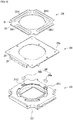
FIG. 1 is a perspective view of a lens moving apparatus according to an embodiment; -
FIG. 2 is an exploded view of the lens moving apparatus shown inFIG. 1 ; -
FIG. 3 is a view illustrating the assembled state of the lens moving apparatus shown inFIG. 1 , from which a cover is removed; -
FIG. 4A is a first perspective view of a bobbin and the first coil shown inFIG.1 ; -
FIG. 4B is a second perspective view of the bobbin and the first coil shown inFIG. 1 ; -
FIG. 5A is a first perspective view of a housing shown inFIG. 1 ; -
FIG. 5B is a second perspective view of the housing shown inFIG. 1 ; -
FIG. 6 is a cross-sectional view of the lens moving apparatus shown inFIG. 3 , which is taken along line A-B inFIG. 3 ; -
FIG. 7 is a perspective view of an upper elastic member shown inFIG. 2 ; -
FIG. 8 is an enlarged view of a first outer frame of a first upper spring shown inFIG. 7 ; -
FIG. 9 is an assembled perspective view of the upper elastic member, a lower elastic member, a third coil, a circuit board and the base, which are shown inFIG. 2 ; -
FIG. 10 is an exploded perspective view of the third coil, the circuit board, the base, first and second position sensors and an amplifier; -
FIG. 11 is a plan view ofFIG. 3 ; -
FIG. 12A is a perspective view of a first dotted area ofFIG. 11 ; -
FIG. 12B is a perspective view of a second dotted area ofFIG. 11 ; -
FIG. 13 illustrates a first extension and a damper according to another embodiment; -
FIG. 14 is a view illustrating a mutual inductance according to the distance between the first coil and the second coil; -
FIG. 15 is an exploded perspective view illustrating a camera module according to an embodiment; -
FIG. 16 is a perspective view of a portable terminal according to an embodiment; and -
FIG. 17 is a view illustrating the configuration of the portable terminal illustrated inFIG. 16 . - Hereinafter, embodiments will be clearly elucidated via description thereof with reference to the accompanying drawings. In the following description of the embodiments, it will be understood that, when an element such as a layer (film), region, pattern, or structure is referred to as being "on" or "under" another element, it can be "directly" on or under another element, or can be "indirectly" formed such that an intervening element may also be present. In addition, it will also be understood that the criteria for "on" or "under" are determined on the basis of the drawings.
- In the drawings, the dimensions of layers may be exaggerated, omitted or illustrated schematically for clarity and convenience of description. In addition, the dimensions of constituent elements may not accurately reflect the actual dimensions. Wherever possible, the same reference numbers will be used throughout the drawings to refer to the same or like parts.
- For the convenience of description, although the lens moving apparatus is described using a rectangular coordinate system (x, y, z), the lens moving apparatus may be described using some other coordinate systems, and the embodiments are not limited thereto. In the respective drawings, the X-axis and the Y-axis mean directions perpendicular to an optical axis, i.e. the Z-axis, and the optical axis (Z-axis) direction or a direction parallel to the optical axis may be referred to as a "first direction", the X-axis direction may be referred to as a "second direction", and the Y-axis direction may be referred to as a "third direction".
- A "handshake correction device", which is applied to a subminiature camera module of a mobile device such as, for example, a smart phone or a tablet PC, may be a device that is configured to prevent the contour line of a captured image from being indistinctly formed due to vibration caused by shaking of the user's hand when capturing a still image.
- In addition, an "auto-focusing device" is a device that automatically focuses an image of a subject on an image sensor surface. The handshake correction device and the auto-focusing device may be configured in various ways, and the lens moving apparatus according to an embodiment may move an optical module, which is constituted of at least one lens, in the first direction, which is parallel to the optical axis, or relative to a plane defined by the second and third directions, which are perpendicular to the first direction, thereby performing handshake correction motion and/or auto-focusing.
-
FIG. 1 is a perspective view of alens moving apparatus 100 according to an embodiment.FIG. 2 is an exploded view of thelens moving apparatus 100 shown inFIG. 1 .FIG. 3 is a view illustrating the assembled state of thelens moving apparatus 100 shown inFIG. 1 , from which acover 300 is removed. - Referring to
FIGs. 1 to 3 , thelens moving apparatus 100 may include abobbin 110, afirst coil 120,magnets 130, ahousing 140, an upperelastic member 150, a lowerelastic member 160, and asecond coil 170. - The
lens moving apparatus 100 may further include acircuit board 250. - The
lens moving apparatus 100 may further includesupport members 220. - The
lens moving apparatus 100 may further include athird coil 230 and aposition sensor 240. Thelens moving apparatus 100 may further include acover member 300 and abase 210. - The
cover member 300 will be described. - The
cover member 300 accommodates thecomponents cover member 300 and thebase 210. - The
cover member 300 may take the form of a box that has an open bottom and comprises a top plate and a side plate. The bottom of thecover member 300 may be coupled to the top of thebase 210. - The
cover member 300 may have an opening formed in the top plate thereof in order to expose a lens (not shown), coupled to thebobbin 110, to outside light. - Although the material of the
cover member 300 may be a non-magnetic material such as, for example, SUS in order to prevent thecover member 300 from being attracted by themagnets 130, thecover member 300 may be formed of a magnetic material, and may thus function as a yoke for increasing electromagnetic force caused by interaction between thecover member 300 and thefirst coil 120. - Next, the
bobbin 110 will be described. - The
bobbin 110 may allow a lens or a lens barrel to be mounted thereon and may be disposed in thehousing 140. -
FIG. 4A is a first perspective view of thebobbin 110 and thefirst coil 120 shown inFIG.1 .FIG. 4B is a second perspective view of thebobbin 110 and thefirst coil 120 shown inFIG. 1 . - Referring to
FIGs. 4A and4B , thebobbin 110 may includefirst projections 111, which project from the upper surface of thebobbin 110 in the first direction, andsecond projections 112, which project from the outer peripheral surface of thebobbin 110 in the second and/or third direction. - Each of the
first projections 111 of thebobbin 110 may include a first guide portion 111a and a first stopper 1111b. The first guide portion 111a of thebobbin 110 may serve to guide the positioning of the upperelastic member 150. For example, the first guide portion 111a of thebobbin 110 may guide a first frame-connectingportion 153 of the upperelastic member 150. - The
second projections 112 of thebobbin 110 may project from the outerperipheral surface 110b of thebobbin 110 in the second and/or third direction. In order to avoid spatial interference with the first frame-connectingportions 153, the upper surfaces of thesecond projections 112 may be positioned lower than the upper surface of thebobbin 110. For example, each of thesecond projections 112 may be an escape groove, and the escape groove may have a shape that is depressed from the upper surface of thebobbin 110. - The
bobbin 110 may includesecond stoppers 116, which project from the lower surface thereof. - The
bobbin 110 may includeside portions 110b-1, which correspond to or face themagnets 130, andside portions 110b-2 positioned between theside portions 110b-1. - The
bobbin 110 may be provided in the outer peripheral surface thereof with a first coil groove (not shown), to which thefirst coil 120 is disposed or mounted. The number and shape of first coil grooves may correspond to the number or shape of thefirst coils 120 disposed on the outerperipheral surface 110b of thebobbin 110. In another embodiment, thebobbin 110 may not have the first coil groove, and thefirst coil 120 may be directly wound around the outerperipheral surface 110b of thebobbin 110 and may be secured thereto. - Furthermore, the
bobbin 110 may be provided on the upper surface thereof withprotrusions 113, which are fitted into holes 151a in firstinner frames 151. - Each of the
protrusions 113 may include a firstupper protrusion 113a and a secondupper protrusion 113b, which are disposed on theside portion 110b-1 so as to be spaced apart from each other. - The first
upper protrusions 113a are intended to be fused to the firstinner frames 151 of the upperelastic member 150, and the secondupper protrusions 113b are intended to be conductively connected to the firstinner frames 151 of the upperelastic member 150 via solder or conductive adhesive members. For example, the diameter of the firstupper protrusion 113a may be larger than the diameter of the secondupper protrusion 113b. - The
bobbin 110 may be provided in the lower surface thereof with a firstlower coupling groove 117, which is coupled or secured to ahole 161a in the lowerelastic member 160. In another embodiment, for coupling with thehole 161a in the lowerelastic member 160, the lower surface of thebobbin 110 may be provided with a support protrusion. - The
bobbin 110 may be provided in the inner peripheral surface thereof with a threadedline 11 for engagement with a lens or a lens barrel. The threadedline 11 may be formed in the inner peripheral surface of thebobbin 110 in the state in which thebobbin 110 is held by means of a jig, and the upper surface of thebobbin 110 may have jig-holdinggrooves grooves side portions 110b-2 that are opposite each other, without being limited thereto. - Next, the
first coil 120 will be described. - The
first coil 120 may be a drive coil, which is disposed on the outerperipheral surface 110b of thebobbin 110 so as to perform electromagnetic interaction with themagnets 130 disposed on thehousing 140. - In order to create electromagnetic force through interaction with the
magnets 130, a drive signal (for example, drive current or voltage) may be applied to thefirst coil 120. - The drive signal applied to the
first coil 120 may be an AC signal, for example, AC current. For example, the drive signal applied to thefirst coil 120 may be a sinusoidal wave or a pulse signal (for example, a pulse width modulation (PWM) signal). - In another embodiment, the drive signal that is applied to the
first coil 120 may include an AC signal and a DC signal. - An AF movable unit or an AF mover may be moved in the first direction by virtue of electromagnetic force resulting from the interaction between the
first coil 120 and themagnets 130. By controlling the intensity and/or polarity of a drive signal applied to the first coil 120 (for example, the direction in which current flows) and thus controlling the intensity and/or direction of electromagnetic force resulting from the interaction between thefirst coil 120 and themagnets 130, it is possible to control the movement of the AF movable unit in the first direction, thereby performing an autofocus function. - The AF movable unit or the mover may include the
bobbin 110, which is elastically supported by the upper and lowerelastic members bobbin 110 and are moved therewith. For example, the AF movable unit may include thebobbin 110, thefirst coil 120, and a lens (not shown) mounted on thebobbin 110. - The
first coil 120 may be wound or disposed around the outer peripheral surface of thebobbin 110 in a clockwise or counterclockwise direction about the optical axis. In another embodiment, thefirst coil 120 may be embodied as a coil ring, which is wound or disposed in a clockwise or counterclockwise direction about an axis perpendicular to the optical axis. Although the number of coil rings may be equal to the number ofmagnets 130, the disclosure is not limited thereto. - The
first coil 120 may be conductively connected to at least one of the upperelastic member 150 or the lowerelastic member 160, and may be conductively connected to thecircuit board 250 via the upperelastic member 150 or the lowerelastic member 160 and thesupport members 220. For example, thefirst coil 120 may be conductively connected to third and fourth upper springs 150-3 and 150-4. - Next, the
housing 140 will be described. - The
housing 140 accommodates therein thebobbin 110, with thefirst coil 120 disposed thereon. -
FIG. 5A is a first perspective view of thehousing 140 shown inFIG. 1 .FIG. 5B is a second perspective view of thehousing 140 shown inFIG. 1 .FIG. 6 is a cross-sectional view of thelens moving apparatus 110 shown inFIG. 3 , which is taken along line A-B inFIG. 3 . - Referring to
FIGs. 5A, 5B and6 , thehousing 140 may be configured to have the overall shape of a cylinder having an opening therein, and may include a plurality ofside portions - For example, the
housing 140 may include theside portions 141, which are spaced apart from each other, and theside portions 142, which are spaced apart from each other. Each of theside portions 141 of thehousing 140 may be disposed or positioned between twoadjacent side portions 142 so as to connect the twoadjacent side portions 142 to each other, and may include a flat surface having a predetermined depth. - Since the
side portions 142 of thehousing 140 correspond to the corner regions of thehousing 140, theside portions 142 of thehousing 140 may be represented as "corner portions". - As illustrated in
FIG. 5A , for example, thehousing 140 may include first to fourth side portions and first tofourth corner portions 501a to 501d. - The first side portion and the third side portion may face each other in the second direction, and the second side portion and the fourth side portion may face each other in the third direction.
- The
first corner portion 501a may be positioned between the first side portion and the second side portion of thehousing 140, and thesecond corner portion 501b may be positioned between the second side portion and the third member of thehousing 140. Thethird corner portion 501c may be positioned between the third side portion and the fourth side portion of thehousing 140, and thefourth corner portion 501d may be positioned between the fourth side portion and the first side portion of thehousing 140. - Although the
side portion 141 of thehousing 140 may correspond to or face theside portion 110b-1 of thebobbin 110 and theside portion 142 of thehousing 140 may correspond to or face theside portion 110b-2 of thebobbin 110, the disclosure is not limited thereto. - The
magnets 130; 130-1 to 130-4 may be disposed or mounted on theside portions 141 of thehousing 140, and thesupport members 220 may be disposed on theside portions 142 of thehousing 140. - In order to support or receive the magnets 130-1 to 130-4, the
housing 140 may include magnet mounts 141a, which are provided on the inner surfaces of theside portions 141. - The
housing 140 may be provided in the outer surface thereof with afirst groove 148, in which thesecond coil 170 is wound or received. - For example, the
first groove 148 in thehousing 140 may be configured to have a shape that is depressed from the outer surfaces of theside portions 141 and the outer surfaces of theside portions 142 of thehousing 140, and may be configured to have a ring shape, without being limited thereto. - For example, the
first groove 148 in thehousing 140 may be provided in the upper ends of the outer surfaces of theside portions 141 and the upper ends of the outer surfaces of theside portions 142 of thehousing 140. - For example, the
first groove 148 in thehousing 140 may be spaced apart from the upper surface of thehousing 140, and may be provided above the magnets 130-1 to 130-4 disposed on thehousing 140. - At least one of the
side portions 141 of thehousing 140 may havegrooves - For example, the
second groove 61a may be formed in the first side portion of thehousing 140, and athird portion 17c of thesecond coil 170 may be disposed in thesecond groove 61a. The third groove 61b may be formed in the third side portion of thehousing 140, and afifth portion 17e of thesecond coil 170 may be disposed in the third groove 61b. - For example, the
groove 61 may be formed in each of the first to fourth side portions of thehousing 140. - For example, each of the
grooves side portion 141 of thehousing 140 and is open at the upper surface thereof. - Although two
grooves side portions 141 of thehousing 140 inFIG. 5A , the disclosure is not limited thereto. - Each of the
grooves first groove 148 and may be positioned above thefirst groove 148. - For example, the
second groove 61a may be disposed between aprotrusion 143b disposed on thefirst corner portion 501a and aprojection 31a disposed on the first side portion of thehousing 140 adjacent to thefirst corner portion 501a. - For example, the third groove 61b may be disposed between a protrusion 143b1 disposed on the
second corner portion 501b and aprojection 31b disposed on the third side portion of the housing adjacent to thesecond corner portion 501b. - The
grooves 61 may be positioned between aprotrusion 32b disposed on the third side portion of thehousing 140 and aprotrusion 143b disposed on thethird corner portion 501c and between aprotrusion 32a disposed on the first side portion of thehousing 140 and aprotrusion 143a disposed on thefourth corner portion 501d. - For example, the
grooves first groove 148, in which afirst portion 17a of thesecond coil 170 is disposed, and may be provided at the lower ends thereof with openings communicating with thefirst groove 148. - The first and
second grooves 61a and 61b in thehousing 140 may serve as paths through which a portion or another portion of thesecond coil 170 extends, and thegrooves housing 140 may serve as injection ports through which adhesive for attaching themagnets 130 to thehousing 140 is injected. - The
housing 140 may include guideprojections 65 disposed on the inner surface thereof so as to guide the adhesive injected into thegrooves guide projections 65 may serve to block the introduction of the adhesive into thehousing 140. - The
side portions 141 of thehousing 140 may be disposed parallel to the side plate of thecover member 300. Theside portions 142 of thehousing 140 may be provided withholes 147a through which thesupport members 220 extend. Each of theholes 147a may be configured such that the diameter thereof is gradually increased moving toward the lower surface from the upper surface of thehousing 140. The reason for this is to allow a damper, which will be described later, to be easily disposed in thehole 147a. - Furthermore, the
housing 140 may be provided on the upper surface thereof withsecond stoppers 144 so as to prevent thehousing 140 from directly colliding with the inner surface of thecover member 300. For example, although thesecond stoppers 144 may be respectively disposed on the first tofourth corner portions 501a to 501d of thehousing 140, the disclosure is not limited thereto. - In order to guide positioning of first
outer frames 152 of the upperelastic member 150 when the upperelastic member 150 is placed on the upper surface of thehousing 140, thehousing 140 may be provided on the upper surface thereof withsecond guide portions 146. - The
second guide portions 146 may be disposed on thecorner portions 501a to 501d of thehousing 140 so as to be respectively spaced apart from thesecond stoppers 144. For example, each of thesecond guide portions 146 may face a corresponding one of thesecond stoppers 144 in a diagonal direction. Here the diagonal direction may be the direction toward thesecond stopper 144 from the center of thehousing 140. Furthermore, thesecond guide portions 146 may also serve as stoppers for preventing the upper surface of thehousing 140 from directly colliding with the inner surface of thecover member 300. - The
housing 140 may include one or morefirst protrusions side portions 142 for coupling into holes 152a1 and 152a2 in the firstouter frame 152 of the upperelastic member 150. - The
first protrusions fourth corner portions 501a to 501d of thehousing 140. - For example, the
housing 140 may includefirst protrusions 143a and 143a1, which are disposed at one side of thesecond guide portion 146, andfirst protrusions 143b and 143b1, which are disposed at the other side of thesecond guide portion 146. - For example, although the
first protrusions first protrusions - Furthermore, the
housing 140 may include one or moresecond protrusions side portions 142 for coupling with theholes 26 in the firstouter frames 152 of the upperelastic member 150. - For example, although the
second protrusions side portions 141 that face each other, among theside portions 141 of thehousing 140, the disclosure is not limited thereto. - For example, the
second protrusion 32a may be positioned at the upper surface of one of theside portions 141, for example, thefirst side portion 141 of thehousing 140 adjacent to thefirst corner portion 501a. Thesecond protrusion 32b may be positioned at the upper surface of another one of theside portions 141, for example, the third side portion of thehousing 140 adjacent to thesecond corner portion 501b. - For example, the
second protrusions side portions 141 of thehousing 140 that face each other in the second or third direction. - Furthermore, the
housing 140 may includeprojections side portions 141 of thehousing 140 so as to stably hold a portion (for example, a starting portion) and another portion (for example, an ending portion) of thesecond coil 170. - The
projections side portions 141 of thehousing 140, for example, on the upper surfaces of the first side portion and the third side portion of thehousing 140. Theprojections housing 140, at which thesecond protrusions - For example, the
first projection 31a may be disposed between thefirst protrusion 143b disposed on thefirst corner portion 501a and thesecond protrusion 32a disposed on the upper surface of the first side portion of thehousing 140 adjacent to thefirst corner portion 501a. - The
second projection 31b may be disposed between the first protrusion 143b1 disposed on thecorner portion 501b and thesecond protrusion 32b disposed on the upper surface of the third side portion of thehousing 140 adjacent to thesecond corner portion 501b. - The
first groove 61a may be positioned between thefirst protrusion 143b disposed on thefirst corner portion 501a and thefirst projection 31a disposed on the first side portion of thehousing 140 adjacent to thefirst corner portion 501a, and the second groove 61b may be positioned between the second protrusion 143b1 disposed on thesecond corner portion 501b of thehousing 140 and thesecond projection 31b disposed on the third side portion of thehousing 140 adjacent to thesecond corner portion 501b. - Since the first and
second grooves 61a and 61b are respectively positioned adjacent to the first andsecond projections second coil 170 may be easily wound around the first andsecond projections - The
housing 140 may include one ormore protrusions 145 disposed on the lower surfaces of the side portions of thehousing 140 so as to be coupled or secured toholes 162a in secondouter frames 162 of the lowerelastic member 160. Although theprotrusions 145 may be disposed on at least one of the first tofourth corner portions 501a to 501d of thehousing 140, the disclosure is not limited thereto. - In order to ensure not only paths through which the
support members 220 extend but also spaces that are filled with silicone for damping, thehousing 140 may haverecesses 142a formed in the lower portions of theside portions 142. Therecesses 142a in thehousing 140 may be filled with, for example, damping silicone. - The
housing 140 may havethird stoppers 149, which project from the outer surfaces of theside portions 141 in the second or third direction. Although thehousing 140 is illustrated inFIG. 5A as having twothird stoppers side portions 141, the disclosure is not limited thereto. - The
third stoppers 149 are intended to prevent thehousing 140 from colliding with the inner surfaces of the side portions of thecover member 300 when thehousing 140 moves in the second and third directions. - In order to prevent the bottom surface of the
housing 140 from colliding with thebase 210, thethird coil 230 and/or thecircuit board 250, which will be described later, thehousing 140 may further include a fourth stopper (not shown) projecting from the lower surface thereof. - Next, the
magnets 130; 130-1 to 130-4 will be described. - Although the magnets 130-1 to 130-4 are disposed in the
side portions 141 of thehousing 140, the disclosure is not limited thereto. In another embodiment, the magnets 130-1 to 130-4 may be disposed outside theside portions 141 of thehousing 140. - The
magnets 130 may be disposed on theside portions 141 of thehousing 140 so as to correspond to or be aligned with thefirst coil 120 in a direction perpendicular to the optical axis at the initial position of thebobbin 110. - For example, the magnets 130-1 to 130-4 disposed on the
housing 130 may overlap thefirst coil 120 in the second or third direction at the initial position of thebobbin 110. - Here, the initial position of the
bobbin 110 may be the initial position of the AF movable unit in the state in which power is not applied to thefirst coil 120, and may be the position of the AF movable unit when the upperelastic member 150 and the lowerelastic member 160 are elastically deformed by only the weight of AF movable unit. - Furthermore, the initial position of the
bobbin 110 may be the position of the AF movable unit when gravity is applied toward the base 210 from thebobbin 110 or toward thebobbin 110 from thebase 210. The AF movable unit may include thebobbin 110 and components mounted on thebobbin 110, for example, thefirst coil 120. - In another embodiment, the magnet mounts 141a may not be provided in the side portions of the
housing 140, and themagnets 130 may be disposed inside or outside the side portions of thehousing 140. - Although each of the
magnets 130 may have a shape that corresponds to a corresponding one of the side portions of thehousing 140, for example, a rectangular parallelepiped shape, the disclosure is not limited thereto. - Although each of the
magnets 130 may be a monopole-magnetized magnet which is constructed such that a surface thereof that faces thefirst coil 120 is an S pole and the opposite second surface thereof is an N pole or a bipole-magnetized magnet, the disclosure is not limited thereto, and the reverse disposition is also possible. - Although the number of
magnets 130 is four in the embodiment, the disclosure is not limited thereto, and the number ofmagnets 130 may be at least two. Although each of the surfaces of themagnets 130 that faces thecoil 120, may be a flat surface, the disclosure is not limited thereto, and the surface may be a curved surface. - Next, the upper
elastic member 150 and the lowerelastic member 160 will be described. - Each of the upper
elastic member 150 and the lowerelastic member 160 is coupled both to thebobbin 110 and to thehousing 140 so as to elastically support thebobbin 110. In the upperelastic member 150 and/or the lowerelastic member 160, the term "elastic member" may be replaced with the term "elastic unit". - For example, the upper
elastic member 150 may be coupled both to the upper portion, the upper surface or the upper end of thebobbin 110 and to the upper portion, the upper surface or the upper end of thehousing 140, and the lowerelastic member 160 may be coupled both to the lower portion, the lower surface or the lower end of thebobbin 110 and to the lower portion, the lower surface or the lower end of thehousing 140. -
FIG. 7 is a perspective view of the upperelastic member 150 shown inFIG. 2 .FIG. 8 is an enlarged view of a firstouter frame 152 of a first upper spring 150-1 shown inFIG. 7 .FIG. 9 is an assembled perspective view of the upperelastic member 150, the lowerelastic member 160, thethird coil 230, thecircuit board 250 and thebase 210, which are shown inFIG. 2 .FIG. 10 is an exploded perspective view of thethird coil 230, thecircuit board 250, thebase 210, first andsecond position sensors - Referring to
FIGs. 7 to 10 , at least one of the upper and lowerelastic members - For example, the upper
elastic member 150 may include first to fourth upper springs 150-1 to 150-4, which are spaced apart from one another. Here, the term "upper spring" may be replaced with the term "spring". - Although each of the upper
elastic member 150 and the lowerelastic member 160 may be embodied as a leaf spring, the disclosure is not limited thereto. Each of the upper and lowerelastic members - Each of the first to fourth upper springs 150-1 to 150-4 may include a first
inner frame 151 coupled to the upper portion, the upper surface or the upper end of thebobbin 110, a firstouter frame 152 coupled to the upper portion, the upper surface or the upper end of thehousing 140, and a first frame-connectingportion 153 connecting the firstinner frame 151 to the firstouter frame 152. - The first frame-connecting
portion 153 may connect the firstouter frame 152, for example, a third coupling portion 510-2, to the inner frame. - Each of the first and second frame-connecting
portions elastic members bobbin 110 in the first direction may be elastically (flexibly) supported through positional variation and fine deformation of the first and second frame-connectingportions - The first
outer frame 152 of each of the first to fourth upper springs 150-1 to 150-4 may include an outer portion 510 coupled to thehousing 140, afirst coupling portion 520 coupled to a corresponding one of the support members 220-1 to 220-4, and a first connectingportion 530 connectingouter portions 510a to 510d to thefirst coupling portion 520. - The
first coupling portion 520 may include afirst extension 540, which extends toward theouter portions 510a to 510d from thefirst coupling portion 520. - Each of the
outer portions 510a to 510d may be disposed on the corner portion and at least oneside portion 141 of thehousing 140 adjacent to the corner portion. - For example, each of the
outer portions 510a to 510d may be coupled to the corner portion of thehousing 140 and to at least one side portion of thehousing 140 adjacent to the corner portion or the other side portion of thehousing 140 adjacent to the corner portion. - For example, the first
outer portion 510a may include a second coupling portion 510-a, which is disposed on the first side portion of thehousing 140 and is coupled to thehousing 140, a third coupling portion 510-2, which is disposed on the second side portion adjacent to the first side portion of thehousing 140 and is coupled to thehousing 140, and a second connecting portion 510-3 connecting the second coupling portion 510-1 to the third coupling portion 510-2. - At least one first outer frame of the first to fourth upper springs 150-1 to 150-4 may include an outer portion, which is not disposed on the corner portion but is disposed on the side portion of the
housing 140, a first coupling portion and a connecting portion connecting the first coupling portion to the outer portion. Here, the outer portion may not be coupled to the corner portion of the housing, but may be coupled to the side portion of the housing adjacent to the corner portion. - The first connecting
portion 530 may include a third connectingportion 530a connecting the second coupling portion 510-1 to thefirst coupling portion 520, and a fourth connectingportion 530b connecting the third coupling portion 510-2 to thefirst coupling portion 520. - The
first extension 540 may be spaced apart from theouter portion 510a. Thefirst extension 540 may include a portion, which is increased in width moving toward theouter portion 510a from thefirst coupling portion 520. For example, thefirst extension 540 may include a portion, which is increased in width moving toward the center of the upper springs 150-1 to 150-4 from thefirst coupling portion 520. - For example, the portion of the
first extension 540 that is increased in width may be configured to have a sector shape. The central angle (θ, seeFIG. 13 ) of the sector-shapedfirst extension 540 about acoupling region 520a may be in the range of 40 - 160 degrees. If the central angle (θ, seeFIG. 13 ) of thefirst extension 540 is smaller than 40 degrees, an effect of improving solderability may be decreased. Meanwhile, if the central angle of thefirst extension 540 is larger than 160 degrees, there may be spatial interference with the first connectingportion 530. - The portion of the
first extension 540 that corresponds to theouter portion 510a may have a shape corresponding to the shape of theouter portion 510a. - The
first extension 540 may be spaced apart both from the third connectingportion 530a and from the fourth connectingportion 530b. - The
first extension 540 may include a second extension, which extends to the second coupling portion 510-1 from thefirst coupling portion 520, a third extension, which extends to the third coupling portion 510-2 from thefirst coupling portion 520, and a fourth extension, which extends to the second connecting portion 510-3 from thefirst coupling portion 520. - A damping
member 91 may connect thefirst extension 540 to theouter portion 510a. The dampingmember 91 may be disposed between thefirst extension 540 and the second connecting portion 510-3. - The second coupling portion 510-1 may have therein a hole 152a2, which is coupled to the
second protrusion 143b of thehousing 140, and the third coupling portion 510-2 may have therein a hole 152a1, which is coupled to thesecond protrusion 143a of thehousing 140. - The second coupling portion 510-1 may be positioned at one side of a reference line (for example, 501), and the third coupling portion 510-2 may be positioned at the other side of the reference line (for example, 501).
- Although each of the second coupling portion 510-1 and the third coupling portion 510-2 is embodied as having through holes 152a1, 152a2, 25 and 26 in the embodiment shown in
FIGs. 7 and8 , the disclosure is not limited thereto. In another embodiment, the second and third coupling portions may also be embodied as having various shapes suitable for being coupled to thehousing 140, for example, grooves or the like. - Each of the holes 152a1 and 152a2 may have at least one
slit 21a for allowing an adhesive member to be introduced into the clearance between theprotrusions - The second coupling portion 510-1 may include the holes 152a2 and 26, which are positioned at the
first corner portion 501a and a first side portion of the housing adjacent to thefirst corner portion 501a, and agroove 81, which is positioned between the holes 152a2 and 26. - The second coupling portion 510-1 may include a first zone S1, which is disposed on the
first corner portion 501a and in which the hole 152a2 is positioned, and a second zone S2, which is connected to the first zone S1 and which extends to the upper surface of the first side portion of thehousing 140 adjacent to thefirst corner portion 501a and is disposed thereon. - The second coupling portion 510-1 may include a first zone S1, which is disposed on the
first corner portion 501a and in which the hole 152a2 is positioned, and a second zone S2, which is connected to the first zone S1 and which extends to the upper surface of the first side portion of thehousing 140 adjacent to thefirst corner portion 501a and is disposed thereon. - In another embodiment, the second coupling portion may be disposed at at least one of the first corner portion and one side portion of the
housing 140 adjacent to the first corner portion, and may be coupled to at least one of the first corner portion and one side portion of thehousing 140 adjacent to the first corner portion. - The second zone S2 may be provided with the
groove 81, in which theprojection 31a of thehousing 140 is fitted, and one end of the second zone S2 may be provided with thehole 26, to which thesecond projection 32a of thehousing 140 is coupled. - The
first protrusion 143b of thefirst corner portion 501a of thehousing 140 and the hole 152a2 in the second coupling portion 510-1 may be fused to each other, and thesecond protrusion 32a of thehousing 140 and thehole 26 in the second coupling portion 510-1 may be fused to each other. The fusion coupling may mean that thesecond protrusion 32a is bonded to the upper spring by heat. - Since the
protrusions first projection 31a of thehousing 140 is fused to the outer portion of the first upper spring 150-1 of the upper spring 150-1, the embodiment is able to stably secure the firstouter portion 510a of the first upper spring 150-1 to thehousing 140 and to stably couple one end of thesecond coil 170 to the firstouter portion 510a of the first upper spring 150-1. Accordingly, the embodiment is able to prevent disconnection of or damage to thesecond coil 170 caused by external impact. - The third coupling portion 510-2 may have one or more holes 152a1 and 25, which are positioned at at least one of the
first corner portion 501a and the other side portion of thehousing 140 adjacent to thefirst corner 501a. - The third coupling portion 510-2 may include a third zone S3, which is disposed on the
first corner portion 501a and in which the hole 152a1 is disposed, and a fourth zone S4, which is connected to the third zone S3 and which extends to the upper surface of the other side portion of thehousing 140 adjacent to thefirst corner portion 501a and is disposed thereon. - One end of the fourth zone S4 may be provided with the
hole 25 so as to be coupled to thehousing 140 via an adhesive member. Although thehole 25 has a crisscross shape inFIG. 8 , the disclosure is not limited to that shape, and the hole may have, for example, a circular shape, an elliptical shape or a polygonal shape. - In another embodiment, the third coupling portion may be disposed on at least one of the first corner portion and the other side portion of the
housing 140 adjacent to the first corner portion, and may be coupled to at least one of the first corner portion and the other side portion of thehousing 140 adjacent to the first corner portion. - The second connecting portion 510-3 may connect the second coupling portion 510-1 to the third coupling portion 510-2.
- For example, the second connecting portion 510-3 may connect the first zone S1 of the second coupling portion 510-1 to the third zone S3 of the third coupling portion 150-2, and the mounting position of the second connecting portion 510-3 may be guided by the
second guide 146 of thehousing 140. - Although the second connecting portion 510-3 may be configured to be convex toward the
first corner portion 501a of thehousing 140 from acentral point 101, the disclosure is not limited thereto. The second connecting portion 510-3 may be configured to be convex the central point of thehousing 140 from thecorner portion 501b of thehousing 140. - The
first coupling portion 520 may have ahole 52 through which thesupport member 220 extends. One end of thesupport member 220 that has passed through thehole 52 may be coupled to thefirst coupling portion 520 via a conductive adhesive member or a solder 910, and thefirst coupling portion 520 may be conductively connected to thesupport member 220. - The
first coupling portion 520 may include acoupling region 520a, which is coupled to thesupport member 220 via thesolder 901, and thecoupling region 520a may include thehole 52 and a region around thehole 520 on which the solder is disposed. - The first connecting
portion 530 may connect at least one of the second coupling portion 510-1 and the third coupling portion 510-2 to thefirst coupling portion 520. - For example, the first connecting
portion 530 may include the third connectingportion 530a, connecting the first zone S1 of the second coupling portion 510-1 to thefirst coupling portion 520, and the fourth connectingportion 530b, connecting the third zone S3 of the third coupling portion 510-2 to thefirst coupling portion 520. - Although each of the third connecting
portion 530a and the fourth connectingportion 530b may include a bent portion, which is bent at least once, or a curved portion, which is curved at least once, the disclosure is not limited thereto. In another embodiment, the third connectingportion 530a and the fourth connectingportion 530b may be linear. - The width W31 of the third connecting
portion 530a or the fourth connectingportion 530b of the first connectingportion 530, which is bent at least once, may be smaller than a first width W11 or W12 of the second coupling portion 510-1, a second width W21 or W22 of the third coupling portion 510-2 or a third width W1 of the second connecting portion 510-3. - For example, the first width W11 or W12 may be the minimal width along the entire region of the second coupling portion 510-1, the second width W21 or W22 may be the minimal width along the entire region of the third coupling portion 510-2, and the third width W3 may be the minimal width along the entire region of the second connecting portion 510-13.
- Since the relationships between the widths are W31<W12, W31<W22 and <W31<W3, the first connecting
portion 530 may be easily movable in the first direction, whereby it is possible to distribute the stress applied to the upperelastic member 150 and the stress applied to thesupport member 220. - The
first extension 540 may extend by a predetermined length L1 in a direction toward theouter portion 510a from thecoupling region 520a of the first coupling portion 520 (hereinafter, referred to as an "extension direction"). - The predetermined length L1 may be, for example, 0.1 mm - 2 mm. If the length L1 is smaller than 0.1 mm, the effect of heat radiation and solderability may be deteriorated due to the decreased surface area of the
first extension 540. Meanwhile, if the length L1 is greater than 2 mm, there may be spatial interference with the first connectingportion 530 and the outer portion. - In order to sufficiently ensure improvement of solderability and elimination of interference with the first connecting
portion 530 and the outer portion, the length L1 may be within a range of 0.2 mm - 1.2 mm. - For example, the extension direction may be a direction toward at least one of the second coupling portion 510-1, the third coupling portion 510-2 and the second connecting portion 510-3 of the
outer portion 510a from thecoupling region 520a of thefirst coupling portion 520. - The length L1 of the
first coupling portion 520 may be larger than the length L2 of thecoupling 520. The length L1 may be a distance between thecoupling region 520a and one end of thefirst coupling portion 520 that extends in the extension direction of thefirst extension 540. The second length L2 may be a distance between thecoupling region 520a and the other end of thefirst coupling portion 520 that extends in a direction opposite the extension direction of thefirst extension 540. - The length L1 of the
first extension 540 may be larger than the distance L2 between thecoupling region 520a of thefirst coupling portion 520 and the end of thefirst coupling portion 520 in a direction opposite the extension direction (L1>L2). - The area of the upper surface of the
first extension 540 may be larger than the area of the upper surface of thefirst coupling portion 520. - The
first extension 540 may serve to increase the surface area through which heat is transmitted to thefirst coupling portion 520 and to improve solderability when thefirst coupling portion 520 is soldered to thesupport member 220. - The
first extension 540 may be spaced apart from theouter portion 510a and the first connectingportion 530. - For example, the
first extension 540 may be spaced apart from the first zone S1 of the second coupling portion 510-1, the third zone S3 of the third coupling portion 510-2, the second connecting portion 510-3, the third connectingportion 530a and the fourth connectingportion 530b. - Although the distance between the
first extension 540 and the second connecting portion 510-3 may be smaller than the distance between thefirst extension 540 and the first zone S1 of the second coupling portion 510-1 and the distance between thefirst extension 540 and the third zone S3 of the third coupling portion 510-2, the disclosure is not limited thereto. - The distance between the
first extension 540 and the second connecting portion 510-3 may be, for example, within a range of 0.03 mm - 0.2 mm. If the distance between thefirst extension 540 and the second connecting portion 510-3 is smaller than 0.03 mm, there may be spatial interference between thefirst extension 540 and the second connecting portion 510-3. Meanwhile, if the distance thefirst extension 540 and the second connecting portion 510-3 is larger than 0.2 mm, the distance may be increased, thereby making it difficult to form a damper between thefirst extension 540 and the second connecting portion 510-3. - In order to sufficiently ensure elimination of spatial interference and easy formation of a damper, the distance between the
first extension 540 and the second connecting portion 510-3 may be within a range of 0.06 mm - 0.15 mm. - Although the
first extension 540 may be configured such that the width thereof is increased in the extension direction in order to increase a heat transmission area, the disclosure is not limited thereto. Thefirst extension 540 may be embodied so as to have various shapes. - For example, although the
first extension 540 may be configured to have at least one first vertex M1, which is positioned at the left side of thereference line 501, and at least one second vertex M2, which is positioned at the right side of thereference line 501, the disclosure is not limited thereto. - Although the outer portion 510 may be bilaterally symmetrical with respect to the reference line in order to support the
housing 140 in the balanced state without eccentricity, the disclosure is not limited thereto. In another embodiment, the outer portion may not be bilaterally symmetrical. - For example, although the second and third coupling portions and the second connecting portions 510-1 to 510-3 may be bilaterally symmetrical with respect to the reference line (for example, 501), the disclosure is not limited thereto.
- Although the
first coupling portion 520 may be bilaterally symmetrical with respect to the reference line in order to support thehousing 140 in the balanced state without eccentricity, the disclosure is not limited thereto. In another embodiment, the outer portion may not be bilaterally symmetrical. - Although the first connecting
portion 530 may be bilaterally symmetrical with respect to the reference line in order to support thehousing 140 in the balanced state without eccentricity, the disclosure is not limited thereto. In another embodiment, the outer portion may not be bilaterally symmetrical. - Although the
first extension 540 may be bilaterally symmetrical with respect to the reference line in order to support thehousing 140 in the balanced state without eccentricity, the disclosure is not limited thereto. In another embodiment, the outer portion may not be bilaterally symmetrical. - The
reference lines 501 to 504 may be lines, which extend the central point 101 (seeFIG. 7 ) and corresponding ones of the vertices (or corners) of thecorner portions 501a to 501d of thehousing 140. - Here, the
central point 101 may be the center of the housing or the center of the upper springs 150-1 to 150-4z. - The first frame-connecting
portions 153 of the first to fourth upper springs 150-1 to 150-4 may be rotationally symmetrical (for example, rotation of 90°) about the central point 101 (seeFIG. 7 ). - Each of the second to fourth upper springs 150-2 to 150-3 may be configured to have a shape identical or similar to the first upper spring. For example, the description of the first upper spring 150-1 shown in
FIG. 8 may be applied to each of the second to fourth upper springs 150-2 to 150-3. - Each of the second to fourth outer portions 510 to 510d of the second to fourth upper springs 150-2 to 150-4 may be a first coupling portion, a second coupling portion, a third coupling portion and a second connecting portion.
- The shape of the first coupling portions of the second to fourth
outer portions 510b to 510d may be identical to the shape of thefirst coupling portion 520 of the first upper spring 150-1, and the description of the first upper spring may be applied to the second to fourth outer portions. In other words, the description of the first coupling portion of the firstouter portion 510a may be applied to the first coupling portion of each of the second to fourthouter portions 510b to 510d. - The shape of at least one second or third coupling portion of the second to fourth
outer portions 510b to 510d may be different from the shape of the second or third coupling portion of the first outer portion. - The second coupling portion of the second
outer portion 510b may include the first zone having a hole 152a2, which is disposed in one region of thesecond corner portion 501b and which is coupled to the first protrusion 143a1 of thesecond corner portion 501b. The second coupling portion of the secondouter portion 510b may not include a zone corresponding to the second zone S2 of the second coupling portion 510-1 of the firstouter portion 510a. Alternatively, although the second coupling portion of the secondouter portion 510b may include a zone corresponding to the second zone of the second coupling portion 510-1 of the firstouter portion 510a, the length of the zone may be smaller than the length of the second zone. - The coupling portion of the second
outer portion 510b may include a third zone having a hole 152a1, which is formed in the other region of thesecond corner portion 501b and which is coupled to the first protrusion 143b1 of thesecond corner portion 501b, and a fourth zone, which is connected to the third zone and which extends to the upper surface of the third member of thehousing 140 adjacent to thesecond corner portion 501b. - The fourth zone of the second
outer portion 510b may be provided with thegroove 81 in which theprojection 31b of thehousing 140 is disposed, and one end of the fourth zone may be provided with thehole 26 to which thesecond protrusion 32b of thehousing 140 is coupled. - For example, the
first protrusion 143b of thesecond corner portion 501b of thehousing 140 may be fused to the hole 152a1 in the second coupling portion of the secondouter portion 510b, and theprotrusion 32b of thehousing 140 may be fused to thehole 26 in the second coupling portion of the secondouter portion 510b. - Since the protrusions 143b1 and 32b, which are positioned at both sides of the
second protrusion 31b of thehousing 140, are fused to the secondouter portion 510b of the second upper spring 150-2, the embodiment is able to stably secure the secondouter portion 510b of the second upper spring 150-2 to thehousing 140 and to stably couple the other end of thesecond coil 170 to the secondouter portion 510b of the second upper spring 150-2. Accordingly, the embodiment is able to prevent disconnection of or damage to thesecond coil 170 caused by external impact. - The second coupling portion of the third
outer portion 510c may include the first zone, which is disposed at one region of thethird corner portion 501 and which has a hole coupled to the first protrusion of thethird corner portion 501c. The second coupling portion of the thirdouter portion 510c may not include a zone corresponding to the second zone S2 of the second coupling portion 510-1 of the firstouter portion 510a. Alternatively, although the second coupling portion of the thirdouter portion 510c may include a zone corresponding to the second zone S2 of the second coupling portion 510-1 of the firstouter portion 510a, the zone may have a smaller length. - The third coupling portion of the third
outer portion 510c may be the same as the third coupling portion 510-2 of the firstouter portion 510a, and the description of the third coupling portion 510-2 of the firstouter portion 510a may be applied to the third coupling portion of the thirdouter portion 510c. - The second coupling portion of the fourth
outer portion 510d may include the first zone, which is disposed at one region of thefourth corner portion 501d and which has a hole 152a2 coupled to thefirst protrusion 143b of thefourth corner portion 501d, and the second zone, which is connected to the first zone and which extends to the upper surface of the fourth side portion of thehousing 140 adjacent to thefourth corner portion 501d. - The third coupling portion of the fourth
outer portion 510d may include the third zone, which is disposed at the other region of thefourth corner portion 510d and which is coupled to thefirst protrusion 143a of thefourth corner portion 501d. The third coupling portion of the fourthouter portion 510d may not include a zone corresponding to the fourth zone of the firstouter portion 510a. Alternatively, although the third coupling portion of the fourthouter portion 510d may include a zone corresponding to the fourth zone of the third coupling portion 510-2 of the firstouter portion 510a, the zone may have a smaller length. - The description of the second connecting portion of the first
outer portion 501a may be applied to the second connecting portion of each of the second to fourthouter portions 501b to 510d). - Although the shape of the first
outer portion 510a is partially different from the shapes of the second to fourthouter portions 510b to 510d inFIG. 7 , the disclosure is not limited thereto. In another embodiment, the shape of each of the first to fourth outer portions may be configured to be the same as the shape of the firstouter portion 510a shown inFIG. 7 . - In a further embodiment, the shape of at least one of the first to fourth outer portions of the upper
elastic member 150 may be the same as the shape of at least one of the second to fourthouter portions 501b to 510d, or may be embodied as combinations of the shapes of the second to fourthouter portions 510b to 510d. - The lower
elastic member 160 may include a secondinner frame 161 coupled to the lower portion, the lower surface or the lower end of thebobbin 110, a secondouter frame 162 coupled to the lower portion, the lower surface or the lower end of thehousing 140, and a second frame-connectingportion 163 connecting the secondinner frame 161 to the secondouter frame 162. - The lower
elastic member 160 may have therein thehole 161a, which is formed in the secondinner frame 161 and which is coupled to the firstlower coupling groove 117 in thebobbin 110 via a solder or a conductive adhesive member, and thehole 162a, which is formed in the secondouter frame 162 and which is coupled to the second protrusion 147 of thehousing 140. - Each of the first and second frame-connecting
portions elastic members bobbin 110 in the first direction may be elastically (or flexibly) supported by virtue of positional variation and fine deformation of the first and second frame-connectingportions - The
lens moving apparatus 100 may further include the damping member or damper 91 (seeFIG. 12A ), which is disposed between the second connecting portions 510-3 of the upper springs 150-1 to 150-4 and thefirst extension 540. Thedamper 91 may serve to absorb or buffer vibrations of thesupport members 220 or to buffer movement of thesupport members 220. - For example, although the
damper 91 may be brought into contact with the second connecting portion 510-3 and thefirst extension 540 and may be spaced apart from the second coupling portion 510-1 and the third coupling portion 510-2, the disclosure is not limited thereto. - For example, the
damper 91 may be disposed between the side surface of the second connecting portion 510-3 and the side surface of thefirst extension 540. Furthermore, thedamper 91 may also be disposed on the upper surface and/or the lower surface of the second connecting portion 510-3, and may also be disposed between the upper surface and/or the lower surface of thefirst extension 540. - Although the
damper 91 may be spaced apart from thecorner portions 501a to 501d of thehousing 140, the disclosure is not limited thereto. In another embodiment, thedamper 91 may also be brought into contact with thecorner portions 501a to 501d of thehousing 140. -
FIG. 13 illustrates afirst extension 540a and adamper 92 according to another embodiment. - Referring to
FIG. 13 , although thefirst extension 540 shown inFIG. 8 extends from thefirst coupling portion 520 to the second connecting portion 510-3, thefirst extension 540a shown inFIG. 13 may include a second extension 540-1 extending from thefirst coupling portion 520 to the second coupling portion 510-1, a third extension 540-2 extending from thefirst coupling portion 520 to the third coupling portion 510-2, and a fourth extension 540-3 extending from thefirst coupling portion 520 to the second connecting portion 510-3 so as to connect the second extension 540-1 to the third extension 540-2. - The
first extension 540a shown inFIG. 13 may further increase the surface area through which heat is transmitted to thefirst coupling portion 520, and may further improve solderability when thefirst coupling portion 520 is soldered to thesupport member 220. - In the embodiment shown in
FIG. 8 , the first distance between the second connecting portion 510-3 and thefirst extension 540 is smaller than the second distance between the second coupling portion 510-1 and thefirst extension 540 or the third distance between the third coupling portion 510-2 and thefirst extension 540. - In contrast, in the embodiment shown in
FIG. 13 , the first distance D1 between the second connecting portion 510-3 and thefirst extension 540a may be equal to the second distance D2 between the second coupling portion 510-1 and thefirst extension 540a and the third distance D3 between the third coupling portion 510-2 and thefirst extension 540a (D1=D2=D3). Consequently, the embodiment is able to increase the heat transmission area of thefirst extension 540a, for example, the area of the upper and lower surfaces of thefirst extension 540a, and to improve the solderability thereof. - For example, D1, D2 and D3 may be within a range of 0.03 mm - 0.2 mm.
- In order to ensure elimination of spatial interference between the
first extension 540a and the coupling portions and easy formation of the damper, D1, D2 and D3 may be within a range of 0.06 mm - 0.15 mm. - The
lens moving apparatus 100 may further include the damping member ordamper 92, which is disposed in at least one of the space between the second coupling portion 510-1 and the second extension 540-1, the space between the third coupling portion 510-2 and the third extension 540-2, and the space between the second connecting portion 510-3 and the fourth extension 540-3. The damping member ordamper 92 may serve to absorb or buffer vibrations of thesupport members 220 or may serve to buffer movement of thesupport members 220. - For example, the damping member or
damper 92 may be disposed between the side surfaces of the second and third coupling portions 510-1 and 510-2 and the side surfaces of thefirst extension 540a and between the side surface of the second connecting portion 510-3 and the side surface of thefirst extension 540a, and may be brought into contact with the side surfaces of the second and third coupling portions 510-1 and 510-3, the side surface of the second connecting portion 510-3 and the side surface of thefirst extension 540a. - For example, the damping member or
damper 92 may be disposed on the upper surface and/or the lower surface of at least one of the second and third coupling portions 510-1 and 510-2 and the second connecting portion 510-3, and may also be disposed on the upper surface and/or the lower surface of thefirst extension 540a. - In another embodiment, the damping member may be disposed only between the second connecting portion 510-3 and the
first extension 540a. Here, although D1 may be smaller than D2 and D3, the disclosure is not limited thereto. D1 may be larger than D2 and D3. - Although the damping member or
damper 92 may be spaced apart from thecorner portions 501a to 501d of thehousing 140, the disclosure is not limited thereto. In another embodiment, the damping member ordamper 92 may be brought into contact with thecorner portions 501a to 501d of thehousing 140. - In order to absorb or buffer vibrations of the
bobbin 110, thelens moving apparatus 100 may further include first damping members (not shown), each of which is disposed between a corresponding one of the upper elastic members 150-1 to 150-4 and thehousing 140. - For example, each of the first damping members (not shown) may be disposed in the space between the first frame-connecting
portion 153 of a corresponding one of the upper springs 150-1 to 150-4 and thehousing 140. - The
lens moving apparatus 100 may further include second damping members (not shown), each of which is disposed between a corresponding one of the second frame-connectingportions 163 of the lowerelastic members 160 and thehousing 140. - The
lens moving apparatus 100 may further include third damping members disposed between thesupport members 220 and theholes 147a in thehousing 140. - Furthermore, the
lens moving apparatus 100 may further include fourth damping members, which are disposed at thefirst coupling portions 520 and the first ends of thesupport members 220, and may further include fifth damping members, which are disposed at the other ends of thesupport members 220 and thecircuit board 250. - For example, a damping member (not shown) may also be disposed between the inner surface of the
housing 140 and the outer peripheral surface of thebobbin 110. - Next, the
second coil 170 will be described. - The
second coil 170 is disposed on the outer surface of thehousing 140. - For example, the
second coil 170 may be disposed on upper sides of the outer surfaces of theside portions housing 140. - The
second coil 170 may be a ring-shaped coil, which is wound about the optical axis in a clockwise or counterclockwise direction. For example, thesecond coil 170 may be a ring-shaped coil, which is wound around the outer surfaces of the first andsecond side portions housing 140 about the optical axis in a clockwise or counterclockwise direction so as to surround the outer surfaces. - The
second coil 170 may be positioned below the upperelastic member 150 but above themagnets 130. - The
second coil 170 may not overlap themagnets 130 in a direction perpendicular to the optical direction when the AF movable unit (for example, the bobbin 110) is disposed at the initial position. The reason for this is to reduce the interference between themagnets 130 and thesensing coil 170. - The
second coil 170 may be spaced apart from thefirst coil 120 by a predetermined distance in the optical direction, and may not overlap thefirst coil 120 in a direction perpendicular to the optical direction when the AF movable unit (for example, the bobbin 110) is disposed at the initial position. Maintaining the predetermined distance between thefirst coil 120 and thesecond coil 170 in the optical direction is to ensure the linearity of the induction voltage induced to thesecond coil 170 by the current of thefirst coil 120. - Although the
second coil 170 may overlap themagnets 130 in the optical direction when the AF movable unit is disposed at the initial position, the disclosure is not limited thereto. In another embodiment, the two components may not overlap each other in the optical direction. - The
second coil 170 may be disposed on the outer surfaces of theside portions housing 140 such that at least a portion of thesecond coil 170 is positioned outside thesupport members 220. For example, the outside of thesupport members 220 may be the opposite side of the center of the opening in thehousing 140 with respect to thesupport members 220. - The
second coil 170 may be an induction coil for detecting the position or displacement of the AF movable unit, for example, thebobbin 110. For example, thesecond coil 170 may be embodied as a wire-type coil, an FPCB-type coil or a fine-pattern (FP)-type coil. - When the AF movable unit is moved due to the interaction between the
first coil 120, to which a drive signal is applied, and themagnets 130, induction voltage may be generated in thesecond coil 170. The intensity of the induction voltage in thesecond coil 170 may vary according to the displacement of the AF movable unit. It is possible to detect the displacement of the AF movable unit by detecting the intensity of the induction voltage generated in thesecond coil 170. It is possible to perform AF feedback motion using the detected displacement of the AF movable unit, thereby enabling precise motion of AF feedback. -
FIG. 14 illustrates a mutual inductance according to the distance between thefirst coil 120 and thesecond coil 170. In this drawing, the x-axis represents displacement of the AF movable unit, and the y-axis represents the intensity of the mutual inductance. - Referring to
FIG. 14 , as the distance between thefirst coil 120 and thesecond coil 170 is decreased with movement of thebobbin 110, the mutual inductance between thefirst coil 120 and thesecond coil 170 may be increased. As the mutual inductance is increased, the induction voltage induced to thesecond coil 170 may be increased. - Meanwhile, as the distance between the
first coil 120 and thesecond coil 170 is increased, the mutual inductance between thefirst coil 120 and thesecond coil 170 may be decreased. As the mutual inductance is decreased, the induction voltage induced to thesecond coil 170 may be decreased. - Accordingly, it is possible to detect displacement of the movable unit based on the intensity of the induction voltage generated in the
second coil 170. - Because implementation of autofocus feedback control typically requires a position sensor capable of detecting displacement of the AF movable unit, for example, the bobbin, and an additional power-connecting structure for driving the position sensor, there may be an increase in the price of the lens moving apparatus and difficulty in manufacturing operation.
- Furthermore, a linear zone (hereinafter, referred to as a "first linear zone") in a graph plotted between the distance of movement of the bobbin and the magnetic flux of the magnet detected by the position sensor may be restricted by positional relationships between the magnet and the position sensor.
- Since the embodiment does not require an additional position sensor for detecting the displacement of the
bobbin 110, it is possible to reduce the cost of manufacturing the lens moving apparatus and to facilitate the manufacture thereof. - Furthermore, since mutual induction between the
first coil 120 and thesecond coil 170 is employed, the linear zone in the graph plotted between the distance of movement of thebobbin 110 and the induction voltage of thesecond coil 170 may be increased. Accordingly, the embodiment is able to ensure linearity over a wider zone, to decrease a processing defect rate, and to perform more precise AF feedback control. - Next, the
base 210, thesupport members 220, thethird coil 230, theposition sensor 240 and thecircuit board 250 will be described. - The base 210 may be coupled to the
cover member 300 so as to define a space for accommodating thebobbin 110 and thehousing 140. The base 210 may have an opening corresponding to the opening in thebobbin 110 and/or thehousing 140 and may have a shape that coincides with or corresponds to the shape of thecover member 300, for example, a square shape. - The base 210 may be positioned under the
bobbin 110 and thehousing 140 and may have a support groove or a support portion, which is formed in a surface of the base 210 that faces aterminal portion 253 of thecircuit board 250. - The corners of the base 210 may have recesses 212. When each of the corners of the
cover member 300 has a projected shape, the projected portion of thecover member 300 may be coupled to the base 210 at therecesses 212. - The base 210 may have position-sensor-mounting grooves 215-1 and 215-2, which are depressed from the upper surface of the
base 210 and in which theposition sensors - The
position sensor 240, which is a position sensor for optical image stabilization (OIS) feedback, may include thefirst position sensor 240a and thesecond position sensor 240b. - The first and
second position sensors circuit board 250, and may be conductively connected to thecircuit board 250. Although the first andsecond sensors circuit board 250, the disclosure is not limited thereto. - Each of the first and second position sensors 215a and 215b may receive a drive signal from the
circuit board 250, and the output from each of the first and second position sensors 215a and 215b may be output to thecircuit board 250. - The first and
second position sensors housing 140 relative to the base 210 in a direction (for example, the X-axis or the Y-axis direction) perpendicular to the optical axis (that is, the Z-axis direction). For example, when thehousing 140 is moved in the second direction and/or the third direction, the first andsecond position sensors magnets 130, and may output a signal based on the detected result. - For example, each of the first and
second position sensors - The
third coil 230 may be disposed above thecircuit board 250, and the first andsecond position sensors circuit board 250. - The
circuit board 250 may be disposed on the upper surface of thebase 210, and may include an opening or bore that corresponds to the opening in thebobbin 110, the opening in thehousing 140 and/or the opening in thebase 210. - The
circuit board 250 may include at least oneterminal portion 253, which is bent from the upper surface of thecircuit board 250, and a plurality ofterminals 251 provided on theterminal portion 253. Although thecircuit board 250 may include two terminal portions, which are respectively disposed at two sides of the upper surface of thecircuit board 250 that face each other, the disclosure is not limited thereto. - The
circuit board 250 may include first terminals, which are conductively connected to the support members 220-1 to 220-4 connected to thefirst coil 120 and thesecond coil 170, and second terminals, which are conductively connected to the third coils 230-1 to 230-4. - Although the
circuit board 250 may be an FPCB, the disclosure is not limited thereto. The terminals may be formed by forming terminals on the surface of a PCB or the surface of the base 210 through surface electrode technology. - The
circuit board 250 may haveholes 250a through which the support members 220-1 to 220-4 extend. The support members may be conductively connected to the circuit pattern formed on the lower surface of thecircuit board 250 through theholes 250a in thecircuit board 250 through a soldering process or the like. - In another embodiment, the
circuit board 250 may not have theholes 250a, and the support members 220-1 to 220-4 may be conductively connected to the circuit pattern or the pad formed on the upper surface of thecircuit board 250 through a soldering process or the like. - The
circuit board 250 may further have holes, which are coupled to protrusions provided on the upper surface of the base 210 through thermal fusion bonding or bonding using an adhesive member. - The
third coil 230 is disposed on the upper surface of thecircuit board 250 so as to correspond to or be aligned with themagnets 130. The number ofthird coils 230 may be one or more, and may be equal to the number ofmagnets 130, without being limited thereto. - Although the
third coil 230 may include, for example, a plurality of OIS coils 230-1 to 230-4, which are formed in anadditional board 231 separated from thecircuit board 250, the disclosure is not limited thereto. In another embodiment, the plurality of OIS coils 230-1 to 230-4 may be disposed on thecircuit board 250 so as to be spaced apart from each other without an additional board or circuit member. - The
board 231, in which thethird coil 230 is formed, may haveescape grooves 23, which are respectively formed in corners of theboard 231 and through which the support members 220-1 to 220-4 respectively extend. - The OIS coils 230-1 to 230-4 may be conductively connected to the
circuit board 250. A drive signal, for example, drive current, may be supplied to each of the OIS coils 230-1 to 230-4. - The magnets 130-1 to 130-4 and the OIS coils 230-1 to 230-4 may face each other or may be aligned with each other in a direction parallel to the optical axis. The
housing 140 may be moved in the second and/or third direction by virtue of electromagnetic force caused by the interaction between themagnets 130 and the OIS coils 230-1 to 230-4 to which a drive signal is applied. The handshake may be implemented by controlling the movement of thehousing 140. - Next, the
support members 220 will be described. - Although the
support members 220 may be coupled at first ends thereof to the upperelastic member 150 and at second ends thereof to thecircuit board 250 via a solder or a conductive adhesive member, the disclosure is not limited thereto. In another embodiment, the second ends of thesupport members 220 may be coupled to thecircuit member 231 and/or thebase 210. In this case, thecircuit member 231 or thebase 210, which is coupled to the second ends of thesupport members 220, may be conductively connected to thecircuit board 250. - The
support members 220 may include a plurality of support members, and the plurality of support members 220-1 to 220-4 may be positioned so as to correspond to thesecond side portions 142 of thehousing 140. - Each of the plurality of support members 220-1 to 220-4 may be coupled to the
first coupling portion 520 of a corresponding one of the upper springs 150-1 to 150-4 via thesolder 901, and may be conductively connected to thefirst coupling portion 520. - The plurality of support members 220-1 to 220-4 may support the
bobbin 110 and thehousing 140 such that thebobbin 110 and thehousing 140 are movable in a direction perpendicular to the first direction. - Each of the plurality of support members 220-1 to 220-4 may be disposed adjacent to a corresponding one of the four
second side portions 142. The support members 220-1 to 220-4 may be positioned inside the ring-shapedsecond coil 170. - Although one support member is disposed at each of the second side portions of the
housing 140 in the embodiment shown inFIG. 9 , the disclosure is not limited thereto. - In another embodiment, two or more support members may be disposed at each of the second side portions of the
housing 140, and the upperelastic member 150 may include two or more upper elastic members, which are disposed at at least one of the second side portions of thehousing 140 and which are separated and spaced apart from each other. For example, two support members, which are disposed at one of the second side portions of thehousing 140, may be connected to a corresponding one of the two upper elastic members, which are disposed at the one second side portion and are separated from each other. - Each of the plurality of support members 220-1 to 220-4 may be spaced apart from the
housing 140 and may be directly connected to thefirst coupling portion 520 of the firstouter frame 152 of the upper springs 150-1 to 150-4. - In another embodiment, the
support members 220 may be embodied as leaf springs, and may be disposed at theside portions 141 of thehousing 140. - The drive signal from the
circuit board 250 may be transmitted to thefirst coil 120 through the plurality of support members 220-1 to 220-4 and the upper springs 150-1 to 150-4, and the induction voltage output from thesecond coil 170 may be transmitted to thecircuit board 250. - The induction voltage from the
second coil 170 may be transmitted to thecircuit board 250 through the second and third upper springs 150-2 and 150-3 and the second and third support members 220-2 and 220-3. Furthermore, the power or drive signal from thecircuit board 250 may be transmitted to thefirst coil 120 through the first and fourth upper springs 150-1 and 150-4 and the first and fourth support members 220-1 and 220-4. - The plurality of support members 220-1 to 220-4 may be made of additional members separated from the upper elastic member 1150, and may be embodied as members having elastic supporting ability, for example, leaf springs, coil springs, suspension wires or the like. In another embodiment, the support members 220-1 to 220-4 may be integrally formed with the upper elastic member 1150.
-
FIG. 11 is a plan view ofFIG. 3 .FIG. 12A is a perspective view of a first dottedarea 41 ofFIG. 11 .FIG. 12B is a perspective view of a second dottedarea 42 ofFIG. 11 . - Referring to
FIGs. 11 ,12A and 12B , a portion of thesecond coil 170 may be wound at least one turn around thefirst projection 31a of thehousing 140, may be coupled to the second zone S2 of theouter portion 510a of the upper spring (for example, 150-1) via thefirst solder 71, and may be conductively connected to the upper spring (for example, 150-1). - The other portion of the
second coil 170 may be wound at least one turn around thesecond projection 31b, may be coupled to the second zone S2 of theouter portion 510d of the firstouter frame 152 of the upper spring (for example, 150-2) via thesecond solder 72, and may be conductively connected to the upper spring (for example, 150-2). - A portion of the
second coil 170 disposed on thehousing 140 may be wound at least one turn around thefirst projection 31a of thehousing 140 and may include a firstextended line 17f, which extends to the firstouter frame 152 of the upper spring 150-1. Thefirst solder 71 may be disposed on the firstextended line 17f and the firstouter frame 152 of the first upper spring 150-1, and the firstextended line 17f and the firstouter frame 152 of the upper spring (for example, 150-1) may be conductively connected to each other via thefirst solder 71. - The other portion of the
second coil 170 disposed on thehousing 140 may be wound at least one turn around thesecond projection 31b of thehousing 140, and may include a secondextended line 17g, which extends to the firstouter frame 152 of the upper spring 150-2. Thesecond solder 72 may be disposed on the secondextended line 17g and the firstouter frame 152 of the first upper spring 150-2, and the secondextended line 17g and the firstouter frame 152 of the upper spring (for example, 150-2) may be conductively connected to each other via thesecond solder 72. - The reason why both ends of the
second coil 170 are wound around the first andsecond projections housing 140 is to solder the first end of thesecond coil 170 to the first outer frame of the first upper spring 150-1 and to solder the second end of thesecond coil 170 to the first outer frame of the second upper spring 150-2 without an additional line arrangement. Furthermore, the reason for this is to prevent disconnection of thesecond coil 170 caused by impacts and to prevent movement or vibration of thesecond coil 170 and to thus improve solderability upon soldering by stably and firmly securing both ends of thesecond coil 170 to the first andsecond projections housing 140. - For example, the
second coil 170 may include afirst portion 17a disposed on the outer surface (for example, in the second coil-mounting groove 148) of thehousing 140, asecond portion 17b wound around thefirst projection 31a of thehousing 140, athird portion 17c connecting one end of thefirst portion 17a to thesecond portion 17b, afourth portion 17d wound around thesecond projection 31b of thehousing 140, afifth portion 17e connecting the other end of thefirst portion 17a to thefourth portion 17d, asixth portion 17f extending from an end of thesecond portion 17b, and aseventh portion 17g extending from one end of thefourth portion 17d. - The
third portion 17c of thesecond coil 170 may be disposed in thegroove 61a positioned at the first side portion of thehousing 140, and thefifth portion 17e of thesecond coil 170 may be disposed in the groove 61b positioned at the third side portion of thehousing 140. - The
first portion 17a, which is a portion at which induction voltage is generated due to the interaction with thefirst coil 120, may be represented as a "main body" of thesecond coil 170, and thesecond portion 17b may be represented as a "first winding portion". Thethird portion 17c may be represented as a "first connection line", and thefourth portion 17d may be presented as a "second winding portion". Thefifth portion 17e may be represented as a "second connection line". - The
first solder 71 may be spaced apart from thesecond portion 17b of thesecond coil 170, and thesecond solder 72 may be spaced apart from thefourth portion 17d of thesecond coil 170. Hence, it is possible to increase the length of thesecond coil 170. - The
second coil 170 may include a conductive line and a sheath (for example, an insulation portion) surrounding the conductive line, and the firstextended line 17f of thesecond coil 170 and the conductive line of the secondextended line 17g may be exposed from the sheath. The reason for this is to conductively connect the second coil 170-1 to the first and second lower springs 160-1 and 160-2 through connection between the exposed portion of the conductive line of the firstextended line 17f (or the secondextended line 17g) and the first solder 71 (or the second solder 72). - Since the
second coil 170 extends to the second zone S2 of the second coupling portion 510-1 of the first outer frame of the upper springs 150-2 and 150-3, it is possible to increase the length of thesecond coil 170 and thus to increase the resistance of thesecond coil 170 by virtue of the increased length of thesecond coil 170. Hence, since the induction voltage induced to thesecond coil 170 is increased, it is possible to improve the sensitivity required to detect the position of thebobbin 110 for AF feedback driving. - In another embodiment, the first and second
extended lines second coil 170 may include the first tofifth portions 17a to 17e. Furthermore, the first solder may be disposed on thesecond portion 17b of the second coil and the second outer frame of the upper spring 150-2, and the second solder may be disposed on the fourth portion of the second coil and the second outer frame of the upper spring 150-3. Here, the conductive line of the second andfourth portions - In another embodiment, the
second coil 170 may include afirst portion 17a disposed on the outer surface (for example, the second coil-mounting groove 148) of thehousing 140, asecond portion 17b wound around thefirst projection 31a of thehousing 140, athird portion 17d wound around thesecond projection 31b of thehousing 140, a first connection line (or a first connection portion) 17c connecting one end of thefirst portion 17a to thesecond portion 17b, a second connection line (or a second connection portion) 17e connecting the other end of thefirst portion 17a to thethird portion 17d, afirst extension 17f extending from one end of thesecond portion 17b, and asecond extension 17g extending from one end of thefourth portion 17d. - The embodiment shown in
FIGs. 1 to 13 uses induction voltage caused by the mutual induction between thefirst coil 120 and thesecond coil 170 in order to perform AF feedback motion. In contrary, another embodiment may omit thesecond coil 170 shown inFIGs. 1 to 13 and may include an AF position sensor disposed on thehousing 140 or thebobbin 110. In this case, thehousing 140 or thebobbin 110 may be provided with a mounting groove, in which the AF position sensor is mounted. Furthermore, another embodiment may further include a circuit board disposed on thehousing 140 or thebobbin 110 in order to mount the AF position sensor thereto. - Furthermore, another embodiment may further include an additional sensing magnet, which corresponds to the AF position sensor in a direction perpendicular to the optical axis. When the AF position sensor is disposed on the
bobbin 110, the sensing magnet may be disposed on thehousing 140. When the AF position sensor is disposed on thehousing 140, the sensing magnet may be disposed on thebobbin 110. - The AF position sensor may be conductively connected to the
circuit board 250 through the plurality of upper springs and/or at least one lower spring and the support members 220-1 to 220-4. - The AF position sensor may be embodied as a driver including a hall sensor, or may be embodied as a position sensor such as a hall sensor alone.
- The AF position sensor may include two input terminals, to which a drive signal is supplied from the
circuit board 250, and two output terminals which output a signal based on the result of detection of the intensity of electromagnetic force of the magnet and/or the sensing magnet with movement of the AF movable unit. - Meanwhile, the lens moving apparatuses according to the above-described embodiments may be used in various fields, such as, for example, those of a camera module or an optical device.
- For example, the
lens moving apparatus 100 according to the embodiment may be included in an optical instrument, which is designed to form the image of an object in a space using reflection, refraction, absorption, interference, diffraction or the like, which is the characteristic of light, to extend eyesight, to record an image obtained through a lens or to reproduce the image, to perform optical measurement, or to propagate or transmit an image. For example, the optical instrument according to the embodiment may include a smart phone and a portable terminal equipped with a camera. -
FIG. 15 is an exploded perspective view illustrating acamera module 200 according to an embodiment. - Referring to
FIG. 15 , thecamera module 200 may include a lens or alens barrel 400, thelens moving apparatus 100, anadhesive member 612, afilter 610, afirst holder 600, asecond holder 800, animage sensor 810, amotion sensor 820, acontroller 830, and aconnector 840. Thefirst holder 600 may also be represented as a "sensor base", and thesecond holder 800 may also be represented as a "circuit board" or a "board". - The lens or the
lens barrel 400 may be mounted in thebobbin 110 of thelens moving apparatus 100. - The
first holder 600 may be located under thebase 210 of thelens moving apparatus 100. Thefilter 610 may be mounted on thefirst holder 600, and thefirst holder 600 may have a raisedportion 500 on which thefilter 610 is seated. - The
adhesive member 612 may couple or attach thebase 210 of thelens moving apparatus 100 to thefirst holder 600. In addition to the attachment function described above, theadhesive member 612 may serve to prevent contaminants from entering thelens moving apparatus 100. - The
adhesive member 612 may be, for example, epoxy, thermohardening adhesive, or ultraviolet hardening adhesive. - The
filter 610 may serve to prevent light within a specific frequency band that passes through thelens barrel 400 from being introduced into theimage sensor 810. Thefilter 610 may be, for example, an infrared-light-blocking filter, without being limited thereto. In another embodiment, thefilter 610 may be an infrared-transmitting filter. Here, thefilter 610 may be oriented parallel to the X-Y plane. - The region of the
first holder 600 in which thefilter 610 is mounted may be provided with an opening in order to allow the light that passes through thefilter 610 to be introduced into theimage sensor 810. - The
second holder 800 may be disposed under thefirst holder 600, and theimage sensor 810 may be mounted on thesecond holder 600. Theimage sensor 810 may include an active area, an imaging area or an effective area, which is an area on which an image included in the light that passes through thefilter 610 and that is introduced thereinto is formed. - The
second holder 800 may include, for example, various circuits, devices, and a controller in order to convert the image, formed on theimage sensor 810, into electrical signals and to transmit the electrical signals to an external component. - The
second holder 800 may be embodied as a circuit board on which theimage sensor 810 may be mounted, on which a circuit pattern may be formed, and to which various devices may be coupled. - The
image sensor 810 may receive an image contained in the light introduced through thelens moving apparatus 100, and may convert the received image into electrical signals. - The
filter 610 and theimage sensor 810 may be spaced apart from each other so as to be opposite each other in the first direction. - The
motion sensor 820 may be mounted on thesecond holder 800, and may be conductively connected to thecontroller 830 through the circuit pattern formed on thesecond holder 800. - The
motion sensor 820 may output rotational angular speed caused by motion. Themotion sensor 820 may be embodied as a dual-axis or triple-axis gyro sensor or an angular speed sensor. - The
controller 830 may be mounted on thesecond holder 800. Thesecond holder 800 may be conductively connected to thelens moving apparatus 100. For example, thesecond holder 800 may be conductively connected to thefirst coil 120 and thesecond coil 170 of thelens moving apparatus 100. - For example, a drive signal may be supplied to the
first coil 120 through thesecond holder 800, and the induction voltage from thesecond coil 170 may be transmitted to thesecond holder 800. For example, the induction voltage from thesecond coil 170 may be received by thecontroller 830. - The
connector 840 may be conductively connected to thesecond holder 800, and may have a port for the electrical connection of an external component. - The
image sensor 810 may include a pixel array including a plurality of unit pixels, a sensing controller for providing control signals for controlling transistors included in the unit pixels and an A/D converter for converting an analog signal output from the unit pixels of the pixel array 905 into a digital signal. -
FIG. 16 is a perspective view illustrating aportable terminal 200A according to an embodiment. FIG. 18 is a view illustrating the configuration of theportable terminal 200A illustrated inFIG. 17 . - Referring to
FIGs. 16 and17 , theportable terminal 200A (hereinafter referred to as a "terminal") may include a body 850, awireless communication unit 710, an audio/video (A/V)input unit 720, asensing unit 740, an input/output unit 750, amemory unit 760, aninterface unit 770, acontroller 780, and apower supply unit 790. - The body 850 illustrated in
FIG. 16 has a bar shape, without being limited thereto, and may be any of various types such as, for example, a slide type, a folder type, a swing type, or a swivel type, in which two or more sub-bodies are coupled so as to be movable relative to each other. The body 850 may include a case (e.g. casing, housing, or cover) defining the external appearance of the terminal. - The
wireless communication unit 710 may include one or more modules, which enable wireless communication between the terminal 200A and a wireless communication system or between the terminal 200A and a network in which theterminal 200A is located. For example, thewireless communication unit 710 may include a broadcast-receivingmodule 711, amobile communication module 712, awireless Internet module 713, anearfield communication module 714, and alocation information module 715. - The A/
V input unit 720 serves to input audio signals or video signals, and may include, for example, acamera 721 and amicrophone 722. - The
camera 721 may be thecamera 200 including thecamera module 200 according to the embodiment. - The
sensing unit 740 may sense the current state of the terminal 200A, such as, for example, the opening or closing of the terminal 200A, the location of the terminal 200A, the presence of a user's touch, the orientation of the terminal 200A, or the acceleration/deceleration of the terminal 200A, and may generate a sensing signal to control the operation of the terminal 200A. - The input/
output unit 750 serves to generate, for example, visual, audible, or tactile input or output. The input/output unit 750 may generate input data to control the operation of the terminal 200A, and may display information processed in the terminal 200A. - The input/
output unit 750 may include akeypad unit 730, adisplay module 751, asound output module 752, and atouchscreen panel 753. Thekeypad unit 730 may generate input data in response to input to a keypad. - The
display module 751 may include a plurality of pixels, the color of which varies in response to electrical signals applied thereto. - The
sound output module 752 may output audio data received from thewireless communication unit 710 in, for example, a call signal reception mode, a call mode, a recording mode, a voice recognition mode, or a broadcast reception mode, or may output audio data stored in thememory unit 760. - The
touchscreen panel 753 may convert variation in capacitance, caused by a user's touch on a specific region of a touchscreen, into electrical input signals. - The
memory unit 760 may store programs for the processing and control of thecontroller 780. For example, thememory unit 760 may store images captured by thecamera 721, for example, pictures or moving images. - The
interface unit 770 may receive power or data from the external component, and may transmit the same to respective constituent elements inside theterminal 200A, or may transmit data inside the terminal 200A to the external component. - The
controller 780 may control the general operation of the terminal 200A. For example, thecontroller 780 may perform control and processing related to, for example, voice calls, data communication, and video calls. - The
controller 780 may include amultimedia module 781 for multimedia playback, acamera controller 782 for controlling a camera, and adisplay controller 783 for controlling the input/output unit 750. - The
power supply unit 790 may supply power required to operate the respective constituent elements upon receiving external power or internal power under the control of thecontroller 780. - The features, configurations, effects and the like described above in the embodiments are included in at least one embodiment, but the invention is not limited only to the embodiments. In addition, the features, configuration, effects and the like exemplified in the respective embodiments may be combined with other embodiments or modified by those skilled in the art. Accordingly, content related to these combinations and modifications should be construed as falling within the scope of the embodiments.
- The embodiments may be applied to a lens moving apparatus capable of improving solderability, and a camera module and an optical device each including the lens moving apparatus.
Claims (10)
- A lens moving apparatus comprising:a housing;a bobbin disposed in the housing;a first coil disposed on the bobbin;a magnet disposed on the housing;an upper spring coupled both to an upper portion of the bobbin and to an upper portion of the housing;a circuit board disposed under the housing;a support member conductively connecting the upper spring to the circuit board; anda damper disposed on the upper spring,wherein the upper spring comprises:an outer portion coupled to the housing;a first coupling portion coupled to the support member; anda first connecting portion connecting the outer portion to the first coupling portion,wherein the first coupling portion further comprises a first extension, which extends toward the outer portion from the first coupling portion, andwherein the first extension is spaced apart from the outer portion, and the damper connects the first extension to the outer portion.
- The lens moving apparatus according to claim 1, wherein the outer portion is coupled to the housing at a corner of the housing.
- The lens moving apparatus according to claim 2, wherein the outer portion comprises:a second coupling portion disposed at a first side portion of the housing and coupled to the housing;a third coupling portion disposed at a second side portion adjacent to the first side portion of the housing and coupled to the housing; anda second connecting portion connecting the second coupling portion to the third coupling portion,wherein the first connecting portion comprises:a third connecting portion connecting the second coupling portion to the first coupling portion; anda fourth connecting portion connecting the third coupling portion to the first coupling portion.
- The lens moving apparatus according to claim 3, wherein the damper is disposed between the first extension and the second connecting portion, and
wherein the first extension is spaced apart from each of the third and fourth connecting portions. - The lens moving apparatus according to claim 3, wherein the first extension comprises:a second extension extending to the second coupling portion from the first coupling portion;a third extension extending to the third coupling portion from the first coupling portion; anda fourth extension extending to the second connecting portion from the first coupling portion.
- The lens moving apparatus according to claim 1, wherein the first extension is increased in width moving toward the outer portion from the first coupling portion.
- The lens moving apparatus according to claim 1, wherein a portion of the first extension that corresponds to the outer portion has a shape corresponding to a shape of the outer portion.
- The lens moving apparatus according to claim 4, wherein the first coupling portion comprises a coupling region at which the support member is coupled to the first coupling portion, and the first coupling portion has a first length longer than a second length of the first coupling portion, and
wherein the first length is a distance between the coupling region and one end of the first coupling portion which extends in a direction in which the first extension extends, and the second length is a distance between the coupling region and a remaining end of the first coupling portion, which extends in a direction opposite the direction in which the first extension extends. - The lens moving apparatus according to claim 1, further comprising a second coil disposed on an outer surface of a side portion of the housing so as to generate induction voltage by interaction with the first coil.
- The lens moving apparatus according to claim 9, wherein the housing comprises first and second projections disposed on an upper surface thereof, and the upper spring comprises a first spring and a second spring, and
wherein a portion of the second coil is wound at least one turn around the first projection and is connected to the first spring, and a remaining portion of the second coil is wound at least one turn around the second projection and is connected to the second spring.
Applications Claiming Priority (3)
| Application Number | Priority Date | Filing Date | Title |
|---|---|---|---|
| KR1020170044175A KR102352215B1 (en) | 2017-04-05 | 2017-04-05 | A lens moving unit, and camera module and optical instrument including the same |
| KR1020170044180A KR102352216B1 (en) | 2017-04-05 | 2017-04-05 | A lens moving unit, and camera module and optical instrument including the same |
| PCT/KR2018/003957 WO2018186673A1 (en) | 2017-04-05 | 2018-04-04 | Lens driving unit, and camera module and optical apparatus including same |
Publications (3)
| Publication Number | Publication Date |
|---|---|
| EP3608714A1 true EP3608714A1 (en) | 2020-02-12 |
| EP3608714A4 EP3608714A4 (en) | 2021-01-13 |
| EP3608714B1 EP3608714B1 (en) | 2024-10-16 |
Family
ID=63712303
Family Applications (1)
| Application Number | Title | Priority Date | Filing Date |
|---|---|---|---|
| EP18781034.6A Active EP3608714B1 (en) | 2017-04-05 | 2018-04-04 | Lens driving unit, and camera module and optical apparatus including same |
Country Status (5)
| Country | Link |
|---|---|
| US (2) | US11283974B2 (en) |
| EP (1) | EP3608714B1 (en) |
| JP (3) | JP7505884B2 (en) |
| CN (3) | CN114217492B (en) |
| WO (1) | WO2018186673A1 (en) |
Families Citing this family (5)
| Publication number | Priority date | Publication date | Assignee | Title |
|---|---|---|---|---|
| JP2019184842A (en) * | 2018-04-11 | 2019-10-24 | ソニーセミコンダクタソリューションズ株式会社 | Imaging device and electronic apparatus |
| CN211741621U (en) * | 2019-03-28 | 2020-10-23 | 台湾东电化股份有限公司 | Optical element driving mechanism |
| CN111665677B (en) * | 2020-04-29 | 2022-04-08 | 高瞻创新科技有限公司 | Folding circuit board structure |
| CN114755791B (en) * | 2020-12-29 | 2025-07-15 | 新思考电机有限公司 | Lens driving device, camera device, and electronic equipment |
| KR20250154869A (en) | 2024-04-22 | 2025-10-29 | 한국단자공업 주식회사 | Heat staking apparatus and heat staking method |
Family Cites Families (33)
| Publication number | Priority date | Publication date | Assignee | Title |
|---|---|---|---|---|
| JP4433303B2 (en) * | 2005-02-15 | 2010-03-17 | ソニー株式会社 | Lens unit and imaging device |
| JP2009080217A (en) * | 2007-09-26 | 2009-04-16 | Shicoh Engineering Co Ltd | Lens driving device, camera and mobil phone with camera |
| JP5430361B2 (en) | 2009-11-10 | 2014-02-26 | 日本電産サンキョー株式会社 | Lens drive device |
| US8670195B2 (en) * | 2011-06-09 | 2014-03-11 | Panasonic Corporation | Lens actuator |
| JP5849483B2 (en) | 2011-07-15 | 2016-01-27 | ミツミ電機株式会社 | Lens drive device |
| JP5405622B2 (en) * | 2011-08-12 | 2014-02-05 | シャープ株式会社 | The camera module |
| US9151963B2 (en) | 2011-08-24 | 2015-10-06 | Mitsumi Electric Co., Ltd. | Lens holder driving device including damper compound suppressing undesired resonance |
| CN115061257B (en) * | 2013-05-29 | 2024-04-26 | Lg伊诺特有限公司 | Lens driving device, camera module and mobile phone |
| CN104238069A (en) * | 2013-06-17 | 2014-12-24 | 台湾东电化股份有限公司 | Lens driving device with 3D elastic support structure |
| US9967020B2 (en) | 2013-11-08 | 2018-05-08 | Gogo Llc | Facilitating communications between on-board electronic devices and terrestrial devices |
| KR102151246B1 (en) | 2013-12-18 | 2020-09-02 | 엘지이노텍 주식회사 | Actuator for actuating lens |
| EP3091384B1 (en) * | 2014-01-02 | 2023-04-12 | LG Innotek Co., Ltd. | Lens driving device and camera module comprising same |
| WO2015111884A1 (en) * | 2014-01-22 | 2015-07-30 | Lg Electronics Inc. | Camera module and method for auto focusing thereof |
| KR102169957B1 (en) | 2014-02-19 | 2020-10-26 | 엘지전자 주식회사 | Camera module and method for auto focus thereof |
| EP2916153B1 (en) * | 2014-03-05 | 2021-04-07 | LG Innotek Co., Ltd. | Lens moving apparatus and camera module including the same |
| JP6329410B2 (en) * | 2014-03-20 | 2018-05-23 | 惠州市大亜湾永昶電子工業有限公司 | Lens drive device |
| JP6444607B2 (en) | 2014-03-28 | 2018-12-26 | 日本電産コパル株式会社 | Lens drive device |
| KR102220503B1 (en) * | 2014-08-22 | 2021-02-25 | 엘지이노텍 주식회사 | Lens moving unit |
| KR101657511B1 (en) | 2014-10-24 | 2016-09-27 | (주)옵티스 | Camera module |
| EP3370105B1 (en) * | 2014-11-14 | 2025-09-03 | LG Innotek Co., Ltd. | Lens moving apparatus |
| KR102432734B1 (en) | 2014-12-17 | 2022-08-17 | 엘지이노텍 주식회사 | Lens moving unit |
| KR20150054719A (en) | 2015-01-30 | 2015-05-20 | (주)아이엠 | Camera module |
| KR102391890B1 (en) * | 2015-02-02 | 2022-04-28 | 엘지이노텍 주식회사 | A lens moving unit and a camera module including the same |
| KR102311663B1 (en) * | 2015-03-18 | 2021-10-13 | 엘지이노텍 주식회사 | A lens moving unit and a camera module including the same |
| JP6500540B2 (en) | 2015-03-24 | 2019-04-17 | ミツミ電機株式会社 | Lens drive device, camera module, and camera mounted device |
| US10345614B2 (en) | 2015-04-23 | 2019-07-09 | Tdk Corporation | Lens driving device |
| JP6700588B2 (en) * | 2015-07-21 | 2020-05-27 | Tdk株式会社 | Lens drive |
| JP6628128B2 (en) | 2015-06-09 | 2020-01-08 | 株式会社リコー | Developing device, process cartridge, and image forming device |
| JP6548526B2 (en) * | 2015-06-12 | 2019-07-24 | 日本電産コパル株式会社 | Lens drive device, unit and camera |
| KR102558496B1 (en) * | 2015-09-08 | 2023-07-21 | 엘지이노텍 주식회사 | Lens driving device, camera module and optical apparatus |
| KR102615166B1 (en) | 2016-01-07 | 2023-12-18 | (주)제이티 | Trasfer Tool |
| WO2017119760A1 (en) * | 2016-01-07 | 2017-07-13 | 엘지이노텍 주식회사 | Lens driving device, camera module and optical apparatus |
| JP6252640B2 (en) * | 2016-09-14 | 2017-12-27 | ミツミ電機株式会社 | Lens driving device, camera module and camera |
-
2018
- 2018-04-04 CN CN202210005992.1A patent/CN114217492B/en active Active
- 2018-04-04 US US16/603,032 patent/US11283974B2/en active Active
- 2018-04-04 WO PCT/KR2018/003957 patent/WO2018186673A1/en not_active Ceased
- 2018-04-04 JP JP2019554598A patent/JP7505884B2/en active Active
- 2018-04-04 CN CN201880029916.6A patent/CN110603485B/en active Active
- 2018-04-04 CN CN202410129144.0A patent/CN117970724A/en active Pending
- 2018-04-04 EP EP18781034.6A patent/EP3608714B1/en active Active
-
2022
- 2022-02-22 US US17/677,489 patent/US11838614B2/en active Active
-
2023
- 2023-02-22 JP JP2023025934A patent/JP7583081B2/en active Active
-
2024
- 2024-10-31 JP JP2024192079A patent/JP2025020274A/en active Pending
Also Published As
| Publication number | Publication date |
|---|---|
| CN114217492A (en) | 2022-03-22 |
| CN117970724A (en) | 2024-05-03 |
| WO2018186673A1 (en) | 2018-10-11 |
| US20220174192A1 (en) | 2022-06-02 |
| EP3608714B1 (en) | 2024-10-16 |
| US11838614B2 (en) | 2023-12-05 |
| JP2023078141A (en) | 2023-06-06 |
| CN110603485B (en) | 2022-01-21 |
| JP2025020274A (en) | 2025-02-12 |
| CN114217492B (en) | 2024-02-23 |
| JP7505884B2 (en) | 2024-06-25 |
| JP7583081B2 (en) | 2024-11-13 |
| JP2020516929A (en) | 2020-06-11 |
| EP3608714A4 (en) | 2021-01-13 |
| CN110603485A (en) | 2019-12-20 |
| US20200195815A1 (en) | 2020-06-18 |
| US11283974B2 (en) | 2022-03-22 |
Similar Documents
| Publication | Publication Date | Title |
|---|---|---|
| EP3958054B1 (en) | Lens driving apparatus, and camera module and optical device including same | |
| US20210112186A1 (en) | Lens moving apparatus and camera module and portable terminal including the same | |
| US20260099029A1 (en) | Lens driving device, and camera module and optical device including same | |
| US11921349B2 (en) | Lens driving device, and camera module and optical device, which include same | |
| US11838614B2 (en) | Lens driving unit, and camera module and optical apparatus including same | |
| EP3428704B1 (en) | Lens driving device | |
| US11333846B2 (en) | Lens driving apparatus, and camera module and optical device comprising same | |
| KR20170092810A (en) | A lens moving unit, and camera module and optical instrument including the same | |
| KR20180014527A (en) | A lens moving unit, and camera module and optical instrument including the same | |
| KR20170104772A (en) | A lens moving unit, and camera module and optical instrument including the same | |
| KR20170092809A (en) | A lens moving unit, and camera module and optical instrument including the same | |
| KR102907024B1 (en) | A lens moving unit, and camera module and optical instrument including the same | |
| KR102352216B1 (en) | A lens moving unit, and camera module and optical instrument including the same | |
| KR20190023761A (en) | A lens moving unit, and camera module and optical instrument including the same | |
| KR20180129359A (en) | A lens moving unit, and camera module and optical instrument including the same |
Legal Events
| Date | Code | Title | Description |
|---|---|---|---|
| STAA | Information on the status of an ep patent application or granted ep patent |
Free format text: STATUS: THE INTERNATIONAL PUBLICATION HAS BEEN MADE |
|
| PUAI | Public reference made under article 153(3) epc to a published international application that has entered the european phase |
Free format text: ORIGINAL CODE: 0009012 |
|
| STAA | Information on the status of an ep patent application or granted ep patent |
Free format text: STATUS: REQUEST FOR EXAMINATION WAS MADE |
|
| 17P | Request for examination filed |
Effective date: 20191030 |
|
| AK | Designated contracting states |
Kind code of ref document: A1 Designated state(s): AL AT BE BG CH CY CZ DE DK EE ES FI FR GB GR HR HU IE IS IT LI LT LU LV MC MK MT NL NO PL PT RO RS SE SI SK SM TR |
|
| AX | Request for extension of the european patent |
Extension state: BA ME |
|
| DAV | Request for validation of the european patent (deleted) | ||
| DAX | Request for extension of the european patent (deleted) | ||
| A4 | Supplementary search report drawn up and despatched |
Effective date: 20201211 |
|
| RIC1 | Information provided on ipc code assigned before grant |
Ipc: G03B 17/12 20060101ALI20201207BHEP Ipc: G03B 5/02 20060101ALI20201207BHEP Ipc: G02B 27/64 20060101ALI20201207BHEP Ipc: G03B 5/00 20060101AFI20201207BHEP Ipc: H01F 7/06 20060101ALI20201207BHEP |
|
| STAA | Information on the status of an ep patent application or granted ep patent |
Free format text: STATUS: EXAMINATION IS IN PROGRESS |
|
| 17Q | First examination report despatched |
Effective date: 20221128 |
|
| GRAP | Despatch of communication of intention to grant a patent |
Free format text: ORIGINAL CODE: EPIDOSNIGR1 |
|
| STAA | Information on the status of an ep patent application or granted ep patent |
Free format text: STATUS: GRANT OF PATENT IS INTENDED |
|
| INTG | Intention to grant announced |
Effective date: 20240507 |
|
| RAP3 | Party data changed (applicant data changed or rights of an application transferred) |
Owner name: LG INNOTEK CO., LTD. |
|
| GRAS | Grant fee paid |
Free format text: ORIGINAL CODE: EPIDOSNIGR3 |
|
| GRAA | (expected) grant |
Free format text: ORIGINAL CODE: 0009210 |
|
| STAA | Information on the status of an ep patent application or granted ep patent |
Free format text: STATUS: THE PATENT HAS BEEN GRANTED |
|
| AK | Designated contracting states |
Kind code of ref document: B1 Designated state(s): AL AT BE BG CH CY CZ DE DK EE ES FI FR GB GR HR HU IE IS IT LI LT LU LV MC MK MT NL NO PL PT RO RS SE SI SK SM TR |
|
| REG | Reference to a national code |
Ref country code: GB Ref legal event code: FG4D |
|
| REG | Reference to a national code |
Ref country code: CH Ref legal event code: EP Ref country code: DE Ref legal event code: R096 Ref document number: 602018075524 Country of ref document: DE |
|
| REG | Reference to a national code |
Ref country code: IE Ref legal event code: FG4D |
|
| REG | Reference to a national code |
Ref country code: LT Ref legal event code: MG9D |
|
| REG | Reference to a national code |
Ref country code: NL Ref legal event code: MP Effective date: 20241016 |
|
| REG | Reference to a national code |
Ref country code: AT Ref legal event code: MK05 Ref document number: 1733391 Country of ref document: AT Kind code of ref document: T Effective date: 20241016 |
|
| PG25 | Lapsed in a contracting state [announced via postgrant information from national office to epo] |
Ref country code: NL Free format text: LAPSE BECAUSE OF FAILURE TO SUBMIT A TRANSLATION OF THE DESCRIPTION OR TO PAY THE FEE WITHIN THE PRESCRIBED TIME-LIMIT Effective date: 20241016 |
|
| PG25 | Lapsed in a contracting state [announced via postgrant information from national office to epo] |
Ref country code: NL Free format text: LAPSE BECAUSE OF FAILURE TO SUBMIT A TRANSLATION OF THE DESCRIPTION OR TO PAY THE FEE WITHIN THE PRESCRIBED TIME-LIMIT Effective date: 20241016 |
|
| PG25 | Lapsed in a contracting state [announced via postgrant information from national office to epo] |
Ref country code: HR Free format text: LAPSE BECAUSE OF FAILURE TO SUBMIT A TRANSLATION OF THE DESCRIPTION OR TO PAY THE FEE WITHIN THE PRESCRIBED TIME-LIMIT Effective date: 20241016 Ref country code: PT Free format text: LAPSE BECAUSE OF FAILURE TO SUBMIT A TRANSLATION OF THE DESCRIPTION OR TO PAY THE FEE WITHIN THE PRESCRIBED TIME-LIMIT Effective date: 20250217 Ref country code: IS Free format text: LAPSE BECAUSE OF FAILURE TO SUBMIT A TRANSLATION OF THE DESCRIPTION OR TO PAY THE FEE WITHIN THE PRESCRIBED TIME-LIMIT Effective date: 20250216 |
|
| PG25 | Lapsed in a contracting state [announced via postgrant information from national office to epo] |
Ref country code: FI Free format text: LAPSE BECAUSE OF FAILURE TO SUBMIT A TRANSLATION OF THE DESCRIPTION OR TO PAY THE FEE WITHIN THE PRESCRIBED TIME-LIMIT Effective date: 20241016 |
|
| PG25 | Lapsed in a contracting state [announced via postgrant information from national office to epo] |
Ref country code: BG Free format text: LAPSE BECAUSE OF FAILURE TO SUBMIT A TRANSLATION OF THE DESCRIPTION OR TO PAY THE FEE WITHIN THE PRESCRIBED TIME-LIMIT Effective date: 20241016 |
|
| PG25 | Lapsed in a contracting state [announced via postgrant information from national office to epo] |
Ref country code: ES Free format text: LAPSE BECAUSE OF FAILURE TO SUBMIT A TRANSLATION OF THE DESCRIPTION OR TO PAY THE FEE WITHIN THE PRESCRIBED TIME-LIMIT Effective date: 20241016 |
|
| PG25 | Lapsed in a contracting state [announced via postgrant information from national office to epo] |
Ref country code: NO Free format text: LAPSE BECAUSE OF FAILURE TO SUBMIT A TRANSLATION OF THE DESCRIPTION OR TO PAY THE FEE WITHIN THE PRESCRIBED TIME-LIMIT Effective date: 20250116 |
|
| PG25 | Lapsed in a contracting state [announced via postgrant information from national office to epo] |
Ref country code: AT Free format text: LAPSE BECAUSE OF FAILURE TO SUBMIT A TRANSLATION OF THE DESCRIPTION OR TO PAY THE FEE WITHIN THE PRESCRIBED TIME-LIMIT Effective date: 20241016 Ref country code: LV Free format text: LAPSE BECAUSE OF FAILURE TO SUBMIT A TRANSLATION OF THE DESCRIPTION OR TO PAY THE FEE WITHIN THE PRESCRIBED TIME-LIMIT Effective date: 20241016 Ref country code: GR Free format text: LAPSE BECAUSE OF FAILURE TO SUBMIT A TRANSLATION OF THE DESCRIPTION OR TO PAY THE FEE WITHIN THE PRESCRIBED TIME-LIMIT Effective date: 20250117 |
|
| PG25 | Lapsed in a contracting state [announced via postgrant information from national office to epo] |
Ref country code: PL Free format text: LAPSE BECAUSE OF FAILURE TO SUBMIT A TRANSLATION OF THE DESCRIPTION OR TO PAY THE FEE WITHIN THE PRESCRIBED TIME-LIMIT Effective date: 20241016 |
|
| PG25 | Lapsed in a contracting state [announced via postgrant information from national office to epo] |
Ref country code: RS Free format text: LAPSE BECAUSE OF FAILURE TO SUBMIT A TRANSLATION OF THE DESCRIPTION OR TO PAY THE FEE WITHIN THE PRESCRIBED TIME-LIMIT Effective date: 20250116 |
|
| PG25 | Lapsed in a contracting state [announced via postgrant information from national office to epo] |
Ref country code: SM Free format text: LAPSE BECAUSE OF FAILURE TO SUBMIT A TRANSLATION OF THE DESCRIPTION OR TO PAY THE FEE WITHIN THE PRESCRIBED TIME-LIMIT Effective date: 20241016 |
|
| PGFP | Annual fee paid to national office [announced via postgrant information from national office to epo] |
Ref country code: DE Payment date: 20250320 Year of fee payment: 8 |
|
| PG25 | Lapsed in a contracting state [announced via postgrant information from national office to epo] |
Ref country code: DK Free format text: LAPSE BECAUSE OF FAILURE TO SUBMIT A TRANSLATION OF THE DESCRIPTION OR TO PAY THE FEE WITHIN THE PRESCRIBED TIME-LIMIT Effective date: 20241016 |
|
| REG | Reference to a national code |
Ref country code: DE Ref legal event code: R097 Ref document number: 602018075524 Country of ref document: DE |
|
| PG25 | Lapsed in a contracting state [announced via postgrant information from national office to epo] |
Ref country code: EE Free format text: LAPSE BECAUSE OF FAILURE TO SUBMIT A TRANSLATION OF THE DESCRIPTION OR TO PAY THE FEE WITHIN THE PRESCRIBED TIME-LIMIT Effective date: 20241016 |
|
| PG25 | Lapsed in a contracting state [announced via postgrant information from national office to epo] |
Ref country code: RO Free format text: LAPSE BECAUSE OF FAILURE TO SUBMIT A TRANSLATION OF THE DESCRIPTION OR TO PAY THE FEE WITHIN THE PRESCRIBED TIME-LIMIT Effective date: 20241016 |
|
| PG25 | Lapsed in a contracting state [announced via postgrant information from national office to epo] |
Ref country code: SK Free format text: LAPSE BECAUSE OF FAILURE TO SUBMIT A TRANSLATION OF THE DESCRIPTION OR TO PAY THE FEE WITHIN THE PRESCRIBED TIME-LIMIT Effective date: 20241016 |
|
| PG25 | Lapsed in a contracting state [announced via postgrant information from national office to epo] |
Ref country code: CZ Free format text: LAPSE BECAUSE OF FAILURE TO SUBMIT A TRANSLATION OF THE DESCRIPTION OR TO PAY THE FEE WITHIN THE PRESCRIBED TIME-LIMIT Effective date: 20241016 |
|
| PG25 | Lapsed in a contracting state [announced via postgrant information from national office to epo] |
Ref country code: IT Free format text: LAPSE BECAUSE OF FAILURE TO SUBMIT A TRANSLATION OF THE DESCRIPTION OR TO PAY THE FEE WITHIN THE PRESCRIBED TIME-LIMIT Effective date: 20241016 |
|
| PLBE | No opposition filed within time limit |
Free format text: ORIGINAL CODE: 0009261 |
|
| STAA | Information on the status of an ep patent application or granted ep patent |
Free format text: STATUS: NO OPPOSITION FILED WITHIN TIME LIMIT |
|
| PG25 | Lapsed in a contracting state [announced via postgrant information from national office to epo] |
Ref country code: SE Free format text: LAPSE BECAUSE OF FAILURE TO SUBMIT A TRANSLATION OF THE DESCRIPTION OR TO PAY THE FEE WITHIN THE PRESCRIBED TIME-LIMIT Effective date: 20241016 |
|
| 26N | No opposition filed |
Effective date: 20250717 |
|
| REG | Reference to a national code |
Ref country code: CH Ref legal event code: H13 Free format text: ST27 STATUS EVENT CODE: U-0-0-H10-H13 (AS PROVIDED BY THE NATIONAL OFFICE) Effective date: 20251125 |
|
| PG25 | Lapsed in a contracting state [announced via postgrant information from national office to epo] |
Ref country code: LU Free format text: LAPSE BECAUSE OF NON-PAYMENT OF DUE FEES Effective date: 20250404 |
|
| PG25 | Lapsed in a contracting state [announced via postgrant information from national office to epo] |
Ref country code: MC Free format text: LAPSE BECAUSE OF FAILURE TO SUBMIT A TRANSLATION OF THE DESCRIPTION OR TO PAY THE FEE WITHIN THE PRESCRIBED TIME-LIMIT Effective date: 20241016 |
|
| GBPC | Gb: european patent ceased through non-payment of renewal fee |
Effective date: 20250404 |
|
| REG | Reference to a national code |
Ref country code: BE Ref legal event code: MM Effective date: 20250430 |
|
| PG25 | Lapsed in a contracting state [announced via postgrant information from national office to epo] |
Ref country code: GB Free format text: LAPSE BECAUSE OF NON-PAYMENT OF DUE FEES Effective date: 20250404 |
|
| PG25 | Lapsed in a contracting state [announced via postgrant information from national office to epo] |
Ref country code: FR Free format text: LAPSE BECAUSE OF NON-PAYMENT OF DUE FEES Effective date: 20250430 |
|
| PG25 | Lapsed in a contracting state [announced via postgrant information from national office to epo] |
Ref country code: BE Free format text: LAPSE BECAUSE OF NON-PAYMENT OF DUE FEES Effective date: 20250430 |
|
| PG25 | Lapsed in a contracting state [announced via postgrant information from national office to epo] |
Ref country code: CH Free format text: LAPSE BECAUSE OF NON-PAYMENT OF DUE FEES Effective date: 20250430 |
|
| PG25 | Lapsed in a contracting state [announced via postgrant information from national office to epo] |
Ref country code: IE Free format text: LAPSE BECAUSE OF NON-PAYMENT OF DUE FEES Effective date: 20250404 |