EP3608700A1 - Optical system mounts - Google Patents
Optical system mounts Download PDFInfo
- Publication number
- EP3608700A1 EP3608700A1 EP19189847.7A EP19189847A EP3608700A1 EP 3608700 A1 EP3608700 A1 EP 3608700A1 EP 19189847 A EP19189847 A EP 19189847A EP 3608700 A1 EP3608700 A1 EP 3608700A1
- Authority
- EP
- European Patent Office
- Prior art keywords
- latch system
- system member
- magnetic latch
- assembly
- post
- Prior art date
- Legal status (The legal status is an assumption and is not a legal conclusion. Google has not performed a legal analysis and makes no representation as to the accuracy of the status listed.)
- Granted
Links
Images
Classifications
-
- G—PHYSICS
- G02—OPTICS
- G02B—OPTICAL ELEMENTS, SYSTEMS OR APPARATUS
- G02B7/00—Mountings, adjusting means, or light-tight connections, for optical elements
- G02B7/02—Mountings, adjusting means, or light-tight connections, for optical elements for lenses
- G02B7/14—Mountings, adjusting means, or light-tight connections, for optical elements for lenses adapted to interchange lenses
-
- G—PHYSICS
- G02—OPTICS
- G02B—OPTICAL ELEMENTS, SYSTEMS OR APPARATUS
- G02B7/00—Mountings, adjusting means, or light-tight connections, for optical elements
- G02B7/18—Mountings, adjusting means, or light-tight connections, for optical elements for prisms; for mirrors
- G02B7/182—Mountings, adjusting means, or light-tight connections, for optical elements for prisms; for mirrors for mirrors
- G02B7/1822—Mountings, adjusting means, or light-tight connections, for optical elements for prisms; for mirrors for mirrors comprising means for aligning the optical axis
- G02B7/1827—Motorised alignment
- G02B7/1828—Motorised alignment using magnetic means
-
- G—PHYSICS
- G02—OPTICS
- G02B—OPTICAL ELEMENTS, SYSTEMS OR APPARATUS
- G02B7/00—Mountings, adjusting means, or light-tight connections, for optical elements
- G02B7/003—Alignment of optical elements
Definitions
- the present disclosure relates to mounts for optical systems, e.g., for mirror systems used in aircraft or other vehicles.
- Optical systems e.g., mirror systems
- mounting systems therefore (e.g., mirror mounting systems) can be used in aircraft for or other vehicles.
- Traditional systems use hard stops along with costly flexures (e.g., a complex leaf spring) to ensure mechanism mirrors maintain optical alignment under all operating loads of the aircraft or other vehicle.
- An optical system mount assembly can include a first post and a movable mount configured to mount an optical element, the moveable mount being configured to move relative to the first post assembly between a first position and a second position.
- the assembly can include a first magnetic latch system member disposed on or within the first post, and a second magnetic latch system member disposed on or within the moveable mount such that the first magnetic latch system member magnetically interacts with the second magnetic latch system member to magnetically latch the moveable mount to the first post in the first position.
- the first magnetic latch system member can be a permanent magnet.
- the first latch system member can be a rare-earth magnet.
- the second magnetic latch system member can be a ferromagnetic element.
- the ferromagnetic element can be a metallic screw.
- the second magnetic latch system member can be a permanent magnet.
- At least one of the first magnetic latch system member and the second magnetic latch system member can be adjustable such that an attraction force between the first magnetic latch system member and the second magnetic latch system member is adjustable.
- the second latch system member can be moveable relative to the movable mount to change the distance of the second magnetic latch system member relative to the first magnetic latch system member when in the first position.
- the first position can be an upright alignment position.
- the optical element can be a mirror and, therefore, the moveable mount can be a mirror mount.
- the assembly can further include one or more stop members extending from at least one of the first post member or the moveable mount.
- the one or more stop members can include one or more fixed stop members disposed on the first post member.
- the one or more fixed stop members can include three or more fixed stop members, for example, or any other suitable number, depending on the platform or mirror adjustment application.
- the one or more stop members can include one or more adjustable stop members configured to allow adjustment of the distance between the first post and the moveable mount in the first position to allow alignment of the optical element and/or to allow adjustment of an attraction force between the first magnetic latch system member and the second magnetic latch system member.
- the one or more adjustable stop members can be disposed on and/or at least partly in the moveable mount configured to contact the first post and/or a stop member extending therefrom in the first position. Any other suitable position is contemplated herein.
- the one or more adjustable stop members can include a screw threaded to the moveable mount, for example.
- the one or more adjustable stop members may be made of non-ferrous material, for example.
- the first magnetic latch system member can be disposed within a pocket defined in the first post.
- the first post can include an opening defined therethrough to reduce or eliminate magnetic interference of the first post with the first magnetic latch system member.
- the opening can be smaller than the first magnetic latch system member, for example.
- the first post can be made of aluminum, for example, or any other suitable material.
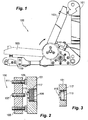
- FIG. 1 an illustrative view of an embodiment of an assembly in accordance with the disclosure is shown in Fig. 1 and is designated generally by reference character 100.
- FIG. 2 and 3 Other embodiments and/or aspects of this disclosure are shown in Figs. 2 and 3 .
- an optical system mount assembly 100 can include a first post 101 and a movable mount 103 configured to mount an optical element (not shown).
- the moveable mount 103 can be configured to move relative to the first post 101 assembly between a first position (e.g., as shown in Fig. 1 ) and a second position (e.g., as shown in phantom in Fig. 1 ), as shown this is using a pivot around an axis/axle.
- the assembly 100 can include a first magnetic latch system member 105 disposed on or within the first post 101.
- the assembly 100 can also include a second magnetic latch system member 107 disposed on or within the moveable mount 103 such that the first magnetic latch system member 105 magnetically interacts with the second magnetic latch system member 107 to magnetically latch the moveable mount 103 to the first post 101 in the first position (e.g., as shown in Figs. 1 and 2 ).
- the first and second magnetic latch system members 105, 107 can be configured to have or produce any suitable attraction force between each other.
- the first magnetic latch system member 105 can be or include a permanent magnet. In certain embodiments, the first magnetic latch system member 105 can be or include a rare earth magnet, for example.
- the second magnetic latch system member 107 can be or include a ferromagnetic element.
- the ferromagnetic element can be a metallic screw, e.g., as shown in Fig. 2 , and can be threaded to the moveable mount 103. Any other suitable structure is contemplated herein for the second magnetic latch system member 107.
- the second magnetic latch system member 107 can be a permanent magnet.
- At least one of the first magnetic latch system member 105 and the second magnetic latch system member 107 can be adjustable such that an attraction force between the first magnetic latch system member 105 and the second magnetic latch system member 107 is adjustable.
- the second latch system member 107 can be moveable relative to the movable mount 103 to change the distance of the second magnetic latch system member 107 relative to the first magnetic latch system member 105 when in the first position.
- the first position can be an upright alignment position as shown.
- the optical element can be a mirror and, therefore, the moveable mount 103 can be a mirror mount.
- the assembly 100 can further include one or more stop members (e.g., stop members 109, 111) extending from at least one of the first post member 101 or the moveable mount 103.
- the one or more stop members can include one or more fixed stop members 109 disposed on the first post member 101.
- the one or more fixed stop members 109 can include three or more fixed stop members 109, for example, or any other suitable number.
- the one or more stop members can include one or more adjustable stop members 111 configured to allow adjustment of the distance between the first post 101 and the moveable mount 103 in the first position, e.g., to allow alignment of the optical element and/or to allow adjustment of an attraction force between the first magnetic latch system member 105 and the second magnetic latch system member 107.
- the one or more adjustable stop members 111 can be disposed on and/or at least partly in the moveable mount 103 configured to contact the first post 101 and/or a stop member (e.g., a fixed stop member 109) extending from the first post 101 in the first position. Any other suitable position and/or arrangement for the stop members 109, 111 is contemplated herein.
- the one or more adjustable stop members 111 can include a screw threaded to the moveable mount 103, for example.
- the one or more adjustable stop members 111 may be made of non-ferrous material, for example, or any other suitable material.
- the one or more stop members 109, 111 can include any suitable material (e.g., hardened steel), ferrous or otherwise.
- the first magnetic latch system member 105 can be disposed within a pocket 113 defined in the first post 101.
- the first post 101 can include an opening 115 defined therethrough to reduce or eliminate magnetic interference of the first post 101 with the first magnetic latch system member 105.
- the opening 115 can be smaller than the first magnetic latch system member 105, for example, e.g., to retain the first magnetic latch system member 105 to the first post 101.
- the first post 101 can be made of aluminum, for example, or any other suitable material.
- the first magnetic latch system member 105 (e.g., a permanent magnet) can be attached to the first post 101 in any suitable manner.
- the first magnetic latch system member 105 can be attached in the pocket 113 using an adhesive 117 (e.g., RTV).
- an assembly include a second post structure 119. It is contemplated that the second post structure 119 can include another magnetic latch system member (e.g., member 105 and/or member 109) configured to magnetically interact with the mirror mount 103 in the second position, e.g., as shown in phantom in Fig. 1 .
- another magnetic latch system member e.g., member 105 and/or member 109 configured to magnetically interact with the mirror mount 103 in the second position, e.g., as shown in phantom in Fig. 1 .
- Embodiments can include a mirror housing that is retained with interacting magnetic latch members to a post to have a positive force retaining to a stop to maintain optical alignment or as shown, to maintain the mirror in the "stowed" position.
- the interaction force is strong enough to counteract forces of flying an aircraft to retain optical alignment under all operating conditions.
- an opening defined through the post can allow a smaller magnet to be used to generate same force because there is no material front blocking the magnetic field.
- Embodiments can use a magnet with an adjuster ferrous material or other magnet to form a magnetic latch, which allows the removal of the traditional flexure, and which makes the adjustment of the assembly simpler and less costly.
- any numerical values disclosed herein can be exact values or can be values within a range. Further, any terms of approximation (e.g., “about”, “approximately”, “around”) used in this disclosure can mean the stated value within a range. For example, in certain embodiments, the range can be within (plus or minus) 20%, or within 10%, or within 5%, or within 2%, or within any other suitable percentage or number as appreciated by those having ordinary skill in the art (e.g., for known tolerance limits or error ranges).
Landscapes
- Physics & Mathematics (AREA)
- General Physics & Mathematics (AREA)
- Optics & Photonics (AREA)
- Mounting And Adjusting Of Optical Elements (AREA)
- Optical Communication System (AREA)
Abstract
Description
- The present disclosure relates to mounts for optical systems, e.g., for mirror systems used in aircraft or other vehicles.
- Optical systems (e.g., mirror systems) and mounting systems therefore (e.g., mirror mounting systems) can be used in aircraft for or other vehicles. Traditional systems use hard stops along with costly flexures (e.g., a complex leaf spring) to ensure mechanism mirrors maintain optical alignment under all operating loads of the aircraft or other vehicle.
- Such conventional methods and systems have generally been considered satisfactory for their intended purpose. However, there is still a need in the art for improved optical system mounts. The present disclosure provides a solution for this need.
- An optical system mount assembly can include a first post and a movable mount configured to mount an optical element, the moveable mount being configured to move relative to the first post assembly between a first position and a second position. The assembly can include a first magnetic latch system member disposed on or within the first post, and a second magnetic latch system member disposed on or within the moveable mount such that the first magnetic latch system member magnetically interacts with the second magnetic latch system member to magnetically latch the moveable mount to the first post in the first position.
- In certain embodiments, the first magnetic latch system member can be a permanent magnet. For example, the first latch system member can be a rare-earth magnet.
- In certain embodiments, the second magnetic latch system member can be a ferromagnetic element. For example, the ferromagnetic element can be a metallic screw. In certain embodiments, the second magnetic latch system member can be a permanent magnet.
- At least one of the first magnetic latch system member and the second magnetic latch system member can be adjustable such that an attraction force between the first magnetic latch system member and the second magnetic latch system member is adjustable. For example, the second latch system member can be moveable relative to the movable mount to change the distance of the second magnetic latch system member relative to the first magnetic latch system member when in the first position.
- The first position can be an upright alignment position. The optical element can be a mirror and, therefore, the moveable mount can be a mirror mount.
- The assembly can further include one or more stop members extending from at least one of the first post member or the moveable mount. The one or more stop members can include one or more fixed stop members disposed on the first post member. The one or more fixed stop members can include three or more fixed stop members, for example, or any other suitable number, depending on the platform or mirror adjustment application.
- The one or more stop members can include one or more adjustable stop members configured to allow adjustment of the distance between the first post and the moveable mount in the first position to allow alignment of the optical element and/or to allow adjustment of an attraction force between the first magnetic latch system member and the second magnetic latch system member. The one or more adjustable stop members can be disposed on and/or at least partly in the moveable mount configured to contact the first post and/or a stop member extending therefrom in the first position. Any other suitable position is contemplated herein.
- The one or more adjustable stop members can include a screw threaded to the moveable mount, for example. The one or more adjustable stop members may be made of non-ferrous material, for example.
- In certain embodiments, the first magnetic latch system member can be disposed within a pocket defined in the first post. The first post can include an opening defined therethrough to reduce or eliminate magnetic interference of the first post with the first magnetic latch system member. The opening can be smaller than the first magnetic latch system member, for example. The first post can be made of aluminum, for example, or any other suitable material.
- These and other features of the systems and methods of the subject disclosure will become more readily apparent to those skilled in the art from the following detailed description taken in conjunction with the drawings.
- So that those skilled in the art to which the subject disclosure appertains will readily understand how to make and use the devices and methods of the subject disclosure without undue experimentation, embodiments thereof will be described in detail herein below with reference to certain figures, wherein:
-
Fig. 1 is a side view of an embodiment of an assembly in accordance with this disclosure, showing a mirror mount in a first position and in a second, down position (in phantom); -
Fig. 2 is a cross-sectional view of an embodiment of an assembly in accordance with this disclosure; and -
Fig. 3 is a cross-sectional view of an embodiment of a post in accordance with this disclosure. - Reference will now be made to the drawings wherein like reference numerals identify similar structural features or aspects of the subject disclosure. For purposes of explanation and illustration, and not limitation, an illustrative view of an embodiment of an assembly in accordance with the disclosure is shown in
Fig. 1 and is designated generally byreference character 100. Other embodiments and/or aspects of this disclosure are shown inFigs. 2 and 3 . - Referring to
Fig. 1 , an opticalsystem mount assembly 100 can include afirst post 101 and amovable mount 103 configured to mount an optical element (not shown). Themoveable mount 103 can be configured to move relative to thefirst post 101 assembly between a first position (e.g., as shown inFig. 1 ) and a second position (e.g., as shown in phantom inFig. 1 ), as shown this is using a pivot around an axis/axle. - Referring additionally to
Fig. 2 , theassembly 100 can include a first magneticlatch system member 105 disposed on or within thefirst post 101. Theassembly 100 can also include a second magneticlatch system member 107 disposed on or within themoveable mount 103 such that the first magneticlatch system member 105 magnetically interacts with the second magneticlatch system member 107 to magnetically latch themoveable mount 103 to thefirst post 101 in the first position (e.g., as shown inFigs. 1 and 2 ). The first and second magneticlatch system members - In certain embodiments, the first magnetic
latch system member 105 can be or include a permanent magnet. In certain embodiments, the first magneticlatch system member 105 can be or include a rare earth magnet, for example. - In certain embodiments, the second magnetic
latch system member 107 can be or include a ferromagnetic element. For example, the ferromagnetic element can be a metallic screw, e.g., as shown inFig. 2 , and can be threaded to themoveable mount 103. Any other suitable structure is contemplated herein for the second magneticlatch system member 107. In certain embodiments, the second magneticlatch system member 107 can be a permanent magnet. - At least one of the first magnetic
latch system member 105 and the second magneticlatch system member 107 can be adjustable such that an attraction force between the first magneticlatch system member 105 and the second magneticlatch system member 107 is adjustable. For example, the secondlatch system member 107 can be moveable relative to themovable mount 103 to change the distance of the second magneticlatch system member 107 relative to the first magneticlatch system member 105 when in the first position. - In certain embodiments, the first position can be an upright alignment position as shown. The optical element can be a mirror and, therefore, the
moveable mount 103 can be a mirror mount. - The
assembly 100 can further include one or more stop members (e.g.,stop members 109, 111) extending from at least one of the firstpost member 101 or themoveable mount 103. The one or more stop members can include one or more fixedstop members 109 disposed on the firstpost member 101. The one or more fixedstop members 109 can include three or more fixedstop members 109, for example, or any other suitable number. - The one or more stop members can include one or more
adjustable stop members 111 configured to allow adjustment of the distance between thefirst post 101 and themoveable mount 103 in the first position, e.g., to allow alignment of the optical element and/or to allow adjustment of an attraction force between the first magneticlatch system member 105 and the second magneticlatch system member 107. The one or moreadjustable stop members 111 can be disposed on and/or at least partly in themoveable mount 103 configured to contact thefirst post 101 and/or a stop member (e.g., a fixed stop member 109) extending from thefirst post 101 in the first position. Any other suitable position and/or arrangement for thestop members - As shown in
Fig. 2 , the one or moreadjustable stop members 111 can include a screw threaded to themoveable mount 103, for example. The one or moreadjustable stop members 111 may be made of non-ferrous material, for example, or any other suitable material. The one ormore stop members - In certain embodiments, referring additionally to
Fig. 3 , the first magneticlatch system member 105 can be disposed within apocket 113 defined in thefirst post 101. Thefirst post 101 can include anopening 115 defined therethrough to reduce or eliminate magnetic interference of thefirst post 101 with the first magneticlatch system member 105. Theopening 115 can be smaller than the first magneticlatch system member 105, for example, e.g., to retain the first magneticlatch system member 105 to thefirst post 101. Thefirst post 101 can be made of aluminum, for example, or any other suitable material. - The first magnetic latch system member 105 (e.g., a permanent magnet) can be attached to the
first post 101 in any suitable manner. For example, the first magneticlatch system member 105 can be attached in thepocket 113 using an adhesive 117 (e.g., RTV). - Certain embodiments of an assembly include a
second post structure 119. It is contemplated that thesecond post structure 119 can include another magnetic latch system member (e.g.,member 105 and/or member 109) configured to magnetically interact with themirror mount 103 in the second position, e.g., as shown in phantom inFig. 1 . - Embodiments can include a mirror housing that is retained with interacting magnetic latch members to a post to have a positive force retaining to a stop to maintain optical alignment or as shown, to maintain the mirror in the "stowed" position. In certain embodiments, the interaction force is strong enough to counteract forces of flying an aircraft to retain optical alignment under all operating conditions. In certain embodiments an opening defined through the post can allow a smaller magnet to be used to generate same force because there is no material front blocking the magnetic field.
- Embodiments can use a magnet with an adjuster ferrous material or other magnet to form a magnetic latch, which allows the removal of the traditional flexure, and which makes the adjustment of the assembly simpler and less costly.
- Any suitable combination(s) of any disclosed embodiments and/or any suitable portion(s) thereof are contemplated herein as appreciated by those having ordinary skill in the art.
- Those having ordinary skill in the art understand that any numerical values disclosed herein can be exact values or can be values within a range. Further, any terms of approximation (e.g., "about", "approximately", "around") used in this disclosure can mean the stated value within a range. For example, in certain embodiments, the range can be within (plus or minus) 20%, or within 10%, or within 5%, or within 2%, or within any other suitable percentage or number as appreciated by those having ordinary skill in the art (e.g., for known tolerance limits or error ranges).
- The embodiments of the present disclosure, as described above and shown in the drawings, provide for improvement in the art to which they pertain. While the subject disclosure includes reference to certain embodiments, those skilled in the art will readily appreciate that changes and/or modifications may be made thereto without departing from the scope of the invention as defined by the claims.
Claims (15)
- An optical system mount assembly, comprising:a first post (101);a movable mount (103) configured to mount an optical element, wherein the moveable mount is configured to move relative to the first post assembly between a first position and a second position;a first magnetic latch system member (105) disposed on or within the first post; anda second magnetic latch system member (107) disposed on or within the moveable mount such that the first magnetic latch system member magnetically interacts with the second magnetic latch system member to magnetically latch the moveable mount to the first post in the first position.
- The assembly of claim 1, wherein the first magnetic latch system member is a permanent magnet.
- The assembly of claim 2, wherein the second magnetic latch system member is a ferromagnetic element.
- The assembly of claim 3, wherein the ferromagnetic element is a metallic screw.
- The assembly of any preceding claim, wherein at least one of the first magnetic latch system member and the second magnetic latch system member is adjustable such that an attraction force between the first magnetic latch system member and the second magnetic latch system member is adjustable.
- The assembly of claim 5, wherein the second latch system member is moveable relative to the movable mount to change the distance of the second magnetic latch system member relative to the first magnetic latch system member when in the first position.
- The assembly of any preceding claim, wherein the first position is an upright alignment position.
- The assembly of claim 7, wherein the optical element is a mirror and the moveable mount is a mirror mount.
- The assembly of any preceding claim, further comprising one or more stop members (109, 111) extending from at least one of the first post member or the moveable mount.
- The assembly of claim 9, wherein the one or more stop members includes one or more fixed stop members disposed on the first post member, and preferably wherein the one or more fixed stop members includes three or more fixed stop members; or wherein the one or more stop members includes one or more adjustable stop members configured to allow adjustment of the distance between the first post and the moveable mount in the first position to allow alignment of the optical element and/or to allow adjustment of an attraction force between the first magnetic latch system member and the second magnetic latch system member, and preferably wherein the one or more adjustable stop members are disposed on and/or at least partly in the moveable mount configured to contact the first post and/or a stop member extending therefrom in the first position, and preferably wherein the one or more adjustable stop members include a screw threaded to the moveable mount.
- The assembly of claim 9 or 10, wherein the one or more adjustable stop members are made of non-ferrous material.
- The assembly of any preceding claim, wherein the first magnetic latch system member is disposed within a pocket (113) defined in the first post.
- The assembly of claim 12, wherein the first post includes an opening defined therethrough to reduce or eliminate magnetic interference of the first post with the first magnetic latch system member.
- The assembly of claim 13, wherein the opening is smaller than the first magnetic latch system member.
- The assembly of claim 14, wherein the first post is made of aluminum.
Applications Claiming Priority (1)
| Application Number | Priority Date | Filing Date | Title |
|---|---|---|---|
| US16/057,510 US11022778B2 (en) | 2018-08-07 | 2018-08-07 | Optical system mounts |
Publications (2)
| Publication Number | Publication Date |
|---|---|
| EP3608700A1 true EP3608700A1 (en) | 2020-02-12 |
| EP3608700B1 EP3608700B1 (en) | 2024-07-17 |
Family
ID=67544040
Family Applications (1)
| Application Number | Title | Priority Date | Filing Date |
|---|---|---|---|
| EP19189847.7A Active EP3608700B1 (en) | 2018-08-07 | 2019-08-02 | Optical system mounts |
Country Status (3)
| Country | Link |
|---|---|
| US (1) | US11022778B2 (en) |
| EP (1) | EP3608700B1 (en) |
| IL (1) | IL268384B2 (en) |
Citations (4)
| Publication number | Priority date | Publication date | Assignee | Title |
|---|---|---|---|---|
| JPS579911U (en) * | 1980-06-13 | 1982-01-19 | ||
| US5638222A (en) * | 1994-06-29 | 1997-06-10 | Olympus Optical Co., Ltd. | Optical element positioning device |
| JP2003029184A (en) * | 2001-07-11 | 2003-01-29 | Ricoh Co Ltd | Optical scanning device and image forming apparatus |
| US20170139181A1 (en) * | 2015-02-02 | 2017-05-18 | Xing Du | Imaging system with movable tray of selectable optical elements |
Family Cites Families (17)
| Publication number | Priority date | Publication date | Assignee | Title |
|---|---|---|---|---|
| US2985749A (en) * | 1960-01-14 | 1961-05-23 | Earl A Johnson | Headlight reflector |
| US3589049A (en) * | 1969-07-08 | 1971-06-29 | Thelma L Cornelius | Picture frame box with record holder |
| US4078859A (en) * | 1976-06-01 | 1978-03-14 | Sharett Terrence E | Automatic rear view mirror |
| US4281898A (en) * | 1979-02-07 | 1981-08-04 | Murakami Kaimeido Co., Ltd. | Automatic antiglare rearview mirror |
| JPS579911A (en) | 1980-05-20 | 1982-01-19 | Mitsui Eng & Shipbuild Co Ltd | Landing/elevating system marine work platform |
| US4390234A (en) * | 1980-08-14 | 1983-06-28 | Embach James T | Viewer/projector for display of 360 degree holographic film cassettes |
| FR2629768B1 (en) * | 1988-04-06 | 1992-02-28 | Rockwell Cim | MIRROR CASSETTE FOR SUN VISOR, ESPECIALLY IN AN AUTOMOBILE INTERIOR |
| US4906087A (en) * | 1989-06-16 | 1990-03-06 | Litton Systems, Inc. | Magneto-retractive deformable mirror |
| KR910007134B1 (en) * | 1989-11-29 | 1991-09-18 | 풍정산업 주식회사 | Rear-view mirror |
| ES2024963A6 (en) * | 1990-12-21 | 1992-03-01 | Ind Techno Matic Sa | Semi-automatic opening and closing device for sun visor mirrors provided with a hinged cover. |
| DE19521654C2 (en) * | 1995-06-14 | 1999-01-07 | Wolf Gmbh Richard | Optical device |
| US5953052A (en) * | 1995-09-20 | 1999-09-14 | Videotronic Systems | Reflected display teleconferencing eye contact terminal |
| US5907433A (en) | 1997-06-16 | 1999-05-25 | Versatron Corporation | Compact variable field of view optical system |
| JP3892567B2 (en) * | 1998-02-02 | 2007-03-14 | 茂樹 小林 | Opening and closing type orthogonal mirror |
| JP2000217682A (en) * | 1999-01-28 | 2000-08-08 | Shigeki Kobayashi | Open/close type orthogonal mirror and its manufacture |
| US8614742B2 (en) | 2007-06-06 | 2013-12-24 | Palo Alto Research Center Incorporated | Miniature low cost pan/tilt magnetic actuation for portable and stationary video cameras |
| JP6309765B2 (en) | 2010-12-20 | 2018-04-11 | カール・ツァイス・エスエムティー・ゲーエムベーハー | Arrangement for mounting optical elements |
-
2018
- 2018-08-07 US US16/057,510 patent/US11022778B2/en active Active
-
2019
- 2019-07-31 IL IL268384A patent/IL268384B2/en unknown
- 2019-08-02 EP EP19189847.7A patent/EP3608700B1/en active Active
Patent Citations (4)
| Publication number | Priority date | Publication date | Assignee | Title |
|---|---|---|---|---|
| JPS579911U (en) * | 1980-06-13 | 1982-01-19 | ||
| US5638222A (en) * | 1994-06-29 | 1997-06-10 | Olympus Optical Co., Ltd. | Optical element positioning device |
| JP2003029184A (en) * | 2001-07-11 | 2003-01-29 | Ricoh Co Ltd | Optical scanning device and image forming apparatus |
| US20170139181A1 (en) * | 2015-02-02 | 2017-05-18 | Xing Du | Imaging system with movable tray of selectable optical elements |
Also Published As
| Publication number | Publication date |
|---|---|
| IL268384A (en) | 2020-02-27 |
| EP3608700B1 (en) | 2024-07-17 |
| IL268384B2 (en) | 2023-11-01 |
| US20200049944A1 (en) | 2020-02-13 |
| US11022778B2 (en) | 2021-06-01 |
| IL268384B1 (en) | 2023-07-01 |
Similar Documents
| Publication | Publication Date | Title |
|---|---|---|
| US9593699B2 (en) | Fastener device for fastening a panel to a structure, and an aircraft | |
| WO2020144461A1 (en) | Mount, accessory and assembly | |
| WO2011007628A1 (en) | Small size mirror tilt actuator | |
| US9221397B1 (en) | Variable magnetic break-away mounting mechanism | |
| US8625212B2 (en) | System for guiding optical elements | |
| EP3608700B1 (en) | Optical system mounts | |
| DE102017202182A1 (en) | Reluctance actuator | |
| WO2014149169A1 (en) | Reaction compensated tilt platform | |
| US10222754B2 (en) | Anti-shock device for a timepiece movement | |
| DE112023003531T5 (en) | Systems and methods for coupling a locking plate and an actuator | |
| DE3215212A1 (en) | ROD SENSOR FOR SPEED MEASUREMENT | |
| EP0376107A2 (en) | Telescope with image stabilisation | |
| EP0376108A2 (en) | Telescope with image stabilisation | |
| CN109899433B (en) | System and method for damping dynamic loading | |
| DE2947131A1 (en) | CONTROL DEVICE FOR OPTICAL INSTRUMENTS | |
| US10734148B2 (en) | Electromagnetic holding magnet and method for manufacturing, electromagnetic locking element and use of the same | |
| US1915631A (en) | Electromagnet paint striping template | |
| US10138667B2 (en) | Spring and/or damping element | |
| US2994245A (en) | Optical sighting device | |
| EP3627203B1 (en) | Optical system mounts | |
| US5329265A (en) | Intermediate support relay for use particularly in motor vehicles | |
| WO2024088482A1 (en) | Device and method for controlling movements of an object in an open- and/or closed-loop manner | |
| US20130201571A1 (en) | Hinge mechanism for small optics and related methods | |
| US3145248A (en) | Optical sight displacing glass | |
| US12007211B2 (en) | Manually resettable missile fin lock assembly |
Legal Events
| Date | Code | Title | Description |
|---|---|---|---|
| PUAI | Public reference made under article 153(3) epc to a published international application that has entered the european phase |
Free format text: ORIGINAL CODE: 0009012 |
|
| STAA | Information on the status of an ep patent application or granted ep patent |
Free format text: STATUS: THE APPLICATION HAS BEEN PUBLISHED |
|
| AK | Designated contracting states |
Kind code of ref document: A1 Designated state(s): AL AT BE BG CH CY CZ DE DK EE ES FI FR GB GR HR HU IE IS IT LI LT LU LV MC MK MT NL NO PL PT RO RS SE SI SK SM TR |
|
| STAA | Information on the status of an ep patent application or granted ep patent |
Free format text: STATUS: REQUEST FOR EXAMINATION WAS MADE |
|
| 17P | Request for examination filed |
Effective date: 20200812 |
|
| RBV | Designated contracting states (corrected) |
Designated state(s): AL AT BE BG CH CY CZ DE DK EE ES FI FR GB GR HR HU IE IS IT LI LT LU LV MC MK MT NL NO PL PT RO RS SE SI SK SM TR |
|
| STAA | Information on the status of an ep patent application or granted ep patent |
Free format text: STATUS: EXAMINATION IS IN PROGRESS |
|
| 17Q | First examination report despatched |
Effective date: 20220615 |
|
| P01 | Opt-out of the competence of the unified patent court (upc) registered |
Effective date: 20230922 |
|
| GRAP | Despatch of communication of intention to grant a patent |
Free format text: ORIGINAL CODE: EPIDOSNIGR1 |
|
| STAA | Information on the status of an ep patent application or granted ep patent |
Free format text: STATUS: GRANT OF PATENT IS INTENDED |
|
| INTG | Intention to grant announced |
Effective date: 20240215 |
|
| RIN1 | Information on inventor provided before grant (corrected) |
Inventor name: HELMKE, CHRISTOPHER WILLIAM Inventor name: SIM, GORDON Inventor name: LANGE, DAVIS Inventor name: ASSELIN, LUKE N. |
|
| GRAS | Grant fee paid |
Free format text: ORIGINAL CODE: EPIDOSNIGR3 |
|
| GRAA | (expected) grant |
Free format text: ORIGINAL CODE: 0009210 |
|
| STAA | Information on the status of an ep patent application or granted ep patent |
Free format text: STATUS: THE PATENT HAS BEEN GRANTED |
|
| AK | Designated contracting states |
Kind code of ref document: B1 Designated state(s): AL AT BE BG CH CY CZ DE DK EE ES FI FR GB GR HR HU IE IS IT LI LT LU LV MC MK MT NL NO PL PT RO RS SE SI SK SM TR |
|
| REG | Reference to a national code |
Ref country code: CH Ref legal event code: EP |
|
| REG | Reference to a national code |
Ref country code: DE Ref legal event code: R096 Ref document number: 602019055274 Country of ref document: DE |
|
| REG | Reference to a national code |
Ref country code: IE Ref legal event code: FG4D |
|
| REG | Reference to a national code |
Ref country code: LT Ref legal event code: MG9D |
|
| REG | Reference to a national code |
Ref country code: NL Ref legal event code: MP Effective date: 20240717 |
|
| PG25 | Lapsed in a contracting state [announced via postgrant information from national office to epo] |
Ref country code: PT Free format text: LAPSE BECAUSE OF FAILURE TO SUBMIT A TRANSLATION OF THE DESCRIPTION OR TO PAY THE FEE WITHIN THE PRESCRIBED TIME-LIMIT Effective date: 20241118 |
|
| REG | Reference to a national code |
Ref country code: AT Ref legal event code: MK05 Ref document number: 1704684 Country of ref document: AT Kind code of ref document: T Effective date: 20240717 |
|
| PG25 | Lapsed in a contracting state [announced via postgrant information from national office to epo] |
Ref country code: NL Free format text: LAPSE BECAUSE OF FAILURE TO SUBMIT A TRANSLATION OF THE DESCRIPTION OR TO PAY THE FEE WITHIN THE PRESCRIBED TIME-LIMIT Effective date: 20240717 |
|
| PG25 | Lapsed in a contracting state [announced via postgrant information from national office to epo] |
Ref country code: PT Free format text: LAPSE BECAUSE OF FAILURE TO SUBMIT A TRANSLATION OF THE DESCRIPTION OR TO PAY THE FEE WITHIN THE PRESCRIBED TIME-LIMIT Effective date: 20241118 Ref country code: NL Free format text: LAPSE BECAUSE OF FAILURE TO SUBMIT A TRANSLATION OF THE DESCRIPTION OR TO PAY THE FEE WITHIN THE PRESCRIBED TIME-LIMIT Effective date: 20240717 |
|
| PG25 | Lapsed in a contracting state [announced via postgrant information from national office to epo] |
Ref country code: NO Free format text: LAPSE BECAUSE OF FAILURE TO SUBMIT A TRANSLATION OF THE DESCRIPTION OR TO PAY THE FEE WITHIN THE PRESCRIBED TIME-LIMIT Effective date: 20241017 |
|
| PG25 | Lapsed in a contracting state [announced via postgrant information from national office to epo] |
Ref country code: FI Free format text: LAPSE BECAUSE OF FAILURE TO SUBMIT A TRANSLATION OF THE DESCRIPTION OR TO PAY THE FEE WITHIN THE PRESCRIBED TIME-LIMIT Effective date: 20240717 Ref country code: GR Free format text: LAPSE BECAUSE OF FAILURE TO SUBMIT A TRANSLATION OF THE DESCRIPTION OR TO PAY THE FEE WITHIN THE PRESCRIBED TIME-LIMIT Effective date: 20241018 Ref country code: PL Free format text: LAPSE BECAUSE OF FAILURE TO SUBMIT A TRANSLATION OF THE DESCRIPTION OR TO PAY THE FEE WITHIN THE PRESCRIBED TIME-LIMIT Effective date: 20240717 |
|
| PG25 | Lapsed in a contracting state [announced via postgrant information from national office to epo] |
Ref country code: BG Free format text: LAPSE BECAUSE OF FAILURE TO SUBMIT A TRANSLATION OF THE DESCRIPTION OR TO PAY THE FEE WITHIN THE PRESCRIBED TIME-LIMIT Effective date: 20240717 |
|
| PG25 | Lapsed in a contracting state [announced via postgrant information from national office to epo] |
Ref country code: LV Free format text: LAPSE BECAUSE OF FAILURE TO SUBMIT A TRANSLATION OF THE DESCRIPTION OR TO PAY THE FEE WITHIN THE PRESCRIBED TIME-LIMIT Effective date: 20240717 |
|
| PG25 | Lapsed in a contracting state [announced via postgrant information from national office to epo] |
Ref country code: IS Free format text: LAPSE BECAUSE OF FAILURE TO SUBMIT A TRANSLATION OF THE DESCRIPTION OR TO PAY THE FEE WITHIN THE PRESCRIBED TIME-LIMIT Effective date: 20241117 Ref country code: AT Free format text: LAPSE BECAUSE OF FAILURE TO SUBMIT A TRANSLATION OF THE DESCRIPTION OR TO PAY THE FEE WITHIN THE PRESCRIBED TIME-LIMIT Effective date: 20240717 |
|
| PG25 | Lapsed in a contracting state [announced via postgrant information from national office to epo] |
Ref country code: HR Free format text: LAPSE BECAUSE OF FAILURE TO SUBMIT A TRANSLATION OF THE DESCRIPTION OR TO PAY THE FEE WITHIN THE PRESCRIBED TIME-LIMIT Effective date: 20240717 |
|
| PG25 | Lapsed in a contracting state [announced via postgrant information from national office to epo] |
Ref country code: RS Free format text: LAPSE BECAUSE OF FAILURE TO SUBMIT A TRANSLATION OF THE DESCRIPTION OR TO PAY THE FEE WITHIN THE PRESCRIBED TIME-LIMIT Effective date: 20241017 Ref country code: ES Free format text: LAPSE BECAUSE OF FAILURE TO SUBMIT A TRANSLATION OF THE DESCRIPTION OR TO PAY THE FEE WITHIN THE PRESCRIBED TIME-LIMIT Effective date: 20240717 |
|
| PG25 | Lapsed in a contracting state [announced via postgrant information from national office to epo] |
Ref country code: RS Free format text: LAPSE BECAUSE OF FAILURE TO SUBMIT A TRANSLATION OF THE DESCRIPTION OR TO PAY THE FEE WITHIN THE PRESCRIBED TIME-LIMIT Effective date: 20241017 Ref country code: PL Free format text: LAPSE BECAUSE OF FAILURE TO SUBMIT A TRANSLATION OF THE DESCRIPTION OR TO PAY THE FEE WITHIN THE PRESCRIBED TIME-LIMIT Effective date: 20240717 Ref country code: NO Free format text: LAPSE BECAUSE OF FAILURE TO SUBMIT A TRANSLATION OF THE DESCRIPTION OR TO PAY THE FEE WITHIN THE PRESCRIBED TIME-LIMIT Effective date: 20241017 Ref country code: LV Free format text: LAPSE BECAUSE OF FAILURE TO SUBMIT A TRANSLATION OF THE DESCRIPTION OR TO PAY THE FEE WITHIN THE PRESCRIBED TIME-LIMIT Effective date: 20240717 Ref country code: IS Free format text: LAPSE BECAUSE OF FAILURE TO SUBMIT A TRANSLATION OF THE DESCRIPTION OR TO PAY THE FEE WITHIN THE PRESCRIBED TIME-LIMIT Effective date: 20241117 Ref country code: HR Free format text: LAPSE BECAUSE OF FAILURE TO SUBMIT A TRANSLATION OF THE DESCRIPTION OR TO PAY THE FEE WITHIN THE PRESCRIBED TIME-LIMIT Effective date: 20240717 Ref country code: GR Free format text: LAPSE BECAUSE OF FAILURE TO SUBMIT A TRANSLATION OF THE DESCRIPTION OR TO PAY THE FEE WITHIN THE PRESCRIBED TIME-LIMIT Effective date: 20241018 Ref country code: FI Free format text: LAPSE BECAUSE OF FAILURE TO SUBMIT A TRANSLATION OF THE DESCRIPTION OR TO PAY THE FEE WITHIN THE PRESCRIBED TIME-LIMIT Effective date: 20240717 Ref country code: ES Free format text: LAPSE BECAUSE OF FAILURE TO SUBMIT A TRANSLATION OF THE DESCRIPTION OR TO PAY THE FEE WITHIN THE PRESCRIBED TIME-LIMIT Effective date: 20240717 Ref country code: BG Free format text: LAPSE BECAUSE OF FAILURE TO SUBMIT A TRANSLATION OF THE DESCRIPTION OR TO PAY THE FEE WITHIN THE PRESCRIBED TIME-LIMIT Effective date: 20240717 Ref country code: AT Free format text: LAPSE BECAUSE OF FAILURE TO SUBMIT A TRANSLATION OF THE DESCRIPTION OR TO PAY THE FEE WITHIN THE PRESCRIBED TIME-LIMIT Effective date: 20240717 |
|
| REG | Reference to a national code |
Ref country code: CH Ref legal event code: PL |
|
| PG25 | Lapsed in a contracting state [announced via postgrant information from national office to epo] |
Ref country code: SM Free format text: LAPSE BECAUSE OF FAILURE TO SUBMIT A TRANSLATION OF THE DESCRIPTION OR TO PAY THE FEE WITHIN THE PRESCRIBED TIME-LIMIT Effective date: 20240717 Ref country code: DK Free format text: LAPSE BECAUSE OF FAILURE TO SUBMIT A TRANSLATION OF THE DESCRIPTION OR TO PAY THE FEE WITHIN THE PRESCRIBED TIME-LIMIT Effective date: 20240717 Ref country code: RO Free format text: LAPSE BECAUSE OF FAILURE TO SUBMIT A TRANSLATION OF THE DESCRIPTION OR TO PAY THE FEE WITHIN THE PRESCRIBED TIME-LIMIT Effective date: 20240717 |
|
| PG25 | Lapsed in a contracting state [announced via postgrant information from national office to epo] |
Ref country code: LU Free format text: LAPSE BECAUSE OF NON-PAYMENT OF DUE FEES Effective date: 20240802 |
|
| REG | Reference to a national code |
Ref country code: DE Ref legal event code: R097 Ref document number: 602019055274 Country of ref document: DE |
|
| PG25 | Lapsed in a contracting state [announced via postgrant information from national office to epo] |
Ref country code: EE Free format text: LAPSE BECAUSE OF FAILURE TO SUBMIT A TRANSLATION OF THE DESCRIPTION OR TO PAY THE FEE WITHIN THE PRESCRIBED TIME-LIMIT Effective date: 20240717 Ref country code: MC Free format text: LAPSE BECAUSE OF FAILURE TO SUBMIT A TRANSLATION OF THE DESCRIPTION OR TO PAY THE FEE WITHIN THE PRESCRIBED TIME-LIMIT Effective date: 20240717 Ref country code: CH Free format text: LAPSE BECAUSE OF NON-PAYMENT OF DUE FEES Effective date: 20240831 |
|
| PG25 | Lapsed in a contracting state [announced via postgrant information from national office to epo] |
Ref country code: CZ Free format text: LAPSE BECAUSE OF FAILURE TO SUBMIT A TRANSLATION OF THE DESCRIPTION OR TO PAY THE FEE WITHIN THE PRESCRIBED TIME-LIMIT Effective date: 20240717 |
|
| PG25 | Lapsed in a contracting state [announced via postgrant information from national office to epo] |
Ref country code: SK Free format text: LAPSE BECAUSE OF FAILURE TO SUBMIT A TRANSLATION OF THE DESCRIPTION OR TO PAY THE FEE WITHIN THE PRESCRIBED TIME-LIMIT Effective date: 20240717 |
|
| PLBE | No opposition filed within time limit |
Free format text: ORIGINAL CODE: 0009261 |
|
| STAA | Information on the status of an ep patent application or granted ep patent |
Free format text: STATUS: NO OPPOSITION FILED WITHIN TIME LIMIT |
|
| 26N | No opposition filed |
Effective date: 20250422 |
|
| REG | Reference to a national code |
Ref country code: BE Ref legal event code: MM Effective date: 20240831 |
|
| PG25 | Lapsed in a contracting state [announced via postgrant information from national office to epo] |
Ref country code: BE Free format text: LAPSE BECAUSE OF NON-PAYMENT OF DUE FEES Effective date: 20240831 |
|
| PG25 | Lapsed in a contracting state [announced via postgrant information from national office to epo] |
Ref country code: IE Free format text: LAPSE BECAUSE OF NON-PAYMENT OF DUE FEES Effective date: 20240802 |
|
| PG25 | Lapsed in a contracting state [announced via postgrant information from national office to epo] |
Ref country code: SE Free format text: LAPSE BECAUSE OF FAILURE TO SUBMIT A TRANSLATION OF THE DESCRIPTION OR TO PAY THE FEE WITHIN THE PRESCRIBED TIME-LIMIT Effective date: 20240717 |
|
| PGFP | Annual fee paid to national office [announced via postgrant information from national office to epo] |
Ref country code: DE Payment date: 20250724 Year of fee payment: 7 |
|
| PGFP | Annual fee paid to national office [announced via postgrant information from national office to epo] |
Ref country code: GB Payment date: 20250725 Year of fee payment: 7 |
|
| PGFP | Annual fee paid to national office [announced via postgrant information from national office to epo] |
Ref country code: FR Payment date: 20250725 Year of fee payment: 7 |
|
| PG25 | Lapsed in a contracting state [announced via postgrant information from national office to epo] |
Ref country code: CY Free format text: LAPSE BECAUSE OF FAILURE TO SUBMIT A TRANSLATION OF THE DESCRIPTION OR TO PAY THE FEE WITHIN THE PRESCRIBED TIME-LIMIT; INVALID AB INITIO Effective date: 20190802 Ref country code: IT Free format text: LAPSE BECAUSE OF FAILURE TO SUBMIT A TRANSLATION OF THE DESCRIPTION OR TO PAY THE FEE WITHIN THE PRESCRIBED TIME-LIMIT Effective date: 20240717 |
|
| PG25 | Lapsed in a contracting state [announced via postgrant information from national office to epo] |
Ref country code: HU Free format text: LAPSE BECAUSE OF FAILURE TO SUBMIT A TRANSLATION OF THE DESCRIPTION OR TO PAY THE FEE WITHIN THE PRESCRIBED TIME-LIMIT; INVALID AB INITIO Effective date: 20190802 |