EP3608645A1 - Sensor device - Google Patents
Sensor device Download PDFInfo
- Publication number
- EP3608645A1 EP3608645A1 EP19190575.1A EP19190575A EP3608645A1 EP 3608645 A1 EP3608645 A1 EP 3608645A1 EP 19190575 A EP19190575 A EP 19190575A EP 3608645 A1 EP3608645 A1 EP 3608645A1
- Authority
- EP
- European Patent Office
- Prior art keywords
- holder
- circuit member
- magnetism collection
- sensor element
- suppression
- Prior art date
- Legal status (The legal status is an assumption and is not a legal conclusion. Google has not performed a legal analysis and makes no representation as to the accuracy of the status listed.)
- Granted
Links
Images



Classifications
-
- G—PHYSICS
- G01—MEASURING; TESTING
- G01L—MEASURING FORCE, STRESS, TORQUE, WORK, MECHANICAL POWER, MECHANICAL EFFICIENCY, OR FLUID PRESSURE
- G01L3/00—Measuring torque, work, mechanical power, or mechanical efficiency, in general
- G01L3/02—Rotary-transmission dynamometers
- G01L3/04—Rotary-transmission dynamometers wherein the torque-transmitting element comprises a torsionally-flexible shaft
- G01L3/10—Rotary-transmission dynamometers wherein the torque-transmitting element comprises a torsionally-flexible shaft involving electric or magnetic means for indicating
- G01L3/101—Rotary-transmission dynamometers wherein the torque-transmitting element comprises a torsionally-flexible shaft involving electric or magnetic means for indicating involving magnetic or electromagnetic means
- G01L3/104—Rotary-transmission dynamometers wherein the torque-transmitting element comprises a torsionally-flexible shaft involving electric or magnetic means for indicating involving magnetic or electromagnetic means involving permanent magnets
-
- H—ELECTRICITY
- H05—ELECTRIC TECHNIQUES NOT OTHERWISE PROVIDED FOR
- H05K—PRINTED CIRCUITS; CASINGS OR CONSTRUCTIONAL DETAILS OF ELECTRIC APPARATUS; MANUFACTURE OF ASSEMBLAGES OF ELECTRICAL COMPONENTS
- H05K5/00—Casings, cabinets or drawers for electric apparatus
- H05K5/02—Details
- H05K5/0247—Electrical details of casings, e.g. terminals, passages for cables or wiring
-
- H—ELECTRICITY
- H05—ELECTRIC TECHNIQUES NOT OTHERWISE PROVIDED FOR
- H05K—PRINTED CIRCUITS; CASINGS OR CONSTRUCTIONAL DETAILS OF ELECTRIC APPARATUS; MANUFACTURE OF ASSEMBLAGES OF ELECTRICAL COMPONENTS
- H05K5/00—Casings, cabinets or drawers for electric apparatus
- H05K5/06—Hermetically-sealed casings
- H05K5/065—Hermetically-sealed casings sealed by encapsulation, e.g. waterproof resin forming an integral casing, injection moulding
Definitions
- the present invention relates to a sensor device.
- JP 2015-191995 A discloses a device in which a circuit board on which an electronic component is mounted is surrounded by a holder and a housing is formed by injection molding so as to cover the holder.
- the holder may be deformed by a molding pressure applied during the injection molding of the housing.
- the deformed holder may contact the electronic component. If the deformed holder contacts the electronic component, the electronic component may be detached from the circuit board. In such a case, electrical connection between the electronic component and a circuit of the circuit board may become poor.
- An aspect of the present invention provides a sensor device including: a holder that surrounds a circuit member, to which an electronic component is electrically connected, and a sensor element electrically connected to the circuit member; and a housing formed by injection molding so as to cover the holder.
- a suppression portion is provided inside the holder. The suppression portion extends in a column shape so as to connect between inner portions of the holder in a direction of deformation of the holder due to a molding pressure during the injection molding in order to suppress the deformation.
- the suppression portion that is provided inside the holder engages to suppress deformation of the holder due to the molding pressure during the injection molding. This suppresses contact of the deformed holder with the circuit member. Therefore, it is possible to suppress separation of the electronic component from the circuit member due to such contact, and to suppress electrical connection between the circuit member and the sensor element becoming poor.
- the holder may be constituted from at least a first holder and a second holder, and surround the circuit member and the sensor element between the first holder and the second holder; the first holder may have a first holder body portion; and the second holder may have a second holder body portion that includes a placement portion, on which the circuit member and the sensor element are placed, and that faces the first holder body portion, and the suppression portion that projects from the second holder body portion toward the first holder body portion.
- the suppression portion that is provided on the second holder body portion of the second holder engages with the first holder body portion. Therefore, deformation of the first holder body portion and the second holder body portion can be suppressed. Thus, the circuit member and the sensor element that are placed on the placement portion of the second holder can be protected.
- the suppression portion is provided on the second holder body portion, on which the circuit member and the sensor element are placed. In this case, it is not necessary to pay attention to avoid contact of the suppression portion with the circuit member and the sensor element during assembly of the first holder and the second holder. This facilitates assembly between the first holder and the second holder.
- the sensor element may include a first sensor element and a second sensor element;
- the circuit member may include a first circuit member electrically connected to the first sensor element and a second circuit member electrically connected to the second sensor element; and the suppression portion may be disposed between the first circuit member and the second circuit member with a clearance from the first circuit member and the second circuit member.
- the suppression portion is disposed between the first circuit member and the second circuit member. Therefore, the arrangement of the suppression portion is suitable for suppressing contact of the first holder body portion with the first circuit member and the second circuit member. Interference between the sensor element and the circuit member and the suppression portion is suppressed, since the suppression portion is disposed with a clearance from the first circuit member and the second circuit member, when the sensor element and the circuit member are assembled to the second holder.
- the sensor element may include a first sensor element and a second sensor element;
- the circuit member may include a first circuit member electrically connected to the first sensor element and a second circuit member electrically connected to the second sensor element; and the suppression portion may be disposed between the first circuit member and the second circuit member in abutment with the first circuit member and the second circuit member.
- the suppression portion is disposed between the first circuit member and the second circuit member. Therefore, the arrangement of the suppression portion is suitable for suppressing contact of the first holder body portion with the first circuit member and the second circuit member.
- the position of assembly of the circuit member and the sensor element can be prescribed with reference to the suppression portion when the circuit member and the sensor element are assembled to the holder. Therefore, the circuit member and the sensor element can be positioned with respect to the holder using the suppression portion.
- the circuit member may include the electronic component and a conductor portion that is energizable; the first holder may have a projection portion that projects from the first holder body portion toward the second holder and that faces the conductor portion; and a projection length of the suppression portion may be set to be longer than a projection length of the projection portion.
- the sensor device may further include a permanent magnet attached to a first shaft and magnetized in a circumferential direction, a magnetic yoke that is fixed to a second shaft coupled to the first shaft via a coupling shaft and is disposed in a magnetic field formed by the permanent magnet, and a magnetism collection ring disposed so as to surround the magnetic yoke and configured to collect magnetic flux of the magnetic yoke;
- the magnetism collection ring may have an annular ring portion that surrounds the magnetic yoke and a magnetism collection portion that extends toward a radially outer side of the ring portion;
- the holder may have a magnetism collection portion holder that surrounds the magnetism collection portion, the sensor element, and the circuit member and that has a rectangular shape; a longitudinal direction of the magnetism collection portion holder may coincide with a direction in which the magnetism collection portion extends, and a short-length direction of the magnetism collection portion holder may coincide with a direction that
- the magnetism collection portion holder Since the magnetism collection portion holder has a rectangular shape, a portion of the side wall that extends in the longitudinal direction and that is large in area, that is, the long side wall, is easily deformable. Therefore, also in the case where the molding pressure during the injection molding of the housing acts on the holder, similarly, the molding pressure acts more significantly in the direction in which the magnetism collection portion extends.
- the thickness of the side wall of the magnetism collection portion holder is determined such that the long side wall, on which the molding pressure acts significantly, is thicker than the short side wall. Therefore, the effect of the molding pressure during the injection molding of the housing can be suitably suppressed by the magnetism collection portion holder.
- a torque sensor 1 includes a torsion bar 13, a cylindrical permanent magnet 20, a cylindrical magnetic yoke 30, a cylindrical magnetism collection ring 40 disposed so as to surround the magnetic yoke 30, a holder 50 that holds the magnetism collection ring 40, a magnetic shield 100 that covers the outer periphery of the holder 50, and a sensor unit 110.
- the torque sensor 1 detects torque applied to a rotary shaft 10 such as a steering shaft.
- the rotary shaft 10 has an input shaft 11 that serves as a first shaft, an output shaft 12 that serves as a second shaft, and the torsion bar 13 that serves as a coupling shaft.
- the torsion bar 13 is disposed between the input shaft 11 and the output shaft 12.
- the input shaft 11 and the output shaft 12 are coupled to each other on the same axis via the torsion bar 13.
- the permanent magnet 20 is coupled to the input shaft 11.
- the permanent magnet 20 has a cylindrical holding portion 21 and a multipole magnet 22.
- the holding portion 21 is externally fitted with an end portion of the input shaft 11 on the output shaft 12 side.
- the holding portion 21 is attached so as to be rotatable together with the input shaft 11.
- the multipole magnet 22 is attached to the outer peripheral surface of the holding portion 21.
- the multipole magnet 22 is structured such that N and S magnetic poles are disposed alternately in the circumferential direction of the holding portion 21.
- the magnetic yoke 30 is coupled to the output shaft 12.
- the magnetic yoke 30 has an annular first magnetic yoke 31 and an annular second magnetic yoke 32.
- the first magnetic yoke 31 and the second magnetic yoke 32 are disposed coaxially with the output shaft 12, and fixed so as to be rotatable together with the output shaft 12.
- the first magnetic yoke 31 and the second magnetic yoke 32 are disposed around the multipole magnet 22 via a predetermined clearance therefrom.
- the first magnetic yoke 31 and the second magnetic yoke 32 are disposed in a magnetic field formed by the multipole magnet 22.
- the first magnetic yoke 31 and the second magnetic yoke 32 are disposed so as to face each other with a predetermined clearance therebetween in an axial direction X.
- the axial direction X is the axial direction of the output shaft 12, and is parallel to the axis of the input shaft 11 and the output shaft 12.
- the first magnetic yoke 31 has an annular first annular portion 31a and a plurality of first lug portions 31b that extend toward the second magnetic yoke 32 from the inner peripheral surface of the first annular portion 31a.
- the first lug portions 31b are disposed at equal intervals in the circumferential direction on the inner peripheral surface of the first annular portion 31a.
- the second magnetic yoke 32 has an annular second annular portion 32a and a plurality of second lug portions 32b that extend toward the first magnetic yoke 31 from the inner peripheral surface of the second annular portion 32a.
- the second lug portions 32b are disposed at equal intervals in the circumferential direction on the inner peripheral surface of the second annular portion 32a.
- the first magnetic yoke 31 and the second magnetic yoke 32 are molded in a synthetic resin body 33 with the first lug portions 31b and the second lug portions 32b displaced from each other by a constant distance in the circumferential direction.
- the inner peripheral surfaces of the first magnetic yoke 31 and the second magnetic yoke 32 are exposed from the synthetic resin body 33.
- the outer peripheral surfaces of the first annular portion 31a and the second annular portion 32a are exposed from the synthetic resin body 33.
- the first magnetic yoke 31 and the second magnetic yoke 32 are constituted of a magnetic material.
- the magnetism collection ring 40 has an annular first magnetism collection ring 41 that guides and collects magnetic flux of the first magnetic yoke 31, and an annular second magnetism collection ring 42 that guides and collects magnetic flux of the second magnetic yoke 32.
- the first magnetism collection ring 41 and the second magnetism collection ring 42 are disposed side by side with a predetermined clearance therebetween in the axial direction X.
- the first magnetism collection ring 41 and the second magnetism collection ring 42 are constituted of a magnetic material.
- the first magnetism collection ring 41 has a first ring portion 41a disposed at the outer periphery of the first magnetic yoke 31 with a predetermined clearance therefrom so as to surround the first magnetic yoke 31, and first magnetism collection portions 41b that extend toward the radially outer side of the first ring portion 41a.
- the second magnetism collection ring 42 has a second ring portion 42a disposed at the outer periphery of the second magnetic yoke 32 with a predetermined clearance therefrom so as to surround the second magnetic yoke 32, and second magnetism collection portions 42b that extend toward the radially outer side of the second ring portion 42a.
- the first magnetism collection ring 41 is disposed at the outer periphery of the first magnetic yoke 31 and the second magnetism collection ring 42 is disposed at the outer periphery of the second magnetic yoke 32, the first magnetism collection portions 41b and the second magnetism collection portions 42b are disposed so as to face each other with a predetermined clearance therebetween in the axial direction X.
- the holder 50 has a first holder 51 that holds the first magnetism collection ring 41, and a second holder 52 that holds the second magnetism collection ring 42.
- the first holder 51 and the second holder 52 are disposed side by side in the axial direction X.
- the holder 50 is constituted by assembling the first holder 51 and the second holder 52 to each other.
- the first holder 51 has a first ring portion holder 60 that surrounds and holds the first ring portion 41a, and a first magnetism collection portion holder 70 that surrounds and holds the first magnetism collection portions 41b.
- the first magnetism collection portion holder 70 extends radially outward from the first ring portion holder 60.
- the first ring portion holder 60 and the first magnetism collection portion holder 70 are molded integrally with each other.
- the first ring portion holder 60 and the first magnetism collection portion holder 70 are constituted of a synthetic resin.
- the first ring portion holder 60 has a generally cylindrical shape so as to surround the first ring portion 41a.
- the first ring portion holder 60 has a first circumferential surface portion 61.
- the outer peripheral surface of the first circumferential surface portion 61 is a circumferential surface.
- a first flange portion 62 that projects radially outward is provided on the outer side surface of the first circumferential surface portion 61.
- the first flange portion 62 is provided at a portion of the outer side surface of the first circumferential surface portion 61 on the opposite side from the second holder 52.
- the first ring portion holder 60 is provided with four first fitting projecting portions 63 that project from a surface of the first ring portion holder 60 on the second holder 52 side toward the second holder 52.
- the first fitting projecting portions 63 are provided at predetermined intervals from each other in the circumferential direction of the first ring portion holder 60.
- the first fitting projecting portions 63 serve as lugs for snap fitting.
- the outer side surface of the first ring portion holder 60 is provided with two first holding portions 64 that project radially outward and in which recesses are formed.
- the first holding portions 64 are provided at positions that are proximate to the first magnetism collection portion holder 70 in the circumferential direction of the first ring portion holder 60.
- the first magnetism collection portion holder 70 has a rectangular plate shape.
- the first magnetism collection portion holder 70 is connected to a portion of the outer peripheral surface of the first ring portion holder 60 on the second holder 52 side.
- the longitudinal direction of the first magnetism collection portion holder 70 coincides with the direction in which the first magnetism collection portions 41b extend.
- the first magnetism collection portion holder 70 has a first holder body portion 71 that faces the second holder 52.
- a surface of the first holder body portion 71 on the opposite side from the second holder 52 is positioned to be flush with a surface of the first ring portion holder 60 on the opposite side from the second holder 52.
- the thickness, in the axial direction X, of the first holder body portion 71 of the first magnetism collection portion holder 70 is set to be about the same as the thickness, in the axial direction X, of the first circumferential surface portion 61 of the first ring portion holder 60.
- the first magnetism collection portion holder 70 is provided with second fitting projecting portions 72 that project toward the second holder 52 with respect to a surface of the first holder body portion 71 on the second holder 52 side.
- the second fitting projecting portions 72 are provided on the distal end side of the first holder body portion 71.
- the second fitting projecting portions 72 are provided at both end portions of the first holder body portion 71 in a direction that is orthogonal to the direction in which the first magnetism collection portion holder 70 extends.
- the second fitting projecting portions 72 serve as lugs for snap fitting.
- the second holder 52 has a second ring portion holder 80 that surrounds and holds the second ring portion 42a, and a second magnetism collection portion holder 90 that surrounds and holds the second magnetism collection portions 42b.
- the second magnetism collection portion holder 90 extends radially outward from the second ring portion holder 80.
- the second ring portion holder 80 and the second magnetism collection portion holder 90 are molded integrally with each other.
- the second ring portion holder 80 and the second magnetism collection portion holder 90 are constituted of a synthetic resin.
- the second ring portion holder 80 has a generally cylindrical shape so as to surround the second magnetism collection ring 42.
- the second ring portion holder 80 has a second circumferential surface portion 81.
- the outer peripheral surface of the second circumferential surface is a circumferential surface.
- a second flange portion 82 that projects radially outward is provided on the outer side surface of the second circumferential surface portion 81.
- the second flange portion 82 is provided at a portion of the outer side surface of the second circumferential surface portion 81 on the opposite side from the first holder 51.
- Four first fitting recessed portions 83 are provided in the outer peripheral surface of the second ring portion holder 80.
- the first fitting recessed portions 83 are formed to be recessed over the entire region, in the axial direction, of the second ring portion holder 80.
- the first fitting recessed portions 83 are provided at predetermined intervals from each other in the circumferential direction of the second ring portion holder 80.
- the outer peripheral surface of the second ring portion holder 80 is provided with two second holding portions 84 that project radially outward and in which recesses are formed.
- the second holding portions 84 are provided at positions that are proximate to the second magnetism collection portion holder 90 in the circumferential direction of the second ring portion holder 80.
- the magnetic shield 100 is disposed on the outer circumferential side of the first ring portion holder 60 and the second ring portion holder 80 with the first holder 51 and the second holder 52 assembled to each other.
- the magnetic shield 100 is formed in a C-shape in cross section.
- a material that can block magnetism such as metal, for example, is adopted for the magnetic shield 100.
- the magnetic shield 100 abuts against the first flange portion 62 of the first ring portion holder 60 and the second flange portion 82 of the second ring portion holder 80 in the axial direction X. Both end portions, in the circumferential direction, of the magnetic shield 100 are inserted into the first holding portions 64 and the second holding portions 84 to be held.
- the second magnetism collection portion holder 90 has a rectangular plate shape.
- the second magnetism collection portion holder 90 is connected to the outer peripheral surface of the second ring portion holder 80.
- the second magnetism collection portion holder 90 is disposed so as to face the first magnetism collection portion holder 70 in the axial direction X.
- the longitudinal direction of the second magnetism collection portion holder 90 coincides with the direction in which the second magnetism collection portions 42b extend.
- the second magnetism collection portion holder 90 has a second holder body portion 91.
- a surface of the second holder body portion 91 on the opposite side from the first holder 51 is positioned to be flush with a surface of the second ring portion holder 80 on the opposite side from the first ring portion holder 60.
- the thickness, in the axial direction X, of the second holder body portion 91 of the second magnetism collection portion holder 90 is set to be about the same as the thickness, in the axial direction X, of the second circumferential surface portion 81 of the second ring portion holder 80.
- the second holder body portion 91 has second fitting recessed portions 92 to be fitted with the second fitting projecting portions 72.
- the second fitting recessed portions 92 are positioned on the distal end side of the second holder body portion 91, and provided at portions of the outer side surface of the second holder body portion 91 on the opposite side from the first holder 51.
- the second holder body portion 91 has a placement portion 93 for placement of the sensor unit 110, and a side wall 94.
- the placement portion 93 is formed to be recessed with respect to the side wall 94.
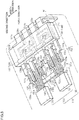
- the sensor unit 110 will be described. As illustrated in FIGS. 3 to 5 , the sensor unit 110 has a circuit member 120 and a sensor element 130 connected to the circuit member 120.
- the sensor element 130 has a rectangular parallelepiped shape.
- a magnetism detection element such as a Hall element, for example, is adopted as the sensor element 130.
- the sensor element 130 is provided with a first sensor element 131 and a second sensor element 132 provided redundantly.
- the first sensor element 131 and the second sensor element 132 are disposed side by side with each other in a direction (hereinafter referred to as a "width direction") that is orthogonal to the direction in which the second magnetism collection portion holder 90 extends.
- the first magnetism collection ring 41 is provided with two first magnetism collection portions 41b.
- the second magnetism collection ring 42 is provided with two second magnetism collection portions 42b.
- the first magnetism collection portions 41b are exposed at an end portion of the first magnetism collection portion holder 70 on the first ring portion holder 60 side.
- the second magnetism collection portions 42b are exposed at an end portion of the second magnetism collection portion holder 90 on the second ring portion holder 80 side.
- the first sensor element 131 and the second sensor element 132 are disposed between the first magnetism collection portions 41b and the second magnetism collection portions 42b with the first holder 51 and the second holder 52 assembled to each other.
- the first sensor element 131 has three terminals, namely a first power source terminal 131a, a first ground terminal 131b, and a first signal terminal 131c, which are arranged in this order in the direction (hereinafter referred to as a "first direction") from the second sensor element 132 toward the first sensor element 131.
- the first power source terminal 131a, the first ground terminal 131b, and the first signal terminal 131c extend toward the respective distal ends thereof in the direction in which the second magnetism collection portion holder 90 extends with the first sensor element 131 assembled to the second holder 52.
- the second sensor element 132 has three terminals, namely a second power source terminal 132a, a second ground terminal 132b, and a second signal terminal 132c, which are arranged in this order in the direction (hereinafter referred to as a "second direction") from the first sensor element 131 toward the second sensor element 132.
- the second power source terminal 132a, the second ground terminal 132b, and the second signal terminal 132c extend toward the respective distal ends thereof in the direction in which the second magnetism collection portion holder 90 extends with the second sensor element 132 assembled to the second holder 52.
- the circuit member 120 has a plate-shaped conductor portion 121 that is energizable and an electronic component 140.
- the conductor portion 121 is a bus bar constituted of a metal material.
- the conductor portion 121 of the circuit member 120 has six conductor portions, namely a first conductor portion 122, a second conductor portion 123, a third conductor portion 124, a fourth conductor portion 125, a fifth conductor portion 126, and a sixth conductor portion 127, which are arranged in this order in the second direction.
- the first conductor portion 122, the second conductor portion 123, the third conductor portion 124, the fourth conductor portion 125, the fifth conductor portion 126, and the sixth conductor portion 127 are disposed side by side with a clearance therebetween in the width direction.
- the first conductor portion 122 has a first terminal connection portion 122a, a first intermediate portion 122b, and a first external wiring connection portion 122c, which are arranged in this order toward the distal end in the direction in which the second magnetism collection portion holder 90 extends.
- the first conductor portion 122 has a crank shape as a whole.
- the first signal terminal 131c of the first sensor element 131 is electrically connected to the first terminal connection portion 122a by soldering, an adhesive, or the like.
- the first intermediate portion 122b is continuous with the first terminal connection portion 122a so as to be closer to the first direction than the first terminal connection portion 122a.
- the first external wiring connection portion 122c is continuous with the first intermediate portion 122b so as to be closer to the second direction than the first terminal connection portion 122a.
- the first external wiring connection portion 122c is formed to be bent at the distal end portion thereof in the direction in which the second magnetism collection portion holder 90 extends in order to extend in the direction away from the first magnetism collection portion holder 70.
- the second conductor portion 123 has a stepped portion 123d, a second terminal connection portion 123a, and a second intermediate portion 123b, which are arranged in this order toward the distal end in the direction in which the second magnetism collection portion holder 90 extends.
- the first ground terminal 131b of the first sensor element 131 is electrically connected to the second terminal connection portion 123a by soldering, an adhesive, or the like.
- the second intermediate portion 123b is continuous with the second terminal connection portion 123a, and is widened in the width direction.
- the stepped portion 123d is disposed away from the first magnetism collection portion holder 70 with respect to the second terminal connection portion 123a and the first sensor element 131.
- the stepped portion 123d has a rectangular plate shape.
- the longitudinal direction of the stepped portion 123d coincides with the width direction.
- An end portion of the stepped portion 123d in the first direction is bent to be continuous with the second terminal connection portion 123a.
- the third conductor portion 124 has a third terminal connection portion 124a, a third intermediate portion 124b, and a third external wiring connection portion 124c, which are arranged in this order toward the distal end in the direction in which the second magnetism collection portion holder 90 extends.
- the fourth conductor portion 125 has a fourth terminal connection portion 125a.
- the third conductor portion 124 and the fourth conductor portion 125 are disposed on the distal end side, in the direction in which the second magnetism collection portion holder 90 extends, with respect to the stepped portion 123d of the second conductor portion 123.
- the third terminal connection portion 124a and the fourth terminal connection portion 125a have a generally rectangular shape.
- the third intermediate portion 124b is continuous with the third terminal connection portion 124a and the fourth terminal connection portion 125a with the third terminal connection portion 124a and the fourth terminal connection portion 125a located away from each other in the width direction.
- the first power source terminal 131a of the first sensor element 131 is electrically connected to the third terminal connection portion 124a by soldering, an adhesive, or the like.
- the second power source terminal 132a of the second sensor element 132 is electrically connected to the fourth terminal connection portion 125a by soldering, an adhesive, or the like.
- the width of the third intermediate portion 124b in the width direction is set to be smaller in the width direction than the distance between an end portion of the third terminal connection portion 124a close to the first direction and an end portion of the fourth terminal connection portion 125a close to the second direction.
- the third conductor portion 124 and the fourth conductor portion 125 have a notched portion 124d surrounded by a surface of the third terminal connection portion 124a close to the second direction, a surface of the fourth terminal connection portion 125a close to the first direction, and a surface of the third intermediate portion 124b on the second ring portion holder 80 side.
- the notched portion 124d is formed in a two-stage notched shape in which the notch is narrowed in the width direction toward the distal end in the direction in which the second magnetism collection portion holder 90 extends.
- the third external wiring connection portion 124c is continuous with the third intermediate portion 124b so as to be at about the same position as the third terminal connection portion 124a in the width direction.
- the third external wiring connection portion 124c is formed to be bent at the distal end portion thereof in the direction in which the second magnetism collection portion holder 90 extends in order to extend in the direction away from the first magnetism collection portion holder 70.
- the fifth conductor portion 126 has a fifth terminal connection portion 126a, a fifth intermediate portion 126b, and a fifth external wiring connection portion 126c, which are arranged in this order toward the distal end in the direction in which the second magnetism collection portion holder 90 extends.
- the fifth conductor portion 126 has a crank shape as a whole.
- the second ground terminal 132b of the second sensor element 132 is electrically connected to the fifth terminal connection portion 126a by soldering, an adhesive, or the like.
- An end portion of the stepped portion 123d in the second direction is bent to be continuous with the fifth terminal connection portion 126a.
- the stepped portion 123d is disposed away from the first magnetism collection portion holder 70 with respect to the fifth terminal connection portion 126a and the second sensor element 132.
- the fifth intermediate portion 126b is continuous with the fifth terminal connection portion 126a, and is widened in the width direction.
- the fifth external wiring connection portion 126c is continuous with the fifth intermediate portion 126b so as to be closer to the first direction than the fifth terminal connection portion 126a.
- the fifth external wiring connection portion 126c is formed to be bent at the distal end portion thereof in the direction in which the second magnetism collection portion holder 90 extends in order to extend in the direction away from the first magnetism collection portion holder 70.
- the sixth conductor portion 127 has a sixth terminal connection portion 127a, a sixth intermediate portion 127b, and a sixth external wiring connection portion 127c, which are arranged in this order toward the distal end in the direction in which the second magnetism collection portion holder 90 extends.
- the sixth conductor portion 127 has a crank shape as a whole.
- the second signal terminal 132c of the second sensor element 132 is electrically connected to the sixth terminal connection portion 127a by soldering, an adhesive, or the like.
- the sixth intermediate portion 127b is continuous with the sixth terminal connection portion 127a so as to be closer to the second direction than the sixth terminal connection portion 127a.
- the sixth external wiring connection portion 127c is continuous with the sixth intermediate portion 127b so as to be closer to the first direction than the sixth intermediate portion 127b.
- the sixth external wiring connection portion 127c is formed to be bent at the distal end portion thereof in the direction in which the second magnetism collection portion holder 90 extends in order to extend in the direction away from the first magnetism collection portion holder 70.
- four external wiring connection portions namely the first external wiring connection portion 122c, the third external wiring connection portion 124c, the fifth external wiring connection portion 126c, and the sixth external wiring connection portion 127c, are arranged in this order in the second direction at the distal end portion of the conductor portion 121 in the direction in which the second magnetism collection portion holder 90 extends, and disposed side by side with a clearance therebetween in the width direction.
- the sensor unit 110 has a cover portion 111 that couples the first conductor portion 122, the second conductor portion 123, the third conductor portion 124, the fourth conductor portion 125, the fifth conductor portion 126, and the sixth conductor portion 127.
- the cover portion 111 is constituted of a synthetic resin.
- the cover portion 111 has a rectangular parallelepiped shape so as to cover the first intermediate portion 122b, the second intermediate portion 123b, the third intermediate portion 124b, the fifth intermediate portion 126b, and the sixth intermediate portion 127b.
- the longitudinal direction of the cover portion 111 corresponds to the width direction.
- the electronic component 140 is provided inside the cover portion 111.
- a capacitor etc. is adopted as the electronic component 140.
- the electronic component 140 has a first electronic component 141, a second electronic component 142, a third electronic component 143, and a fourth electronic component 144, which are arranged in this order in the second direction.
- the first electronic component 141 is disposed so as to extend between the first intermediate portion 122b of the first conductor portion 122 and the second intermediate portion 123b of the second conductor portion 123.
- the first electronic component 141 is electrically connected to the first intermediate portion 122b and the second intermediate portion 123b.
- the second electronic component 142 is disposed so as to extend between the second intermediate portion 123b of the second conductor portion 123 and the third intermediate portion 124b of the third conductor portion 124.
- the second electronic component 142 is electrically connected to the second intermediate portion 123b and the third intermediate portion 124b.
- the third electronic component 143 is disposed so as to extend between the third intermediate portion 124b of the third conductor portion 124 and the fifth intermediate portion 126b of the fifth conductor portion 126.
- the third electronic component 143 is electrically connected to the third intermediate portion 124b and the fifth intermediate portion 126b.
- the fourth electronic component 144 is disposed so as to extend between the fifth intermediate portion 126b of the fifth conductor portion 126 and the sixth intermediate portion 127b of the sixth conductor portion 127.
- the fourth electronic component 144 is electrically connected to the fifth intermediate portion 126b of the fifth conductor portion 126 and the sixth intermediate portion 127b.
- the first electronic component 141, the second electronic component 142, the third electronic component 143, and the fourth electronic component 144 are covered by the cover portion 111.
- the circuit member 120 can be divided into two, namely a first circuit member 120a connected to the first sensor element 131 and a second circuit member 120b connected to the second sensor element 132.
- the first circuit member 120a is constituted from the first conductor portion 122, the second conductor portion 123, the third terminal connection portion 124a, the third intermediate portion 124b, and the third external wiring connection portion 124c of the third conductor portion 124, the first electronic component 141, the second electronic component 142, and the cover portion 111.
- the second circuit member 120b is constituted from the fourth conductor portion 125, the fifth conductor portion 126, the sixth conductor portion 127, the third intermediate portion 124b and the third external wiring connection portion 124c of the third conductor portion 124, the third electronic component 143, the fourth electronic component 144, and the cover portion 111.
- the second magnetism collection portion holder 90 will be described. As illustrated in FIGS. 2 , 4 , and 5 , the sensor unit 110 is placed on the placement portion 93.
- the side wall 94 of the second magnetism collection portion holder 90 separates the internal space, which is formed between the first magnetism collection portion holder 70 and the second magnetism collection portion holder 90, and the outside from each other.
- the side wall 94 has long side walls 94a and a short side wall 94b corresponding to the rectangular shape of the second magnetism collection portion holder 90.
- the long side walls 94a are provided at end portions of the second holder body portion 91 in the width direction. The long side walls 94a face each other.
- the short side wall 94b is provided at the distal end portion of the second holder body portion 91 in the direction in which the second magnetism collection portion holder 90 extends.
- the long side walls 94a is thicker than the short side wall 94b.
- Holes 95 that extend in the axial direction X are formed at respective end portions of the long side walls 94a on the second ring portion holder 80 side. When seen in the axial direction X, the center of the thickness of the long side wall 94a in the width direction is positioned on the outer side with respect to the center of the hole 95 in the width direction.
- the placement portion 93 has a first recessed portion 93b and a second recessed portion 93c formed to be recessed with respect to a base surface 93a formed to be recessed with respect to a surface of the second holder body portion 91 on the first magnetism collection portion holder 70 side.
- the first recessed portion 93b and the second recessed portion 93c have a rectangular shape when seen in the axial direction X.
- the longitudinal direction of the first recessed portion 93b and the second recessed portion 93c coincides with the width direction.
- the length, in the width direction, of the first recessed portion 93b is set to be shorter than the length, in the width direction, of the second recessed portion 93c.
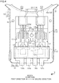
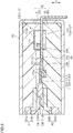
- the second magnetism collection portion holder 90 has a suppression portion 150 that projects from the second holder body portion 91 (inside) toward the first holder 51.
- the suppression portion 150 has a circular column shape.
- the suppression portion 150 projects toward the first holder 51 with respect to the side wall 94.
- the distal end surface of the suppression portion 150 abuts against the inner surface of the first holder body portion 71 with the first holder 51 and the second holder 52 assembled to each other with the sensor unit 110 interposed therebetween.
- the suppression portion 150 is positioned between the third terminal connection portion 124a and the fourth terminal connection portion 125a in the width direction, and between the third intermediate portion 124b and the stepped portion 123d in the direction in which the second magnetism collection portion holder 90 extends, with the sensor unit 110 assembled to the second magnetism collection portion holder 90.
- the suppression portion 150 is disposed with a clearance from the third terminal connection portion 124a, the fourth terminal connection portion 125a, the third intermediate portion 124b, and the stepped portion 123d.
- the first magnetism collection portion holder 70 has a side wall 74 that separates the internal space and the outside from each other, as with the side wall 94 of the second magnetism collection portion holder 90.
- the side wall 74 has long side walls 74a and a short side wall 74b.
- the first holder 51 and the second holder 52 are assembled to each other with the top surfaces of the long side walls 94a of the second magnetism collection portion holder 90 in surface contact with ceiling surfaces connecting to the long side walls 74a of the first magnetism collection portion holder 70 and with the top surface of the short side wall 94b of the second magnetism collection portion holder 90 in surface contact with a ceiling surface connecting to the short side wall 74b of the first magnetism collection portion holder 70.
- the first magnetism collection portion holder 70 has a projection portion 151 that projects from the first holder body portion 71 (inside) toward the second holder 52.
- the projection portion 151 is disposed on the distal end side, in the direction in which the second magnetism collection portion holder 90 extends, with respect to the suppression portion 150.
- the projection portion 151 faces a portion of the third intermediate portion 124b of the third conductor portion 124 that is not covered by the cover portion 111.
- the projection length of the projection portion 151 from the first holder body portion 71 is set to be shorter than the projection length of the suppression portion 150 from the second holder body portion 91.
- a clearance is formed between the projection portion 151 and the third intermediate portion 124b with the first holder 51 and the second holder 52 assembled to each other with the sensor unit 110 interposed therebetween.
- a clearance is formed between the cover portion 111 and the first holder body portion 71 with the first holder 51 and the second holder 52 assembled to each other with the sensor unit 110 interposed therebetween.
- the first holder 51 and the second holder 52 are assembled to each other with the sensor unit 110 interposed therebetween.
- the first fitting projecting portions 63 of the first ring portion holder 60 are fitted with the first fitting recessed portions 83 of the second ring portion holder 80.
- the second fitting projecting portions 72 of the first magnetism collection portion holder 70 are fitted with the second fitting recessed portions 92 of the second magnetism collection portion holder 90. Consequently, the first holder 51 and the second holder 52 are completely assembled to each other. This assembly is covered by a housing 160 to complete the torque sensor 1.
- An injection molding method for the housing 160 will be described.
- An assembly in which the first holder 51 and the second holder 52 are assembled to each other with the sensor unit 110 interposed therebetween is housed in a die (not illustrated) to be clamped in the die.
- a molten resin that is melted by being heated is injected into the die from an injection device (not illustrated), and a molding pressure, which is the pressure of the molten resin charged into the die, is kept constant. Consequently, air bubbles etc. that remain in the molten resin are removed.
- the molten resin injected into the die is cooled, the molten resin is solidified so as to cover the assembled holder 50. Consequently, the housing 160 is formed by injection molding.
- the positional relationship of the permanent magnet 20 with the first magnetic yoke 31 and with the second magnetic yoke 32 is varied, and therefore magnetism collected by the first magnetic yoke 31 and the second magnetic yoke 32 is varied. Consequently, magnetic flux that passes between the first magnetism collection portions 41b and the second magnetism collection portions 42b is varied, and therefore the intensity of magnetism applied to the sensor element 130 is varied.
- the intensity of magnetism applied to the sensor element 130 is varied in accordance with the torsional angle of the torsion bar 13.
- the torsional angle of the torsion bar 13 can be computed on the basis of a detection signal output from the sensor element 130, and therefore torque applied to the rotary shaft 10 can be computed on the basis of the torsional angle of the torsion bar 13.
- a torque sensor according to a second embodiment will be described. Differences from the first embodiment will be mainly described.
- the second magnetism collection portion holder 90 has a suppression portion 150a that projects from the second holder body portion 91 toward the first holder 51.
- the suppression portion 150a has a shape in which two rectangular columns in different shapes are molded integrally with each other.
- the suppression portion 150a has a first rectangular column portion 150b and a second rectangular column portion 150c.
- the second rectangular column portion 150c is positioned on the distal end side, in the direction in which the second magnetism collection portion holder 90 extends, with respect to the first rectangular column portion 150b.
- the projection length, in the axial direction X, of the first rectangular column portion 150b from the second holder body portion 91 is set to be equal to the projection length, in the axial direction X, of the second rectangular column portion 150c from the second holder body portion 91.
- the second rectangular column portion 150c is formed to be smaller in the width direction and smaller in the direction in which the second magnetism collection portion holder 90 extends than the first rectangular column portion 150b.
- the suppression portion 150a is disposed between the third terminal connection portion 124a and the fourth terminal connection portion 125a.
- the first rectangular column portion 150b abuts against the third terminal connection portion 124a and the fourth terminal connection portion 125a at a wide portion between the third terminal connection portion 124a and the fourth terminal connection portion 125a.
- the second rectangular column portion 150c abuts against the third terminal connection portion 124a and the fourth terminal connection portion 125a at a portion that is narrow in the width direction between the third terminal connection portion 124a and the fourth terminal connection portion 125a.
- the suppression portion 150a contacts the third terminal connection portion 124a and the fourth terminal connection portion 125a in the width direction with the sensor unit 110 assembled to the second magnetism collection portion holder 90.
- the suppression portion 150a is disposed between the third terminal connection portion 124a and the fourth terminal connection portion 125a, that is, between the first circuit member 120a and the second circuit member 120b. Therefore, the position of assembly of the circuit member 120 and the sensor element 130 can be prescribed with reference to the suppression portion 150a when the circuit member 120 and the sensor element 130 are assembled to the second holder 52. This allows the circuit member 120 and the sensor element 130 to be positioned with respect to the second holder 52 using the suppression portion 150a.
- the embodiments may be modified as follows. The following other embodiments may be combined with each other as long as the embodiments do not technically contradict with each other.
- the thickness of the long side walls 94a may be set to be equal to the thickness of the short side wall 94b.
- the thickness of the long side walls 94a may be set to be smaller than the thickness of the short side wall 94b.
- the longitudinal direction of the first magnetism collection portion holder 70 may be orthogonal to the direction in which the first magnetism collection portions 41b extend.
- the longitudinal direction of the second magnetism collection portion holder 90 may be orthogonal to the direction in which the second magnetism collection portions 42b extend.
- the projection length of the suppression portion 150 may be equal to the projection length of the projection portion 151.
- the projection length of the suppression portion 150a may be equal to the projection length of the projection portion 151.
- the projection portion 151 may not be provided.
- the sensor element 130 includes the first sensor element 131 and the second sensor element 132 that are provided redundantly. However, only the first sensor element 131 may be provided as the sensor element 130. Alternatively, the sensor element 130 may be provided with three or more sensor elements.
- the suppression portion 150 is positioned between the first circuit member 120a and the second circuit member 120b, that is, between the third terminal connection portion 124a and the fourth terminal connection portion 125a in the width direction, and between the third intermediate portion 124b and the stepped portion 123d in the direction in which the second magnetism collection portion holder 90 extends.
- the present invention is not limited thereto.
- the suppression portion 150 may be provided at a portion of the placement portion 93 of the second magnetism collection portion holder 90 on the outer side of the circuit member 120.
- the suppression portion 150a is positioned between the first circuit member 120a and the second circuit member 120b, that is, between the third terminal connection portion 124a and the fourth terminal connection portion 125a in the width direction, and between the third intermediate portion 124b and the stepped portion 123d in the direction in which the second magnetism collection portion holder 90 extends.
- the present invention is not limited thereto.
- the suppression portion 150a may be provided at a portion of the placement portion 93 of the second magnetism collection portion holder 90 on the outer side of the circuit member 120.
- the suppression portion 150 projects from the second holder body portion 91 toward the first holder 51.
- the present invention is not limited thereto.
- the suppression portion 150 may project from the first holder body portion 71 toward the second holder 52.
- the suppression portion 150a may project from the first holder body portion 71 toward the second holder 52.
- a clearance may be formed in the axial direction X between the suppression portion 150 and the first holder body portion 71 with the first holder 51 and the second holder 52 assembled to each other with the sensor unit 110 interposed therebetween.
- the holder 50 is constituted from the first holder 51 and the second holder 52. However, the holder 50 may be constituted from three or more holders.
- the suppression portion 150 is provided integrally with the second holder body portion 91. However, the suppression portion 150 may be provided separately therefrom.
- the suppression portion 150a may be provided separately from the second holder body portion 91.
- the suppression portion 150 may have a polygonal column shape such as a rectangular column shape, for example.
- the suppression portion 150 may be provided so as to contact the third terminal connection portion 124a and the fourth terminal connection portion 125a in the width direction.
- the suppression portion 150a may be disposed with a clearance from the third terminal connection portion 124a and the fourth terminal connection portion 125a. While a hall element is adopted as the sensor element 130, a magnetoresistance element may be adopted.
- the sensor device is embodied as the torque sensor 1 that detects torque
- the sensor device may be embodied as a rotational angle detection device that detects the rotational angle of the rotary shaft 10, for example.
Landscapes
- Physics & Mathematics (AREA)
- Electromagnetism (AREA)
- General Physics & Mathematics (AREA)
- Engineering & Computer Science (AREA)
- Microelectronics & Electronic Packaging (AREA)
- Power Steering Mechanism (AREA)
- Measuring Magnetic Variables (AREA)
Abstract
Description
- The present invention relates to a sensor device.
- Japanese Patent Application Publication No.
2015-191995 JP 2015-191995 A - In the device according to
JP 2015-191995 A - It is an object of the present invention to provide a sensor device that can suppress deformation of a holder due to a molding pressure applied during injection molding of a housing.
- An aspect of the present invention provides a sensor device including: a holder that surrounds a circuit member, to which an electronic component is electrically connected, and a sensor element electrically connected to the circuit member; and a housing formed by injection molding so as to cover the holder. In the sensor device, a suppression portion is provided inside the holder. The suppression portion extends in a column shape so as to connect between inner portions of the holder in a direction of deformation of the holder due to a molding pressure during the injection molding in order to suppress the deformation.
- With the configuration described above, in the case where the molding pressure during the injection molding of the housing acts on the holder, the suppression portion that is provided inside the holder engages to suppress deformation of the holder due to the molding pressure during the injection molding. This suppresses contact of the deformed holder with the circuit member. Therefore, it is possible to suppress separation of the electronic component from the circuit member due to such contact, and to suppress electrical connection between the circuit member and the sensor element becoming poor.
- In the sensor device according to a different aspect of the present invention, the holder may be constituted from at least a first holder and a second holder, and surround the circuit member and the sensor element between the first holder and the second holder; the first holder may have a first holder body portion; and the second holder may have a second holder body portion that includes a placement portion, on which the circuit member and the sensor element are placed, and that faces the first holder body portion, and the suppression portion that projects from the second holder body portion toward the first holder body portion.
- With the configuration described above, in the case where the molding pressure during the injection molding of the housing acts on the holder, the suppression portion that is provided on the second holder body portion of the second holder engages with the first holder body portion. Therefore, deformation of the first holder body portion and the second holder body portion can be suppressed. Thus, the circuit member and the sensor element that are placed on the placement portion of the second holder can be protected. The suppression portion is provided on the second holder body portion, on which the circuit member and the sensor element are placed. In this case, it is not necessary to pay attention to avoid contact of the suppression portion with the circuit member and the sensor element during assembly of the first holder and the second holder. This facilitates assembly between the first holder and the second holder.
- In the sensor device according to a different aspect of the present invention, the sensor element may include a first sensor element and a second sensor element; the circuit member may include a first circuit member electrically connected to the first sensor element and a second circuit member electrically connected to the second sensor element; and the suppression portion may be disposed between the first circuit member and the second circuit member with a clearance from the first circuit member and the second circuit member.
- With the configuration described above, the suppression portion is disposed between the first circuit member and the second circuit member. Therefore, the arrangement of the suppression portion is suitable for suppressing contact of the first holder body portion with the first circuit member and the second circuit member. Interference between the sensor element and the circuit member and the suppression portion is suppressed, since the suppression portion is disposed with a clearance from the first circuit member and the second circuit member, when the sensor element and the circuit member are assembled to the second holder.
- In the sensor device according to a different aspect of the present invention, the sensor element may include a first sensor element and a second sensor element; the circuit member may include a first circuit member electrically connected to the first sensor element and a second circuit member electrically connected to the second sensor element; and the suppression portion may be disposed between the first circuit member and the second circuit member in abutment with the first circuit member and the second circuit member.
- With the configuration described above, the suppression portion is disposed between the first circuit member and the second circuit member. Therefore, the arrangement of the suppression portion is suitable for suppressing contact of the first holder body portion with the first circuit member and the second circuit member. The position of assembly of the circuit member and the sensor element can be prescribed with reference to the suppression portion when the circuit member and the sensor element are assembled to the holder. Therefore, the circuit member and the sensor element can be positioned with respect to the holder using the suppression portion.
- In the sensor device according to a different aspect of the present invention, the circuit member may include the electronic component and a conductor portion that is energizable; the first holder may have a projection portion that projects from the first holder body portion toward the second holder and that faces the conductor portion; and a projection length of the suppression portion may be set to be longer than a projection length of the projection portion. With the configuration described above, the molding pressure during the injection molding of the housing mainly acts on the suppression portion of the second holder, which suppresses application of the molding pressure to the circuit member.
- The sensor device according to a different aspect of the present invention may further include a permanent magnet attached to a first shaft and magnetized in a circumferential direction, a magnetic yoke that is fixed to a second shaft coupled to the first shaft via a coupling shaft and is disposed in a magnetic field formed by the permanent magnet, and a magnetism collection ring disposed so as to surround the magnetic yoke and configured to collect magnetic flux of the magnetic yoke; the magnetism collection ring may have an annular ring portion that surrounds the magnetic yoke and a magnetism collection portion that extends toward a radially outer side of the ring portion; the holder may have a magnetism collection portion holder that surrounds the magnetism collection portion, the sensor element, and the circuit member and that has a rectangular shape; a longitudinal direction of the magnetism collection portion holder may coincide with a direction in which the magnetism collection portion extends, and a short-length direction of the magnetism collection portion holder may coincide with a direction that is orthogonal to the direction in which the magnetism collection portion extends; and the magnetism collection portion holder may be provided with a side wall that separates an inside and an outside of the magnetism collection portion holder, and a long side wall of the side wall may be set to be thicker than a short side wall of the side wall.
- Since the magnetism collection portion holder has a rectangular shape, a portion of the side wall that extends in the longitudinal direction and that is large in area, that is, the long side wall, is easily deformable. Therefore, also in the case where the molding pressure during the injection molding of the housing acts on the holder, similarly, the molding pressure acts more significantly in the direction in which the magnetism collection portion extends. In the configuration described above, the thickness of the side wall of the magnetism collection portion holder is determined such that the long side wall, on which the molding pressure acts significantly, is thicker than the short side wall. Therefore, the effect of the molding pressure during the injection molding of the housing can be suitably suppressed by the magnetism collection portion holder.
- The foregoing and further features and advantages of the invention will become apparent from the following description of example embodiments with reference to the accompanying drawings, wherein like numerals are used to represent like elements and wherein:
-
FIG. 1 is an exploded perspective view illustrating the configuration of a torque sensor according to a first embodiment; -
FIG. 2 is an exploded perspective view of a magnetism collection ring, a holder, a sensor unit, and a magnetic shield of the torque sensor according to the first embodiment; -
FIG. 3 is a perspective view of a circuit member and a sensor element of the torque sensor according to the first embodiment; -
FIG. 4 is a top view of a second magnetism collection portion holder of the torque sensor according to the first embodiment; -
FIG. 5 is a sectional view of a magnetism collection portion holder of the torque sensor according to the first embodiment; and -
FIG. 6 is a top view of a magnetism collection portion holder of a torque sensor according to a second embodiment. - A torque sensor as a first embodiment of a sensor device according to the present invention will be described below. As illustrated in
FIGS. 1 and2 , atorque sensor 1 includes atorsion bar 13, a cylindricalpermanent magnet 20, a cylindricalmagnetic yoke 30, a cylindricalmagnetism collection ring 40 disposed so as to surround themagnetic yoke 30, aholder 50 that holds themagnetism collection ring 40, amagnetic shield 100 that covers the outer periphery of theholder 50, and asensor unit 110. Thetorque sensor 1 detects torque applied to arotary shaft 10 such as a steering shaft. - The
rotary shaft 10 has aninput shaft 11 that serves as a first shaft, anoutput shaft 12 that serves as a second shaft, and thetorsion bar 13 that serves as a coupling shaft. Thetorsion bar 13 is disposed between theinput shaft 11 and theoutput shaft 12. Theinput shaft 11 and theoutput shaft 12 are coupled to each other on the same axis via thetorsion bar 13. - The
permanent magnet 20 is coupled to theinput shaft 11. Thepermanent magnet 20 has acylindrical holding portion 21 and amultipole magnet 22. Theholding portion 21 is externally fitted with an end portion of theinput shaft 11 on theoutput shaft 12 side. Theholding portion 21 is attached so as to be rotatable together with theinput shaft 11. Themultipole magnet 22 is attached to the outer peripheral surface of theholding portion 21. Themultipole magnet 22 is structured such that N and S magnetic poles are disposed alternately in the circumferential direction of theholding portion 21. - The
magnetic yoke 30 is coupled to theoutput shaft 12. Themagnetic yoke 30 has an annular firstmagnetic yoke 31 and an annular secondmagnetic yoke 32. The firstmagnetic yoke 31 and the secondmagnetic yoke 32 are disposed coaxially with theoutput shaft 12, and fixed so as to be rotatable together with theoutput shaft 12. The firstmagnetic yoke 31 and the secondmagnetic yoke 32 are disposed around themultipole magnet 22 via a predetermined clearance therefrom. The firstmagnetic yoke 31 and the secondmagnetic yoke 32 are disposed in a magnetic field formed by themultipole magnet 22. The firstmagnetic yoke 31 and the secondmagnetic yoke 32 are disposed so as to face each other with a predetermined clearance therebetween in an axial direction X. The axial direction X is the axial direction of theoutput shaft 12, and is parallel to the axis of theinput shaft 11 and theoutput shaft 12. The firstmagnetic yoke 31 has an annular firstannular portion 31a and a plurality offirst lug portions 31b that extend toward the secondmagnetic yoke 32 from the inner peripheral surface of the firstannular portion 31a. Thefirst lug portions 31b are disposed at equal intervals in the circumferential direction on the inner peripheral surface of the firstannular portion 31a. The secondmagnetic yoke 32 has an annular secondannular portion 32a and a plurality ofsecond lug portions 32b that extend toward the firstmagnetic yoke 31 from the inner peripheral surface of the secondannular portion 32a. Thesecond lug portions 32b are disposed at equal intervals in the circumferential direction on the inner peripheral surface of the secondannular portion 32a. The firstmagnetic yoke 31 and the secondmagnetic yoke 32 are molded in asynthetic resin body 33 with thefirst lug portions 31b and thesecond lug portions 32b displaced from each other by a constant distance in the circumferential direction. The inner peripheral surfaces of the firstmagnetic yoke 31 and the secondmagnetic yoke 32 are exposed from thesynthetic resin body 33. The outer peripheral surfaces of the firstannular portion 31a and the secondannular portion 32a are exposed from thesynthetic resin body 33. The firstmagnetic yoke 31 and the secondmagnetic yoke 32 are constituted of a magnetic material. - In a neutral state in which the
torsion bar 13 between theinput shaft 11 and theoutput shaft 12 is not twisted, the distal ends of thefirst lug portions 31b of the firstmagnetic yoke 31 and the distal ends of thesecond lug portions 32b of the secondmagnetic yoke 32 point to the boundary between the N poles and the S poles of themultipole magnet 22 of thepermanent magnet 20. - The
magnetism collection ring 40 has an annular firstmagnetism collection ring 41 that guides and collects magnetic flux of the firstmagnetic yoke 31, and an annular secondmagnetism collection ring 42 that guides and collects magnetic flux of the secondmagnetic yoke 32. The firstmagnetism collection ring 41 and the secondmagnetism collection ring 42 are disposed side by side with a predetermined clearance therebetween in the axial direction X. The firstmagnetism collection ring 41 and the secondmagnetism collection ring 42 are constituted of a magnetic material. - The first
magnetism collection ring 41 has afirst ring portion 41a disposed at the outer periphery of the firstmagnetic yoke 31 with a predetermined clearance therefrom so as to surround the firstmagnetic yoke 31, and firstmagnetism collection portions 41b that extend toward the radially outer side of thefirst ring portion 41a. - The second
magnetism collection ring 42 has asecond ring portion 42a disposed at the outer periphery of the secondmagnetic yoke 32 with a predetermined clearance therefrom so as to surround the secondmagnetic yoke 32, and secondmagnetism collection portions 42b that extend toward the radially outer side of thesecond ring portion 42a. - When the first
magnetism collection ring 41 is disposed at the outer periphery of the firstmagnetic yoke 31 and the secondmagnetism collection ring 42 is disposed at the outer periphery of the secondmagnetic yoke 32, the firstmagnetism collection portions 41b and the secondmagnetism collection portions 42b are disposed so as to face each other with a predetermined clearance therebetween in the axial direction X. - The
holder 50 has afirst holder 51 that holds the firstmagnetism collection ring 41, and asecond holder 52 that holds the secondmagnetism collection ring 42. Thefirst holder 51 and thesecond holder 52 are disposed side by side in the axial direction X. Theholder 50 is constituted by assembling thefirst holder 51 and thesecond holder 52 to each other. - The
first holder 51 has a firstring portion holder 60 that surrounds and holds thefirst ring portion 41a, and a first magnetismcollection portion holder 70 that surrounds and holds the firstmagnetism collection portions 41b. The first magnetismcollection portion holder 70 extends radially outward from the firstring portion holder 60. The firstring portion holder 60 and the first magnetismcollection portion holder 70 are molded integrally with each other. The firstring portion holder 60 and the first magnetismcollection portion holder 70 are constituted of a synthetic resin. - The first
ring portion holder 60 has a generally cylindrical shape so as to surround thefirst ring portion 41a. The firstring portion holder 60 has a firstcircumferential surface portion 61. The outer peripheral surface of the firstcircumferential surface portion 61 is a circumferential surface. Afirst flange portion 62 that projects radially outward is provided on the outer side surface of the firstcircumferential surface portion 61. Thefirst flange portion 62 is provided at a portion of the outer side surface of the firstcircumferential surface portion 61 on the opposite side from thesecond holder 52. The firstring portion holder 60 is provided with four firstfitting projecting portions 63 that project from a surface of the firstring portion holder 60 on thesecond holder 52 side toward thesecond holder 52. The firstfitting projecting portions 63 are provided at predetermined intervals from each other in the circumferential direction of the firstring portion holder 60. The firstfitting projecting portions 63 serve as lugs for snap fitting. The outer side surface of the firstring portion holder 60 is provided with twofirst holding portions 64 that project radially outward and in which recesses are formed. Thefirst holding portions 64 are provided at positions that are proximate to the first magnetismcollection portion holder 70 in the circumferential direction of the firstring portion holder 60. - The first magnetism
collection portion holder 70 has a rectangular plate shape. The first magnetismcollection portion holder 70 is connected to a portion of the outer peripheral surface of the firstring portion holder 60 on thesecond holder 52 side. The longitudinal direction of the first magnetismcollection portion holder 70 coincides with the direction in which the firstmagnetism collection portions 41b extend. The first magnetismcollection portion holder 70 has a firstholder body portion 71 that faces thesecond holder 52. A surface of the firstholder body portion 71 on the opposite side from thesecond holder 52 is positioned to be flush with a surface of the firstring portion holder 60 on the opposite side from thesecond holder 52. The thickness, in the axial direction X, of the firstholder body portion 71 of the first magnetismcollection portion holder 70 is set to be about the same as the thickness, in the axial direction X, of the firstcircumferential surface portion 61 of the firstring portion holder 60. The first magnetismcollection portion holder 70 is provided with secondfitting projecting portions 72 that project toward thesecond holder 52 with respect to a surface of the firstholder body portion 71 on thesecond holder 52 side. The secondfitting projecting portions 72 are provided on the distal end side of the firstholder body portion 71. The secondfitting projecting portions 72 are provided at both end portions of the firstholder body portion 71 in a direction that is orthogonal to the direction in which the first magnetismcollection portion holder 70 extends. The secondfitting projecting portions 72 serve as lugs for snap fitting. - The
second holder 52 has a secondring portion holder 80 that surrounds and holds thesecond ring portion 42a, and a second magnetismcollection portion holder 90 that surrounds and holds the secondmagnetism collection portions 42b. The second magnetismcollection portion holder 90 extends radially outward from the secondring portion holder 80. The secondring portion holder 80 and the second magnetismcollection portion holder 90 are molded integrally with each other. The secondring portion holder 80 and the second magnetismcollection portion holder 90 are constituted of a synthetic resin. - The second
ring portion holder 80 has a generally cylindrical shape so as to surround the secondmagnetism collection ring 42. The secondring portion holder 80 has a secondcircumferential surface portion 81. The outer peripheral surface of the second circumferential surface is a circumferential surface. Asecond flange portion 82 that projects radially outward is provided on the outer side surface of the secondcircumferential surface portion 81. Thesecond flange portion 82 is provided at a portion of the outer side surface of the secondcircumferential surface portion 81 on the opposite side from thefirst holder 51. Four first fitting recessed portions 83 are provided in the outer peripheral surface of the secondring portion holder 80. The first fitting recessed portions 83 are formed to be recessed over the entire region, in the axial direction, of the secondring portion holder 80. The first fitting recessed portions 83 are provided at predetermined intervals from each other in the circumferential direction of the secondring portion holder 80. The outer peripheral surface of the secondring portion holder 80 is provided with twosecond holding portions 84 that project radially outward and in which recesses are formed. Thesecond holding portions 84 are provided at positions that are proximate to the second magnetismcollection portion holder 90 in the circumferential direction of the secondring portion holder 80. - The
magnetic shield 100 is disposed on the outer circumferential side of the firstring portion holder 60 and the secondring portion holder 80 with thefirst holder 51 and thesecond holder 52 assembled to each other. Themagnetic shield 100 is formed in a C-shape in cross section. A material that can block magnetism such as metal, for example, is adopted for themagnetic shield 100. Themagnetic shield 100 abuts against thefirst flange portion 62 of the firstring portion holder 60 and thesecond flange portion 82 of the secondring portion holder 80 in the axial direction X. Both end portions, in the circumferential direction, of themagnetic shield 100 are inserted into thefirst holding portions 64 and thesecond holding portions 84 to be held. - The second magnetism
collection portion holder 90 has a rectangular plate shape. The second magnetismcollection portion holder 90 is connected to the outer peripheral surface of the secondring portion holder 80. The second magnetismcollection portion holder 90 is disposed so as to face the first magnetismcollection portion holder 70 in the axial direction X. The longitudinal direction of the second magnetismcollection portion holder 90 coincides with the direction in which the secondmagnetism collection portions 42b extend. The second magnetismcollection portion holder 90 has a secondholder body portion 91. A surface of the secondholder body portion 91 on the opposite side from thefirst holder 51 is positioned to be flush with a surface of the secondring portion holder 80 on the opposite side from the firstring portion holder 60. The thickness, in the axial direction X, of the secondholder body portion 91 of the second magnetismcollection portion holder 90 is set to be about the same as the thickness, in the axial direction X, of the secondcircumferential surface portion 81 of the secondring portion holder 80. The secondholder body portion 91 has second fitting recessedportions 92 to be fitted with the secondfitting projecting portions 72. The second fitting recessedportions 92 are positioned on the distal end side of the secondholder body portion 91, and provided at portions of the outer side surface of the secondholder body portion 91 on the opposite side from thefirst holder 51. The secondholder body portion 91 has aplacement portion 93 for placement of thesensor unit 110, and aside wall 94. Theplacement portion 93 is formed to be recessed with respect to theside wall 94. - The
sensor unit 110 will be described. As illustrated inFIGS. 3 to 5 , thesensor unit 110 has acircuit member 120 and asensor element 130 connected to thecircuit member 120. Thesensor element 130 has a rectangular parallelepiped shape. A magnetism detection element such as a Hall element, for example, is adopted as thesensor element 130. In the present embodiment, thesensor element 130 is provided with afirst sensor element 131 and asecond sensor element 132 provided redundantly. Thefirst sensor element 131 and thesecond sensor element 132 are disposed side by side with each other in a direction (hereinafter referred to as a "width direction") that is orthogonal to the direction in which the second magnetismcollection portion holder 90 extends. The firstmagnetism collection ring 41 is provided with two firstmagnetism collection portions 41b. The secondmagnetism collection ring 42 is provided with two secondmagnetism collection portions 42b. The firstmagnetism collection portions 41b are exposed at an end portion of the first magnetismcollection portion holder 70 on the firstring portion holder 60 side. The secondmagnetism collection portions 42b are exposed at an end portion of the second magnetismcollection portion holder 90 on the secondring portion holder 80 side. Thefirst sensor element 131 and thesecond sensor element 132 are disposed between the firstmagnetism collection portions 41b and the secondmagnetism collection portions 42b with thefirst holder 51 and thesecond holder 52 assembled to each other. Thefirst sensor element 131 has three terminals, namely a firstpower source terminal 131a, afirst ground terminal 131b, and afirst signal terminal 131c, which are arranged in this order in the direction (hereinafter referred to as a "first direction") from thesecond sensor element 132 toward thefirst sensor element 131. The firstpower source terminal 131a, thefirst ground terminal 131b, and thefirst signal terminal 131c extend toward the respective distal ends thereof in the direction in which the second magnetismcollection portion holder 90 extends with thefirst sensor element 131 assembled to thesecond holder 52. Thesecond sensor element 132 has three terminals, namely a secondpower source terminal 132a, asecond ground terminal 132b, and asecond signal terminal 132c, which are arranged in this order in the direction (hereinafter referred to as a "second direction") from thefirst sensor element 131 toward thesecond sensor element 132. The secondpower source terminal 132a, thesecond ground terminal 132b, and thesecond signal terminal 132c extend toward the respective distal ends thereof in the direction in which the second magnetismcollection portion holder 90 extends with thesecond sensor element 132 assembled to thesecond holder 52. - The
circuit member 120 has a plate-shapedconductor portion 121 that is energizable and anelectronic component 140. Theconductor portion 121 is a bus bar constituted of a metal material. Theconductor portion 121 of thecircuit member 120 has six conductor portions, namely afirst conductor portion 122, asecond conductor portion 123, athird conductor portion 124, afourth conductor portion 125, afifth conductor portion 126, and asixth conductor portion 127, which are arranged in this order in the second direction. Thefirst conductor portion 122, thesecond conductor portion 123, thethird conductor portion 124, thefourth conductor portion 125, thefifth conductor portion 126, and thesixth conductor portion 127 are disposed side by side with a clearance therebetween in the width direction. - The
first conductor portion 122 has a firstterminal connection portion 122a, a firstintermediate portion 122b, and a first externalwiring connection portion 122c, which are arranged in this order toward the distal end in the direction in which the second magnetismcollection portion holder 90 extends. Thefirst conductor portion 122 has a crank shape as a whole. Thefirst signal terminal 131c of thefirst sensor element 131 is electrically connected to the firstterminal connection portion 122a by soldering, an adhesive, or the like. The firstintermediate portion 122b is continuous with the firstterminal connection portion 122a so as to be closer to the first direction than the firstterminal connection portion 122a. The first externalwiring connection portion 122c is continuous with the firstintermediate portion 122b so as to be closer to the second direction than the firstterminal connection portion 122a. The first externalwiring connection portion 122c is formed to be bent at the distal end portion thereof in the direction in which the second magnetismcollection portion holder 90 extends in order to extend in the direction away from the first magnetismcollection portion holder 70. - The
second conductor portion 123 has a steppedportion 123d, a second terminal connection portion 123a, and a second intermediate portion 123b, which are arranged in this order toward the distal end in the direction in which the second magnetismcollection portion holder 90 extends. Thefirst ground terminal 131b of thefirst sensor element 131 is electrically connected to the second terminal connection portion 123a by soldering, an adhesive, or the like. The second intermediate portion 123b is continuous with the second terminal connection portion 123a, and is widened in the width direction. The steppedportion 123d is disposed away from the first magnetismcollection portion holder 70 with respect to the second terminal connection portion 123a and thefirst sensor element 131. The steppedportion 123d has a rectangular plate shape. The longitudinal direction of the steppedportion 123d coincides with the width direction. An end portion of the steppedportion 123d in the first direction is bent to be continuous with the second terminal connection portion 123a. - The
third conductor portion 124 has a thirdterminal connection portion 124a, a thirdintermediate portion 124b, and a third externalwiring connection portion 124c, which are arranged in this order toward the distal end in the direction in which the second magnetismcollection portion holder 90 extends. Thefourth conductor portion 125 has a fourthterminal connection portion 125a. Thethird conductor portion 124 and thefourth conductor portion 125 are disposed on the distal end side, in the direction in which the second magnetismcollection portion holder 90 extends, with respect to the steppedportion 123d of thesecond conductor portion 123. The thirdterminal connection portion 124a and the fourthterminal connection portion 125a have a generally rectangular shape. The thirdintermediate portion 124b is continuous with the thirdterminal connection portion 124a and the fourthterminal connection portion 125a with the thirdterminal connection portion 124a and the fourthterminal connection portion 125a located away from each other in the width direction. The first power source terminal 131a of thefirst sensor element 131 is electrically connected to the thirdterminal connection portion 124a by soldering, an adhesive, or the like. The second power source terminal 132a of thesecond sensor element 132 is electrically connected to the fourthterminal connection portion 125a by soldering, an adhesive, or the like. The width of the thirdintermediate portion 124b in the width direction is set to be smaller in the width direction than the distance between an end portion of the thirdterminal connection portion 124a close to the first direction and an end portion of the fourthterminal connection portion 125a close to the second direction. Thethird conductor portion 124 and thefourth conductor portion 125 have a notchedportion 124d surrounded by a surface of the thirdterminal connection portion 124a close to the second direction, a surface of the fourthterminal connection portion 125a close to the first direction, and a surface of the thirdintermediate portion 124b on the secondring portion holder 80 side. The notchedportion 124d is formed in a two-stage notched shape in which the notch is narrowed in the width direction toward the distal end in the direction in which the second magnetismcollection portion holder 90 extends. The third externalwiring connection portion 124c is continuous with the thirdintermediate portion 124b so as to be at about the same position as the thirdterminal connection portion 124a in the width direction. The third externalwiring connection portion 124c is formed to be bent at the distal end portion thereof in the direction in which the second magnetismcollection portion holder 90 extends in order to extend in the direction away from the first magnetismcollection portion holder 70. - The
fifth conductor portion 126 has a fifthterminal connection portion 126a, a fifthintermediate portion 126b, and a fifth externalwiring connection portion 126c, which are arranged in this order toward the distal end in the direction in which the second magnetismcollection portion holder 90 extends. Thefifth conductor portion 126 has a crank shape as a whole. Thesecond ground terminal 132b of thesecond sensor element 132 is electrically connected to the fifthterminal connection portion 126a by soldering, an adhesive, or the like. An end portion of the steppedportion 123d in the second direction is bent to be continuous with the fifthterminal connection portion 126a. The steppedportion 123d is disposed away from the first magnetismcollection portion holder 70 with respect to the fifthterminal connection portion 126a and thesecond sensor element 132. The fifthintermediate portion 126b is continuous with the fifthterminal connection portion 126a, and is widened in the width direction. The fifth externalwiring connection portion 126c is continuous with the fifthintermediate portion 126b so as to be closer to the first direction than the fifthterminal connection portion 126a. The fifth externalwiring connection portion 126c is formed to be bent at the distal end portion thereof in the direction in which the second magnetismcollection portion holder 90 extends in order to extend in the direction away from the first magnetismcollection portion holder 70. - The
sixth conductor portion 127 has a sixthterminal connection portion 127a, a sixthintermediate portion 127b, and a sixth externalwiring connection portion 127c, which are arranged in this order toward the distal end in the direction in which the second magnetismcollection portion holder 90 extends. Thesixth conductor portion 127 has a crank shape as a whole. Thesecond signal terminal 132c of thesecond sensor element 132 is electrically connected to the sixthterminal connection portion 127a by soldering, an adhesive, or the like. The sixthintermediate portion 127b is continuous with the sixthterminal connection portion 127a so as to be closer to the second direction than the sixthterminal connection portion 127a. The sixth externalwiring connection portion 127c is continuous with the sixthintermediate portion 127b so as to be closer to the first direction than the sixthintermediate portion 127b. The sixth externalwiring connection portion 127c is formed to be bent at the distal end portion thereof in the direction in which the second magnetismcollection portion holder 90 extends in order to extend in the direction away from the first magnetismcollection portion holder 70. - Thus, four external wiring connection portions, namely the first external
wiring connection portion 122c, the third externalwiring connection portion 124c, the fifth externalwiring connection portion 126c, and the sixth externalwiring connection portion 127c, are arranged in this order in the second direction at the distal end portion of theconductor portion 121 in the direction in which the second magnetismcollection portion holder 90 extends, and disposed side by side with a clearance therebetween in the width direction. - The
sensor unit 110 has acover portion 111 that couples thefirst conductor portion 122, thesecond conductor portion 123, thethird conductor portion 124, thefourth conductor portion 125, thefifth conductor portion 126, and thesixth conductor portion 127. Thecover portion 111 is constituted of a synthetic resin. Thecover portion 111 has a rectangular parallelepiped shape so as to cover the firstintermediate portion 122b, the second intermediate portion 123b, the thirdintermediate portion 124b, the fifthintermediate portion 126b, and the sixthintermediate portion 127b. The longitudinal direction of thecover portion 111 corresponds to the width direction. - The
electronic component 140 is provided inside thecover portion 111. In the present embodiment, a capacitor etc. is adopted as theelectronic component 140. Theelectronic component 140 has a firstelectronic component 141, a secondelectronic component 142, a thirdelectronic component 143, and a fourthelectronic component 144, which are arranged in this order in the second direction. The firstelectronic component 141 is disposed so as to extend between the firstintermediate portion 122b of thefirst conductor portion 122 and the second intermediate portion 123b of thesecond conductor portion 123. The firstelectronic component 141 is electrically connected to the firstintermediate portion 122b and the second intermediate portion 123b. The secondelectronic component 142 is disposed so as to extend between the second intermediate portion 123b of thesecond conductor portion 123 and the thirdintermediate portion 124b of thethird conductor portion 124. The secondelectronic component 142 is electrically connected to the second intermediate portion 123b and the thirdintermediate portion 124b. The thirdelectronic component 143 is disposed so as to extend between the thirdintermediate portion 124b of thethird conductor portion 124 and the fifthintermediate portion 126b of thefifth conductor portion 126. The thirdelectronic component 143 is electrically connected to the thirdintermediate portion 124b and the fifthintermediate portion 126b. The fourthelectronic component 144 is disposed so as to extend between the fifthintermediate portion 126b of thefifth conductor portion 126 and the sixthintermediate portion 127b of thesixth conductor portion 127. The fourthelectronic component 144 is electrically connected to the fifthintermediate portion 126b of thefifth conductor portion 126 and the sixthintermediate portion 127b. The firstelectronic component 141, the secondelectronic component 142, the thirdelectronic component 143, and the fourthelectronic component 144 are covered by thecover portion 111. - The
circuit member 120 can be divided into two, namely a first circuit member 120a connected to thefirst sensor element 131 and asecond circuit member 120b connected to thesecond sensor element 132. The first circuit member 120a is constituted from thefirst conductor portion 122, thesecond conductor portion 123, the thirdterminal connection portion 124a, the thirdintermediate portion 124b, and the third externalwiring connection portion 124c of thethird conductor portion 124, the firstelectronic component 141, the secondelectronic component 142, and thecover portion 111. Thesecond circuit member 120b is constituted from thefourth conductor portion 125, thefifth conductor portion 126, thesixth conductor portion 127, the thirdintermediate portion 124b and the third externalwiring connection portion 124c of thethird conductor portion 124, the thirdelectronic component 143, the fourthelectronic component 144, and thecover portion 111. - The second magnetism
collection portion holder 90 will be described.
As illustrated inFIGS. 2 ,4 , and5 , thesensor unit 110 is placed on theplacement portion 93. Theside wall 94 of the second magnetismcollection portion holder 90 separates the internal space, which is formed between the first magnetismcollection portion holder 70 and the second magnetismcollection portion holder 90, and the outside from each other. Theside wall 94 haslong side walls 94a and ashort side wall 94b corresponding to the rectangular shape of the second magnetismcollection portion holder 90. Thelong side walls 94a are provided at end portions of the secondholder body portion 91 in the width direction. Thelong side walls 94a face each other. Theshort side wall 94b is provided at the distal end portion of the secondholder body portion 91 in the direction in which the second magnetismcollection portion holder 90 extends. Thelong side walls 94a is thicker than theshort side wall 94b.Holes 95 that extend in the axial direction X are formed at respective end portions of thelong side walls 94a on the secondring portion holder 80 side. When seen in the axial direction X, the center of the thickness of thelong side wall 94a in the width direction is positioned on the outer side with respect to the center of thehole 95 in the width direction. Theplacement portion 93 has a first recessedportion 93b and a second recessedportion 93c formed to be recessed with respect to abase surface 93a formed to be recessed with respect to a surface of the secondholder body portion 91 on the first magnetismcollection portion holder 70 side. The first recessedportion 93b and the second recessedportion 93c have a rectangular shape when seen in the axial direction X. The longitudinal direction of the first recessedportion 93b and the second recessedportion 93c coincides with the width direction. The length, in the width direction, of the first recessedportion 93b is set to be shorter than the length, in the width direction, of the second recessedportion 93c. When thesensor unit 110 is placed on theplacement portion 93, the steppedportion 123d of thesecond conductor portion 123 is placed on the first recessedportion 93b, and thecover portion 111 is placed on the second recessedportion 93c. - The second magnetism
collection portion holder 90 has asuppression portion 150 that projects from the second holder body portion 91 (inside) toward thefirst holder 51. Thesuppression portion 150 has a circular column shape. Thesuppression portion 150 projects toward thefirst holder 51 with respect to theside wall 94. The distal end surface of thesuppression portion 150 abuts against the inner surface of the firstholder body portion 71 with thefirst holder 51 and thesecond holder 52 assembled to each other with thesensor unit 110 interposed therebetween. Thesuppression portion 150 is positioned between the thirdterminal connection portion 124a and the fourthterminal connection portion 125a in the width direction, and between the thirdintermediate portion 124b and the steppedportion 123d in the direction in which the second magnetismcollection portion holder 90 extends, with thesensor unit 110 assembled to the second magnetismcollection portion holder 90. Thesuppression portion 150 is disposed with a clearance from the thirdterminal connection portion 124a, the fourthterminal connection portion 125a, the thirdintermediate portion 124b, and the steppedportion 123d. - The first magnetism
collection portion holder 70 has aside wall 74 that separates the internal space and the outside from each other, as with theside wall 94 of the second magnetismcollection portion holder 90. Theside wall 74 has long side walls 74a and a short side wall 74b. Thefirst holder 51 and thesecond holder 52 are assembled to each other with the top surfaces of thelong side walls 94a of the second magnetismcollection portion holder 90 in surface contact with ceiling surfaces connecting to the long side walls 74a of the first magnetismcollection portion holder 70 and with the top surface of theshort side wall 94b of the second magnetismcollection portion holder 90 in surface contact with a ceiling surface connecting to the short side wall 74b of the first magnetismcollection portion holder 70. - The first magnetism
collection portion holder 70 has aprojection portion 151 that projects from the first holder body portion 71 (inside) toward thesecond holder 52. Theprojection portion 151 is disposed on the distal end side, in the direction in which the second magnetismcollection portion holder 90 extends, with respect to thesuppression portion 150. Theprojection portion 151 faces a portion of the thirdintermediate portion 124b of thethird conductor portion 124 that is not covered by thecover portion 111. The projection length of theprojection portion 151 from the firstholder body portion 71 is set to be shorter than the projection length of thesuppression portion 150 from the secondholder body portion 91. A clearance is formed between theprojection portion 151 and the thirdintermediate portion 124b with thefirst holder 51 and thesecond holder 52 assembled to each other with thesensor unit 110 interposed therebetween. A clearance is formed between thecover portion 111 and the firstholder body portion 71 with thefirst holder 51 and thesecond holder 52 assembled to each other with thesensor unit 110 interposed therebetween. - The
first holder 51 and thesecond holder 52 are assembled to each other with thesensor unit 110 interposed therebetween. In this event, the firstfitting projecting portions 63 of the firstring portion holder 60 are fitted with the first fitting recessed portions 83 of the secondring portion holder 80. The secondfitting projecting portions 72 of the first magnetismcollection portion holder 70 are fitted with the second fitting recessedportions 92 of the second magnetismcollection portion holder 90. Consequently, thefirst holder 51 and thesecond holder 52 are completely assembled to each other. This assembly is covered by ahousing 160 to complete thetorque sensor 1. - An injection molding method for the
housing 160 will be described. An assembly in which thefirst holder 51 and thesecond holder 52 are assembled to each other with thesensor unit 110 interposed therebetween is housed in a die (not illustrated) to be clamped in the die. A molten resin that is melted by being heated is injected into the die from an injection device (not illustrated), and a molding pressure, which is the pressure of the molten resin charged into the die, is kept constant. Consequently, air bubbles etc. that remain in the molten resin are removed. When the molten resin injected into the die is cooled, the molten resin is solidified so as to cover the assembledholder 50. Consequently, thehousing 160 is formed by injection molding. - In the thus configured
torque sensor 1, when therotary shaft 10 is rotationally operated, for example, to cause relative rotational displacement between theinput shaft 11 and theoutput shaft 12, the positional relationship of thepermanent magnet 20 with the firstmagnetic yoke 31 and with the secondmagnetic yoke 32 is varied, and therefore magnetism collected by the firstmagnetic yoke 31 and the secondmagnetic yoke 32 is varied. Consequently, magnetic flux that passes between the firstmagnetism collection portions 41b and the secondmagnetism collection portions 42b is varied, and therefore the intensity of magnetism applied to thesensor element 130 is varied. The intensity of magnetism applied to thesensor element 130 is varied in accordance with the torsional angle of thetorsion bar 13. Thus, the torsional angle of thetorsion bar 13 can be computed on the basis of a detection signal output from thesensor element 130, and therefore torque applied to therotary shaft 10 can be computed on the basis of the torsional angle of thetorsion bar 13. - The functions and the effects of the first embodiment will be described.
- (1) During the injection molding of the
housing 160, the molding pressure of the molten resin injected into the die acts on the outer surface of theholder 50. The molding pressure occasionally deforms the firstholder body portion 71, the secondholder body portion 91, and theside wall 94 inward, that is, so as to collapse a space formed inside theholder 50. When thedeformed holder 50 contacts thecircuit member 120, in particular theelectronic component 140, theelectronic component 140 may be detached from theconductor portion 121. In the case where theelectronic component 140 is detached from theconductor portion 121, electrical connection between theelectronic component 140 and theconductor portion 121 becomes poor.
In the first embodiment, in the case where the molding pressure during the injection molding of thehousing 160 acts on theholder 50, thesuppression portion 150 that is provided inside theholder 50 engages to suppress deformation of theholder 50 due to the molding pressure during the injection molding. This suppresses contact of thedeformed holder 50 with thecircuit member 120. Therefore, it is possible to suppress separation of theelectronic component 140 from thecircuit member 120 due to such contact, and to suppress electrical connection between thecircuit member 120 and thesensor element 130 becoming poor. - (2) In the case where the molding pressure during the injection molding of the
housing 160 acts on theholder 50, thesuppression portion 150 that is provided on the secondholder body portion 91 of thesecond holder 52 engages with the firstholder body portion 71. Therefore, deformation of the firstholder body portion 71 and the secondholder body portion 91 can be suppressed. Thus, thecircuit member 120 and thesensor element 130 that are placed on theplacement portion 93 of thesecond holder 52 can be protected. Thesuppression portion 150 is provided on the secondholder body portion 91, on which thecircuit member 120 and thesensor element 130 are placed. In this case, it is not necessary to pay attention to avoid contact of thesuppression portion 150 with thecircuit member 120 and thesensor element 130 during assembly of thefirst holder 51 and thesecond holder 52. This facilitates assembly between thefirst holder 51 and thesecond holder 52. - (3) The
suppression portion 150 is disposed between the thirdterminal connection portion 124a and the fourthterminal connection portion 125a, that is, between the first circuit member 120a and thesecond circuit member 120b. Therefore, the arrangement of thesuppression portion 150 is suitable for suppressing contact of the firstholder body portion 71 with thecircuit member 120 due to the molding pressure during the injection molding of thehousing 160. Interference between thesensor element 130 and thecircuit member 120 and thesuppression portion 150 is suppressed, since thesuppression portion 150 is disposed with a clearance from thecircuit member 120, when thecircuit member 120 and thesensor element 130 are assembled to thesecond holder 52. - (4) The
projection portion 151 faces a portion of the thirdintermediate portion 124b of thethird conductor portion 124 that is not covered by thecover portion 111. The projection length of theprojection portion 151 is set to be shorter than the projection length of thesuppression portion 150. Thus, thesuppression portion 150 engages with the firstholder body portion 71 before theprojection portion 151 abuts against and engages with the thirdintermediate portion 124b. Therefore, the molding pressure during the injection molding of thehousing 160 mainly acts on thesuppression portion 150 of thesecond holder 52, which suppresses application of the molding pressure to thecircuit member 120. - (5) The first magnetism
collection portion holder 70 and the second magnetismcollection portion holder 90 have a rectangular shape, and thus thelong side walls 94a, which are portions of theside wall 94 that extend in the longitudinal direction, are easily deformable. This is because the section modulus of theside wall 94 in the direction of application of the molding pressure is larger for thelong side walls 94a that are large in area and deformed over a long length compared to theshort side wall 94b. Therefore, in the case where the molding pressure during the injection molding of thehousing 160 acts on the holder, thelong side walls 94a positioned in the width direction tend to be significantly affected by the molding pressure. In the first embodiment, the thickness of theside wall 94 is determined such that thelong side walls 94a, on which the molding pressure acts significantly, is thicker than theshort side wall 94b. Therefore, the effect of the molding pressure during the injection molding of thehousing 160 can be suitably suppressed by the first magnetismcollection portion holder 70 and the second magnetismcollection portion holder 90. - A torque sensor according to a second embodiment will be described. Differences from the first embodiment will be mainly described.
- As illustrated in
FIG. 6 , the second magnetismcollection portion holder 90 has asuppression portion 150a that projects from the secondholder body portion 91 toward thefirst holder 51. Thesuppression portion 150a has a shape in which two rectangular columns in different shapes are molded integrally with each other. Thesuppression portion 150a has a firstrectangular column portion 150b and a secondrectangular column portion 150c. The secondrectangular column portion 150c is positioned on the distal end side, in the direction in which the second magnetismcollection portion holder 90 extends, with respect to the firstrectangular column portion 150b. The projection length, in the axial direction X, of the firstrectangular column portion 150b from the secondholder body portion 91 is set to be equal to the projection length, in the axial direction X, of the secondrectangular column portion 150c from the secondholder body portion 91. The secondrectangular column portion 150c is formed to be smaller in the width direction and smaller in the direction in which the second magnetismcollection portion holder 90 extends than the firstrectangular column portion 150b. Thesuppression portion 150a is disposed between the thirdterminal connection portion 124a and the fourthterminal connection portion 125a. The firstrectangular column portion 150b abuts against the thirdterminal connection portion 124a and the fourthterminal connection portion 125a at a wide portion between the thirdterminal connection portion 124a and the fourthterminal connection portion 125a. The secondrectangular column portion 150c abuts against the thirdterminal connection portion 124a and the fourthterminal connection portion 125a at a portion that is narrow in the width direction between the thirdterminal connection portion 124a and the fourthterminal connection portion 125a. Thesuppression portion 150a contacts the thirdterminal connection portion 124a and the fourthterminal connection portion 125a in the width direction with thesensor unit 110 assembled to the second magnetismcollection portion holder 90. - The functions and the effects of the second embodiment will be described. (6) The
suppression portion 150a is disposed between the thirdterminal connection portion 124a and the fourthterminal connection portion 125a, that is, between the first circuit member 120a and thesecond circuit member 120b. Therefore, the position of assembly of thecircuit member 120 and thesensor element 130 can be prescribed with reference to thesuppression portion 150a when thecircuit member 120 and thesensor element 130 are assembled to thesecond holder 52. This allows thecircuit member 120 and thesensor element 130 to be positioned with respect to thesecond holder 52 using thesuppression portion 150a. - The embodiments may be modified as follows. The following other embodiments may be combined with each other as long as the embodiments do not technically contradict with each other. The thickness of the
long side walls 94a may be set to be equal to the thickness of theshort side wall 94b. The thickness of thelong side walls 94a may be set to be smaller than the thickness of theshort side wall 94b. - The longitudinal direction of the first magnetism
collection portion holder 70 may be orthogonal to the direction in which the firstmagnetism collection portions 41b extend. The longitudinal direction of the second magnetismcollection portion holder 90 may be orthogonal to the direction in which the secondmagnetism collection portions 42b extend. - The projection length of the
suppression portion 150 may be equal to the projection length of theprojection portion 151. The projection length of thesuppression portion 150a may be equal to the projection length of theprojection portion 151. Theprojection portion 151 may not be provided. - The
sensor element 130 includes thefirst sensor element 131 and thesecond sensor element 132 that are provided redundantly. However, only thefirst sensor element 131 may be provided as thesensor element 130. Alternatively, thesensor element 130 may be provided with three or more sensor elements. - The
suppression portion 150 is positioned between the first circuit member 120a and thesecond circuit member 120b, that is, between the thirdterminal connection portion 124a and the fourthterminal connection portion 125a in the width direction, and between the thirdintermediate portion 124b and the steppedportion 123d in the direction in which the second magnetismcollection portion holder 90 extends. However, the present invention is not limited thereto. For example, thesuppression portion 150 may be provided at a portion of theplacement portion 93 of the second magnetismcollection portion holder 90 on the outer side of thecircuit member 120. Thesuppression portion 150a is positioned between the first circuit member 120a and thesecond circuit member 120b, that is, between the thirdterminal connection portion 124a and the fourthterminal connection portion 125a in the width direction, and between the thirdintermediate portion 124b and the steppedportion 123d in the direction in which the second magnetismcollection portion holder 90 extends. However, the present invention is not limited thereto. For example, thesuppression portion 150a may be provided at a portion of theplacement portion 93 of the second magnetismcollection portion holder 90 on the outer side of thecircuit member 120. - The
suppression portion 150 projects from the secondholder body portion 91 toward thefirst holder 51. However, the present invention is not limited thereto. For example, thesuppression portion 150 may project from the firstholder body portion 71 toward thesecond holder 52. Thesuppression portion 150a may project from the firstholder body portion 71 toward thesecond holder 52. - A clearance may be formed in the axial direction X between the
suppression portion 150 and the firstholder body portion 71 with thefirst holder 51 and thesecond holder 52 assembled to each other with thesensor unit 110 interposed therebetween. - The
holder 50 is constituted from thefirst holder 51 and thesecond holder 52. However, theholder 50 may be constituted from three or more holders. Thesuppression portion 150 is provided integrally with the secondholder body portion 91. However, thesuppression portion 150 may be provided separately therefrom. Thesuppression portion 150a may be provided separately from the secondholder body portion 91. - The
suppression portion 150 may have a polygonal column shape such as a rectangular column shape, for example. Thesuppression portion 150 may be provided so as to contact the thirdterminal connection portion 124a and the fourthterminal connection portion 125a in the width direction. - The
suppression portion 150a may be disposed with a clearance from the thirdterminal connection portion 124a and the fourthterminal connection portion 125a. While a hall element is adopted as thesensor element 130, a magnetoresistance element may be adopted. - While the sensor device is embodied as the
torque sensor 1 that detects torque, the sensor device may be embodied as a rotational angle detection device that detects the rotational angle of therotary shaft 10, for example.
Claims (6)
- A sensor device comprising:a holder that surrounds a circuit member, to which an electronic component is electrically connected, and a sensor element electrically connected to the circuit member; anda housing formed by injection molding so as to cover the holder, whereina suppression portion is provided inside the holder, the suppression portion extending in a column shape so as to connect between inner portions of the holder in a direction of deformation of the holder due to a molding pressure during the injection molding in order to suppress the deformation.
- The sensor device according to claim 1, wherein:the holder is constituted from at least a first holder and a second holder, and surrounds the circuit member and the sensor element between the first holder and the second holder;the first holder has a first holder body portion; andthe second holder has a second holder body portion that includes a placement portion, on which the circuit member and the sensor element are placed, and that faces the first holder body portion, and the suppression portion that projects from the second holder body portion toward the first holder body portion.
- The sensor device according to claim 2, wherein:the sensor element includes a first sensor element and a second sensor element;the circuit member includes a first circuit member electrically connected to the first sensor element and a second circuit member electrically connected to the second sensor element; andthe suppression portion is disposed between the first circuit member and the second circuit member with a clearance from the first circuit member and the second circuit member.
- The sensor device according to claim 2, wherein:the sensor element includes a first sensor element and a second sensor element;the circuit member includes a first circuit member electrically connected to the first sensor element and a second circuit member electrically connected to the second sensor element; andthe suppression portion is disposed between the first circuit member and the second circuit member in abutment with the first circuit member and the second circuit member.
- The sensor device according to any one of claims 2 to 4, wherein:the circuit member includes the electronic component and a conductor portion that is energizable;the first holder has a projection portion that projects from the first holder body portion toward the second holder and that faces the conductor portion; anda projection length of the suppression portion is set to be longer than a projection length of the projection portion.
- The sensor device according to any one of claims 1 to 5, further comprising:a permanent magnet attached to a first shaft and magnetized in a circumferential direction;a magnetic yoke that is fixed to a second shaft coupled to the first shaft via a coupling shaft and is disposed in a magnetic field formed by the permanent magnet; anda magnetism collection ring disposed so as to surround the magnetic yoke and configured to collect magnetic flux of the magnetic yoke, wherein:the magnetism collection ring has an annular ring portion that surrounds the magnetic yoke and a magnetism collection portion that extends toward a radially outer side of the ring portion;the holder has a magnetism collection portion holder that surrounds the magnetism collection portion, the sensor element, and the circuit member and that has a rectangular shape when seen in an axial direction of the second shaft;a longitudinal direction of the magnetism collection portion holder coincides with a direction in which the magnetism collection portion extends, and a short-length direction of the magnetism collection portion holder coincides with a direction that is orthogonal to the direction in which the magnetism collection portion extends; andthe magnetism collection portion holder is provided with a side wall that separates an inside and an outside of the magnetism collection portion holder, and a long side wall of the side wall is set to be thicker than a short side wall of the side wall.
Applications Claiming Priority (1)
| Application Number | Priority Date | Filing Date | Title |
|---|---|---|---|
| JP2018150736A JP7127417B2 (en) | 2018-08-09 | 2018-08-09 | sensor device |
Publications (2)
| Publication Number | Publication Date |
|---|---|
| EP3608645A1 true EP3608645A1 (en) | 2020-02-12 |
| EP3608645B1 EP3608645B1 (en) | 2022-06-22 |
Family
ID=67587407
Family Applications (1)
| Application Number | Title | Priority Date | Filing Date |
|---|---|---|---|
| EP19190575.1A Active EP3608645B1 (en) | 2018-08-09 | 2019-08-07 | Sensor device |
Country Status (4)
| Country | Link |
|---|---|
| US (1) | US11187601B2 (en) |
| EP (1) | EP3608645B1 (en) |
| JP (1) | JP7127417B2 (en) |
| CN (1) | CN110823430A (en) |
Families Citing this family (4)
| Publication number | Priority date | Publication date | Assignee | Title |
|---|---|---|---|---|
| JP7115113B2 (en) * | 2018-07-27 | 2022-08-09 | 株式会社ジェイテクト | sensor device |
| JP7124566B2 (en) * | 2018-08-29 | 2022-08-24 | 株式会社ジェイテクト | sensor device |
| JP7676808B2 (en) * | 2021-02-25 | 2025-05-15 | 株式会社ジェイテクト | Magnetic shield, sensor device, and method for assembling magnetic shield |
| CN116100742B (en) * | 2023-04-11 | 2023-07-07 | 天津德科智控股份有限公司 | Packaging technology of PCB and EPS torque sensor based on PCB |
Citations (4)
| Publication number | Priority date | Publication date | Assignee | Title |
|---|---|---|---|---|
| US20150033877A1 (en) * | 2013-08-02 | 2015-02-05 | Jtekt Corporation | Torque detecting device and electric power steering system |
| JP2015191995A (en) | 2014-03-28 | 2015-11-02 | 三菱電機株式会社 | Waterproof control unit |
| US20170336276A1 (en) * | 2016-05-19 | 2017-11-23 | Jtekt Corporation | Sensor unit and magnetism collecting module and sensor apparatus |
| US20180143092A1 (en) * | 2016-11-21 | 2018-05-24 | Jtekt Corporation | Torque Detecting Apparatus and Method for Manufacturing the Same |
Family Cites Families (9)
| Publication number | Priority date | Publication date | Assignee | Title |
|---|---|---|---|---|
| JP2003329523A (en) * | 2002-03-07 | 2003-11-19 | Denso Corp | Torque sensor |
| JP2007121149A (en) * | 2005-10-28 | 2007-05-17 | Jtekt Corp | Torque detection device |
| US8087306B2 (en) * | 2006-12-07 | 2012-01-03 | Continental Teves Ag & Co. Ohg | Sensor arrangement for measuring a torque |
| DE102013223309A1 (en) * | 2012-12-10 | 2014-06-12 | Robert Bosch Gmbh | Control device for a motor vehicle |
| WO2015056345A1 (en) * | 2013-10-18 | 2015-04-23 | 三菱電機株式会社 | Molded stator, electric motor, and air conditioner |
| JP6759615B2 (en) * | 2016-02-12 | 2020-09-23 | 株式会社ジェイテクト | Circuit board assembly, insert-molded products, and manufacturing methods for insert-molded products |
| JP6886612B2 (en) * | 2016-04-27 | 2021-06-16 | 株式会社ジェイテクト | Manufacturing method of housing structure and housing structure |
| JP6560162B2 (en) * | 2016-06-27 | 2019-08-14 | 日立オートモティブシステムズ株式会社 | Rotation angle detector |
| JP6683055B2 (en) * | 2016-07-27 | 2020-04-15 | 株式会社ジェイテクト | Torque detection device and electric power steering device |
-
2018
- 2018-08-09 JP JP2018150736A patent/JP7127417B2/en active Active
-
2019
- 2019-08-05 US US16/531,227 patent/US11187601B2/en active Active
- 2019-08-07 EP EP19190575.1A patent/EP3608645B1/en active Active
- 2019-08-08 CN CN201910729388.1A patent/CN110823430A/en active Pending
Patent Citations (4)
| Publication number | Priority date | Publication date | Assignee | Title |
|---|---|---|---|---|
| US20150033877A1 (en) * | 2013-08-02 | 2015-02-05 | Jtekt Corporation | Torque detecting device and electric power steering system |
| JP2015191995A (en) | 2014-03-28 | 2015-11-02 | 三菱電機株式会社 | Waterproof control unit |
| US20170336276A1 (en) * | 2016-05-19 | 2017-11-23 | Jtekt Corporation | Sensor unit and magnetism collecting module and sensor apparatus |
| US20180143092A1 (en) * | 2016-11-21 | 2018-05-24 | Jtekt Corporation | Torque Detecting Apparatus and Method for Manufacturing the Same |
Also Published As
| Publication number | Publication date |
|---|---|
| US11187601B2 (en) | 2021-11-30 |
| CN110823430A (en) | 2020-02-21 |
| US20200049577A1 (en) | 2020-02-13 |
| JP2020026983A (en) | 2020-02-20 |
| EP3608645B1 (en) | 2022-06-22 |
| JP7127417B2 (en) | 2022-08-30 |
Similar Documents
| Publication | Publication Date | Title |
|---|---|---|
| EP3608645B1 (en) | Sensor device | |
| EP2173022B1 (en) | Brushless motor stator | |
| US11353521B2 (en) | Magnetic detection module, detection device, case assembly, and production method for magnetic detection module | |
| EP3246666B1 (en) | Sensor unit and magnetism collecting module and sensor apparatus | |
| US9318933B2 (en) | Stepping motor with snapping front boss and securing pins | |
| US11579211B2 (en) | Detection device | |
| US11060931B2 (en) | Sensor device | |
| US11131593B2 (en) | Sensor device | |
| US12072395B2 (en) | Magnetic sensor, torque sensing device and steering apparatus | |
| US11808648B2 (en) | Magnetic sensor and torque sensing device having the same | |
| CN113169629B (en) | Motor | |
| JP5452190B2 (en) | Current sensor and assembly method thereof | |
| EP3396343A1 (en) | Detection device and torque sensor | |
| CN110365166B (en) | Electric drive unit with pole housing and electronics housing | |
| KR20210112753A (en) | Rotor and motor having the same | |
| EP3822589B1 (en) | Detection device | |
| JP7420306B2 (en) | Yoke member for torque detection device and method for manufacturing the same | |
| KR200461696Y1 (en) | Current sensor | |
| KR20200041141A (en) | Motor | |
| WO2013054945A1 (en) | Terminal and connector |
Legal Events
| Date | Code | Title | Description |
|---|---|---|---|
| PUAI | Public reference made under article 153(3) epc to a published international application that has entered the european phase |
Free format text: ORIGINAL CODE: 0009012 |
|
| STAA | Information on the status of an ep patent application or granted ep patent |
Free format text: STATUS: THE APPLICATION HAS BEEN PUBLISHED |
|
| AK | Designated contracting states |
Kind code of ref document: A1 Designated state(s): AL AT BE BG CH CY CZ DE DK EE ES FI FR GB GR HR HU IE IS IT LI LT LU LV MC MK MT NL NO PL PT RO RS SE SI SK SM TR |
|
| AX | Request for extension of the european patent |
Extension state: BA ME |
|
| STAA | Information on the status of an ep patent application or granted ep patent |
Free format text: STATUS: REQUEST FOR EXAMINATION WAS MADE |
|
| 17P | Request for examination filed |
Effective date: 20200505 |
|
| RBV | Designated contracting states (corrected) |
Designated state(s): AL AT BE BG CH CY CZ DE DK EE ES FI FR GB GR HR HU IE IS IT LI LT LU LV MC MK MT NL NO PL PT RO RS SE SI SK SM TR |
|
| STAA | Information on the status of an ep patent application or granted ep patent |
Free format text: STATUS: EXAMINATION IS IN PROGRESS |
|
| 17Q | First examination report despatched |
Effective date: 20200909 |
|
| GRAP | Despatch of communication of intention to grant a patent |
Free format text: ORIGINAL CODE: EPIDOSNIGR1 |
|
| STAA | Information on the status of an ep patent application or granted ep patent |
Free format text: STATUS: GRANT OF PATENT IS INTENDED |
|
| INTG | Intention to grant announced |
Effective date: 20211203 |
|
| RIN1 | Information on inventor provided before grant (corrected) |
Inventor name: TSURUO, HIROTO |
|
| GRAJ | Information related to disapproval of communication of intention to grant by the applicant or resumption of examination proceedings by the epo deleted |
Free format text: ORIGINAL CODE: EPIDOSDIGR1 |
|
| STAA | Information on the status of an ep patent application or granted ep patent |
Free format text: STATUS: EXAMINATION IS IN PROGRESS |
|
| GRAP | Despatch of communication of intention to grant a patent |
Free format text: ORIGINAL CODE: EPIDOSNIGR1 |
|
| STAA | Information on the status of an ep patent application or granted ep patent |
Free format text: STATUS: GRANT OF PATENT IS INTENDED |
|
| INTC | Intention to grant announced (deleted) | ||
| INTG | Intention to grant announced |
Effective date: 20220208 |
|
| RAP3 | Party data changed (applicant data changed or rights of an application transferred) |
Owner name: JTEKT CORPORATION |
|
| GRAS | Grant fee paid |
Free format text: ORIGINAL CODE: EPIDOSNIGR3 |
|
| GRAA | (expected) grant |
Free format text: ORIGINAL CODE: 0009210 |
|
| STAA | Information on the status of an ep patent application or granted ep patent |
Free format text: STATUS: THE PATENT HAS BEEN GRANTED |
|
| AK | Designated contracting states |
Kind code of ref document: B1 Designated state(s): AL AT BE BG CH CY CZ DE DK EE ES FI FR GB GR HR HU IE IS IT LI LT LU LV MC MK MT NL NO PL PT RO RS SE SI SK SM TR |
|
| REG | Reference to a national code |
Ref country code: GB Ref legal event code: FG4D |
|
| REG | Reference to a national code |
Ref country code: CH Ref legal event code: EP |
|
| REG | Reference to a national code |
Ref country code: DE Ref legal event code: R096 Ref document number: 602019016084 Country of ref document: DE |
|
| REG | Reference to a national code |
Ref country code: AT Ref legal event code: REF Ref document number: 1500052 Country of ref document: AT Kind code of ref document: T Effective date: 20220715 |
|
| REG | Reference to a national code |
Ref country code: IE Ref legal event code: FG4D |
|
| REG | Reference to a national code |
Ref country code: LT Ref legal event code: MG9D |
|
| REG | Reference to a national code |
Ref country code: NL Ref legal event code: MP Effective date: 20220622 |
|
| PG25 | Lapsed in a contracting state [announced via postgrant information from national office to epo] |
Ref country code: SE Free format text: LAPSE BECAUSE OF FAILURE TO SUBMIT A TRANSLATION OF THE DESCRIPTION OR TO PAY THE FEE WITHIN THE PRESCRIBED TIME-LIMIT Effective date: 20220622 Ref country code: NO Free format text: LAPSE BECAUSE OF FAILURE TO SUBMIT A TRANSLATION OF THE DESCRIPTION OR TO PAY THE FEE WITHIN THE PRESCRIBED TIME-LIMIT Effective date: 20220922 Ref country code: LT Free format text: LAPSE BECAUSE OF FAILURE TO SUBMIT A TRANSLATION OF THE DESCRIPTION OR TO PAY THE FEE WITHIN THE PRESCRIBED TIME-LIMIT Effective date: 20220622 Ref country code: HR Free format text: LAPSE BECAUSE OF FAILURE TO SUBMIT A TRANSLATION OF THE DESCRIPTION OR TO PAY THE FEE WITHIN THE PRESCRIBED TIME-LIMIT Effective date: 20220622 Ref country code: GR Free format text: LAPSE BECAUSE OF FAILURE TO SUBMIT A TRANSLATION OF THE DESCRIPTION OR TO PAY THE FEE WITHIN THE PRESCRIBED TIME-LIMIT Effective date: 20220923 Ref country code: FI Free format text: LAPSE BECAUSE OF FAILURE TO SUBMIT A TRANSLATION OF THE DESCRIPTION OR TO PAY THE FEE WITHIN THE PRESCRIBED TIME-LIMIT Effective date: 20220622 Ref country code: BG Free format text: LAPSE BECAUSE OF FAILURE TO SUBMIT A TRANSLATION OF THE DESCRIPTION OR TO PAY THE FEE WITHIN THE PRESCRIBED TIME-LIMIT Effective date: 20220922 |
|
| REG | Reference to a national code |
Ref country code: AT Ref legal event code: MK05 Ref document number: 1500052 Country of ref document: AT Kind code of ref document: T Effective date: 20220622 |
|
| PG25 | Lapsed in a contracting state [announced via postgrant information from national office to epo] |
Ref country code: RS Free format text: LAPSE BECAUSE OF FAILURE TO SUBMIT A TRANSLATION OF THE DESCRIPTION OR TO PAY THE FEE WITHIN THE PRESCRIBED TIME-LIMIT Effective date: 20220622 Ref country code: LV Free format text: LAPSE BECAUSE OF FAILURE TO SUBMIT A TRANSLATION OF THE DESCRIPTION OR TO PAY THE FEE WITHIN THE PRESCRIBED TIME-LIMIT Effective date: 20220622 |
|
| PG25 | Lapsed in a contracting state [announced via postgrant information from national office to epo] |
Ref country code: NL Free format text: LAPSE BECAUSE OF FAILURE TO SUBMIT A TRANSLATION OF THE DESCRIPTION OR TO PAY THE FEE WITHIN THE PRESCRIBED TIME-LIMIT Effective date: 20220622 |
|
| PG25 | Lapsed in a contracting state [announced via postgrant information from national office to epo] |
Ref country code: SM Free format text: LAPSE BECAUSE OF FAILURE TO SUBMIT A TRANSLATION OF THE DESCRIPTION OR TO PAY THE FEE WITHIN THE PRESCRIBED TIME-LIMIT Effective date: 20220622 Ref country code: SK Free format text: LAPSE BECAUSE OF FAILURE TO SUBMIT A TRANSLATION OF THE DESCRIPTION OR TO PAY THE FEE WITHIN THE PRESCRIBED TIME-LIMIT Effective date: 20220622 Ref country code: RO Free format text: LAPSE BECAUSE OF FAILURE TO SUBMIT A TRANSLATION OF THE DESCRIPTION OR TO PAY THE FEE WITHIN THE PRESCRIBED TIME-LIMIT Effective date: 20220622 Ref country code: PT Free format text: LAPSE BECAUSE OF FAILURE TO SUBMIT A TRANSLATION OF THE DESCRIPTION OR TO PAY THE FEE WITHIN THE PRESCRIBED TIME-LIMIT Effective date: 20221024 Ref country code: ES Free format text: LAPSE BECAUSE OF FAILURE TO SUBMIT A TRANSLATION OF THE DESCRIPTION OR TO PAY THE FEE WITHIN THE PRESCRIBED TIME-LIMIT Effective date: 20220622 Ref country code: EE Free format text: LAPSE BECAUSE OF FAILURE TO SUBMIT A TRANSLATION OF THE DESCRIPTION OR TO PAY THE FEE WITHIN THE PRESCRIBED TIME-LIMIT Effective date: 20220622 Ref country code: CZ Free format text: LAPSE BECAUSE OF FAILURE TO SUBMIT A TRANSLATION OF THE DESCRIPTION OR TO PAY THE FEE WITHIN THE PRESCRIBED TIME-LIMIT Effective date: 20220622 Ref country code: AT Free format text: LAPSE BECAUSE OF FAILURE TO SUBMIT A TRANSLATION OF THE DESCRIPTION OR TO PAY THE FEE WITHIN THE PRESCRIBED TIME-LIMIT Effective date: 20220622 |
|
| PG25 | Lapsed in a contracting state [announced via postgrant information from national office to epo] |
Ref country code: PL Free format text: LAPSE BECAUSE OF FAILURE TO SUBMIT A TRANSLATION OF THE DESCRIPTION OR TO PAY THE FEE WITHIN THE PRESCRIBED TIME-LIMIT Effective date: 20220622 Ref country code: IS Free format text: LAPSE BECAUSE OF FAILURE TO SUBMIT A TRANSLATION OF THE DESCRIPTION OR TO PAY THE FEE WITHIN THE PRESCRIBED TIME-LIMIT Effective date: 20221022 |
|
| REG | Reference to a national code |
Ref country code: DE Ref legal event code: R097 Ref document number: 602019016084 Country of ref document: DE |
|
| PG25 | Lapsed in a contracting state [announced via postgrant information from national office to epo] |
Ref country code: MC Free format text: LAPSE BECAUSE OF FAILURE TO SUBMIT A TRANSLATION OF THE DESCRIPTION OR TO PAY THE FEE WITHIN THE PRESCRIBED TIME-LIMIT Effective date: 20220622 Ref country code: AL Free format text: LAPSE BECAUSE OF FAILURE TO SUBMIT A TRANSLATION OF THE DESCRIPTION OR TO PAY THE FEE WITHIN THE PRESCRIBED TIME-LIMIT Effective date: 20220622 |
|
| REG | Reference to a national code |
Ref country code: CH Ref legal event code: PL |
|
| PG25 | Lapsed in a contracting state [announced via postgrant information from national office to epo] |
Ref country code: LU Free format text: LAPSE BECAUSE OF NON-PAYMENT OF DUE FEES Effective date: 20220807 Ref country code: LI Free format text: LAPSE BECAUSE OF NON-PAYMENT OF DUE FEES Effective date: 20220831 Ref country code: DK Free format text: LAPSE BECAUSE OF FAILURE TO SUBMIT A TRANSLATION OF THE DESCRIPTION OR TO PAY THE FEE WITHIN THE PRESCRIBED TIME-LIMIT Effective date: 20220622 Ref country code: CH Free format text: LAPSE BECAUSE OF NON-PAYMENT OF DUE FEES Effective date: 20220831 |
|
| PLBE | No opposition filed within time limit |
Free format text: ORIGINAL CODE: 0009261 |
|
| STAA | Information on the status of an ep patent application or granted ep patent |
Free format text: STATUS: NO OPPOSITION FILED WITHIN TIME LIMIT |
|
| REG | Reference to a national code |
Ref country code: BE Ref legal event code: MM Effective date: 20220831 |
|
| 26N | No opposition filed |
Effective date: 20230323 |
|
| PG25 | Lapsed in a contracting state [announced via postgrant information from national office to epo] |
Ref country code: IE Free format text: LAPSE BECAUSE OF NON-PAYMENT OF DUE FEES Effective date: 20220807 |
|
| PG25 | Lapsed in a contracting state [announced via postgrant information from national office to epo] |
Ref country code: SI Free format text: LAPSE BECAUSE OF FAILURE TO SUBMIT A TRANSLATION OF THE DESCRIPTION OR TO PAY THE FEE WITHIN THE PRESCRIBED TIME-LIMIT Effective date: 20220622 |
|
| PG25 | Lapsed in a contracting state [announced via postgrant information from national office to epo] |
Ref country code: BE Free format text: LAPSE BECAUSE OF NON-PAYMENT OF DUE FEES Effective date: 20220831 |
|
| PG25 | Lapsed in a contracting state [announced via postgrant information from national office to epo] |
Ref country code: IT Free format text: LAPSE BECAUSE OF FAILURE TO SUBMIT A TRANSLATION OF THE DESCRIPTION OR TO PAY THE FEE WITHIN THE PRESCRIBED TIME-LIMIT Effective date: 20220622 |
|
| PG25 | Lapsed in a contracting state [announced via postgrant information from national office to epo] |
Ref country code: HU Free format text: LAPSE BECAUSE OF FAILURE TO SUBMIT A TRANSLATION OF THE DESCRIPTION OR TO PAY THE FEE WITHIN THE PRESCRIBED TIME-LIMIT; INVALID AB INITIO Effective date: 20190807 |
|
| GBPC | Gb: european patent ceased through non-payment of renewal fee |
Effective date: 20230807 |
|
| PG25 | Lapsed in a contracting state [announced via postgrant information from national office to epo] |
Ref country code: CY Free format text: LAPSE BECAUSE OF FAILURE TO SUBMIT A TRANSLATION OF THE DESCRIPTION OR TO PAY THE FEE WITHIN THE PRESCRIBED TIME-LIMIT Effective date: 20220622 |
|
| PG25 | Lapsed in a contracting state [announced via postgrant information from national office to epo] |
Ref country code: MK Free format text: LAPSE BECAUSE OF FAILURE TO SUBMIT A TRANSLATION OF THE DESCRIPTION OR TO PAY THE FEE WITHIN THE PRESCRIBED TIME-LIMIT Effective date: 20220622 |
|
| PG25 | Lapsed in a contracting state [announced via postgrant information from national office to epo] |
Ref country code: TR Free format text: LAPSE BECAUSE OF FAILURE TO SUBMIT A TRANSLATION OF THE DESCRIPTION OR TO PAY THE FEE WITHIN THE PRESCRIBED TIME-LIMIT Effective date: 20220622 |
|
| PG25 | Lapsed in a contracting state [announced via postgrant information from national office to epo] |
Ref country code: GB Free format text: LAPSE BECAUSE OF NON-PAYMENT OF DUE FEES Effective date: 20230807 |
|
| PG25 | Lapsed in a contracting state [announced via postgrant information from national office to epo] |
Ref country code: GB Free format text: LAPSE BECAUSE OF NON-PAYMENT OF DUE FEES Effective date: 20230807 |
|
| PG25 | Lapsed in a contracting state [announced via postgrant information from national office to epo] |
Ref country code: MT Free format text: LAPSE BECAUSE OF FAILURE TO SUBMIT A TRANSLATION OF THE DESCRIPTION OR TO PAY THE FEE WITHIN THE PRESCRIBED TIME-LIMIT Effective date: 20220622 |
|
| PG25 | Lapsed in a contracting state [announced via postgrant information from national office to epo] |
Ref country code: BG Free format text: LAPSE BECAUSE OF FAILURE TO SUBMIT A TRANSLATION OF THE DESCRIPTION OR TO PAY THE FEE WITHIN THE PRESCRIBED TIME-LIMIT Effective date: 20220622 |
|
| PG25 | Lapsed in a contracting state [announced via postgrant information from national office to epo] |
Ref country code: BG Free format text: LAPSE BECAUSE OF FAILURE TO SUBMIT A TRANSLATION OF THE DESCRIPTION OR TO PAY THE FEE WITHIN THE PRESCRIBED TIME-LIMIT Effective date: 20220622 |
|
| PGFP | Annual fee paid to national office [announced via postgrant information from national office to epo] |
Ref country code: DE Payment date: 20250702 Year of fee payment: 7 |
|
| PGFP | Annual fee paid to national office [announced via postgrant information from national office to epo] |
Ref country code: FR Payment date: 20250703 Year of fee payment: 7 |