EP3608612A1 - Household refrigeration appliance - Google Patents
Household refrigeration appliance Download PDFInfo
- Publication number
- EP3608612A1 EP3608612A1 EP19188847.8A EP19188847A EP3608612A1 EP 3608612 A1 EP3608612 A1 EP 3608612A1 EP 19188847 A EP19188847 A EP 19188847A EP 3608612 A1 EP3608612 A1 EP 3608612A1
- Authority
- EP
- European Patent Office
- Prior art keywords
- cover
- channel
- refrigeration appliance
- household refrigeration
- cavity
- Prior art date
- Legal status (The legal status is an assumption and is not a legal conclusion. Google has not performed a legal analysis and makes no representation as to the accuracy of the status listed.)
- Withdrawn
Links
- 238000005057 refrigeration Methods 0.000 title claims abstract description 27
- 239000011810 insulating material Substances 0.000 claims abstract description 14
- 238000007493 shaping process Methods 0.000 claims abstract description 10
- 239000011248 coating agent Substances 0.000 claims abstract description 8
- 238000000576 coating method Methods 0.000 claims abstract description 8
- 229920003023 plastic Polymers 0.000 claims description 4
- 239000004033 plastic Substances 0.000 claims description 4
- 238000007664 blowing Methods 0.000 claims 1
- 238000004026 adhesive bonding Methods 0.000 description 2
- 239000000463 material Substances 0.000 description 2
- 229920005830 Polyurethane Foam Polymers 0.000 description 1
- 238000006073 displacement reaction Methods 0.000 description 1
- 238000005553 drilling Methods 0.000 description 1
- 238000000034 method Methods 0.000 description 1
- 238000007789 sealing Methods 0.000 description 1
Images

Classifications
-
- F—MECHANICAL ENGINEERING; LIGHTING; HEATING; WEAPONS; BLASTING
- F25—REFRIGERATION OR COOLING; COMBINED HEATING AND REFRIGERATION SYSTEMS; HEAT PUMP SYSTEMS; MANUFACTURE OR STORAGE OF ICE; LIQUEFACTION SOLIDIFICATION OF GASES
- F25D—REFRIGERATORS; COLD ROOMS; ICE-BOXES; COOLING OR FREEZING APPARATUS NOT OTHERWISE PROVIDED FOR
- F25D23/00—General constructional features
- F25D23/06—Walls
- F25D23/061—Walls with conduit means
-
- F—MECHANICAL ENGINEERING; LIGHTING; HEATING; WEAPONS; BLASTING
- F25—REFRIGERATION OR COOLING; COMBINED HEATING AND REFRIGERATION SYSTEMS; HEAT PUMP SYSTEMS; MANUFACTURE OR STORAGE OF ICE; LIQUEFACTION SOLIDIFICATION OF GASES
- F25D—REFRIGERATORS; COLD ROOMS; ICE-BOXES; COOLING OR FREEZING APPARATUS NOT OTHERWISE PROVIDED FOR
- F25D17/00—Arrangements for circulating cooling fluids; Arrangements for circulating gas, e.g. air, within refrigerated spaces
- F25D17/04—Arrangements for circulating cooling fluids; Arrangements for circulating gas, e.g. air, within refrigerated spaces for circulating air, e.g. by convection
- F25D17/06—Arrangements for circulating cooling fluids; Arrangements for circulating gas, e.g. air, within refrigerated spaces for circulating air, e.g. by convection by forced circulation
- F25D17/062—Arrangements for circulating cooling fluids; Arrangements for circulating gas, e.g. air, within refrigerated spaces for circulating air, e.g. by convection by forced circulation in household refrigerators
-
- F—MECHANICAL ENGINEERING; LIGHTING; HEATING; WEAPONS; BLASTING
- F25—REFRIGERATION OR COOLING; COMBINED HEATING AND REFRIGERATION SYSTEMS; HEAT PUMP SYSTEMS; MANUFACTURE OR STORAGE OF ICE; LIQUEFACTION SOLIDIFICATION OF GASES
- F25D—REFRIGERATORS; COLD ROOMS; ICE-BOXES; COOLING OR FREEZING APPARATUS NOT OTHERWISE PROVIDED FOR
- F25D17/00—Arrangements for circulating cooling fluids; Arrangements for circulating gas, e.g. air, within refrigerated spaces
- F25D17/04—Arrangements for circulating cooling fluids; Arrangements for circulating gas, e.g. air, within refrigerated spaces for circulating air, e.g. by convection
- F25D17/06—Arrangements for circulating cooling fluids; Arrangements for circulating gas, e.g. air, within refrigerated spaces for circulating air, e.g. by convection by forced circulation
- F25D17/08—Arrangements for circulating cooling fluids; Arrangements for circulating gas, e.g. air, within refrigerated spaces for circulating air, e.g. by convection by forced circulation using ducts
-
- F—MECHANICAL ENGINEERING; LIGHTING; HEATING; WEAPONS; BLASTING
- F25—REFRIGERATION OR COOLING; COMBINED HEATING AND REFRIGERATION SYSTEMS; HEAT PUMP SYSTEMS; MANUFACTURE OR STORAGE OF ICE; LIQUEFACTION SOLIDIFICATION OF GASES
- F25D—REFRIGERATORS; COLD ROOMS; ICE-BOXES; COOLING OR FREEZING APPARATUS NOT OTHERWISE PROVIDED FOR
- F25D23/00—General constructional features
- F25D23/06—Walls
- F25D23/062—Walls defining a cabinet
-
- F—MECHANICAL ENGINEERING; LIGHTING; HEATING; WEAPONS; BLASTING
- F25—REFRIGERATION OR COOLING; COMBINED HEATING AND REFRIGERATION SYSTEMS; HEAT PUMP SYSTEMS; MANUFACTURE OR STORAGE OF ICE; LIQUEFACTION SOLIDIFICATION OF GASES
- F25D—REFRIGERATORS; COLD ROOMS; ICE-BOXES; COOLING OR FREEZING APPARATUS NOT OTHERWISE PROVIDED FOR
- F25D23/00—General constructional features
- F25D23/06—Walls
- F25D23/065—Details
- F25D23/067—Supporting elements
-
- F—MECHANICAL ENGINEERING; LIGHTING; HEATING; WEAPONS; BLASTING
- F25—REFRIGERATION OR COOLING; COMBINED HEATING AND REFRIGERATION SYSTEMS; HEAT PUMP SYSTEMS; MANUFACTURE OR STORAGE OF ICE; LIQUEFACTION SOLIDIFICATION OF GASES
- F25D—REFRIGERATORS; COLD ROOMS; ICE-BOXES; COOLING OR FREEZING APPARATUS NOT OTHERWISE PROVIDED FOR
- F25D23/00—General constructional features
- F25D23/08—Parts formed wholly or mainly of plastics materials
-
- F—MECHANICAL ENGINEERING; LIGHTING; HEATING; WEAPONS; BLASTING
- F25—REFRIGERATION OR COOLING; COMBINED HEATING AND REFRIGERATION SYSTEMS; HEAT PUMP SYSTEMS; MANUFACTURE OR STORAGE OF ICE; LIQUEFACTION SOLIDIFICATION OF GASES
- F25D—REFRIGERATORS; COLD ROOMS; ICE-BOXES; COOLING OR FREEZING APPARATUS NOT OTHERWISE PROVIDED FOR
- F25D2317/00—Details or arrangements for circulating cooling fluids; Details or arrangements for circulating gas, e.g. air, within refrigerated spaces, not provided for in other groups of this subclass
- F25D2317/06—Details or arrangements for circulating cooling fluids; Details or arrangements for circulating gas, e.g. air, within refrigerated spaces, not provided for in other groups of this subclass with forced air circulation
- F25D2317/067—Details or arrangements for circulating cooling fluids; Details or arrangements for circulating gas, e.g. air, within refrigerated spaces, not provided for in other groups of this subclass with forced air circulation characterised by air ducts
Definitions
- the invention relates to the technical field of household refrigeration appliances comprising an inner coating forming at least a refrigerated cavity surrounded by thermally insulating material, which has a channel-shaped shaping facing the thermally insulating material with two opposed parallel edges in a structural wall of the cavity, and a cover to cover the shaping at least partially, which is fixed to the edges in a slidable manner in the direction of the edges by means of fixing fins arranged on the perimeter of the cover, and at least a flap opposed to the shaping.
- Patent application EP 2950020 A1 describes a household refrigeration appliance provided with an air distribution system comprising a refrigerated cavity constituted by a structural wall and a cover fixed to the structural wall by means of fixing elements defining a channel between them.
- the structural wall has a plurality of air deflectors and at least an orifice to forcedly receive refrigerated air.
- the cover has a plurality of openings and a part of the refrigerated air coming from the orifice that flows to said openings of the cover through the air deflectors across the channel.
- the fixation of the cover to the structural wall by means of structural fixing elements makes their assembly complicated.
- the object of the invention is to provide a household refrigeration appliance with a simplified and at the same time robust assembly of the cover of the distribution system of refrigerated air.
- a household refrigeration appliance comprising an inner coating forming at least a refrigerated cavity surrounded by thermally insulating material, which has a channel-shaped shaping facing the thermally insulating material with two opposed parallel edges in a wall of the cavity, and a cover to cover the channel at least partially, which is fixed to the edges in a slidable manner in the direction of the edges by means of fixing fins arranged on the perimeter of the cover, and at least a flap opposed to the channel
- the appliance also comprises at least a locking element fixedly connected to the wall of the tub by means of a locking tub part and which also has a locking cover part into which the flap of the cover is connected in a slidable manner.
- the household refrigeration appliance can be a refrigeration appliance having a sole cavity or multiple refrigerated cavities.
- the inner coating is preferably of shaped plastics but it can be made of other conventional materials.
- the refrigerated cavity can have a main shape of a hexahedron with five structural walls that is surrounded by thermally insulating material such as conventional PU foam in this type of appliances and can be closed by an also thermally insulated swing door defining the sixth structural wall of the cavity.
- Preferably but not necessarily on the wall of the bottom of the cavity it has a channel-shaped shaping facing the insulating material and preferably in a vertical direction relative to the verticality of the household refrigeration appliance.
- the channel has two vertical parallel edges to which the cover is fixed by means of fixing fins it has on its perimeter.
- the fixing fins are anchored on the edges by pressure but allow sliding, preferably with friction, in the vertical direction of the edges.
- the friction exerted is enough to withstand the weight of the cover and so this does not move downwards by its own weight.
- the cover On the face opposed to the channel, the cover has a flap provided to connect to the locking cover part of the locking element, which is fixed to the structural wall of the cavity inside the channel. In this manner, the flap and the locking element remain hidden by the cover, invisible observing from outside the cavity through the gap opened into the cavity with the cover installed.
- the locking element is fixed to the structural wall preferably by riveting although it can be fixed by screwing or glueing.
- the locking element is preferably of plastics and has a locking tub part extending through the structural wall towards the insulating material and that is deformed during the assembly so as not to be able to penetrate the wall again in the opposite direction as it happens with a rivet or a drilling bolt, remaining firmly joined to the wall.
- This type of known connection can be replaced by other conventional types of fixation.
- the locking element has a locking cover part protruding into the cavity and into which the flap of the cover is connected.
- the assembly method of the cover is simple. Firstly, the cover is opposed to the channel with the flap and the locking element not facing the wall in the perpendicular direction. Secondly, the cover is pushed against the edges of the channel remaining press-fitted into the channel. Thirdly, the cover is displaced in the direction of the edges of the channel towards the locking element until the flap contacts the locking element.
- the locking cover part is truncated conical. Then, it is not necessary that it has a specific mounting position relative to its symmetry axis. That is to say, mounted in any manner perpendicularly to the structural wall, the flap will be connected in the same way. It could be plate-shaped, but the truncated-conical shape also guarantees an increased contact between the flap and the locking cover part.
- This fixation type of the cover to the structural wall of the cavity is particularly robust and easy to mount. You need to exert a force higher than 50 Nm pulling the cover in the direction perpendicular to the structural wall onto which it is mounted. For a more robust fixation, two or more locking elements are provided being connected to respective flaps of the cover.
- the flap is arranged on the perimeter of the cover on one side of the fixing fin. Since the flap is also arranged on the perimeter of the cover, the grip force is higher when the force exerted to remove the cover is exerted from its centre. This arrangement also makes it more convenient and simplifies the configuration of the cover, which can be made as a sole film shaped in its perimeter with the fixing fin and the flap.
- the edge of the channel has at least a protuberance towards the opposed edge and the fixing fin of the cover has at least a shaped rim that fits on the protuberance. This makes the press-fitting and the sliding of the cover on the edges more secure. It is preferable that each edge has at least a protuberance and it extends preferably in the direction of the edge.
- the shaped rim at the fixing fin covers a big part of and preferably the entire length of the fixing fin.
- a stop is formed on the wall inside the channel limiting the displacement of the perimeter of the cover towards the conduit.
- the stop and the protuberance are not arranged at the same height to prevent the fixation from being too rigid.
- the cover is flexible at least partially to be press-fitted into the channel and the fact that the cover is also made at least partially of a plastic material, preferably ABS, also facilitates the mounting, since the cover can be an aesthetical piece having a face seen inside the refrigerated cavity.
- the channel and the cover form an air conduit for refrigerated air and the cover has at least a window for the air outflow into the refrigerated cavity.
- This window leads the air outflow to the required place inside the cavity.
- the window is usually in the front surface of the cover but it can be made as a cut-out from its perimeter.
- a fan is provided that blows air into it.
- An air guide is provided inside the conduit to conduct air from the air inlet into the channel up to the window.
- This air guide can be configured in the structural wall or can be one or more independent inserts.
- the air guide is not made in one piece with the cover or with the structural wall, it is provided that it can be press-fitted between the wall of the shaping and the cover. It can be also fixed by glueing to one of them and by adding sealing gaskets between the guide and the wall or the cover so that air is led in a better manner.
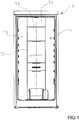
- Figure 1 shows a household refrigeration appliance 1 with a sole refrigeration cavity 12 formed by an inner coating 10 delimiting the inner space of the cavity 12 with five structural walls 14.
- the appliance is shown from a front view without showing the door of the appliance 1.
- a part of the structural wall 14 of the bottom is covered by a cover 20 with a perimeter 25 and windows 23.
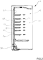
- FIG. 2 shows a cross section through the vertical of the household refrigeration appliance from figure 1 .
- a cavity 12 is shown formed by the coating 10 that is surrounded by the insulating material 13.
- a shaping is made in the manner of a channel 15 onto which a cover 20 is mounted defining an air conduit 40.
- An air guide 60 is installed in the air conduit 40. Air flows into the conduit 40 blown by a fan 50.
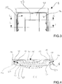
- Figure 3 shows an enlarged part of the refrigeration appliance from figure 1 indicating two section lines for figures 4 and 5 .
- Figure 4 shows section D-D indicated in figure 3 .
- a detail of the fixation of the cover 20 is shown at the height of the fixing fins 21.
- the wall 14 forms the channel 15, which is surrounded by insulating material 13 outwards.
- the edges 16 of the channel 15 have protuberances 17 onto which the shaped rims 24 of the perimeter 25 of the cover 20 connect.
- An air guide 60 is arranged inside the conduit 40, which directs air towards the windows 23 of the cover 20.
- Figure 5 shows section C-C indicated in figure 3 .
- a detail of the fixation of the cover 20 is shown at the height of the locking elements 30.
- On the perimeter 25 of the cover 20 there is a flap 22, which remains encompassed between the wall 14 of the channel 15 at the height of the edge 16 and the locking cover part 32 as it is shown more in detail in figure 6 .
- the air guide 60 is arranged inside the conduit 40.
- Figure 6 shows more in detail the fixation of the locking element 30 to the structural wall 14 on the part of the channel 15.
- the locking element 30 has a locking cavity part 31 extending through the wall 14 and a truncated-conical locking cover part 32 behind which the flap 22 of the perimeter 25 of the cover 20 is.
- a part of the air guide 60 can be seen inside the conduit 40.
Landscapes
- Engineering & Computer Science (AREA)
- Chemical & Material Sciences (AREA)
- Combustion & Propulsion (AREA)
- Physics & Mathematics (AREA)
- Mechanical Engineering (AREA)
- Thermal Sciences (AREA)
- General Engineering & Computer Science (AREA)
- Devices That Are Associated With Refrigeration Equipment (AREA)
- Cold Air Circulating Systems And Constructional Details In Refrigerators (AREA)
- Refrigerator Housings (AREA)
Abstract
Description
- The invention relates to the technical field of household refrigeration appliances comprising an inner coating forming at least a refrigerated cavity surrounded by thermally insulating material, which has a channel-shaped shaping facing the thermally insulating material with two opposed parallel edges in a structural wall of the cavity, and a cover to cover the shaping at least partially, which is fixed to the edges in a slidable manner in the direction of the edges by means of fixing fins arranged on the perimeter of the cover, and at least a flap opposed to the shaping.
- Patent application
EP 2950020 A1 describes a household refrigeration appliance provided with an air distribution system comprising a refrigerated cavity constituted by a structural wall and a cover fixed to the structural wall by means of fixing elements defining a channel between them. The structural wall has a plurality of air deflectors and at least an orifice to forcedly receive refrigerated air. The cover has a plurality of openings and a part of the refrigerated air coming from the orifice that flows to said openings of the cover through the air deflectors across the channel. The fixation of the cover to the structural wall by means of structural fixing elements makes their assembly complicated. - The object of the invention is to provide a household refrigeration appliance with a simplified and at the same time robust assembly of the cover of the distribution system of refrigerated air.
- This object is achieved by means of a household refrigeration appliance comprising an inner coating forming at least a refrigerated cavity surrounded by thermally insulating material, which has a channel-shaped shaping facing the thermally insulating material with two opposed parallel edges in a wall of the cavity, and a cover to cover the channel at least partially, which is fixed to the edges in a slidable manner in the direction of the edges by means of fixing fins arranged on the perimeter of the cover, and at least a flap opposed to the channel, wherein the appliance also comprises at least a locking element fixedly connected to the wall of the tub by means of a locking tub part and which also has a locking cover part into which the flap of the cover is connected in a slidable manner.
- The household refrigeration appliance can be a refrigeration appliance having a sole cavity or multiple refrigerated cavities. The inner coating is preferably of shaped plastics but it can be made of other conventional materials. The refrigerated cavity can have a main shape of a hexahedron with five structural walls that is surrounded by thermally insulating material such as conventional PU foam in this type of appliances and can be closed by an also thermally insulated swing door defining the sixth structural wall of the cavity. Preferably but not necessarily on the wall of the bottom of the cavity, it has a channel-shaped shaping facing the insulating material and preferably in a vertical direction relative to the verticality of the household refrigeration appliance. The channel has two vertical parallel edges to which the cover is fixed by means of fixing fins it has on its perimeter. The fixing fins are anchored on the edges by pressure but allow sliding, preferably with friction, in the vertical direction of the edges. The friction exerted is enough to withstand the weight of the cover and so this does not move downwards by its own weight. On the face opposed to the channel, the cover has a flap provided to connect to the locking cover part of the locking element, which is fixed to the structural wall of the cavity inside the channel. In this manner, the flap and the locking element remain hidden by the cover, invisible observing from outside the cavity through the gap opened into the cavity with the cover installed.
- The locking element is fixed to the structural wall preferably by riveting although it can be fixed by screwing or glueing. The locking element is preferably of plastics and has a locking tub part extending through the structural wall towards the insulating material and that is deformed during the assembly so as not to be able to penetrate the wall again in the opposite direction as it happens with a rivet or a drilling bolt, remaining firmly joined to the wall. This type of known connection can be replaced by other conventional types of fixation. Besides, the locking element has a locking cover part protruding into the cavity and into which the flap of the cover is connected. The assembly method of the cover is simple. Firstly, the cover is opposed to the channel with the flap and the locking element not facing the wall in the perpendicular direction. Secondly, the cover is pushed against the edges of the channel remaining press-fitted into the channel. Thirdly, the cover is displaced in the direction of the edges of the channel towards the locking element until the flap contacts the locking element.
- To ease the mounting of the locking element, it is advantageous that the locking cover part is truncated conical. Then, it is not necessary that it has a specific mounting position relative to its symmetry axis. That is to say, mounted in any manner perpendicularly to the structural wall, the flap will be connected in the same way. It could be plate-shaped, but the truncated-conical shape also guarantees an increased contact between the flap and the locking cover part.
- This fixation type of the cover to the structural wall of the cavity is particularly robust and easy to mount. You need to exert a force higher than 50 Nm pulling the cover in the direction perpendicular to the structural wall onto which it is mounted. For a more robust fixation, two or more locking elements are provided being connected to respective flaps of the cover.
- In a more robust embodiment, the flap is arranged on the perimeter of the cover on one side of the fixing fin. Since the flap is also arranged on the perimeter of the cover, the grip force is higher when the force exerted to remove the cover is exerted from its centre. This arrangement also makes it more convenient and simplifies the configuration of the cover, which can be made as a sole film shaped in its perimeter with the fixing fin and the flap.
- It is provided that the edge of the channel has at least a protuberance towards the opposed edge and the fixing fin of the cover has at least a shaped rim that fits on the protuberance. This makes the press-fitting and the sliding of the cover on the edges more secure. It is preferable that each edge has at least a protuberance and it extends preferably in the direction of the edge. The shaped rim at the fixing fin covers a big part of and preferably the entire length of the fixing fin. For a firmer fixation, a stop is formed on the wall inside the channel limiting the displacement of the perimeter of the cover towards the conduit. Preferably, the stop and the protuberance are not arranged at the same height to prevent the fixation from being too rigid. For the sake of a better mounting, it is provided that the cover is flexible at least partially to be press-fitted into the channel and the fact that the cover is also made at least partially of a plastic material, preferably ABS, also facilitates the mounting, since the cover can be an aesthetical piece having a face seen inside the refrigerated cavity.
- Then, the channel and the cover form an air conduit for refrigerated air and the cover has at least a window for the air outflow into the refrigerated cavity. This window leads the air outflow to the required place inside the cavity. The window is usually in the front surface of the cover but it can be made as a cut-out from its perimeter. And to drive air into the conduit, a fan is provided that blows air into it.
- An air guide is provided inside the conduit to conduct air from the air inlet into the channel up to the window. This air guide can be configured in the structural wall or can be one or more independent inserts. The air guide is not made in one piece with the cover or with the structural wall, it is provided that it can be press-fitted between the wall of the shaping and the cover. It can be also fixed by glueing to one of them and by adding sealing gaskets between the guide and the wall or the cover so that air is led in a better manner.
- Other advantages derive from the following description of the figures. In the figures, an exemplary embodiment of the invention is represented. The figures, the description and the patent claims contain numerous features in combination. The expert shall also advantageously consider said features separately and join them in other appropriate combinations.
- These show:
- figure 1
- shows a front view of the household refrigeration appliance,
- figure 2
- shows a section of the appliance from
figure 1 , - figure 3
- shows a detail of the top of the household refrigeration appliance from
figure 1 , - figure 4
- shows section D-D indicated in
figure 3 , - figure 5
- shows section C-C indicated in
figure 3 , and - figure 6
- shows an enlarged detail from
figure 5 . -
Figure 1 shows ahousehold refrigeration appliance 1 with asole refrigeration cavity 12 formed by aninner coating 10 delimiting the inner space of thecavity 12 with fivestructural walls 14. The appliance is shown from a front view without showing the door of theappliance 1. A part of thestructural wall 14 of the bottom is covered by acover 20 with aperimeter 25 andwindows 23. -
Figure 2 shows a cross section through the vertical of the household refrigeration appliance fromfigure 1 . In this, acavity 12 is shown formed by thecoating 10 that is surrounded by the insulatingmaterial 13. On thestructural wall 14 of the bottom of thecavity 12, a shaping is made in the manner of achannel 15 onto which acover 20 is mounted defining anair conduit 40. Anair guide 60 is installed in theair conduit 40. Air flows into theconduit 40 blown by afan 50. -
Figure 3 shows an enlarged part of the refrigeration appliance fromfigure 1 indicating two section lines forfigures 4 and5 . -
Figure 4 shows section D-D indicated infigure 3 . A detail of the fixation of thecover 20 is shown at the height of the fixingfins 21. Thewall 14 forms thechannel 15, which is surrounded by insulatingmaterial 13 outwards. Theedges 16 of thechannel 15 haveprotuberances 17 onto which the shapedrims 24 of theperimeter 25 of thecover 20 connect. In thechannel 15 there is an additional shaping in the manner of astop 19 limiting the movement of theperimeter 25 of thecover 20 into theconduit 40, thereby making the fixation firmer. Anair guide 60 is arranged inside theconduit 40, which directs air towards thewindows 23 of thecover 20. -
Figure 5 shows section C-C indicated infigure 3 . A detail of the fixation of thecover 20 is shown at the height of the lockingelements 30. On theperimeter 25 of thecover 20 there is aflap 22, which remains encompassed between thewall 14 of thechannel 15 at the height of theedge 16 and the lockingcover part 32 as it is shown more in detail infigure 6 . Theair guide 60 is arranged inside theconduit 40. -
Figure 6 shows more in detail the fixation of the lockingelement 30 to thestructural wall 14 on the part of thechannel 15. The lockingelement 30 has alocking cavity part 31 extending through thewall 14 and a truncated-conical locking coverpart 32 behind which theflap 22 of theperimeter 25 of thecover 20 is. A part of theair guide 60 can be seen inside theconduit 40. - 1
- household refrigeration appliance
- 10
- inner coating
- 12
- refrigerated cavity
- 13
- thermally insulating material
- 14
- structural wall
- 15
- channel
- 16
- edges
- 17
- protuberance
- 20
- cover
- 21
- fixing fins
- 22
- flap
- 23
- air outlet, window
- 24
- shaped rim
- 25
- perimeter
- 30
- locking element
- 31
- locking cavity part
- 32
- locking cover part
- 40
- air conduit
- 50
- fan
- 60
- air guide
Claims (11)
- A household refrigeration appliance (1) comprising
an inner coating (10) forming at least a refrigerated cavity (12) surrounded by thermally insulating material (13), which has a channel-shaped shaping (15) facing the thermally insulating material (13) with two opposed parallel edges (16) in a structural wall (14) of the cavity (12), and
a cover (20) to cover the channel (15) at least partially, which is fixed to the edges (16) in a slidable manner in the direction of the edges (16) by means of fixing fins (21) arranged on the perimeter (25) of the cover (20), and
at least a flap (22) opposed to the channel (15),
characterized in that
it also comprises at least a locking element (30) fixedly connected to the structural wall (14) of the cavity (12) by means of a locking cavity part (31) and which also has a locking cover part (32) into which the flap (22) of the cover (20) is connected in a slidable manner. - The household refrigeration appliance according to claim 1, characterized in that it has at least two locking elements (30) connected to respective flaps (22) of the cover (20).
- The household refrigeration appliance according to one of the preceding claims, characterized in that the flap (22) is arranged on the perimeter (25) of the cover (20) on one side of the fixing fin (21).
- The household refrigeration appliance according to one of the preceding claims, characterized in that at least an edge (16) of the channel (15) has at least a protuberance (17) towards the opposed edge (16) and the fixing fin (21) of the cover (20) has a shaped rim (24) that fits on the protuberance (17).
- The household refrigeration appliance according to one of the preceding claims, characterized in that the cover (20) is flexible at least partially to be press-fitted into the channel (15).
- The household refrigeration appliance according to one of the preceding claims, characterized in that the cover (20) is made of plastics, preferably ABS.
- The household refrigeration appliance according to one of the preceding claims, characterized in that the locking cover part (32) is truncated conical.
- The household refrigeration appliance according to one of the preceding claims, characterized in that the channel (15) and the cover (20) form an air conduit (40) for air and the cover (20) has at least a window (23) for the air outflow into the refrigerated cavity (12).
- The household refrigeration appliance according to claim 8, characterized in that it comprises a fan (50) blowing air into the conduit (40) formed by the channel (15) and the cover (20).
- The household refrigeration appliance according to one of claims 8 or 9, characterized in that it comprises an air guide (60) inside the conduit (40).
- The household refrigeration appliance according to claim 10, characterized in that the air guide (60) is press-fitted between the channel (15) and the cover (20).
Applications Claiming Priority (1)
| Application Number | Priority Date | Filing Date | Title |
|---|---|---|---|
| ES201800187A ES2740818B2 (en) | 2018-08-06 | 2018-08-06 | Domestic refrigerator appliance with an internal channel for the distribution of cooled air |
Publications (1)
| Publication Number | Publication Date |
|---|---|
| EP3608612A1 true EP3608612A1 (en) | 2020-02-12 |
Family
ID=67514344
Family Applications (1)
| Application Number | Title | Priority Date | Filing Date |
|---|---|---|---|
| EP19188847.8A Withdrawn EP3608612A1 (en) | 2018-08-06 | 2019-07-29 | Household refrigeration appliance |
Country Status (2)
| Country | Link |
|---|---|
| EP (1) | EP3608612A1 (en) |
| ES (1) | ES2740818B2 (en) |
Cited By (1)
| Publication number | Priority date | Publication date | Assignee | Title |
|---|---|---|---|---|
| US20220275991A1 (en) * | 2020-12-14 | 2022-09-01 | Whirlpool Corporation | Refrigerator system |
Citations (6)
| Publication number | Priority date | Publication date | Assignee | Title |
|---|---|---|---|---|
| FR1298250A (en) * | 1961-08-23 | 1962-07-06 | Bosch Gmbh Robert | Spacer assembly device, in particular for suspending a refrigeration machine evaporator |
| KR20090131216A (en) * | 2008-06-17 | 2009-12-28 | 엘지전자 주식회사 | Shelf fixture of the refrigerator |
| DE102011006256A1 (en) * | 2011-03-28 | 2012-10-04 | BSH Bosch und Siemens Hausgeräte GmbH | Refrigerating appliance with molded air duct |
| JP2013164259A (en) * | 2013-05-28 | 2013-08-22 | Panasonic Corp | Refrigerator |
| EP2950020A1 (en) | 2014-05-26 | 2015-12-02 | Whirlpool S.A. | Refrigerator provided with air distribution system |
| DE102015203145A1 (en) * | 2015-02-23 | 2016-08-25 | BSH Hausgeräte GmbH | COOLING UNIT |
Family Cites Families (6)
| Publication number | Priority date | Publication date | Assignee | Title |
|---|---|---|---|---|
| DE202005014378U1 (en) * | 2005-09-12 | 2006-01-12 | BSH Bosch und Siemens Hausgeräte GmbH | No-frost refrigerating appliance |
| DE102007005953A1 (en) * | 2007-02-06 | 2008-08-07 | BSH Bosch und Siemens Hausgeräte GmbH | Refrigeration unit with circulating air cooling |
| DE102011077824A1 (en) * | 2011-06-20 | 2012-12-20 | BSH Bosch und Siemens Hausgeräte GmbH | Refrigerating appliance with air duct |
| KR101700501B1 (en) * | 2015-03-25 | 2017-01-26 | 엘지전자 주식회사 | A refrigerator and a method controlling the same |
| DE102016224608A1 (en) * | 2016-12-09 | 2018-06-14 | BSH Hausgeräte GmbH | Domestic refrigerating appliance with specific covering system in a food receiving space |
| DE102016224610A1 (en) * | 2016-12-09 | 2018-06-14 | BSH Hausgeräte GmbH | Domestic refrigerator with specific attachment of a cover plate to a receiving space for food and method for mounting such a cover plate |
-
2018
- 2018-08-06 ES ES201800187A patent/ES2740818B2/en active Active
-
2019
- 2019-07-29 EP EP19188847.8A patent/EP3608612A1/en not_active Withdrawn
Patent Citations (6)
| Publication number | Priority date | Publication date | Assignee | Title |
|---|---|---|---|---|
| FR1298250A (en) * | 1961-08-23 | 1962-07-06 | Bosch Gmbh Robert | Spacer assembly device, in particular for suspending a refrigeration machine evaporator |
| KR20090131216A (en) * | 2008-06-17 | 2009-12-28 | 엘지전자 주식회사 | Shelf fixture of the refrigerator |
| DE102011006256A1 (en) * | 2011-03-28 | 2012-10-04 | BSH Bosch und Siemens Hausgeräte GmbH | Refrigerating appliance with molded air duct |
| JP2013164259A (en) * | 2013-05-28 | 2013-08-22 | Panasonic Corp | Refrigerator |
| EP2950020A1 (en) | 2014-05-26 | 2015-12-02 | Whirlpool S.A. | Refrigerator provided with air distribution system |
| DE102015203145A1 (en) * | 2015-02-23 | 2016-08-25 | BSH Hausgeräte GmbH | COOLING UNIT |
Cited By (2)
| Publication number | Priority date | Publication date | Assignee | Title |
|---|---|---|---|---|
| US20220275991A1 (en) * | 2020-12-14 | 2022-09-01 | Whirlpool Corporation | Refrigerator system |
| US12181200B2 (en) * | 2020-12-14 | 2024-12-31 | Whirlpool Corporation | Refrigerator system |
Also Published As
| Publication number | Publication date |
|---|---|
| ES2740818A1 (en) | 2020-02-06 |
| ES2740818B2 (en) | 2021-01-20 |
Similar Documents
| Publication | Publication Date | Title |
|---|---|---|
| CN101680703B (en) | Domestic appliance | |
| RU2467265C2 (en) | Household appliance | |
| US12163727B2 (en) | Domestic refrigeration device | |
| CN101175958A (en) | door for household appliances | |
| US20180149408A1 (en) | Home Appliance Device and Method for Assembling a Home Appliance Device | |
| US10473262B2 (en) | Household refrigeration appliance with non-destructively releasable roller assembly in the base of a housing and method for producing the household refrigeration appliance | |
| EP2982917B1 (en) | Refrigeration appliance having embedded handle | |
| EP3438580A1 (en) | Door bin with dual material and locking system | |
| KR20150091006A (en) | Vane and air vent | |
| US10228185B2 (en) | Assembly for a domestic refrigeration appliance with a wire basket and domestic refrigeration appliance with such an assembly | |
| US20180149407A1 (en) | Home Appliance Device | |
| KR20130057563A (en) | Air conditioner for vehicles | |
| KR101769180B1 (en) | Structure reinforcement assembly for fittings | |
| CN109387017A (en) | Refrigerating appliance with evaporating pan | |
| CN103608631B (en) | Refrigerating appliances with air channels | |
| ES2740818B2 (en) | Domestic refrigerator appliance with an internal channel for the distribution of cooled air | |
| EP3071908B1 (en) | Refrigerator | |
| US11326831B2 (en) | Household appliance apparatus with a flow separating unit and household appliance | |
| US20080164797A1 (en) | Refrigerator and shelf for the same | |
| US10253554B2 (en) | Home appliance device comprising a door and home appliance device | |
| ITMI20001057A1 (en) | STATIC REFRIGERATOR WITH AIR CHANNEL EVAPORATOR | |
| EP2935998B1 (en) | Method for attaching an oven seal and oven seal | |
| US20180156519A1 (en) | Home Appliance Device | |
| CN103459951B (en) | Refrigeration appliances with axial fans | |
| EP2035752B1 (en) | An oven |
Legal Events
| Date | Code | Title | Description |
|---|---|---|---|
| PUAI | Public reference made under article 153(3) epc to a published international application that has entered the european phase |
Free format text: ORIGINAL CODE: 0009012 |
|
| STAA | Information on the status of an ep patent application or granted ep patent |
Free format text: STATUS: THE APPLICATION HAS BEEN PUBLISHED |
|
| AK | Designated contracting states |
Kind code of ref document: A1 Designated state(s): AL AT BE BG CH CY CZ DE DK EE ES FI FR GB GR HR HU IE IS IT LI LT LU LV MC MK MT NL NO PL PT RO RS SE SI SK SM TR |
|
| AX | Request for extension of the european patent |
Extension state: BA ME |
|
| STAA | Information on the status of an ep patent application or granted ep patent |
Free format text: STATUS: REQUEST FOR EXAMINATION WAS MADE |
|
| 17P | Request for examination filed |
Effective date: 20200812 |
|
| RBV | Designated contracting states (corrected) |
Designated state(s): AL AT BE BG CH CY CZ DE DK EE ES FI FR GB GR HR HU IE IS IT LI LT LU LV MC MK MT NL NO PL PT RO RS SE SI SK SM TR |
|
| GRAP | Despatch of communication of intention to grant a patent |
Free format text: ORIGINAL CODE: EPIDOSNIGR1 |
|
| STAA | Information on the status of an ep patent application or granted ep patent |
Free format text: STATUS: GRANT OF PATENT IS INTENDED |
|
| INTG | Intention to grant announced |
Effective date: 20211210 |
|
| STAA | Information on the status of an ep patent application or granted ep patent |
Free format text: STATUS: THE APPLICATION IS DEEMED TO BE WITHDRAWN |
|
| 18D | Application deemed to be withdrawn |
Effective date: 20220421 |