EP3608592B1 - Heizgerät, das lufteinspritzleitungen umfasst - Google Patents
Heizgerät, das lufteinspritzleitungen umfasst Download PDFInfo
- Publication number
- EP3608592B1 EP3608592B1 EP19189517.6A EP19189517A EP3608592B1 EP 3608592 B1 EP3608592 B1 EP 3608592B1 EP 19189517 A EP19189517 A EP 19189517A EP 3608592 B1 EP3608592 B1 EP 3608592B1
- Authority
- EP
- European Patent Office
- Prior art keywords
- combustion chamber
- air
- air injection
- heating apparatus
- combustion
- Prior art date
- Legal status (The legal status is an assumption and is not a legal conclusion. Google has not performed a legal analysis and makes no representation as to the accuracy of the status listed.)
- Active
Links
Images


Classifications
-
- F—MECHANICAL ENGINEERING; LIGHTING; HEATING; WEAPONS; BLASTING
- F24—HEATING; RANGES; VENTILATING
- F24B—DOMESTIC STOVES OR RANGES FOR SOLID FUELS; IMPLEMENTS FOR USE IN CONNECTION WITH STOVES OR RANGES
- F24B5/00—Combustion-air or flue-gas circulation in or around stoves or ranges
- F24B5/02—Combustion-air or flue-gas circulation in or around stoves or ranges in or around stoves
- F24B5/021—Combustion-air or flue-gas circulation in or around stoves or ranges in or around stoves combustion-air circulation
- F24B5/026—Supply of primary and secondary air for combustion
-
- F—MECHANICAL ENGINEERING; LIGHTING; HEATING; WEAPONS; BLASTING
- F23—COMBUSTION APPARATUS; COMBUSTION PROCESSES
- F23L—SUPPLYING AIR OR NON-COMBUSTIBLE LIQUIDS OR GASES TO COMBUSTION APPARATUS IN GENERAL ; VALVES OR DAMPERS SPECIALLY ADAPTED FOR CONTROLLING AIR SUPPLY OR DRAUGHT IN COMBUSTION APPARATUS; INDUCING DRAUGHT IN COMBUSTION APPARATUS; TOPS FOR CHIMNEYS OR VENTILATING SHAFTS; TERMINALS FOR FLUES
- F23L9/00—Passages or apertures for delivering secondary air for completing combustion of fuel
- F23L9/02—Passages or apertures for delivering secondary air for completing combustion of fuel by discharging the air above the fire
-
- F—MECHANICAL ENGINEERING; LIGHTING; HEATING; WEAPONS; BLASTING
- F23—COMBUSTION APPARATUS; COMBUSTION PROCESSES
- F23L—SUPPLYING AIR OR NON-COMBUSTIBLE LIQUIDS OR GASES TO COMBUSTION APPARATUS IN GENERAL ; VALVES OR DAMPERS SPECIALLY ADAPTED FOR CONTROLLING AIR SUPPLY OR DRAUGHT IN COMBUSTION APPARATUS; INDUCING DRAUGHT IN COMBUSTION APPARATUS; TOPS FOR CHIMNEYS OR VENTILATING SHAFTS; TERMINALS FOR FLUES
- F23L9/00—Passages or apertures for delivering secondary air for completing combustion of fuel
- F23L9/06—Passages or apertures for delivering secondary air for completing combustion of fuel by discharging the air into the fire bed
-
- F—MECHANICAL ENGINEERING; LIGHTING; HEATING; WEAPONS; BLASTING
- F23—COMBUSTION APPARATUS; COMBUSTION PROCESSES
- F23M—CASINGS, LININGS, WALLS OR DOORS SPECIALLY ADAPTED FOR COMBUSTION CHAMBERS, e.g. FIREBRIDGES; DEVICES FOR DEFLECTING AIR, FLAMES OR COMBUSTION PRODUCTS IN COMBUSTION CHAMBERS; SAFETY ARRANGEMENTS SPECIALLY ADAPTED FOR COMBUSTION APPARATUS; DETAILS OF COMBUSTION CHAMBERS, NOT OTHERWISE PROVIDED FOR
- F23M5/00—Casings; Linings; Walls
- F23M5/02—Casings; Linings; Walls characterised by the shape of the bricks or blocks used
-
- F—MECHANICAL ENGINEERING; LIGHTING; HEATING; WEAPONS; BLASTING
- F24—HEATING; RANGES; VENTILATING
- F24B—DOMESTIC STOVES OR RANGES FOR SOLID FUELS; IMPLEMENTS FOR USE IN CONNECTION WITH STOVES OR RANGES
- F24B1/00—Stoves or ranges
- F24B1/18—Stoves with open fires, e.g. fireplaces
- F24B1/185—Stoves with open fires, e.g. fireplaces with air-handling means, heat exchange means, or additional provisions for convection heating ; Controlling combustion
- F24B1/189—Stoves with open fires, e.g. fireplaces with air-handling means, heat exchange means, or additional provisions for convection heating ; Controlling combustion characterised by air-handling means, i.e. of combustion-air, heated-air, or flue-gases, e.g. draught control dampers
- F24B1/19—Supplying combustion-air
- F24B1/1902—Supplying combustion-air in combination with provisions for heating air only
Definitions
- the present application relates to a heating apparatus comprising at least one air injection ramp.
- the document EP-867662 describes a double-hearth fireplace which has a combustion chamber comprising an upper opening closed by two removable plates. According to this embodiment, the first hearth is positioned on the removable plates and the second hearth is positioned in the combustion chamber, below the removable plates.
- the air required for the combustion of the fuel enters the combustion chamber through the upper opening, which is not completely obstructed by the two removable plates.
- the removable plates and the perimeter of the upper opening are configured so that there is a clearance between the two removable plates and between the removable plates and the perimeter of the opening.
- a first casing is provided around at least a portion of the side walls of the combustion chamber.
- the space between the side walls and the first casing is intended for the circulation of combustion products from the combustion chamber to an exhaust duct.
- the right and left side walls of the combustion chamber are spaced from the front side wall so as to create two lateral exhaust openings.
- the combustion products are evacuated from the combustion chamber via these lateral exhaust openings, then they travel to the rear of the right and left side walls of the combustion chamber to reach the exhaust duct positioned at the rear of the rear side wall of the combustion chamber.
- a second envelope is provided around the first envelope, a space between the first and second envelopes being provided for the circulation of air from the room to be heated.
- the rear wall of the combustion chamber includes a direct discharge opening that directly connects the combustion chamber and the discharge duct. Depending on the spacing between the removable plates, a re-ignition of the fumes is obtained at the direct discharge opening, which reduces the amount of unburned material and increases the thermal efficiency of the combustion chamber.
- the document FR-2947037 proposes a solution to further reduce the quantity of unburned material and increase thermal efficiency.
- two air introduction ducts are positioned at each of the side exhaust openings.
- Each duct is positioned vertically and includes a plurality of orifices.
- These air introduction ducts positioned on the combustion product evacuation path, make it possible to relight a greater quantity of combustion products and therefore reduce the quantity of unburned material and increase thermal efficiency.
- the direct exhaust port or air introduction ducts are used to optimize post-combustion.
- the stove comprises an enclosure with a combustion chamber at the bottom, topped with a flue for evacuating the burnt gases.
- the enclosure has a perforated lower wall for supplying air for the main combustion and a ramp for injecting air between the combustion chamber and the evacuation flue to ensure post-combustion.
- the stove comprises an enclosure, with a combustion chamber in the lower part in which a movable flap is positioned, above the combustion chamber, allowing two paths for the combustion gases to be defined.
- the air intended for the main combustion is supplied from the bottom of the combustion chamber.
- the stove also includes an air injection ramp to initiate post-combustion when the flap is in the open position.
- the air supply for the main combustion is achieved via openings provided at the level of the lower wall. This configuration is not optimal because the openings can be partially or completely blocked by the ash generated by the combustion.
- US4249509 A discloses a heating apparatus comprising a primary air injection ramp in the lower part of the combustion chamber, and a second chamber for post-combustion.
- the present invention aims to remedy all or part of the drawbacks of the prior art by proposing a solution which improves combustion.
- the heating appliance comprises at least one air circuit for supplying the combustion chamber with air, comprising at least two air injection rails.
- Each injection rail comprises one or more sections comprising the injection orifices, opening into the combustion chamber, separated from each other by a distance less than or equal to 5 cm, and extending over at least 30% of the perimeter of the combustion chamber.
- the presence of at least two air injection ramps allows better control of the air supply required for combustion, which optimizes combustion and consequently reduces the quantity of unburned matter in the combustion products and increases the thermal efficiency of combustion.
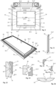
- a heating appliance is shown at 10 which has a combustion chamber 12.
- a heating appliance is intended to be positioned in a room, more particularly in a fireplace.
- the combustion chamber 12 has a bottom 12.1, side walls 12.2 to 12.5 and an upper opening 14 closed by at least one removable plate 16 (visible in dotted lines on the Figure 3 and in solid line on the figure 9 ).
- the heating appliance 10 comprises two hearths, a first hearth 18.1 in the combustion chamber 12, under the removable plate(s) 16, and a second hearth 18.2, outside the combustion chamber 12, above the removable plate(s) 16.
- the combustion chamber 12 has a parallelepiped shape and has a front side wall 12.2, a rear side wall 12.3, a right side wall 12.4 and a left side wall 12.5.
- the heating appliance 10 comprises an evacuation conduit 20 for the combustion products generated during combustion of a fuel, in particular wood, in the combustion chamber 12.
- the heating apparatus 10 comprises at least one combustion product treatment system and/or a heat exchanger.
- the heating appliance 10 comprises a first casing 22 around the combustion chamber 12 and spaced apart from at least a portion of the side walls 12.2 to 12.5 of the combustion chamber 12 so as to form a first circuit 24 for the circulation of the combustion products from the combustion chamber 12 to the exhaust duct 20.
- the first circuit 24 has a U-shape, seen from above, and has a central portion 24.1, positioned between the rear side wall 12.3 and the first casing 22, a right portion 24.2, positioned between the right side wall 12.4 and the first casing 22, and a left portion 24.3 positioned between the left side wall 12.5 and the first casing 22.
- the right and left side walls 12.4, 12.5 of the combustion chamber 12 are spaced from the front side wall 12.2 so as to create two lateral exhaust openings 26, 26' which communicate with the right and left portions 24.2, 24.3 of the first circuit 24.
- the central portion 24.1 of the first circuit 24 communicates with the exhaust duct 20 which is positioned above the central portion 24.1 of the first circuit 24, in a centered manner relative to the right and left portions 24.2, 24.3.
- the combustion products are evacuated from the combustion chamber 12 via these lateral exhaust openings 26, 26'. They then travel behind the right and left side walls 12.4, 12.5, then behind the rear side wall 12.3 of the combustion chamber 12 to reach the exhaust duct 20 positioned behind the rear side wall 12.3 of the combustion chamber 12.
- the heating apparatus 12 comprises a second casing 28 positioned around the first casing 22 and spaced from the first casing 22 so as to form between the first and second casings 22, 28 a second circuit 30 for the circulation of the air of the room to be heated.
- the first and second circuits 24, 30 form a heat exchanger, the first casing 22 ensuring a heat transfer between the combustion products and the air in the room to be heated.
- the apparatus comprises a first system for treating the combustion products in the form of an orifice 31 passing through the rear side wall 12.3, directly connecting the combustion chamber 12 and the central portion 24.1 of the first circuit 24 itself directly connected to the evacuation duct 20.
- This first system for treating the combustion products, in the form of an orifice can be omitted taking into account the improvement in combustion provided by the invention.
- the front, rear, right and left side walls 12.2 to 12.5 are formed from bricks made of refractory material.
- the first and second envelopes 22, 28, the first combustion product treatment system are not further detailed because they can be identical to those described in the documents EP-867622 And FR-2947037 of the prior art.
- the heating appliance 10 comprises a system for supplying air to the combustion chamber.
- This supply system comprises at least one air injection ramp 32 which has a plurality of orifices 34 opening into the combustion chamber 12, to supply it with air for the main combustion in particular.
- Each air injection ramp 32 comprises one or more sections comprising injection orifices 34 separated from each other by a distance less than or equal to 5 cm, the sections of the same air injection ramp 32 extending over at least 30% of the perimeter of the combustion chamber 12.
- the air injection ramp 32 comprises two sections T1 and T2 which extend over two side walls representing at least 30% of the perimeter of the chamber 12.
- the air injection ramp 32 comprises a first section T3 which extends over the entire length of the rear side wall 12.3, a second section T4 which extends over a portion of the length of the right side wall 12.4 and a third section T5 which extends over a portion of the length of the left side wall 12.5.
- the length of a side wall corresponds to the dimension of the side wall taken in a substantially horizontal plane.
- the air injection ramp 32 comprises, on each of the side walls 12.2 to 12.5, two sections referenced T6 to T13.
- At least one section of at least one air injection rail 32 is integrated into the rear side wall 12.3, the right side wall 12.4 and/or the left side wall 12.5.
- no element of the air injection rail 32 projects into the combustion chamber 12, which increases the robustness of the device.
- the rail air injection 32 is flush with the inner face of the rear side wall 12.3, the right side wall 12.4 and/or the left side wall 12.5.
- At least one section of the air injection ramp 32 is positioned between the combustion chamber 12 and the first circuit 24 for the combustion products. This configuration makes it possible to preheat the air injected into the combustion chamber 12.
- the section(s) of an air injection ramp 32 extend(s) over at least 80% of the perimeter of the combustion chamber 12.
- the injection ports 34 of an air injection rail 32 may all have the same passage section or have different passage sections, as illustrated in the Figure 6D .
- the injection orifices 34 may have passage sections in the form of a slot, circular, oblong, triangular or other. As illustrated in the Figure 6D , the injection orifices 34 of an air injection ramp 32 may have a regular or irregular pitch.
- the air injection ramp 32 extends around the entire circumference of the combustion chamber 12 and comprises injection orifices 34 distributed around the entire circumference of the combustion chamber 12, with a regular pitch of the order of 15 to 40 mm, a circular passage section of the order of 0.6 to 10 mm.
- the injection orifices 34 may be distributed with a non-regular pitch.
- the injection orifices 34 have a passage section, a positioning and/or a pitch determined so as to obtain substantially homogeneous injected air flows around the entire perimeter of the combustion chamber 12.
- each air injection ramp 32 is positioned in a substantially horizontal plane.
- the combustion chamber 12 comprises at least one air injection ramp 32 positioned at a height less than or equal to 0.75 times the height of the combustion chamber 12, from the bottom 12.1 of the combustion chamber 12.
- the height corresponds to the dimension of the side walls taken in a substantially vertical plane.
- the air injection ramp 32 is located at a distance from the bottom less than or equal to 23 cm.
- the air injection ramp 32 is positioned approximately at mid-height or slightly above mid-height.
- the combustion chamber 12 comprises two air injection ramps 32, 32', a first air injection ramp 32, positioned between 0.4 and 0.75 times the height of the combustion chamber 12 from the bottom 12.1 of the combustion chamber 12, and a second air injection ramp 32' attached to the bottom 12.1 of the combustion chamber.
- the orifices 34 of the second air injection ramp 32' are spaced from the bottom 12.1 of the combustion chamber 12 so as to prevent them from being blocked by ash.
- the presence of at least two air injection ramps 32, 32' allows better control of the air supply necessary for combustion, which makes it possible to optimize combustion and consequently to reduce the quantity of unburned matter in the combustion products and to increase the thermal efficiency of the combustion.
- each air injection ramp 32, 32' comprises at least one hollow tube with a square or rectangular section which has a thickness substantially equal to that of the side walls 12.2 to 12.5.
- each injection ramp 32, 32' is integrated into the side walls 12.2, 12.5 of the combustion chamber 12.
- each side wall 12.2 to 12.5 comprises, in the lower part, a first tube of square or rectangular hollow section which forms the second air injection ramp 32'; a first row of bricks 36, of at least one brick made of refractory material, positioned above the second air injection ramp 32'; a second tube of square or rectangular hollow section which forms the first air injection ramp 32, positioned above the first row of bricks 36; and a second row of bricks 38, of at least one brick made of refractory material, positioned above the first injection ramp 32.
- the lateral discharge openings 26, 26' are delimited at the top and bottom by the first and second air injection ramps 32, 32'.
- the first air injection ramp 32 comprises a lower face of which a zone 40, 40' forms the upper edge of the discharge opening 26, 26'
- the second air injection ramp 32' comprising an upper face of which a zone 42, 42' forms the lower edge of the discharge opening 26, 26'.
- the heating appliance 10 comprises, at at least one of the lateral discharge openings 26, 26', a second combustion product treatment system.
- each second combustion product treatment system comprises at least one air injection orifice 44, 46, at at least one of the first or second air injection ramps 32, 32', oriented towards the lateral discharge opening 26, 26'.
- the zone 40, 40' of the first air injection ramp 32 comprises an orifice 44 opening at the lateral discharge opening 26, 26' and the zone 42, 42' of the second air injection ramp 32' comprises an orifice 46 opening at the lateral discharge opening 26, 26'.
- the first circuit 24 of the combustion products comprises at least one lateral discharge opening 26, 26' which passes through one of the side walls 12.2 to 12.5 of the combustion chamber and which is adjacent to at least one air injection ramp 32, 32'.
- At least one of the air injection ramps 32 adjacent to the lateral discharge opening 26, 26' comprises at least one orifice 44, 46 opening into the lateral discharge opening 26, 26' for injecting air in order to ensure treatment of the combustion products.
- the same air injection ramp 32 injects the air intended for the main combustion and for the post-combustion.
- the heating apparatus comprises at least one air circuit 56 (or 56') for supplying the combustion chamber 12 with air which comprises, in addition to the air injection ramp 32 (or 32'), a third transverse tube 58 (or 58'), parallel to the first and second transverse tubes 52, 54 (or 52', 54'), connecting the longitudinal tubes 48, 50 (or 48', 50') at their second ends, configured to be positioned between the first and second casings 22, 28 and supplied with air, said circuit 56 (or 56') comprising at least one air supply orifice.
- each circuit 56 comprises first and second air supply ports 60, 62 (or 60', 62') provided at the ends of the third transverse tube 58 (or 58') and/or a third air supply port 64 (or 64') provided equidistant from the ends of the third transverse tube 58 (or 58').
- Each air circuit 56, 56' is configured to obtain air flows injected through the injection orifices 34 that are substantially homogeneous around the entire perimeter of the combustion chamber 12.
- each air circuit 56, 56' comprises at least one pipe 66.1 to 66.3 configured to connect each supply port 60, 62, 64 to an air supply A which may be unique.
- Each duct 66.1 to 66.3 may comprise an air flow regulation system 68.1 to 68.3, for example in the form of a register or a diaphragm.
- each air circuit 56, 56' comprises at least one air flow regulation system 68.1 to 68.3 in the form of a diaphragm. The latter makes it possible to adjust the air flow more precisely and centered relative to the pipe 66.1 to 66.3.
- the air flow regulation systems 68.1 to 68.3 are arranged upstream of the supply orifices 60, 62, 64. Alternatively, they could be arranged downstream.
- each air flow regulation system 68.1 to 68.3 could be associated with an air flow straightening system 70 so that the channeled air flow 72 is as swirl-free as possible.
- each straightening system 70 is positioned downstream of the regulation system and is in the form of a plate 74 closing the duct 66.1 to 66.3 and having a multitude of through holes 76.
- the invention is not limited to this positioning for the air flow straightening system 70.
- an air flow straightening system 70 could be positioned in each of the ramps so that the channeled air flow 72 is as swirl-free as possible. The presence of this straightening system 70 makes it possible to manage the channeled air flow 72 more precisely.
- the heating apparatus 10 comprises an upper plate 78 which has a rim 80 delimiting the upper opening 14 of the combustion chamber 12.
- the rim 80 of the upper plate 78 and each removable plate 16 are configured to limit air leaks between the inside and the outside of the combustion chamber 12 when each removable plate 16 is in the closed position.
- the edge 80 of the upper plate 78 and each front and rear removable plate 16, 16' are configured to limit the passage of air between the two front and rear removable plates 16, 16' and between each of the front or rear removable plates 16, 16' and the edge 80 of the plate upper 78 when both front and rear removable plates 16, 16' are in the closed position, as shown in the Figure 9 .
- the edge 80 of the upper plate 78 has a front side 80.1, a right side 80.2, a left side 80.3 and a rear side 80.4.
- the front removable plate 16 comprises a front edge 16.1, a right edge 16.2, a left edge 16.3 configured to cooperate respectively with the front side 80.1, the right side 80.2, the left side 80.3 of the rim 80 of the upper plate 78 as well as a rear edge 16.4 configured to cooperate with the front edge 16.1' of the rear removable plate 16'.
- the latter also comprises a right edge 16.2', a left edge 16.3' and a rear edge 16.4' configured to cooperate respectively with the right side 80.2, the left side 80.3 and the rear side 80.4 of the rim 80 of the upper plate 78.
- sealing gaskets are provided between the rear edge 16.4 of the front removable plate 16 and the front edge 16.1' of the rear removable plate 16', and between the other edges of the front and rear removable plates 16, 16' and the four sides of the rim 80 of the upper plate 78.
- the front edges 16.1, right 16.2 and left 16.3 of the front removable plate 16 have complementary shapes with the front sides 80.1, right 80.2, left 80.3 of the rim 80 of the upper plate 78.
- the right 16.2', left 16.3', rear 16.4' edges of the rear removable plate 16' have shapes complementary to the right 80.2, left 80.3 and rear 80.4 sides of the rim 80 of the upper plate 78, as illustrated in the figure 13 .
- two elements have complementary shapes when there remains a small clearance between them when they cooperate.
- the front edges 16.1, right 16.2 and left 16.3 of the front removable plate 16 comprise projecting ribs 82 configured to cooperate with recessed grooves 84 provided at the front 80.1, right 80.2, left 80.3 sides of the rim 80 of the upper plate 78.
- the right 16.2', left 16.3', rear 16.4' edges of the rear removable plate 16' comprise projecting ribs 86 configured to cooperate with recessed grooves 88 provided at the right 80.2, left 80.3 and rear 80.4 sides of the rim 80 of the upper plate 78.
- the rear edge 16.4 of the front removable plate 16 comprises a projecting rib 90 configured to cooperate with a recessed groove 92 provided at the front edge 16.1' of the rear removable plate 16'.
- the front edge 16.1 of the front removable plate 16 and the front side 80.1 of the rim 80 of the upper plate 78 each have an inclined face 96, 96' to facilitate the passage of the front removable plate 16 above the rim 80 of the upper plate 78 when said front removable plate 16 is moved away from the rear removable plate 16'.
- the right and left sides 80.2, 80.3 of the rim 80 of the upper plate 78 each comprise a recessed notch 98.
- the front plate 16 comprises, at its lower face, a right transverse boss 100 and a left transverse boss 100' configured to cooperate with the recessed notches 98 provided at the right and left sides 80.2, 80.3 of the rim 80 of the upper plate 78 when the front removable plate 16 is in the closed position.
- the transverse bosses 100, 100' slide along the right and left sides 80.2, 80.3 of the rim 80 of the upper plate 78 so as to cause a slight lifting of the front removable plate 16.
- removable plates 16, 16' and/or the upper plate 78 can be molded and machined subsequently to improve the sealing, the sliding of the removable plates 16, 16' and reduce the noise during their sliding.
Landscapes
- Engineering & Computer Science (AREA)
- Chemical & Material Sciences (AREA)
- Combustion & Propulsion (AREA)
- Mechanical Engineering (AREA)
- General Engineering & Computer Science (AREA)
- Air Supply (AREA)
Claims (10)
- Heizgerät mit einer Brennkammer (12), die einen Boden (12.1), Seitenwände (12.2 bis 12.5) und eine obere Öffnung (14) aufweist, die durch wenigstens eine abnehmbare Platte (16) verschlossen ist, wobei das Heizgerät auch eine erste Leitung (24) aufweist, die so eingerichtet ist, dass diese Verbrennungsprodukte aus der Brennkammer (12) zu einem Auslasskanal (20) leitet, wobei das Heizgerät Folgendes umfasst:- wenigstens eine Luftleitung (56, 56') zur Versorgung der Brennkammer (12) mit Luft, die wenigstens zwei Lufteinblasleisten (32, 32') aufweist, die einen oder mehrere Abschnitte umfassen, die Einblasöffnungen (34) aufweisen, die in die Brennkammer (12) münden, voneinander durch einen Abstand von weniger als oder gleich 5 cm getrennt sind und sich über wenigstens 30 % des Umfangs der Brennkammer (12) erstrecken,- eine erste Hülle (22) um die Brennkammer (12) herum, wobei die erste Hülle (22) von wenigstens einem Teil der Seitenwände (12.2 bis 12.5) der Brennkammer (12) beabstandet ist, um die erste Leitung (24) für die Zirkulation von Verbrennungsprodukten von der Brennkammer (12) zu dem Auslasskanal (20) zu bilden,wobei die Brennkammer (12) die erste Lufteinblasleiste (32) aufweist, die zwischen dem 0,4- und 0,75-fachen der Höhe der Brennkammer (12) vom Boden (12.1) der Brennkammer (12) aus angeordnet ist, und die zweite Lufteinblasleiste (32') aufweist, die an den Boden (12.1) der Brennkammer angrenzend angeordnet ist und deren Öffnungen (34) vom Boden (12.1) der Brennkammer (12) beabstandet sind.
- Heizgerät nach Anspruch 1, dadurch gekennzeichnet, dass die Brennkammer (12) parallelepipedisch ist und eine vordere Seitenwand (12.2), eine hintere Seitenwand (12.3), eine rechte Seitenwand (12.4) und eine linke Seitenwand (12.5) aufweist, und dass nur die hintere, rechte und linke Seitenwand (12.3, 12.4, 12.5) von der ersten Hülle (22) beabstandet sind.
- Heizgerät nach Anspruch 1 oder 2, dadurch gekennzeichnet, dass die erste Leitung (24) der Verbrennungsprodukte wenigstens eine seitliche Auslassöffnung (26, 26') aufweist, die durch eine der Seitenwände (12.2 bis 12.5) der Brennkammer (12) verläuft und die an wenigstens eine Lufteinblasleiste (32, 32') angrenzt, wobei wenigstens eine der Lufteinblasleisten (32, 32'), die an die seitliche Auslassöffnung (26, 26') angrenzt, wenigstens eine Öffnung (44, 46) aufweist, die in die seitliche Auslassöffnung (26, 26') mündet, um Luft einzublasen, um eine Verarbeitung der Verbrennungsprodukte zu gewährleisten.
- Heizgerät nach einem der vorhergehenden Ansprüche,
dadurch gekennzeichnet, dass der wenigstens eine Abschnitt wenigstens einer Lufteinblasleiste (32) in wenigstens eine der Seitenwände (12.3, 12.4, 12.5) integriert ist. - Heizgerät nach einem der vorhergehenden Ansprüche,
dadurch gekennzeichnet, dass sich der (oder die) Abschnitt(e) jeder Lufteinblasleiste (32, 32') über wenigstens 80% des Umfangs der Brennkammer (12) erstreckt (erstrecken). - Heizgerät nach dem vorhergehenden Anspruch, dadurch gekennzeichnet, dass jede Lufteinblasleiste (32, 32') sich über den gesamten Umfang der Brennkammer (12) erstreckt und Einblasöffnungen (34) aufweist, die über den gesamten Umfang der Brennkammer (12) verteilt sind, mit einem regelmäßigen Abstand in der Größenordnung von 15 bis 40 mm und mit einem kreisförmigen Durchlassquerschnitt in der Größenordnung von 0,6 bis 10 mm.
- Heizgerät nach einem der vorhergehenden Ansprüche,
dadurch gekennzeichnet, dass jede Lufteinblasleiste (32, 32') wenigstens ein Hohlrohr mit einem quadratischen oder rechteckigen Querschnitt aufweist, das eine Dicke hat, die im Wesentlichen gleich der Dicke der Seitenwände (12.2 bis 12.5) der Brennkammer (12) ist. - Heizgerät nach dem vorhergehenden Anspruch, dadurch gekennzeichnet, dass jede Seitenwand (12.2 bis 12.5) von unten nach oben ein erstes Rohr mit quadratischem oder rechteckigem Hohlquerschnitt, das eine Lufteinblasleiste (32') bildet, eine erste Reihe von Ziegeln (36) aus wenigstens einem Ziegel aus feuerfestem Material, ein zweites Rohr mit quadratischem oder rechteckigem Hohlquerschnitt, das eine Lufteinblasleiste (32) bildet, und eine zweite Reihe von Ziegeln (38) aus wenigstens einem Ziegel aus feuerfestem Material aufweist.
- Heizgerät nach einem der vorhergehenden Ansprüche,
dadurch gekennzeichnet, dass die Luftleitung (56, 56') wenigstens ein System zur Regulierung des Luftstroms (68.1 bis 68.3) in Form einer Blende umfasst. - Heizgerät nach einem der vorhergehenden Ansprüche, dadurch gekennzeichnet, dass es eine obere Platte (78) umfasst, die einen Rand (80) aufweist, der die obere Öffnung (14) der Brennkammer (12) begrenzt, wobei der Rand (80) und jede abnehmbare Platte (16, 16') so eingerichtet sind, dass sie Luftlecks zwischen dem Inneren und dem Äußeren der Brennkammer (12) begrenzen, wenn sich die jede abnehmbare Platte (16, 16') jeweils in der geschlossenen Position befindet.
Applications Claiming Priority (1)
| Application Number | Priority Date | Filing Date | Title |
|---|---|---|---|
| FR1857333A FR3084732B1 (fr) | 2018-08-06 | 2018-08-06 | Appareil de chauffage comprenant au moins une rampe d’injection d’air |
Publications (3)
| Publication Number | Publication Date |
|---|---|
| EP3608592A1 EP3608592A1 (de) | 2020-02-12 |
| EP3608592C0 EP3608592C0 (de) | 2025-04-23 |
| EP3608592B1 true EP3608592B1 (de) | 2025-04-23 |
Family
ID=63638105
Family Applications (1)
| Application Number | Title | Priority Date | Filing Date |
|---|---|---|---|
| EP19189517.6A Active EP3608592B1 (de) | 2018-08-06 | 2019-08-01 | Heizgerät, das lufteinspritzleitungen umfasst |
Country Status (2)
| Country | Link |
|---|---|
| EP (1) | EP3608592B1 (de) |
| FR (1) | FR3084732B1 (de) |
Citations (2)
| Publication number | Priority date | Publication date | Assignee | Title |
|---|---|---|---|---|
| US4221207A (en) * | 1979-06-07 | 1980-09-09 | Vermont Castings, Inc. | Heating apparatus having improved combustion |
| US4249509A (en) * | 1978-03-09 | 1981-02-10 | Vermont Castings, Inc. | Wood burning apparatus having improved efficiency |
Family Cites Families (11)
| Publication number | Priority date | Publication date | Assignee | Title |
|---|---|---|---|---|
| US787014A (en) * | 1904-07-18 | 1905-04-11 | Tucker A Twyman | Air-feeding device for stoves or furnaces. |
| US5263471A (en) * | 1992-01-06 | 1993-11-23 | Shimek Ronald J | Solid fuel clean burning zero clearance fireplace |
| FR2761460B1 (fr) | 1997-03-27 | 1999-05-21 | Cdk International | Dispositif de reglage de la combustion dans une cheminee a double foyer |
| DE69825345D1 (de) | 1997-03-28 | 2004-09-09 | New Technology Man Co | Mikromotore, lineare Motore, Mikropumpe, Verfahren zur Anwendung derselben, Mikrobetätigungselemente, Geräte und Verfahren zur Steuerung von Flüssigkeitseigenschaften |
| NO20011287L (no) * | 2000-03-15 | 2001-09-17 | Hon Tech Inc | Vedovn med dreieledeplate, samt fremgangsmåte |
| JP4282867B2 (ja) | 2000-03-15 | 2009-06-24 | ナブテスコ株式会社 | スクリューロータおよびスクリュー機械 |
| FI116985B (fi) * | 2002-01-25 | 2006-04-28 | Tulikivi Oyj | Tulisija ja menetelmä kiinteän polttoaineen polttamiseksi tulisijassa |
| DE102006032497B4 (de) * | 2006-07-05 | 2008-06-19 | Dreißiger, Andrea | Holzofen |
| FR2947037B1 (fr) | 2009-06-23 | 2013-12-27 | Cdk Internat | Appareil de chauffage avec conduit d'introduction d'air |
| WO2015051911A1 (en) * | 2013-10-09 | 2015-04-16 | Bullerjan Gmbh | Fireplace |
| EP3199872B1 (de) * | 2016-01-29 | 2018-11-28 | PISLA Oy | Rahmenkonstruktion für kamin aus mauerwerk und zugehörige anordnung und kamin |
-
2018
- 2018-08-06 FR FR1857333A patent/FR3084732B1/fr active Active
-
2019
- 2019-08-01 EP EP19189517.6A patent/EP3608592B1/de active Active
Patent Citations (2)
| Publication number | Priority date | Publication date | Assignee | Title |
|---|---|---|---|---|
| US4249509A (en) * | 1978-03-09 | 1981-02-10 | Vermont Castings, Inc. | Wood burning apparatus having improved efficiency |
| US4221207A (en) * | 1979-06-07 | 1980-09-09 | Vermont Castings, Inc. | Heating apparatus having improved combustion |
Also Published As
| Publication number | Publication date |
|---|---|
| EP3608592C0 (de) | 2025-04-23 |
| FR3084732A1 (fr) | 2020-02-07 |
| FR3084732B1 (fr) | 2020-11-27 |
| EP3608592A1 (de) | 2020-02-12 |
Similar Documents
| Publication | Publication Date | Title |
|---|---|---|
| EP2923152B1 (de) | Vorrichtung zur verbesserung der verbrennung in einem kamin | |
| EP0032203B1 (de) | Wärmeabfang, insbesondere für offene Kamine, und Verfahren zum Erwärmen eines Fluidums, wie z.B. Wasser | |
| CH639187A5 (fr) | Chaudiere, notamment pour installation de chauffage. | |
| CA2114196C (fr) | Four a vapeur a chauffage direct au gaz | |
| EP3608592B1 (de) | Heizgerät, das lufteinspritzleitungen umfasst | |
| EP2013541A1 (de) | Geschlossener kamin mit verbesserter verbrennung und erhöhter betriebstemperatur | |
| EP4215820B1 (de) | Heizvorrichtung mit sekundärluftzuführung | |
| EP0498748B1 (de) | Gasbeheizter gusseisener Gliederheizkessel mit totaler Vormischung | |
| FR2499222A1 (fr) | Generateur d'eau chaude ou de vapeur fonctionnant avec des combustibles solides, a contenu eleve de matieres volatiles | |
| FR2536835A1 (fr) | Perfectionnement aux foyers fermes en particulier pour cheminees | |
| EP0062573B1 (de) | Erhitzer für festen Brennstoff | |
| EP0271392B1 (de) | Feststoffbefeuerter Heizkessel und insbesondere Holzbefeuerter Heizkessel | |
| FR2947037A1 (fr) | Appareil de chauffage avec conduit d'introduction d'air | |
| EP0240445B1 (de) | Gusseiserner Gliederheizkessel für feste Brennstoffe mit einem feuerfesten Nachverbrennungskanal | |
| FR2726073A1 (fr) | Dispositif et procede de distribution d'air de combustion dans des installations de chauffage, notamment a combustibles solides | |
| EP0599796A1 (de) | Atmosphärischer Gaskessel für Zentralheizung | |
| FR2516208A1 (fr) | Dispositif de chauffage a combustion inversee demontable | |
| EP0193433A1 (de) | Heizungsanlage für offene Kamine mit umgekehrtem Zug | |
| FR2535026A1 (fr) | Chaudiere a bois ou autres materiaux combustibles solides | |
| BE849921A (fr) | Feu ouvert | |
| FR2949843A1 (fr) | Corps de chauffe a plusieurs entrees d'air de combustion et a organe de commande unique | |
| FR2506902A1 (fr) | Cheminee-poele monobloc a circulation d'air et a parachevement catalytique de la combustion | |
| EP0716277A1 (de) | Einstückiges Bauteil für eine Flüssigkeitserhitzungsanlage | |
| EP2101132A1 (de) | Tunnelofen | |
| FR2510726A1 (en) | Heat recuperator for domestic fireplace - has fan-assisted heat exchanger with guide fins for air and combustion gases |
Legal Events
| Date | Code | Title | Description |
|---|---|---|---|
| PUAI | Public reference made under article 153(3) epc to a published international application that has entered the european phase |
Free format text: ORIGINAL CODE: 0009012 |
|
| STAA | Information on the status of an ep patent application or granted ep patent |
Free format text: STATUS: THE APPLICATION HAS BEEN PUBLISHED |
|
| AK | Designated contracting states |
Kind code of ref document: A1 Designated state(s): AL AT BE BG CH CY CZ DE DK EE ES FI FR GB GR HR HU IE IS IT LI LT LU LV MC MK MT NL NO PL PT RO RS SE SI SK SM TR |
|
| AX | Request for extension of the european patent |
Extension state: BA ME |
|
| STAA | Information on the status of an ep patent application or granted ep patent |
Free format text: STATUS: REQUEST FOR EXAMINATION WAS MADE |
|
| 17P | Request for examination filed |
Effective date: 20200804 |
|
| RBV | Designated contracting states (corrected) |
Designated state(s): AL AT BE BG CH CY CZ DE DK EE ES FI FR GB GR HR HU IE IS IT LI LT LU LV MC MK MT NL NO PL PT RO RS SE SI SK SM TR |
|
| STAA | Information on the status of an ep patent application or granted ep patent |
Free format text: STATUS: EXAMINATION IS IN PROGRESS |
|
| 17Q | First examination report despatched |
Effective date: 20211208 |
|
| REG | Reference to a national code |
Ref country code: DE Ref legal event code: R079 Free format text: PREVIOUS MAIN CLASS: F24B0001190000 Ipc: F23M0005020000 Ref country code: DE Ref legal event code: R079 Ref document number: 602019068927 Country of ref document: DE Free format text: PREVIOUS MAIN CLASS: F24B0001190000 Ipc: F23M0005020000 |
|
| GRAP | Despatch of communication of intention to grant a patent |
Free format text: ORIGINAL CODE: EPIDOSNIGR1 |
|
| STAA | Information on the status of an ep patent application or granted ep patent |
Free format text: STATUS: GRANT OF PATENT IS INTENDED |
|
| RIC1 | Information provided on ipc code assigned before grant |
Ipc: F23L 9/06 20060101ALI20241021BHEP Ipc: F23L 9/02 20060101ALI20241021BHEP Ipc: F24B 1/19 20060101ALI20241021BHEP Ipc: F24B 5/02 20060101ALI20241021BHEP Ipc: F23M 5/02 20060101AFI20241021BHEP |
|
| INTG | Intention to grant announced |
Effective date: 20241113 |
|
| GRAS | Grant fee paid |
Free format text: ORIGINAL CODE: EPIDOSNIGR3 |
|
| GRAA | (expected) grant |
Free format text: ORIGINAL CODE: 0009210 |
|
| STAA | Information on the status of an ep patent application or granted ep patent |
Free format text: STATUS: THE PATENT HAS BEEN GRANTED |
|
| RIN1 | Information on inventor provided before grant (corrected) |
Inventor name: NAURA, GILLES Inventor name: NAURA, JOELLE |
|
| AK | Designated contracting states |
Kind code of ref document: B1 Designated state(s): AL AT BE BG CH CY CZ DE DK EE ES FI FR GB GR HR HU IE IS IT LI LT LU LV MC MK MT NL NO PL PT RO RS SE SI SK SM TR |
|
| REG | Reference to a national code |
Ref country code: GB Ref legal event code: FG4D Free format text: NOT ENGLISH |
|
| REG | Reference to a national code |
Ref country code: CH Ref legal event code: EP |
|
| REG | Reference to a national code |
Ref country code: DE Ref legal event code: R096 Ref document number: 602019068927 Country of ref document: DE |
|
| REG | Reference to a national code |
Ref country code: IE Ref legal event code: FG4D Free format text: LANGUAGE OF EP DOCUMENT: FRENCH |
|
| U01 | Request for unitary effect filed |
Effective date: 20250520 |
|
| U07 | Unitary effect registered |
Designated state(s): AT BE BG DE DK EE FI FR IT LT LU LV MT NL PT RO SE SI Effective date: 20250526 |
|
| U20 | Renewal fee for the european patent with unitary effect paid |
Year of fee payment: 7 Effective date: 20250826 |
|
| PG25 | Lapsed in a contracting state [announced via postgrant information from national office to epo] |
Ref country code: ES Free format text: LAPSE BECAUSE OF FAILURE TO SUBMIT A TRANSLATION OF THE DESCRIPTION OR TO PAY THE FEE WITHIN THE PRESCRIBED TIME-LIMIT Effective date: 20250423 |
|
| PG25 | Lapsed in a contracting state [announced via postgrant information from national office to epo] |
Ref country code: GR Free format text: LAPSE BECAUSE OF FAILURE TO SUBMIT A TRANSLATION OF THE DESCRIPTION OR TO PAY THE FEE WITHIN THE PRESCRIBED TIME-LIMIT Effective date: 20250724 Ref country code: NO Free format text: LAPSE BECAUSE OF FAILURE TO SUBMIT A TRANSLATION OF THE DESCRIPTION OR TO PAY THE FEE WITHIN THE PRESCRIBED TIME-LIMIT Effective date: 20250723 |
|
| PG25 | Lapsed in a contracting state [announced via postgrant information from national office to epo] |
Ref country code: PL Free format text: LAPSE BECAUSE OF FAILURE TO SUBMIT A TRANSLATION OF THE DESCRIPTION OR TO PAY THE FEE WITHIN THE PRESCRIBED TIME-LIMIT Effective date: 20250423 |
|
| PG25 | Lapsed in a contracting state [announced via postgrant information from national office to epo] |
Ref country code: HR Free format text: LAPSE BECAUSE OF FAILURE TO SUBMIT A TRANSLATION OF THE DESCRIPTION OR TO PAY THE FEE WITHIN THE PRESCRIBED TIME-LIMIT Effective date: 20250423 |
|
| PG25 | Lapsed in a contracting state [announced via postgrant information from national office to epo] |
Ref country code: RS Free format text: LAPSE BECAUSE OF FAILURE TO SUBMIT A TRANSLATION OF THE DESCRIPTION OR TO PAY THE FEE WITHIN THE PRESCRIBED TIME-LIMIT Effective date: 20250723 |
|
| PG25 | Lapsed in a contracting state [announced via postgrant information from national office to epo] |
Ref country code: IS Free format text: LAPSE BECAUSE OF FAILURE TO SUBMIT A TRANSLATION OF THE DESCRIPTION OR TO PAY THE FEE WITHIN THE PRESCRIBED TIME-LIMIT Effective date: 20250823 |
|
| PG25 | Lapsed in a contracting state [announced via postgrant information from national office to epo] |
Ref country code: SM Free format text: LAPSE BECAUSE OF FAILURE TO SUBMIT A TRANSLATION OF THE DESCRIPTION OR TO PAY THE FEE WITHIN THE PRESCRIBED TIME-LIMIT Effective date: 20250423 |
|
| PG25 | Lapsed in a contracting state [announced via postgrant information from national office to epo] |
Ref country code: CZ Free format text: LAPSE BECAUSE OF FAILURE TO SUBMIT A TRANSLATION OF THE DESCRIPTION OR TO PAY THE FEE WITHIN THE PRESCRIBED TIME-LIMIT Effective date: 20250423 |
|
| PG25 | Lapsed in a contracting state [announced via postgrant information from national office to epo] |
Ref country code: SK Free format text: LAPSE BECAUSE OF FAILURE TO SUBMIT A TRANSLATION OF THE DESCRIPTION OR TO PAY THE FEE WITHIN THE PRESCRIBED TIME-LIMIT Effective date: 20250423 |
|
| PLBE | No opposition filed within time limit |
Free format text: ORIGINAL CODE: 0009261 |
|
| STAA | Information on the status of an ep patent application or granted ep patent |
Free format text: STATUS: NO OPPOSITION FILED WITHIN TIME LIMIT |
|
| REG | Reference to a national code |
Ref country code: CH Ref legal event code: L10 Free format text: ST27 STATUS EVENT CODE: U-0-0-L10-L00 (AS PROVIDED BY THE NATIONAL OFFICE) Effective date: 20260304 |
|
| REG | Reference to a national code |
Ref country code: CH Ref legal event code: H13 Free format text: ST27 STATUS EVENT CODE: U-0-0-H10-H13 (AS PROVIDED BY THE NATIONAL OFFICE) Effective date: 20260324 |