EP3608537B1 - Neigungsverstellungsmechanismus und windturbine - Google Patents
Neigungsverstellungsmechanismus und windturbine Download PDFInfo
- Publication number
- EP3608537B1 EP3608537B1 EP18909267.9A EP18909267A EP3608537B1 EP 3608537 B1 EP3608537 B1 EP 3608537B1 EP 18909267 A EP18909267 A EP 18909267A EP 3608537 B1 EP3608537 B1 EP 3608537B1
- Authority
- EP
- European Patent Office
- Prior art keywords
- variable pitch
- flange
- bearing
- web
- inner ring
- Prior art date
- Legal status (The legal status is an assumption and is not a legal conclusion. Google has not performed a legal analysis and makes no representation as to the accuracy of the status listed.)
- Active
Links
Images


Classifications
-
- F—MECHANICAL ENGINEERING; LIGHTING; HEATING; WEAPONS; BLASTING
- F03—MACHINES OR ENGINES FOR LIQUIDS; WIND, SPRING, OR WEIGHT MOTORS; PRODUCING MECHANICAL POWER OR A REACTIVE PROPULSIVE THRUST, NOT OTHERWISE PROVIDED FOR
- F03D—WIND MOTORS
- F03D7/00—Controlling wind motors
-
- F—MECHANICAL ENGINEERING; LIGHTING; HEATING; WEAPONS; BLASTING
- F03—MACHINES OR ENGINES FOR LIQUIDS; WIND, SPRING, OR WEIGHT MOTORS; PRODUCING MECHANICAL POWER OR A REACTIVE PROPULSIVE THRUST, NOT OTHERWISE PROVIDED FOR
- F03D—WIND MOTORS
- F03D80/00—Details, components or accessories not provided for in groups F03D1/00 - F03D17/00
- F03D80/70—Bearing or lubricating arrangements
-
- F—MECHANICAL ENGINEERING; LIGHTING; HEATING; WEAPONS; BLASTING
- F03—MACHINES OR ENGINES FOR LIQUIDS; WIND, SPRING, OR WEIGHT MOTORS; PRODUCING MECHANICAL POWER OR A REACTIVE PROPULSIVE THRUST, NOT OTHERWISE PROVIDED FOR
- F03D—WIND MOTORS
- F03D15/00—Transmission of mechanical power
-
- F—MECHANICAL ENGINEERING; LIGHTING; HEATING; WEAPONS; BLASTING
- F03—MACHINES OR ENGINES FOR LIQUIDS; WIND, SPRING, OR WEIGHT MOTORS; PRODUCING MECHANICAL POWER OR A REACTIVE PROPULSIVE THRUST, NOT OTHERWISE PROVIDED FOR
- F03D—WIND MOTORS
- F03D7/00—Controlling wind motors
- F03D7/02—Controlling wind motors the wind motors having rotation axis substantially parallel to the air flow entering the rotor
- F03D7/022—Adjusting aerodynamic properties of the blades
- F03D7/0224—Adjusting blade pitch
-
- F—MECHANICAL ENGINEERING; LIGHTING; HEATING; WEAPONS; BLASTING
- F05—INDEXING SCHEMES RELATING TO ENGINES OR PUMPS IN VARIOUS SUBCLASSES OF CLASSES F01-F04
- F05B—INDEXING SCHEME RELATING TO WIND, SPRING, WEIGHT, INERTIA OR LIKE MOTORS, TO MACHINES OR ENGINES FOR LIQUIDS COVERED BY SUBCLASSES F03B, F03D AND F03G
- F05B2240/00—Components
- F05B2240/50—Bearings
-
- F—MECHANICAL ENGINEERING; LIGHTING; HEATING; WEAPONS; BLASTING
- F05—INDEXING SCHEMES RELATING TO ENGINES OR PUMPS IN VARIOUS SUBCLASSES OF CLASSES F01-F04
- F05B—INDEXING SCHEME RELATING TO WIND, SPRING, WEIGHT, INERTIA OR LIKE MOTORS, TO MACHINES OR ENGINES FOR LIQUIDS COVERED BY SUBCLASSES F03B, F03D AND F03G
- F05B2260/00—Function
- F05B2260/30—Retaining components in desired mutual position
- F05B2260/301—Retaining bolts or nuts
-
- F—MECHANICAL ENGINEERING; LIGHTING; HEATING; WEAPONS; BLASTING
- F05—INDEXING SCHEMES RELATING TO ENGINES OR PUMPS IN VARIOUS SUBCLASSES OF CLASSES F01-F04
- F05B—INDEXING SCHEME RELATING TO WIND, SPRING, WEIGHT, INERTIA OR LIKE MOTORS, TO MACHINES OR ENGINES FOR LIQUIDS COVERED BY SUBCLASSES F03B, F03D AND F03G
- F05B2260/00—Function
- F05B2260/40—Transmission of power
- F05B2260/403—Transmission of power through the shape of the drive components
- F05B2260/4031—Transmission of power through the shape of the drive components as in toothed gearing
-
- F—MECHANICAL ENGINEERING; LIGHTING; HEATING; WEAPONS; BLASTING
- F05—INDEXING SCHEMES RELATING TO ENGINES OR PUMPS IN VARIOUS SUBCLASSES OF CLASSES F01-F04
- F05B—INDEXING SCHEME RELATING TO WIND, SPRING, WEIGHT, INERTIA OR LIKE MOTORS, TO MACHINES OR ENGINES FOR LIQUIDS COVERED BY SUBCLASSES F03B, F03D AND F03G
- F05B2270/00—Control
- F05B2270/60—Control system actuates through
- F05B2270/602—Control system actuates through electrical actuators
-
- Y—GENERAL TAGGING OF NEW TECHNOLOGICAL DEVELOPMENTS; GENERAL TAGGING OF CROSS-SECTIONAL TECHNOLOGIES SPANNING OVER SEVERAL SECTIONS OF THE IPC; TECHNICAL SUBJECTS COVERED BY FORMER USPC CROSS-REFERENCE ART COLLECTIONS [XRACs] AND DIGESTS
- Y02—TECHNOLOGIES OR APPLICATIONS FOR MITIGATION OR ADAPTATION AGAINST CLIMATE CHANGE
- Y02E—REDUCTION OF GREENHOUSE GAS [GHG] EMISSIONS, RELATED TO ENERGY GENERATION, TRANSMISSION OR DISTRIBUTION
- Y02E10/00—Energy generation through renewable energy sources
- Y02E10/70—Wind energy
- Y02E10/72—Wind turbines with rotation axis in wind direction
Definitions
- the present application relates to the technical field of wind power generation, and in particular to a variable pitch mechanism for a wind turbine and a wind turbine having the variable pitch mechanism.
- a wind turbine is a large power generation device which converts wind energy into electric energy by rotation of an impeller.
- the wind turbine uses a variable pitch device to adjust a blade angle based on the change of a wind speed in order to control the impeller to absorb wind energy.
- an angle of a blade is controlled between 0 degree and 30 degrees by the variable pitch device for ensuring a speed of the impeller to be limited to a rated range, and the wind turbine may be stopped by the variable pitch device, such as moving the blade to a 90 degrees position.
- variable pitch structure of the wind turbine is a gear variable pitch.
- an outer ring of a bearing is connected to a hub, an inner ring of the bearing is connected to a root of the blade.
- a motor and a reducer are installed at a web of the hub, and a driving gear is arranged at an end of an output shaft of the reducer, the driving gear engages with a gear ring of the inner ring of the variable pitch bearing, thus the inner ring of the variable pitch bearing is driven to rotate, which realizes a variable pitch.
- the gear ring of the inner ring of the variable pitch bearing is apt to be worn.
- a meshing area between the gear ring of the inner ring of the bearing and the driving gear of the reducer would be fixed, and it is easy to erode and damage a local tooth surface of the gear ring of the inner ring of the bearing and the driving gear of the reducer.
- the gear ring is worn and damaged, the blade needs to be removed and the rotor and transmission system need to be disassembled to replace the damaged gear ring, which would be difficult and costly.
- One solution involving moving the pitch drive relative to the hub to change position is known from WO 2010/045914 A2 .
- the object of the present application is to provide a variable pitch mechanism and a wind turbine having the variable pitch mechanism, so as to avoid a frequent meshing force in a single meshing area of the gear ring of the bearing or the driving gear of the variable pitch, resulting in the damage of the gear ring of the bearing or the driving gear of the variable pitch during the service period, thus, the maintenance cost of the variable pitch bearing or the gear ring can be reduced.
- the variable pitch bearing includes an outer ring of the bearing fixed to the hub and an inner ring of the bearing connected to the blade, an inner circumferential surface of the inner ring of the bearing is provided with teeth
- the variable pitch mechanism further includes flange arranged on the hub, and the flange is also arranged coaxially with the variable pitch bearing
- the driving gear is mounted on the flange and engages with the teeth on the inner ring of the bearing
- the mounting position of the flange on the hub is adjustable along the circumferential direction relative to the inner ring of the bearing, thus changing the meshing area between the inner ring of the bearing and the driving gear.
- the hub includes a web extending radially inward, the flange is mounted on the web and relative to the circumferential direction of the variable pitch bearing, and the flange has a plurality of mounting positions on the web, when the inner ring of the bearing is fixed, the flange may be rotated to any one of the plurality of mounting positions.
- variable pitch mechanism includes a radial limit structure, including a stop member formed on the web, the inner circumference of the stop member cooperates with the periphery of the flange, the radial position of the flange is limited.
- the flange in the axial direction of the variable pitch bearing, is mounted between the web and the inner ring of the bearing.
- multiple first through holes are provided on the web, multiple second through holes are arranged on the flange, a fixing bolt passes through one first through hole and one second through hole to secure the flange to the hub, the first through hole is a slotted hole extending along a circumferential direction, and one of the first through holes exposes multiple second through holes.
- variable pitch mechanism further includes a circumferential limit structure for limiting the position of the flange in a circumferential direction
- the circumferential limit structure includes a positioning key, a plurality of first keyways, and a plurality of second keyways.
- the first keyway is arranged on the surface of the web in contact with the flange
- the second keyway is arranged on the surface of the flange in contact with the web, when a first keyway faces a second keyway to form a positioning keyway, the positioning key can be inserted into the positioning keyway from a radial inner side of the flange to limit the circumferential direction of the flange.
- variable pitch mechanism further includes a positioning key locking structure
- the positioning key locking structure includes a locking bolt, a first locking hole arranged on the web extending axially and in communication with the first keyway, and a second locking hole extending axially on the positioning key, the first locking hole corresponds to the second locking hole, the locking bolt passes through the first locking hole and the second locking hole to lock the positioning key in the positioning keyway, the second locking hole is a threaded hole.
- an opening is provided on the web, the driving gear engages with the inner ring of the bearing in the position area corresponding to the opening, and the plurality of mounting positions are arranged in the position area.
- the opening extends a range of 10 degrees to 50 degrees in the circumferential direction of the variable pitch bearing.
- a wind turbine having a variable pitch mechanism as described above is provided.
- the present application provides an embodiment of automatically switching the tooth meshing area without removing and reinstalling driving accessories to replace the meshing area, and the maintenance cost is low.
- variable pitch mechanism being capable of automatically switching the meshing area of a gear ring is provided in an embodiment of the present application, the variable pitch mechanism is capable of replacing the meshing area without removing and reinstalling the driving accessories.
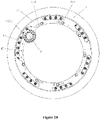
- variable pitch mechanism includes a variable pitch bearing and a variable pitch driving gear 30.
- the variable pitch bearing includes an inner ring of the bearing 21 and an outer ring of the bearing 20, the outer ring of the bearing 20 is securely mounted on a hub 1, a blade 3 is securely mounted on the inner ring 21 of the bearing. Teeth are formed on the inner circumference of the inner ring 21 of the bearing, the variable pitch driving gear 30 engages with the teeth of the inner ring 21 of the bearing, and the inner ring of the driving bearing 21 rotates relative to the hub 1, thereby adjusting a blade angle of the blade 3.
- variable pitch mechanism further includes a flange 4 mounted on the hub 1.
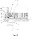
- a web 11 is formed on the inside of the hub 1, the flange 4 is mounted on the web 11, a driving motor 6 and a reducer 5 are mounted on the flange 4, and the variable pitch driving gear 30 is mounted at an end of an output shaft of the reducer 5, which maintains a meshing state with the inner ring 21 of the bearing.
- the web 11 extends a predetermined width from the hub 1 in a radial inward direction and has a predetermined distance in an axial direction from an axial end of the inner ring 21 of the variable pitch bearing.
- the flange 4 is mounted on the web 11. In the axial direction of the variable pitch bearing, the flange 4 is located between the web 11 and the inner ring 21 of the bearing, and the flange 4 is axially limited through the web 11 and the inner ring 21 of the bearing.
- the flange 4 When the flange 4 is limited only in the axial direction, the flange 4 can rotate in a circumferential direction, so that a mounting position of the flange 4 relative to the inner ring 21 of the bearing can be adjusted in the circumferential direction, thereby the variable pitch driving gear 30 can engage with teeth in different positions of the inner ring 21 of the bearing.
- the flange 4 is a circular ring, so that the flange 4 is easy to maintain a designed shape and size, is not easy to deform, avoids local stress, and causes uniform force on the inner ring 21 of the bearing.
- the flange 4 may also be a non-integral circular structure, that is, a part of the circular ring in the circumferential direction, if the design conditions are met.
- the non-integral circular structure is adopted, an axial and radial positioning of the flange 4 when rotating freely should be guaranteed and the flange of the non-integral circular structure when rotating freely should be prevented from falling off the web 11 of the hub 1 and the inner ring 21 of the bearing.
- a circular stop member 111 may be provided on the web 11 (please refer to Figure 4 ), so that an outer peripheral surface of the flange 4 is in clearance fit with the inner circumferential surface of the stop member 111.
- the inner circumferential surface of the stop member 111 may provide radial positioning of the flange 4.
- first through holes 114 may be provided on the web 11
- multiple second through holes 42 may be provided on the flange 4
- the second through hole 42 is preferably a threaded hole for facilitating bolt installation and disassembly and avoiding axial interference between the fixing bolt 841 and the inner ring 21 of the bearing.
- the fixing bolt 841 passes through the first through hole 114 and is threaded with the second through hole 42, so as to secure the flange 4 to the web 11 of the hub 1.
- the first through hole 114 may be designed as a slotted hole extending in a circumferential direction.
- a first through hole 114 may correspond to multiple second through holes 42 such that multiple second through holes 42 are exposed outwards through the first through hole 114, so as to provide the circumferential positioning of different positions of the flange 4 while facilitating the penetration of the fixing bolt 841.
- a first keyway 115 is provided from a radial inner side in a radially outward direction
- a second keyway 41 is provided from the radial inner side in a radially outward direction.
- first keyways 115 and second keyways 41 may be provided in the circumferential direction, and the number, position and size of the first keyways 115 and second keyways 41correspond to each other, so as to satisfy the position positioning of different meshing areas.
- the spaces between the multiple first keyways 115 and the second keyways 42 in the circumferential direction need to correspond to a rotation angle when different meshing positions are switched.
- a positioning key locking structure is further provided.
- a threaded hole penetrating the web 11 is formed on the web 11, and another threaded hole is also formed at the corresponding position of the positioning key 7, a locking bolt 851 is inserted from the axial outward of the web 11 into the positioning key 7 located in the positioning keyway 120, and the positioning key 7 is locked to prevent the positioning key 7 from falling off radially.
- a threaded hole 71 is formed at an outer end of the positioning key 7, and the threaded hole 71 extends a predetermined length in a radial direction.
- the locking bolt 851 may be disassembled first and then rotated into the threaded hole 71 through a threaded tap, and the positioning key 7 may be pulled out in a radially inward direction.
- a certain length of opening 112 may be provided in the hub web 11.
- the opening 112 it needs to avoid a high stress force area of the hub 1 and ensure that the mounting position of the variable pitch driving accessories of the hub 1 does not interfere, the length of the opening 112 (or the circumferential angle of the hub web 11) satisfies that the driving gear 30 of the reducer 5 and the gear ring of the inner ring 21 of the bearing are staggered from a single concentrated force tooth.
- the opening 112 may extend in a range of 10 degrees to 50 degrees in the circumferential direction of the variable pitch bearing.
- Figure 2A and 2B show schematic diagrams of engagement of the variable pitch driving gear with the inner ring 21 of the bearing in the first position and the second position, respectively.
- the variable pitch driving gear 30 engages with the teeth in the first position of the inner ring 21 of the bearing.
- a circumferential limit structure and a radial limit structure may be disassembled, for example, the fixing bolt 841, the locking bolt 851 and the positioning key 7 are disassembled, so that the rotation of the circumferential direction of the flange 4 is unrestricted.
- variable pitch driving gear 30 is then driven so that the variable pitch driving gear 30 moves along the inner circumference of the inner ring 21 of the bearing, thus driving the flange 4 to rotate at a certain angle in the circumferential direction, as shown in Figure 2B , the variable pitch driving gear 30 is staggered from the worn teeth and engaged with the teeth of the inner ring 21 of the bearing in the second position.
- first keyway 115 and the second keyway 41 correspond to each other to satisfy the position positioning of switching different meshing areas. For example, when the first position is switched into the second position, the first keyway 115 and the second keyway 41 match correspondingly exactly, so that the positioning key 7 may be inserted.
- the first through hole 114 on the web 11 and the second through hole 42 on the web 11 need to correspond exactly, so that the fixing bolt 841 is switched to the corresponding second through hole 42 and the flange 4 is re-secured to the web 11.
- the positioning key 7 is inserted into the positioning keyway 120 and secured by securing the flange 4 and the hub 1 through fixed bolts 841, the variable pitch motor 6 and the reducer 5 and the variable pitch driving gear 30 are securely mounted on the flange 4.
- the variable pitch driving gear 30 at the output end of the driving reducer 5 is engaged with the teeth of the inner ring 21 of the bearing.
- the concentrated meshing area of the gear ring is need to change.
- the impeller of the wind turbine is locked, at the same time, the inner ring 21 of the bearing and the outer ring of the bearing 20 are locked, the fixing bolt 841 between the flange 4 and the hub 1 is disassembled, the positioning key 7 is disassembled, and the variable pitch motor 6 is electrified to drive the variable pitch driving gear 30 at the output end of the driving reducer 5 to rotate. Because the inner ring 21 of the bearing is locked at this time, the variable pitch driving gear 30 drives the flange 4 to rotate during the meshing process between the variable pitch driving gear 30 and the inner ring 21 of the bearing.
- the motor 6 is stopped, the positioning key 7 is inserted into the positioning keyway 120, the locking bolt 851 is rotated, and the position of the positioning key 7 is secured.
- the fixing bolt 841 is installed in the first through hole 114 and the second through hole 42 on the flange 4, which realizes the securing of the flange 4.
- the flange 4 can rotate in a predetermined angle range.
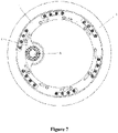
- the motor 6 mounted on the flange 4, and the reducer 5 are capable of self-rotating a certain stroke and do not interfere with the hub web 11, the opening 112 may not arrange on the web 11, as shown in Figures 6 and 7 , the motor 6 and the reducer 5 are located on the radial inner side of the hub web 11 and the flange can freely rotated and positioned within 360 degrees, thus the meshing position can be adjusted within an angle range of 360 degrees.
- the inner ring 21 of the bearing is connected to the root of the blade through fixing bolts 811 and nuts 813.
- multiple slotted holes 113 extending in the circumferential direction may be provided in the position corresponding to the web 11 and the fixing bolt 811, so that the fixing bolt 811 is exposed outwards.
- Multiple slotted holes 113 may be evenly distributed in the circumferential direction to provide a maintenance space for the fixing bolt 811 of the root of the blade. Rotating bearings are required for maintenance to expose target maintenance bolts.
- the situation of the replacement and maintenance of the variable pitch bearing caused by the long-term local wear and damage of the bearing ring can be avoided, and the service life and reliability of the bearing gear ring and the variable pitch driving gear ring can be greatly improved.
- the centralized meshing area of the gear ring can be transformed without disassembling the driving accessories such as the variable pitch motor and the reducer. Therefore, the operation is convenient, simple and low cost.
Landscapes
- Engineering & Computer Science (AREA)
- Life Sciences & Earth Sciences (AREA)
- Sustainable Development (AREA)
- Sustainable Energy (AREA)
- Chemical & Material Sciences (AREA)
- Combustion & Propulsion (AREA)
- Mechanical Engineering (AREA)
- General Engineering & Computer Science (AREA)
- Physics & Mathematics (AREA)
- Fluid Mechanics (AREA)
- Wind Motors (AREA)
- Mounting Of Bearings Or Others (AREA)
Claims (10)
- Verstellmechanismus für eine Windkraftanlage, wobei der Verstellmechanismus ein Verstelllager und ein Antriebszahnrad (30) umfasst, wobei das Verstelllager einen an einer Nabe (1) befestigten Außenring des Lagers (20) und einen mit einem Blatt (3) verbundenen Innenring (21) des Lagers umfasst, wobei eine Innenumfangsfläche des Innenrings (21) des Lagers mit Zähnen versehen ist, wobei der Verstellmechanismus des Weiteren einen Flansch (4) umfasst,
dadurch gekennzeichnet, dass
der Flansch (4) an der Nabe (1) angeordnet ist und koaxial zu dem Verstelllager angeordnet ist, dass das Antriebszahnrad (30) an dem Flansch (4) angebracht ist und mit den Zähnen an dem Innenring (21) des Lagers in Eingriff steht, und dass eine Montageposition des Flansches (4) an der Nabe (1) entlang einer Umfangsrichtung relativ zu dem Innenring (21) des Lagers durch das Drehen des Flansches um seine Achse einstellbar ist, wodurch ein Eingriffsbereich zwischen dem Innenring (21) des Lagers und dem Antriebszahnrad (30) verändert wird. - Verstellmechanismus nach Anspruch 1, wobei die Nabe (1) einen sich radial nach Innen erstreckenden Steg (11) umfasst, wobei der Flansch (4) an dem Steg (11) und relativ zu der Umfangsrichtung des Verstelllagers angebracht ist, und wobei der Flansch (4) eine Vielzahl von Montagepositionen an dem Steg (11) aufweist, wobei der Flansch (4) in eine beliebige der Vielzahl von Montagepositionen drehbar ist, wenn der Innenring (21) des Lagers befestigt ist.
- Verstellmechanismus nach Anspruch 2, wobei der Verstellmechanismus eine radiale Begrenzungsstruktur umfasst, wobei die radiale Begrenzungsstruktur ein an dem Steg (11) ausgebildetes Anschlagelement (111) umfasst, wobei eine Innenumfangsfläche des Anschlagelements (111) mit dem Umfang des Flansches (4) zusammenwirkt, und wobei eine radiale Position des Flansches (4) begrenzt ist.
- Verstellmechanismus nach Anspruch 3, wobei der Flansch (4) in einer axialen Richtung des Verstelllagers zwischen dem Steg (11) und dem Innenring (21) des Lagers angebracht ist.
- Verstellmechanismus nach Anspruch 4, wobei eine Vielzahl von ersten Durchgangslöchern (114) an dem Steg (11) vorgesehen ist, wobei eine Vielzahl von zweiten Durchgangslöchern (42) an dem Flansch (4) vorgesehen ist, wobei ein Befestigungsbolzen (841) durch das erste Durchgangsloch (114) und das zweite Durchgangsloch (42) hindurchgeht, um den Flansch (4) an der Nabe (1) zu befestigen, wobei das erste Durchgangsloch (114) ein sich entlang der Umfangsrichtung erstreckendes Langloch ist, und wobei eines der ersten Durchgangslöcher (114) eine Vielzahl von zweiten Durchgangslöchern (42) freilegt.
- Verstellmechanismus nach Anspruch 2, wobei der Verstellmechanismus des Weiteren eine Umfangsbegrenzungsstruktur zum Begrenzen einer Position des Flansches (4) in der Umfangsrichtung umfasst, wobei die Umfangsbegrenzungsstruktur einen Positionierungskeil (7), eine Vielzahl von ersten Keilnuten (115) und eine Vielzahl von zweiten Keilnuten (41) umfasst,
wobei die Vielzahl von ersten Keilnuten (115) an einer Oberfläche des Stegs (11) in Kontakt mit dem Flansch (4) angeordnet ist, und wobei die Vielzahl von zweiten Keilnuten (41) an der Oberfläche des Flansches (4) in Kontakt mit dem Steg (11) angeordnet ist, wobei, wenn eine erste Keilnut (115) einer zweiten Keilnut (41) zur Ausbildung einer Positionierungskeilnut (120) zugewandt ist, der Positionierungskeil (7) von einer radialen Innenseite des Flansches (4) in die Positionierungskeilnut (120) eingeführt wird, um die Umfangsrichtung des Flansches (4) zu begrenzen. - Verstellmechanismus nach Anspruch 6, wobei der Verstellmechanismus des Weiteren eine Positionierungskeil-Verriegelungstruktur umfasst, wobei die Positionierungskeil-Verriegelungstruktur einen Verriegelungsbolzen (851), ein erstes Verriegelungsloch, das an dem Steg (11) angeordnet ist, sich axial erstreckt und in Verbindung mit der ersten Keilnut (115) steht, und ein sich axial an dem Positionierungskeil (7) erstreckendes zweites Verriegelungsloch umfasst, wobei das erste Verriegelungsloch dem zweiten Verriegelungsloch entspricht, wobei der Verriegelungsbolzen (851) durch das erste Verriegelungsloch und das zweite Verrieglungsloch hindurchgeht, um den Positionierungskeil (7) in der Positionierungskeilnut (120) zu verriegeln, wobei das zweite Verriegelungsloch ein Gewindeloch ist.
- Verstellmechanismus nach Anspruch 2, wobei eine Öffnung (112) an dem Steg (11) vorgesehen ist, wobei das Antriebszahnrad (30) mit dem Innenring (21) des Lagers in einem der Öffnung (112) entsprechenden Positionsbereich in Eingriff steht, und wobei die Vielzahl von Montagepositionen in dem Positionsbereich angeordnet ist.
- Verstellmechanismus nach Anspruch 8, wobei sich die Öffnung (112) in einem Bereich von 10 Grad bis 50 Grad in der Umfangsrichtung des Verstelllagers erstreckt.
- Windkraftanlage, wobei die Windkraftanlage einen Verstellmechanismus umfasst, wie er in einem der Ansprüche 1 bis 9 beschrieben ist.
Applications Claiming Priority (2)
| Application Number | Priority Date | Filing Date | Title |
|---|---|---|---|
| CN201810679909.2A CN108775273B (zh) | 2018-06-27 | 2018-06-27 | 变桨机构及风力发电机组 |
| PCT/CN2018/112873 WO2020000824A1 (zh) | 2018-06-27 | 2018-10-31 | 变桨机构及风力发电机组 |
Publications (3)
| Publication Number | Publication Date |
|---|---|
| EP3608537A1 EP3608537A1 (de) | 2020-02-12 |
| EP3608537A4 EP3608537A4 (de) | 2020-06-03 |
| EP3608537B1 true EP3608537B1 (de) | 2022-03-30 |
Family
ID=64030407
Family Applications (1)
| Application Number | Title | Priority Date | Filing Date |
|---|---|---|---|
| EP18909267.9A Active EP3608537B1 (de) | 2018-06-27 | 2018-10-31 | Neigungsverstellungsmechanismus und windturbine |
Country Status (5)
| Country | Link |
|---|---|
| US (1) | US11460001B2 (de) |
| EP (1) | EP3608537B1 (de) |
| CN (1) | CN108775273B (de) |
| AU (1) | AU2018412623B2 (de) |
| WO (1) | WO2020000824A1 (de) |
Families Citing this family (10)
| Publication number | Priority date | Publication date | Assignee | Title |
|---|---|---|---|---|
| CN108775273B (zh) * | 2018-06-27 | 2019-08-06 | 新疆金风科技股份有限公司 | 变桨机构及风力发电机组 |
| CN110242499B (zh) * | 2019-07-17 | 2022-11-11 | 北京金风科创风电设备有限公司 | 变桨驱动模组、叶轮系统、风力发电机组及运输方法 |
| CN111255631A (zh) * | 2020-02-15 | 2020-06-09 | 吴志华 | 一种风力发电机变桨装置 |
| CN113446150B (zh) * | 2020-03-27 | 2024-02-06 | 乌鲁木齐金风天翼风电有限公司 | 变桨系统和风力发电机组 |
| CN111963392B (zh) * | 2020-07-22 | 2021-12-10 | 明阳智慧能源集团股份公司 | 一种解决风力发电机组变桨轴承零位齿磨损的方法 |
| CN112594145B (zh) * | 2020-08-28 | 2022-08-12 | 河北新天科创新能源技术有限公司 | 一种用于风力发电机组变桨轴承轴向旋转位置调整方法 |
| CN114109720B (zh) * | 2021-12-31 | 2023-04-25 | 中国华能集团清洁能源技术研究院有限公司 | 一种水平轴风力机风轮增功提效装置 |
| CN114235415B (zh) | 2022-02-28 | 2022-06-03 | 浙江大学 | 基于神经网络的风力发电机变桨轴承故障诊断方法及装置 |
| CN116398370A (zh) * | 2023-04-06 | 2023-07-07 | 中国船舶重工集团海装风电股份有限公司 | 一种风力发电机组及其安装方法 |
| CN118911918B (zh) * | 2024-10-08 | 2025-02-25 | 国能联合动力技术(连云港)有限公司 | 一种用于风电机组的叶片锁紧装置 |
Family Cites Families (10)
| Publication number | Priority date | Publication date | Assignee | Title |
|---|---|---|---|---|
| DE102008052411B3 (de) * | 2008-10-21 | 2010-04-29 | Aerodyn Energiesysteme Gmbh | Lageveränderlicher Pitch-Antrieb |
| US8092171B2 (en) * | 2009-09-30 | 2012-01-10 | General Electric Company | Systems and methods for assembling a pitch assembly for use in a wind turbine |
| CN201757027U (zh) * | 2010-08-19 | 2011-03-09 | 广东东兴风盈风电设备制造有限公司 | 一种风力发电机变桨连接装置 |
| WO2012029102A1 (ja) * | 2010-08-30 | 2012-03-08 | 三菱重工業株式会社 | 風力発電装置 |
| EP2458200B1 (de) * | 2010-11-30 | 2015-10-07 | ALSTOM Renewable Technologies | Windturbinenrotor mit Blattverstellmechanismus und eine Reparaturmethode dafür |
| ES2488341T3 (es) * | 2011-09-30 | 2014-08-26 | Alstom Renovables España, S.L. | Rotor de aerogenerador |
| CN202273806U (zh) * | 2011-10-11 | 2012-06-13 | 华锐风电科技(集团)股份有限公司 | 一种风力发电机变桨驱动系统 |
| US9803620B2 (en) * | 2011-12-30 | 2017-10-31 | Vestas Wind Systems A/S | Pitch system for a wind turbine |
| US9951815B2 (en) * | 2013-06-27 | 2018-04-24 | General Electric Company | Pitch bearing assembly with stiffener |
| CN108775273B (zh) * | 2018-06-27 | 2019-08-06 | 新疆金风科技股份有限公司 | 变桨机构及风力发电机组 |
-
2018
- 2018-06-27 CN CN201810679909.2A patent/CN108775273B/zh active Active
- 2018-10-31 WO PCT/CN2018/112873 patent/WO2020000824A1/zh not_active Ceased
- 2018-10-31 EP EP18909267.9A patent/EP3608537B1/de active Active
- 2018-10-31 US US16/612,505 patent/US11460001B2/en active Active
- 2018-10-31 AU AU2018412623A patent/AU2018412623B2/en active Active
Also Published As
| Publication number | Publication date |
|---|---|
| US11460001B2 (en) | 2022-10-04 |
| EP3608537A4 (de) | 2020-06-03 |
| CN108775273A (zh) | 2018-11-09 |
| AU2018412623A1 (en) | 2020-01-16 |
| WO2020000824A1 (zh) | 2020-01-02 |
| EP3608537A1 (de) | 2020-02-12 |
| AU2018412623B2 (en) | 2021-10-21 |
| US20210332800A1 (en) | 2021-10-28 |
| CN108775273B (zh) | 2019-08-06 |
Similar Documents
| Publication | Publication Date | Title |
|---|---|---|
| EP3608537B1 (de) | Neigungsverstellungsmechanismus und windturbine | |
| EP2458200B1 (de) | Windturbinenrotor mit Blattverstellmechanismus und eine Reparaturmethode dafür | |
| EP2730779B1 (de) | Azimutbremsen für Windturbinen | |
| EP2306002B1 (de) | Systeme und Methoden, um eine Anstellwinkelregelung für den Gebrauch in einer Windturbine zusammenzustellen | |
| EP2253840B1 (de) | Windturbine und Einrichtung zur Verstellung des Blatteinstellwinkels | |
| WO2017054679A1 (zh) | 风力发电机组用轴承支撑装置及安装方法、风力发电机组 | |
| CN107294273B (zh) | 借助于转动装置的发电机的旋转运动控制 | |
| EP3798460B1 (de) | Antriebsstrang einer windturbine mit einem drehmomentbegrenzer, windturbine | |
| BR112017000912B1 (pt) | Caixa de engrenagens planetária | |
| EP3530939B1 (de) | Ersatzverfahren für radialdichtungen von windturbinenhauptlagern | |
| EP2759702A1 (de) | Vorrichtung zur stromerzeugung aus erneuerbarer energie und betriebsverfahren dafür | |
| EP4156475B1 (de) | Rotorverriegelung für eine elektrische maschine | |
| EP3999741B1 (de) | Verbesserungen in bezug auf windturbinenhauptrotordrehsysteme | |
| EP2602481B1 (de) | Anordnung zum Fixieren der Anstellwinkel eines Rotorblatts einer Windkraftanlage | |
| EP3587804B1 (de) | Windturbinenstromerzeugungsanlage und wartungsverfahren dafür | |
| EP3798467A1 (de) | Antriebsstrang einer windturbine mit einer kupplungswelle zum ausgleich von rundlauftoleranzen und fehlausrichtung einer getriebeausgangsachse und einer generatordrehachse | |
| JPS6354144B2 (de) | ||
| RU2719166C1 (ru) | Арретирующее устройство для ротора ветроэнергетической установки | |
| CN219654746U (zh) | 一种便于拆卸的叶轮结构及涡轮机 | |
| KR20130061808A (ko) | 풍력발전기의 블레이드 피치구동기구 | |
| KR200486893Y1 (ko) | 윤활유 회수구조를 포함하는 조타장치 | |
| KR20240023163A (ko) | 풍력 터빈 요 모터용 서비스 브레이크 | |
| CN119895177A (zh) | 风力涡轮机的齿轮箱的组件,装置,套件,风力涡轮机的齿轮箱,运输齿轮箱的组件的方法及组装风力涡轮机的方法 |
Legal Events
| Date | Code | Title | Description |
|---|---|---|---|
| STAA | Information on the status of an ep patent application or granted ep patent |
Free format text: STATUS: UNKNOWN |
|
| STAA | Information on the status of an ep patent application or granted ep patent |
Free format text: STATUS: THE INTERNATIONAL PUBLICATION HAS BEEN MADE |
|
| PUAI | Public reference made under article 153(3) epc to a published international application that has entered the european phase |
Free format text: ORIGINAL CODE: 0009012 |
|
| STAA | Information on the status of an ep patent application or granted ep patent |
Free format text: STATUS: REQUEST FOR EXAMINATION WAS MADE |
|
| 17P | Request for examination filed |
Effective date: 20191015 |
|
| AK | Designated contracting states |
Kind code of ref document: A1 Designated state(s): AL AT BE BG CH CY CZ DE DK EE ES FI FR GB GR HR HU IE IS IT LI LT LU LV MC MK MT NL NO PL PT RO RS SE SI SK SM TR |
|
| A4 | Supplementary search report drawn up and despatched |
Effective date: 20200506 |
|
| RIC1 | Information provided on ipc code assigned before grant |
Ipc: F03D 7/02 20060101ALI20200428BHEP Ipc: F03D 7/00 20060101AFI20200428BHEP Ipc: F03D 80/70 20160101ALI20200428BHEP |
|
| GRAP | Despatch of communication of intention to grant a patent |
Free format text: ORIGINAL CODE: EPIDOSNIGR1 |
|
| STAA | Information on the status of an ep patent application or granted ep patent |
Free format text: STATUS: GRANT OF PATENT IS INTENDED |
|
| INTG | Intention to grant announced |
Effective date: 20211110 |
|
| GRAS | Grant fee paid |
Free format text: ORIGINAL CODE: EPIDOSNIGR3 |
|
| GRAA | (expected) grant |
Free format text: ORIGINAL CODE: 0009210 |
|
| STAA | Information on the status of an ep patent application or granted ep patent |
Free format text: STATUS: THE PATENT HAS BEEN GRANTED |
|
| AK | Designated contracting states |
Kind code of ref document: B1 Designated state(s): AL AT BE BG CH CY CZ DE DK EE ES FI FR GB GR HR HU IE IS IT LI LT LU LV MC MK MT NL NO PL PT RO RS SE SI SK SM TR |
|
| REG | Reference to a national code |
Ref country code: GB Ref legal event code: FG4D |
|
| REG | Reference to a national code |
Ref country code: CH Ref legal event code: EP |
|
| REG | Reference to a national code |
Ref country code: DE Ref legal event code: R096 Ref document number: 602018033180 Country of ref document: DE |
|
| REG | Reference to a national code |
Ref country code: AT Ref legal event code: REF Ref document number: 1479412 Country of ref document: AT Kind code of ref document: T Effective date: 20220415 |
|
| REG | Reference to a national code |
Ref country code: IE Ref legal event code: FG4D |
|
| REG | Reference to a national code |
Ref country code: LT Ref legal event code: MG9D |
|
| PG25 | Lapsed in a contracting state [announced via postgrant information from national office to epo] |
Ref country code: SE Free format text: LAPSE BECAUSE OF FAILURE TO SUBMIT A TRANSLATION OF THE DESCRIPTION OR TO PAY THE FEE WITHIN THE PRESCRIBED TIME-LIMIT Effective date: 20220330 Ref country code: RS Free format text: LAPSE BECAUSE OF FAILURE TO SUBMIT A TRANSLATION OF THE DESCRIPTION OR TO PAY THE FEE WITHIN THE PRESCRIBED TIME-LIMIT Effective date: 20220330 Ref country code: NO Free format text: LAPSE BECAUSE OF FAILURE TO SUBMIT A TRANSLATION OF THE DESCRIPTION OR TO PAY THE FEE WITHIN THE PRESCRIBED TIME-LIMIT Effective date: 20220630 Ref country code: LT Free format text: LAPSE BECAUSE OF FAILURE TO SUBMIT A TRANSLATION OF THE DESCRIPTION OR TO PAY THE FEE WITHIN THE PRESCRIBED TIME-LIMIT Effective date: 20220330 Ref country code: HR Free format text: LAPSE BECAUSE OF FAILURE TO SUBMIT A TRANSLATION OF THE DESCRIPTION OR TO PAY THE FEE WITHIN THE PRESCRIBED TIME-LIMIT Effective date: 20220330 Ref country code: BG Free format text: LAPSE BECAUSE OF FAILURE TO SUBMIT A TRANSLATION OF THE DESCRIPTION OR TO PAY THE FEE WITHIN THE PRESCRIBED TIME-LIMIT Effective date: 20220630 |
|
| REG | Reference to a national code |
Ref country code: NL Ref legal event code: MP Effective date: 20220330 |
|
| REG | Reference to a national code |
Ref country code: AT Ref legal event code: MK05 Ref document number: 1479412 Country of ref document: AT Kind code of ref document: T Effective date: 20220330 |
|
| REG | Reference to a national code |
Ref country code: GR Ref legal event code: EP Ref document number: 20220401169 Country of ref document: GR Effective date: 20220707 |
|
| PG25 | Lapsed in a contracting state [announced via postgrant information from national office to epo] |
Ref country code: LV Free format text: LAPSE BECAUSE OF FAILURE TO SUBMIT A TRANSLATION OF THE DESCRIPTION OR TO PAY THE FEE WITHIN THE PRESCRIBED TIME-LIMIT Effective date: 20220330 Ref country code: FI Free format text: LAPSE BECAUSE OF FAILURE TO SUBMIT A TRANSLATION OF THE DESCRIPTION OR TO PAY THE FEE WITHIN THE PRESCRIBED TIME-LIMIT Effective date: 20220330 |
|
| PG25 | Lapsed in a contracting state [announced via postgrant information from national office to epo] |
Ref country code: NL Free format text: LAPSE BECAUSE OF FAILURE TO SUBMIT A TRANSLATION OF THE DESCRIPTION OR TO PAY THE FEE WITHIN THE PRESCRIBED TIME-LIMIT Effective date: 20220330 |
|
| PG25 | Lapsed in a contracting state [announced via postgrant information from national office to epo] |
Ref country code: SM Free format text: LAPSE BECAUSE OF FAILURE TO SUBMIT A TRANSLATION OF THE DESCRIPTION OR TO PAY THE FEE WITHIN THE PRESCRIBED TIME-LIMIT Effective date: 20220330 Ref country code: SK Free format text: LAPSE BECAUSE OF FAILURE TO SUBMIT A TRANSLATION OF THE DESCRIPTION OR TO PAY THE FEE WITHIN THE PRESCRIBED TIME-LIMIT Effective date: 20220330 Ref country code: RO Free format text: LAPSE BECAUSE OF FAILURE TO SUBMIT A TRANSLATION OF THE DESCRIPTION OR TO PAY THE FEE WITHIN THE PRESCRIBED TIME-LIMIT Effective date: 20220330 Ref country code: PT Free format text: LAPSE BECAUSE OF FAILURE TO SUBMIT A TRANSLATION OF THE DESCRIPTION OR TO PAY THE FEE WITHIN THE PRESCRIBED TIME-LIMIT Effective date: 20220801 Ref country code: ES Free format text: LAPSE BECAUSE OF FAILURE TO SUBMIT A TRANSLATION OF THE DESCRIPTION OR TO PAY THE FEE WITHIN THE PRESCRIBED TIME-LIMIT Effective date: 20220330 Ref country code: EE Free format text: LAPSE BECAUSE OF FAILURE TO SUBMIT A TRANSLATION OF THE DESCRIPTION OR TO PAY THE FEE WITHIN THE PRESCRIBED TIME-LIMIT Effective date: 20220330 Ref country code: CZ Free format text: LAPSE BECAUSE OF FAILURE TO SUBMIT A TRANSLATION OF THE DESCRIPTION OR TO PAY THE FEE WITHIN THE PRESCRIBED TIME-LIMIT Effective date: 20220330 Ref country code: AT Free format text: LAPSE BECAUSE OF FAILURE TO SUBMIT A TRANSLATION OF THE DESCRIPTION OR TO PAY THE FEE WITHIN THE PRESCRIBED TIME-LIMIT Effective date: 20220330 |
|
| PG25 | Lapsed in a contracting state [announced via postgrant information from national office to epo] |
Ref country code: PL Free format text: LAPSE BECAUSE OF FAILURE TO SUBMIT A TRANSLATION OF THE DESCRIPTION OR TO PAY THE FEE WITHIN THE PRESCRIBED TIME-LIMIT Effective date: 20220330 Ref country code: IS Free format text: LAPSE BECAUSE OF FAILURE TO SUBMIT A TRANSLATION OF THE DESCRIPTION OR TO PAY THE FEE WITHIN THE PRESCRIBED TIME-LIMIT Effective date: 20220730 Ref country code: AL Free format text: LAPSE BECAUSE OF FAILURE TO SUBMIT A TRANSLATION OF THE DESCRIPTION OR TO PAY THE FEE WITHIN THE PRESCRIBED TIME-LIMIT Effective date: 20220330 |
|
| REG | Reference to a national code |
Ref country code: DE Ref legal event code: R097 Ref document number: 602018033180 Country of ref document: DE |
|
| PG25 | Lapsed in a contracting state [announced via postgrant information from national office to epo] |
Ref country code: DK Free format text: LAPSE BECAUSE OF FAILURE TO SUBMIT A TRANSLATION OF THE DESCRIPTION OR TO PAY THE FEE WITHIN THE PRESCRIBED TIME-LIMIT Effective date: 20220330 |
|
| PLBE | No opposition filed within time limit |
Free format text: ORIGINAL CODE: 0009261 |
|
| STAA | Information on the status of an ep patent application or granted ep patent |
Free format text: STATUS: NO OPPOSITION FILED WITHIN TIME LIMIT |
|
| 26N | No opposition filed |
Effective date: 20230103 |
|
| PG25 | Lapsed in a contracting state [announced via postgrant information from national office to epo] |
Ref country code: SI Free format text: LAPSE BECAUSE OF FAILURE TO SUBMIT A TRANSLATION OF THE DESCRIPTION OR TO PAY THE FEE WITHIN THE PRESCRIBED TIME-LIMIT Effective date: 20220330 Ref country code: MC Free format text: LAPSE BECAUSE OF FAILURE TO SUBMIT A TRANSLATION OF THE DESCRIPTION OR TO PAY THE FEE WITHIN THE PRESCRIBED TIME-LIMIT Effective date: 20220330 |
|
| REG | Reference to a national code |
Ref country code: CH Ref legal event code: PL |
|
| REG | Reference to a national code |
Ref country code: BE Ref legal event code: MM Effective date: 20221031 |
|
| GBPC | Gb: european patent ceased through non-payment of renewal fee |
Effective date: 20221031 |
|
| PG25 | Lapsed in a contracting state [announced via postgrant information from national office to epo] |
Ref country code: LU Free format text: LAPSE BECAUSE OF NON-PAYMENT OF DUE FEES Effective date: 20221031 |
|
| PG25 | Lapsed in a contracting state [announced via postgrant information from national office to epo] |
Ref country code: LI Free format text: LAPSE BECAUSE OF NON-PAYMENT OF DUE FEES Effective date: 20221031 Ref country code: CH Free format text: LAPSE BECAUSE OF NON-PAYMENT OF DUE FEES Effective date: 20221031 |
|
| PG25 | Lapsed in a contracting state [announced via postgrant information from national office to epo] |
Ref country code: BE Free format text: LAPSE BECAUSE OF NON-PAYMENT OF DUE FEES Effective date: 20221031 |
|
| PG25 | Lapsed in a contracting state [announced via postgrant information from national office to epo] |
Ref country code: IE Free format text: LAPSE BECAUSE OF NON-PAYMENT OF DUE FEES Effective date: 20221031 Ref country code: GB Free format text: LAPSE BECAUSE OF NON-PAYMENT OF DUE FEES Effective date: 20221031 |
|
| REG | Reference to a national code |
Ref country code: DE Ref legal event code: R081 Ref document number: 602018033180 Country of ref document: DE Owner name: GOLDWIND SCIENCE & TECHNOLOGY CO., LTD., URUMQ, CN Free format text: FORMER OWNER: XINJIANG GOLDWIND SCIENCE & TECHNOLOGY CO., LTD., URUMQI, XINJIANG, CN |
|
| PG25 | Lapsed in a contracting state [announced via postgrant information from national office to epo] |
Ref country code: HU Free format text: LAPSE BECAUSE OF FAILURE TO SUBMIT A TRANSLATION OF THE DESCRIPTION OR TO PAY THE FEE WITHIN THE PRESCRIBED TIME-LIMIT; INVALID AB INITIO Effective date: 20181031 |
|
| PG25 | Lapsed in a contracting state [announced via postgrant information from national office to epo] |
Ref country code: CY Free format text: LAPSE BECAUSE OF FAILURE TO SUBMIT A TRANSLATION OF THE DESCRIPTION OR TO PAY THE FEE WITHIN THE PRESCRIBED TIME-LIMIT Effective date: 20220330 |
|
| PG25 | Lapsed in a contracting state [announced via postgrant information from national office to epo] |
Ref country code: MK Free format text: LAPSE BECAUSE OF FAILURE TO SUBMIT A TRANSLATION OF THE DESCRIPTION OR TO PAY THE FEE WITHIN THE PRESCRIBED TIME-LIMIT Effective date: 20220330 |
|
| PG25 | Lapsed in a contracting state [announced via postgrant information from national office to epo] |
Ref country code: MT Free format text: LAPSE BECAUSE OF FAILURE TO SUBMIT A TRANSLATION OF THE DESCRIPTION OR TO PAY THE FEE WITHIN THE PRESCRIBED TIME-LIMIT Effective date: 20220330 |
|
| PGFP | Annual fee paid to national office [announced via postgrant information from national office to epo] |
Ref country code: GR Payment date: 20250911 Year of fee payment: 8 |
|
| PGFP | Annual fee paid to national office [announced via postgrant information from national office to epo] |
Ref country code: IT Payment date: 20250922 Year of fee payment: 8 |
|
| PGFP | Annual fee paid to national office [announced via postgrant information from national office to epo] |
Ref country code: FR Payment date: 20250908 Year of fee payment: 8 |
|
| PG25 | Lapsed in a contracting state [announced via postgrant information from national office to epo] |
Ref country code: TR Free format text: LAPSE BECAUSE OF FAILURE TO SUBMIT A TRANSLATION OF THE DESCRIPTION OR TO PAY THE FEE WITHIN THE PRESCRIBED TIME-LIMIT Effective date: 20220330 |
|
| PGFP | Annual fee paid to national office [announced via postgrant information from national office to epo] |
Ref country code: DE Payment date: 20250902 Year of fee payment: 8 |