EP3608229A1 - Module optimise pour cockpit d'aeronef - Google Patents
Module optimise pour cockpit d'aeronef Download PDFInfo
- Publication number
- EP3608229A1 EP3608229A1 EP19185632.7A EP19185632A EP3608229A1 EP 3608229 A1 EP3608229 A1 EP 3608229A1 EP 19185632 A EP19185632 A EP 19185632A EP 3608229 A1 EP3608229 A1 EP 3608229A1
- Authority
- EP
- European Patent Office
- Prior art keywords
- air
- cockpit
- module
- dashboard
- module according
- Prior art date
- Legal status (The legal status is an assumption and is not a legal conclusion. Google has not performed a legal analysis and makes no representation as to the accuracy of the status listed.)
- Granted
Links
Images



Classifications
-
- B—PERFORMING OPERATIONS; TRANSPORTING
- B64—AIRCRAFT; AVIATION; COSMONAUTICS
- B64D—EQUIPMENT FOR FITTING IN OR TO AIRCRAFT; FLIGHT SUITS; PARACHUTES; ARRANGEMENT OR MOUNTING OF POWER PLANTS OR PROPULSION TRANSMISSIONS IN AIRCRAFT
- B64D13/00—Arrangements or adaptations of air-treatment apparatus for aircraft crew or passengers, or freight space
- B64D13/06—Arrangements or adaptations of air-treatment apparatus for aircraft crew or passengers, or freight space the air being conditioned
-
- B—PERFORMING OPERATIONS; TRANSPORTING
- B64—AIRCRAFT; AVIATION; COSMONAUTICS
- B64C—AEROPLANES; HELICOPTERS
- B64C1/00—Fuselages; Constructional features common to fuselages, wings, stabilising surfaces or the like
- B64C1/14—Windows; Doors; Hatch covers or access panels; Surrounding frame structures; Canopies; Windscreens accessories therefor, e.g. pressure sensors, water deflectors, hinges, seals, handles, latches, windscreen wipers
- B64C1/1476—Canopies; Windscreens or similar transparent elements
-
- B—PERFORMING OPERATIONS; TRANSPORTING
- B64—AIRCRAFT; AVIATION; COSMONAUTICS
- B64D—EQUIPMENT FOR FITTING IN OR TO AIRCRAFT; FLIGHT SUITS; PARACHUTES; ARRANGEMENT OR MOUNTING OF POWER PLANTS OR PROPULSION TRANSMISSIONS IN AIRCRAFT
- B64D13/00—Arrangements or adaptations of air-treatment apparatus for aircraft crew or passengers, or freight space
- B64D13/06—Arrangements or adaptations of air-treatment apparatus for aircraft crew or passengers, or freight space the air being conditioned
- B64D13/08—Arrangements or adaptations of air-treatment apparatus for aircraft crew or passengers, or freight space the air being conditioned the air being heated or cooled
-
- B—PERFORMING OPERATIONS; TRANSPORTING
- B64—AIRCRAFT; AVIATION; COSMONAUTICS
- B64D—EQUIPMENT FOR FITTING IN OR TO AIRCRAFT; FLIGHT SUITS; PARACHUTES; ARRANGEMENT OR MOUNTING OF POWER PLANTS OR PROPULSION TRANSMISSIONS IN AIRCRAFT
- B64D43/00—Arrangements or adaptations of instruments
-
- B—PERFORMING OPERATIONS; TRANSPORTING
- B64—AIRCRAFT; AVIATION; COSMONAUTICS
- B64F—GROUND OR AIRCRAFT-CARRIER-DECK INSTALLATIONS SPECIALLY ADAPTED FOR USE IN CONNECTION WITH AIRCRAFT; DESIGNING, MANUFACTURING, ASSEMBLING, CLEANING, MAINTAINING OR REPAIRING AIRCRAFT, NOT OTHERWISE PROVIDED FOR; HANDLING, TRANSPORTING, TESTING OR INSPECTING AIRCRAFT COMPONENTS, NOT OTHERWISE PROVIDED FOR
- B64F5/00—Designing, manufacturing, assembling, cleaning, maintaining or repairing aircraft, not otherwise provided for; Handling, transporting, testing or inspecting aircraft components, not otherwise provided for
- B64F5/10—Manufacturing or assembling aircraft, e.g. jigs therefor
-
- B—PERFORMING OPERATIONS; TRANSPORTING
- B64—AIRCRAFT; AVIATION; COSMONAUTICS
- B64D—EQUIPMENT FOR FITTING IN OR TO AIRCRAFT; FLIGHT SUITS; PARACHUTES; ARRANGEMENT OR MOUNTING OF POWER PLANTS OR PROPULSION TRANSMISSIONS IN AIRCRAFT
- B64D13/00—Arrangements or adaptations of air-treatment apparatus for aircraft crew or passengers, or freight space
- B64D13/06—Arrangements or adaptations of air-treatment apparatus for aircraft crew or passengers, or freight space the air being conditioned
- B64D2013/0603—Environmental Control Systems
- B64D2013/0625—Environmental Control Systems comprising means for distribution effusion of conditioned air in the cabin
-
- B—PERFORMING OPERATIONS; TRANSPORTING
- B64—AIRCRAFT; AVIATION; COSMONAUTICS
- B64D—EQUIPMENT FOR FITTING IN OR TO AIRCRAFT; FLIGHT SUITS; PARACHUTES; ARRANGEMENT OR MOUNTING OF POWER PLANTS OR PROPULSION TRANSMISSIONS IN AIRCRAFT
- B64D13/00—Arrangements or adaptations of air-treatment apparatus for aircraft crew or passengers, or freight space
- B64D13/06—Arrangements or adaptations of air-treatment apparatus for aircraft crew or passengers, or freight space the air being conditioned
- B64D2013/0603—Environmental Control Systems
- B64D2013/0662—Environmental Control Systems with humidity control
Definitions
- the invention relates to the field of assembly of the various components of an aircraft. It relates more specifically to the cockpit of an aircraft, and the assembly of its various equipment.
- the invention preferably applies to commercial aircraft.
- the cockpit of an aircraft is conventionally delimited by a framework which forms its structural part.
- Equipment is attached to this cockpit frame, such as a dashboard, also known as “MIP” (from the English “ Main Instrument Panel”).
- the cockpit is also equipped with many components belonging to an air conditioning system, and whose assembly on the cockpit frame generates a long assembly time.
- This assembly time dedicated to the assembly of the air system components on the cockpit frame is added to that required for the assembly of all the other components of the cockpit, such as systems, fittings, etc.
- the overall duration of the cockpit assembly is impacted by the difficulty of access to the fixing points of certain components on the frame. These attachment points are sometimes located in dense areas, making it difficult for operators to intervene.
- the invention thus breaks with the prior art by relating the air conditioning distribution unit to the dashboard, so as to form the same module.
- the assembly of the cockpit comprising such a module is thereby simplified, since the number of elements to be installed on the cockpit frame is advantageously reduced.
- the air conditioning distribution block running along and being integral with the rear face of the dashboard, these two components stiffen. This leads to an optimized mass and overall dimensions for the module, with the consequence of greater ease of assembly contributing to further improving the production rates.
- the invention preferably provides at least one of the following optional technical characteristics, taken individually or in combination.
- the air outlet of at least one of the air distribution channels is equipped with an air flow control valve.
- the air outlet of at least one of the air distribution channels is connected to a connector, the latter preferably being equipped with an air diffuser and / or an air heater.
- the block air distributor and the excess air collector are adjacent to two lateral ends of the dashboard, respectively.
- the air distribution channels are stacked on top of each other in a direction of the height of the dashboard, and arranged between the air distributor and excess air collector.
- Each air distribution channel has a curvature substantially identical locally to a curvature of the dashboard.
- the module includes a thermal insulation cover for the air distribution block, the latter being enclosed between the dashboard and the thermal insulation cover.
- the thermal insulation cover carries at least one air diffuser associated with at least one of the air distribution channels.
- the thermal insulation cover carries at least one motor for actuating at least one air flow regulation valve associated with at least one of the air distribution channels, each motor being preferably brought to the level d 'an upper portion of the thermal insulation cover.
- the module has an air inlet mouth connected to the air distributor, as well as an excess air outlet mouth connected to the excess air collector.
- the dashboard and the air distribution unit are made in one piece.
- the module comprises at least one screen carried by the dashboard, the screen preferably being a screen with organic light-emitting diodes.
- the invention also relates to an aircraft cockpit comprising a frame and such a module fixed to the cockpit frame, preferably on a structural windshield frame.
- the invention also relates to an aircraft comprising such a cockpit.
- It preferably comprises a lower front compartment located under a cockpit floor and under a passenger cabin floor, the lower front compartment housing electrical cabinets arranged aft with respect to a rear cockpit wall, and it is configured so that the the air escaping from the excess air collector of the cockpit module is introduced into the lower front compartment.
- the subject of the invention is a method of assembling such a cockpit, comprising a step of fixing the module on the cockpit frame.
- an aircraft 100 of the commercial aircraft type comprising two wings 2 (only one visible on the figure 1 ) attached to a fuselage 3 and each carrying a turbomachine 1 of the double-flow type, such as a turbojet.
- a front tip 6 is provided which is specific to the present invention, and a preferred embodiment of which will now be described with reference to the following figures.
- the direction X corresponds to the longitudinal direction of the aircraft, this direction also corresponding to the longitudinal direction of the front point 6, as well as to that of the cockpit 8 defined by this point .
- the direction Y corresponds to the lateral or transverse direction of the aircraft, this direction also corresponding to the lateral direction of the front point 6, as well as to that of the cockpit 8.
- the direction Z corresponds to the vertical or height direction, these three directions X, Y, Z being orthogonal to each other.
- the terms “front” and “rear” are to be considered in relation to a direction of advance of the aircraft, following the thrust of the turbomachines.
- the front tip 6 of the aircraft is shown in more detail, and in particular its cockpit 8 which here has the particularity of having a rather reduced volume compared to conventional solutions.
- it provides a pilot seat 10 centered in the cockpit in direction Y to accommodate the pilot, as well as a co-pilot seat 12 offset from the pilot seat 10 rearward in direction X and to the right in direction Y.
- the reduction in the volume of the cockpit is motivated by economic reasons, namely by the desire to increase the volume of the passenger cabin.
- the cockpit 8 is partially delimited by a cockpit floor 13, and by a framework 14 visible on the figure 3 , which is an integral part of the fuselage of the front tip 6.
- This framework 14 comprises transverse frames 15, some interrupted by a windshield zone comprising a structural windshield reinforcement.
- This frame is formed by two lower and upper frames 16, arranged substantially in XY planes and following the profile of the front tip in the general shape of a warhead. It also includes side frames 18 connecting the two frames 16, and extending beyond the latter. At the rear, this frame is completed by one of the transverse frames 15.
- the structural windscreen frame 16, 18 is configured to receive only three panes shown on the figure 2 , namely a front window windshield 20a centered in the direction Y, and two side windows 20b arranged on either side of the window 20a in this same direction.
- This module is designed to integrate several functions while forming the same single assembly mounted using conventional means on the frame 14 of the cockpit. More specifically, the module 22 is preferably fixed to the lower frame 16 of the windshield structural frame, for example at only three or four fixing points, distributed along this frame 16.
- the module fixing step 22 on the structural windshield reinforcement thus proves to be particularly simple to implement, with the consequence of a reduction in the cockpit assembly time, and an improvement in aircraft production rates.
- the module 22 includes a dashboard 24, an air conditioning air distribution unit 26, as well as a cover 30 for thermal insulation of the unit 26. It may include other elements, such as one or more screens. intended to be supported on the front panel on the dashboard, this / these screens (not shown on the figures 2 to 5 ) preferably being screens with organic light-emitting diodes, called OLED screens. These screens are thin, and do not diffuse or only very little heat. It is therefore not necessary to provide a hot air extraction. Their size is also reduced, as is their need for electrical cables, which contributes to the compactness of the module as well as its ability to integrate other elements while retaining a reasonable overall size.
- OLED screens organic light-emitting diodes
- the screen (s) can be added later to the dashboard, after the module has been fixed to the structural windshield frame, without going beyond the ambit of the invention.
- module 22 includes other components that can be integrated into module 22, it is noted, for example, air diffusers or air flow regulation valves, as will be described later.
- module 22 is shown in more detail.
- the dashboard 24 and the air distribution unit 26 can be produced separately, and fixed to each other before mounting the module in the cockpit.
- the dashboard 24 preferably takes the form of a sandwich panel.
- the fixing of the two elements 24, 26 to each other is carried out for example using staples.
- these two elements 24, 26 are made in one piece, that is to say one piece.
- this unique piece is made by injecting low-pressure resin, or even by 3D printing.
- the thermal insulation cover 30 is preferably attached to this one-piece assembly, or else produced in one piece with the latter.
- the block 26 is integral with a rear face 32 of the dashboard 24, and runs along this same table receiving at least one OLED screen 31 shown diagrammatically on the figure 6 .
- Table 24 adopts a general form of angular sector of truncated cone, being intended to be centered in the cockpit in the direction Y. By the shape frustoconical of this table 24, it has a curvature around the direction Z. However, a double curvature could be provided within the dashboard 24, without departing from the scope of the invention.
- the air distribution unit 26 has a general shape identical or similar to that of the table which it runs over a large part of the length of the latter, or even over substantially the same length.
- the block 26, therefore also adopting a general form of angular sector of frustoconical cone, has a substantially constant and rectangular section. In the preferred case of a monobloc embodiment, the large rear side of this rectangle is thus merged with the rear face 32 of the dashboard 24, as is best visible on the figure 9 .
- the thickness of the block 26 is greater than that of the dashboard 24, but sufficiently small so that this block can be enclosed in a space 34 arranged between the panel 24 and the thermal insulation cover 30. This enclosure is total or partial . In the preferred embodiment described and shown, only two opposite upper lateral ends of the block 26 are arranged outside the space 34.
- the cover 30 also follows the curvature of the elements 24, 26 around the direction Z, and has a generally C-shaped section open towards the rear. The two ends of the C are thus connected respectively to the lower and upper edges of the dashboard 24.
- the air conditioning air distribution unit 26 firstly comprises an air distributor 36, adjacent to a right lateral end 24a of the dashboard 24.
- the distributor 36 has a substantially parallelepiped shape, extending in the direction 38 of the height of the table.
- This distributor 36 is connected to an air inlet mouth 40, for example of circular section and designed to bring fresh air into the distributor.
- the mouth 40 is preferably an integral part of the module 22 before it is mounted in the cockpit, even if integration after this assembly is possible, without departing from the scope of the invention.
- the mouth 40 has a first end connected to a rear opening provided on the distributor 36, then crosses the space 34 as well as the cover 30 to lead to a second end arranged outside the module.
- This second end of the air inlet mouth 40 is connected to a duct air intake 42 visible on the figure 4 , itself supplied with air in a conventional manner by equipment 44 known per se.
- This duct 42 also supplies air with another duct 46 extending upwards along the frame of the cockpit 8.
- This other duct carries outlet openings or diffusers 48, 50, intended to direct air air conditioning in the direction of seat 12 to cool the co-pilot, and to introduce air from an upper area of the cockpit in order to generate so-called “room air conditioning”.
- connection of the air supply duct 42, on the second end of the air inlet mouth 40 of the module 22, preferably takes place after the latter has been mounted in the cockpit.
- this air supply duct 42 is preferably not integrated into the module 22, but connected to the latter in the cockpit.
- the air conditioning distribution unit 26 also includes an excess air manifold 56, adjacent to a left lateral end 24b of the dashboard 24.
- the manifold 56 has a substantially parallelepiped shape, s' extending in the direction 38 of the height of the table.
- This collector 56 is connected to an outlet outlet for excess air 60, for example of circular section and provided for extracting fresh unused air outside the collector 56.
- the mouth 60 is preferably an integral part of the module 22 before it is mounted in the cockpit, even if integration after this assembly is possible, without going beyond the ambit of the invention.
- the mouth 60 has a first end connected to a rear opening provided on the manifold 56, then crosses the space 34 as well as the cover 30 to lead to a second end arranged outside the module.
- This second end of the excess air mouth 60 is either free, or connected to a discharge duct (not shown). In both cases, it is preferably made so that this excess air is introduced into a lower compartment before the front tip, this compartment being referenced 62 on the figure 14 .
- this compartment 62 has a larger volume allowing a installation of cabinets 66 and other equipment further forward within this compartment. The narrowing of this front point therefore leads to shifting certain equipment towards the rear in the compartment 62, or to envisage their displacement in other parts of the aircraft. Consequently, by integrating the block 26 in the cockpit module 22, the invention provides a satisfactory solution to the problem of housing the air conditioning air distribution systems of the prior art, a large part of the components of which was arranged. in compartment 62 of higher volume, under the cockpit floor.
- the air conditioning air distribution unit 26 comprises a plurality of air distribution channels 70, provided in a number comprised for example between four and ten. These channels 70, of substantially square or rectangular section, are stacked on each other in the direction 38 of the height of the dashboard 24, which they run along the rear face 32. Moreover, each channel 70 fits into an XY plane by having a curvature substantially identical, locally, to the curvature of the dashboard 24 around the direction Z. This arrangement allows the stiffening of the board 24 by the channels 70, the distributor 36 and the manifold 56, as well as the block 26 is itself reinforced by the adjacent table 24. This leads to an optimized mass and overall dimensions for the module 22, with the consequence of greater ease of assembly contributing to further improving the production rates.
- each air distribution channel 70 is coincident with the rear face 32 of the dashboard 24, as is best visible on the figure 9 .
- the channels 70 extend in length between the distributor 34 and the manifold 56, each comprising a first end 70a communicating with the air distributor 36, as well as a second end 70b communicating with the excess air collector 56.
- each channel 70 is equipped with an air outlet 72 arranged between its first and second ends 70a, 70b.
- the outputs 72 of the different channels 70 are spaced from one another in the direction of the length of the block 26 going from its distributor 36 towards its manifold 56.
- This outlet 72 takes for example the form of a simple opening through the front wall of the channel 70 concerned. It can be equipped with an air flow regulation valve 74, comprising a projection 76 towards the front forming an integral part of the block 26.
- the valve 74 also comprises a deflector 78 controlled in rotation by a control rod 80, itself controlled by a motor 82.
- the air flow escaping through outlet 72 varies.
- part of the air flow flowing upstream in the channel 70 is directed towards the outlet 72, while the other part of the flow continues its path in the channel 70 until to the excess air collector 56.
- the outlet 72 is also preferably connected to a fitting 84, flexible or rigid, one end of which is preferably connected to the protrusion 76 of the valve 74 fitted to the outlet, and the other end of which can be fitted with an air diffuser 86 and / or an air heater 88 to adjust the temperature to the desired setpoint.
- the diffuser 86 fitted to the end of the connector 84 can be carried by the cover 30, as has been shown schematically in the figure 10 .
- valves 74, the diffusers 86 as well as the heaters 88 are integrated into the module 22 before it is mounted in the cockpit.
- these motors are also carried by the cover 30, at an upper portion 30 ′ of this cover as can be seen on the figure 11 . They are therefore easily accessible to operators, and the disassembly / assembly of these motors 82 can for example be carried out by a simple quarter-turn movement, thanks to a bayonet or equivalent connection between each motor 82 offset upwards, and the upper portion 30 'of the cover.
- the first channel 70 has two outputs 72, respectively arranged at the ends thereof. These two outlets 72 are each fitted with a connector 84 directing the air towards the upper trunk and / or the pilot's head. They can be fitted with a heater 88 and / or a diffuser, as shown on the figure 10 . It is noted that for this first channel, the fittings 84 are arranged entirely outside of the space 34, since their associated outlets 82 are preferably not covered by the thermal insulation cover 30.
- the second channel 70 has an outlet 82 fitted with a connector 84 at the end of which is a diffuser 86a, shown in the figure 12 .
- This diffuser 86a preferably integrated into the module 22 before it is mounted in the cockpit, is located on the upper portion 30 ′ of the cover 30. The air which is extracted from this diffuser 86a is dedicated to demisting the left part of the front windshield glass.
- the third channel 70 has an outlet 82 fitted with a connector 84 at the end of which is a diffuser 86b, shown in the figure 12 .
- This diffuser 86b preferably also integrated into the module 22 before it is mounted in the cockpit, is located on the upper portion 30 ′ of the cover 30. The air which is extracted from this diffuser 86b is dedicated to demisting the right part of the front windscreen glass.
- the fourth channel 70 has an outlet 82 fitted with a connector 84 passing through a lateral end of the module 22, and at the end of which is a diffuser 86c, shown in the figure 13 .
- This diffuser 86c preferably attached after mounting the module 22 in the cockpit, is located to the left of this module, by being fixed on the cockpit frame. The air extracted from this diffuser 86c is dedicated to demisting the left side window of the windshield.
- the fifth channel 70 includes the output 72 already described with reference to Figures 9 and 10 .
- the air extracted from the diffuser 86 is dedicated to ventilation in the direction of the pilot's left foot.
- the air which is extracted from the diffuser associated with the outlet 72 of the sixth channel 70 is dedicated to ventilation in the direction of the pilot's right foot.
- the seventh and last channel 70 has an outlet 82 fitted with a connector 84 passing through the other lateral end of the module 22.
- a diffuser 86d shown in the figure 12 , is located at the end of this fitting. This 86d diffuser, from preferably reported after the assembly of the module 22 in the cockpit, is located to the right of this module, while being fixed on the cockpit framework. The air extracted from this 86d diffuser is dedicated to demisting the right side window of the windshield.
Landscapes
- Engineering & Computer Science (AREA)
- Aviation & Aerospace Engineering (AREA)
- Health & Medical Sciences (AREA)
- General Health & Medical Sciences (AREA)
- Pulmonology (AREA)
- Manufacturing & Machinery (AREA)
- Mechanical Engineering (AREA)
- Transportation (AREA)
- Instrument Panels (AREA)
- Body Structure For Vehicles (AREA)
Abstract
Description
- L'invention se rapporte au domaine de l'assemblage des différents composants d'un aéronef. Elle concerne plus spécifiquement le cockpit d'un aéronef, et l'assemblage de ses différents équipements.
- L'invention s'applique préférentiellement aux avions commerciaux.
- Le cockpit d'un aéronef est classiquement délimité par une ossature qui forme sa partie structurale. Des équipements sont fixés sur cette ossature de cockpit, comme par exemple un tableau de bord, également dénommé « MIP » (de l'anglais « Main Instrument Panel »).
- Le cockpit est aussi équipé de nombreux composants appartenant à un système d'air de climatisation, et dont l'assemblage sur l'ossature de cockpit engendre un temps de montage élevé.
- Ce temps de montage dédié à l'assemblage des composants du système d'air sur l'ossature de cockpit s'ajoute à celui requis pour le montage de tous les autres composants du cockpit, comme les systèmes, les garnitures, etc.
- En outre, la durée globale de l'assemblage du cockpit est impactée par la difficulté d'accès aux points de fixation de certains composants sur l'ossature. Ces points de fixation se situent en effet parfois dans des zones denses, compliquant les interventions pour les opérateurs.
- Les cadences de production des aéronefs restent ainsi perfectibles.
- Il existe par conséquent un besoin d'optimisation de la conception des cockpits d'aéronef, de manière à faciliter leur assemblage.
- Pour répondre au moins partiellement à ce besoin, l'invention a tout d'abord pour objet un module pour cockpit d'aéronef, le module comprenant un tableau de bord destiné à supporter au moins un écran, et comprenant de plus un bloc de distribution d'air de climatisation longeant ce tableau de bord et solidaire d'une face arrière de ce dernier, le bloc de distribution d'air de climatisation comprenant :
- un distributeur d'air ;
- un collecteur d'excédent d'air ;
- une pluralité de canaux de distribution d'air comportant chacun une première extrémité communiquant avec le distributeur d'air ainsi qu'une seconde extrémité communiquant avec le collecteur d'excédent d'air, chaque canal de distribution étant équipé d'une sortie d'air agencée entre ses première et seconde extrémités.
- L'invention rompt ainsi avec la technique antérieure en rapportant le bloc de distribution d'air de climatisation au tableau de bord, de manière à former un même module. L'assemblage du cockpit comprenant un tel module s'en trouve simplifié, car le nombre d'éléments à installer sur l'ossature de cockpit est avantageusement réduit. De plus, le bloc de distribution d'air de climatisation longeant et étant solidaire de la face arrière du tableau de bord, ces deux composants s'auto-raidissent. Cela conduit à une masse et à un encombrement global optimisés pour le module, avec pour conséquence une plus grande facilité de montage contribuant à améliorer encore davantage les cadences de production.
- L'invention prévoit de préférence au moins l'une des caractéristiques techniques optionnelles suivantes, prises isolément ou en combinaison.
- La sortie d'air d'au moins l'un des canaux de distribution d'air est équipée d'une vanne de régulation de débit d'air.
- La sortie d'air d'au moins l'un des canaux de distribution d'air est connectée à un raccord, ce dernier étant préférentiellement équipé d'un diffuseur d'air et/ou d'un réchauffeur d'air.
- Le bloc de distribution d'air de climatisation est configuré pour assurer au moins l'une des fonctions suivantes, et préférentiellement une pluralité d'entre elles, et encore plus préférentiellement la totalité de celles-ci :
- ventilation en direction d'un ou des deux pieds du pilote ;
- ventilation en direction du tronc supérieur et/ou de la tête du pilote ;
- désembuage d'une vitre avant de pare-brise ;
- désembuage d'une ou plusieurs vitres latérales de pare-brise.
- Le distributeur d'air du bloc ainsi que le collecteur d'excédent air sont adjacents à deux extrémités latérales du tableau de bord, respectivement.
- Les canaux de distribution d'air sont empilés les uns sur les autre selon une direction de la hauteur du tableau de bord, et agencés entre le distributeur d'air et collecteur d'excédent air.
- Chaque canal de distribution d'air présente une courbure sensiblement identique localement à une courbure du tableau de bord.
- Le module comporte un capot d'isolation thermique du bloc de distribution d'air, ce dernier étant enfermé entre le tableau de bord et le capot d'isolation thermique.
- Le capot d'isolation thermique porte au moins un diffuseur d'air associé à au moins l'un des canaux de distribution d'air.
- Le capot d'isolation thermique porte au moins un moteur d'actionnement d'au moins une vanne de régulation de débit d'air associée à au moins l'un des canaux de distribution d'air, chaque moteur étant préférentiellement porté au niveau d'une portion supérieure du capot d'isolation thermique.
- Le module comporte une bouche d'entrée d'air raccordée au distributeur d'air, ainsi qu'une bouche de sortie d'excédent d'air raccordée au collecteur d'excédent d'air.
- Le tableau de bord et le bloc de distribution d'air sont réalisés d'une seule pièce.
- Le module comporte au moins un écran porté par le tableau de bord, l'écran étant de préférence un écran à diodes électroluminescentes organiques.
- L'invention a également pour objet un cockpit d'aéronef comprenant une ossature ainsi qu'un tel module fixé sur l'ossature de cockpit, de préférence sur une armature structurale de pare-brise.
- L'invention a aussi pour objet un aéronef comprenant un tel cockpit.
- Il comprend de préférence un compartiment inférieur avant situé sous un plancher de cockpit et sous un plancher de cabine passager, le compartiment inférieur avant logeant des armoires électriques agencées en arrière par rapport à une paroi arrière de cockpit, et il est configuré de sorte que l'air s'échappant du collecteur d'excédent d'air du module de cockpit soit introduit dans le compartiment inférieur avant.
- Enfin, l'invention a pour objet un procédé d'assemblage d'un tel cockpit, comprenant une étape de fixation du module sur l'ossature de cockpit.
- D'autres avantages et caractéristiques de l'invention apparaîtront dans la description détaillée non limitative ci-dessous.
- Cette description sera faite au regard des dessins annexés parmi lesquels ;
- la
figure 1 représente une vue en plan de côté d'un aéronef selon l'invention ; - la
figure 2 représente une vue en perspective de la pointe avant de l'aéronef montré sur la figure précédente ; - la
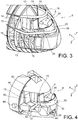
figure 3 représente une vue en perspective similaire à celle de lafigure 2 , avec les peaux de fuselage retirées pour une meilleure lisibilité de la figure ; - la
figure 4 représente une vue en perspective similaire à celle de lafigure 3 , avec l'ossature de cockpit retirée pour une lisibilité encore améliorée ; - la
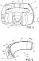
figure 5 représente une vue de face de celle montrée sur lafigure 4 ; - la
figure 6 représente une vue en perspective d'un module selon l'invention, équipant le cockpit de la pointe avant montrée sur les figures précédentes ; - la
figure 7 représente une vue en perspective du module similaire à la précédente, selon un autre angle de vue ; - la
figure 8 est une vue de face de celles montrées sur lesfigures 6 et7 ; - la
figure 9 est une vue en perspective du module montré sur lafigure 7 , coupé par un plan P1 de celle-ci ; - la
figure 10 est une vue en coupe du module coupé selon le plan P2 de lafigure 9 ; - la
figure 11 représente une vue partielle agrandie de celle de lafigure 3 ; - la
figure 12 représente une vue similaire à la précédente, montrant également des diffuseurs d'air ; - la
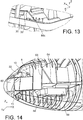
figure 13 représente une vue en perspective similaire à la précédente, selon un autre angle de vue ; et - la
figure 14 représente une vue en perspective similaire à celle de lafigure 3 , selon un autre angle de vue. - En référence à la
figure 1 , il est représenté un aéronef 100 du type avion commercial, comprenant deux ailes 2 (une seule visible sur lafigure 1 ) fixées à un fuselage 3 et portant chacune une turbomachine 1 du type à double flux, tel qu'un turboréacteur. - Sur cet aéronef 100, il est prévu une pointe avant 6 qui est spécifique à la présente invention, et dont un mode de réalisation préféré va à présent être décrit en référence aux figures suivantes.
- Dans toute la description qui va suivre, par convention, la direction X correspond à la direction longitudinale de l'aéronef, cette direction correspondant également à la direction longitudinale de la pointe avant 6, ainsi qu'à celle du cockpit 8 défini par cette pointe. D'autre part, la direction Y correspond à la direction latérale ou transversale de l'aéronef, cette direction correspondant également à la direction latérale de la pointe avant 6, ainsi qu'à celle du cockpit 8. Enfin, la direction Z correspond à la direction verticale ou de la hauteur, ces trois directions X, Y, Z étant orthogonales entre elles. En outre, les termes « avant » et « arrière » sont à considérer en rapport à une direction d'avancement de l'aéronef, suite à la poussée des turbomachines.
- Sur les
figures 2 à 5 , il est représenté de manière plus détaillée la pointe avant 6 de l'aéronef, et notamment son cockpit 8 qui présente ici la particularité de disposer d'un volume plutôt réduit par rapport aux solutions conventionnelles. En particulier, il prévoit un siège pilote 10 centré au sein du cockpit selon la direction Y pour accueillir le pilote, ainsi qu'un siège copilote 12 décalé du siège pilote 10 vers l'arrière selon la direction X et vers la droite selon la direction Y. La réduction du volume du cockpit est motivée par des raisons économiques, à savoir par le souhait d'augmenter le volume de la cabine passager. - Le cockpit 8 est délimité en partie par un plancher de cockpit 13, et par une ossature 14 visible sur la
figure 3 , qui fait partie intégrante du fuselage de la pointe avant 6. Cette ossature 14 comprend des cadres transversaux 15, certains interrompus par une zone de pare-brise comportant une armature structurale de pare-brise. Cette armature est formée par deux cadres inférieur et supérieur 16, agencés sensiblement dans des plans XY et suivant le profil de la pointe avant en forme générale d'ogive. Elle comprend également des cadres latéraux 18 reliant les deux cadres 16, et s'étendant au-delà de ces derniers. À l'arrière, cette armature est complétée par l'un des cadres transversaux 15. Préférentiellement, l'armature structurale de pare-brise 16, 18 est configurée pour recevoir seulement trois vitres montrées sur lafigure 2 , à savoir une vitre avant de pare-brise 20a centrée selon la direction Y, et deux vitres latérales 20b agencées de part et d'autre de la vitre 20a selon cette même direction. - L'une des particularités de l'invention réside dans l'implantation d'un module innovant au sein du cockpit. Ce module, référencé 22 sur les figures, est prévu pour intégrer plusieurs fonctions tout en formant un même et unique ensemble monté à l'aide de moyens conventionnels sur l'ossature 14 du cockpit. Plus précisément, le module 22 est préférentiellement fixé sur le cadre inférieur 16 de l'armature structurale de pare-brise, par exemple en trois ou quatre points de fixation seulement, répartis le long de ce cadre 16. L'étape de fixation du module 22 sur l'armature structurale de pare-brise s'avère ainsi particulièrement simple à mettre en oeuvre, avec pour conséquence une réduction du temps d'assemblage du cockpit, et une amélioration de cadences de production des aéronefs.
- Principalement, le module 22 comprend un tableau de bord 24, un bloc de distribution d'air de climatisation 26, ainsi qu'un capot 30 d'isolation thermique du bloc 26. Il peut comprendre d'autres éléments, comme un ou plusieurs écrans destinés à être supportés en face avant sur le tableau de bord, ce/ces écrans (non représentés sur les
figures 2 à 5 ) étant préférentiellement des écrans à diodes électroluminescentes organiques, dits écrans OLED. Ces écrans sont de faible épaisseur, et ne diffusent pas ou que très peu de chaleur. Il n'est donc pas nécessaire de prévoir une extraction d'air chaud. Leur encombrement est également réduit, tout comme leur besoin en câbles électriques, ce qui participe à la compacité du module ainsi qu'à sa capacité à intégrer d'autres éléments tout en conservant un encombrement global raisonnable. - Alternativement, le/les écrans peuvent être rapportés ultérieurement sur le tableau de bord, après la fixation du module sur l'armature structurale de pare-brise, sans sortir du cadre de l'invention.
- Parmi les autres composants susceptibles d'être intégrés au module 22, il est noté par exemple des diffuseurs d'air ou des vannes de régulation de débit d'air, comme cela va être décrit ultérieurement.
- En référence à présent aux
figures 6 à 10 , il est montré le module 22 de manière plus détaillée. Le tableau de bord 24 et le bloc de distribution d'air 26 peuvent être réalisés séparément, et fixés l'un sur l'autre avant le montage du module dans le cockpit. Dans ce cas, le tableau de bord 24 prend de préférence la forme d'un panneau sandwich. La fixation des deux éléments 24, 26 l'un sur l'autre s'effectue par exemple à l'aide d'agrafes. Alternativement, ces deux éléments 24, 26 sont réalisés d'une seule pièce, c'est-à-dire monobloc. Par exemple, la réalisation de cette pièce unique s'effectue par injection de résine basse pression, ou encore par impression 3D. Le capot d'isolation thermique 30 est préférentiellement rapporté sur cet ensemble monobloc, ou bien réalisé d'une seule pièce avec ce dernier. - Dans tous les cas, le bloc 26 est solidaire d'une face arrière 32 du tableau de bord 24, et longe ce même tableau recevant au moins un écran OLED 31 schématisé sur la
figure 6 . Le tableau 24 adopte une forme générale de secteur angulaire de tronc de cône, en étant destinée à être centrée dans le cockpit selon la direction Y. De par la forme tronconique de ce tableau 24, celui-ci présente une courbure autour de la direction Z. Néanmoins, une double courbure pourrait être prévue au sein du tableau de bord 24, sans sortir du cadre de l'invention. - Le bloc de distribution d'air 26 présente une forme générale identique ou similaire à celle du tableau qu'il longe sur une grande partie de la longueur de ce dernier, voire sur sensiblement la même longueur. Le bloc 26, adoptant donc lui aussi une forme générale de secteur angulaire de tronc de cône, présente une section sensiblement constante et rectangulaire. Dans le cas préféré d'une réalisation monobloc, le grand côté arrière de ce rectangle est ainsi confondu avec la face arrière 32 du tableau de bord 24, comme cela est le mieux visible sur la
figure 9 . L'épaisseur du bloc 26 est supérieure à celle du tableau de bord 24, mais suffisamment faible pour que ce bloc puisse être enfermé dans un espace 34 agencé entre le tableau 24 et le capot d'isolation thermique 30. Cet enfermement est total ou partiel. Dans le mode de réalisation préféré décrit et représenté, seules deux extrémités latérales supérieures opposées du bloc 26 sont agencées en dehors de l'espace 34. - Le capot 30 suit également la courbure des éléments 24, 26 autour de la direction Z, et présente une section en forme générale de C ouvert vers l'arrière. Les deux extrémités du C sont ainsi raccordées respectivement sur les chants inférieur et supérieur du tableau de bord 24.
- Le bloc de distribution d'air de climatisation 26 comporte tout d'abord un distributeur d'air 36, adjacent à une extrémité latérale droite 24a du tableau de bord 24. Le distributeur 36 présente une forme sensiblement parallélépipédique, s'étendant dans la direction 38 de la hauteur du tableau. Ce distributeur 36 est raccordé à une bouche d'entrée d'air 40, par exemple de section circulaire et prévue pour amener l'air frais dans le distributeur. La bouche 40 fait préférentiellement partie intégrante du module 22 avant son montage dans le cockpit, même si une intégration postérieure à ce montage est possible, sans sortir du cadre de l'invention. La bouche 40 présente une première extrémité connectée à une ouverture arrière prévue sur le distributeur 36, puis traverse l'espace 34 ainsi que le capot 30 pour déboucher sur une seconde extrémité agencée à l'extérieur du module. Cette seconde extrémité de la bouche d'entrée d'air 40 est connectée à un conduit d'amenée d'air 42 visible sur la
figure 4 , lui-même alimenté en air de manière classique par un équipement 44 connu en soi. Ce conduit 42 alimente par ailleurs en air un autre conduit 46 s'étendant vers le haut le long de l'ossature du cockpit 8. Cet autre conduit porte des bouches de sortie ou des diffuseurs 48, 50, destinées à diriger de l'air de climatisation en direction du siège 12 pour rafraîchir le copilote, et à introduire de l'air depuis une zone supérieure du cockpit afin de générer une climatisation dite « d'ambiance ». - Le raccordement du conduit d'amenée d'air 42, sur la seconde extrémité de la bouche d'entrée d'air 40 du module 22, s'effectue préférentiellement après le montage de ce dernier dans le cockpit. En d'autres termes, ce conduit d'amenée d'air 42 n'est de préférence pas intégré au module 22, mais raccordé à ce dernier dans le cockpit.
- De manière analogue, le bloc de distribution d'air de climatisation 26 comporte également un collecteur d'excédent d'air 56, adjacent à une extrémité latérale gauche 24b du tableau de bord 24. Le collecteur 56 présente une forme sensiblement parallélépipédique, s'étendant dans la direction 38 de la hauteur du tableau. Ce collecteur 56 est raccordé à une bouche de sortie d'excédent d'air 60, par exemple de section circulaire et prévue pour extraire l'air frais non-utilisé en dehors du collecteur 56.
- La bouche 60 fait préférentiellement partie intégrante du module 22 avant son montage dans le cockpit, même si une intégration postérieure à ce montage est possible, sans sortir du cadre de l'invention. La bouche 60 présente une première extrémité connectée à une ouverture arrière prévue sur le collecteur 56, puis traverse l'espace 34 ainsi que le capot 30 pour déboucher sur une seconde extrémité agencée à l'extérieur du module.
- Cette seconde extrémité de la bouche d'excédent d'air 60 est soit libre, soit raccordé à un conduit d'évacuation (non représenté). Dans les deux cas, il est préférentiellement fait en sorte que cet excédent d'air soit introduit dans un compartiment inférieur avant de la pointe avant, ce compartiment étant référencé 62 sur la
figure 14 . Il s'agit d'un compartiment 62 situé sous le plancher de cockpit 13 et sous un plancher de cabine passager 64, qui loge des armoires électriques 66 placées en arrière par rapport à une paroi arrière de cockpit 68. À titre indicatif, il est noté que dans certaines solutions antérieures, ce compartiment 62 présente un volume plus grand permettant une implantation des armoires 66 et d'autres équipements plus en avant au sein de ce compartiment. Le rétrécissement de cette pointe avant conduit donc à décaler certains équipements vers l'arrière dans le compartiment 62, ou à envisager leur déplacement dans d'autres parties de l'aéronef. Par conséquent, en intégrant le bloc 26 dans le module de cockpit 22, l'invention apporte une solution satisfaisante à la problématique de logement des systèmes de distribution d'air de climatisation de l'art antérieur, dont une grande partie des composants était agencée dans le compartiment 62 de volume supérieur, sous le plancher de cockpit. - De retour aux
figures 6 à 10 , le bloc de distribution d'air de climatisation 26 comporte une pluralité de canaux de distribution d'air 70, prévus dans un nombre compris par exemple entre quatre et dix. Ces canaux 70, de section sensiblement carrée ou rectangulaire, sont empilés les uns sur les autres selon la direction 38 de la hauteur du tableau de bord 24, dont ils longent la face arrière 32. D'ailleurs, chaque canal 70 s'inscrit dans un plan XY en présentant une courbure sensiblement identique, localement, à la courbure du tableau de bord 24 autour de la direction Z. Cet agencement permet le raidissement du tableau 24 par les canaux 70, le distributeur 36 et le collecteur 56, de même que le bloc 26 se trouve lui-même renforcé par le tableau adjacent 24. Cela conduit à une masse et à un encombrement global optimisés pour le module 22, avec pour conséquence une plus grande facilité de montage contribuant à améliorer encore davantage les cadences de production. - Dans le cas préféré d'une réalisation monobloc, le côté arrière de chaque canal de distribution d'air 70 est confondu avec la face arrière 32 du tableau de bord 24, comme cela est le mieux visible sur la
figure 9 . - Les canaux 70 s'étendent en longueur entre le distributeur 34 et le collecteur 56, en comportant chacun une première extrémité 70a communiquant avec le distributeur d'air 36, ainsi qu'une seconde extrémité 70b communiquant avec le collecteur d'excédent d'air 56. De plus, chaque canal 70 est équipé d'une sortie d'air 72 agencée entre ses première et seconde extrémités 70a, 70b. Comme cela est parfaitement visible sur la
figure 8 , les sorties 72 des différents canaux 70 sont espacées les unes des autres dans la direction de la longueur de bloc 26 allant de son distributeur 36 vers son collecteur 56. - L'une des sorties 72 va à présent être décrite plus spécifiquement en référence aux
figures 9 et 10 . Cette sortie 72 prend par exemple la forme d'une simple ouverture à travers la paroi avant du canal 70 concerné. Elle peut être équipée d'une vanne de régulation de débit d'air 74, comportant une excroissance 76 vers l'avant faisant partie intégrante du bloc 26. La vanne 74 comprend également un déflecteur 78 piloté en rotation par une tige de commande 80, elle-même commandée par un moteur 82. En fonction de la position angulaire du déflecteur 78 (deux positions schématisées sur lafigure 10 ), le débit d'air s'échappant par la sortie 72 varie. Dans une position intermédiaire du déflecteur 78 (non représentée), une partie du débit d'air circulant en amont dans le canal 70 est dirigée vers la sortie 72, tandis que l'autre partie du débit poursuit son chemin dans le canal 70 jusqu'au collecteur d'excédent d'air 56. - La sortie 72 est aussi de préférence connectée à un raccord 84, souple ou rigide, dont l'une des extrémités est préférentiellement raccordée sur l'excroissance 76 de la vanne 74 équipant la sortie, et dont l'autre extrémité peut être équipée d'un diffuseur d'air 86 et/ou d'un réchauffeur d'air 88 pour ajuster la température à la consigne souhaitée. Pour certains cas au moins, le diffuseur 86 équipant l'extrémité du raccord 84 peut être porté par le capot 30, comme cela a été schématisé dans la
figure 10 . - Ainsi, les vannes 74, les diffuseurs 86 ainsi que les réchauffeurs 88 sont intégrés au module 22 avant son montage dans le cockpit. Pourfaciliter la maintenance des moteurs 82 des vannes 74, ces moteurs sont également portés par le capot 30, au niveau d'une portion supérieure 30' de ce capot comme cela est visible sur la
figure 11 . Ils sont de ce fait aisément accessibles aux opérateurs, et les démontages/montages de ces moteurs 82 peuvent par exemple être effectués par un simple mouvement de quart de tour, grâce à une liaison à baïonnette ou équivalente entre chaque moteur 82 déporté vers le haut, et la portion supérieure 30' du capot. - En référence plus spécifiquement, il va être décrit un exemple de réalisation avec sept canaux 70 empilés, chacun présentant une fonction différente. Ces fonctions vont à présent être décrites, en partant du canal le plus haut vers le canal le plus bas dans l'empilement.
- Le premier canal 70 comporte deux sorties 72, respectivement agencées aux extrémités de celui-ci. Ces deux sorties 72 sont chacune équipée d'un raccord 84 orientant l'air en direction du tronc supérieur et/ou de la tête du pilote. Elles peuvent être équipées d'un réchauffeur 88 et/ou d'un diffuseur, comme cela a été montré sur la
figure 10 . Il est noté que pour ce premier canal, les raccords 84 sont agencés entièrement à l'extérieur de l'espace 34, puisque leurs sorties associées 82 ne sont préférentiellement par recouvertes par le capot d'isolation thermique 30. - Le second canal 70 comporte une sortie 82 équipée d'un raccord 84 à l'extrémité duquel se trouve un diffuseur 86a, représenté sur la
figure 12 . Ce diffuseur 86a, de préférence intégré au module 22 avant son montage dans le cockpit, est situé sur la portion supérieure 30' du capot 30. L'air qui s'extrait de ce diffuseur 86a est dédié au désembuage de la partie gauche de la vitre avant de pare-brise. - De manière analogue, le troisième canal 70 comporte une sortie 82 équipée d'un raccord 84 à l'extrémité duquel se trouve un diffuseur 86b, représenté sur la
figure 12 . Ce diffuseur 86b, de préférence aussi intégré au module 22 avant son montage dans le cockpit, est situé sur la portion supérieure 30' du capot 30. L'air qui s'extrait de ce diffuseur 86b est dédié au désembuage de la partie droite de la vitre avant de pare-brise. - Le quatrième canal 70 comporte une sortie 82 équipée d'un raccord 84 traversant une extrémité latérale du module 22, et à l'extrémité duquel se trouve un diffuseur 86c, représenté sur la
figure 13 . Ce diffuseur 86c, de préférence rapporté après le montage du module 22 dans le cockpit, est situé à gauche de ce module, en étant fixé sur l'ossature de cockpit. L'air qui s'extrait de ce diffuseur 86c est dédié au désembuage de la vitre latérale gauche de pare-brise. - Le cinquième canal 70 comporte la sortie 72 déjà décrite en référence aux
figures 9 et 10 . L'air qui s'extrait du diffuseur 86 est dédié à la ventilation en direction du pied gauche du pilote. De manière analogue, l'air qui s'extrait du diffuseur associé à la sortie 72 du sixième canal 70 est dédié à la ventilation en direction du pied droit du pilote. - Enfin, le septième et dernier canal 70 comporte une sortie 82 équipée d'un raccord 84 traversant l'autre extrémité latérale du module 22. Un diffuseur 86d, représenté sur la
figure 12 , se trouve à l'extrémité de ce raccord. Ce diffuseur 86d, de préférence rapporté après le montage du module 22 dans le cockpit, est situé à droite de ce module, en étant fixé sur l'ossature de cockpit. L'air qui s'extrait de ce diffuseur 86d est dédié au désembuage de la vitre latérale droite de pare-brise. - Bien entendu, diverses modifications peuvent être apportées par l'homme du métier à l'invention qui vient d'être décrite, uniquement à titre d'exemples non limitatifs, et dont la portée est définie par les revendications jointes en annexe.
Claims (16)
- Module (22) pour cockpit (8) d'aéronef, le module comprenant un tableau de bord (24) destiné à supporter au moins un écran (31), caractérisé en ce qu'il comprend de plus un bloc de distribution d'air de climatisation (26) longeant ce tableau de bord et solidaire d'une face arrière (32) de ce dernier, le bloc de distribution d'air de climatisation (26) comprenant :- un distributeur d'air (36) ;- un collecteur d'excédent d'air (56) ;- une pluralité de canaux de distribution d'air (70) comportant chacun une première extrémité (70a) communiquant avec le distributeur d'air (36) ainsi qu'une seconde extrémité (70b) communiquant avec le collecteur d'excédent d'air (56), chaque canal de distribution (70) étant équipé d'une sortie d'air (72) agencée entre ses première et seconde extrémités (70a, 70b).
- Module selon la revendication 1, caractérisé en ce que la sortie d'air (72) d'au moins l'un des canaux de distribution d'air (70) est équipée d'une vanne de régulation de débit d'air (74).
- Module selon la revendication 1 ou la revendication 2, caractérisé en ce que la sortie d'air (72) d'au moins l'un des canaux de distribution d'air (70) est connectée à un raccord (84), ce dernier étant préférentiellement équipé d'un diffuseur d'air (86) et/ou d'un réchauffeur d'air (88).
- Module selon l'une quelconque des revendications précédentes, caractérisé en ce que le bloc de distribution d'air de climatisation (26) est configuré pour assurer au moins l'une des fonctions suivantes, et préférentiellement une pluralité d'entre elles :- ventilation en direction d'un ou des deux pieds du pilote ;- ventilation en direction du tronc supérieur et/ou de la tête du pilote ;- désembuage d'une vitre avant (20a) de pare-brise ;- désembuage d'une ou plusieurs vitres latérales (20b) de pare-brise.
- Module selon l'une quelconque des revendications précédentes, caractérisé en ce que le distributeur d'air (36) du bloc (26) ainsi que le collecteur d'excédent air (56) sont adjacents à deux extrémités latérales (24a, 24b) du tableau de bord (24).
- Module selon l'une quelconque des revendications précédentes, caractérisé en ce que les canaux de distribution d'air (70) sont empilés les uns sur les autres selon une direction (38) de la hauteur du tableau de bord, et agencés entre le distributeur d'air (36) et collecteur d'excédent air (56).
- Module selon l'une quelconque des revendications précédentes, caractérisé en ce que chaque canal de distribution d'air (70) présente une courbure sensiblement identique localement à une courbure du tableau de bord (24).
- Module selon l'une quelconque des revendications précédentes, caractérisé en ce qu'il comporte un capot (30) d'isolation thermique du bloc de distribution d'air (26), ce dernier étant enfermé entre le tableau de bord (24) et le capot d'isolation thermique (30).
- Module selon la revendication 8 combinée à la revendication 3, caractérisé en ce que le capot d'isolation thermique (30) porte au moins un diffuseur d'air (86) associé à au moins l'un des canaux de distribution d'air (70).
- Module selon la revendication 8 ou la revendication 9, combinée à la revendication 2, caractérisé en ce que le capot d'isolation thermique (30) porte au moins un moteur (82) d'actionnement d'au moins une vanne de régulation de débit d'air (74) associée à au moins l'un des canaux de distribution d'air (70), chaque moteur étant préférentiellement porté au niveau d'une portion supérieure (30') du capot d'isolation thermique (30).
- Module selon l'une quelconque des revendications précédentes, caractérisé en ce qu'il comporte une bouche d'entrée d'air (40) raccordée au distributeur d'air, ainsi qu'une bouche de sortie d'excédent d'air (60) raccordée au collecteur d'excédent d'air (56).
- Module selon l'une quelconque des revendications précédentes, caractérisé en ce que le tableau de bord (24) et le bloc de distribution d'air (26) sont réalisés d'une seule pièce.
- Cockpit (8) d'aéronef comprenant une ossature (14) ainsi qu'un module (22) selon l'une quelconque des revendications précédentes, fixé sur l'ossature de cockpit, de préférence sur une armature structurale de pare-brise (15, 16, 18).
- Aéronef (100) comprenant un cockpit (8) selon la revendication 13.
- Aéronef selon la revendication 14, caractérisé en ce qu'il comprend un compartiment inférieur avant (62) situé sous un plancher de cockpit (13) et sous un plancher de cabine passager (64), le compartiment inférieur avant (62) logeant des armoires électriques (66) agencées en arrière par rapport à une paroi arrière de cockpit (68), et en ce qu'il est configuré de sorte que l'air s'échappant du collecteur d'excédent d'air (56) du module de cockpit (22) soit introduit dans le compartiment inférieur avant (62).
- Procédé d'assemblage d'un cockpit (8) selon la revendication 13, comprenant une étape de fixation du module (22) sur l'ossature de cockpit (14).
Applications Claiming Priority (1)
| Application Number | Priority Date | Filing Date | Title |
|---|---|---|---|
| FR1857365A FR3084878A1 (fr) | 2018-08-07 | 2018-08-07 | Module optimise pour cockpit d'aeronef |
Publications (2)
| Publication Number | Publication Date |
|---|---|
| EP3608229A1 true EP3608229A1 (fr) | 2020-02-12 |
| EP3608229B1 EP3608229B1 (fr) | 2021-04-14 |
Family
ID=63896387
Family Applications (1)
| Application Number | Title | Priority Date | Filing Date |
|---|---|---|---|
| EP19185632.7A Active EP3608229B1 (fr) | 2018-08-07 | 2019-07-11 | Module optimise pour cockpit d'aeronef |
Country Status (4)
| Country | Link |
|---|---|
| US (1) | US11407515B2 (fr) |
| EP (1) | EP3608229B1 (fr) |
| CN (1) | CN110816850A (fr) |
| FR (1) | FR3084878A1 (fr) |
Families Citing this family (5)
| Publication number | Priority date | Publication date | Assignee | Title |
|---|---|---|---|---|
| FR3084878A1 (fr) * | 2018-08-07 | 2020-02-14 | Airbus Operations | Module optimise pour cockpit d'aeronef |
| CN112173125B (zh) * | 2020-09-18 | 2022-10-28 | 中国特种飞行器研究所 | 一种载人飞艇座舱通风加温装置及方法 |
| KR102407402B1 (ko) * | 2020-11-19 | 2022-06-10 | 주식회사 바로텍시너지 | 고강도 경량 콕핏이 적용된 체험형 항공기 시뮬레이터 |
| CN115817832A (zh) * | 2022-12-08 | 2023-03-21 | 芜湖中科飞机制造有限公司 | 一种集成有风挡出风口的通航飞机驾驶舱仪表板遮光罩 |
| CN119408691B (zh) * | 2024-10-16 | 2025-12-30 | 中国直升机设计研究所 | 一种可变构型的串列式直升机驾驶舱 |
Citations (4)
| Publication number | Priority date | Publication date | Assignee | Title |
|---|---|---|---|---|
| EP1323555A1 (fr) * | 2001-12-27 | 2003-07-02 | Renault s.a.s. | Dispositif et procédé de climatisation de l'habitacle d'un véhicle automobile |
| US20050046164A1 (en) * | 2003-08-27 | 2005-03-03 | Paul Arnold | Lost core structural instrument panel |
| US20140209740A1 (en) * | 2011-09-30 | 2014-07-31 | Airbus Operations Sas | Aircraft cockpit, in particular the front portion of an aircraft cockpit |
| US20160244171A1 (en) * | 2015-02-25 | 2016-08-25 | Mitsubishi Aircraft Corporation | Aircraft |
Family Cites Families (6)
| Publication number | Priority date | Publication date | Assignee | Title |
|---|---|---|---|---|
| JP4135253B2 (ja) * | 1998-05-13 | 2008-08-20 | 株式会社デンソー | 車両用空調装置 |
| JP4281179B2 (ja) * | 1998-11-25 | 2009-06-17 | 株式会社デンソー | 車両用空調装置 |
| PL2979975T3 (pl) * | 2014-07-30 | 2018-01-31 | Airbus Helicopters Deutschland GmbH | Statek powietrzny ze strukturą ramową, która zawiera co najmniej jedną pustą ramę |
| EP3138774A1 (fr) * | 2015-09-04 | 2017-03-08 | Airbus Operations GmbH | Système de conditionnement d'air pour aéronef avec une réduction de la demande en air du processus |
| DE102016102800A1 (de) * | 2016-02-17 | 2017-08-17 | Airbus Operations Gmbh | Flugzeug mit einem Klimatisierungssystem und ein Verfahren zur Klimatisierung eines Flugzeugs |
| FR3084878A1 (fr) * | 2018-08-07 | 2020-02-14 | Airbus Operations | Module optimise pour cockpit d'aeronef |
-
2018
- 2018-08-07 FR FR1857365A patent/FR3084878A1/fr not_active Withdrawn
-
2019
- 2019-07-11 EP EP19185632.7A patent/EP3608229B1/fr active Active
- 2019-07-29 US US16/524,689 patent/US11407515B2/en active Active
- 2019-08-07 CN CN201910723756.1A patent/CN110816850A/zh active Pending
Patent Citations (4)
| Publication number | Priority date | Publication date | Assignee | Title |
|---|---|---|---|---|
| EP1323555A1 (fr) * | 2001-12-27 | 2003-07-02 | Renault s.a.s. | Dispositif et procédé de climatisation de l'habitacle d'un véhicle automobile |
| US20050046164A1 (en) * | 2003-08-27 | 2005-03-03 | Paul Arnold | Lost core structural instrument panel |
| US20140209740A1 (en) * | 2011-09-30 | 2014-07-31 | Airbus Operations Sas | Aircraft cockpit, in particular the front portion of an aircraft cockpit |
| US20160244171A1 (en) * | 2015-02-25 | 2016-08-25 | Mitsubishi Aircraft Corporation | Aircraft |
Also Published As
| Publication number | Publication date |
|---|---|
| US20200055606A1 (en) | 2020-02-20 |
| CN110816850A (zh) | 2020-02-21 |
| EP3608229B1 (fr) | 2021-04-14 |
| FR3084878A1 (fr) | 2020-02-14 |
| US11407515B2 (en) | 2022-08-09 |
Similar Documents
| Publication | Publication Date | Title |
|---|---|---|
| EP3608229B1 (fr) | Module optimise pour cockpit d'aeronef | |
| EP3612445B1 (fr) | Ensemble pour aeronef comprenant une structure primaire de mat d'accrochage fixee a un caisson de voilure a l'aide d'une liaison boulonnee | |
| EP3319824B1 (fr) | Dispositif de chauffage, ventilation et/ou climatisation pour vehicule automobile, module additionnel et procede d'assemblage correspondants | |
| EP1601543B2 (fr) | Dispositif de chauffage-ventilation et/ou climatisation de structure compacte pour l'habitacle d'un vehicule automobile | |
| WO2009112669A1 (fr) | Structure d'accrochage pour turboréacteur | |
| EP2487111B1 (fr) | Dispositif de ventilation d'un compartiment de moteur d'aéronef | |
| EP3509881B1 (fr) | Agencement d'un dispositif de ventilation dans un encadrement structurel de toit et véhicule comportant un tel agencement | |
| FR3053658A1 (fr) | Module de cockpit d'aeronef, aeronef comportant un tel module et procede d'installation du module dans un cockpit | |
| FR2742383A1 (fr) | Dispositif de chauffage et/ou climatisation de l'habitacle d'un vehicule automobile | |
| EP3898308B1 (fr) | Planche de bord modulable | |
| US6848652B2 (en) | Aircraft heater | |
| FR2724900A1 (fr) | Planche de bord pour vehicule automobile | |
| EP0704329B1 (fr) | Dispositif de chauffage et/ou climatisation de véhicule automobile | |
| EP3428058B1 (fr) | Fuselage et aeronef comportant une sous-structure multifonctionnelle de distribution d'air et procede d'assemblage | |
| EP3592595A1 (fr) | Unite de refroidissement pour face avant de vehicule automobile | |
| EP4489983B1 (fr) | Planche de bord comprenant une veine de ventilation | |
| EP3268239B1 (fr) | Circuits de climatisation pour vehicule automobile | |
| FR2790719A1 (fr) | Procede pour assembler un bloc de chauffage et/ou climatisation et une planche de bord, et ensemble | |
| EP3887180A1 (fr) | Véhicule automobile comprenant une installation de chauffage,ventilation et climatisation d'air fixée dans le compartiment moteur | |
| EP1405743B1 (fr) | Dispositif de chauffage et/ou climatisation de l'habitacle d'un véhicule automobile, à perte de charge réduite | |
| EP1323555A1 (fr) | Dispositif et procédé de climatisation de l'habitacle d'un véhicle automobile | |
| FR3144582A1 (fr) | Ensemble supérieur de siège comportant un dossier et un appui-tête, et siège comportant un tel ensemble | |
| FR3153331A1 (fr) | Portion d'aéronef à distribution modulable de fluide et procédé d'aménagement associé | |
| FR3149550A1 (fr) | Grille de protection avec support de caméra pour véhicule automobile et procédé de fabrication | |
| EP3194195A1 (fr) | Ensemble de refroidissement pour un organe fonctionnel a refroidir comprenant un radiateur et un support de motoventilateur |
Legal Events
| Date | Code | Title | Description |
|---|---|---|---|
| STAA | Information on the status of an ep patent application or granted ep patent |
Free format text: STATUS: EXAMINATION IS IN PROGRESS |
|
| PUAI | Public reference made under article 153(3) epc to a published international application that has entered the european phase |
Free format text: ORIGINAL CODE: 0009012 |
|
| 17P | Request for examination filed |
Effective date: 20190711 |
|
| AK | Designated contracting states |
Kind code of ref document: A1 Designated state(s): AL AT BE BG CH CY CZ DE DK EE ES FI FR GB GR HR HU IE IS IT LI LT LU LV MC MK MT NL NO PL PT RO RS SE SI SK SM TR |
|
| AX | Request for extension of the european patent |
Extension state: BA ME |
|
| RBV | Designated contracting states (corrected) |
Designated state(s): AL AT BE BG CH CY CZ DE DK EE ES FI FR GB GR HR HU IE IS IT LI LT LU LV MC MK MT NL NO PL PT RO RS SE SI SK SM TR |
|
| GRAP | Despatch of communication of intention to grant a patent |
Free format text: ORIGINAL CODE: EPIDOSNIGR1 |
|
| STAA | Information on the status of an ep patent application or granted ep patent |
Free format text: STATUS: GRANT OF PATENT IS INTENDED |
|
| INTG | Intention to grant announced |
Effective date: 20201223 |
|
| GRAS | Grant fee paid |
Free format text: ORIGINAL CODE: EPIDOSNIGR3 |
|
| GRAA | (expected) grant |
Free format text: ORIGINAL CODE: 0009210 |
|
| STAA | Information on the status of an ep patent application or granted ep patent |
Free format text: STATUS: THE PATENT HAS BEEN GRANTED |
|
| AK | Designated contracting states |
Kind code of ref document: B1 Designated state(s): AL AT BE BG CH CY CZ DE DK EE ES FI FR GB GR HR HU IE IS IT LI LT LU LV MC MK MT NL NO PL PT RO RS SE SI SK SM TR |
|
| REG | Reference to a national code |
Ref country code: GB Ref legal event code: FG4D Free format text: NOT ENGLISH |
|
| REG | Reference to a national code |
Ref country code: CH Ref legal event code: EP |
|
| REG | Reference to a national code |
Ref country code: DE Ref legal event code: R096 Ref document number: 602019003866 Country of ref document: DE |
|
| REG | Reference to a national code |
Ref country code: IE Ref legal event code: FG4D Free format text: LANGUAGE OF EP DOCUMENT: FRENCH |
|
| REG | Reference to a national code |
Ref country code: AT Ref legal event code: REF Ref document number: 1382159 Country of ref document: AT Kind code of ref document: T Effective date: 20210515 |
|
| REG | Reference to a national code |
Ref country code: LT Ref legal event code: MG9D |
|
| REG | Reference to a national code |
Ref country code: AT Ref legal event code: MK05 Ref document number: 1382159 Country of ref document: AT Kind code of ref document: T Effective date: 20210414 |
|
| REG | Reference to a national code |
Ref country code: NL Ref legal event code: MP Effective date: 20210414 |
|
| PG25 | Lapsed in a contracting state [announced via postgrant information from national office to epo] |
Ref country code: FI Free format text: LAPSE BECAUSE OF FAILURE TO SUBMIT A TRANSLATION OF THE DESCRIPTION OR TO PAY THE FEE WITHIN THE PRESCRIBED TIME-LIMIT Effective date: 20210414 Ref country code: LT Free format text: LAPSE BECAUSE OF FAILURE TO SUBMIT A TRANSLATION OF THE DESCRIPTION OR TO PAY THE FEE WITHIN THE PRESCRIBED TIME-LIMIT Effective date: 20210414 Ref country code: HR Free format text: LAPSE BECAUSE OF FAILURE TO SUBMIT A TRANSLATION OF THE DESCRIPTION OR TO PAY THE FEE WITHIN THE PRESCRIBED TIME-LIMIT Effective date: 20210414 Ref country code: NL Free format text: LAPSE BECAUSE OF FAILURE TO SUBMIT A TRANSLATION OF THE DESCRIPTION OR TO PAY THE FEE WITHIN THE PRESCRIBED TIME-LIMIT Effective date: 20210414 Ref country code: BG Free format text: LAPSE BECAUSE OF FAILURE TO SUBMIT A TRANSLATION OF THE DESCRIPTION OR TO PAY THE FEE WITHIN THE PRESCRIBED TIME-LIMIT Effective date: 20210714 Ref country code: AT Free format text: LAPSE BECAUSE OF FAILURE TO SUBMIT A TRANSLATION OF THE DESCRIPTION OR TO PAY THE FEE WITHIN THE PRESCRIBED TIME-LIMIT Effective date: 20210414 |
|
| PG25 | Lapsed in a contracting state [announced via postgrant information from national office to epo] |
Ref country code: LV Free format text: LAPSE BECAUSE OF FAILURE TO SUBMIT A TRANSLATION OF THE DESCRIPTION OR TO PAY THE FEE WITHIN THE PRESCRIBED TIME-LIMIT Effective date: 20210414 Ref country code: NO Free format text: LAPSE BECAUSE OF FAILURE TO SUBMIT A TRANSLATION OF THE DESCRIPTION OR TO PAY THE FEE WITHIN THE PRESCRIBED TIME-LIMIT Effective date: 20210714 Ref country code: PL Free format text: LAPSE BECAUSE OF FAILURE TO SUBMIT A TRANSLATION OF THE DESCRIPTION OR TO PAY THE FEE WITHIN THE PRESCRIBED TIME-LIMIT Effective date: 20210414 Ref country code: RS Free format text: LAPSE BECAUSE OF FAILURE TO SUBMIT A TRANSLATION OF THE DESCRIPTION OR TO PAY THE FEE WITHIN THE PRESCRIBED TIME-LIMIT Effective date: 20210414 Ref country code: PT Free format text: LAPSE BECAUSE OF FAILURE TO SUBMIT A TRANSLATION OF THE DESCRIPTION OR TO PAY THE FEE WITHIN THE PRESCRIBED TIME-LIMIT Effective date: 20210816 Ref country code: SE Free format text: LAPSE BECAUSE OF FAILURE TO SUBMIT A TRANSLATION OF THE DESCRIPTION OR TO PAY THE FEE WITHIN THE PRESCRIBED TIME-LIMIT Effective date: 20210414 Ref country code: IS Free format text: LAPSE BECAUSE OF FAILURE TO SUBMIT A TRANSLATION OF THE DESCRIPTION OR TO PAY THE FEE WITHIN THE PRESCRIBED TIME-LIMIT Effective date: 20210814 Ref country code: GR Free format text: LAPSE BECAUSE OF FAILURE TO SUBMIT A TRANSLATION OF THE DESCRIPTION OR TO PAY THE FEE WITHIN THE PRESCRIBED TIME-LIMIT Effective date: 20210715 |
|
| REG | Reference to a national code |
Ref country code: DE Ref legal event code: R097 Ref document number: 602019003866 Country of ref document: DE |
|
| PG25 | Lapsed in a contracting state [announced via postgrant information from national office to epo] |
Ref country code: DK Free format text: LAPSE BECAUSE OF FAILURE TO SUBMIT A TRANSLATION OF THE DESCRIPTION OR TO PAY THE FEE WITHIN THE PRESCRIBED TIME-LIMIT Effective date: 20210414 Ref country code: CZ Free format text: LAPSE BECAUSE OF FAILURE TO SUBMIT A TRANSLATION OF THE DESCRIPTION OR TO PAY THE FEE WITHIN THE PRESCRIBED TIME-LIMIT Effective date: 20210414 Ref country code: RO Free format text: LAPSE BECAUSE OF FAILURE TO SUBMIT A TRANSLATION OF THE DESCRIPTION OR TO PAY THE FEE WITHIN THE PRESCRIBED TIME-LIMIT Effective date: 20210414 Ref country code: SM Free format text: LAPSE BECAUSE OF FAILURE TO SUBMIT A TRANSLATION OF THE DESCRIPTION OR TO PAY THE FEE WITHIN THE PRESCRIBED TIME-LIMIT Effective date: 20210414 Ref country code: EE Free format text: LAPSE BECAUSE OF FAILURE TO SUBMIT A TRANSLATION OF THE DESCRIPTION OR TO PAY THE FEE WITHIN THE PRESCRIBED TIME-LIMIT Effective date: 20210414 Ref country code: ES Free format text: LAPSE BECAUSE OF FAILURE TO SUBMIT A TRANSLATION OF THE DESCRIPTION OR TO PAY THE FEE WITHIN THE PRESCRIBED TIME-LIMIT Effective date: 20210414 Ref country code: SK Free format text: LAPSE BECAUSE OF FAILURE TO SUBMIT A TRANSLATION OF THE DESCRIPTION OR TO PAY THE FEE WITHIN THE PRESCRIBED TIME-LIMIT Effective date: 20210414 |
|
| PLBE | No opposition filed within time limit |
Free format text: ORIGINAL CODE: 0009261 |
|
| STAA | Information on the status of an ep patent application or granted ep patent |
Free format text: STATUS: NO OPPOSITION FILED WITHIN TIME LIMIT |
|
| 26N | No opposition filed |
Effective date: 20220117 |
|
| PG25 | Lapsed in a contracting state [announced via postgrant information from national office to epo] |
Ref country code: MC Free format text: LAPSE BECAUSE OF FAILURE TO SUBMIT A TRANSLATION OF THE DESCRIPTION OR TO PAY THE FEE WITHIN THE PRESCRIBED TIME-LIMIT Effective date: 20210414 |
|
| REG | Reference to a national code |
Ref country code: BE Ref legal event code: MM Effective date: 20210731 |
|
| PG25 | Lapsed in a contracting state [announced via postgrant information from national office to epo] |
Ref country code: IS Free format text: LAPSE BECAUSE OF FAILURE TO SUBMIT A TRANSLATION OF THE DESCRIPTION OR TO PAY THE FEE WITHIN THE PRESCRIBED TIME-LIMIT Effective date: 20210814 Ref country code: LU Free format text: LAPSE BECAUSE OF NON-PAYMENT OF DUE FEES Effective date: 20210711 Ref country code: AL Free format text: LAPSE BECAUSE OF FAILURE TO SUBMIT A TRANSLATION OF THE DESCRIPTION OR TO PAY THE FEE WITHIN THE PRESCRIBED TIME-LIMIT Effective date: 20210414 |
|
| PG25 | Lapsed in a contracting state [announced via postgrant information from national office to epo] |
Ref country code: IT Free format text: LAPSE BECAUSE OF FAILURE TO SUBMIT A TRANSLATION OF THE DESCRIPTION OR TO PAY THE FEE WITHIN THE PRESCRIBED TIME-LIMIT Effective date: 20210414 Ref country code: IE Free format text: LAPSE BECAUSE OF NON-PAYMENT OF DUE FEES Effective date: 20210711 Ref country code: BE Free format text: LAPSE BECAUSE OF NON-PAYMENT OF DUE FEES Effective date: 20210731 |
|
| REG | Reference to a national code |
Ref country code: CH Ref legal event code: PL |
|
| PG25 | Lapsed in a contracting state [announced via postgrant information from national office to epo] |
Ref country code: LI Free format text: LAPSE BECAUSE OF NON-PAYMENT OF DUE FEES Effective date: 20220731 Ref country code: CH Free format text: LAPSE BECAUSE OF NON-PAYMENT OF DUE FEES Effective date: 20220731 |
|
| PG25 | Lapsed in a contracting state [announced via postgrant information from national office to epo] |
Ref country code: CY Free format text: LAPSE BECAUSE OF FAILURE TO SUBMIT A TRANSLATION OF THE DESCRIPTION OR TO PAY THE FEE WITHIN THE PRESCRIBED TIME-LIMIT Effective date: 20210414 |
|
| PG25 | Lapsed in a contracting state [announced via postgrant information from national office to epo] |
Ref country code: HU Free format text: LAPSE BECAUSE OF FAILURE TO SUBMIT A TRANSLATION OF THE DESCRIPTION OR TO PAY THE FEE WITHIN THE PRESCRIBED TIME-LIMIT; INVALID AB INITIO Effective date: 20190711 |
|
| PG25 | Lapsed in a contracting state [announced via postgrant information from national office to epo] |
Ref country code: MK Free format text: LAPSE BECAUSE OF FAILURE TO SUBMIT A TRANSLATION OF THE DESCRIPTION OR TO PAY THE FEE WITHIN THE PRESCRIBED TIME-LIMIT Effective date: 20210414 |
|
| PG25 | Lapsed in a contracting state [announced via postgrant information from national office to epo] |
Ref country code: TR Free format text: LAPSE BECAUSE OF FAILURE TO SUBMIT A TRANSLATION OF THE DESCRIPTION OR TO PAY THE FEE WITHIN THE PRESCRIBED TIME-LIMIT Effective date: 20210414 |
|
| PG25 | Lapsed in a contracting state [announced via postgrant information from national office to epo] |
Ref country code: MT Free format text: LAPSE BECAUSE OF FAILURE TO SUBMIT A TRANSLATION OF THE DESCRIPTION OR TO PAY THE FEE WITHIN THE PRESCRIBED TIME-LIMIT Effective date: 20210414 |
|
| PGFP | Annual fee paid to national office [announced via postgrant information from national office to epo] |
Ref country code: DE Payment date: 20250722 Year of fee payment: 7 |
|
| PGFP | Annual fee paid to national office [announced via postgrant information from national office to epo] |
Ref country code: GB Payment date: 20250722 Year of fee payment: 7 |
|
| PGFP | Annual fee paid to national office [announced via postgrant information from national office to epo] |
Ref country code: FR Payment date: 20250725 Year of fee payment: 7 |