EP3608155A1 - Power transmission device for vehicle - Google Patents
Power transmission device for vehicle Download PDFInfo
- Publication number
- EP3608155A1 EP3608155A1 EP19185968.5A EP19185968A EP3608155A1 EP 3608155 A1 EP3608155 A1 EP 3608155A1 EP 19185968 A EP19185968 A EP 19185968A EP 3608155 A1 EP3608155 A1 EP 3608155A1
- Authority
- EP
- European Patent Office
- Prior art keywords
- torque converter
- rotational speed
- motor
- characteristic line
- electric motor
- Prior art date
- Legal status (The legal status is an assumption and is not a legal conclusion. Google has not performed a legal analysis and makes no representation as to the accuracy of the status listed.)
- Pending
Links
- 230000005540 biological transmission Effects 0.000 title claims abstract description 67
- 230000007423 decrease Effects 0.000 description 9
- 230000000694 effects Effects 0.000 description 1
- 239000012530 fluid Substances 0.000 description 1
- 239000010720 hydraulic oil Substances 0.000 description 1
- 230000004048 modification Effects 0.000 description 1
- 238000012986 modification Methods 0.000 description 1
- 230000001360 synchronised effect Effects 0.000 description 1
Images


Classifications
-
- B—PERFORMING OPERATIONS; TRANSPORTING
- B60—VEHICLES IN GENERAL
- B60K—ARRANGEMENT OR MOUNTING OF PROPULSION UNITS OR OF TRANSMISSIONS IN VEHICLES; ARRANGEMENT OR MOUNTING OF PLURAL DIVERSE PRIME-MOVERS IN VEHICLES; AUXILIARY DRIVES FOR VEHICLES; INSTRUMENTATION OR DASHBOARDS FOR VEHICLES; ARRANGEMENTS IN CONNECTION WITH COOLING, AIR INTAKE, GAS EXHAUST OR FUEL SUPPLY OF PROPULSION UNITS IN VEHICLES
- B60K17/00—Arrangement or mounting of transmissions in vehicles
- B60K17/02—Arrangement or mounting of transmissions in vehicles characterised by arrangement, location, or kind of clutch
-
- B—PERFORMING OPERATIONS; TRANSPORTING
- B60—VEHICLES IN GENERAL
- B60L—PROPULSION OF ELECTRICALLY-PROPELLED VEHICLES; SUPPLYING ELECTRIC POWER FOR AUXILIARY EQUIPMENT OF ELECTRICALLY-PROPELLED VEHICLES; ELECTRODYNAMIC BRAKE SYSTEMS FOR VEHICLES IN GENERAL; MAGNETIC SUSPENSION OR LEVITATION FOR VEHICLES; MONITORING OPERATING VARIABLES OF ELECTRICALLY-PROPELLED VEHICLES; ELECTRIC SAFETY DEVICES FOR ELECTRICALLY-PROPELLED VEHICLES
- B60L15/00—Methods, circuits, or devices for controlling the traction-motor speed of electrically-propelled vehicles
- B60L15/20—Methods, circuits, or devices for controlling the traction-motor speed of electrically-propelled vehicles for control of the vehicle or its driving motor to achieve a desired performance, e.g. speed, torque, programmed variation of speed
-
- F—MECHANICAL ENGINEERING; LIGHTING; HEATING; WEAPONS; BLASTING
- F16—ENGINEERING ELEMENTS AND UNITS; GENERAL MEASURES FOR PRODUCING AND MAINTAINING EFFECTIVE FUNCTIONING OF MACHINES OR INSTALLATIONS; THERMAL INSULATION IN GENERAL
- F16H—GEARING
- F16H45/00—Combinations of fluid gearings for conveying rotary motion with couplings or clutches
- F16H45/02—Combinations of fluid gearings for conveying rotary motion with couplings or clutches with mechanical clutches for bridging a fluid gearing of the hydrokinetic type
-
- B—PERFORMING OPERATIONS; TRANSPORTING
- B60—VEHICLES IN GENERAL
- B60K—ARRANGEMENT OR MOUNTING OF PROPULSION UNITS OR OF TRANSMISSIONS IN VEHICLES; ARRANGEMENT OR MOUNTING OF PLURAL DIVERSE PRIME-MOVERS IN VEHICLES; AUXILIARY DRIVES FOR VEHICLES; INSTRUMENTATION OR DASHBOARDS FOR VEHICLES; ARRANGEMENTS IN CONNECTION WITH COOLING, AIR INTAKE, GAS EXHAUST OR FUEL SUPPLY OF PROPULSION UNITS IN VEHICLES
- B60K1/00—Arrangement or mounting of electrical propulsion units
-
- F—MECHANICAL ENGINEERING; LIGHTING; HEATING; WEAPONS; BLASTING
- F16—ENGINEERING ELEMENTS AND UNITS; GENERAL MEASURES FOR PRODUCING AND MAINTAINING EFFECTIVE FUNCTIONING OF MACHINES OR INSTALLATIONS; THERMAL INSULATION IN GENERAL
- F16H—GEARING
- F16H41/00—Rotary fluid gearing of the hydrokinetic type
- F16H41/24—Details
-
- B—PERFORMING OPERATIONS; TRANSPORTING
- B60—VEHICLES IN GENERAL
- B60L—PROPULSION OF ELECTRICALLY-PROPELLED VEHICLES; SUPPLYING ELECTRIC POWER FOR AUXILIARY EQUIPMENT OF ELECTRICALLY-PROPELLED VEHICLES; ELECTRODYNAMIC BRAKE SYSTEMS FOR VEHICLES IN GENERAL; MAGNETIC SUSPENSION OR LEVITATION FOR VEHICLES; MONITORING OPERATING VARIABLES OF ELECTRICALLY-PROPELLED VEHICLES; ELECTRIC SAFETY DEVICES FOR ELECTRICALLY-PROPELLED VEHICLES
- B60L2240/00—Control parameters of input or output; Target parameters
- B60L2240/40—Drive Train control parameters
- B60L2240/42—Drive Train control parameters related to electric machines
- B60L2240/423—Torque
-
- B—PERFORMING OPERATIONS; TRANSPORTING
- B60—VEHICLES IN GENERAL
- B60W—CONJOINT CONTROL OF VEHICLE SUB-UNITS OF DIFFERENT TYPE OR DIFFERENT FUNCTION; CONTROL SYSTEMS SPECIALLY ADAPTED FOR HYBRID VEHICLES; ROAD VEHICLE DRIVE CONTROL SYSTEMS FOR PURPOSES NOT RELATED TO THE CONTROL OF A PARTICULAR SUB-UNIT
- B60W2710/00—Output or target parameters relating to a particular sub-units
- B60W2710/08—Electric propulsion units
- B60W2710/083—Torque
-
- F—MECHANICAL ENGINEERING; LIGHTING; HEATING; WEAPONS; BLASTING
- F16—ENGINEERING ELEMENTS AND UNITS; GENERAL MEASURES FOR PRODUCING AND MAINTAINING EFFECTIVE FUNCTIONING OF MACHINES OR INSTALLATIONS; THERMAL INSULATION IN GENERAL
- F16H—GEARING
- F16H45/00—Combinations of fluid gearings for conveying rotary motion with couplings or clutches
- F16H2045/002—Combinations of fluid gearings for conveying rotary motion with couplings or clutches comprising a clutch between prime mover and fluid gearing
-
- F—MECHANICAL ENGINEERING; LIGHTING; HEATING; WEAPONS; BLASTING
- F16—ENGINEERING ELEMENTS AND UNITS; GENERAL MEASURES FOR PRODUCING AND MAINTAINING EFFECTIVE FUNCTIONING OF MACHINES OR INSTALLATIONS; THERMAL INSULATION IN GENERAL
- F16H—GEARING
- F16H45/00—Combinations of fluid gearings for conveying rotary motion with couplings or clutches
- F16H45/02—Combinations of fluid gearings for conveying rotary motion with couplings or clutches with mechanical clutches for bridging a fluid gearing of the hydrokinetic type
- F16H2045/021—Combinations of fluid gearings for conveying rotary motion with couplings or clutches with mechanical clutches for bridging a fluid gearing of the hydrokinetic type three chamber system, i.e. comprising a separated, closed chamber specially adapted for actuating a lock-up clutch
-
- F—MECHANICAL ENGINEERING; LIGHTING; HEATING; WEAPONS; BLASTING
- F16—ENGINEERING ELEMENTS AND UNITS; GENERAL MEASURES FOR PRODUCING AND MAINTAINING EFFECTIVE FUNCTIONING OF MACHINES OR INSTALLATIONS; THERMAL INSULATION IN GENERAL
- F16H—GEARING
- F16H47/00—Combinations of mechanical gearing with fluid clutches or fluid gearing
- F16H47/06—Combinations of mechanical gearing with fluid clutches or fluid gearing the fluid gearing being of the hydrokinetic type
-
- H—ELECTRICITY
- H02—GENERATION; CONVERSION OR DISTRIBUTION OF ELECTRIC POWER
- H02K—DYNAMO-ELECTRIC MACHINES
- H02K1/00—Details of the magnetic circuit
- H02K1/06—Details of the magnetic circuit characterised by the shape, form or construction
- H02K1/22—Rotating parts of the magnetic circuit
- H02K1/27—Rotor cores with permanent magnets
-
- Y—GENERAL TAGGING OF NEW TECHNOLOGICAL DEVELOPMENTS; GENERAL TAGGING OF CROSS-SECTIONAL TECHNOLOGIES SPANNING OVER SEVERAL SECTIONS OF THE IPC; TECHNICAL SUBJECTS COVERED BY FORMER USPC CROSS-REFERENCE ART COLLECTIONS [XRACs] AND DIGESTS
- Y02—TECHNOLOGIES OR APPLICATIONS FOR MITIGATION OR ADAPTATION AGAINST CLIMATE CHANGE
- Y02T—CLIMATE CHANGE MITIGATION TECHNOLOGIES RELATED TO TRANSPORTATION
- Y02T10/00—Road transport of goods or passengers
- Y02T10/60—Other road transportation technologies with climate change mitigation effect
- Y02T10/64—Electric machine technologies in electromobility
-
- Y—GENERAL TAGGING OF NEW TECHNOLOGICAL DEVELOPMENTS; GENERAL TAGGING OF CROSS-SECTIONAL TECHNOLOGIES SPANNING OVER SEVERAL SECTIONS OF THE IPC; TECHNICAL SUBJECTS COVERED BY FORMER USPC CROSS-REFERENCE ART COLLECTIONS [XRACs] AND DIGESTS
- Y02—TECHNOLOGIES OR APPLICATIONS FOR MITIGATION OR ADAPTATION AGAINST CLIMATE CHANGE
- Y02T—CLIMATE CHANGE MITIGATION TECHNOLOGIES RELATED TO TRANSPORTATION
- Y02T10/00—Road transport of goods or passengers
- Y02T10/60—Other road transportation technologies with climate change mitigation effect
- Y02T10/72—Electric energy management in electromobility
Definitions
- the present invention relates to a power transmission device for a vehicle.
- Conventional power transmission devices for vehicles are provided with a motor generator (electric motor) and a torque converter (see Patent Literature 1). In this configuration, drive force of the motor generator is transmitted to an output shaft via the torque converter.
- Patent Literature 1 Japanese Laid-open Patent Publication No. 2011-231857
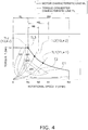
- a capacity coefficient YJ of a torque converter is set so that a characteristic line TLJ for the torque converter intersects a characteristic line ML for an electric motor in a range RL which is less than a base rotational speed, the characteristic line ML indicating a maximum output torque of a motor generator relative to each rotational speed of the motor generator, as shown in FIG. 4 .
- a maximum output torque Tm of the motor generator in the range RL can be utilized by setting the capacity coefficient YJ of the torque converter so that the characteristic line TLJ for the torque converter intersects the characteristic line ML for the electric motor in the range RL.
- the capacity coefficient YJ of the torque converter e.g., the size (representative diameter ⁇ J) of the torque converter
- the characteristic line TLJ for the torque converter passes through a low-efficiency region in an efficiency map of the motor generator as shown in FIG. 4 , and a problem is therefore encountered in that the motor generator cannot be efficiently utilized.
- the present invention was devised in view of the problem described above, and an object of the present invention is to provide a power transmission device for a vehicle in which the torque converter can be reduced in size.
- a further object of the present invention is to provide a power transmission device for a vehicle in which an electric motor can be efficiently utilized.
- a power transmission device for a vehicle comprises an electric motor and a torque converter.
- the torque converter is connected to the electric motor and transmits torque of the electric motor to an output member.
- a characteristic line for the torque converter is determined on the basis of a capacity coefficient of the torque converter.
- the characteristic line for the torque converter indicates torque of the torque converter relative to each rotational speed of the torque converter.
- a characteristic line for the electric motor indicates a maximum output torque of the electric motor relative to each rotational speed of the electric motor.
- a first range corresponds to a range that is equal to and greater than a base rotational speed of the electric motor and is equal to or less than a first average rotational speed, which is an average of the base rotational speed of the electric motor and a maximum rotational speed of the electric motor.
- the torque converter includes a capacity coefficient such that the characteristic line for the torque converter intersects the characteristic line for the electric motor in the first range.
- the first range corresponds to a range that is equal to and greater than the base rotational speed of the electric motor and is equal to or less than the first average rotational speed. Specifically, the first range is greater than a range which is less than the base rotational speed and is equal to or less than the first average rotational speed. Additionally, the maximum output torque of the first range defined by the characteristic line for the electric motor is equal to and less than the maximum output torque in a low-rotational-speed range (0 ⁇ rotational speed ⁇ base rotational speed) defined by the characteristic line for the electric motor.
- the capacity coefficient of the first scenario is less than one of the second scenario.
- the capacity coefficient of the torque converter can be made less than the capacity coefficient of a conventional torque converter. Specifically, the torque converter can be reduced in size. Additionally, by configuring the power transmission device as described above, the electric motor can be efficiently utilized because the characteristic line for the torque converter can pass through a high-efficiency region of the electric motor.
- a power transmission device for a vehicle is preferably configured in the following manner.
- a second range corresponds to a range that is equal to and greater than the base rotational speed of the electric motor and is equal to or less than a second average rotational speed, which is an average of the base rotational speed of the electric motor and the first average rotational speed of the electric motor.
- the torque converter includes a capacity coefficient such that the characteristic line for the torque converter intersects the characteristic line for the electric motor in the second range.
- the second range corresponds to a range that is equal to and greater than the base rotational speed of the electric motor and is equal to or less than the second average rotational speed. Specifically, the second range is greater than the range which is less than the base rotational speed, and is equal to or less than the second average rotational speed.
- the capacity coefficient of the torque converter can be made less than the capacity coefficient of a conventional torque converter. Specifically, the torque converter can be reduced in size. Additionally, by configuring the power transmission device as described above, the electric motor can be efficiently utilized because the characteristic line for the torque converter can pass through a high-efficiency region of the electric motor.
- the capacity coefficient is preferably a capacity coefficient in an instance where a speed ratio of the torque converter is zero. Even with this configuration, the electric motor can be efficiently utilized because the characteristic line for the torque converter can pass through the high-efficiency region of the electric motor.
- the electric motor has a stator, and a rotor that has a permanent magnet and is configured to be capable of rotating relative to the stator.
- the base rotational speed is equal to and greater than 1500 (r/min) and is equal to and less than 3000 (r/min).
- the torque converter can be suitably reduced in size.
- the base rotational speed is equal to and greater than 2000 (r/min) and is equal to and less than 2500 (r/min).
- the torque converter can be suitably reduced in size.
- the characteristic line for the torque converter is set based on the base rotational speed.
- the torque converter can be suitably matched to the electric motor. In other words, the torque converter can be reduced in size.
- the torque converter can be reduced in size and the electric motor can be efficiently utilized.
- FIG. 1 is a schematic view showing an overall configuration of a vehicle in which a power transmission device 1 of the present invention is disposed. A configuration relating to the power transmission device 1 is described in a simple manner using FIG. 1 .
- the power transmission device 1 Disposed in the vehicle are, for example, the power transmission device 1, a control unit 2, and a battery unit 3, as shown in FIG. 1 .
- the control unit 2 and the battery unit 3 are not included in the power transmission device 1, but the control unit 2 and/or the battery unit 3 can be included in the power transmission device 1.
- the power transmission device 1 is for driving drive wheels 4.
- the power transmission device 1 is installed in a vehicle body (not shown).
- the power transmission device 1 is actuated by electric power from the battery unit 3, and drives the drive wheels 4 via a first output shaft 5 (one example of an output member) and a second output shaft 6.
- a first gear part 7 is provided to the first output shaft 5.
- a second gear part 8 is provided to the second output shaft 6.
- the second gear part 8 meshes with the first gear part 7.
- a differential mechanism 9 is disposed between the second output shaft 6 and the drive wheels 4.
- drive force includes torque.
- a power transmission path described above is one example, and the drive force of the power transmission device 1 can be transmitted to the drive wheels 4 using another output shaft and/or gear part as well. The details of the power transmission device 1 are described hereinafter.
- the control unit 2 controls the power transmission device 1 and the battery unit 3.
- the control unit 2 is installed in the vehicle body.
- the control unit 2 is actuated by electric power from the battery unit 3.
- the battery unit 3 supplies electric power to the power transmission device 1 and the control unit 2.
- the battery unit 3 is installed in the vehicle body.
- the battery unit 3 can be charged by an external power source.
- the battery unit 3 can also be charged using electric power generated in the power transmission device 1.
- the power transmission device 1 is for transmitting drive force to the first output shaft 5.
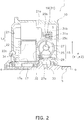
- the power transmission device 1 is provided with a motor 13 (one example of an electric motor) and a torque converter 15, as shown in FIG. 2 .
- the power transmission device 1 is provided with a casing 10, the motor 13, and the torque converter 15.
- the power transmission device 1 is further provided with a rotation transmission structure 17.
- the power transmission device 1 is further provided with a lock-up structure 19.
- the casing 10 is attached to the vehicle body.
- the casing 10 has an internal space S.
- the motor 13 is a drive part of the power transmission device 1.
- the motor 13 is disposed in the internal space S of the casing 10, as shown in FIG. 2 .
- the motor 13 has a first stator 21 (one example of a stator) and a rotor 22.
- the first stator 21 is secured to the casing 10.
- a coil part 21a is provided to the first stator 21.
- the rotor 22 is configured to be capable of rotating relative to the first stator 21.
- the rotor 22 is supported to be capable of rotating relative to the first output shaft 5.
- the rotor 22 is supported through the rotation transmission structure 17 to be capable of rotating relative to the first output shaft 5.
- the rotor 22 is positioned along an axial direction by a positioning member 34.
- the positioning member 34 is attached to the rotor 22 so as to be capable of rotating integrally with the rotor 22, and is supported on the first output shaft 5 so as to be capable of rotating relative to the first output shaft 5.
- the rotor 22 has a permanent magnet. Specifically, the rotor 22 is provided with a magnet part 22a in which an N pole and an S pole are alternatingly disposed in a circumferential direction. The magnet part 22a is configured from a permanent magnet.
- a current is supplied to the coil part 21a of the first stator 21 from the battery unit 3 (see FIG. 1 ), and when a magnetic field is generated between the coil part 21a and the magnet part 22a, the rotor 22 rotates relative to the first stator 21 about a rotational axis of the first output shaft 5.
- the current from the battery unit 3 is controlled by the control unit, whereby the rotation of the rotor 22 is controlled.
- the motor 13 functions as a permanent magnet synchronous motor because the magnet part 22a having a permanent magnet is included in the rotor 22. Due to the motor 13 being configured in this manner, the motor 13 forms an efficiency map (see FIGS. 3A and 3B described hereinafter) having, for example, high-efficiency regions E1, E2 (see FIG. 4 , described hereinafter) in the center.
- the torque converter 15 is connected to the motor 13.
- the torque converter 15 transmits drive force of the motor 13 to the first output shaft 5.
- the torque converter 15 transmits the rotation of the rotor 22 to the first output shaft 5 when the rotor 22 rotates in a drive direction R1 (see FIG. 1 ).
- the drive direction R1 is a direction in which the rotor 22 is caused to rotate in order to move the vehicle forward.
- the torque converter 15 is disposed inside the casing 10, i.e., in the internal space S of the casing 10, as shown in FIG. 2 .
- the torque converter 15 has an impeller 25, a turbine 27, and a second stator 29.
- the torque converter 15 causes the impeller 25, the turbine 27, and the second stator 29 to rotate via hydraulic oil, whereby torque inputted to the impeller 25 is transmitted to the turbine 27.
- the impeller 25 is configured to be capable of rotating integrally with the rotor 22.
- the impeller 25, e.g., an impeller shell 25a, is secured to a cover part 32.
- a torque converter case is formed by the impeller shell 25a and the cover part 32 secured to the rotor 22.
- the torque converter case is a non-magnetic body.
- the turbine 27 is linked to the first output shaft 5.
- the turbine 27 is linked to be capable of rotating integrally with the first output shaft 5.
- a turbine shell 27a of the turbine 27 is disposed between the impeller shell 25a and the cover part 32.
- the second stator 29 is configured to be capable of rotating relative to the casing 10.
- the second stator 29 is disposed to be capable of rotating relative to the casing 10 by means of a one-way clutch 30.
- the rotation transmission structure 17 selectively transmits the rotation of the rotor 22 to the first output shaft 5.
- the rotation transmission structure 17 is disposed in the internal space S of the casing 10, between the rotor 22 and the first output shaft 5, as shown in FIG. 2 .
- the rotation transmission structure 17 has a one-way clutch 17a.
- the one-way clutch 17a when the rotor 22 rotates in the drive direction R1, the one-way clutch 17a does not transmit the rotation of the rotor 22 to the first output shaft 5. Conversely, when the rotor 22 rotates in a counter-drive direction R2 (see FIG. 1 ), the one-way clutch 17a transmits the rotation of the rotor 22 to the first output shaft 5.
- the counter-drive direction R2 is a rotational direction opposite from the drive direction R1.
- the lock-up structure 19 is disposed in the internal space S of the casing 10.
- the lock-up structure 19 links the impeller 25 and the turbine 27 so as to enable integrated rotation therebetween.
- the lock-up structure 19 has a centrifugal clutch 31, as shown in FIG. 2 .
- a centrifugal element 31a of the centrifugal clutch 31 is provided to the turbine 27, e.g., to the turbine shell 27a.
- a plurality of centrifugal elements 31a configuring the centrifugal clutch 31 are disposed at intervals along the circumferential direction (rotational direction), and are held on the turbine shell 27a so as to be capable of moving radially relative to the turbine shell 27a and capable of rotating integrally with the turbine shell 27a.
- the plurality of centrifugal elements 31a are disposed facing a radially outward side part 25b of the impeller shell 25a.
- a friction member 31b is provided to each of the plurality of centrifugal elements 31a.
- the friction members 31b of the centrifugal elements 31a are disposed at intervals away from the radially outward side part 25b of the impeller shell 25a.
- the plurality of centrifugal elements 31a are disposed at intervals away from the radially outward side part 25b of the impeller shell 25a. This state is a clutch OFF state.
- a state in which the friction members 31b of the centrifugal elements 31a are in contact with the radially outward side part 25b of the impeller shell 25a is a clutch ON state.
- the centrifugal force acting on the plurality of centrifugal elements 31a is equal to or greater than the predetermined centrifugal force
- the plurality of centrifugal elements 31a come into contact with the radially outward side part 25b of the impeller shell 25a.
- the impeller 25 and the turbine 27 are thereby linked so as to be capable of rotating integrally.
- This state is the clutch ON state.
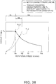
- FIGS. 3A and 3B are graphs showing characteristics of the motor 13 and the torque converter 15, in which the horizontal axis represents rotational speed V (r/min) and the vertical axis represents torque T (Nm).
- the solid lines in FIGS. 3A and 3B indicate a characteristic line ML for the motor when the motor 13 is actuated alone, as well as indicating a relationship between rotational speed V and output torque T in the motor 13. Specifically, the solid lines indicate a characteristic line ML for the motor when the motor 13 is actuated alone, as well as indicating the output torque T relative to each rotational speed V in the motor 13.
- the phrase "when the motor 13 is actuated alone” includes the meaning of "when the motor 13 is actuated alone without increasing or reducing speed.”
- a maximum output torque Tm of the motor 13 is kept substantially constant by limiting current in the low-rotational-speed range, e.g., a range in which the rotational speed V is equal to and greater than 0 and is equal to and less than a base rotational speed Na (0 ⁇ rotational speed ⁇ base rotational speed Na).
- the current flowing to the coil part 21a of the first stator 21 is reduced by a counter electromotive voltage as the rotational speed V of the motor 13 increases. Therefore, the maximum output torque T (T ⁇ Tm) of the motor 13 decreases.
- the efficiency map of the motor 13 indicates a distribution of the efficiency of the motor 13, as shown in FIG. 4 .
- the efficiency of the motor 13 is defined by a ratio of mechanical output (W) from the motor 13 to input electric power (W) inputted to the motor 13.
- motor efficiency mechanical output W / input electric power W ⁇ 100 %
- input electric power voltage V ⁇ current
- mechanical output rotational speed r / min ⁇ torque Nm
- the single-dash lines in FIGS. 3A and 3B indicate a characteristic line TL for the torque converter 15, as well as indicating a relationship between rotational speed V and torque T in the torque converter 15. Specifically, the single-dash lines correspond to a capacity coefficient Y (Y1 and Y2, described hereinafter) in the torque converter 15.
- the input rotational speed V of the torque converter 15 is a rotational speed inputted from the motor 13 to the torque converter 15.
- the input torque T of the torque converter 15 is the torque inputted from the motor 13 to the torque converter 15.
- the characteristic line TL (TL1 and TL2, described hereinafter) for the torque converter 15 is determined on the basis of the capacity coefficient Y.
- the torque T is proportional to the square of the rotational speed V.
- the capacity coefficient Y is a proportionality coefficient.
- the characteristic line TL for the torque converter 15 thereby draws nearer to the vertical axis as the capacity coefficient Y increases, and draws away from the vertical axis as the capacity coefficient Y decreases.
- the size, e.g., the representative diameter ⁇ of the torque converter 15 is defined on the basis of the capacity coefficient Y.
- the representative diameter ⁇ is an outside diameter of a torus (a fluid operation chamber).
- the capacity coefficient Y is proportional to the fifth power of the size, e.g., the representative diameter ⁇ of the torque converter 15.
- A is a proportionality coefficient and is set to a predetermined value.
- the capacity coefficient Y thereby decreases when the representative diameter ⁇ of the torque converter 15 decreases. In other words, when the capacity coefficient Y decreases, the representative diameter ⁇ of the torque converter 15 decreases.
- the representative diameter ⁇ of the torque converter 15 decreases as the capacity coefficient Y decreases. Additionally, when the capacity coefficient Y, e.g., the representative diameter ⁇ of the torque converter 15, decreases, the characteristic line TL for the torque converter 15 draws away from the vertical axis.
- the capacity coefficient Y1 of the torque converter 15 is such that the characteristic line TL1 for the torque converter 15 intersects the characteristic line ML for the motor in a first range RA.
- the capacity coefficient Y1 is preferably a capacity coefficient in where a speed ratio of the torque converter 15 is zero.
- the speed ratio is defined by, for example, a ratio of a rotational speed of the turbine 27 to a rotational speed of the impeller 25.
- the intersection point of the characteristic line TL1 for the torque converter 15 and the characteristic line ML for the motor is indicated by a black circle.
- the first range RA corresponds to a range equal to and greater than the base rotational speed Na of the motor 13, and equal to or less than a first average rotational speed N1.
- the first average rotational speed N1 is determined by an average of the base rotational speed Na of the motor 13 and the maximum rotational speed Nm of the motor 13.
- the base rotational speed Na of the motor 13 is a speed at which a switch is made from a state in which torque is constant to a state in which the mechanical output described above is constant.
- the characteristic line TL1 for the torque converter 15 is determined on the basis of the capacity coefficient Y1. Specifically, the capacity coefficient Y1, e.g., a representative diameter ⁇ 1 of the torque converter 15, is established such that the characteristic line TL1 for the torque converter 15 intersects the characteristic line ML for the motor in the first range RA.
- the capacity coefficient Y1 e.g., a representative diameter ⁇ 1 of the torque converter 15 is established such that the characteristic line TL1 for the torque converter 15 intersects the characteristic line ML for the motor in the first range RA.
- the characteristic line TL1 for the torque converter 15 draws farther away from the vertical axis than in a case in which the characteristic line TLJ for the torque converter 15 intersects the characteristic line ML for the motor in the range RL which is less than the base rotational speed Na (see FIG. 4 ) as in the prior art.
- the characteristic line TL1 for the torque converter 15 intersects the characteristic line ML for the motor in the first range RA (see FIG. 3A )
- the characteristic line TL2 for the torque converter 15 draws farther away from the vertical axis than in a case in which the characteristic line TLJ for the torque converter 15 intersects the characteristic line ML for the motor in the range RL which is less than the base rotational speed (see FIG. 4 ) as in the prior art.
- the capacity coefficient Y1 is less than the capacity coefficient YJ of the prior art.
- the representative diameter ⁇ 1 is less than a representative diameter ⁇ J of the prior art.
- the torque converter 15 can have a capacity coefficient Y2 such that the characteristic line TL2 for the torque converter 15 intersects the characteristic line ML for the motor in a second range RB, as shown in FIG. 3B .
- the capacity coefficient Y2 is preferably a capacity coefficient in a case in which the speed ratio of the torque converter 15 is zero.
- the second range RB corresponds to a range equal to and greater than the base rotational speed Na of the motor 13, and equal to or less than a second average rotational speed N2.
- the second average rotational speed N2 is determined by an average of the base rotational speed Na of the motor 13 and the first average rotational speed N1 of the motor 13.
- the characteristic line TL2 for the torque converter 15 is determined on the basis of the capacity coefficient Y2. Specifically, the capacity coefficient Y2, e.g., a representative diameter ⁇ 2 of the torque converter 15, is established so that the characteristic line TL2 for the torque converter 15 intersects the characteristic line ML for the motor in the second range RB.
- the capacity coefficient Y2 e.g., a representative diameter ⁇ 2 of the torque converter 15
- the characteristic line TL2 for the torque converter 15 draws farther away from the vertical axis than in a case in which the characteristic line TLJ for the torque converter 15 intersects the characteristic line ML for the motor in the range RL which is less than the base rotational speed (see FIG. 4 ), as in the prior art.
- the capacity coefficient Y2 is less than the capacity coefficient YJ of the prior art.
- the representative diameter ⁇ 2 is less than the representative diameter ⁇ J of the prior art.
- Whether to use the torque converter 15 having the characteristic line TL1 (capacity coefficient Y1 and representative diameter ⁇ 1) shown in FIG. 3A or the torque converter 15 having the characteristic line TL2 (capacity coefficient Y2 and representative diameter ⁇ 2) shown in FIG. 3B as the torque converter 15 is preferably selected in accordance with the efficiency map of the motor 13.
- the characteristic lines TL1, TL2 for the torque converter 15 are caused to intersect the characteristic line ML for the motor as in FIGS. 3A and 3B , the characteristic lines TL1, TL2 for the torque converter 15 pass through a first region E1 in the efficiency map of the motor 13.
- the characteristic lines TL1, TL2 for the torque converter 15 respectively intersect the characteristic line ML for the motor in the first range RA or the second range RB, the characteristic lines pass through the first region E1 and a second region E2 in the efficiency map of the motor 13.
- the first region E1 indicates a region in which, for example, the efficiency of the motor 13 is 85% or greater in the efficiency map of the motor 13.
- the second region E2 indicates a region in which the efficiency of the motor 13 is 90% or greater in the efficiency map of the motor 13.
- the torque converter 15 has the capacity coefficients Y1, Y2 such that the characteristic lines TL1, TL2 for the torque converter 15 respectively pass through the first region E1 (a region of 85%) of the efficiency map of the motor 13, or the first region E1 (a region of 85%) and the second region E2 (a region of 90%) of the efficiency map.
- the motor 13 can be efficiently utilized by causing the characteristic line TL for the torque converter 15 to pass through high-efficiency regions E1, E2 (the first region E1 and/or the second region E2) in the efficiency map of the motor 13. Specifically, torque can be efficiently outputted from the power transmission device 1 to the first output shaft 5.
- the capacity coefficient of the torque converter 15 is preferably 5 to 30 ⁇ 10 -6 (Nm/(r/min) 2 ). It is possible to efficiently utilize the motor 13 while reducing the torque converter 15 in size by configuring the motor 13 and the torque converter 15 using the torque converter 15 having such characteristics. Specifically, torque can be efficiently outputted from the power transmission device 1 to the first output shaft 5 while reducing the torque converter 15 in size.
- the base rotational speed Na is set in a predetermined range DNa.
- the predetermined range DNa is equal to and greater than 1500 (r/min) and is equal to and less than 3000 (r/min).
- the predetermined range DNa is equal to and greater than 2000 (r/min) and is equal to and less than 2500 (r/min).
- the motor 13 is selected such that the base rotational speed Na is included in the predetermined range DNa. In case that the motor 13 is selected such that the base rotational speed Na is not included in the predetermined range DNa, the motor 13 is adjusted such that the base rotational speed Na is included in the predetermined range DNa.
- the characteristic line TL3 of the torque converter 15 is set based on the base rotational speed Na of this motor 13 (or a value near the base rotational speed Na of this motor 13). In other words, the torque converter 15 can be suitably matched to the motor 13 by providing the torque converter 15 including the characteristic line TL3 respect to the motor 13 including the above base rotational speed Na. In other words, the torque converter 15 can be reduced in size.
Abstract
Description
- The present invention relates to a power transmission device for a vehicle.
- Conventional power transmission devices for vehicles are provided with a motor generator (electric motor) and a torque converter (see Patent Literature 1). In this configuration, drive force of the motor generator is transmitted to an output shaft via the torque converter.
- [Patent Literature 1] Japanese Laid-open Patent Publication No.
2011-231857 - Generally, in a conventional power transmission device for a vehicle, a capacity coefficient YJ of a torque converter is set so that a characteristic line TLJ for the torque converter intersects a characteristic line ML for an electric motor in a range RL which is less than a base rotational speed, the characteristic line ML indicating a maximum output torque of a motor generator relative to each rotational speed of the motor generator, as shown in
FIG. 4 . - This is because a maximum output torque Tm of the motor generator in the range RL can be utilized by setting the capacity coefficient YJ of the torque converter so that the characteristic line TLJ for the torque converter intersects the characteristic line ML for the electric motor in the range RL.
- However, there is a risk that the capacity coefficient YJ of the torque converter, e.g., the size (representative diameter ϕJ) of the torque converter, will increase in order to cause the characteristic line TLJ for the torque converter to intersect the characteristic line ML for the electric motor. In this case, the characteristic line TLJ for the torque converter passes through a low-efficiency region in an efficiency map of the motor generator as shown in
FIG. 4 , and a problem is therefore encountered in that the motor generator cannot be efficiently utilized. - The present invention was devised in view of the problem described above, and an object of the present invention is to provide a power transmission device for a vehicle in which the torque converter can be reduced in size. A further object of the present invention is to provide a power transmission device for a vehicle in which an electric motor can be efficiently utilized.
- A power transmission device for a vehicle according to a first aspect of the present invention comprises an electric motor and a torque converter. The torque converter is connected to the electric motor and transmits torque of the electric motor to an output member.
- In this aspect, a characteristic line for the torque converter is determined on the basis of a capacity coefficient of the torque converter. The characteristic line for the torque converter indicates torque of the torque converter relative to each rotational speed of the torque converter. A characteristic line for the electric motor indicates a maximum output torque of the electric motor relative to each rotational speed of the electric motor.
- A first range corresponds to a range that is equal to and greater than a base rotational speed of the electric motor and is equal to or less than a first average rotational speed, which is an average of the base rotational speed of the electric motor and a maximum rotational speed of the electric motor. The torque converter includes a capacity coefficient such that the characteristic line for the torque converter intersects the characteristic line for the electric motor in the first range.
- In the present power transmission device for a vehicle, the first range corresponds to a range that is equal to and greater than the base rotational speed of the electric motor and is equal to or less than the first average rotational speed. Specifically, the first range is greater than a range which is less than the base rotational speed and is equal to or less than the first average rotational speed. Additionally, the maximum output torque of the first range defined by the characteristic line for the electric motor is equal to and less than the maximum output torque in a low-rotational-speed range (0 ≤ rotational speed ≤ base rotational speed) defined by the characteristic line for the electric motor.
- Comparing a first scenario in which the characteristic line for the torque converter intersects the characteristic line for the electric motor in the first range, and a second scenario (conventional scenario) in which the characteristic line for the torque converter intersects the characteristic line for the electric motor in the range which is less than the base rotational speed, the capacity coefficient of the first scenario is less than one of the second scenario.
- By causing the characteristic line for the torque converter to intersect the characteristic line for the electric motor in the first range in this manner, the capacity coefficient of the torque converter can be made less than the capacity coefficient of a conventional torque converter. Specifically, the torque converter can be reduced in size. Additionally, by configuring the power transmission device as described above, the electric motor can be efficiently utilized because the characteristic line for the torque converter can pass through a high-efficiency region of the electric motor.
- A power transmission device for a vehicle according to another aspect of the present invention is preferably configured in the following manner. A second range corresponds to a range that is equal to and greater than the base rotational speed of the electric motor and is equal to or less than a second average rotational speed, which is an average of the base rotational speed of the electric motor and the first average rotational speed of the electric motor. The torque converter includes a capacity coefficient such that the characteristic line for the torque converter intersects the characteristic line for the electric motor in the second range.
- In this configuration, the second range corresponds to a range that is equal to and greater than the base rotational speed of the electric motor and is equal to or less than the second average rotational speed. Specifically, the second range is greater than the range which is less than the base rotational speed, and is equal to or less than the second average rotational speed.
- By causing the characteristic line for the torque converter to intersect the characteristic line for the electric motor in the second range, the capacity coefficient of the torque converter can be made less than the capacity coefficient of a conventional torque converter. Specifically, the torque converter can be reduced in size. Additionally, by configuring the power transmission device as described above, the electric motor can be efficiently utilized because the characteristic line for the torque converter can pass through a high-efficiency region of the electric motor.
- In a power transmission device for a vehicle according to another aspect of the present invention, the capacity coefficient is preferably a capacity coefficient in an instance where a speed ratio of the torque converter is zero. Even with this configuration, the electric motor can be efficiently utilized because the characteristic line for the torque converter can pass through the high-efficiency region of the electric motor.
- In a power transmission device for a vehicle according to another aspect of the present invention, it is preferable that the electric motor has a stator, and a rotor that has a permanent magnet and is configured to be capable of rotating relative to the stator.
- Due to this configuration, at least part of the high-efficiency region of the electric motor is formed in the above-described first region or the above-described second region, and the characteristic line for the torque converter can therefore reliably pass through the high-efficiency region of the electric motor. The electric motor can thereby be efficiently utilized.
- In a power transmission device for a vehicle according to another aspect of the present invention, it is preferable that the base rotational speed is equal to and greater than 1500 (r/min) and is equal to and less than 3000 (r/min). Thereby, the torque converter can be suitably reduced in size.
- In a power transmission device for a vehicle according to another aspect of the present invention, it is preferable that the base rotational speed is equal to and greater than 2000 (r/min) and is equal to and less than 2500 (r/min). Thereby, the torque converter can be suitably reduced in size.
- In a power transmission device for a vehicle according to another aspect of the present invention, it is preferable that the characteristic line for the torque converter is set based on the base rotational speed. Thereby, the torque converter can be suitably matched to the electric motor. In other words, the torque converter can be reduced in size.
- In the power transmission device for a vehicle of present invention, the torque converter can be reduced in size and the electric motor can be efficiently utilized.
-
-
FIG. 1 is a schematic view showing an overall configuration of a vehicle according to the present embodiment; -
FIG. 2 is a cross-sectional view of a power transmission device of the present embodiment; -
FIG. 3A is a graph showing a characteristic of a motor and a characteristic of a torque converter in the power transmission device of the present embodiment; -
FIG. 3B is a graph showing a characteristic of the motor and a characteristic of the torque converter in the power transmission device of the present embodiment; and -
FIG. 4 is a graph showing characteristics of motors and characteristics of torque converters in power transmission devices of the present embodiment and of the prior art. -
FIG. 1 is a schematic view showing an overall configuration of a vehicle in which apower transmission device 1 of the present invention is disposed. A configuration relating to thepower transmission device 1 is described in a simple manner usingFIG. 1 . - Disposed in the vehicle are, for example, the
power transmission device 1, acontrol unit 2, and a battery unit 3, as shown inFIG. 1 . In this embodiment, an example is shown of a case in which thecontrol unit 2 and the battery unit 3 are not included in thepower transmission device 1, but thecontrol unit 2 and/or the battery unit 3 can be included in thepower transmission device 1. - The
power transmission device 1 is fordriving drive wheels 4. Thepower transmission device 1 is installed in a vehicle body (not shown). Thepower transmission device 1 is actuated by electric power from the battery unit 3, and drives thedrive wheels 4 via a first output shaft 5 (one example of an output member) and asecond output shaft 6. Afirst gear part 7 is provided to thefirst output shaft 5. Asecond gear part 8 is provided to thesecond output shaft 6. Thesecond gear part 8 meshes with thefirst gear part 7. Adifferential mechanism 9 is disposed between thesecond output shaft 6 and thedrive wheels 4. - With this configuration, when drive force is transmitted from the
power transmission device 1 to thefirst output shaft 5, the drive force is transmitted from thesecond output shaft 6 to thedrive wheels 4 via thedifferential mechanism 9. Thus, thedrive wheels 4 are driven by thepower transmission device 1. - The term "drive force" includes torque. A power transmission path described above is one example, and the drive force of the
power transmission device 1 can be transmitted to thedrive wheels 4 using another output shaft and/or gear part as well. The details of thepower transmission device 1 are described hereinafter. - The
control unit 2 controls thepower transmission device 1 and the battery unit 3. Thecontrol unit 2 is installed in the vehicle body. Thecontrol unit 2 is actuated by electric power from the battery unit 3. - The battery unit 3 supplies electric power to the
power transmission device 1 and thecontrol unit 2. The battery unit 3 is installed in the vehicle body. The battery unit 3 can be charged by an external power source. The battery unit 3 can also be charged using electric power generated in thepower transmission device 1. - The
power transmission device 1 is for transmitting drive force to thefirst output shaft 5. Thepower transmission device 1 is provided with a motor 13 (one example of an electric motor) and atorque converter 15, as shown inFIG. 2 . Specifically, thepower transmission device 1 is provided with acasing 10, themotor 13, and thetorque converter 15. Thepower transmission device 1 is further provided with arotation transmission structure 17. Thepower transmission device 1 is further provided with a lock-upstructure 19. Thecasing 10 is attached to the vehicle body. Thecasing 10 has an internal space S. - The
motor 13 is a drive part of thepower transmission device 1. Themotor 13 is disposed in the internal space S of thecasing 10, as shown inFIG. 2 . Themotor 13 has a first stator 21 (one example of a stator) and arotor 22. Thefirst stator 21 is secured to thecasing 10. Acoil part 21a is provided to thefirst stator 21. - The
rotor 22 is configured to be capable of rotating relative to thefirst stator 21. Therotor 22 is supported to be capable of rotating relative to thefirst output shaft 5. Specifically, therotor 22 is supported through therotation transmission structure 17 to be capable of rotating relative to thefirst output shaft 5. - The
rotor 22 is positioned along an axial direction by a positioningmember 34. The positioningmember 34 is attached to therotor 22 so as to be capable of rotating integrally with therotor 22, and is supported on thefirst output shaft 5 so as to be capable of rotating relative to thefirst output shaft 5. - The
rotor 22 has a permanent magnet. Specifically, therotor 22 is provided with amagnet part 22a in which an N pole and an S pole are alternatingly disposed in a circumferential direction. Themagnet part 22a is configured from a permanent magnet. - A current is supplied to the
coil part 21a of thefirst stator 21 from the battery unit 3 (seeFIG. 1 ), and when a magnetic field is generated between thecoil part 21a and themagnet part 22a, therotor 22 rotates relative to thefirst stator 21 about a rotational axis of thefirst output shaft 5. The current from the battery unit 3 is controlled by the control unit, whereby the rotation of therotor 22 is controlled. - In the present embodiment, the
motor 13 functions as a permanent magnet synchronous motor because themagnet part 22a having a permanent magnet is included in therotor 22. Due to themotor 13 being configured in this manner, themotor 13 forms an efficiency map (seeFIGS. 3A and3B described hereinafter) having, for example, high-efficiency regions E1, E2 (seeFIG. 4 , described hereinafter) in the center. - The
torque converter 15 is connected to themotor 13. Thetorque converter 15 transmits drive force of themotor 13 to thefirst output shaft 5. Specifically, thetorque converter 15 transmits the rotation of therotor 22 to thefirst output shaft 5 when therotor 22 rotates in a drive direction R1 (seeFIG. 1 ). The drive direction R1 is a direction in which therotor 22 is caused to rotate in order to move the vehicle forward. - The
torque converter 15 is disposed inside thecasing 10, i.e., in the internal space S of thecasing 10, as shown inFIG. 2 . Thetorque converter 15 has animpeller 25, aturbine 27, and asecond stator 29. Thetorque converter 15 causes theimpeller 25, theturbine 27, and thesecond stator 29 to rotate via hydraulic oil, whereby torque inputted to theimpeller 25 is transmitted to theturbine 27. - The
impeller 25 is configured to be capable of rotating integrally with therotor 22. For example, theimpeller 25, e.g., animpeller shell 25a, is secured to acover part 32. A torque converter case is formed by theimpeller shell 25a and thecover part 32 secured to therotor 22. The torque converter case is a non-magnetic body. - The
turbine 27 is linked to thefirst output shaft 5. Theturbine 27 is linked to be capable of rotating integrally with thefirst output shaft 5. Aturbine shell 27a of theturbine 27 is disposed between theimpeller shell 25a and thecover part 32. Thesecond stator 29 is configured to be capable of rotating relative to thecasing 10. For example, thesecond stator 29 is disposed to be capable of rotating relative to thecasing 10 by means of a one-way clutch 30. - The
rotation transmission structure 17 selectively transmits the rotation of therotor 22 to thefirst output shaft 5. Therotation transmission structure 17 is disposed in the internal space S of thecasing 10, between therotor 22 and thefirst output shaft 5, as shown inFIG. 2 . For example, therotation transmission structure 17 has a one-way clutch 17a. - For example, when the
rotor 22 rotates in the drive direction R1, the one-way clutch 17a does not transmit the rotation of therotor 22 to thefirst output shaft 5. Conversely, when therotor 22 rotates in a counter-drive direction R2 (seeFIG. 1 ), the one-way clutch 17a transmits the rotation of therotor 22 to thefirst output shaft 5. The counter-drive direction R2 is a rotational direction opposite from the drive direction R1. - The lock-up
structure 19 is disposed in the internal space S of thecasing 10. The lock-upstructure 19 links theimpeller 25 and theturbine 27 so as to enable integrated rotation therebetween. - The lock-up
structure 19 has a centrifugal clutch 31, as shown inFIG. 2 . Acentrifugal element 31a of the centrifugal clutch 31 is provided to theturbine 27, e.g., to theturbine shell 27a. Specifically, a plurality ofcentrifugal elements 31a configuring the centrifugal clutch 31 are disposed at intervals along the circumferential direction (rotational direction), and are held on theturbine shell 27a so as to be capable of moving radially relative to theturbine shell 27a and capable of rotating integrally with theturbine shell 27a. - The plurality of
centrifugal elements 31a are disposed facing a radiallyoutward side part 25b of theimpeller shell 25a. Afriction member 31b is provided to each of the plurality ofcentrifugal elements 31a. Thefriction members 31b of thecentrifugal elements 31a are disposed at intervals away from the radiallyoutward side part 25b of theimpeller shell 25a. - Specifically, when centrifugal force is not acting on the plurality of
centrifugal elements 31a, or when centrifugal force acting on the plurality ofcentrifugal elements 31a is less than a predetermined centrifugal force, the plurality ofcentrifugal elements 31a (thefriction members 31b) are disposed at intervals away from the radiallyoutward side part 25b of theimpeller shell 25a. This state is a clutch OFF state. - Conversely, a state in which the
friction members 31b of thecentrifugal elements 31a are in contact with the radiallyoutward side part 25b of theimpeller shell 25a is a clutch ON state. Specifically, when the centrifugal force acting on the plurality ofcentrifugal elements 31a is equal to or greater than the predetermined centrifugal force, the plurality ofcentrifugal elements 31a (thefriction members 31b) come into contact with the radiallyoutward side part 25b of theimpeller shell 25a. Theimpeller 25 and theturbine 27 are thereby linked so as to be capable of rotating integrally. This state is the clutch ON state. -
FIGS. 3A and3B are graphs showing characteristics of themotor 13 and thetorque converter 15, in which the horizontal axis represents rotational speed V (r/min) and the vertical axis represents torque T (Nm). - The solid lines in
FIGS. 3A and3B indicate a characteristic line ML for the motor when themotor 13 is actuated alone, as well as indicating a relationship between rotational speed V and output torque T in themotor 13. Specifically, the solid lines indicate a characteristic line ML for the motor when themotor 13 is actuated alone, as well as indicating the output torque T relative to each rotational speed V in themotor 13. The phrase "when themotor 13 is actuated alone" includes the meaning of "when themotor 13 is actuated alone without increasing or reducing speed." - In the characteristic line ML for the motor, a maximum output torque Tm of the
motor 13 is kept substantially constant by limiting current in the low-rotational-speed range, e.g., a range in which the rotational speed V is equal to and greater than 0 and is equal to and less than a base rotational speed Na (0 ≤ rotational speed ≤ base rotational speed Na). - On the other hand, in the characteristic line ML for the motor, at a rotational speed range RM having a rotational speed V greater than the base rotational speed Na of the low-rotational-speed range RL (base rotational speed Na < rotational speed V < maximum rotational speed Nm), the current flowing to the
coil part 21a of thefirst stator 21 is reduced by a counter electromotive voltage as the rotational speed V of themotor 13 increases. Therefore, the maximum output torque T (T < Tm) of themotor 13 decreases. - The efficiency map of the
motor 13 indicates a distribution of the efficiency of themotor 13, as shown inFIG. 4 . The efficiency of themotor 13 is defined by a ratio of mechanical output (W) from themotor 13 to input electric power (W) inputted to themotor 13. - For example, the efficiency of the
motor 13 is expressed as follows:


- The single-dash lines in
FIGS. 3A and3B indicate a characteristic line TL for thetorque converter 15, as well as indicating a relationship between rotational speed V and torque T in thetorque converter 15. Specifically, the single-dash lines correspond to a capacity coefficient Y (Y1 and Y2, described hereinafter) in thetorque converter 15. - The input rotational speed V of the
torque converter 15 is a rotational speed inputted from themotor 13 to thetorque converter 15. The input torque T of thetorque converter 15 is the torque inputted from themotor 13 to thetorque converter 15. - The characteristic line TL (TL1 and TL2, described hereinafter) for the
torque converter 15 is determined on the basis of the capacity coefficient Y. For example, in the characteristic line TL for thetorque converter 15, the torque T is proportional to the square of the rotational speed V. The capacity coefficient Y is a proportionality coefficient. Specifically, the characteristic line TL for thetorque converter 15 is expressed by "T = Y × (V2)." The characteristic line TL for thetorque converter 15 thereby draws nearer to the vertical axis as the capacity coefficient Y increases, and draws away from the vertical axis as the capacity coefficient Y decreases. - The size, e.g., the representative diameter ϕ of the
torque converter 15 is defined on the basis of the capacity coefficient Y. The representative diameter ϕ is an outside diameter of a torus (a fluid operation chamber). For example, the capacity coefficient Y is proportional to the fifth power of the size, e.g., the representative diameter ϕ of thetorque converter 15. Specifically, the capacity coefficient Y is expressed as Y = A × (ϕ 5). In this equation, A is a proportionality coefficient and is set to a predetermined value. The capacity coefficient Y thereby decreases when the representative diameter ϕ of thetorque converter 15 decreases. In other words, when the capacity coefficient Y decreases, the representative diameter ϕ of thetorque converter 15 decreases. - To summarize what is described above, the representative diameter ϕ of the
torque converter 15 decreases as the capacity coefficient Y decreases. Additionally, when the capacity coefficient Y, e.g., the representative diameter ϕ of thetorque converter 15, decreases, the characteristic line TL for thetorque converter 15 draws away from the vertical axis. - In the characteristic graph shown in
FIG. 3A , the capacity coefficient Y1 of thetorque converter 15 is such that the characteristic line TL1 for thetorque converter 15 intersects the characteristic line ML for the motor in a first range RA. The capacity coefficient Y1 is preferably a capacity coefficient in where a speed ratio of thetorque converter 15 is zero. The speed ratio is defined by, for example, a ratio of a rotational speed of theturbine 27 to a rotational speed of theimpeller 25. Hereinafter, the intersection point of the characteristic line TL1 for thetorque converter 15 and the characteristic line ML for the motor is indicated by a black circle. - The first range RA corresponds to a range equal to and greater than the base rotational speed Na of the
motor 13, and equal to or less than a first average rotational speed N1. The first average rotational speed N1 is determined by an average of the base rotational speed Na of themotor 13 and the maximum rotational speed Nm of themotor 13. The base rotational speed Na of themotor 13 is a speed at which a switch is made from a state in which torque is constant to a state in which the mechanical output described above is constant. - The characteristic line TL1 for the
torque converter 15 is determined on the basis of the capacity coefficient Y1. Specifically, the capacity coefficient Y1, e.g., a representative diameter ϕ1 of thetorque converter 15, is established such that the characteristic line TL1 for thetorque converter 15 intersects the characteristic line ML for the motor in the first range RA. - Due to this configuration, in a case in which the characteristic line TL1 for the
torque converter 15 intersects the characteristic line ML for the motor in the first range RA (seeFIG. 3A ), the characteristic line TL1 for thetorque converter 15 draws farther away from the vertical axis than in a case in which the characteristic line TLJ for thetorque converter 15 intersects the characteristic line ML for the motor in the range RL which is less than the base rotational speed Na (seeFIG. 4 ) as in the prior art. - Specifically, in a case in which the characteristic line TL1 for the
torque converter 15 intersects the characteristic line ML for the motor in the first range RA (seeFIG. 3A ), the characteristic line TL2 for thetorque converter 15 draws farther away from the vertical axis than in a case in which the characteristic line TLJ for thetorque converter 15 intersects the characteristic line ML for the motor in the range RL which is less than the base rotational speed (seeFIG. 4 ) as in the prior art. - In this case, the capacity coefficient Y1 is less than the capacity coefficient YJ of the prior art. Specifically, the representative diameter ϕ1 is less than a representative diameter ϕJ of the prior art. Thus, in the present
power transmission device 1, thetorque converter 15 can be reduced in size. - The
torque converter 15 can have a capacity coefficient Y2 such that the characteristic line TL2 for thetorque converter 15 intersects the characteristic line ML for the motor in a second range RB, as shown inFIG. 3B . The capacity coefficient Y2 is preferably a capacity coefficient in a case in which the speed ratio of thetorque converter 15 is zero. - The second range RB corresponds to a range equal to and greater than the base rotational speed Na of the
motor 13, and equal to or less than a second average rotational speed N2. The second average rotational speed N2 is determined by an average of the base rotational speed Na of themotor 13 and the first average rotational speed N1 of themotor 13. - The characteristic line TL2 for the
torque converter 15 is determined on the basis of the capacity coefficient Y2. Specifically, the capacity coefficient Y2, e.g., a representative diameter ϕ2 of thetorque converter 15, is established so that the characteristic line TL2 for thetorque converter 15 intersects the characteristic line ML for the motor in the second range RB. - Due to this configuration, in a case in which the characteristic line TL2 for the
torque converter 15 intersects the characteristic line ML for the motor in the second range RB (seeFIG. 3B ), the characteristic line TL2 for thetorque converter 15 draws farther away from the vertical axis than in a case in which the characteristic line TLJ for thetorque converter 15 intersects the characteristic line ML for the motor in the range RL which is less than the base rotational speed (seeFIG. 4 ), as in the prior art. - In this case, the capacity coefficient Y2 is less than the capacity coefficient YJ of the prior art. Specifically, the representative diameter ϕ2 is less than the representative diameter ϕJ of the prior art. Even with this configuration, in the present
power transmission device 1, thetorque converter 15 can be reduced in size. - Whether to use the
torque converter 15 having the characteristic line TL1 (capacity coefficient Y1 and representative diameter ϕ1) shown inFIG. 3A or thetorque converter 15 having the characteristic line TL2 (capacity coefficient Y2 and representative diameter ϕ2) shown inFIG. 3B as thetorque converter 15 is preferably selected in accordance with the efficiency map of themotor 13. - When the characteristic lines TL1, TL2 for the
torque converter 15 are caused to intersect the characteristic line ML for the motor as inFIGS. 3A and3B , the characteristic lines TL1, TL2 for thetorque converter 15 pass through a first region E1 in the efficiency map of themotor 13. - Specifically, in a state in which the characteristic lines TL1, TL2 for the
torque converter 15 respectively intersect the characteristic line ML for the motor in the first range RA or the second range RB, the characteristic lines pass through the first region E1 and a second region E2 in the efficiency map of themotor 13. - In this embodiment, the first region E1 indicates a region in which, for example, the efficiency of the
motor 13 is 85% or greater in the efficiency map of themotor 13. The second region E2 indicates a region in which the efficiency of themotor 13 is 90% or greater in the efficiency map of themotor 13. - Specifically, the
torque converter 15 has the capacity coefficients Y1, Y2 such that the characteristic lines TL1, TL2 for thetorque converter 15 respectively pass through the first region E1 (a region of 85%) of the efficiency map of themotor 13, or the first region E1 (a region of 85%) and the second region E2 (a region of 90%) of the efficiency map. - Thus, the
motor 13 can be efficiently utilized by causing the characteristic line TL for thetorque converter 15 to pass through high-efficiency regions E1, E2 (the first region E1 and/or the second region E2) in the efficiency map of themotor 13. Specifically, torque can be efficiently outputted from thepower transmission device 1 to thefirst output shaft 5. - In this embodiment, the capacity coefficient of the
torque converter 15 is preferably 5 to 30 × 10-6 (Nm/(r/min)2). It is possible to efficiently utilize themotor 13 while reducing thetorque converter 15 in size by configuring themotor 13 and thetorque converter 15 using thetorque converter 15 having such characteristics. Specifically, torque can be efficiently outputted from thepower transmission device 1 to thefirst output shaft 5 while reducing thetorque converter 15 in size. - The previous embodiment is not provided by way of limitation to the present invention; various modifications or revisions can be made without deviating from the scope of the present invention.
- (A) The configuration of the previous embodiment is not provided by way of limitation to the configuration of the
power transmission device 1, which can be configured in any manner as long as the torque and rotation of themotor 13 can be transmitted to thetorque converter 15. - (B) In the previous embodiment, an example was presented of a case in which the
rotation transmission structure 17 selectively transmits the rotation of therotor 22 to thefirst output shaft 5. In a case in which thisrotation transmission structure 17 is replaced by a rotation support structure and therotor 22 rotates in the drive direction R1 or the counter-drive direction R2, the rotation of therotor 22 can be transmitted to thefirst output shaft 5 via thetorque converter 15. - (C) In the previous embodiment, an example was presented of a case in which the lock-up
structure 19 has the centrifugal clutch 31, but the lock-upstructure 19 can be configured in any manner as long as theimpeller 25 and theturbine 27 can be linked to be capable of rotating integrally. - (D) In the previous embodiment, an example was presented of a case in which the characteristic lines TL1, TL2 for the
torque converter 15 pass through both the first region E1 and the second region E2 in the efficiency map of themotor 13, but the capacity coefficients Y1, Y2 are preferably established so that the characteristic lines TL1, TL2 for thetorque converter 15 pass through at least the first region E1 (a region of 85%). - (E) In the previous embodiment, as shown in
FIG. 3A ,FIG. 3B , andFIG. 4 , the characteristic line TL3 of thetorque converter 15 is set based on the base rotational speed Na of themotor 13. For example, the characteristic line TL3 of thetorque converter 15 intersects the characteristic line ML of themotor 13 on the base rotational speed Na of the motor 13 (or near the base rotational speed Na of the motor 13). - In this case, the base rotational speed Na is set in a predetermined range DNa. For example, it is preferable that the predetermined range DNa is equal to and greater than 1500 (r/min) and is equal to and less than 3000 (r/min). Specifically, it is preferable that the predetermined range DNa is equal to and greater than 2000 (r/min) and is equal to and less than 2500 (r/min).
- The
motor 13 is selected such that the base rotational speed Na is included in the predetermined range DNa. In case that themotor 13 is selected such that the base rotational speed Na is not included in the predetermined range DNa, themotor 13 is adjusted such that the base rotational speed Na is included in the predetermined range DNa. - The characteristic line TL3 of the
torque converter 15 is set based on the base rotational speed Na of this motor 13 (or a value near the base rotational speed Na of this motor 13). In other words, thetorque converter 15 can be suitably matched to themotor 13 by providing thetorque converter 15 including the characteristic line TL3 respect to themotor 13 including the above base rotational speed Na. In other words, thetorque converter 15 can be reduced in size. -
- 1
- Power transmission device
- 13
- Motor
- 15
- Torque converter
- 21
- First stator
- 22
- Rotor
- TL1, TL2
- Characteristic lines for torque converter
- TLJ
- Characteristic line for conventional torque converter
- ML
- Characteristic line ML for electric motor
- RA
- First range
- RB
- Second range
- E1
- First region
- E2
- Second region
- Y1, Y2
- Capacity coefficients
- YJ
- Conventional capacity coefficient
- ϕ1, ϕ2
- Representative diameter
- ϕJ
- Conventional representative diameter
Claims (7)
- A power transmission device for a vehicle, comprising:an electric motor; anda torque converter connected to the electric motor and configured to transmit torque of the electric motor to an output member;a characteristic line for the torque converter is determined on the basis of a capacity coefficient of the torque converter and indicates torque of the torque converter relative to each rotational speed of the torque converter;a characteristic line for the electric motor indicates a maximum output torque of the electric motor relative to each rotational speed of the electric motor;a first range corresponds to a range that is equal to and greater than a base rotational speed of the electric motor and is equal to or less than a first average rotational speed, which is an average of the base rotational speed of the electric motor and a maximum rotational speed of the electric motor; andthe capacity coefficient of the torque converter is such that the characteristic line for the torque converter intersects the characteristic line for the electric motor in the first range.
- The power transmission device for a vehicle according to claim 1, wherein:a second range corresponds to a range that is equal to and greater than the base rotational speed of the electric motor and is equal to or less than a second average rotational speed, which is an average of the base rotational speed of the electric motor and the first average rotational speed of the electric motor, andthe capacity coefficient of the torque converter is such that the characteristic line for the torque converter intersects the characteristic line for the electric motor in the second range.
- The power transmission device for a vehicle according to claim 1 or 2, wherein:
the capacity coefficient is a capacity coefficient in an instance where a speed ratio of the torque converter is zero. - The power transmission device for a vehicle according to any one of claims 1 to 3, wherein:
the electric motor has a stator, and a rotor that has a permanent magnet and that is configured to be capable of rotating relative to the stator. - The power transmission device for a vehicle according to any one of claims 1 to 4, wherein:
the base rotational speed is equal to and greater than 1500 (r/min) and is equal to and less than 3000 (r/min). - The power transmission device for a vehicle according to claim 5, wherein:
the base rotational speed is equal to and greater than 2000 (r/min) and is equal to and less than 2500 (r/min). - The power transmission device for a vehicle according to claim 5 or 6, wherein:
the characteristic line for the torque converter is set based on the base rotational speed.
Applications Claiming Priority (2)
| Application Number | Priority Date | Filing Date | Title |
|---|---|---|---|
| JP2018148812 | 2018-08-07 | ||
| JP2019087750A JP7326014B2 (en) | 2018-08-07 | 2019-05-07 | Power transmission device for vehicle |
Publications (1)
| Publication Number | Publication Date |
|---|---|
| EP3608155A1 true EP3608155A1 (en) | 2020-02-12 |
Family
ID=67262140
Family Applications (1)
| Application Number | Title | Priority Date | Filing Date |
|---|---|---|---|
| EP19185968.5A Pending EP3608155A1 (en) | 2018-08-07 | 2019-07-12 | Power transmission device for vehicle |
Country Status (3)
| Country | Link |
|---|---|
| US (1) | US11161406B2 (en) |
| EP (1) | EP3608155A1 (en) |
| CN (1) | CN110822052A (en) |
Cited By (2)
| Publication number | Priority date | Publication date | Assignee | Title |
|---|---|---|---|---|
| EP4047243A1 (en) * | 2021-02-18 | 2022-08-24 | Alpraaz AB | Hydrokinetic torque converter and powertrain for an electric vehicle compriseing the same |
| WO2022175409A1 (en) * | 2021-02-18 | 2022-08-25 | Alpraaz Ab | Powertrain for an electric vehicle |
Families Citing this family (2)
| Publication number | Priority date | Publication date | Assignee | Title |
|---|---|---|---|---|
| JP7043312B2 (en) | 2018-03-28 | 2022-03-29 | 株式会社エクセディ | Vehicle drive |
| US20240084890A1 (en) * | 2022-04-29 | 2024-03-14 | Exedy Globalparts Corporation | Selectable torque path torque converter |
Citations (3)
| Publication number | Priority date | Publication date | Assignee | Title |
|---|---|---|---|---|
| DE19504935A1 (en) * | 1994-02-23 | 1995-08-24 | Luk Getriebe Systeme Gmbh | Clutch torque transfer system control method in e.g. motor vehicle |
| JP2000161483A (en) * | 1998-11-26 | 2000-06-16 | Toyota Motor Corp | Control device for hybrid car |
| JP2011231857A (en) | 2010-04-27 | 2011-11-17 | Toyota Motor Corp | Driving device |
Family Cites Families (21)
| Publication number | Priority date | Publication date | Assignee | Title |
|---|---|---|---|---|
| JPH0754148B2 (en) * | 1987-12-04 | 1995-06-07 | 日産自動車株式会社 | Torque converter |
| US5045035A (en) * | 1988-01-19 | 1991-09-03 | Ganoung David P | High-efficiency powertrain |
| KR960006313B1 (en) * | 1988-10-25 | 1996-05-13 | 가부시끼가이샤 메이덴샤 | Electric motor powder testing apparatus for automotive power transmission |
| JP2945408B2 (en) * | 1989-04-19 | 1999-09-06 | アイシン・エィ・ダブリュ株式会社 | Torque converter |
| JP3604110B2 (en) * | 1997-04-25 | 2004-12-22 | 株式会社エクセディ | Torque converter stator |
| JP3475717B2 (en) * | 1997-05-22 | 2003-12-08 | 日産自動車株式会社 | Vehicle driving force control device |
| JP3893778B2 (en) * | 1998-11-09 | 2007-03-14 | トヨタ自動車株式会社 | Lock-up clutch control device |
| US6428444B1 (en) * | 1999-09-06 | 2002-08-06 | Toyota Jidosha Kabushiki Kaisha | Apparatus for controlling a vehicle and a method of controlling the vehicle |
| JP2004229371A (en) * | 2003-01-21 | 2004-08-12 | Suzuki Motor Corp | Controller for hybrid car |
| JP4168954B2 (en) * | 2004-02-26 | 2008-10-22 | トヨタ自動車株式会社 | Control device for vehicle drive device |
| US8917611B2 (en) * | 2009-05-07 | 2014-12-23 | Jasper Technologies, Inc. | Core services platform for wireless voice, data and messaging network services |
| DE102007011410A1 (en) * | 2006-03-14 | 2007-11-08 | Mitsubishi Fuso Truck and Bus Corp., Kawasaki | Control unit for a hybrid electric vehicle |
| DE102008020683B4 (en) * | 2007-05-09 | 2019-01-17 | Schaeffler Technologies AG & Co. KG | Torque converter with arrangement for cooling fluid flow and arrangement for transmitting torque to a damper |
| DE102008031010A1 (en) * | 2007-07-11 | 2009-01-15 | Luk Lamellen Und Kupplungsbau Beteiligungs Kg | Two-channel multi-function torque converter |
| JP2009236131A (en) * | 2008-03-25 | 2009-10-15 | Toyota Motor Corp | Control device for torque converter |
| US8340635B2 (en) * | 2009-03-16 | 2012-12-25 | Apple Inc. | Capability model for mobile devices |
| US9132829B2 (en) * | 2011-06-29 | 2015-09-15 | Toyota Jidosha Kabushiki Kaisha | Control device for vehicle drive device |
| US9604525B2 (en) * | 2011-11-14 | 2017-03-28 | Toyota Jidosha Kabushiki Kaisha | Control device for vehicle drive device |
| US9476369B2 (en) * | 2012-04-13 | 2016-10-25 | Toyota Motor Engineering & Manufacturing North America, Inc. | Variable power output and maximum speed in drive mode |
| US8938340B2 (en) * | 2013-03-13 | 2015-01-20 | Ford Global Technologies, Llc | Automatic transmission shift control based on clutch torque capacity detection using calculated transmission input torque |
| JP6281531B2 (en) * | 2015-07-10 | 2018-02-21 | トヨタ自動車株式会社 | Power transmission control device |
-
2019
- 2019-06-19 US US16/445,901 patent/US11161406B2/en active Active
- 2019-07-12 EP EP19185968.5A patent/EP3608155A1/en active Pending
- 2019-07-31 CN CN201910703032.0A patent/CN110822052A/en active Pending
Patent Citations (3)
| Publication number | Priority date | Publication date | Assignee | Title |
|---|---|---|---|---|
| DE19504935A1 (en) * | 1994-02-23 | 1995-08-24 | Luk Getriebe Systeme Gmbh | Clutch torque transfer system control method in e.g. motor vehicle |
| JP2000161483A (en) * | 1998-11-26 | 2000-06-16 | Toyota Motor Corp | Control device for hybrid car |
| JP2011231857A (en) | 2010-04-27 | 2011-11-17 | Toyota Motor Corp | Driving device |
Cited By (2)
| Publication number | Priority date | Publication date | Assignee | Title |
|---|---|---|---|---|
| EP4047243A1 (en) * | 2021-02-18 | 2022-08-24 | Alpraaz AB | Hydrokinetic torque converter and powertrain for an electric vehicle compriseing the same |
| WO2022175409A1 (en) * | 2021-02-18 | 2022-08-25 | Alpraaz Ab | Powertrain for an electric vehicle |
Also Published As
| Publication number | Publication date |
|---|---|
| CN110822052A (en) | 2020-02-21 |
| US20200047611A1 (en) | 2020-02-13 |
| US11161406B2 (en) | 2021-11-02 |
Similar Documents
| Publication | Publication Date | Title |
|---|---|---|
| EP3608155A1 (en) | Power transmission device for vehicle | |
| US9647582B2 (en) | Induction motor-permanent magnet generator tandem configuration starter-generator for hybrid vehicles | |
| CN110315964B (en) | Vehicle drive device | |
| US10862372B2 (en) | Driving apparatus for vehicle | |
| EP2390994A1 (en) | Magnetic gear and power split transmission using such | |
| EP1847411A1 (en) | Hybrid transmission | |
| US10033326B2 (en) | Temperature based electric machine control | |
| EP3863880B1 (en) | A traction control system | |
| JP6330969B2 (en) | Control device | |
| US20190305698A1 (en) | Driving apparatus for vehicle | |
| JP2019172004A5 (en) | ||
| JP2012071731A (en) | Device for driving hybrid motor | |
| JP2019172005A5 (en) | ||
| CN114148158A (en) | Drive device | |
| JP7326014B2 (en) | Power transmission device for vehicle | |
| US11433756B2 (en) | Drive device | |
| US11831221B2 (en) | Drive device | |
| JP2020024035A5 (en) | ||
| JP2011006020A (en) | Drive device of hybrid vehicle | |
| WO2016047271A1 (en) | Vehicle control system | |
| KR970000792A (en) | System and method for driving electric vehicle | |
| JP2022044920A (en) | Drive device | |
| JP2011105188A (en) | Driving device for hybrid vehicle | |
| JP2016201873A (en) | Drive force distribution device | |
| US11146157B2 (en) | Dual rotor electric machine in an automotive application |
Legal Events
| Date | Code | Title | Description |
|---|---|---|---|
| PUAI | Public reference made under article 153(3) epc to a published international application that has entered the european phase |
Free format text: ORIGINAL CODE: 0009012 |
|
| STAA | Information on the status of an ep patent application or granted ep patent |
Free format text: STATUS: THE APPLICATION HAS BEEN PUBLISHED |
|
| AK | Designated contracting states |
Kind code of ref document: A1 Designated state(s): AL AT BE BG CH CY CZ DE DK EE ES FI FR GB GR HR HU IE IS IT LI LT LU LV MC MK MT NL NO PL PT RO RS SE SI SK SM TR |
|
| AX | Request for extension of the european patent |
Extension state: BA ME |
|
| STAA | Information on the status of an ep patent application or granted ep patent |
Free format text: STATUS: REQUEST FOR EXAMINATION WAS MADE |
|
| 17P | Request for examination filed |
Effective date: 20200616 |
|
| RBV | Designated contracting states (corrected) |
Designated state(s): AL AT BE BG CH CY CZ DE DK EE ES FI FR GB GR HR HU IE IS IT LI LT LU LV MC MK MT NL NO PL PT RO RS SE SI SK SM TR |
|
| STAA | Information on the status of an ep patent application or granted ep patent |
Free format text: STATUS: EXAMINATION IS IN PROGRESS |
|
| 17Q | First examination report despatched |
Effective date: 20210625 |