JP2019172004A5 - - Google Patents
Download PDFInfo
- Publication number
- JP2019172004A5 JP2019172004A5 JP2018061144A JP2018061144A JP2019172004A5 JP 2019172004 A5 JP2019172004 A5 JP 2019172004A5 JP 2018061144 A JP2018061144 A JP 2018061144A JP 2018061144 A JP2018061144 A JP 2018061144A JP 2019172004 A5 JP2019172004 A5 JP 2019172004A5
- Authority
- JP
- Japan
- Prior art keywords
- output shaft
- rotor
- rotation
- drive device
- torque converter
- Prior art date
- Legal status (The legal status is an assumption and is not a legal conclusion. Google has not performed a legal analysis and makes no representation as to the accuracy of the status listed.)
- Granted
Links
- 230000005540 biological transmission Effects 0.000 description 22
- 238000010586 diagram Methods 0.000 description 5
- 239000000969 carrier Substances 0.000 description 4
- 239000000696 magnetic material Substances 0.000 description 2
- 230000004048 modification Effects 0.000 description 2
- 238000006011 modification reaction Methods 0.000 description 2
- 239000010720 hydraulic oil Substances 0.000 description 1
- 230000002093 peripheral Effects 0.000 description 1
Images
Description
本発明は、車両用の駆動装置、特に、出力軸に駆動力を伝達するための車両用の駆動装置に関する。 The present invention relates to a drive device for a vehicle, particularly a drive device for a vehicle for transmitting a driving force to an output shaft.
従来の車両用の駆動装置は、モータジェネレーター(電動機)と、トルクコンバータとを、備えている(特許文献1を参照)。この構成では、モータジェネレーターの駆動力が、トルクコンバータを介して、出力軸(20)に伝達される。 A conventional drive device for a vehicle includes a motor generator (electric motor) and a torque converter (see Patent Document 1). In this configuration, the driving force of the motor generator is transmitted to the output shaft (20) via the torque converter.
従来の車両用の駆動装置では、車両が前進する場合には、モータジェネレーターが正回転し、モータジェネレーターの駆動力が、トルクコンバータを介して、出力軸に伝達される。一方で、車両が後進する場合には、モータジェネレーターが逆回転し、モータジェネレーターの駆動力が、トルクコンバータを介して、出力軸に伝達される。 In a conventional vehicle drive device, when the vehicle moves forward, the motor generator rotates in the forward direction, and the driving force of the motor generator is transmitted to the output shaft via the torque converter. On the other hand, when the vehicle moves backward, the motor generator rotates in the reverse direction, and the driving force of the motor generator is transmitted to the output shaft via the torque converter.
この構成では、車両が後進する場合にモータジェネレーターが逆回転すると、トルクコンバータのインペラも逆回転する。ここで、インペラが逆回転する場合、トルクコンバータの構成上、インペラに入力されたトルクを、タービン及びステータを介して、出力軸に適切に伝達できないおそれがある。 In this configuration, when the motor generator rotates in the reverse direction when the vehicle moves backward, the impeller of the torque converter also rotates in the reverse direction. Here, when the impeller rotates in the reverse direction, the torque input to the impeller may not be properly transmitted to the output shaft via the turbine and the stator due to the configuration of the torque converter.
本発明は、上記の問題に鑑みてなされたものであって、本発明の目的は、電動機の駆動力を出力軸に好適に伝達可能な車両用の駆動装置を、提供することにある。 The present invention has been made in view of the above problems, and an object of the present invention is to provide a drive device for a vehicle capable of suitably transmitting the driving force of an electric motor to an output shaft.
本発明の一側面に係る車両用の駆動装置は、出力軸に駆動力を伝達するためのものである。車両用の駆動装置は、筐体と、電動機と、トルクコンバータと、回転伝達構造とを、備える。 The vehicle drive device according to one aspect of the present invention is for transmitting a driving force to an output shaft. The drive device for a vehicle includes a housing, an electric motor, a torque converter, and a rotation transmission structure.
電動機は、筐体に固定される第1ステータと、第1ステータに対して回転可能に構成されるロータとを、有する。トルクコンバータは、ロータが第1回転方向に回転する場合に、ロータの回転を出力軸に伝達する。回転伝達構造は、ロータが第1回転方向とは反対の第2回転方向に回転する場合に、ロータの回転を出力軸に伝達する。 The electric motor has a first stator fixed to the housing and a rotor rotatably configured with respect to the first stator. The torque converter transmits the rotation of the rotor to the output shaft when the rotor rotates in the first rotation direction. The rotation transmission structure transmits the rotation of the rotor to the output shaft when the rotor rotates in the second rotation direction opposite to the first rotation direction.
本車両用の駆動装置では、ロータが第1回転方向に回転する場合、ロータの回転が、トルクコンバータを介して、出力軸に伝達される。一方で、ロータが第2回転方向に回転する場合、ロータの回転が、回転伝達構造を介して、出力軸に伝達される。すなわち、本車両用の駆動装置では、ロータの回転が、ロータの回転方向に応じて、トルクコンバータ又は回転伝達構造によって、出力軸に伝達される。これにより、電動機の駆動力を出力軸に好適に伝達することができる。 In the drive device for this vehicle, when the rotor rotates in the first rotation direction, the rotation of the rotor is transmitted to the output shaft via the torque converter. On the other hand, when the rotor rotates in the second rotation direction, the rotation of the rotor is transmitted to the output shaft via the rotation transmission structure. That is, in the drive device for this vehicle, the rotation of the rotor is transmitted to the output shaft by the torque converter or the rotation transmission structure according to the rotation direction of the rotor. As a result, the driving force of the electric motor can be suitably transmitted to the output shaft.
本発明の他の側面に係る車両用の駆動装置では、回転伝達構造は、ロータが第2回転方向に回転する場合にロータの回転を出力軸に伝達するクラッチ部を、有することが好ましい。 In the vehicle drive device according to another aspect of the present invention, the rotation transmission structure preferably includes a clutch portion that transmits the rotation of the rotor to the output shaft when the rotor rotates in the second rotation direction.
この構成では、ロータが第2回転方向に回転する場合に、ロータの回転が、クラッチ部を介して、出力軸に伝達される。これにより、電動機の駆動力を出力軸に好適に伝達することができる。 In this configuration, when the rotor rotates in the second rotation direction, the rotation of the rotor is transmitted to the output shaft via the clutch portion. As a result, the driving force of the electric motor can be suitably transmitted to the output shaft.
本発明の他の側面に係る車両用の駆動装置では、回転伝達構造は、遊星歯車機構を有することが好ましい。この場合、遊星歯車機構は、ロータが第2回転方向に回転する場合に、ロータの回転を出力軸に伝達する。 In the vehicle drive device according to another aspect of the present invention, the rotation transmission structure preferably has a planetary gear mechanism. In this case, the planetary gear mechanism transmits the rotation of the rotor to the output shaft when the rotor rotates in the second rotation direction.
この構成では、ロータが第2回転方向に回転する場合に、ロータの回転が、遊星歯車機構を介して、出力軸に伝達される。これにより、電動機の駆動力を、遊星歯車機構によって増幅し、出力軸に好適に伝達することができる。 In this configuration, when the rotor rotates in the second rotation direction, the rotation of the rotor is transmitted to the output shaft via the planetary gear mechanism. As a result, the driving force of the electric motor can be amplified by the planetary gear mechanism and appropriately transmitted to the output shaft.
本発明の他の側面に係る車両用の駆動装置では、トルクコンバータは、ロータと一体回転可能に構成されるインペラと、出力軸に連結されるタービンと、筐体に対して回転可能な第2ステータとを、有することが好ましい。 In the vehicle drive according to another aspect of the present invention, the torque converter has an impeller that is integrally rotatable with the rotor, a turbine that is connected to the output shaft, and a second that is rotatable with respect to the housing. It is preferable to have a stator.
この構成によって、ロータが第1回転方向に回転する場合に、電動機の駆動力をトルクコンバータを介して出力軸に好適に伝達することができる。 With this configuration, when the rotor rotates in the first rotation direction, the driving force of the electric motor can be suitably transmitted to the output shaft via the torque converter.
本発明の他の側面に係る車両用の駆動装置では、タービンは、出力軸と一体回転可能に構成されることが好ましい。 In the vehicle drive device according to another aspect of the present invention, it is preferable that the turbine is configured to be integrally rotatable with the output shaft.
このように構成しても、ロータが第1回転方向に回転する場合に、電動機の駆動力をトルクコンバータを介して出力軸に好適に伝達することができる。 Even with this configuration, when the rotor rotates in the first rotation direction, the driving force of the electric motor can be suitably transmitted to the output shaft via the torque converter.
本発明の他の側面に係る車両用の駆動装置では、タービンは、第1回転方向において出力軸と一体回転可能に構成され、第2回転方向において出力軸に対して回転可能に構成されることが好ましい。 In the vehicle drive device according to another aspect of the present invention, the turbine is configured to be rotatable integrally with the output shaft in the first rotation direction and rotatable with respect to the output shaft in the second rotation direction. Is preferable.
このように構成しても、ロータが第1回転方向に回転する場合に、電動機の駆動力をトルクコンバータを介して出力軸に好適に伝達することができる。 Even with this configuration, when the rotor rotates in the first rotation direction, the driving force of the electric motor can be suitably transmitted to the output shaft via the torque converter.
本発明の他の側面に係る車両用の駆動装置は、インペラとタービンとを一体回転可能に連結するロックアップ構造を、さらに備えることが好ましい。 The vehicle drive device according to another aspect of the present invention preferably further includes a lockup structure that integrally rotatably connects the impeller and the turbine.
この構成によって、ロータが第1回転方向に回転する場合に、電動機の駆動力を出力軸に好適に伝達することができる。 With this configuration, when the rotor rotates in the first rotation direction, the driving force of the electric motor can be suitably transmitted to the output shaft.
本発明の他の側面に係る車両用の駆動装置では、トルクコンバータのケース部は、非磁性体であることが好ましい。 In the vehicle drive device according to another aspect of the present invention, the case portion of the torque converter is preferably a non-magnetic material.
この構成によって、電動機からトルクコンバータへの磁力漏れを防止することができる。すなわち、電動機を好適に作動させることができる。 With this configuration, it is possible to prevent magnetic force leakage from the electric motor to the torque converter. That is, the electric motor can be operated suitably.
本発明では、車両用の駆動装置において、電動機の駆動力を出力軸に好適に伝達できる。 In the present invention, in the driving device for a vehicle, the driving force of the electric motor can be suitably transmitted to the output shaft.
〔第1実施形態〕
<全体概要>
図1は、本発明の駆動装置1が配置された車両の全体構成を示す模式図である。図1を用いて、駆動装置1に関係する構成について、簡単に説明する。
[First Embodiment]
<Overview>
FIG. 1 is a schematic view showing an overall configuration of a vehicle in which the
図1に示すように、車両には、例えば、駆動装置1と、制御ユニット2と、バッテリユニット3とが、配置される。なお、ここでは、制御ユニット2及びバッテリユニット3が、駆動装置1に含まれない場合の例を示すが、制御ユニット2及びバッテリユニット3は駆動装置1に含まれていてもよい。
As shown in FIG. 1, for example, a
駆動装置1は、駆動輪4を駆動するためのものである。駆動装置1は、車両本体(図示しない)に装着される。駆動装置1は、バッテリユニット3からの電力によって動作し、第1出力軸5(出力軸の一例)及び第2出力軸6を介して駆動輪4を駆動する。第1出力軸5には、第1ギア部7が設けられている。第2出力軸6には、第2ギア部8が設けられている。第2ギア部8は、第1ギア部7に噛み合う。第2出力軸6及び駆動輪4の間には、差動機構9が配置されている。
The
この構成によって、駆動装置1から第1出力軸5に駆動力が伝達されると、この駆動力は、差動機構9を介して、第2出力軸6から駆動輪4の駆動軸へと伝達される。このようにして、駆動輪4は、駆動装置1によって駆動される。
With this configuration, when a driving force is transmitted from the
なお、上述した動力伝達経路は一例であって、他の出力軸やギア部をさらに用いて、駆動装置1の駆動力を駆動輪4に伝達してもよい。駆動装置1の詳細については、後述される。
The power transmission path described above is an example, and the driving force of the
制御ユニット2は、駆動装置1及びバッテリユニット3を、制御する。制御ユニット2は、車両本体に装着される。制御ユニット2は、バッテリユニット3からの電力によって、動作する。
The control unit 2 controls the
バッテリユニット3は、駆動装置1及び制御ユニット2に電力を供給する。バッテリユニット3は、車両本体に装着される。バッテリユニット3は、外部電源によって充電可能である。また、バッテリユニット3は、駆動装置1において発生した電力を用いて、充電可能である。
The battery unit 3 supplies electric power to the
<駆動装置>
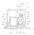
駆動装置1は、第1出力軸5に駆動力を伝達するためのものである。図2に示すように、駆動装置1は、筐体10と、モータ13(電動機の一例)と、トルクコンバータ15とを、備える。駆動装置1は、回転伝達構造17を、さらに備える。駆動装置1は、ロックアップ構造19をさらに備える。筐体10は、車両本体に取り付けられる。筐体10は、内部空間Sを有する。
<Drive device>
The
(モータ)
モータ13は、駆動装置1の駆動部である。図2及び図3に示すように、モータ13は、筐体10の内部空間Sに配置される。モータ13は、第1ステータ21と、ロータ22とを、有する。第1ステータ21は、筐体10に固定される。第1ステータ21には、コイル部21aが設けられている。
(motor)
The
ロータ22は、第1ステータ21に対して回転可能に構成される。ロータ22は、第1出力軸5に対して回転可能に支持されている。詳細には、ロータ22は、回転伝達構造17を介して、第1出力軸5に対して回転可能に支持されている。ロータ22は、位置決め部材34によって軸方向に位置決めされている。位置決め部材34は、ロータ22と一体回転可能なようにロータ22に取り付けられ、且つ第1出力軸5に対して回転可能なように第1出力軸5に支持されている。ロータ22には、N極及びS極が周方向に交互に配置された磁石部22aが、設けられている。
The
第1ステータ21のコイル部21aにバッテリユニット3から電流を供給し、コイル部21a及び磁石部22aの間に磁界を発生させることによって、ロータ22は、第1出力軸5の回転軸心まわりに第1ステータ21に対して回転する。ロータ22の回転は、バッテリユニット3からの電流を制御ユニット2によって制御することによって、制御される。
By supplying a current from the battery unit 3 to the
(トルクコンバータ)
トルクコンバータ15は、モータ13の駆動力を第1出力軸5に伝達する。詳細には、トルクコンバータ15は、ロータ22が駆動方向R1(第1回転方向の一例;図1を参照)に回転する場合に、ロータ22の回転を第1出力軸5に伝達する。ここで、駆動方向R1は、車両を前進させるためにロータ22を回転させる方向である。
(Torque converter)
The
図2及び図3に示すように、トルクコンバータ15は、筐体10の内部すなわち筐体10の内部空間Sに、配置される。トルクコンバータ15は、インペラ25と、タービン27と、第2ステータ29とを、有する。トルクコンバータ15は、作動油を介してインペラ25、タービン27、及び第2ステータ29を回転させることによって、インペラ25に入力されたトルクを、タービン27に伝達する。
As shown in FIGS. 2 and 3, the
インペラ25は、ロータ22と一体回転可能に構成される。例えば、インペラ25例えばインペラシェル25aはカバー部32に固定されており、カバー部32はロータ22に固定されている。インペラ25のインペラシェル25aと、ロータ22に固定されたカバー部32とによって、トルコンケース(ケース部の一例)が形成されている。トルコンケースは、非磁性体である。
The
タービン27は、第1出力軸5に連結される。ここでは、タービン27は、第1出力軸5と一体回転可能に連結される。タービン27のタービンシェル27aは、インペラシェル25aとカバー部32との間に配置される。第2ステータ29は、筐体10に対して回転可能に構成される。例えば、第2ステータ29は、ワンウェイクラッチ30を介して、筐体10に対して回転可能に配置される。
The
(回転伝達構造)
回転伝達構造17は、ロータ22の回転を第1出力軸5に選択的に伝達する。図2及び図3に示すように、回転伝達構造17は、筐体10の内部空間Sにおいて、ロータ22と第1出力軸5との間に配置される。例えば、回転伝達構造17は、ワンウェイクラッチ17a(クラッチ部の一例)を、有する。
(Rotation transmission structure)
The
例えば、ロータ22が駆動方向R1に回転する場合には、ワンウェイクラッチ17aは、ロータ22の回転を第1出力軸5には伝達しない。一方で、ロータ22が反駆動方向R2(第2回転方向の一例;図1を参照)に回転する場合には、ワンウェイクラッチ17aは、ロータ22の回転を第1出力軸5に伝達する。ここで、反駆動方向R2は、駆動方向R1とは反対の回転方向である。
For example, when the
(ロックアップ構造)
ロックアップ構造19は、筐体10の内部空間Sに配置される。ロックアップ構造19は、インペラ25とタービン27とを一体回転可能に連結する。
(Lock-up structure)
The
ここでは、図2及び図3に示すように、ロックアップ構造19は、遠心クラッチ31を有している。遠心クラッチ31の遠心子31aは、タービン27例えばタービンシェル27aに、設けられる。詳細には、遠心クラッチ31を構成する複数の遠心子31aそれぞれは、周方向(回転方向)に間隔を隔てて配置され、径方向に移動可能且つタービンシェル27aと一体回転可能にタービンシェル27aに保持されている。
Here, as shown in FIGS. 2 and 3, the
複数の遠心子31aは、インペラシェル25aの径方向外側部25bに対向して配置されている。複数の遠心子31aそれぞれには、摩擦部材31bが設けられている。各遠心子31aの摩擦部材31bは、インペラシェル25aの径方向外側部25bと間隔を隔てて配置される。
The plurality of
詳細には、複数の遠心子31aに遠心力が作用していない場合、又は複数の遠心子31aに作用する遠心力が所定の遠心力未満の場合、複数の遠心子31a(摩擦部材31b)はインペラシェル25aの径方向外側部25bと間隔を隔てて配置される。この状態が、クラッチオフ状態である。
Specifically, when no centrifugal force acts on the plurality of
一方で、各遠心子31aの摩擦部材31bがインペラシェル25aの径方向外側部25bに当接した状態が、クラッチオン状態である。詳細には、複数の遠心子31aに作用する遠心力が所定の遠心力以上の場合、複数の遠心子31a(摩擦部材31b)はインペラシェル25aの径方向外側部25bに当接する。これにより、インペラ25とタービン27とが、一体回転可能に連結される。この状態が、クラッチオン状態である。
On the other hand, the clutch-on state is a state in which the
上記のように駆動装置1を構成することによって、ロータ22が駆動方向R1に回転する場合、ロータ22の回転が、トルクコンバータ15を介して、第1出力軸5に伝達される。一方で、ロータ22が反駆動方向R2に回転する場合、ロータ22の回転が、回転伝達構造17例えばワンウェイクラッチ17aを介して、第1出力軸5に伝達される。すなわち、駆動装置1では、ロータ22の回転が、ロータ22の回転方向に応じて、トルクコンバータ15又は回転伝達構造17(ワンウェイクラッチ17a)によって、第1出力軸5に伝達される。これにより、モータ13の駆動力を第1出力軸5に好適に伝達することができる。
By configuring the
〔第2実施形態〕
第2実施形態の構成は、回転伝達構造117の構成を除いて、第1実施形態の構成と実質的に同じである。このため、ここでは、第1実施形態と同じ構成については説明を省略し、第1実施形態と異なる構成についてのみ説明する。なお、第1実施形態と同じ構成については、第1実施形態と同じ符号を付している。
[Second Embodiment]
The configuration of the second embodiment is substantially the same as the configuration of the first embodiment except for the configuration of the rotation transmission structure 117. Therefore, here, the description of the same configuration as that of the first embodiment will be omitted, and only the configuration different from that of the first embodiment will be described. The same components as those in the first embodiment are designated by the same reference numerals as those in the first embodiment.
回転伝達構造117は、ロータ22の回転を第1出力軸5に選択的に伝達する。回転伝達構造17は、筐体10の内部空間Sに配置される。
The rotation transmission structure 117 selectively transmits the rotation of the
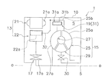
例えば、回転伝達構造117は、遊星歯車機構118を有する。回転伝達構造117は、電磁クラッチ119をさらに有する。 For example, the rotation transmission structure 117 has a planetary gear mechanism 118. The rotation transmission structure 117 further includes an electromagnetic clutch 119.
遊星歯車機構118は、筐体10の内部空間Sにおいて、ロータ22と第1出力軸5との間に配置される。遊星歯車機構118は、リングギア118aと、太陽ギア118bと、遊星ギア118cと、キャリア118dとを、有する。
The planetary gear mechanism 118 is arranged between the
リングギア118aは、径方向外側に配置される。リングギア118aには、ロータ22が固定される。太陽ギア118bは、リングギア118aの内周部に配置される。太陽ギア118bには、電磁クラッチ119が接続される。遊星ギア118cは、リングギア118a及び太陽ギア118bの間に配置される。キャリア118dは、遊星ギア118cを保持する。キャリア118dには、第1出力軸5が固定される。
The ring gear 118a is arranged on the outer side in the radial direction. The
電磁クラッチ119は、筐体10の内部空間Sにおいて、遊星歯車機構118と筐体10との間に配置される。電磁クラッチ119は、ロータ22の回転方向に応じて、遊星歯車機構118を介してロータ22の回転を第1出力軸5に伝達するか否かを、切り換える。
The electromagnetic clutch 119 is arranged between the planetary gear mechanism 118 and the
電磁クラッチ119の移動体119aは、筐体10に設けられる。詳細には、電磁クラッチ119を構成する複数の移動体119aそれぞれは、周方向(回転方向)に間隔を隔てて配置され、径方向に移動可能に筐体10に保持されている。
The moving body 119a of the electromagnetic clutch 119 is provided in the
複数の移動体119aは、筐体10及び太陽ギア118bを連結可能に構成されている。複数の移動体119aは、太陽ギア118bに対向して配置されている。複数の移動体119aそれぞれには、摩擦部材(図示しない)が設けられている。各移動体119a(摩擦部材)は、太陽ギア118bと間隔を隔てて配置される。
The plurality of moving bodies 119a are configured so that the
複数の移動体119aは、制御ユニット2からの命令に基づいて、太陽ギア118bに対して接近又は離反する。複数の移動体119a(摩擦部材)が太陽ギア118bから離反した状態では、遊星歯車機構118は空転し、ロータ22の回転は第1出力軸5に伝達されない。この状態は、電磁クラッチ119によって、筐体10及び太陽ギア118bが連結されていない状態、すなわちクラッチオフ状態である。
The plurality of moving bodies 119a approach or move away from the sun gear 118b based on a command from the control unit 2. When the plurality of moving bodies 119a (friction members) are separated from the sun gear 118b, the planetary gear mechanism 118 idles and the rotation of the
一方で、複数の移動体119aが太陽ギア118bに接近し、複数の移動体119a(摩擦部材)が太陽ギア118bに当接した場合、ロータ22の回転が、遊星歯車機構118を介して、第1出力軸5に伝達される。この状態は、電磁クラッチ119によって、筐体10及び太陽ギア118bが連結された状態、すなわちクラッチオン状態である。
On the other hand, when a plurality of moving bodies 119a approach the sun gear 118b and the plurality of moving bodies 119a (friction members) come into contact with the sun gear 118b, the rotation of the
ここでは、ロータ22が駆動方向R1に回転する場合に、電磁クラッチ119が、クラッチオフになるように、制御ユニット2によって制御される。この場合、ロータ22の回転は、トルクコンバータ15を介して、第1出力軸5に伝達される。
Here, when the
一方で、ロータ22が反駆動方向R2に回転する場合、電磁クラッチ119は、クラッチオンになるように、制御ユニット2によって制御される。この場合、ロータ22の回転は、遊星歯車機構118を介して、第1出力軸5に伝達される。
On the other hand, when the
本実施形態では、ロータ22及び第1出力軸5を、上記のようにリングギア118a及びキャリア118dに各別に固定することによって、ロータ22の駆動力を、遊星歯車機構118において増幅し、第1出力軸5に伝達している。
In the present embodiment, the
このように構成しても、第1実施形態と同様に、ロータ22の回転が、ロータ22の回転方向に応じて、トルクコンバータ15又は回転伝達構造117(遊星歯車機構118)によって、第1出力軸5に伝達される。これにより、モータ13の駆動力を第1出力軸5に好適に伝達することができる。
Even with this configuration, the rotation of the
〔他の実施形態〕
本発明は、前記第1及び第2実施形態に限定されるものではなく、本発明の範囲を逸脱することなく種々の変形又は修正が可能である。
[Other Embodiments]
The present invention is not limited to the first and second embodiments, and various modifications or modifications can be made without departing from the scope of the present invention.
(A)前記第1及び第2実施形態では、タービン27が第1出力軸5と一体回転可能に構成される場合の例を示した。これに代えて、タービン27が、駆動方向R1において第1出力軸5と一体回転可能に構成され、反駆動方向R2において第1出力軸5に対して回転可能に構成されてもよい。
(A) In the first and second embodiments, an example is shown in which the
例えば、図5A及び図5Bに示すように、ワンウェイクラッチ33をタービン27及び第1出力軸5の間に配置してもよい。この場合、タービン27が駆動方向R1に回転する場合、ワンウェイクラッチ33はタービン27及び第1出力軸5を一体回転させる。一方で、タービン27が反駆動方向R2に回転する場合、ワンウェイクラッチ33はタービン27及び第1出力軸5を相対回転させる。
For example, as shown in FIGS. 5A and 5B, the one-way clutch 33 may be arranged between the
(B)前記第1及び第2実施形態では、ロックアップ構造19が遠心クラッチ31を有する場合の例を示したが、インペラ25及びタービン27の連結及び連結解除を上記のように行うことができれば、ロックアップ構造19は他の構造であってもよい。例えば、複数の遠心子31aそれぞれが、タービンシェル27aに揺動可能に保持されてもよい。
(B) In the first and second embodiments, an example in which the
(C)前記第2実施形態では、遊星歯車機構118を制御するために電磁クラッチ119を用いる場合の例を示したが、遊星歯車機構118を上記のように制御することができれば、電磁クラッチ119とは異なるクラッチを用いてもよい。 (C) In the second embodiment, an example in which the electromagnetic clutch 119 is used to control the planetary gear mechanism 118 has been shown. However, if the planetary gear mechanism 118 can be controlled as described above, the electromagnetic clutch 119 is used. A different clutch may be used.
1 駆動装置
5 第1出力軸
10 筐体
13 モータ
15 トルクコンバータ
17,117 回転伝達構造
17a ワンウェイクラッチ
118 遊星歯車機構
119 電磁クラッチ
19 ロックアップ構造
21 第1ステータ
22 ロータ
1 Drive
Priority Applications (3)
| Application Number | Priority Date | Filing Date | Title |
|---|---|---|---|
| JP2018061144A JP7126365B2 (en) | 2018-03-28 | 2018-03-28 | drive for vehicles |
| US16/276,205 US10746273B2 (en) | 2018-03-28 | 2019-02-14 | Driving apparatus for vehicle |
| CN201910231856.2A CN110315964B (en) | 2018-03-28 | 2019-03-25 | Vehicle drive device |
Applications Claiming Priority (1)
| Application Number | Priority Date | Filing Date | Title |
|---|---|---|---|
| JP2018061144A JP7126365B2 (en) | 2018-03-28 | 2018-03-28 | drive for vehicles |
Publications (3)
| Publication Number | Publication Date |
|---|---|
| JP2019172004A JP2019172004A (en) | 2019-10-10 |
| JP2019172004A5 true JP2019172004A5 (en) | 2021-04-30 |
| JP7126365B2 JP7126365B2 (en) | 2022-08-26 |
Family
ID=68055960
Family Applications (1)
| Application Number | Title | Priority Date | Filing Date |
|---|---|---|---|
| JP2018061144A Active JP7126365B2 (en) | 2018-03-28 | 2018-03-28 | drive for vehicles |
Country Status (3)
| Country | Link |
|---|---|
| US (1) | US10746273B2 (en) |
| JP (1) | JP7126365B2 (en) |
| CN (1) | CN110315964B (en) |
Families Citing this family (4)
| Publication number | Priority date | Publication date | Assignee | Title |
|---|---|---|---|---|
| JP7043312B2 (en) | 2018-03-28 | 2022-03-29 | 株式会社エクセディ | Vehicle drive |
| US20220219525A1 (en) * | 2019-05-24 | 2022-07-14 | Exedy Globalparts Corporation | P2 module architecture |
| JP2022044920A (en) * | 2020-09-08 | 2022-03-18 | 株式会社エクセディ | Drive device |
| JP2022044921A (en) * | 2020-09-08 | 2022-03-18 | 株式会社エクセディ | Drive device |
Family Cites Families (19)
| Publication number | Priority date | Publication date | Assignee | Title |
|---|---|---|---|---|
| US5789823A (en) | 1996-11-20 | 1998-08-04 | General Motors Corporation | Electric hybrid transmission with a torque converter |
| DE19923316A1 (en) | 1999-05-21 | 2000-11-23 | Zahnradfabrik Friedrichshafen | Drive system for motor vehicle, having starter- and generator unit sealingly arranged in casing, in area, in which drive shaft, or shaft connected with it, steps through casing |
| JP3570553B2 (en) | 2001-11-20 | 2004-09-29 | 株式会社エクセディ | Torque transmission device |
| JP2004156676A (en) | 2002-11-05 | 2004-06-03 | Yutaka Giken Co Ltd | Power transmission for small vehicle |
| EP1710113B1 (en) * | 2004-04-28 | 2011-07-20 | Aisin Aw Co., Ltd. | Drive device for hybrid vehicle |
| DE102008040498A1 (en) * | 2008-07-17 | 2010-01-21 | Zf Friedrichshafen Ag | Hybrid powertrain of a motor vehicle |
| US8298105B2 (en) * | 2008-09-30 | 2012-10-30 | Aisin Seiki Kabushiki Kaisha | Hybrid drive device |
| JP4981149B2 (en) * | 2010-01-14 | 2012-07-18 | トヨタ自動車株式会社 | Power transmission device |
| JP2011231857A (en) | 2010-04-27 | 2011-11-17 | Toyota Motor Corp | Driving device |
| JP5108071B2 (en) * | 2010-09-22 | 2012-12-26 | 富士重工業株式会社 | Drive device for hybrid vehicle |
| US9121492B2 (en) * | 2011-01-12 | 2015-09-01 | Gm Global Technology Operations, Llc | Hybrid transmission arrangement having a motor damper |
| JP2012240556A (en) | 2011-05-19 | 2012-12-10 | Toyota Motor Corp | Driving force transmission device for hybrid vehicle |
| JP5425163B2 (en) * | 2011-11-04 | 2014-02-26 | アイシン・エィ・ダブリュ株式会社 | Vehicle drive device |
| JP2013245736A (en) | 2012-05-24 | 2013-12-09 | Aisin Seiki Co Ltd | Transmission for electric vehicle |
| US10288159B2 (en) * | 2016-05-13 | 2019-05-14 | GM Global Technology Operations LLC | Integrated clutch systems for torque converters of vehicle powertrains |
| JP6713865B2 (en) * | 2016-07-15 | 2020-06-24 | 株式会社エクセディ | Torque converter |
| JP7043312B2 (en) * | 2018-03-28 | 2022-03-29 | 株式会社エクセディ | Vehicle drive |
| JP2019172005A (en) * | 2018-03-28 | 2019-10-10 | 株式会社エクセディ | Vehicle driving device |
| US20190376589A1 (en) * | 2018-06-07 | 2019-12-12 | GM Global Technology Operations LLC | Parallel Strong Hybrid Electric Vehicle (Hev) Powertrain Assembly With Torque Converter |
-
2018
- 2018-03-28 JP JP2018061144A patent/JP7126365B2/en active Active
-
2019
- 2019-02-14 US US16/276,205 patent/US10746273B2/en active Active
- 2019-03-25 CN CN201910231856.2A patent/CN110315964B/en active Active
Similar Documents
| Publication | Publication Date | Title |
|---|---|---|
| JP7126365B2 (en) | drive for vehicles | |
| JP2019172004A5 (en) | ||
| JP4801175B2 (en) | Hybrid transmission for a hybrid vehicle | |
| JP5703961B2 (en) | In-wheel motor | |
| JP5943127B1 (en) | Vehicle drive device | |
| JP7043312B2 (en) | Vehicle drive | |
| JP2019172006A5 (en) | ||
| US20190305698A1 (en) | Driving apparatus for vehicle | |
| JP2019172005A5 (en) | ||
| US20200047611A1 (en) | Power transmission device for vehicle | |
| US11433755B2 (en) | Drive device | |
| US20210331576A1 (en) | Torque converter | |
| JP7263401B2 (en) | power transmission device | |
| US20220077747A1 (en) | Drive device | |
| US11433756B2 (en) | Drive device | |
| JP7043313B2 (en) | Vehicle drive | |
| JP2022044920A (en) | Drive device | |
| JP2004143993A (en) | Power transmission device for starter/generator | |
| JPWO2020183789A1 (en) | Power transmission device | |
| JP2016210313A (en) | Driving device | |
| JP2020024035A (en) | Power transmission device for vehicle | |
| JP2023024178A (en) | Drive device | |
| JP2020024035A5 (en) | ||
| CN102635631A (en) | A rolling element bearing | |
| JP2023132583A5 (en) |