EP3608141A1 - Transfer - Google Patents
Transfer Download PDFInfo
- Publication number
- EP3608141A1 EP3608141A1 EP17904563.8A EP17904563A EP3608141A1 EP 3608141 A1 EP3608141 A1 EP 3608141A1 EP 17904563 A EP17904563 A EP 17904563A EP 3608141 A1 EP3608141 A1 EP 3608141A1
- Authority
- EP
- European Patent Office
- Prior art keywords
- gear
- output shaft
- input shaft
- shaft
- transfer
- Prior art date
- Legal status (The legal status is an assumption and is not a legal conclusion. Google has not performed a legal analysis and makes no representation as to the accuracy of the status listed.)
- Granted
Links
- 230000007704 transition Effects 0.000 claims description 4
- 238000010586 diagram Methods 0.000 description 16
- 230000000694 effects Effects 0.000 description 10
- 230000007935 neutral effect Effects 0.000 description 8
- 230000004323 axial length Effects 0.000 description 5
- 230000002159 abnormal effect Effects 0.000 description 4
- 230000005540 biological transmission Effects 0.000 description 3
- 239000010687 lubricating oil Substances 0.000 description 2
- 230000004308 accommodation Effects 0.000 description 1
- 230000003247 decreasing effect Effects 0.000 description 1
- 238000012986 modification Methods 0.000 description 1
- 230000004048 modification Effects 0.000 description 1
- 230000002093 peripheral effect Effects 0.000 description 1
- 239000013585 weight reducing agent Substances 0.000 description 1
Images


Classifications
-
- B—PERFORMING OPERATIONS; TRANSPORTING
- B60—VEHICLES IN GENERAL
- B60K—ARRANGEMENT OR MOUNTING OF PROPULSION UNITS OR OF TRANSMISSIONS IN VEHICLES; ARRANGEMENT OR MOUNTING OF PLURAL DIVERSE PRIME-MOVERS IN VEHICLES; AUXILIARY DRIVES FOR VEHICLES; INSTRUMENTATION OR DASHBOARDS FOR VEHICLES; ARRANGEMENTS IN CONNECTION WITH COOLING, AIR INTAKE, GAS EXHAUST OR FUEL SUPPLY OF PROPULSION UNITS IN VEHICLES
- B60K17/00—Arrangement or mounting of transmissions in vehicles
- B60K17/34—Arrangement or mounting of transmissions in vehicles for driving both front and rear wheels, e.g. four wheel drive vehicles
- B60K17/344—Arrangement or mounting of transmissions in vehicles for driving both front and rear wheels, e.g. four wheel drive vehicles having a transfer gear
- B60K17/346—Arrangement or mounting of transmissions in vehicles for driving both front and rear wheels, e.g. four wheel drive vehicles having a transfer gear the transfer gear being a differential gear
- B60K17/3467—Arrangement or mounting of transmissions in vehicles for driving both front and rear wheels, e.g. four wheel drive vehicles having a transfer gear the transfer gear being a differential gear combined with a change speed gearing, e.g. range gear
-
- B—PERFORMING OPERATIONS; TRANSPORTING
- B60—VEHICLES IN GENERAL
- B60K—ARRANGEMENT OR MOUNTING OF PROPULSION UNITS OR OF TRANSMISSIONS IN VEHICLES; ARRANGEMENT OR MOUNTING OF PLURAL DIVERSE PRIME-MOVERS IN VEHICLES; AUXILIARY DRIVES FOR VEHICLES; INSTRUMENTATION OR DASHBOARDS FOR VEHICLES; ARRANGEMENTS IN CONNECTION WITH COOLING, AIR INTAKE, GAS EXHAUST OR FUEL SUPPLY OF PROPULSION UNITS IN VEHICLES
- B60K17/00—Arrangement or mounting of transmissions in vehicles
- B60K17/34—Arrangement or mounting of transmissions in vehicles for driving both front and rear wheels, e.g. four wheel drive vehicles
- B60K17/344—Arrangement or mounting of transmissions in vehicles for driving both front and rear wheels, e.g. four wheel drive vehicles having a transfer gear
-
- F—MECHANICAL ENGINEERING; LIGHTING; HEATING; WEAPONS; BLASTING
- F16—ENGINEERING ELEMENTS AND UNITS; GENERAL MEASURES FOR PRODUCING AND MAINTAINING EFFECTIVE FUNCTIONING OF MACHINES OR INSTALLATIONS; THERMAL INSULATION IN GENERAL
- F16H—GEARING
- F16H37/00—Combinations of mechanical gearings, not provided for in groups F16H1/00 - F16H35/00
- F16H37/02—Combinations of mechanical gearings, not provided for in groups F16H1/00 - F16H35/00 comprising essentially only toothed or friction gearings
- F16H37/06—Combinations of mechanical gearings, not provided for in groups F16H1/00 - F16H35/00 comprising essentially only toothed or friction gearings with a plurality of driving or driven shafts; with arrangements for dividing torque between two or more intermediate shafts
- F16H37/065—Combinations of mechanical gearings, not provided for in groups F16H1/00 - F16H35/00 comprising essentially only toothed or friction gearings with a plurality of driving or driven shafts; with arrangements for dividing torque between two or more intermediate shafts with a plurality of driving or driven shafts
-
- B—PERFORMING OPERATIONS; TRANSPORTING
- B60—VEHICLES IN GENERAL
- B60K—ARRANGEMENT OR MOUNTING OF PROPULSION UNITS OR OF TRANSMISSIONS IN VEHICLES; ARRANGEMENT OR MOUNTING OF PLURAL DIVERSE PRIME-MOVERS IN VEHICLES; AUXILIARY DRIVES FOR VEHICLES; INSTRUMENTATION OR DASHBOARDS FOR VEHICLES; ARRANGEMENTS IN CONNECTION WITH COOLING, AIR INTAKE, GAS EXHAUST OR FUEL SUPPLY OF PROPULSION UNITS IN VEHICLES
- B60K23/00—Arrangement or mounting of control devices for vehicle transmissions, or parts thereof, not otherwise provided for
- B60K23/08—Arrangement or mounting of control devices for vehicle transmissions, or parts thereof, not otherwise provided for for changing number of driven wheels, for switching from driving one axle to driving two or more axles
- B60K23/0808—Arrangement or mounting of control devices for vehicle transmissions, or parts thereof, not otherwise provided for for changing number of driven wheels, for switching from driving one axle to driving two or more axles for varying torque distribution between driven axles, e.g. by transfer clutch
- B60K2023/0816—Arrangement or mounting of control devices for vehicle transmissions, or parts thereof, not otherwise provided for for changing number of driven wheels, for switching from driving one axle to driving two or more axles for varying torque distribution between driven axles, e.g. by transfer clutch for varying front-rear torque distribution with a central differential
- B60K2023/0825—Arrangement or mounting of control devices for vehicle transmissions, or parts thereof, not otherwise provided for for changing number of driven wheels, for switching from driving one axle to driving two or more axles for varying torque distribution between driven axles, e.g. by transfer clutch for varying front-rear torque distribution with a central differential for adding torque to the front wheels
-
- B—PERFORMING OPERATIONS; TRANSPORTING
- B60—VEHICLES IN GENERAL
- B60K—ARRANGEMENT OR MOUNTING OF PROPULSION UNITS OR OF TRANSMISSIONS IN VEHICLES; ARRANGEMENT OR MOUNTING OF PLURAL DIVERSE PRIME-MOVERS IN VEHICLES; AUXILIARY DRIVES FOR VEHICLES; INSTRUMENTATION OR DASHBOARDS FOR VEHICLES; ARRANGEMENTS IN CONNECTION WITH COOLING, AIR INTAKE, GAS EXHAUST OR FUEL SUPPLY OF PROPULSION UNITS IN VEHICLES
- B60K23/00—Arrangement or mounting of control devices for vehicle transmissions, or parts thereof, not otherwise provided for
- B60K23/08—Arrangement or mounting of control devices for vehicle transmissions, or parts thereof, not otherwise provided for for changing number of driven wheels, for switching from driving one axle to driving two or more axles
- B60K2023/085—Arrangement or mounting of control devices for vehicle transmissions, or parts thereof, not otherwise provided for for changing number of driven wheels, for switching from driving one axle to driving two or more axles automatically actuated
- B60K2023/0858—Arrangement or mounting of control devices for vehicle transmissions, or parts thereof, not otherwise provided for for changing number of driven wheels, for switching from driving one axle to driving two or more axles automatically actuated with electric means, e.g. electro-hydraulic means
-
- B—PERFORMING OPERATIONS; TRANSPORTING
- B60—VEHICLES IN GENERAL
- B60K—ARRANGEMENT OR MOUNTING OF PROPULSION UNITS OR OF TRANSMISSIONS IN VEHICLES; ARRANGEMENT OR MOUNTING OF PLURAL DIVERSE PRIME-MOVERS IN VEHICLES; AUXILIARY DRIVES FOR VEHICLES; INSTRUMENTATION OR DASHBOARDS FOR VEHICLES; ARRANGEMENTS IN CONNECTION WITH COOLING, AIR INTAKE, GAS EXHAUST OR FUEL SUPPLY OF PROPULSION UNITS IN VEHICLES
- B60K23/00—Arrangement or mounting of control devices for vehicle transmissions, or parts thereof, not otherwise provided for
- B60K23/08—Arrangement or mounting of control devices for vehicle transmissions, or parts thereof, not otherwise provided for for changing number of driven wheels, for switching from driving one axle to driving two or more axles
-
- B—PERFORMING OPERATIONS; TRANSPORTING
- B60—VEHICLES IN GENERAL
- B60K—ARRANGEMENT OR MOUNTING OF PROPULSION UNITS OR OF TRANSMISSIONS IN VEHICLES; ARRANGEMENT OR MOUNTING OF PLURAL DIVERSE PRIME-MOVERS IN VEHICLES; AUXILIARY DRIVES FOR VEHICLES; INSTRUMENTATION OR DASHBOARDS FOR VEHICLES; ARRANGEMENTS IN CONNECTION WITH COOLING, AIR INTAKE, GAS EXHAUST OR FUEL SUPPLY OF PROPULSION UNITS IN VEHICLES
- B60K5/00—Arrangement or mounting of internal-combustion or jet-propulsion units
- B60K5/02—Arrangement or mounting of internal-combustion or jet-propulsion units with the engine main axis, e.g. crankshaft axis, substantially in or parallel to the longitudinal centre line of the vehicle
-
- B—PERFORMING OPERATIONS; TRANSPORTING
- B60—VEHICLES IN GENERAL
- B60K—ARRANGEMENT OR MOUNTING OF PROPULSION UNITS OR OF TRANSMISSIONS IN VEHICLES; ARRANGEMENT OR MOUNTING OF PLURAL DIVERSE PRIME-MOVERS IN VEHICLES; AUXILIARY DRIVES FOR VEHICLES; INSTRUMENTATION OR DASHBOARDS FOR VEHICLES; ARRANGEMENTS IN CONNECTION WITH COOLING, AIR INTAKE, GAS EXHAUST OR FUEL SUPPLY OF PROPULSION UNITS IN VEHICLES
- B60K6/00—Arrangement or mounting of plural diverse prime-movers for mutual or common propulsion, e.g. hybrid propulsion systems comprising electric motors and internal combustion engines ; Control systems therefor, i.e. systems controlling two or more prime movers, or controlling one of these prime movers and any of the transmission, drive or drive units Informative references: mechanical gearings with secondary electric drive F16H3/72; arrangements for handling mechanical energy structurally associated with the dynamo-electric machine H02K7/00; machines comprising structurally interrelated motor and generator parts H02K51/00; dynamo-electric machines not otherwise provided for in H02K see H02K99/00
- B60K6/20—Arrangement or mounting of plural diverse prime-movers for mutual or common propulsion, e.g. hybrid propulsion systems comprising electric motors and internal combustion engines ; Control systems therefor, i.e. systems controlling two or more prime movers, or controlling one of these prime movers and any of the transmission, drive or drive units Informative references: mechanical gearings with secondary electric drive F16H3/72; arrangements for handling mechanical energy structurally associated with the dynamo-electric machine H02K7/00; machines comprising structurally interrelated motor and generator parts H02K51/00; dynamo-electric machines not otherwise provided for in H02K see H02K99/00 the prime-movers consisting of electric motors and internal combustion engines, e.g. HEVs
- B60K6/22—Arrangement or mounting of plural diverse prime-movers for mutual or common propulsion, e.g. hybrid propulsion systems comprising electric motors and internal combustion engines ; Control systems therefor, i.e. systems controlling two or more prime movers, or controlling one of these prime movers and any of the transmission, drive or drive units Informative references: mechanical gearings with secondary electric drive F16H3/72; arrangements for handling mechanical energy structurally associated with the dynamo-electric machine H02K7/00; machines comprising structurally interrelated motor and generator parts H02K51/00; dynamo-electric machines not otherwise provided for in H02K see H02K99/00 the prime-movers consisting of electric motors and internal combustion engines, e.g. HEVs characterised by apparatus, components or means specially adapted for HEVs
- B60K6/36—Arrangement or mounting of plural diverse prime-movers for mutual or common propulsion, e.g. hybrid propulsion systems comprising electric motors and internal combustion engines ; Control systems therefor, i.e. systems controlling two or more prime movers, or controlling one of these prime movers and any of the transmission, drive or drive units Informative references: mechanical gearings with secondary electric drive F16H3/72; arrangements for handling mechanical energy structurally associated with the dynamo-electric machine H02K7/00; machines comprising structurally interrelated motor and generator parts H02K51/00; dynamo-electric machines not otherwise provided for in H02K see H02K99/00 the prime-movers consisting of electric motors and internal combustion engines, e.g. HEVs characterised by apparatus, components or means specially adapted for HEVs characterised by the transmission gearings
- B60K6/365—Arrangement or mounting of plural diverse prime-movers for mutual or common propulsion, e.g. hybrid propulsion systems comprising electric motors and internal combustion engines ; Control systems therefor, i.e. systems controlling two or more prime movers, or controlling one of these prime movers and any of the transmission, drive or drive units Informative references: mechanical gearings with secondary electric drive F16H3/72; arrangements for handling mechanical energy structurally associated with the dynamo-electric machine H02K7/00; machines comprising structurally interrelated motor and generator parts H02K51/00; dynamo-electric machines not otherwise provided for in H02K see H02K99/00 the prime-movers consisting of electric motors and internal combustion engines, e.g. HEVs characterised by apparatus, components or means specially adapted for HEVs characterised by the transmission gearings with the gears having orbital motion
-
- F—MECHANICAL ENGINEERING; LIGHTING; HEATING; WEAPONS; BLASTING
- F16—ENGINEERING ELEMENTS AND UNITS; GENERAL MEASURES FOR PRODUCING AND MAINTAINING EFFECTIVE FUNCTIONING OF MACHINES OR INSTALLATIONS; THERMAL INSULATION IN GENERAL
- F16D—COUPLINGS FOR TRANSMITTING ROTATION; CLUTCHES; BRAKES
- F16D23/00—Details of mechanically-actuated clutches not specific for one distinct type
- F16D23/12—Mechanical clutch-actuating mechanisms arranged outside the clutch as such
- F16D2023/123—Clutch actuation by cams, ramps or ball-screw mechanisms
Definitions
- the present invention relates to a transfer and more particularly, to an automotive transfer.
- a transfer mounted in an automobile is a device that includes one input shaft and two output shafts and selectively transfers motive power from the input shaft to the two output shafts.
- a transfer which includes an input shaft, a first output shaft, an intermediate shaft, a second output shaft, and a switching device.
- a first gear is amounted on the input shaft.
- a second gear is mounted on the first output shaft, which is disposed on the axis of the input shaft.
- a third gear and a fourth gear are disposed on the intermediate shaft so as to mesh with the first and second gears, respectively.
- a fifth gear is disposed on the second output shaft so as to mesh with the fourth gear.
- the switching device changes gear trains for transmitting motive power.
- the switching device sets the transfer in a two-wheel drive position, a four-wheel high-speed position, or a four-wheel low-speed position.
- Patent Literature 1 Japanese Utility Model Application Publication No. Sho 60(1985)-7450
- the switching device is disposed between the first and third gears and the second and fourth gears. This increases the length of the shaft between the first and third gears and the second and fourth gears, and thus causes a problem in which the transfer lengthens in the axial direction.
- An object of the present invention is to provide a transfer capable of reducing its length in the axial direction.
- a transfer according the present invention includes an input shaft, a first output shaft, an intermediate shaft, and a second output shaft.
- the input shaft receives inputted torque.
- the first output shaft is disposed on the axis of the input shaft and rotatable relative to the input shaft.
- the intermediate shaft is disposed on an axis different from the axis of the input shaft.
- the second output shaft is disposed on an axis different from the axes of the intermediate shaft and input shaft.
- a first gear and a second gear are disposed on either one of the input shaft and first output shaft.
- a third gear and a fourth gear are disposed on the intermediate shaft so as to mesh with the first and second gears, respectively.
- a fifth gear is disposed on the second output shaft so as to mesh with the fourth gear.
- a switching device includes a first device and a second device.
- the first device separably couples the first gear to the input shaft or the first output shaft.
- the second device separably couples the second gear to the input shaft or the first output shaft.
- the first and second gears are disposed axially between the first and second devices.
- the first device separably couples the first gear to the input shaft or the first output shaft
- the second device separably couples the second gear to the input shaft or the first output shaft.
- the first device switches between a state where the input shaft and the first gear are coupled or the first output shaft and the second gear are coupled and a state where the input shaft and the first output shaft are coupled. Therefore, in addition to the advantageous effect provided by Claim 1, it is possible to achieve weight reduction by decreasing the number of parts and simplify the configuration of the switching device.
- the switching device has a position where torque of the input shaft is not transmitted to the first gear and the first output shaft. Therefore, in addition to the advantageous effects provided by any one of Claims 1 to 4, it is possible to obtain a neutral position.
- the first device and the second device are driven in the axial direction due to the rotary motion of cams having the same central axis. Therefore, in addition to the advantageous effects provided by any one of Claims 1 to 5, it is possible to simplify the configuration of the switching device.
- a third device in the switching device separably couples the fourth gear to the intermediate shaft.
- the third device separably couples the second gear to the input shaft or the first output shaft. Therefore, in addition to the advantageous effects provided by any one of Claims 1 to 6, it is possible to separate the fourth gear from each shaft and obtain a neutral position.
- the first device, the second device, and the third device are driven in the axial direction due to the rotary motion of cams having the same central axis. Therefore, in addition to the advantageous effects provided by Claim 7, it is possible to simplify the configuration of the switching device.
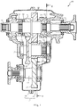
- Fig. 1 is a cross-sectional view including the axis of a transfer 10 according to the first embodiment of the present invention.
- the transfer 10 includes an input shaft 11, a first output shaft 12, an intermediate shaft 13, and a second output shaft 14.
- the input shaft 11 and the first output shaft 12 are disposed on the same axis.
- the intermediate shaft 13 is disposed on an axis different from the axis of the input shaft 11.
- the second output shaft 14 is disposed on an axis different from the axes of the intermediate shaft 13 and input shaft 11.
- the input shaft 11, the first output shaft 12, the intermediate shaft 13, and the second output shaft 14 are rotatably supported by a case 15.
- the case 15 includes a first case 16 and a second case 17.
- the first case 16 accommodates the area of the input shaft 11.
- the second case 17 accommodates the area of the first output shaft 12.
- a space for gear accommodation is formed when the first case 16 and the second case 17 are butted against each other.
- the case 15 is filled with an adequate amount of lubricating oil (not depicted) such that the outer periphery (lower end) of a third gear 23 (described later) is constantly immersed in the lubricating oil.
- the input shaft 11 is linked to an engine or other driving source (not depicted) via, for example, a transmission.
- An end of the first output shaft 12 is relatively rotatably supported by the inside of an end of the input shaft 11.
- the first output shaft 12 is linked, for example, to a rear wheel.
- a first gear 21 and a second gear 22 are relatively rotatably disposed on the first output shaft 12.
- the intermediate shaft 13 is disposed in parallel with the input shaft 11 and the first output shaft 12.
- the third gear 23 and a fourth gear 24 are disposed on the intermediate shaft 13.
- the third gear 23 is in constant mesh with the first gear 21.
- the fourth gear 24 is in constant mesh with the second gear 22.
- the third gear 23 is coupled to the intermediate shaft 13.
- the fourth gear 24 is rotatably disposed on the intermediate shaft 13.
- the second output shaft 14 is disposed in parallel with the input shaft 11, the first output shaft 12, and the intermediate shaft 13.
- the second output shaft 14 is linked, for example, to a front wheel.
- a fifth gear 25 in constant mesh with the fourth gear 24 is disposed on the second output shaft 14.
- the fifth gear 25 is coupled to the second output shaft 14.
- a hub 31 is coupled to the input shaft 11.
- Splines 32, 33 are arranged in the axial direction of the hub 31.
- the spline 32 is coupled to the first output shaft 12, and the spline 33 is coupled to the first gear 21.
- a sleeve 54 (see Fig. 4 ) of a first device 51 (described later) is disposed on the outer peripheries of the hub 31 and splines 32, 33. When a shift fork (not depicted) moves, the sleeve 54 slides in the axial direction while meshing with the hub 31 and the splines 32, 33.
- a spline 34 is coupled to the second gear 22.
- a spline 35 is lined up in the axial direction of the spline 34.
- the spline 35 is coupled to the first output shaft 12.
- a sleeve 56 (see Fig. 4 ) of a second device 52 (described later) is disposed on the outer peripheries of the splines 34, 35. When a shift fork 45 (described later) moves, the sleeve 56 slides in the axial direction while meshing with the splines 34, 35.
- a spline 36 is coupled to the fourth gear 24.
- a spline 37 is lined up in the axial direction of the spline 36.
- the spline 37 is coupled to the intermediate shaft 13.
- a sleeve 55 of a third device 53 (described later) is disposed on the outer peripheries of the splines 36, 37. When a shift fork 42 (described later) moves, the sleeve 55 slides in the axial direction while meshing with the splines 36, 37.
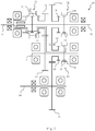
- Fig. 2 is a cross-sectional view of the transfer 10 taken along line II-II in FIG. 1 .
- Fig. 2 does not depict the splines 34, 35, 36, 37, the sleeves 55, 56, and the tooth profiles of the second gear 22, third gear 23, and fifth gear 25.
- the transfer 10 includes a switching device 40 that changes gear trains for transmitting motive power.
- the switching device 40 includes the first device 51 (see Fig. 4 ), the second device 52, and the third device 53.
- the switching device 40 includes the first output shaft 12, fork shafts 41, 44, and a drum 47 (cylindrical cam).
- the fork shafts 41, 44 are disposed in parallel with the intermediate shaft 13 and the second output shaft 14.
- the drum 47 has cams 48, 49 that are formed in a groove on a peripheral cylindrical surface.
- the fork shaft 41 slidably supports the shift fork 42 of the third device 53.
- a pin 43 is swingably coupled to the shift fork 42 and attached to the cam 48.
- the fork shaft 44 slidably supports the shift fork 45 of the second device 52.
- a pin 46 is swingably coupled to the shift fork 45 and attached to the cam 49.
- the fork shaft 44 slidably supports the shift fork (existing behind the second gear 22 as viewed in Fig. 2 ) of the first device 51 (see Fig. 4 ) as well.
- a pin (not depicted) is swingably coupled to that shift fork and attached to a cam groove of the drum 47 (cylindrical cam).
- a motor or other actuator causes the drum 47 to rotate around a central axis 50 parallel to the fork shafts 41, 44.
- the pins 43, 46 are driven along a preset cam curve so that the shift forks 42, 45 move in the axial direction (in the vertical direction as viewed in Fig. 2 ).
- the sleeves 54, 55, 56 of the first device 51 (see Fig. 4 ), second device 52, and third device 53 engage with the shift forks. Therefore, when the shift forks 42, 45 move, the sleeves 54, 55, 56 sequentially move in the axial direction.
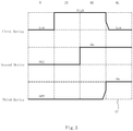
- Fig. 3 is a diagram illustrating the relationship between the switching device 40 and various positions of the transfer 10. As illustrated in Fig. 3 , the positions of the first device 51, second device 52, and third device 53 are switched along the cam curve of the drum 47. Accordingly, the transfer 10 selects a two-wheel drive position (2H), a neutral position (N), a four-wheel high-speed position (4H), or a four-wheel low-speed position (4L) .
- Fig. 4 is a skeleton diagram illustrating the transfer 10 in the two-wheel drive position (2H).
- a broken line in Fig. 4 represents a power transmission path (the same holds true for Figs. 5 to 7 ).
- the first device 51 is switched to HIGH (a state where the input shaft 11 is connected to the first output shaft 12), and the second device 52 and the third device 53 are switched to OFF (see Fig. 3 ).
- Fig. 5 is a skeleton diagram illustrating the transfer 10 in the neutral position (N).
- the first device 51 is switched to Low (a state where the input shaft 11 is connected to the first gear 21), and the second device 52 and the third device 53 are switched to OFF (see Fig. 3 ).
- the sleeve 54 of the first device 51 engages with the hub 31 and the spline 33, and the sleeve 55 of the third device 53 and the sleeve 56 of the second device 52 engage with only the splines 35, 37. Accordingly, the torque of the input shaft 11 is transmitted to the first gear 21 via the sleeve 54.
- the first gear 21 idles on the first output shaft 12.
- the third gear 23 meshing with the first gear 21 rotates.
- the fourth gear 24 idles on the intermediate shaft 13. Therefore, no torque is transmitted to the first output shaft 12 and the second output shaft 14.
- Fig. 6 is a skeleton diagram illustrating the transfer 10 in the four-wheel high-speed position (4H).
- the first device 51 is switched to HIGH
- the second device 52 is switched to ON
- the third device 53 is switched to OFF (see Fig. 3 ).
- the sleeve 54 of the first device 51 engages with the hub 31 and the spline 32.
- the sleeve 55 of the third device 53 engages with only the spline 37, and the sleeve 56 of the second device 52 engages with the splines 34, 35.
- the torque of the input shaft 11 is transmitted to the first output shaft 12 via the sleeve 54.
- the torque of the first output shaft 12 is transmitted to the second gear 22 via the sleeve 56.
- the fourth gear 24 meshing with the second gear 22 rotates
- the fifth gear 25 meshing with the fourth gear 24 rotates. Consequently, the torque is transmitted to the first output shaft 12 and the second output shaft 14.
- Fig. 7 is a skeleton diagram illustrating the transfer 10 in the four-wheel low-speed position (4L).
- the first device 51 is switched to LOW, and the second device 52 and the third device 53 are switched to ON (see Fig. 3 ).
- the sleeve 54 of the first device 51 engages with the hub 31 and the spline 33.
- the sleeve 55 of the third device 53 engages with the splines 36, 37, and the sleeve 56 of the second device 52 engages with the splines 34, 35. Accordingly, the torque of the input shaft 11 is transmitted to the first gear 21 via the sleeve 54.
- the first gear 21 idles on the first output shaft 12.
- the third gear 23 meshing with the first gear 21 rotates so as to rotate the fourth gear 24 via the intermediate shaft 13 and the sleeve 55.
- the second gear 22 meshing with the fourth gear 24 rotates so as to rotate the first output shaft 12 via the sleeve 56. Further, the fifth gear 25 meshing with the fourth gear 24 rotates. Consequently, the torque is transmitted to the first output shaft 12 and the second output shaft 14.
- the first device 51 and the third device 53 coordinate with each other to switch between the four-wheel high-speed position (4H) and the four-wheel low-speed position (4L) (see Fig. 3 ).
- the sleeve 55 of the third device 53 slightly slides to engage with the splines 36, 37. As a result, a double-meshing state occurs. This makes it possible to prevent differential rotation between the first output shaft 12 and the first gear 21.
- the sleeve 54 of the first device 51 disengages from the spline 32, and successively engages with the hub 31 and the spline 33. In this instance, it is possible to prevent the sleeve 54 from colliding with the spline 33 and generating abnormal noise.
- the sleeve 54 of the first device 51 which is in mesh with the hub 31 and the spline 33, slides to engage with the hub 31 and the spline 32. Subsequently, the sleeve 55 of the third device 53 disengages from the spline 36. When the sleeve 54 engages with the spline 32, no differential rotation occurs between the first output shaft 12 and the first gear 21. This makes it possible to prevent the sleeve 54 from colliding with the spline 32 and generating abnormal noise.
- the input shaft 11 coordinates with an output shaft (not depicted) of an automatic transmission
- the input shaft 11 differentially rotates due to dragging rotation of the output shaft. Therefore, at the time of switching, the sleeve 54 is likely to collide with the splines 32, 33 and generate abnormal noise.
- this problem is solved by the transfer 10 in which the first device 51 and the third device 53 coordinate with each other to perform switching after the occurrence of the double-meshing state.
- the transfer 10 when, in the four-wheel low-speed position (4L) (see Fig. 7 ), torque is transmitted from the input shaft 11 to the second output shaft 14 via the first gear 21, the third gear 23, the fourth gear 24, and the fifth gear 25, torque is transmitted from the input shaft 11 to the first output shaft 12 via the first gear 21, the third gear 23, the fourth gear 24, and the second gear 22.
- the first gear 21, the third gear 23, and the fourth gear 24 are shared without installing additional gears. This makes it possible to reduce the speeds of both the first output shaft 12 and the second output shaft 14 while suppressing an increase in the size of the device, and properly obtain the torque of the first output shaft 12 and the torque of the second output shaft 14. As no additional gears are installed, the weight of the transfer 10 can be reduced.
- the switching device 40 including the first device 51, the second device 52, and the third device 53 is configured so that the first device 51 separably couples the first gear 21 to the input shaft 11.
- the third device 53 separably couples the fourth gear 24 to the intermediate shaft 13.
- the second device 52 separably couples the second gear 22 to the first output shaft 12. Therefore, the neutral position (see Fig. 5 ) can be obtained by separating the first gear 21, the second gear 22, and the fourth gear 24 from the shafts.
- the first gear 21 and the second gear 22 are disposed axially between the first device 51 and the second device 52 (see Fig. 1 ). Therefore, as compared to a case where a shift fork or other switching device is disposed between the first gear 21 and the second gear 22, a portion of the first output shaft 12 between the first gear 21 and the second gear 22 can be reduced in length. Further, the intermediate shaft 13 on which the third gear 23 meshing with the first gear 21 and the fourth gear 24 meshing with the second gear 22 are disposed can also be reduced in length. This also makes it possible to reduce the axial length of the case 15 and second output shaft 14, which are disposed so as not to interfere with the third gear 23. Consequently, the overall axial length of the transfer 10 can be reduced. As a result, the transfer 10 can be reduced in weight.
- first device 51 and the second device 52 are respectively disposed on both axial sides of the first and second gears 21, 22 (see Fig. 1 ) by making effective use of the space in the case 15.
- the case 15 can be divided into two parts, namely, the first case 16 and the second case 17, in order to reduce the axial length of the case 15.
- the first device 51 allows the sleeve 54 to slide in the axial direction for the purpose of switching between a state where the input shaft 11 and the first gear 21 are coupled and a state where the input shaft 11 and the first output shaft 12 are coupled. As the number of parts included in the first device 51 can be reduced, it is possible to reduce the weight of the switching device 40 and simplify the configuration of the switching device 40.
- the sleeves 54, 55, 56 of the first, second, and third devices 51, 52, 53 are sequentially driven in the axial direction due to the rotary motion of the cams 48, 49 having the same central axis 50. Therefore, the switching device 40 can be simplified.
- FIG. 8 is a skeleton diagram illustrating a transfer 60 according to the second embodiment.
- the transfer 60 includes an input shaft 61 and a first output shaft 62.
- the input shaft 61 and the first output shaft 62 are disposed on the same axis.
- the input shaft 61 is linked to a driving source (not depicted) .
- An end of the input shaft 61 is relatively rotatably supported by the inside of an end of the first output shaft 62.
- the first output shaft 62 is linked, for example, to a rear wheel.
- the first gear 71 and the second gear 72 are relatively rotatably disposed on the input shaft 61.
- the first gear 71 is in constant mesh with the third gear 23, and the second gear 72 is in constant mesh with the fourth gear 24.
- a spline 81 is coupled to the input shaft 61.
- a spline 82 is lined up in the axial direction of the spline 81. The spline 82 is coupled to the first gear 71.
- a hub 85 is coupled to the first output shaft 62.
- Splines 83, 84 are arranged in the axial direction of the hub 85.
- the spline 83 is coupled to the second gear 72, and the spline 84 is coupled to the input shaft 61.
- a sleeve 94 of a first device 91 is disposed on the outer peripheries of the splines 83, 84 and hub 85. The sleeve 94 slides in the axial direction while meshing with the splines 83, 84 and the hub 85.
- a sleeve 96 of a second device 92 is disposed on the outer peripheries of the splines 81, 82. The sleeve 96 slides in the axial direction while meshing with the splines 81, 82.
- the sleeves 94, 55, 96 of the first device 91, second device 92, and third device 53 are moved in the axial direction by a cylindrical cam formed on the drum 47 (see Fig. 2 ) and a shift fork (not depicted) driven by the cylindrical cam.
- the positions of the first device 91, second device 92, and third device 53 are switched along the cam curve of the drum 47. Accordingly, as is the case with the first embodiment, the transfer 60 selects the two-wheel drive position (2H), the neutral position (N), the four-wheel high-speed position (4H), or the four-wheel low-speed position (4L) .
- FIG. 9 is a skeleton diagram illustrating a transfer 100 according to the third embodiment.
- the transfer 100 is configured so that a fourth gear 101 in constant mesh with the second gear 22 is coupled to the intermediate shaft 13.
- the sleeves 54, 56 of the first device 51 and second device 52 are moved in the axial direction by a cylindrical cam formed on the drum 47 (see Fig. 2 ) and a shift fork (not depicted) driven by the cylindrical cam.
- the positions of the first device 51 and second device 52 are switched along the cam curve of the drum 47. Accordingly, the transfer 100 selects the two-wheel drive position (2H), the four-wheel high-speed position (4H), or the four-wheel low-speed position (4L).
- Fig. 10 is a skeleton diagram illustrating a transfer 110 according to the fourth embodiment.
- the transfer 110 is configured so that the fourth gear 101 in constant mesh with the second gear 72 is coupled to the intermediate shaft 13.
- the sleeves 94, 96 of the first device 91 and second device 92 are moved in the axial direction by a cylindrical cam formed on the drum 47 (see Fig. 2 ) and a shift fork (not depicted) driven by the cylindrical cam.
- the positions of the first device 91 and second device 92 are switched along the cam curve of the drum 47. Accordingly, the transfer 110 selects the two-wheel drive position (2H), the four-wheel high-speed position (4H), or the four-wheel low-speed position (4L) .
- the sleeve 54 of the first device 51 can be enabled to engage with the hub 31 and the splines 32, 33, the torque of the input shaft 11 can be transmitted to the first output shaft 12 without going through the gears when the second device 52 is turned off to transmit torque from the input shaft 11 to the second output shaft 14 via the first gear 21, the third gear 23, the fourth gears 24, 101, and the fifth gear 25.
- the sleeve 94 of the first device 91 can be enabled to engage with the splines 83, 84 and the hub 85. Also, in these cases, it is possible to reduce the axial length of the transfers 10, 60, 100, 110.
Abstract
Description
- The present invention relates to a transfer and more particularly, to an automotive transfer.
- A transfer mounted in an automobile is a device that includes one input shaft and two output shafts and selectively transfers motive power from the input shaft to the two output shafts. In Patent Literature 1, a transfer is disclosed which includes an input shaft, a first output shaft, an intermediate shaft, a second output shaft, and a switching device. A first gear is amounted on the input shaft. A second gear is mounted on the first output shaft, which is disposed on the axis of the input shaft. A third gear and a fourth gear are disposed on the intermediate shaft so as to mesh with the first and second gears, respectively. A fifth gear is disposed on the second output shaft so as to mesh with the fourth gear. The switching device changes gear trains for transmitting motive power. The switching device sets the transfer in a two-wheel drive position, a four-wheel high-speed position, or a four-wheel low-speed position.
- Patent Literature 1: Japanese Utility Model Application Publication No.
Sho 60(1985)-7450 - However, according to the above-mentioned conventional technology, the switching device is disposed between the first and third gears and the second and fourth gears. This increases the length of the shaft between the first and third gears and the second and fourth gears, and thus causes a problem in which the transfer lengthens in the axial direction.
- The present invention has been made in view of the above circumstances. An object of the present invention is to provide a transfer capable of reducing its length in the axial direction.
- To accomplish the above object, a transfer according the present invention includes an input shaft, a first output shaft, an intermediate shaft, and a second output shaft. The input shaft receives inputted torque. The first output shaft is disposed on the axis of the input shaft and rotatable relative to the input shaft. The intermediate shaft is disposed on an axis different from the axis of the input shaft. The second output shaft is disposed on an axis different from the axes of the intermediate shaft and input shaft. A first gear and a second gear are disposed on either one of the input shaft and first output shaft. A third gear and a fourth gear are disposed on the intermediate shaft so as to mesh with the first and second gears, respectively. A fifth gear is disposed on the second output shaft so as to mesh with the fourth gear. A switching device includes a first device and a second device. The first device separably couples the first gear to the input shaft or the first output shaft. The second device separably couples the second gear to the input shaft or the first output shaft. The first and second gears are disposed axially between the first and second devices.
- According to the transfer described in Claim 1, the first device separably couples the first gear to the input shaft or the first output shaft, and the second device separably couples the second gear to the input shaft or the first output shaft. As the first and second gears are disposed axially between the first and second devices, it is possible to shorten the shaft between the first and third gears and the second and fourth gears. As a result, the axial length of the transfer can be reduced.
- According to the transfer described in
Claim 2, the first device switches between a state where the input shaft and the first gear are coupled or the first output shaft and the second gear are coupled and a state where the input shaft and the first output shaft are coupled. Therefore, in addition to the advantageous effect provided by Claim 1, it is possible to achieve weight reduction by decreasing the number of parts and simplify the configuration of the switching device. - According to the transfer described in Claim 3, when the switching device transmits torque from the input shaft to the second output shaft via the first gear, the third gear, the fourth gear, and the fifth gear, torque is transmitted from the input shaft to the first output shaft via the first gear, the third gear, the fourth gear, and the second gear. The first, third, and fourth gears are shared without installing additional gears. Therefore, in addition to the advantageous effects provided by
Claim 1 or 2, it is possible to reduce the speed of both the first and second output shafts while suppressing an increase in the size of the device. - According to the transfer described in Claim 4, when the switching device transmits torque from the input shaft to the first output shaft, torque is transmitted from the input shaft to the second output shaft via the second gear and the fourth gear. Therefore, in addition to the advantageous effects provided by any one of Claims 1 to 3, it is possible to transmit torque of the input shaft to the first and second output shafts.
- According to the transfer described in Claim 5, the switching device has a position where torque of the input shaft is not transmitted to the first gear and the first output shaft. Therefore, in addition to the advantageous effects provided by any one of Claims 1 to 4, it is possible to obtain a neutral position.
- According to the transfer described in Claim 6, the first device and the second device are driven in the axial direction due to the rotary motion of cams having the same central axis. Therefore, in addition to the advantageous effects provided by any one of Claims 1 to 5, it is possible to simplify the configuration of the switching device.
- According to the transfer described in Claim 7, a third device in the switching device separably couples the fourth gear to the intermediate shaft. The third device separably couples the second gear to the input shaft or the first output shaft. Therefore, in addition to the advantageous effects provided by any one of Claims 1 to 6, it is possible to separate the fourth gear from each shaft and obtain a neutral position.
- According to the transfer described in Claim 8, the first device, the second device, and the third device are driven in the axial direction due to the rotary motion of cams having the same central axis. Therefore, in addition to the advantageous effects provided by Claim 7, it is possible to simplify the configuration of the switching device.
- According to the transfer described in Claim 9, when a transition is made from a state where torque is transmitted from the input shaft to the first output shaft and transmitted from the second gear to the second output shaft via the fourth and fifth gears to a state where torque is transmitted from the input shaft to the first output shaft via the first, third, fourth, and second gears and transmitted to the second output shaft via the fourth and fifth gears, the cams cause the third device to engage the fourth gear with the intermediate shaft, and then switch the first device. Thus, the first output shaft and the gears can be prevented from rotating before the first device operates. Therefore, in addition to the advantageous effects provided by Claim 8, it is possible to suppress noise generation when the first device is switched.
- According to the transfer described in
Claim 10, when a transition is made from a state where torque is transmitted from the input shaft to the first output shaft via the first, third, fourth, and second gears and transmitted to the second output shaft via the fourth and fifth gears to a state where torque is transmitted from the input shaft to the first output shaft and transmitted from the second gear to the second output shaft via the fourth and fifth gears, the cams cause the first device to engage the input shaft with the first output shaft, and then switch the third device. Thus, the intermediate shaft and the fourth gear can be prevented from rotating before the third device operates. Therefore, in addition to the advantageous effects provided by Claim 9, it is possible to suppress noise generation when the third device is switched. -
-
Fig. 1 is a cross-sectional view of a transfer according to a first embodiment of the present invention. -
Fig. 2 is a cross-sectional view of the transfer taken along line II-II inFIG. 1 . -
Fig. 3 is a diagram illustrating the relationship between a switching device and various positions of the transfer. -
Fig. 4 is a skeleton diagram illustrating the transfer in a two-wheel drive position. -
Fig. 5 is a skeleton diagram illustrating the transfer in a neutral position. -
Fig. 6 is a skeleton diagram illustrating the transfer in a four-wheel high-speed position. -
Fig. 7 is a skeleton diagram illustrating the transfer in a four-wheel low-speed position. -
Fig. 8 is a skeleton diagram illustrating the transfer according to a second embodiment. -
Fig. 9 is a skeleton diagram illustrating the transfer according to a third embodiment. -
Fig. 10 is a skeleton diagram illustrating the transfer according to a fourth embodiment. - Preferred embodiments of the present invention will now be described with reference to the accompanying drawings. A first embodiment is described below with reference to
Figs. 1 to 7 .Fig. 1 is a cross-sectional view including the axis of atransfer 10 according to the first embodiment of the present invention. - As illustrated in
Fig. 1 , thetransfer 10 includes aninput shaft 11, afirst output shaft 12, anintermediate shaft 13, and asecond output shaft 14. Theinput shaft 11 and thefirst output shaft 12 are disposed on the same axis. Theintermediate shaft 13 is disposed on an axis different from the axis of theinput shaft 11. Thesecond output shaft 14 is disposed on an axis different from the axes of theintermediate shaft 13 andinput shaft 11. Theinput shaft 11, thefirst output shaft 12, theintermediate shaft 13, and thesecond output shaft 14 are rotatably supported by acase 15. - The
case 15 includes afirst case 16 and asecond case 17. Thefirst case 16 accommodates the area of theinput shaft 11. Thesecond case 17 accommodates the area of thefirst output shaft 12. A space for gear accommodation is formed when thefirst case 16 and thesecond case 17 are butted against each other. Thecase 15 is filled with an adequate amount of lubricating oil (not depicted) such that the outer periphery (lower end) of a third gear 23 (described later) is constantly immersed in the lubricating oil. - The
input shaft 11 is linked to an engine or other driving source (not depicted) via, for example, a transmission. An end of thefirst output shaft 12 is relatively rotatably supported by the inside of an end of theinput shaft 11. Thefirst output shaft 12 is linked, for example, to a rear wheel. Afirst gear 21 and asecond gear 22 are relatively rotatably disposed on thefirst output shaft 12. - The
intermediate shaft 13 is disposed in parallel with theinput shaft 11 and thefirst output shaft 12. Thethird gear 23 and afourth gear 24 are disposed on theintermediate shaft 13. Thethird gear 23 is in constant mesh with thefirst gear 21. Thefourth gear 24 is in constant mesh with thesecond gear 22. Thethird gear 23 is coupled to theintermediate shaft 13. Thefourth gear 24 is rotatably disposed on theintermediate shaft 13. - The
second output shaft 14 is disposed in parallel with theinput shaft 11, thefirst output shaft 12, and theintermediate shaft 13. Thesecond output shaft 14 is linked, for example, to a front wheel. Afifth gear 25 in constant mesh with thefourth gear 24 is disposed on thesecond output shaft 14. Thefifth gear 25 is coupled to thesecond output shaft 14. - A hub 31 is coupled to the
input shaft 11.Splines spline 32 is coupled to thefirst output shaft 12, and thespline 33 is coupled to thefirst gear 21. A sleeve 54 (seeFig. 4 ) of a first device 51 (described later) is disposed on the outer peripheries of the hub 31 andsplines sleeve 54 slides in the axial direction while meshing with the hub 31 and thesplines - A
spline 34 is coupled to thesecond gear 22. Aspline 35 is lined up in the axial direction of thespline 34. Thespline 35 is coupled to thefirst output shaft 12. A sleeve 56 (seeFig. 4 ) of a second device 52 (described later) is disposed on the outer peripheries of thesplines sleeve 56 slides in the axial direction while meshing with thesplines - A
spline 36 is coupled to thefourth gear 24. Aspline 37 is lined up in the axial direction of thespline 36. Thespline 37 is coupled to theintermediate shaft 13. Asleeve 55 of a third device 53 (described later) is disposed on the outer peripheries of thesplines sleeve 55 slides in the axial direction while meshing with thesplines -
Fig. 2 is a cross-sectional view of thetransfer 10 taken along line II-II inFIG. 1 . For ease of understanding,Fig. 2 does not depict thesplines sleeves second gear 22,third gear 23, andfifth gear 25. - As illustrated in
Fig. 2 , thetransfer 10 includes aswitching device 40 that changes gear trains for transmitting motive power. The switchingdevice 40 includes the first device 51 (seeFig. 4 ), thesecond device 52, and thethird device 53. The switchingdevice 40 includes thefirst output shaft 12,fork shafts fork shafts intermediate shaft 13 and thesecond output shaft 14. Thedrum 47 has cams 48, 49 that are formed in a groove on a peripheral cylindrical surface. - The
fork shaft 41 slidably supports theshift fork 42 of thethird device 53. Apin 43 is swingably coupled to theshift fork 42 and attached to the cam 48. Thefork shaft 44 slidably supports theshift fork 45 of thesecond device 52. Apin 46 is swingably coupled to theshift fork 45 and attached to the cam 49. - The
fork shaft 44 slidably supports the shift fork (existing behind thesecond gear 22 as viewed inFig. 2 ) of the first device 51 (seeFig. 4 ) as well. A pin (not depicted) is swingably coupled to that shift fork and attached to a cam groove of the drum 47 (cylindrical cam). - A motor or other actuator (not depicted) causes the
drum 47 to rotate around a central axis 50 parallel to thefork shafts drum 47 rotates, thepins shift forks Fig. 2 ). Thesleeves Fig. 4 ),second device 52, andthird device 53 engage with the shift forks. Therefore, when theshift forks sleeves -
Fig. 3 is a diagram illustrating the relationship between the switchingdevice 40 and various positions of thetransfer 10. As illustrated inFig. 3 , the positions of thefirst device 51,second device 52, andthird device 53 are switched along the cam curve of thedrum 47. Accordingly, thetransfer 10 selects a two-wheel drive position (2H), a neutral position (N), a four-wheel high-speed position (4H), or a four-wheel low-speed position (4L) . -
Fig. 4 is a skeleton diagram illustrating thetransfer 10 in the two-wheel drive position (2H). A broken line inFig. 4 represents a power transmission path (the same holds true forFigs. 5 to 7 ). In the two-wheel drive position (2H), thefirst device 51 is switched to HIGH (a state where theinput shaft 11 is connected to the first output shaft 12), and thesecond device 52 and thethird device 53 are switched to OFF (seeFig. 3 ). - In this state, as illustrated in
Fig. 4 , thesleeve 54 of thefirst device 51 engages with the hub 31 and thespline 32, and thesleeve 55 of thethird device 53 and thesleeve 56 of thesecond device 52 engage with only thesplines input shaft 11 is transmitted to thefirst output shaft 12 via thesleeve 54. As the first to fifth gears 21-25 do not rotate, it is possible to reduce friction due to gear rotation. -
Fig. 5 is a skeleton diagram illustrating thetransfer 10 in the neutral position (N). In the neutral position (N), thefirst device 51 is switched to Low (a state where theinput shaft 11 is connected to the first gear 21), and thesecond device 52 and thethird device 53 are switched to OFF (seeFig. 3 ). - In this state, as illustrated in
Fig. 5 , thesleeve 54 of thefirst device 51 engages with the hub 31 and thespline 33, and thesleeve 55 of thethird device 53 and thesleeve 56 of thesecond device 52 engage with only thesplines input shaft 11 is transmitted to thefirst gear 21 via thesleeve 54. Thefirst gear 21 idles on thefirst output shaft 12. Thethird gear 23 meshing with thefirst gear 21 rotates. However, thefourth gear 24 idles on theintermediate shaft 13. Therefore, no torque is transmitted to thefirst output shaft 12 and thesecond output shaft 14. -
Fig. 6 is a skeleton diagram illustrating thetransfer 10 in the four-wheel high-speed position (4H). In the four-wheel high-speed position (4H), thefirst device 51 is switched to HIGH, thesecond device 52 is switched to ON, and thethird device 53 is switched to OFF (seeFig. 3 ). - In this state, as illustrated in
Fig. 6 , thesleeve 54 of thefirst device 51 engages with the hub 31 and thespline 32. Thesleeve 55 of thethird device 53 engages with only thespline 37, and thesleeve 56 of thesecond device 52 engages with thesplines input shaft 11 is transmitted to thefirst output shaft 12 via thesleeve 54. The torque of thefirst output shaft 12 is transmitted to thesecond gear 22 via thesleeve 56. Thefourth gear 24 meshing with thesecond gear 22 rotates, and thefifth gear 25 meshing with thefourth gear 24 rotates. Consequently, the torque is transmitted to thefirst output shaft 12 and thesecond output shaft 14. -
Fig. 7 is a skeleton diagram illustrating thetransfer 10 in the four-wheel low-speed position (4L). In the four-wheel low-speed position (4L), thefirst device 51 is switched to LOW, and thesecond device 52 and thethird device 53 are switched to ON (seeFig. 3 ). - In this state, as illustrated in
Fig. 7 , thesleeve 54 of thefirst device 51 engages with the hub 31 and thespline 33. Thesleeve 55 of thethird device 53 engages with thesplines sleeve 56 of thesecond device 52 engages with thesplines input shaft 11 is transmitted to thefirst gear 21 via thesleeve 54. Thefirst gear 21 idles on thefirst output shaft 12. However, thethird gear 23 meshing with thefirst gear 21 rotates so as to rotate thefourth gear 24 via theintermediate shaft 13 and thesleeve 55. Thesecond gear 22 meshing with thefourth gear 24 rotates so as to rotate thefirst output shaft 12 via thesleeve 56. Further, thefifth gear 25 meshing with thefourth gear 24 rotates. Consequently, the torque is transmitted to thefirst output shaft 12 and thesecond output shaft 14. - The
first device 51 and thethird device 53 coordinate with each other to switch between the four-wheel high-speed position (4H) and the four-wheel low-speed position (4L) (seeFig. 3 ). When switching is to be made from the four-wheel high-speed position (seeFig. 6 ) to the four-wheel low-speed position (seeFig. 7 ), thesleeve 55 of thethird device 53 slightly slides to engage with thesplines first output shaft 12 and thefirst gear 21. Subsequently, thesleeve 54 of thefirst device 51 disengages from thespline 32, and successively engages with the hub 31 and thespline 33. In this instance, it is possible to prevent thesleeve 54 from colliding with thespline 33 and generating abnormal noise. - Similarly, when switching is to be made from the four-wheel low-speed position (see
Fig. 7 ) to the four-wheel high-speed position (seeFig. 6 ), thesleeve 54 of thefirst device 51, which is in mesh with the hub 31 and thespline 33, slides to engage with the hub 31 and thespline 32. Subsequently, thesleeve 55 of thethird device 53 disengages from thespline 36. When thesleeve 54 engages with thespline 32, no differential rotation occurs between thefirst output shaft 12 and thefirst gear 21. This makes it possible to prevent thesleeve 54 from colliding with thespline 32 and generating abnormal noise. - Particularly, when the
input shaft 11 coordinates with an output shaft (not depicted) of an automatic transmission, theinput shaft 11 differentially rotates due to dragging rotation of the output shaft. Therefore, at the time of switching, thesleeve 54 is likely to collide with thesplines transfer 10 in which thefirst device 51 and thethird device 53 coordinate with each other to perform switching after the occurrence of the double-meshing state. - According to the
transfer 10, when, in the four-wheel low-speed position (4L) (seeFig. 7 ), torque is transmitted from theinput shaft 11 to thesecond output shaft 14 via thefirst gear 21, thethird gear 23, thefourth gear 24, and thefifth gear 25, torque is transmitted from theinput shaft 11 to thefirst output shaft 12 via thefirst gear 21, thethird gear 23, thefourth gear 24, and thesecond gear 22. Thefirst gear 21, thethird gear 23, and thefourth gear 24 are shared without installing additional gears. This makes it possible to reduce the speeds of both thefirst output shaft 12 and thesecond output shaft 14 while suppressing an increase in the size of the device, and properly obtain the torque of thefirst output shaft 12 and the torque of thesecond output shaft 14. As no additional gears are installed, the weight of thetransfer 10 can be reduced. - The switching
device 40 including thefirst device 51, thesecond device 52, and thethird device 53 is configured so that thefirst device 51 separably couples thefirst gear 21 to theinput shaft 11. Thethird device 53 separably couples thefourth gear 24 to theintermediate shaft 13. Thesecond device 52 separably couples thesecond gear 22 to thefirst output shaft 12. Therefore, the neutral position (seeFig. 5 ) can be obtained by separating thefirst gear 21, thesecond gear 22, and thefourth gear 24 from the shafts. - The
first gear 21 and thesecond gear 22 are disposed axially between thefirst device 51 and the second device 52 (seeFig. 1 ). Therefore, as compared to a case where a shift fork or other switching device is disposed between thefirst gear 21 and thesecond gear 22, a portion of thefirst output shaft 12 between thefirst gear 21 and thesecond gear 22 can be reduced in length. Further, theintermediate shaft 13 on which thethird gear 23 meshing with thefirst gear 21 and thefourth gear 24 meshing with thesecond gear 22 are disposed can also be reduced in length. This also makes it possible to reduce the axial length of thecase 15 andsecond output shaft 14, which are disposed so as not to interfere with thethird gear 23. Consequently, the overall axial length of thetransfer 10 can be reduced. As a result, thetransfer 10 can be reduced in weight. - Moreover, the
first device 51 and thesecond device 52 are respectively disposed on both axial sides of the first andsecond gears 21, 22 (seeFig. 1 ) by making effective use of the space in thecase 15. Thecase 15 can be divided into two parts, namely, thefirst case 16 and thesecond case 17, in order to reduce the axial length of thecase 15. - The
first device 51 allows thesleeve 54 to slide in the axial direction for the purpose of switching between a state where theinput shaft 11 and thefirst gear 21 are coupled and a state where theinput shaft 11 and thefirst output shaft 12 are coupled. As the number of parts included in thefirst device 51 can be reduced, it is possible to reduce the weight of theswitching device 40 and simplify the configuration of theswitching device 40. - The
sleeves third devices device 40 can be simplified. - In a state where the
sleeve 55 of thethird device 53 engages with thesplines fourth gear 24 to theintermediate shaft 13, the cams 48, 49 (cylindrical cams) cause thesleeve 54 of thefirst device 51 to be driven to engage with thesplines first output shaft 12 and thefirst gear 21 can be prevented before thefirst device 51 operates. This makes it possible to suppress abnormal noise from being generated when thesleeve 54 of thefirst device 51 is driven to mesh with thesplines - A second embodiment will now be described with reference to
Fig. 8 . The first embodiment has been described on the assumption that thefirst gear 21 and thesecond gear 22 are disposed on thefirst output shaft 12. Meanwhile, the second embodiment will be described on the assumption that a first gear 71 and asecond gear 72 are disposed on theinput shaft 11. Elements identical with those described in conjunction with the first embodiment are designated by the same reference signs as their counterparts and will not be redundantly described.Fig. 8 is a skeleton diagram illustrating atransfer 60 according to the second embodiment. - As illustrated in
Fig. 8 , thetransfer 60 includes aninput shaft 61 and afirst output shaft 62. Theinput shaft 61 and thefirst output shaft 62 are disposed on the same axis. Theinput shaft 61 is linked to a driving source (not depicted) . An end of theinput shaft 61 is relatively rotatably supported by the inside of an end of thefirst output shaft 62. Thefirst output shaft 62 is linked, for example, to a rear wheel. - The first gear 71 and the
second gear 72 are relatively rotatably disposed on theinput shaft 61. The first gear 71 is in constant mesh with thethird gear 23, and thesecond gear 72 is in constant mesh with thefourth gear 24. Aspline 81 is coupled to theinput shaft 61. Aspline 82 is lined up in the axial direction of thespline 81. Thespline 82 is coupled to the first gear 71. - A
hub 85 is coupled to thefirst output shaft 62.Splines 83, 84 are arranged in the axial direction of thehub 85. The spline 83 is coupled to thesecond gear 72, and thespline 84 is coupled to theinput shaft 61. - A sleeve 94 of a first device 91 is disposed on the outer peripheries of the
splines 83, 84 andhub 85. The sleeve 94 slides in the axial direction while meshing with thesplines 83, 84 and thehub 85. Asleeve 96 of a second device 92 is disposed on the outer peripheries of thesplines sleeve 96 slides in the axial direction while meshing with thesplines - The
sleeves third device 53 are moved in the axial direction by a cylindrical cam formed on the drum 47 (seeFig. 2 ) and a shift fork (not depicted) driven by the cylindrical cam. The positions of the first device 91, second device 92, andthird device 53 are switched along the cam curve of thedrum 47. Accordingly, as is the case with the first embodiment, thetransfer 60 selects the two-wheel drive position (2H), the neutral position (N), the four-wheel high-speed position (4H), or the four-wheel low-speed position (4L) . - A third embodiment and a fourth embodiment will now be described with reference to
Figs. 9 and10 . The first and second embodiments have been described on the assumption that thethird device 53 is included in order to separably couple thefourth gear 24 to theintermediate shaft 13. Meanwhile, the third and fourth embodiments will be described on the assumption that thethird device 53 is excluded. Elements identical with those described in conjunction with the first or second embodiment are designated by the same reference signs as their counterparts and will not be redundantly described.Fig. 9 is a skeleton diagram illustrating atransfer 100 according to the third embodiment. - As illustrated in
Fig. 9 , thetransfer 100 is configured so that afourth gear 101 in constant mesh with thesecond gear 22 is coupled to theintermediate shaft 13. Thesleeves first device 51 andsecond device 52 are moved in the axial direction by a cylindrical cam formed on the drum 47 (seeFig. 2 ) and a shift fork (not depicted) driven by the cylindrical cam. The positions of thefirst device 51 andsecond device 52 are switched along the cam curve of thedrum 47. Accordingly, thetransfer 100 selects the two-wheel drive position (2H), the four-wheel high-speed position (4H), or the four-wheel low-speed position (4L). -
Fig. 10 is a skeleton diagram illustrating a transfer 110 according to the fourth embodiment. As illustrated inFig. 10 , the transfer 110 is configured so that thefourth gear 101 in constant mesh with thesecond gear 72 is coupled to theintermediate shaft 13. Thesleeves 94, 96 of the first device 91 and second device 92 are moved in the axial direction by a cylindrical cam formed on the drum 47 (seeFig. 2 ) and a shift fork (not depicted) driven by the cylindrical cam. The positions of the first device 91 and second device 92 are switched along the cam curve of thedrum 47. Accordingly, the transfer 110 selects the two-wheel drive position (2H), the four-wheel high-speed position (4H), or the four-wheel low-speed position (4L) . - While the present invention has been described in conjunction with embodiments, persons skilled in the art will readily appreciate that the present invention is not limited to the foregoing embodiments, and that various improvements and modifications may be made without departing from the spirit of the present invention.
- The description of the foregoing embodiments has dealt with a case where, in the four-wheel low-speed position (4L), torque is transmitted from the
input shaft 11 to thesecond output shaft 14 via thefirst gear 21, thethird gear 23, thefourth gears fifth gear 25, torque is transmitted from theinput shaft 11 to thefirst output shaft 12 via thefirst gear 21, thethird gear 23, thefourth gears second gear 22. However, the present embodiment is not limited to such a case. For example, if thesleeve 54 of thefirst device 51 can be enabled to engage with the hub 31 and thesplines input shaft 11 can be transmitted to thefirst output shaft 12 without going through the gears when thesecond device 52 is turned off to transmit torque from theinput shaft 11 to thesecond output shaft 14 via thefirst gear 21, thethird gear 23, thefourth gears fifth gear 25. Similarly, it is obvious that the sleeve 94 of the first device 91 can be enabled to engage with thesplines 83, 84 and thehub 85. Also, in these cases, it is possible to reduce the axial length of thetransfers -
- 10, 60, 100, 110: transfer
- 11, 61: input shaft
- 12, 62: first output shaft
- 13: intermediate shaft
- 14: second output shaft
- 21, 71: first gear
- 22, 72: second gear
- 23: third gear
- 24, 101: fourth gear
- 25: fifth gear
- 40: switching device
- 48, 49: cam
- 50: central axis
- 51, 91: first device
- 52, 92: second device
- 53: third device
Claims (10)
- A transfer comprising:an input shaft that receives inputted torque;a first output shaft that is disposed on the axis of the input shaft and rotatable relative to the input shaft;an intermediate shaft that is disposed on an axis different from the axis of the input shaft;a second output shaft that is disposed on an axis different from the axes of the intermediate shaft and input shaft;a first gear and a second gear that are disposed on either one of the input shaft and the first output shaft;a third gear and a fourth gear that are disposed on the intermediate shaft and in mesh with the first gear and the second gear;a fifth gear that is disposed on the second output shaft and in mesh with the fourth gear; anda switching device;wherein the switching device includesa first device that separably couples the first gear to the input shaft or the first output shaft, anda second device that separably couples the second gear to the input shaft or the first output shaft; andwherein the first gear and the second gear are disposed axially between the first device and the second device.
- The transfer according to claim 1, wherein the first device switches between a state where the input shaft and the first gear are coupled or the first output shaft and the second gear are coupled and a state where the input shaft and the first output shaft are coupled.
- The transfer according to claim 1 or 2, wherein the switching device sets a state for transmitting torque from the input shaft to the first output shaft via the first gear, the third gear, the fourth gear, and the second gear, and transmitting torque from the input shaft to the second output shaft via the first gear, the third gear, the fourth gear, and the fifth gear.
- The transfer according to any one of claims 1 to 3, wherein the switching device sets a state for transmitting torque from the input shaft to the first output shaft, and transmitting torque from the input shaft to the second output shaft via the second gear and the fourth gear.
- The transfer according to any one of claims 1 to 4, wherein the switching device has a position where torque of the input shaft is not transmitted to the first gear and the first output shaft.
- The transfer according to any one of claims 1 to 5, wherein the first device and the second device are driven in the axial direction due to the rotary motion of cams having the same central axis.
- The transfer according to any one of claims 1 to 6, wherein the switching device includes a third device that separably couples the fourth gear to the intermediate shaft.
- The transfer according to claim 7, wherein the first device, the second device, and the third device are driven in the axial direction due to the rotary motion of cams having the same central axis.
- The transfer according to claim 8, wherein, when a transition is made from a state where torque is transmitted from the input shaft to the first output shaft and transmitted from the second gear to the second output shaft via the fourth gear and the fifth gear to a state where torque is transmitted from the input shaft to the first output shaft via the first gear, the third gear, the fourth gear, and the second gear and transmitted to the second output shaft via the fourth gear and the fifth gear, the cams cause the third device to engage the fourth gear with the intermediate shaft, and then switch the first device.
- The transfer according to claim 9, wherein, when a transition is made from a state where torque is transmitted from the input shaft to the first output shaft via the first gear, the third gear, the fourth gear, and the second gear and transmitted to the second output shaft via the fourth gear and the fifth gear to a state where torque is transmitted from the input shaft to the first output shaft and transmitted from the second gear to the second output shaft via the fourth gear and the fifth gear, the cams cause the first device to engage the input shaft with the first output shaft, and then switch the third device.
Applications Claiming Priority (1)
| Application Number | Priority Date | Filing Date | Title |
|---|---|---|---|
| PCT/JP2017/014508 WO2018185929A1 (en) | 2017-04-07 | 2017-04-07 | Transfer |
Publications (3)
| Publication Number | Publication Date |
|---|---|
| EP3608141A1 true EP3608141A1 (en) | 2020-02-12 |
| EP3608141A4 EP3608141A4 (en) | 2021-01-06 |
| EP3608141B1 EP3608141B1 (en) | 2022-05-11 |
Family
ID=63713357
Family Applications (1)
| Application Number | Title | Priority Date | Filing Date |
|---|---|---|---|
| EP17904563.8A Active EP3608141B1 (en) | 2017-04-07 | 2017-04-07 | Transfer |
Country Status (5)
| Country | Link |
|---|---|
| US (1) | US10981447B2 (en) |
| EP (1) | EP3608141B1 (en) |
| JP (1) | JP6738959B2 (en) |
| CN (1) | CN110431034A (en) |
| WO (1) | WO2018185929A1 (en) |
Family Cites Families (12)
| Publication number | Priority date | Publication date | Assignee | Title |
|---|---|---|---|---|
| US4270409A (en) * | 1978-01-18 | 1981-06-02 | Glaze Jack G | Torque transfer mechanism |
| JPS5823253B2 (en) * | 1978-04-20 | 1983-05-13 | トヨタ自動車株式会社 | Vehicle power split device |
| JPS58128928A (en) * | 1982-01-27 | 1983-08-01 | Daihatsu Motor Co Ltd | Transfer control device for car |
| JPS607450U (en) | 1983-06-28 | 1985-01-19 | トヨタ自動車株式会社 | Automotive transfer device |
| US4559846A (en) * | 1983-11-10 | 1985-12-24 | Dana Corporation | System for shifting a vehicle to two or four-wheel drive |
| US4901598A (en) * | 1985-11-29 | 1990-02-20 | Chrysler Motors Corporation | Vehicle drive-train transfer case |
| US5411450A (en) * | 1993-04-01 | 1995-05-02 | Oshkosh Truck Corporation | Transit clutchless shifting of an auxiliary transmission |
| JP2006232079A (en) * | 2005-02-24 | 2006-09-07 | Univance Corp | Transferring device |
| DE102010040883A1 (en) * | 2010-09-16 | 2012-03-22 | Zf Friedrichshafen Ag | Transfer Case |
| WO2013175583A1 (en) * | 2012-05-23 | 2013-11-28 | トヨタ自動車株式会社 | Power transmission device for vehicle |
| JP2014043161A (en) * | 2012-08-27 | 2014-03-13 | Aisin Ai Co Ltd | Transfer of vehicle |
| US10330183B2 (en) * | 2015-06-11 | 2019-06-25 | Magna Powertrain Of America, Inc. | Two-speed active transfer case |
-
2017
- 2017-04-07 EP EP17904563.8A patent/EP3608141B1/en active Active
- 2017-04-07 JP JP2019511035A patent/JP6738959B2/en active Active
- 2017-04-07 US US16/500,939 patent/US10981447B2/en active Active
- 2017-04-07 WO PCT/JP2017/014508 patent/WO2018185929A1/en active Application Filing
- 2017-04-07 CN CN201780088610.3A patent/CN110431034A/en active Pending
Also Published As
| Publication number | Publication date |
|---|---|
| EP3608141B1 (en) | 2022-05-11 |
| CN110431034A (en) | 2019-11-08 |
| WO2018185929A1 (en) | 2018-10-11 |
| US20200070654A1 (en) | 2020-03-05 |
| US10981447B2 (en) | 2021-04-20 |
| JP6738959B2 (en) | 2020-08-12 |
| EP3608141A4 (en) | 2021-01-06 |
| JPWO2018185929A1 (en) | 2020-02-13 |
Similar Documents
| Publication | Publication Date | Title |
|---|---|---|
| JP6122119B2 (en) | Drive gear device | |
| CN105443674B (en) | More gear double-clutch speed changers and vehicle | |
| JP5004289B2 (en) | Drive device for hybrid electric vehicle | |
| WO2018174067A1 (en) | Power transmission device | |
| CN105443676B (en) | More gear double-clutch speed changers and vehicle | |
| CN105370814B (en) | More gear double-clutch speed changers and vehicle | |
| EP2336599A2 (en) | 7-speed layshift geartrain with dual-use meshes and three axes | |
| US9033842B2 (en) | Transfer case with stationary low range planetary | |
| CN105443677B (en) | More gear double-clutch speed changers and vehicle | |
| JP7042257B2 (en) | Multi-speed transmission | |
| EP3608141B1 (en) | Transfer | |
| EP3740701B1 (en) | Gearing assembly and gearing apparatus | |
| CN105443675B (en) | More gear double-clutch speed changers and vehicle | |
| JP2003267078A (en) | Manual transmission for four-wheel drive | |
| CN216430415U (en) | Two-gear speed change mechanism | |
| KR101467058B1 (en) | Transmission apparatus preventing a torque drop during shifting | |
| CN107191592B (en) | Gear shifting drum gear shifting type speed changer assembly | |
| CN104343903A (en) | Two-gear planetary gear transmission for full electric vehicle | |
| JP2005220982A (en) | Transmission device | |
| CN207514166U (en) | A kind of speed changer and transmission system | |
| JP2014162373A (en) | Driving force distribution device | |
| CN113898704A (en) | Two keep off electric bridge actuating system and vehicle | |
| CN113586677A (en) | Two-gear speed change mechanism | |
| CN112977057A (en) | Power train for electric vehicle | |
| JP5626765B2 (en) | Two-speed transmission |
Legal Events
| Date | Code | Title | Description |
|---|---|---|---|
| STAA | Information on the status of an ep patent application or granted ep patent |
Free format text: STATUS: THE INTERNATIONAL PUBLICATION HAS BEEN MADE |
|
| PUAI | Public reference made under article 153(3) epc to a published international application that has entered the european phase |
Free format text: ORIGINAL CODE: 0009012 |
|
| STAA | Information on the status of an ep patent application or granted ep patent |
Free format text: STATUS: REQUEST FOR EXAMINATION WAS MADE |
|
| 17P | Request for examination filed |
Effective date: 20190926 |
|
| AK | Designated contracting states |
Kind code of ref document: A1 Designated state(s): AL AT BE BG CH CY CZ DE DK EE ES FI FR GB GR HR HU IE IS IT LI LT LU LV MC MK MT NL NO PL PT RO RS SE SI SK SM TR |
|
| AX | Request for extension of the european patent |
Extension state: BA ME |
|
| DAV | Request for validation of the european patent (deleted) | ||
| DAX | Request for extension of the european patent (deleted) | ||
| A4 | Supplementary search report drawn up and despatched |
Effective date: 20201207 |
|
| RIC1 | Information provided on ipc code assigned before grant |
Ipc: B60K 23/08 20060101ALI20201201BHEP Ipc: B60K 17/346 20060101ALI20201201BHEP Ipc: F16H 37/06 20060101ALI20201201BHEP Ipc: B60K 17/344 20060101AFI20201201BHEP Ipc: B60K 5/02 20060101ALI20201201BHEP |
|
| GRAP | Despatch of communication of intention to grant a patent |
Free format text: ORIGINAL CODE: EPIDOSNIGR1 |
|
| STAA | Information on the status of an ep patent application or granted ep patent |
Free format text: STATUS: GRANT OF PATENT IS INTENDED |
|
| INTG | Intention to grant announced |
Effective date: 20211104 |
|
| GRAS | Grant fee paid |
Free format text: ORIGINAL CODE: EPIDOSNIGR3 |
|
| GRAA | (expected) grant |
Free format text: ORIGINAL CODE: 0009210 |
|
| STAA | Information on the status of an ep patent application or granted ep patent |
Free format text: STATUS: THE PATENT HAS BEEN GRANTED |
|
| AK | Designated contracting states |
Kind code of ref document: B1 Designated state(s): AL AT BE BG CH CY CZ DE DK EE ES FI FR GB GR HR HU IE IS IT LI LT LU LV MC MK MT NL NO PL PT RO RS SE SI SK SM TR |
|
| REG | Reference to a national code |
Ref country code: GB Ref legal event code: FG4D |
|
| REG | Reference to a national code |
Ref country code: CH Ref legal event code: EP |
|
| REG | Reference to a national code |
Ref country code: AT Ref legal event code: REF Ref document number: 1491116 Country of ref document: AT Kind code of ref document: T Effective date: 20220515 |
|
| REG | Reference to a national code |
Ref country code: DE Ref legal event code: R096 Ref document number: 602017057503 Country of ref document: DE |
|
| REG | Reference to a national code |
Ref country code: IE Ref legal event code: FG4D |
|
| REG | Reference to a national code |
Ref country code: LT Ref legal event code: MG9D |
|
| REG | Reference to a national code |
Ref country code: NL Ref legal event code: MP Effective date: 20220511 |
|
| REG | Reference to a national code |
Ref country code: AT Ref legal event code: MK05 Ref document number: 1491116 Country of ref document: AT Kind code of ref document: T Effective date: 20220511 |
|
| PG25 | Lapsed in a contracting state [announced via postgrant information from national office to epo] |
Ref country code: SE Free format text: LAPSE BECAUSE OF FAILURE TO SUBMIT A TRANSLATION OF THE DESCRIPTION OR TO PAY THE FEE WITHIN THE PRESCRIBED TIME-LIMIT Effective date: 20220511 Ref country code: PT Free format text: LAPSE BECAUSE OF FAILURE TO SUBMIT A TRANSLATION OF THE DESCRIPTION OR TO PAY THE FEE WITHIN THE PRESCRIBED TIME-LIMIT Effective date: 20220912 Ref country code: NO Free format text: LAPSE BECAUSE OF FAILURE TO SUBMIT A TRANSLATION OF THE DESCRIPTION OR TO PAY THE FEE WITHIN THE PRESCRIBED TIME-LIMIT Effective date: 20220811 Ref country code: NL Free format text: LAPSE BECAUSE OF FAILURE TO SUBMIT A TRANSLATION OF THE DESCRIPTION OR TO PAY THE FEE WITHIN THE PRESCRIBED TIME-LIMIT Effective date: 20220511 Ref country code: LT Free format text: LAPSE BECAUSE OF FAILURE TO SUBMIT A TRANSLATION OF THE DESCRIPTION OR TO PAY THE FEE WITHIN THE PRESCRIBED TIME-LIMIT Effective date: 20220511 Ref country code: HR Free format text: LAPSE BECAUSE OF FAILURE TO SUBMIT A TRANSLATION OF THE DESCRIPTION OR TO PAY THE FEE WITHIN THE PRESCRIBED TIME-LIMIT Effective date: 20220511 Ref country code: GR Free format text: LAPSE BECAUSE OF FAILURE TO SUBMIT A TRANSLATION OF THE DESCRIPTION OR TO PAY THE FEE WITHIN THE PRESCRIBED TIME-LIMIT Effective date: 20220812 Ref country code: FI Free format text: LAPSE BECAUSE OF FAILURE TO SUBMIT A TRANSLATION OF THE DESCRIPTION OR TO PAY THE FEE WITHIN THE PRESCRIBED TIME-LIMIT Effective date: 20220511 Ref country code: ES Free format text: LAPSE BECAUSE OF FAILURE TO SUBMIT A TRANSLATION OF THE DESCRIPTION OR TO PAY THE FEE WITHIN THE PRESCRIBED TIME-LIMIT Effective date: 20220511 Ref country code: BG Free format text: LAPSE BECAUSE OF FAILURE TO SUBMIT A TRANSLATION OF THE DESCRIPTION OR TO PAY THE FEE WITHIN THE PRESCRIBED TIME-LIMIT Effective date: 20220811 Ref country code: AT Free format text: LAPSE BECAUSE OF FAILURE TO SUBMIT A TRANSLATION OF THE DESCRIPTION OR TO PAY THE FEE WITHIN THE PRESCRIBED TIME-LIMIT Effective date: 20220511 |
|
| PG25 | Lapsed in a contracting state [announced via postgrant information from national office to epo] |
Ref country code: RS Free format text: LAPSE BECAUSE OF FAILURE TO SUBMIT A TRANSLATION OF THE DESCRIPTION OR TO PAY THE FEE WITHIN THE PRESCRIBED TIME-LIMIT Effective date: 20220511 Ref country code: PL Free format text: LAPSE BECAUSE OF FAILURE TO SUBMIT A TRANSLATION OF THE DESCRIPTION OR TO PAY THE FEE WITHIN THE PRESCRIBED TIME-LIMIT Effective date: 20220511 Ref country code: LV Free format text: LAPSE BECAUSE OF FAILURE TO SUBMIT A TRANSLATION OF THE DESCRIPTION OR TO PAY THE FEE WITHIN THE PRESCRIBED TIME-LIMIT Effective date: 20220511 Ref country code: IS Free format text: LAPSE BECAUSE OF FAILURE TO SUBMIT A TRANSLATION OF THE DESCRIPTION OR TO PAY THE FEE WITHIN THE PRESCRIBED TIME-LIMIT Effective date: 20220911 |
|
| PG25 | Lapsed in a contracting state [announced via postgrant information from national office to epo] |
Ref country code: SM Free format text: LAPSE BECAUSE OF FAILURE TO SUBMIT A TRANSLATION OF THE DESCRIPTION OR TO PAY THE FEE WITHIN THE PRESCRIBED TIME-LIMIT Effective date: 20220511 Ref country code: SK Free format text: LAPSE BECAUSE OF FAILURE TO SUBMIT A TRANSLATION OF THE DESCRIPTION OR TO PAY THE FEE WITHIN THE PRESCRIBED TIME-LIMIT Effective date: 20220511 Ref country code: RO Free format text: LAPSE BECAUSE OF FAILURE TO SUBMIT A TRANSLATION OF THE DESCRIPTION OR TO PAY THE FEE WITHIN THE PRESCRIBED TIME-LIMIT Effective date: 20220511 Ref country code: EE Free format text: LAPSE BECAUSE OF FAILURE TO SUBMIT A TRANSLATION OF THE DESCRIPTION OR TO PAY THE FEE WITHIN THE PRESCRIBED TIME-LIMIT Effective date: 20220511 Ref country code: DK Free format text: LAPSE BECAUSE OF FAILURE TO SUBMIT A TRANSLATION OF THE DESCRIPTION OR TO PAY THE FEE WITHIN THE PRESCRIBED TIME-LIMIT Effective date: 20220511 Ref country code: CZ Free format text: LAPSE BECAUSE OF FAILURE TO SUBMIT A TRANSLATION OF THE DESCRIPTION OR TO PAY THE FEE WITHIN THE PRESCRIBED TIME-LIMIT Effective date: 20220511 |
|
| REG | Reference to a national code |
Ref country code: DE Ref legal event code: R097 Ref document number: 602017057503 Country of ref document: DE |
|
| PLBE | No opposition filed within time limit |
Free format text: ORIGINAL CODE: 0009261 |
|
| STAA | Information on the status of an ep patent application or granted ep patent |
Free format text: STATUS: NO OPPOSITION FILED WITHIN TIME LIMIT |
|
| PG25 | Lapsed in a contracting state [announced via postgrant information from national office to epo] |
Ref country code: AL Free format text: LAPSE BECAUSE OF FAILURE TO SUBMIT A TRANSLATION OF THE DESCRIPTION OR TO PAY THE FEE WITHIN THE PRESCRIBED TIME-LIMIT Effective date: 20220511 |
|
| 26N | No opposition filed |
Effective date: 20230214 |
|
| PG25 | Lapsed in a contracting state [announced via postgrant information from national office to epo] |
Ref country code: SI Free format text: LAPSE BECAUSE OF FAILURE TO SUBMIT A TRANSLATION OF THE DESCRIPTION OR TO PAY THE FEE WITHIN THE PRESCRIBED TIME-LIMIT Effective date: 20220511 |
|
| PGFP | Annual fee paid to national office [announced via postgrant information from national office to epo] |
Ref country code: FR Payment date: 20230417 Year of fee payment: 7 Ref country code: DE Payment date: 20230427 Year of fee payment: 7 |
|
| REG | Reference to a national code |
Ref country code: CH Ref legal event code: PL |
|
| GBPC | Gb: european patent ceased through non-payment of renewal fee |
Effective date: 20230407 |
|
| PG25 | Lapsed in a contracting state [announced via postgrant information from national office to epo] |
Ref country code: LU Free format text: LAPSE BECAUSE OF NON-PAYMENT OF DUE FEES Effective date: 20230407 |
|
| REG | Reference to a national code |
Ref country code: BE Ref legal event code: MM Effective date: 20230430 |
|
| PG25 | Lapsed in a contracting state [announced via postgrant information from national office to epo] |
Ref country code: MC Free format text: LAPSE BECAUSE OF FAILURE TO SUBMIT A TRANSLATION OF THE DESCRIPTION OR TO PAY THE FEE WITHIN THE PRESCRIBED TIME-LIMIT Effective date: 20220511 |
|
| PG25 | Lapsed in a contracting state [announced via postgrant information from national office to epo] |
Ref country code: GB Free format text: LAPSE BECAUSE OF NON-PAYMENT OF DUE FEES Effective date: 20230407 |
|
| PG25 | Lapsed in a contracting state [announced via postgrant information from national office to epo] |
Ref country code: MC Free format text: LAPSE BECAUSE OF FAILURE TO SUBMIT A TRANSLATION OF THE DESCRIPTION OR TO PAY THE FEE WITHIN THE PRESCRIBED TIME-LIMIT Effective date: 20220511 Ref country code: LI Free format text: LAPSE BECAUSE OF NON-PAYMENT OF DUE FEES Effective date: 20230430 Ref country code: IT Free format text: LAPSE BECAUSE OF FAILURE TO SUBMIT A TRANSLATION OF THE DESCRIPTION OR TO PAY THE FEE WITHIN THE PRESCRIBED TIME-LIMIT Effective date: 20220511 Ref country code: GB Free format text: LAPSE BECAUSE OF NON-PAYMENT OF DUE FEES Effective date: 20230407 Ref country code: CH Free format text: LAPSE BECAUSE OF NON-PAYMENT OF DUE FEES Effective date: 20230430 |
|
| REG | Reference to a national code |
Ref country code: IE Ref legal event code: MM4A |
|
| PG25 | Lapsed in a contracting state [announced via postgrant information from national office to epo] |
Ref country code: BE Free format text: LAPSE BECAUSE OF NON-PAYMENT OF DUE FEES Effective date: 20230430 |
|
| PG25 | Lapsed in a contracting state [announced via postgrant information from national office to epo] |
Ref country code: IE Free format text: LAPSE BECAUSE OF NON-PAYMENT OF DUE FEES Effective date: 20230407 |
|
| PG25 | Lapsed in a contracting state [announced via postgrant information from national office to epo] |
Ref country code: IE Free format text: LAPSE BECAUSE OF NON-PAYMENT OF DUE FEES Effective date: 20230407 |