EP3608077A1 - Bus bar manufacturing method and bus bar manufactured thereby - Google Patents
Bus bar manufacturing method and bus bar manufactured thereby Download PDFInfo
- Publication number
- EP3608077A1 EP3608077A1 EP18780821.7A EP18780821A EP3608077A1 EP 3608077 A1 EP3608077 A1 EP 3608077A1 EP 18780821 A EP18780821 A EP 18780821A EP 3608077 A1 EP3608077 A1 EP 3608077A1
- Authority
- EP
- European Patent Office
- Prior art keywords
- bus bar
- frame
- enhancing
- manufacturing
- injection material
- Prior art date
- Legal status (The legal status is an assumption and is not a legal conclusion. Google has not performed a legal analysis and makes no representation as to the accuracy of the status listed.)
- Withdrawn
Links
- 238000004519 manufacturing process Methods 0.000 title claims abstract description 57
- 230000002708 enhancing effect Effects 0.000 claims abstract description 150
- 239000000463 material Substances 0.000 claims abstract description 141
- 238000002347 injection Methods 0.000 claims abstract description 139
- 239000007924 injection Substances 0.000 claims abstract description 139
- 238000001746 injection moulding Methods 0.000 claims abstract description 56
- 238000000034 method Methods 0.000 claims abstract description 49
- 238000009413 insulation Methods 0.000 claims description 15
- 238000003780 insertion Methods 0.000 claims description 2
- 230000037431 insertion Effects 0.000 claims description 2
- 238000010586 diagram Methods 0.000 description 17
- PXHVJJICTQNCMI-UHFFFAOYSA-N Nickel Chemical compound [Ni] PXHVJJICTQNCMI-UHFFFAOYSA-N 0.000 description 12
- 238000005452 bending Methods 0.000 description 8
- 230000015556 catabolic process Effects 0.000 description 7
- 230000008878 coupling Effects 0.000 description 7
- 238000010168 coupling process Methods 0.000 description 7
- 238000005859 coupling reaction Methods 0.000 description 7
- 238000006731 degradation reaction Methods 0.000 description 7
- 230000017525 heat dissipation Effects 0.000 description 7
- ATJFFYVFTNAWJD-UHFFFAOYSA-N Tin Chemical compound [Sn] ATJFFYVFTNAWJD-UHFFFAOYSA-N 0.000 description 6
- 229910052759 nickel Inorganic materials 0.000 description 6
- 239000011347 resin Substances 0.000 description 6
- 229920005989 resin Polymers 0.000 description 6
- 229910052718 tin Inorganic materials 0.000 description 6
- 230000008602 contraction Effects 0.000 description 5
- 230000000694 effects Effects 0.000 description 5
- PCHJSUWPFVWCPO-UHFFFAOYSA-N gold Chemical compound [Au] PCHJSUWPFVWCPO-UHFFFAOYSA-N 0.000 description 5
- 229910052737 gold Inorganic materials 0.000 description 5
- 239000010931 gold Substances 0.000 description 5
- 230000001965 increasing effect Effects 0.000 description 5
- 239000011135 tin Substances 0.000 description 5
- RYGMFSIKBFXOCR-UHFFFAOYSA-N Copper Chemical compound [Cu] RYGMFSIKBFXOCR-UHFFFAOYSA-N 0.000 description 4
- BQCADISMDOOEFD-UHFFFAOYSA-N Silver Chemical compound [Ag] BQCADISMDOOEFD-UHFFFAOYSA-N 0.000 description 4
- HCHKCACWOHOZIP-UHFFFAOYSA-N Zinc Chemical compound [Zn] HCHKCACWOHOZIP-UHFFFAOYSA-N 0.000 description 4
- 229910052802 copper Inorganic materials 0.000 description 4
- 239000010949 copper Substances 0.000 description 4
- 229910052751 metal Inorganic materials 0.000 description 4
- 239000002184 metal Substances 0.000 description 4
- 238000003825 pressing Methods 0.000 description 4
- 229910052709 silver Inorganic materials 0.000 description 4
- 239000004332 silver Substances 0.000 description 4
- 229910052725 zinc Inorganic materials 0.000 description 4
- 239000011701 zinc Substances 0.000 description 4
- 229910052782 aluminium Inorganic materials 0.000 description 3
- XAGFODPZIPBFFR-UHFFFAOYSA-N aluminium Chemical compound [Al] XAGFODPZIPBFFR-UHFFFAOYSA-N 0.000 description 3
- 238000007747 plating Methods 0.000 description 3
- 238000003466 welding Methods 0.000 description 3
- 239000000853 adhesive Substances 0.000 description 1
- 239000011248 coating agent Substances 0.000 description 1
- 238000000576 coating method Methods 0.000 description 1
- 239000004020 conductor Substances 0.000 description 1
- 238000005520 cutting process Methods 0.000 description 1
- 238000005516 engineering process Methods 0.000 description 1
- -1 for example Inorganic materials 0.000 description 1
- 230000005484 gravity Effects 0.000 description 1
- 230000020169 heat generation Effects 0.000 description 1
- 239000007769 metal material Substances 0.000 description 1
- 238000012986 modification Methods 0.000 description 1
- 230000004048 modification Effects 0.000 description 1
- 239000000243 solution Substances 0.000 description 1
- 238000004381 surface treatment Methods 0.000 description 1
Images


Classifications
-
- B—PERFORMING OPERATIONS; TRANSPORTING
- B29—WORKING OF PLASTICS; WORKING OF SUBSTANCES IN A PLASTIC STATE IN GENERAL
- B29C—SHAPING OR JOINING OF PLASTICS; SHAPING OF MATERIAL IN A PLASTIC STATE, NOT OTHERWISE PROVIDED FOR; AFTER-TREATMENT OF THE SHAPED PRODUCTS, e.g. REPAIRING
- B29C45/00—Injection moulding, i.e. forcing the required volume of moulding material through a nozzle into a closed mould; Apparatus therefor
- B29C45/14—Injection moulding, i.e. forcing the required volume of moulding material through a nozzle into a closed mould; Apparatus therefor incorporating preformed parts or layers, e.g. injection moulding around inserts or for coating articles
- B29C45/14065—Positioning or centering articles in the mould
- B29C45/14073—Positioning or centering articles in the mould using means being retractable during injection
-
- B—PERFORMING OPERATIONS; TRANSPORTING
- B29—WORKING OF PLASTICS; WORKING OF SUBSTANCES IN A PLASTIC STATE IN GENERAL
- B29C—SHAPING OR JOINING OF PLASTICS; SHAPING OF MATERIAL IN A PLASTIC STATE, NOT OTHERWISE PROVIDED FOR; AFTER-TREATMENT OF THE SHAPED PRODUCTS, e.g. REPAIRING
- B29C45/00—Injection moulding, i.e. forcing the required volume of moulding material through a nozzle into a closed mould; Apparatus therefor
- B29C45/14—Injection moulding, i.e. forcing the required volume of moulding material through a nozzle into a closed mould; Apparatus therefor incorporating preformed parts or layers, e.g. injection moulding around inserts or for coating articles
- B29C45/14336—Coating a portion of the article, e.g. the edge of the article
-
- B—PERFORMING OPERATIONS; TRANSPORTING
- B29—WORKING OF PLASTICS; WORKING OF SUBSTANCES IN A PLASTIC STATE IN GENERAL
- B29C—SHAPING OR JOINING OF PLASTICS; SHAPING OF MATERIAL IN A PLASTIC STATE, NOT OTHERWISE PROVIDED FOR; AFTER-TREATMENT OF THE SHAPED PRODUCTS, e.g. REPAIRING
- B29C45/00—Injection moulding, i.e. forcing the required volume of moulding material through a nozzle into a closed mould; Apparatus therefor
- B29C45/14—Injection moulding, i.e. forcing the required volume of moulding material through a nozzle into a closed mould; Apparatus therefor incorporating preformed parts or layers, e.g. injection moulding around inserts or for coating articles
- B29C45/14631—Coating reinforcements
-
- B—PERFORMING OPERATIONS; TRANSPORTING
- B29—WORKING OF PLASTICS; WORKING OF SUBSTANCES IN A PLASTIC STATE IN GENERAL
- B29C—SHAPING OR JOINING OF PLASTICS; SHAPING OF MATERIAL IN A PLASTIC STATE, NOT OTHERWISE PROVIDED FOR; AFTER-TREATMENT OF THE SHAPED PRODUCTS, e.g. REPAIRING
- B29C45/00—Injection moulding, i.e. forcing the required volume of moulding material through a nozzle into a closed mould; Apparatus therefor
- B29C45/14—Injection moulding, i.e. forcing the required volume of moulding material through a nozzle into a closed mould; Apparatus therefor incorporating preformed parts or layers, e.g. injection moulding around inserts or for coating articles
- B29C45/14639—Injection moulding, i.e. forcing the required volume of moulding material through a nozzle into a closed mould; Apparatus therefor incorporating preformed parts or layers, e.g. injection moulding around inserts or for coating articles for obtaining an insulating effect, e.g. for electrical components
- B29C45/14655—Injection moulding, i.e. forcing the required volume of moulding material through a nozzle into a closed mould; Apparatus therefor incorporating preformed parts or layers, e.g. injection moulding around inserts or for coating articles for obtaining an insulating effect, e.g. for electrical components connected to or mounted on a carrier, e.g. lead frame
-
- H—ELECTRICITY
- H01—ELECTRIC ELEMENTS
- H01B—CABLES; CONDUCTORS; INSULATORS; SELECTION OF MATERIALS FOR THEIR CONDUCTIVE, INSULATING OR DIELECTRIC PROPERTIES
- H01B1/00—Conductors or conductive bodies characterised by the conductive materials; Selection of materials as conductors
- H01B1/02—Conductors or conductive bodies characterised by the conductive materials; Selection of materials as conductors mainly consisting of metals or alloys
-
- H—ELECTRICITY
- H01—ELECTRIC ELEMENTS
- H01B—CABLES; CONDUCTORS; INSULATORS; SELECTION OF MATERIALS FOR THEIR CONDUCTIVE, INSULATING OR DIELECTRIC PROPERTIES
- H01B13/00—Apparatus or processes specially adapted for manufacturing conductors or cables
-
- H—ELECTRICITY
- H01—ELECTRIC ELEMENTS
- H01B—CABLES; CONDUCTORS; INSULATORS; SELECTION OF MATERIALS FOR THEIR CONDUCTIVE, INSULATING OR DIELECTRIC PROPERTIES
- H01B13/00—Apparatus or processes specially adapted for manufacturing conductors or cables
- H01B13/06—Insulating conductors or cables
-
- H—ELECTRICITY
- H01—ELECTRIC ELEMENTS
- H01B—CABLES; CONDUCTORS; INSULATORS; SELECTION OF MATERIALS FOR THEIR CONDUCTIVE, INSULATING OR DIELECTRIC PROPERTIES
- H01B7/00—Insulated conductors or cables characterised by their form
- H01B7/0009—Details relating to the conductive cores
-
- H—ELECTRICITY
- H01—ELECTRIC ELEMENTS
- H01B—CABLES; CONDUCTORS; INSULATORS; SELECTION OF MATERIALS FOR THEIR CONDUCTIVE, INSULATING OR DIELECTRIC PROPERTIES
- H01B7/00—Insulated conductors or cables characterised by their form
- H01B7/02—Disposition of insulation
-
- H—ELECTRICITY
- H01—ELECTRIC ELEMENTS
- H01B—CABLES; CONDUCTORS; INSULATORS; SELECTION OF MATERIALS FOR THEIR CONDUCTIVE, INSULATING OR DIELECTRIC PROPERTIES
- H01B7/00—Insulated conductors or cables characterised by their form
- H01B7/17—Protection against damage caused by external factors, e.g. sheaths or armouring
- H01B7/18—Protection against damage caused by wear, mechanical force or pressure; Sheaths; Armouring
-
- H—ELECTRICITY
- H01—ELECTRIC ELEMENTS
- H01M—PROCESSES OR MEANS, e.g. BATTERIES, FOR THE DIRECT CONVERSION OF CHEMICAL ENERGY INTO ELECTRICAL ENERGY
- H01M50/00—Constructional details or processes of manufacture of the non-active parts of electrochemical cells other than fuel cells, e.g. hybrid cells
- H01M50/50—Current conducting connections for cells or batteries
- H01M50/502—Interconnectors for connecting terminals of adjacent batteries; Interconnectors for connecting cells outside a battery casing
- H01M50/505—Interconnectors for connecting terminals of adjacent batteries; Interconnectors for connecting cells outside a battery casing comprising a single busbar
-
- B—PERFORMING OPERATIONS; TRANSPORTING
- B29—WORKING OF PLASTICS; WORKING OF SUBSTANCES IN A PLASTIC STATE IN GENERAL
- B29C—SHAPING OR JOINING OF PLASTICS; SHAPING OF MATERIAL IN A PLASTIC STATE, NOT OTHERWISE PROVIDED FOR; AFTER-TREATMENT OF THE SHAPED PRODUCTS, e.g. REPAIRING
- B29C45/00—Injection moulding, i.e. forcing the required volume of moulding material through a nozzle into a closed mould; Apparatus therefor
- B29C45/14—Injection moulding, i.e. forcing the required volume of moulding material through a nozzle into a closed mould; Apparatus therefor incorporating preformed parts or layers, e.g. injection moulding around inserts or for coating articles
- B29C45/14065—Positioning or centering articles in the mould
- B29C45/14073—Positioning or centering articles in the mould using means being retractable during injection
- B29C2045/14081—Positioning or centering articles in the mould using means being retractable during injection centering means retracted by the injection pressure
-
- B—PERFORMING OPERATIONS; TRANSPORTING
- B29—WORKING OF PLASTICS; WORKING OF SUBSTANCES IN A PLASTIC STATE IN GENERAL
- B29C—SHAPING OR JOINING OF PLASTICS; SHAPING OF MATERIAL IN A PLASTIC STATE, NOT OTHERWISE PROVIDED FOR; AFTER-TREATMENT OF THE SHAPED PRODUCTS, e.g. REPAIRING
- B29C45/00—Injection moulding, i.e. forcing the required volume of moulding material through a nozzle into a closed mould; Apparatus therefor
- B29C45/14—Injection moulding, i.e. forcing the required volume of moulding material through a nozzle into a closed mould; Apparatus therefor incorporating preformed parts or layers, e.g. injection moulding around inserts or for coating articles
- B29C45/14065—Positioning or centering articles in the mould
- B29C2045/14122—Positioning or centering articles in the mould using fixed mould wall projections for centering the insert
-
- B—PERFORMING OPERATIONS; TRANSPORTING
- B29—WORKING OF PLASTICS; WORKING OF SUBSTANCES IN A PLASTIC STATE IN GENERAL
- B29K—INDEXING SCHEME ASSOCIATED WITH SUBCLASSES B29B, B29C OR B29D, RELATING TO MOULDING MATERIALS OR TO MATERIALS FOR MOULDS, REINFORCEMENTS, FILLERS OR PREFORMED PARTS, e.g. INSERTS
- B29K2705/00—Use of metals, their alloys or their compounds, for preformed parts, e.g. for inserts
- B29K2705/02—Aluminium
-
- B—PERFORMING OPERATIONS; TRANSPORTING
- B29—WORKING OF PLASTICS; WORKING OF SUBSTANCES IN A PLASTIC STATE IN GENERAL
- B29K—INDEXING SCHEME ASSOCIATED WITH SUBCLASSES B29B, B29C OR B29D, RELATING TO MOULDING MATERIALS OR TO MATERIALS FOR MOULDS, REINFORCEMENTS, FILLERS OR PREFORMED PARTS, e.g. INSERTS
- B29K2705/00—Use of metals, their alloys or their compounds, for preformed parts, e.g. for inserts
- B29K2705/08—Transition metals
- B29K2705/10—Copper
-
- B—PERFORMING OPERATIONS; TRANSPORTING
- B29—WORKING OF PLASTICS; WORKING OF SUBSTANCES IN A PLASTIC STATE IN GENERAL
- B29L—INDEXING SCHEME ASSOCIATED WITH SUBCLASS B29C, RELATING TO PARTICULAR ARTICLES
- B29L2031/00—Other particular articles
- B29L2031/34—Electrical apparatus, e.g. sparking plugs or parts thereof
- B29L2031/3468—Batteries, accumulators or fuel cells
-
- B—PERFORMING OPERATIONS; TRANSPORTING
- B29—WORKING OF PLASTICS; WORKING OF SUBSTANCES IN A PLASTIC STATE IN GENERAL
- B29L—INDEXING SCHEME ASSOCIATED WITH SUBCLASS B29C, RELATING TO PARTICULAR ARTICLES
- B29L2031/00—Other particular articles
- B29L2031/727—Fastening elements
- B29L2031/7278—Couplings, connectors, nipples
-
- B—PERFORMING OPERATIONS; TRANSPORTING
- B60—VEHICLES IN GENERAL
- B60Y—INDEXING SCHEME RELATING TO ASPECTS CROSS-CUTTING VEHICLE TECHNOLOGY
- B60Y2200/00—Type of vehicle
- B60Y2200/90—Vehicles comprising electric prime movers
- B60Y2200/91—Electric vehicles
-
- H—ELECTRICITY
- H01—ELECTRIC ELEMENTS
- H01M—PROCESSES OR MEANS, e.g. BATTERIES, FOR THE DIRECT CONVERSION OF CHEMICAL ENERGY INTO ELECTRICAL ENERGY
- H01M2220/00—Batteries for particular applications
- H01M2220/20—Batteries in motive systems, e.g. vehicle, ship, plane
-
- H—ELECTRICITY
- H01—ELECTRIC ELEMENTS
- H01M—PROCESSES OR MEANS, e.g. BATTERIES, FOR THE DIRECT CONVERSION OF CHEMICAL ENERGY INTO ELECTRICAL ENERGY
- H01M50/00—Constructional details or processes of manufacture of the non-active parts of electrochemical cells other than fuel cells, e.g. hybrid cells
- H01M50/50—Current conducting connections for cells or batteries
- H01M50/502—Interconnectors for connecting terminals of adjacent batteries; Interconnectors for connecting cells outside a battery casing
- H01M50/521—Interconnectors for connecting terminals of adjacent batteries; Interconnectors for connecting cells outside a battery casing characterised by the material
- H01M50/522—Inorganic material
-
- Y—GENERAL TAGGING OF NEW TECHNOLOGICAL DEVELOPMENTS; GENERAL TAGGING OF CROSS-SECTIONAL TECHNOLOGIES SPANNING OVER SEVERAL SECTIONS OF THE IPC; TECHNICAL SUBJECTS COVERED BY FORMER USPC CROSS-REFERENCE ART COLLECTIONS [XRACs] AND DIGESTS
- Y02—TECHNOLOGIES OR APPLICATIONS FOR MITIGATION OR ADAPTATION AGAINST CLIMATE CHANGE
- Y02E—REDUCTION OF GREENHOUSE GAS [GHG] EMISSIONS, RELATED TO ENERGY GENERATION, TRANSMISSION OR DISTRIBUTION
- Y02E60/00—Enabling technologies; Technologies with a potential or indirect contribution to GHG emissions mitigation
- Y02E60/10—Energy storage using batteries
Definitions
- the present disclosure relates to a method for manufacturing a bus bar and the bus bar manufactured by the same.
- a method for manufacturing a bus bar there are a method for manufacturing a bus bar by manufacturing a body part and a sensing part separately and bonding them to each other and a method for manufacturing the bus bar by integrating them.
- the method for manufacturing the bus bar by manufacturing the sensing part and the body part separately and bonding them by welding or the like additionally requires a manufacturing process of bonding, and causes an increase in the manufacturing process and the cost due to degradation of durability of a bonded part and the degradation of durability of the bonded part.
- the method for manufacturing the bus bar by integrating them may omit the bonding process, and may not occur the breakage of the degradation of durability at the bonded part.
- relaxation and contraction may occur due to an impact applied to the bus bar, and the relaxation and the contraction may cause a short circuit between the sensing part and the body part.
- Patent Document 1 Korean Patent Laid-Open Publication No. 10-2014-0146232 (December 24, 2014 )
- an object of an embodiment of the present disclosure is to provide a method for manufacturing an integrated bus bar of a body part and a sensing part and then manufacturing it so that the body part and the sensing part of the bus bar are positioned in the thickness of an injection-molded product by performing a primary or primary and secondary insert injection molding for the integrated bus bar, and a method for manufacturing a bus bar that secures durability of the bus bar by injection-molding only the sensing part.
- another object of an embodiment of the present disclosure is to provide a method for manufacturing an integrated bus bar of a body part and a sensing part and then manufacturing it so that the body part and the sensing part of the bus bar are positioned in the thickness of an injection-molded product by performing a primary or primary and secondary insert injection molding for the integrated bus bar, and a bus bar that secures durability of the bus bar by injection-molding only the sensing part.
- still another object of an embodiment of the present disclosure is to provide a method for manufacturing an integrated bus bar of a body part and a sensing part and then manufacturing it so that the body part and the sensing part of the bus bar are positioned in the thickness of an injection-molded product by performing a primary or primary and secondary insert injection molding for the integrated bus bar, and a method for manufacturing a bus bar that secures durability of the bus bar by injection-molding only the sensing part.
- still another object of an embodiment of the present disclosure is to provide a method for manufacturing an integrated bus bar of a body part and a sensing part and then manufacturing it so that the body part and the sensing part of the bus bar are positioned in the thickness of an injection-molded product by performing a primary or primary and secondary insert injection molding for the integrated bus bar, and a bus bar that secures durability of the bus bar by injection-molding only the sensing part.
- a method for manufacturing a bus bar in which a frame including a sensing part and a body part connected to the sensing part is prepared, the frame is inserted into and fixed to an injection molding mold, and an enhanced part is formed in the frame in order to improve the degree of one or more of the strength and the insulation at one or more positions of a position where fatigue is concentrated and a position capable of electrical conduction by an enhancing injection material injected into the injection molding mold.
- the insertion and the fixing may be performed by a protrusion in the injection molding mold, and the protrusion may be introduced into the injection molding mold by the supply pressure of the enhancing injection material.
- the enhancing injection material may be injected into the injection molding mold once to form the enhanced part in the frame.
- the fatigue may occur in a direction in which the frame is repeatedly bent.
- the fatigue may occur at one or more positions of the body part and the sensing part.
- the frame may further include a connection part connecting between the sensing part and the body part.
- the fatigue may occur at one or more positions of the body part, the sensing part, and the connection part.
- the enhancing injection material may include a primary enhancing injection material and a secondary enhancing injection material injected sequentially, and one surface of the frame may be enhanced through a primary injection molding by injecting the primary enhancing injection material therein, and the other surface of the frame may be enhanced through a secondary injection molding by injecting the secondary enhancing injection material therein.
- the fatigue may occur in a direction in which the frame is repeatedly bent.
- the fatigue may occur at one or more positions of the body part and the sensing part.
- the frame may further include a connection part connecting between the sensing part and the body part.
- the fatigue may occur at one or more positions of the body part, the sensing part, and the connection part.
- a nonferrous metal may be aluminum or copper.
- the frame may further include a connection part connecting between the sensing part and the body part, and one or more of the primary injection molding and the secondary injection molding may be performed on the connection part.
- the frame may further include a connection part connecting between the sensing part and the body part, and the connection part may be prepared to have elasticity.
- elasticity may be provided by a curved part prepared on the connection part.
- connection part may be surface-treated by one or more among nickel, tin, gold, silver, and zinc.
- the body part may include a through hole to enhance a heat dissipation property and a low resistance property.
- the through hole may be a rectangular or circular hole.
- the frame may be adhered to an upper mold by a protrusion formed in the injection molding mold so that an insert position is fixed during the primary injection molding and the secondary injection molding.
- the frame may include an irregularity part enhancing the adhesion with the primary enhancing injection material and the secondary enhancing injection material.
- the irregularity part may include at least one among a hole, a spike, and a drawing, and may be formed on one or more contact surfaces of the frame and the primary enhancing injection material or the secondary enhancing injection material.
- the primary enhancing injection material and the secondary enhancing injection material may be different materials from each other.
- one or more of the primary enhancing injection material and the secondary enhancing injection material may include resin.
- At least partial portion in which a wire may be coupled to the body part may be blocked from being injected by the primary enhancing injection material and the secondary enhancing injection material, respectively, during the primary injection molding and the secondary injection molding.
- the frame may include a carrier configured to fix the frame to the injection molding mold during the primary injection molding and the secondary injection molding.
- the frame may be manufactured in a state where the frame and a guide have been connected, and the guide and the frame may be connected by a notch to separate the frame and the guide with respect to the notch after the secondary injection molding.
- the sensing part may be plated by one among gold, silver, nickel, tin, and zinc.
- a bus bar including a sensing part, a body part connected to the sensing part, and an enhanced part enhancing one or more of the strength and the insulation of the body part, and the enhanced part is formed at one side of the body part, and the enhanced part is made of one or more materials.
- bus bar may further include a connection part connecting between the sensing part and the body part.
- a bus bar including a sensing part, a connection part having one side coupled to the sensing part, a body part coupled to the other side of the connection part, and an enhanced part formed at one side in the body part and the connection part, and enhancing one or more of the strength and the insulation at one or more positions of the connection part and the body part.
- the enhanced part may include a primary enhancing injection material and a secondary enhancing injection material, and one or more of the primary enhancing injection material and the secondary enhancing injection material may be resin.
- a bus bar including a sensing part, a connection part having one side coupled to the sensing part, a body part coupled to the other side of the connection part, and an enhanced part enhancing one or more of the strength and the insulation in the connection part and the body part, and the body part is prepared in plural and stacked on each other, and the enhanced part is formed on a portion of an exposed surface in a state where the body part has been stacked on each other.
- An embodiment of the present disclosure may provide the bus bar, which may secure the thickness and tensile strength of the body and secure the elastic force of the sensing part, thereby preventing the short circuit of the connection part due to relaxation and contraction.
- An embodiment of the present disclosure may provide a method for manufacturing the bus bar, which may not separate the manufacturing process, thereby preventing degradation of the price competitiveness.
- the enhancement may be a purpose of enhancing the strength against an external impact to be applied to the frame (10 in FIG. 2 ) and a purpose of adding, maintaining, and enhancing the insulation from the outside.
- the bus bar 20 may be affected by the vibration generated during driving of the vehicle.
- the bending, or the like may be affected by the vibration and pressure delivered from a surrounding structure, and here, it may be said to be a kind of enhancing process of enhancing the resistance of the bending.
- the most vulnerable point due to the bending may be formed as an enhanced part in the manufacturing process in order to enhance the strength from the bending that causes fatigue.
- a position of the enhanced part may be one or more positions of the body parts (420, 520, 620 in FIG. 5 ) and the sensing parts (410, 510, 610 in FIG. 5 ), and may be formed on a connection part (112 in FIG. 2 ) if the frame (10 in FIG. 2 ) includes the connection part (112 in FIG. 2 ).
- the enhanced part may also be formed on the connection part that is formed to be relatively narrow in width and vulnerable to the bending.
- a curved part (113 in FIG. 2 ) may be formed on the connection part (112 in FIG. 2 ) and may also be structurally formed to have the elasticity at the point where the bending is applied.
- the insulation from the outside it is possible to serve as a coating. That is, it is possible to conceal an area exposed from the outside, thereby preventing an electrical accident such as a short that may be caused by the inevitable contact with the surrounding structure. It is possible to prevent the electrical accident caused by the contact with the moisture as well as the surrounding structure in advance. Accordingly, it is possible to inject a material capable of suppressing the electrical conductivity during the injection without injecting an enhancing injection material that may serve as a conductor after the curing during the injection. For example, it is possible to inject the enhancing injection material containing a resin material during the injection, thereby adding, maintaining, and enhancing the insulation.
- an embodiment in which an enhancing injection process is performed in plural times and an embodiment in which an enhancing injection process is performed once in order to form the enhanced part will be described later.
- An embodiment in which primary and secondary injection moldings are performed will be described with reference to FIGS. 1 to 6 , and a process of forming the enhanced part through a one-time injection molding process will be described with reference to FIG. 7 . Further, when the description is made with reference to FIG. 7 , different points therebetween will be mainly described in comparison with the contents described with reference to FIGS. 1 to 6 .
- FIG. 1 is a flowchart illustrating a process of manufacturing the bus bar (20 in FIG. 2 ) according to an embodiment of the present disclosure.
- the bus bar (20 in FIG. 2 ) may be manufactured in the order of manufacturing a frame (operation S1), injecting a primary enhancing injection material (operation S2), injecting a secondary enhancing injection material (operation S3), and detaching (operation S4).
- the manufacturing the frame (operation S1) may manufacture the frame (10 in FIG. 2 ) including a sensing part (110 in FIG. 2 ) and a body part (120 in FIG. 2 ).
- the frame (10 in FIG. 2 ) manufactured by a method such as a press may be manufactured as the bus bar (20 in FIG. 3 ) while being coupled through the enhancing injection material and the injection.
- the sensing part 110 and the body part 120 may be integrally formed, and do not include a separate bonding process. Accordingly, it is possible to prevent degradation of the durability due to the coupling structure.
- the mechanical performance may mean performance of maintaining a coupling force against the vibration, or the like, performance capable of resisting against the breakage that may occur from an external force, or the like.
- Such performance may be advantageous because of having a higher resistance than that of the bus bar manufactured by the coupling between two members against the vibration of the vehicle, or the like if the bus bar (20 in FIG. 3 ) of an embodiment of the present disclosure is included for example, in a component of the vehicle, or the like.
- the bus bar (20 in FIG. 3 ) of an embodiment of the present disclosure is included for example, in a component of the vehicle, or the like.
- the enhancing injection material may be determined as a metal material when the rigidity is prioritized to the insulation by those skilled in the art, and determined as a material such as a resin material when the insulation is prioritized to the rigidity. Accordingly, a material of the enhancing injection material is optional, and it is possible to adjust the specific gravity of the insulation and the rigidity by fusing a plurality of materials. Furthermore, it is also possible to provide the elasticity to the enhanced part.
- the frame manufactured in the manufacturing the frame (operation S1) may be, for example, 5mm.
- the 5mm is an example of the thickness corresponding to 50% of the thickness of the bus bar manufactured without undergoing the process of being enhanced through the injection, and the present disclosure is not limited to 5mm.
- a process of manufacturing a bus bar will be described by taking the frame manufactured to the thickness of 5mm as an example.
- the frame (10 in FIG. 2 ) manufactured through the manufacturing the frame (operation S1) may enhance a portion having a weak durability, that is, a portion where a stress may be concentrated by an external force.
- an enhancing injection material may be injected for the purpose of enhancing the frame (10 in FIG. 2 ).
- the frame (10 in FIG. 2 ) may be disposed in a primary injection molding mold and the injecting the primary enhancing injection material (operation S2) may be performed.
- the primary enhancing injection material may be injected, for example, into one surface of the frame (10 in FIG. 2 ).
- one surface of the frame (10 in FIG. 2 ) may be the bottom surface of the frame (10 in FIG. 2 ), and may be a portion of the bottom surface or the entire bottom surface.
- the mold may be rearranged to perform the injecting the secondary enhancing injection material (operation S3).
- the enhancing injection material has been injected into the bottom surface in the injecting the primary enhancing injection material (operation S2), only an upper mold may be rearranged and the secondary enhancing injection material may be injected therein.
- the secondary enhancing injection material may be injected (operation S3) into the other surface of the frame (10 in FIG. 2 ).
- the other surface may be the upper surface of the frame (10 in FIG. 2 ), and may be a portion of the upper surface or the entire upper surface.
- the sensing part (110 in FIG. 2 ) may be blocked from the injection of the enhancing injection material. Accordingly, the sensing part (110 in FIG. 2 ) may be exposed even after being manufactured as the bus bar (20 in FIG. 3 ).
- the frame (10 in FIG. 2 ) may be made of a nonferrous metal, for example, aluminum or copper.
- the enhancing injection materials injected primarily and secondarily may contain at least resin. Accordingly, if the enhancing injection material is not blocked for the sensing part (110 in FIG. 2 ), the electrical conduction through the sensing part (110 in FIG. 2 ) may be impossible, such that the enhancing injection material may be blocked.
- the sensing part (110 in FIG. 2 ) may be plated with one material of gold, silver, nickel, tin, and zinc.
- the frame (10 in FIG. 2 ) has been fixed in the mold and then the enhancing injection material may be injected (operations S2, S3), and a fixing means may be formed to prevent the frame (10 in FIG. 2 ) from being moved in the mold by the injected enhancing injection material.
- One or more of a hole, a spike, and a drawing may be formed in the frame, formed on the contact surfaces where the primary enhancing injection material, the secondary enhancing injection material, and the frame (10 in FIG. 2 ) may contact each other, and formed on one or more contact surfaces among the contact surfaces, thereby enhancing the adhesion between the frame (10 in FIG. 2 ) and one or more of the primary enhancing injection material and the secondary enhancing injection material.
- the injected enhancing injection material may be fixed to the frame (10 in FIG. 2 ) to enhance a low durability portion of the frame (10 in FIG. 2 ). Further, this enhancing injection material may be injected for the purpose of enhancing the durability, but may also be injected to form a heat dissipation surface. For example, if one surface of the body part 120 has been disposed in the mold to be injected into only some areas when being injected by the enhancing injection material, an area where the enhancing injection material is not supplied may be exposed to the outside. Since the exposed surface is exposed even after the bus bar (20 in FIG. 3 ) has been manufactured, it may be a surface where the heat generated during the flow of the current may be dissipated. For example, the heat dissipating surface is one surface of the body part 120, and as the exposed area is wider, the heat dissipation is better.
- the detaching the mold may separate it from a guide (330 in FIG. 4 ) in the case of manufacturing by further including the guide (330 in FIG. 4 ) in the frame (10 in FIG. 2 ) in the injecting the enhancing injection materials (operations S2, S3). This will be described later in detail with reference to FIG. 4 .
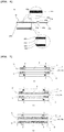
- FIG. 2 is a perspective diagram of the frame 10 according to an embodiment of the present disclosure.
- the frame 10 may include the sensing part 110 and the body part 120.
- the sensing part 110 may have the sensing hole 111a for connecting with the terminal formed therein, and may be connected with the body part 120 through the connection part 112 according to the spacing distance with the terminal. That is, the sensing part 110 is connected with one side of the connection part 112 and the other side of the connection part 112 is connected with the body part 120, such that the sensing part 110 and the body part 120 may be electrically connected.
- the curved part 113 may be formed on the connection part 112 to structurally provide the elasticity to the frame 10.
- the curved part 113 may be a structure in which the vibration may be generated by the vehicle during driving and the resistance against the above may be enhanced.
- the curved part 113 may also be formed in the body part 120.
- the curved part 123 of the body part 120 may also be the same reason as described above.
- the thickness of the frame 10 may be 0.5mm. This thickness may be made thicker by forming enhanced parts (213a, 220a in FIG. 3 ), and accordingly, may be determined considering the thickness of the enhanced part when manufacturing the frame 10. That is, if the enhanced parts (213a, 220a in FIG. 3 ) are not formed or are formed only on one side thereof, the thickness of the frame 10 may be determined to be 1mm to 1.5mm during the manufacturing thereof.
- the body part 120 may have a valley 121 and a ridge 122 by the curved part 123.
- a hollow hole 121a may be formed in a portion of the valley 121, the ridge 122, and the curved part 123.
- the illustrated example is an example in which the hollow hole 121a has been formed in the valley 121, but may be formed even in the ridge, and it is possible to expect the effects such as the heat dissipation and electrical low resistance property through the hollow hole 121a.
- the exposed area in the air of the body part 120 may be increased by the curved part 123, thereby further increasing the heat dissipation effect.
- this effect may also correspond to the curved part 113 formed on the connection part 112.
- heat may be dissipated through the exposed surface if the surface exposed to the outside is formed even after a primary enhancing injection material (222a in FIG. 3 ) and a secondary enhancing injection material (223a in FIG. 3 ) have been positioned in the frame 10.
- the bus bar 20 may further include enhanced parts 213a, 220a in the frame 10.
- the thickness of the bus bar 20 may be increased overall or locally.
- This example is an example in which the enhancing injection materials 222a, 223a have been injected into the curved part 213 and a portion of the body part 220, and the current passing cross-sectional areas of the body part 220 and the curved part 213 are increased by the enhancing injection materials 222a, 223a, thereby reducing the electrical resistance to enhance the electrical conductivity and to enhance the durability by the vibration.
- the enhanced parts 213a, 221a may be selectively formed by a primary injection molding and a secondary injection molding, for example, the enhancing injection materials 222a, 223a may be injected into the curved part 213 to form the enhanced part 213a, and the enhanced part 220a may be formed on one end of the body part 120, which may be connected with a separate member.
- the enhanced parts 213a, 220a may be selectively formed by the primary injection molding and the secondary injection molding, the enhanced part may be formed even in any portion not described in this example as many as possible.
- the enhanced parts 213a, 220a may be enhanced twice on the bottom surface and the top surface of the frame 10. If the primary enhancing injection material 222a is injected into the bottom surface of the body part 120 of the frame 10 to be coupled with the frame 10, the secondary enhancing injection material 223a is injected into the top surface of the body part 120 to be coupled with the frame 10. As described above, the thickness of the bus bar at this time may be 1mm to 1.5mm. Further, the primary enhancing injection material 222a and the secondary enhancing injection material 223a may be different materials from each other, and at least one material may be resin.
- FIG. 4 is a diagram illustrating the frame 30 and a partial structure of the mold 1 according to another embodiment of the present disclosure
- FIG. 4A is a perspective diagram of the frame 30 according to another embodiment of the present disclosure
- FIG. 4B is a perspective diagram of a protrusion 2 formed in the mold according to an embodiment of the present disclosure.
- the frame 30 may further include the guide 330 in the frame 10 described above.
- the guide 330 is a structure for fixing the frame 30 not to be moved when the enhancing injection material is supplied in the mold 1 during the primary injection molding and the secondary injection molding, and may be positioned in the mold 1 during the primary injection molding and the secondary injection molding.
- the guide 330 may allow a portion of the frame 30 positioned inside the mold 1 to be fixed without being moved.
- the frame 30 having a structure integrally formed with the guide 330 may be connected by a notch 330a in the mold.
- the notch 330a may separate the guide 330 from the frame 30 by a method such as the cutting after the secondary injection molding. That is, the notch 330a may allow the frame 30 to be fixed without being moved in the mold 1, and when the secondary injection molding is completed, the connection area is preferably formed to be small so that the guide 330 is easily separated.
- a pinhole 331 may be formed in the guide 330 for the fixing.
- the guide 331 may be fixed to fix the frame 30 and the pinhole 331 may be coupled with and fixed to a pin formed in the mold. Accordingly, two pinholes 331 may be formed.
- it is a structure for the fixing, which is limited to a circular case, and in the case of a prismatic hole such as a square, one or more holes may also be formed.
- the protrusion 2 is formed in the mold 1, and a groove corresponding to the protrusion 2 may be formed in the frame 10.
- the protrusion 2 is a structure for pressing the frame 10, and although the protrusion 2 is not formed to correspond to the groove, the protrusion 2 may contact the surface of the frame 10 to support the frame 10.
- the protrusion 2 may be protruded from the mold 1, and may be disposed with the mold 1 with an elastic body 3 interposed therebetween. That is, in order to fix the frame 10, the protrusion 2 may press the frame 10 by the elastic body 3 in a direction protruding from the mold 1.
- FIG. 5 is a diagram illustrating bus bars 40, 50, 60 according to other embodiments of the present disclosure
- FIG. 5A is a diagram illustrating the bus bar 40 of a " " shape
- FIG. 5B is a diagram illustrating the bus bar 50 of a " “ shape
- FIG. 5C is a diagram illustrating the bus bar 60 of a "2" shape. This example is intended to disclose various examples in terms of shapes of the bus bars 40, 50, 60.
- the bus bars 40, 50, 60 have sensing parts 410, 510, 610 positioned on both ends thereof, respectively, and have body parts 420, 520, 620 positioned between the respective sensing parts 410, 510, 610, the bending of the body parts 420, 520, 620 may be formed variously.
- the bus bars 20, 40, 50, 60 manufactured by the insert injection may be made of a nonferrous metal, and for example, the nonferrous metal may be aluminum, copper, or the like. Further, the manufactured bus bars 20, 40, 50, 60 may be formed so that the thicknesses of the body part 200 and the connection part 100 become different by the enhanced parts (213a, 221a in FIG. 3 ) through the enhancement by the enhancing injection materials 222a, 223a. The elasticity may be determined by the difference.
- the bus bars 20, 40, 50, 60 in which the injecting the primary enhancing injection material (operation S2) and the injecting the secondary enhancing injection material (operation S3) have been performed in the frame 10 by the enhancing injection materials 222a, 223a, may have the sensing parts 210, 410, 510, 610 surface-treated by nickel, tin, or the like.
- the sensing parts 210, 410, 510, 610 may be configured by forming a plating layer including at least any one of nickel, gold, copper, and tin.
- the frames 10, 30 may have an irregularity part formed on the outer surface contacting the frame 1.
- the irregularity part is non-uniform and rough, includes a protrusion or uneven shape, and includes one or more of a hole, a spike, and a drawing.
- the enhancing injection materials 222a, 223a may be injected into the irregularity part side to further increase the coupling force between the frames 10, 30 and the enhancing injection materials 222a, 223a after the curing.
- the body parts 120, 320 which may be heat-generated by the flow of the current, have the injection of the enhancing injection materials 222a, 223a during the secondary injection molding asymmetrically performed on one surface and the other surface thereof, such that the enhanced part for the enhancement may be formed only on one surface side of the body parts 120, 320. Accordingly, the other surface side of the body parts 120, 320 where the enhanced part is not formed may be exposed to the outside, which may be advantageous to dissipate the heat due to the heat generation.
- the enhanced part formed by the enhancing injection material may also be positioned at a position except for the sensing parts 110, 210, 310, 410, 510, 610.
- the cross-sectional area and the outer surface area of the flow direction of the current of the portion thickened by the enhancing injection material may be increased in the bus bars 20, 40, 50, 60, thereby enhancing the electrical conductivity and the heat dissipation property.
- the sensing parts 110, 210, 310, 410, 510, 610 may be plated, and the plating may include at least one of gold, silver, nickel, zinc, tin, or the like and the electrical conduction property may be further enhanced by the plating.
- FIG. 6 is a diagram illustrating a shape of a stacked bus bar 70 according to another embodiment of the present disclosure.
- FIG. 6 exemplarily illustrates a case where two frames have been stacked, but a case where three or more frames are stacked may also be applied to the following description.
- FIG. 6 it may be an embodiment in which the insert injection is performed in a state where a plurality of frames have been stacked.
- body parts (42; 421a, 421b) and respective connection parts 412a, 412b of each frame may be stacked and the stacked frame may be inserted into the mold and injection-molded.
- the primary enhancing injection material 222a and the secondary enhancing injection material 223a to be injected during the injection molding may be injected into the lower surface and the upper surface of the stacked frame, respectively.
- the primary enhancing injection material 222a may be supplied to the body parts (42; 421b) positioned at the lower side thereof
- the secondary enhancing injection material 223a may be supplied to the body parts (42; 421a) positioned at the upper side thereof.
- the enhancing injection materials 222a, 223a may be injected into a portion of the exposed areas of the stacked frame or the entire exposed area thereof.
- the enhancing injection materials 222a, 223a When the enhancing injection materials 222a, 223a are injected into the portion, for example, the enhancing injection materials 222a, 223a may be supplied to a planar portion.
- the planar portion may include valleys 421a, 421b, a ridge 422a, and the like except for the curved parts 423a, 413a, 413b.
- a portion into which the enhancing injection materials 222a, 223a are injected may be performed for the purpose of enhancing the durability, or the like, as in the above-described embodiment.
- the area into which the enhancing injection materials 222a, 223a are injected may further include the side surface of the stacked frame.
- the coupling between the respective frames may be made by injecting it by stacking a plurality of frames and then injecting the enhancing injection materials 222a, 223a into the surface including the side surface thereof.
- the coupling state contacting each other by a welding including a laser welding and an adhesive agent between the respective frames may be maintained.
- the stacked frame may coupled by being pressed to each other by a pressing means such as the bending so that the enhancing injection materials 222a, 223a are not injected between the respective frames.
- FIG. 7A to 7C are diagrams illustrating the injection of the enhancing injection material according to embodiments of the present disclosure, and referring to FIGS. 7A to 7C , the enhancing injection material may be injected after the frames 10, 30 have been mounted in the mold 1.
- the mounting of the frames 10, 30 in the mold 1 means the mounting having a fixing force of the degree that the frames 10, 30 may maintain their positions in the mold 1 against the pressure generated when the enhancing injection material is injected.
- the mounting may be performed by one or more protrusions 2 formed in the mold 1.
- the protrusion 2 may be coupled by the mold 1 and the elastic body 3. Accordingly, the protrusion 2 may receive the elasticity from the elastic body 3 in a direction of supporting the frames 10, 30 to press, mount, and fix the frames 10, 30 with a predetermined force.
- the frames 10, 30 supported and fixed by the protrusion 2 are introduced into a cavity 4 in the mold 1 by the enhancing injection material, and the introduced enhancing injection material may be provided up to a position adjacent to the protrusion 2.
- the protrusion 2 may be a pin or cylinder shape, the enhancing injection material may be provided up to the periphery of the protrusion 2. If the projection 2 is pressed by the pressure of the enhancing injection material as in FIG. 7B , the protrusion 2 may be introduced into the mold 1.
- the protrusion 2 may have an inclined surface formed on the end portion in the pressing direction.
- the inclined surface is formed at an angle except for a direction parallel or perpendicular to a direction (D) of injecting the enhancing injection material, and may be formed in a direction of reducing the cross-sectional area as the protrusion 2 extends in the pressing direction. Accordingly, the enhancing injection material presses the inclined surface to introduce the protrusion 2 into the mold 1, and the positions of the frames 10, 30 may be maintained by the enhancing injection material.
- the frame may have the enhanced parts 213a, 221a formed at the position where the enhancing injection material has been injected.
- the enhancing injection material has been injected into the upper and lower surfaces with respect to the frames 10, 30 in this embodiment, the cavity 4 is formed only on one side surface according to the shape of the mold 1 to inject the enhancing injection material into the cavity 4 side.
- the position where the enhanced parts 213a, 221a are formed in the frames 10, 30 may be optional, and if the enhanced parts 213a, 221a are formed on the upper surface and the lower surface of the frames 10, 30, they may also be manufactured by injecting the primary and secondary enhancing injection materials, and may also be manufactured by injecting the enhancing injection material once.
Landscapes
- Engineering & Computer Science (AREA)
- Manufacturing & Machinery (AREA)
- Mechanical Engineering (AREA)
- Chemical & Material Sciences (AREA)
- Chemical Kinetics & Catalysis (AREA)
- Electrochemistry (AREA)
- General Chemical & Material Sciences (AREA)
- Injection Moulding Of Plastics Or The Like (AREA)
Abstract
Description
- The present disclosure relates to a method for manufacturing a bus bar and the bus bar manufactured by the same.
- In general, as a method for manufacturing a bus bar, there are a method for manufacturing a bus bar by manufacturing a body part and a sensing part separately and bonding them to each other and a method for manufacturing the bus bar by integrating them. Among them, the method for manufacturing the bus bar by manufacturing the sensing part and the body part separately and bonding them by welding or the like additionally requires a manufacturing process of bonding, and causes an increase in the manufacturing process and the cost due to degradation of durability of a bonded part and the degradation of durability of the bonded part. On the other hand, in order to solve this problem, the method for manufacturing the bus bar by integrating them may omit the bonding process, and may not occur the breakage of the degradation of durability at the bonded part. However, relaxation and contraction may occur due to an impact applied to the bus bar, and the relaxation and the contraction may cause a short circuit between the sensing part and the body part.
- [Patent Document 1] Korean Patent Laid-Open Publication No.
10-2014-0146232 (December 24, 2014 - In order to solve a problem due to a short circuit of a connection part caused by relaxation and contraction of a body part and a sensing part by the conventional bus bar for an electric vehicle using an integrated bus bar of the body part and the sensing part, an object of an embodiment of the present disclosure is to provide a method for manufacturing an integrated bus bar of a body part and a sensing part and then manufacturing it so that the body part and the sensing part of the bus bar are positioned in the thickness of an injection-molded product by performing a primary or primary and secondary insert injection molding for the integrated bus bar, and a method for manufacturing a bus bar that secures durability of the bus bar by injection-molding only the sensing part.
- In order to solve a problem due to a short circuit of a connection part caused by relaxation and contraction of a body part and a sensing part by the conventional bus bar for an electric vehicle using an integrated bus bar of the body part and the sensing part, another object of an embodiment of the present disclosure is to provide a method for manufacturing an integrated bus bar of a body part and a sensing part and then manufacturing it so that the body part and the sensing part of the bus bar are positioned in the thickness of an injection-molded product by performing a primary or primary and secondary insert injection molding for the integrated bus bar, and a bus bar that secures durability of the bus bar by injection-molding only the sensing part.
- In order to solve a problem that may cause degradation of the price competitiveness and a quality problem due to the difficulty in confirming the presence or absence of the bonding due to many manufacturing processes in the process of manufacturing a body part and a sensing part with a heterogeneous material, respectively to bond them through ultrasonic, laser, or the like, still another object of an embodiment of the present disclosure is to provide a method for manufacturing an integrated bus bar of a body part and a sensing part and then manufacturing it so that the body part and the sensing part of the bus bar are positioned in the thickness of an injection-molded product by performing a primary or primary and secondary insert injection molding for the integrated bus bar, and a method for manufacturing a bus bar that secures durability of the bus bar by injection-molding only the sensing part.
- In order to solve a problem that may cause degradation of the price competitiveness and a quality problem due to the difficulty in confirming the presence or absence of the bonding due to many manufacturing processes in the process of manufacturing a body part and a sensing part with a heterogeneous material, respectively to bond them through ultrasonic, laser, or the like, still another object of an embodiment of the present disclosure is to provide a method for manufacturing an integrated bus bar of a body part and a sensing part and then manufacturing it so that the body part and the sensing part of the bus bar are positioned in the thickness of an injection-molded product by performing a primary or primary and secondary insert injection molding for the integrated bus bar, and a bus bar that secures durability of the bus bar by injection-molding only the sensing part.
- According to an embodiment of the present disclosure, provided is a method for manufacturing a bus bar in which a frame including a sensing part and a body part connected to the sensing part is prepared, the frame is inserted into and fixed to an injection molding mold, and an enhanced part is formed in the frame in order to improve the degree of one or more of the strength and the insulation at one or more positions of a position where fatigue is concentrated and a position capable of electrical conduction by an enhancing injection material injected into the injection molding mold.
- Further, the insertion and the fixing may be performed by a protrusion in the injection molding mold, and the protrusion may be introduced into the injection molding mold by the supply pressure of the enhancing injection material.
- Further, the enhancing injection material may be injected into the injection molding mold once to form the enhanced part in the frame.
- Further, the fatigue may occur in a direction in which the frame is repeatedly bent.
- Further, the fatigue may occur at one or more positions of the body part and the sensing part.
- Further, the frame may further include a connection part connecting between the sensing part and the body part.
- Further, the fatigue may occur at one or more positions of the body part, the sensing part, and the connection part.
- The enhancing injection material may include a primary enhancing injection material and a secondary enhancing injection material injected sequentially, and one surface of the frame may be enhanced through a primary injection molding by injecting the primary enhancing injection material therein, and the other surface of the frame may be enhanced through a secondary injection molding by injecting the secondary enhancing injection material therein.
- Further, the fatigue may occur in a direction in which the frame is repeatedly bent.
- Further, the fatigue may occur at one or more positions of the body part and the sensing part.
- Further, the frame may further include a connection part connecting between the sensing part and the body part.
- Further, the fatigue may occur at one or more positions of the body part, the sensing part, and the connection part.
- Further, a nonferrous metal may be aluminum or copper.
- Further, the frame may further include a connection part connecting between the sensing part and the body part, and one or more of the primary injection molding and the secondary injection molding may be performed on the connection part.
- Further, the frame may further include a connection part connecting between the sensing part and the body part, and the connection part may be prepared to have elasticity.
- Further, elasticity may be provided by a curved part prepared on the connection part.
- Further, the connection part may be surface-treated by one or more among nickel, tin, gold, silver, and zinc.
- Further, the body part may include a through hole to enhance a heat dissipation property and a low resistance property.
- Further, the through hole may be a rectangular or circular hole.
- Further, the frame may be adhered to an upper mold by a protrusion formed in the injection molding mold so that an insert position is fixed during the primary injection molding and the secondary injection molding.
- Further, the frame may include an irregularity part enhancing the adhesion with the primary enhancing injection material and the secondary enhancing injection material.
- Further, the irregularity part may include at least one among a hole, a spike, and a drawing, and may be formed on one or more contact surfaces of the frame and the primary enhancing injection material or the secondary enhancing injection material.
- Further, the primary enhancing injection material and the secondary enhancing injection material may be different materials from each other.
- Further, one or more of the primary enhancing injection material and the secondary enhancing injection material may include resin.
- Further, at least partial portion in which a wire may be coupled to the body part may be blocked from being injected by the primary enhancing injection material and the secondary enhancing injection material, respectively, during the primary injection molding and the secondary injection molding.
- Further, the frame may include a carrier configured to fix the frame to the injection molding mold during the primary injection molding and the secondary injection molding.
- Further, the frame may be manufactured in a state where the frame and a guide have been connected, and the guide and the frame may be connected by a notch to separate the frame and the guide with respect to the notch after the secondary injection molding.
- Further, the sensing part may be plated by one among gold, silver, nickel, tin, and zinc.
- Provided is a bus bar including a sensing part, a body part connected to the sensing part, and an enhanced part enhancing one or more of the strength and the insulation of the body part, and the enhanced part is formed at one side of the body part, and the enhanced part is made of one or more materials.
- Further, the bus bar may further include a connection part connecting between the sensing part and the body part.
- Provided is a bus bar including a sensing part, a connection part having one side coupled to the sensing part, a body part coupled to the other side of the connection part, and an enhanced part formed at one side in the body part and the connection part, and enhancing one or more of the strength and the insulation at one or more positions of the connection part and the body part.
- Further, the enhanced part may include a primary enhancing injection material and a secondary enhancing injection material, and one or more of the primary enhancing injection material and the secondary enhancing injection material may be resin.
- Provided is a bus bar including a sensing part, a connection part having one side coupled to the sensing part, a body part coupled to the other side of the connection part, and an enhanced part enhancing one or more of the strength and the insulation in the connection part and the body part, and the body part is prepared in plural and stacked on each other, and the enhanced part is formed on a portion of an exposed surface in a state where the body part has been stacked on each other.
- An embodiment of the present disclosure may provide the bus bar, which may secure the thickness and tensile strength of the body and secure the elastic force of the sensing part, thereby preventing the short circuit of the connection part due to relaxation and contraction.
- An embodiment of the present disclosure may provide a method for manufacturing the bus bar, which may not separate the manufacturing process, thereby preventing degradation of the price competitiveness.
-
-
FIG. 1 is a flowchart illustrating a process of manufacturing a bus bar according to an embodiment of the present disclosure. -
FIG. 2 is a perspective diagram of a frame according to an embodiment of the present disclosure. -
FIG. 3 is a perspective diagram of a bus bar according to embodiments of the present disclosure. -
FIG. 4A is a perspective diagram of a frame according to another embodiment of the present disclosure, andFIG. 4B is a diagram of a protrusion formed in a mold according to an embodiment of the present disclosure. -
FIG. 5 is a diagram illustrating a shape of a bus bar according to other embodiments of the present disclosure. -
FIG. 6 is a diagram illustrating a shape of a stacked bus bar according to another embodiment of the present disclosure. -
FIGS. 7A to 7C are diagrams illustrating the injection of an enhancing injection material according to embodiments of the present disclosure. - Hereinafter, a specific embodiment of the present disclosure will be described with reference to the accompanying drawings. However, this is merely for illustrative and the present disclosure is not limited thereto.
- In the following description of the present disclosure, if it is determined that a specific description of the known technology related to the present disclosure unnecessarily obscures the gist of the present disclosure, a detailed description thereof will be omitted. Further, terms to be described later are terms defined considering the function in the present disclosure, which may be changed according to the intent, custom, or the like of a user or an operator. Accordingly, its definition should be made based on the contents throughout the present specification.
- The technical spirit of the present disclosure is determined by the claims, and the following embodiment is merely a means for efficiently explaining the technical spirit of the present disclosure to those skilled in the art to which the present disclosure pertains.
- Further, hereinafter, a method for enhancing a frame (10 in
FIG. 2 ) and a bus bar (20 inFIG. 3 ) manufactured by the method will be described later. Here, the enhancement may be a purpose of enhancing the strength against an external impact to be applied to the frame (10 inFIG. 2 ) and a purpose of adding, maintaining, and enhancing the insulation from the outside. For example, if the manufactured bus bar (20 inFIG. 3 ) is connected with a battery of a vehicle, thebus bar 20 may be affected by the vibration generated during driving of the vehicle. At this time, the bending, or the like may be affected by the vibration and pressure delivered from a surrounding structure, and here, it may be said to be a kind of enhancing process of enhancing the resistance of the bending. Accordingly, the most vulnerable point due to the bending may be formed as an enhanced part in the manufacturing process in order to enhance the strength from the bending that causes fatigue. A position of the enhanced part may be one or more positions of the body parts (420, 520, 620 inFIG. 5 ) and the sensing parts (410, 510, 610 inFIG. 5 ), and may be formed on a connection part (112 inFIG. 2 ) if the frame (10 inFIG. 2 ) includes the connection part (112 inFIG. 2 ). For example, the enhanced part may also be formed on the connection part that is formed to be relatively narrow in width and vulnerable to the bending. Of course, a curved part (113 inFIG. 2 ) may be formed on the connection part (112 inFIG. 2 ) and may also be structurally formed to have the elasticity at the point where the bending is applied. - Further, for the purpose of adding, maintaining, and enhancing the insulation from the outside, it is possible to serve as a coating. That is, it is possible to conceal an area exposed from the outside, thereby preventing an electrical accident such as a short that may be caused by the inevitable contact with the surrounding structure. It is possible to prevent the electrical accident caused by the contact with the moisture as well as the surrounding structure in advance. Accordingly, it is possible to inject a material capable of suppressing the electrical conductivity during the injection without injecting an enhancing injection material that may serve as a conductor after the curing during the injection. For example, it is possible to inject the enhancing injection material containing a resin material during the injection, thereby adding, maintaining, and enhancing the insulation.
- Hereinafter, an embodiment in which an enhancing injection process is performed in plural times and an embodiment in which an enhancing injection process is performed once in order to form the enhanced part will be described later. An embodiment in which primary and secondary injection moldings are performed will be described with reference to
FIGS. 1 to 6 , and a process of forming the enhanced part through a one-time injection molding process will be described with reference toFIG. 7 . Further, when the description is made with reference toFIG. 7 , different points therebetween will be mainly described in comparison with the contents described with reference toFIGS. 1 to 6 . -
FIG. 1 is a flowchart illustrating a process of manufacturing the bus bar (20 inFIG. 2 ) according to an embodiment of the present disclosure. - Referring to
FIG. 1 , the bus bar (20 inFIG. 2 ) may be manufactured in the order of manufacturing a frame (operation S1), injecting a primary enhancing injection material (operation S2), injecting a secondary enhancing injection material (operation S3), and detaching (operation S4). Specifically, the manufacturing the frame (operation S1) may manufacture the frame (10 inFIG. 2 ) including a sensing part (110 inFIG. 2 ) and a body part (120 inFIG. 2 ). The frame (10 inFIG. 2 ) manufactured by a method such as a press may be manufactured as the bus bar (20 inFIG. 3 ) while being coupled through the enhancing injection material and the injection. The frame (10 inFIG. 2 ) may be manufactured by including shapes of acurved part 113, asensing hole 111a, and the like in the sensing part (110 inFIG. 2 ) and shapes of acurved part 123, ahollow hole 121a, and the like in thebody part 120. That is, a shape that is the base of the bus bar (20 inFIG. 3 ) may be prepared. Here, thesensing part 110 and thebody part 120 may be integrally formed, and do not include a separate bonding process. Accordingly, it is possible to prevent degradation of the durability due to the coupling structure. - That is, it is possible to enhance the mechanical performance by being manufactured integrally. Here, the mechanical performance may mean performance of maintaining a coupling force against the vibration, or the like, performance capable of resisting against the breakage that may occur from an external force, or the like. Such performance may be advantageous because of having a higher resistance than that of the bus bar manufactured by the coupling between two members against the vibration of the vehicle, or the like if the bus bar (20 in
FIG. 3 ) of an embodiment of the present disclosure is included for example, in a component of the vehicle, or the like. Of course, as described above, it is also possible to expect the enhancement in the insulation. Since the effect that may be expected from the enhanced part is optional, the enhancing injection material may be determined as a metal material when the rigidity is prioritized to the insulation by those skilled in the art, and determined as a material such as a resin material when the insulation is prioritized to the rigidity. Accordingly, a material of the enhancing injection material is optional, and it is possible to adjust the specific gravity of the insulation and the rigidity by fusing a plurality of materials. Furthermore, it is also possible to provide the elasticity to the enhanced part. - Further, the frame manufactured in the manufacturing the frame (operation S1) may be, for example, 5mm. The 5mm is an example of the thickness corresponding to 50% of the thickness of the bus bar manufactured without undergoing the process of being enhanced through the injection, and the present disclosure is not limited to 5mm. Hereinafter, a process of manufacturing a bus bar will be described by taking the frame manufactured to the thickness of 5mm as an example.
- The frame (10 in
FIG. 2 ) manufactured through the manufacturing the frame (operation S1) may enhance a portion having a weak durability, that is, a portion where a stress may be concentrated by an external force. For example, an enhancing injection material may be injected for the purpose of enhancing the frame (10 inFIG. 2 ). Accordingly, in order to inject it by injecting the enhancing injection material, the frame (10 inFIG. 2 ) may be disposed in a primary injection molding mold and the injecting the primary enhancing injection material (operation S2) may be performed. The primary enhancing injection material may be injected, for example, into one surface of the frame (10 inFIG. 2 ). Here, one surface of the frame (10 inFIG. 2 ) may be the bottom surface of the frame (10 inFIG. 2 ), and may be a portion of the bottom surface or the entire bottom surface. - Further, thereafter, the mold may be rearranged to perform the injecting the secondary enhancing injection material (operation S3). If the enhancing injection material has been injected into the bottom surface in the injecting the primary enhancing injection material (operation S2), only an upper mold may be rearranged and the secondary enhancing injection material may be injected therein. In this case, the secondary enhancing injection material may be injected (operation S3) into the other surface of the frame (10 in
FIG. 2 ). Here, the other surface may be the upper surface of the frame (10 inFIG. 2 ), and may be a portion of the upper surface or the entire upper surface. - However, in the injecting the primary enhancing injection material (operation S2) and the injecting the secondary enhancing injection material (operation S3), the sensing part (110 in
FIG. 2 ), as a terminal capable of the electrical conduction, may be blocked from the injection of the enhancing injection material. Accordingly, the sensing part (110 inFIG. 2 ) may be exposed even after being manufactured as the bus bar (20 inFIG. 3 ). Here, the frame (10 inFIG. 2 ) may be made of a nonferrous metal, for example, aluminum or copper. Further, the enhancing injection materials injected primarily and secondarily may contain at least resin. Accordingly, if the enhancing injection material is not blocked for the sensing part (110 inFIG. 2 ), the electrical conduction through the sensing part (110 inFIG. 2 ) may be impossible, such that the enhancing injection material may be blocked. Furthermore, the sensing part (110 inFIG. 2 ) may be plated with one material of gold, silver, nickel, tin, and zinc. - Meanwhile, in the mold disposed for injecting the primary enhancing injection material and the secondary enhancing injection material, the frame (10 in
FIG. 2 ) has been fixed in the mold and then the enhancing injection material may be injected (operations S2, S3), and a fixing means may be formed to prevent the frame (10 inFIG. 2 ) from being moved in the mold by the injected enhancing injection material. - One or more of a hole, a spike, and a drawing may be formed in the frame, formed on the contact surfaces where the primary enhancing injection material, the secondary enhancing injection material, and the frame (10 in
FIG. 2 ) may contact each other, and formed on one or more contact surfaces among the contact surfaces, thereby enhancing the adhesion between the frame (10 inFIG. 2 ) and one or more of the primary enhancing injection material and the secondary enhancing injection material. - Meanwhile, the injected enhancing injection material may be fixed to the frame (10 in
FIG. 2 ) to enhance a low durability portion of the frame (10 inFIG. 2 ). Further, this enhancing injection material may be injected for the purpose of enhancing the durability, but may also be injected to form a heat dissipation surface. For example, if one surface of thebody part 120 has been disposed in the mold to be injected into only some areas when being injected by the enhancing injection material, an area where the enhancing injection material is not supplied may be exposed to the outside. Since the exposed surface is exposed even after the bus bar (20 inFIG. 3 ) has been manufactured, it may be a surface where the heat generated during the flow of the current may be dissipated. For example, the heat dissipating surface is one surface of thebody part 120, and as the exposed area is wider, the heat dissipation is better. - Subsequently, the detaching the mold (operation S4) may separate it from a guide (330 in
FIG. 4 ) in the case of manufacturing by further including the guide (330 inFIG. 4 ) in the frame (10 inFIG. 2 ) in the injecting the enhancing injection materials (operations S2, S3). This will be described later in detail with reference toFIG. 4 . -
FIG. 2 is a perspective diagram of theframe 10 according to an embodiment of the present disclosure. - Referring to
FIG. 2 , theframe 10 may include thesensing part 110 and thebody part 120. Here, thesensing part 110 may have thesensing hole 111a for connecting with the terminal formed therein, and may be connected with thebody part 120 through theconnection part 112 according to the spacing distance with the terminal. That is, thesensing part 110 is connected with one side of theconnection part 112 and the other side of theconnection part 112 is connected with thebody part 120, such that thesensing part 110 and thebody part 120 may be electrically connected. In this embodiment, thecurved part 113 may be formed on theconnection part 112 to structurally provide the elasticity to theframe 10. As described above, if thecurved part 113 is included in a component of the vehicle, thecurved part 113 may be a structure in which the vibration may be generated by the vehicle during driving and the resistance against the above may be enhanced. Thecurved part 113 may also be formed in thebody part 120. Thecurved part 123 of thebody part 120 may also be the same reason as described above. - As described above, the thickness of the
frame 10 may be 0.5mm. This thickness may be made thicker by forming enhanced parts (213a, 220a inFIG. 3 ), and accordingly, may be determined considering the thickness of the enhanced part when manufacturing theframe 10. That is, if the enhanced parts (213a, 220a inFIG. 3 ) are not formed or are formed only on one side thereof, the thickness of theframe 10 may be determined to be 1mm to 1.5mm during the manufacturing thereof. - Meanwhile, the
body part 120 may have avalley 121 and aridge 122 by thecurved part 123. Ahollow hole 121a may be formed in a portion of thevalley 121, theridge 122, and thecurved part 123. The illustrated example is an example in which thehollow hole 121a has been formed in thevalley 121, but may be formed even in the ridge, and it is possible to expect the effects such as the heat dissipation and electrical low resistance property through thehollow hole 121a. - In particular, regarding the heat dissipation, the exposed area in the air of the
body part 120 may be increased by thecurved part 123, thereby further increasing the heat dissipation effect. Of course, this effect may also correspond to thecurved part 113 formed on theconnection part 112. Further, heat may be dissipated through the exposed surface if the surface exposed to the outside is formed even after a primary enhancing injection material (222a inFIG. 3 ) and a secondary enhancing injection material (223a inFIG. 3 ) have been positioned in theframe 10. - Referring to
FIGS. 3A and 3B , as thebus bar 20 manufactured by supplying the enhancinginjection materials frame 10 inFIG. 2 , thebus bar 20 may further includeenhanced parts frame 10. By forming theenhanced parts bus bar 20 may be increased overall or locally. This example is an example in which the enhancinginjection materials curved part 213 and a portion of thebody part 220, and the current passing cross-sectional areas of thebody part 220 and thecurved part 213 are increased by the enhancinginjection materials - As described above, since the
enhanced parts injection materials curved part 213 to form theenhanced part 213a, and theenhanced part 220a may be formed on one end of thebody part 120, which may be connected with a separate member. As described above, since theenhanced parts - Meanwhile, the
enhanced parts frame 10. If the primary enhancinginjection material 222a is injected into the bottom surface of thebody part 120 of theframe 10 to be coupled with theframe 10, the secondary enhancinginjection material 223a is injected into the top surface of thebody part 120 to be coupled with theframe 10. As described above, the thickness of the bus bar at this time may be 1mm to 1.5mm. Further, the primary enhancinginjection material 222a and the secondary enhancinginjection material 223a may be different materials from each other, and at least one material may be resin. -
FIG. 4 is a diagram illustrating theframe 30 and a partial structure of themold 1 according to another embodiment of the present disclosure; andFIG. 4A is a perspective diagram of theframe 30 according to another embodiment of the present disclosure andFIG. 4B is a perspective diagram of aprotrusion 2 formed in the mold according to an embodiment of the present disclosure. - Referring to
FIG. 4A , theframe 30 may further include theguide 330 in theframe 10 described above. Theguide 330 is a structure for fixing theframe 30 not to be moved when the enhancing injection material is supplied in themold 1 during the primary injection molding and the secondary injection molding, and may be positioned in themold 1 during the primary injection molding and the secondary injection molding. For example, theguide 330 may allow a portion of theframe 30 positioned inside themold 1 to be fixed without being moved. - The
frame 30 having a structure integrally formed with theguide 330 may be connected by anotch 330a in the mold. Thenotch 330a may separate theguide 330 from theframe 30 by a method such as the cutting after the secondary injection molding. That is, thenotch 330a may allow theframe 30 to be fixed without being moved in themold 1, and when the secondary injection molding is completed, the connection area is preferably formed to be small so that theguide 330 is easily separated. - Further, a
pinhole 331 may be formed in theguide 330 for the fixing. Theguide 331 may be fixed to fix theframe 30 and thepinhole 331 may be coupled with and fixed to a pin formed in the mold. Accordingly, twopinholes 331 may be formed. Of course, it is a structure for the fixing, which is limited to a circular case, and in the case of a prismatic hole such as a square, one or more holes may also be formed. - Referring to
FIG. 4B , as another fixing method of theframe 10 in themold 1, theprotrusion 2 is formed in themold 1, and a groove corresponding to theprotrusion 2 may be formed in theframe 10. Theprotrusion 2 is a structure for pressing theframe 10, and although theprotrusion 2 is not formed to correspond to the groove, theprotrusion 2 may contact the surface of theframe 10 to support theframe 10. As one embodiment, theprotrusion 2 may be protruded from themold 1, and may be disposed with themold 1 with anelastic body 3 interposed therebetween. That is, in order to fix theframe 10, theprotrusion 2 may press theframe 10 by theelastic body 3 in a direction protruding from themold 1. -
FIG. 5 is a diagram illustrating bus bars 40, 50, 60 according to other embodiments of the present disclosure; andFIG. 5A is a diagram illustrating thebus bar 40 of a "" shape,
FIG. 5B is a diagram illustrating thebus bar 50 of a "" shape, and
FIG. 5C is a diagram illustrating thebus bar 60 of a "2" shape. This example is intended to disclose various examples in terms of shapes of the bus bars 40, 50, 60. - Referring to
FIG. 6 , as an example in which the bus bars 40, 50, 60 havesensing parts body parts respective sensing parts body parts - Furthermore, here, the bus bars 20, 40, 50, 60 manufactured by the insert injection may be made of a nonferrous metal, and for example, the nonferrous metal may be aluminum, copper, or the like. Further, the manufactured bus bars 20, 40, 50, 60 may be formed so that the thicknesses of the body part 200 and the connection part 100 become different by the enhanced parts (213a, 221a in
FIG. 3 ) through the enhancement by the enhancinginjection materials - Further, the bus bars 20, 40, 50, 60, in which the injecting the primary enhancing injection material (operation S2) and the injecting the secondary enhancing injection material (operation S3) have been performed in the
frame 10 by the enhancinginjection materials sensing parts sensing parts - Further, in order to enhance the adhesion by the enhancing
injection materials frames frame 1. The irregularity part is non-uniform and rough, includes a protrusion or uneven shape, and includes one or more of a hole, a spike, and a drawing. The enhancinginjection materials frames injection materials - Further, the
body parts injection materials body parts body parts - Further, the enhanced part formed by the enhancing injection material may also be positioned at a position except for the
sensing parts sensing parts -
FIG. 6 is a diagram illustrating a shape of a stackedbus bar 70 according to another embodiment of the present disclosure.FIG. 6 exemplarily illustrates a case where two frames have been stacked, but a case where three or more frames are stacked may also be applied to the following description. - Referring to
FIG. 6 , it may be an embodiment in which the insert injection is performed in a state where a plurality of frames have been stacked. For example, as a form of stacking a plurality of frames, body parts (42; 421a, 421b) andrespective connection parts - Here, the primary enhancing
injection material 222a and the secondary enhancinginjection material 223a to be injected during the injection molding may be injected into the lower surface and the upper surface of the stacked frame, respectively. In this example in which two frames have been stacked, the primary enhancinginjection material 222a may be supplied to the body parts (42; 421b) positioned at the lower side thereof, and the secondary enhancinginjection material 223a may be supplied to the body parts (42; 421a) positioned at the upper side thereof. Here, the enhancinginjection materials - When the enhancing
injection materials injection materials valleys ridge 422a, and the like except for thecurved parts injection materials - Furthermore, the area into which the enhancing
injection materials injection materials injection materials - Further, if the respective frames are coupled to each other by the enhancing
injection materials injection materials injection materials - Although the above-described embodiment has described an example in which the enhancing injection material is injected twice primarily and secondarily to enhance the
frames frames - Hereinafter, the same applicable points as those of the embodiment in which the enhancing injection material is injected in plural times (primary and secondary) as described above are omitted and different points will be mainly described later.
-
FIG. 7A to 7C are diagrams illustrating the injection of the enhancing injection material according to embodiments of the present disclosure, and referring toFIGS. 7A to 7C , the enhancing injection material may be injected after theframes mold 1. Here, the mounting of theframes mold 1 means the mounting having a fixing force of the degree that theframes mold 1 against the pressure generated when the enhancing injection material is injected. - For example, the mounting may be performed by one or
more protrusions 2 formed in themold 1. Specifically, theprotrusion 2 may be coupled by themold 1 and theelastic body 3. Accordingly, theprotrusion 2 may receive the elasticity from theelastic body 3 in a direction of supporting theframes frames - Referring to
FIG. 7A , theframes protrusion 2 are introduced into a cavity 4 in themold 1 by the enhancing injection material, and the introduced enhancing injection material may be provided up to a position adjacent to theprotrusion 2. Since theprotrusion 2 may be a pin or cylinder shape, the enhancing injection material may be provided up to the periphery of theprotrusion 2. If theprojection 2 is pressed by the pressure of the enhancing injection material as inFIG. 7B , theprotrusion 2 may be introduced into themold 1. For the introduction, theprotrusion 2 may have an inclined surface formed on the end portion in the pressing direction. The inclined surface is formed at an angle except for a direction parallel or perpendicular to a direction (D) of injecting the enhancing injection material, and may be formed in a direction of reducing the cross-sectional area as theprotrusion 2 extends in the pressing direction. Accordingly, the enhancing injection material presses the inclined surface to introduce theprotrusion 2 into themold 1, and the positions of theframes - If the enhancing injection material is injected by the above-described process and the enhancing injection material is cured, the frame may have the enhanced
parts frames mold 1 to inject the enhancing injection material into the cavity 4 side. Accordingly, the position where theenhanced parts frames enhanced parts frames - As described above, although the representative embodiments of the present disclosure have been described in detail, it will be understood by those skilled in the art to which the present disclosure pertains that various modifications to the above-described embodiments may be made without departing from the scope of the present disclosure. Accordingly, the scope of the present disclosure should not be limited to and defined as the embodiment described, and should be defined by not only the appended claims set forth below but also equivalents of the claims.
Claims (20)
- A method for manufacturing a bus bar,
wherein a frame comprising a sensing part and a body part connected to the sensing part is prepared,
wherein the frame is inserted into and fixed to an injection molding mold, and
wherein an enhanced part is formed in the frame in order to improve the degree of one or more of the strength and the insulation at one or more positions of a position where fatigue is concentrated and a position capable of electrical conduction by an enhancing injection material injected into the injection molding mold. - The method for manufacturing the bus bar of claim 1,
wherein the insertion and the fixing are performed by a protrusion in the injection molding mold, and
wherein the protrusion is introduced into the injection molding mold by the supply pressure of the enhancing injection material. - The method for manufacturing the bus bar of claim 1,
wherein the enhancing injection material is injected into the injection molding mold once to form the enhanced part in the frame. - The method for manufacturing the bus bar of claim 3,
wherein the fatigue occurs in a direction in which the frame is repeatedly bent. - The method for manufacturing the bus bar of claim 4,
wherein the fatigue occurs at one or more positions of the body part and the sensing part. - The method for manufacturing the bus bar of claim 4,
wherein the frame further comprises a connection part connecting between the sensing part and the body part. - The method for manufacturing the bus bar of claim 6,
wherein the fatigue occurs at one or more positions of the body part, the sensing part, and the connection part. - The method for manufacturing the bus bar of claim 1,
wherein the enhancing injection material comprises a primary enhancing injection material and a secondary enhancing injection material injected sequentially, and
wherein one surface of the frame is enhanced through a primary injection molding by injecting the primary enhancing injection material therein, and the other surface of the frame is enhanced through a secondary injection molding by injecting the secondary enhancing injection material therein. - The method for manufacturing the bus bar of claim 8,
wherein the fatigue occurs in a direction in which the frame is repeatedly bent. - The method for manufacturing the bus bar of claim 9,
wherein the fatigue occurs at one or more positions of the body part and the sensing part. - The method for manufacturing the bus bar of claim 9,
wherein the frame further comprises a connection part connecting between the sensing part and the body part. - The method for manufacturing the bus bar of claim 11,
wherein the elasticity is provided by a curved part prepared on the connection part. - The method for manufacturing the bus bar of claim 8,
wherein the frame is formed with a groove that may be fixed by a protrusion formed in the injection molding mold so that an insert position is fixed during the primary injection molding and the secondary injection molding. - The method for manufacturing the bus bar of claim 8,
wherein the frame comprises an irregularity part enhancing the adhesion with the primary enhancing injection material and the secondary enhancing injection material. - The method for manufacturing the bus bar of claim 8,
wherein the primary enhancing injection material and the secondary enhancing injection material are different materials from each other. - The method for manufacturing the bus bar of claim 8,
wherein the frame is manufactured in a state where the frame and a guide have been connected, and
wherein the guide and the frame are connected by a notch to separate the frame and the guide with respect to the notch after the secondary injection molding. - A bus bar, comprising:a sensing part;a body part connected to the sensing part; andan enhanced part enhancing one or more of the strength and the insulation of the body part,wherein the enhanced part is formed at one side of the body part, and the enhanced part is made of one or more materials.
- The bus bar of claim 17, further comprising a connection part connecting between the sensing part and the body part.
- A bus bar, comprising:a sensing part;a connection part having one side coupled to the sensing part;a body part coupled to the other side of the connection part; andan enhanced part formed at one side in the body part and the connection part, and enhancing one or more of the strength and the insulation at one or more positions of the connection part and the body part.
- A bus bar, comprising:a sensing part;a connection part having one side coupled to the sensing part;a body part coupled to the other side of the connection part; andan enhanced part enhancing one or more of the strength and the insulation in the connection part and the body part,wherein the body part is prepared in plural and stacked on each other, and the enhanced part is formed on a portion of an exposed surface in a state where the body part has been stacked on each other.
Priority Applications (1)
| Application Number | Priority Date | Filing Date | Title |
|---|---|---|---|
| EP20212282.6A EP3804947A1 (en) | 2017-04-04 | 2018-04-04 | Bus bar manufacturing method and bus bar manufactured thereby |
Applications Claiming Priority (4)
| Application Number | Priority Date | Filing Date | Title |
|---|---|---|---|
| KR20170043568 | 2017-04-04 | ||
| KR1020170063539A KR102090619B1 (en) | 2017-04-04 | 2017-05-23 | Method for manufacturing busbar and manufacturing busbar through the same |
| KR1020170078748A KR102023638B1 (en) | 2017-06-21 | 2017-06-21 | Method for manufacturing busbar and manufacturing busbar through the same |
| PCT/KR2018/003987 WO2018186684A1 (en) | 2017-04-04 | 2018-04-04 | Bus bar manufacturing method and bus bar manufactured thereby |
Related Child Applications (1)
| Application Number | Title | Priority Date | Filing Date |
|---|---|---|---|
| EP20212282.6A Division EP3804947A1 (en) | 2017-04-04 | 2018-04-04 | Bus bar manufacturing method and bus bar manufactured thereby |
Publications (2)
| Publication Number | Publication Date |
|---|---|
| EP3608077A1 true EP3608077A1 (en) | 2020-02-12 |
| EP3608077A4 EP3608077A4 (en) | 2020-11-18 |
Family
ID=69104174
Family Applications (2)
| Application Number | Title | Priority Date | Filing Date |
|---|---|---|---|
| EP20212282.6A Withdrawn EP3804947A1 (en) | 2017-04-04 | 2018-04-04 | Bus bar manufacturing method and bus bar manufactured thereby |
| EP18780821.7A Withdrawn EP3608077A4 (en) | 2017-04-04 | 2018-04-04 | Bus bar manufacturing method and bus bar manufactured thereby |
Family Applications Before (1)
| Application Number | Title | Priority Date | Filing Date |
|---|---|---|---|
| EP20212282.6A Withdrawn EP3804947A1 (en) | 2017-04-04 | 2018-04-04 | Bus bar manufacturing method and bus bar manufactured thereby |
Country Status (3)
| Country | Link |
|---|---|
| US (2) | US10894346B2 (en) |
| EP (2) | EP3804947A1 (en) |
| CN (1) | CN112743749A (en) |
Families Citing this family (6)
| Publication number | Priority date | Publication date | Assignee | Title |
|---|---|---|---|---|
| CN106653163B (en) * | 2016-11-22 | 2018-08-24 | 吉林省中赢高科技有限公司 | A kind of abnormity cable and preparation method thereof |
| CN210006810U (en) * | 2019-08-20 | 2020-01-31 | 宁德时代新能源科技股份有限公司 | battery module |
| KR102929086B1 (en) * | 2020-12-29 | 2026-02-23 | 에스케이온 주식회사 | Battery module |
| JP1772854S (en) * | 2023-08-24 | 2024-06-12 | ||
| US12489260B2 (en) * | 2023-11-30 | 2025-12-02 | Stafl Systems, LLC | Multi-layered flexible bus bar |
| DE102024121844A1 (en) * | 2024-07-31 | 2026-02-05 | Lisa Dräxlmaier GmbH | METHOD FOR ENSAMELING A FLEXIBLE TOLERANCE COMPENSATION SECTION OF A BUSBAR, BUSBAR AND BUSBAR STACKS AND POWER DISTRIBUTION NETWORK |
Family Cites Families (38)
| Publication number | Priority date | Publication date | Assignee | Title |
|---|---|---|---|---|
| JP3343888B2 (en) * | 1997-10-13 | 2002-11-11 | トヨタ自動車株式会社 | Connection plate for battery holder and method of manufacturing the same |
| US7294020B2 (en) * | 2005-05-25 | 2007-11-13 | Alcoa Fujikura Ltd. | Canted coil spring power terminal and sequence connection system |
| KR200406435Y1 (en) | 2005-11-09 | 2006-01-20 | 주식회사 드레코 | Mounting structure of terminal for vibration motor |
| WO2009041735A1 (en) * | 2007-09-27 | 2009-04-02 | Kabushiki Kaisha Toshiba | Bus bar |
| JP5216378B2 (en) * | 2008-03-12 | 2013-06-19 | 株式会社オートネットワーク技術研究所 | Circuit assembly and electrical junction box |
| KR101466297B1 (en) | 2008-06-12 | 2014-11-27 | 엘지전자 주식회사 | A portable terminal and a manufacturing method thereof |
| KR101090051B1 (en) | 2009-04-21 | 2011-12-07 | 우리산업 주식회사 | Structure of current sensor and its manufacturing method |
| DE102009050315B4 (en) * | 2009-10-16 | 2022-12-29 | Elringklinger Ag | Connection device, electrochemical device and method for electrically conductive connection of cell terminals of electrochemical cells of an electrochemical device |
| DE102009050316A1 (en) * | 2009-10-16 | 2011-04-21 | Elringklinger Ag | cell connectors |
| KR101077714B1 (en) | 2009-10-26 | 2011-10-27 | 대성전기공업 주식회사 | Busbar assembly and prooducting method thereof |
| KR20120138790A (en) | 2010-03-29 | 2012-12-26 | 가부시키가이샤 고베 세이코쇼 | Bus bar and method for producing bus bar |
| JP2012182047A (en) * | 2011-03-02 | 2012-09-20 | Auto Network Gijutsu Kenkyusho:Kk | Bus-bar set and method for manufacturing the same |
| DE102011076624A1 (en) * | 2011-05-27 | 2012-11-29 | Elringklinger Ag | cell connectors |
| US8721368B2 (en) * | 2011-10-06 | 2014-05-13 | Tyco Electronics Corporation | Power terminal connector and system |
| JP5847543B2 (en) | 2011-11-08 | 2016-01-27 | 株式会社ミツバ | Busbar unit and brushless motor |
| KR101209892B1 (en) * | 2012-02-03 | 2012-12-11 | 주식회사 아이일렉 | Branch bus bar, structure for bonding bus bars, and branch bus bar kit |
| CN107516726A (en) * | 2012-08-01 | 2017-12-26 | 株式会社东芝 | Battery connector and the secondary battery device for possessing the battery connector |
| JP5996986B2 (en) * | 2012-09-25 | 2016-09-21 | 有限会社吉井電子工業 | Manufacturing method of insert molded product |
| JP6155057B2 (en) * | 2013-03-08 | 2017-06-28 | Kyb株式会社 | Busbar unit manufacturing method and busbar unit |
| JP6190599B2 (en) * | 2013-03-08 | 2017-08-30 | Kyb株式会社 | Manufacturing method of bus bar unit |
| JP6053002B2 (en) * | 2013-03-08 | 2016-12-27 | Kyb株式会社 | Bus bar unit |
| KR20150031093A (en) * | 2013-09-13 | 2015-03-23 | 삼성에스디아이 주식회사 | Secondary battery module |
| KR101720618B1 (en) * | 2013-12-17 | 2017-03-28 | 삼성에스디아이 주식회사 | Battery module having bus bar holder |
| JP6289899B2 (en) * | 2013-12-26 | 2018-03-07 | 株式会社東芝 | Nonaqueous electrolyte battery, assembled battery and storage battery device |
| KR101538441B1 (en) | 2014-03-11 | 2015-07-22 | 대산전자(주) | Battery cover and case for portable device and manufacturing method thereof |
| US9520587B2 (en) * | 2014-09-30 | 2016-12-13 | Johnson Controls Technology Company | Bus bar assembly carrier |
| KR200488349Y1 (en) * | 2014-10-20 | 2019-01-16 | 한국단자공업 주식회사 | Busbar assembly |
| JP2016096637A (en) | 2014-11-13 | 2016-05-26 | 住友電装株式会社 | Bus bar circuit body and method of manufacturing the same |
| KR101609375B1 (en) | 2014-11-28 | 2016-04-05 | 대산전자(주) | Case with integrated antenna and method for manufacturing thereof |
| US10403875B2 (en) * | 2015-04-14 | 2019-09-03 | Ford Global Technologies, Llc | Busbar assembly for vehicle traction battery |
| JP2017004873A (en) * | 2015-06-12 | 2017-01-05 | 矢崎総業株式会社 | Busbar structure, electrical connection block including the same, and method for manufacturing electrical connection block |
| CN107851767B (en) * | 2015-07-30 | 2020-10-30 | 三洋电机株式会社 | Power supply device and bus bar for battery unit |
| JP6533505B2 (en) * | 2016-09-26 | 2019-06-19 | 矢崎総業株式会社 | Bus bar module |
| US10541403B2 (en) * | 2016-10-14 | 2020-01-21 | Tiveni Mergeco, Inc. | Cylindrical battery cell configured with insulation component, and battery module containing the same |
| JP6510482B2 (en) * | 2016-12-09 | 2019-05-08 | 矢崎総業株式会社 | Fixing structure of conductor unit |
| JP6581959B2 (en) * | 2016-12-19 | 2019-09-25 | 矢崎総業株式会社 | Conductor module for terminals |
| RS61814B1 (en) * | 2016-12-27 | 2021-06-30 | Yura Corporation Co Ltd | Flexible circuit board and frame assembly including same |
| JP6820292B2 (en) * | 2018-06-19 | 2021-01-27 | 矢崎総業株式会社 | Conductive member |
-
2018
- 2018-04-04 CN CN202011460623.9A patent/CN112743749A/en active Pending
- 2018-04-04 EP EP20212282.6A patent/EP3804947A1/en not_active Withdrawn
- 2018-04-04 EP EP18780821.7A patent/EP3608077A4/en not_active Withdrawn
- 2018-04-04 US US16/500,406 patent/US10894346B2/en not_active Expired - Fee Related
-
2020
- 2020-11-29 US US17/106,110 patent/US11465320B2/en active Active
Also Published As
| Publication number | Publication date |
|---|---|
| US11465320B2 (en) | 2022-10-11 |
| US20210078223A1 (en) | 2021-03-18 |
| US10894346B2 (en) | 2021-01-19 |
| EP3804947A1 (en) | 2021-04-14 |
| US20200189156A1 (en) | 2020-06-18 |
| EP3608077A4 (en) | 2020-11-18 |
| CN112743749A (en) | 2021-05-04 |
Similar Documents
| Publication | Publication Date | Title |
|---|---|---|
| US11465320B2 (en) | Method for manufacturing busbar and manufacturing busbar through the same | |
| US9640453B2 (en) | Power semiconductor device | |
| JP5871044B1 (en) | Terminal module | |
| CN104167370B (en) | Manufacturing method for semiconductor device and semiconductor device | |
| US9633775B2 (en) | Electronic device mounting apparatus | |
| US10003142B1 (en) | Terminal block | |
| CN102448241B (en) | Wiring structure body and comprise its terminal box | |
| US8254126B2 (en) | Electronic circuit device | |
| JP6559536B2 (en) | Power semiconductor device | |
| CN104979221A (en) | Method for manufacturing semiconductor device and semiconductor device | |
| KR20130124856A (en) | Leadframe and semiconductor device package employing the same | |
| CN108713278A (en) | Manufacturing method of electric wire with terminal and electric wire with terminal | |
| CN103038953A (en) | Housing for electrical connection between a foil conductor and a conductor | |
| KR102023638B1 (en) | Method for manufacturing busbar and manufacturing busbar through the same | |
| CN110800070B (en) | Conductive path with bracket | |
| CN110709223B (en) | Manufacturing method of bus bar and bus bar manufactured by the manufacturing method | |
| KR102132953B1 (en) | Method for manufacturing busbar and manufacturing busbar through the same | |
| KR102090619B1 (en) | Method for manufacturing busbar and manufacturing busbar through the same | |
| JP5950013B2 (en) | Terminal module | |
| JP5950341B2 (en) | connector | |
| KR20220167210A (en) | Antenna Device Having Contact Unit Based on Conductive Gasket | |
| KR101284641B1 (en) | Electric part and manufacturing method for it | |
| JP6176816B2 (en) | connector | |
| JP6825660B2 (en) | Manufacturing method of lead frame, lead frame with resin, resin package, light emitting device and resin package | |
| KR20260063423A (en) | Temperature sensor module for electric vehicles and its manufacturing method |
Legal Events
| Date | Code | Title | Description |
|---|---|---|---|
| STAA | Information on the status of an ep patent application or granted ep patent |
Free format text: STATUS: THE INTERNATIONAL PUBLICATION HAS BEEN MADE |
|
| PUAI | Public reference made under article 153(3) epc to a published international application that has entered the european phase |
Free format text: ORIGINAL CODE: 0009012 |
|
| STAA | Information on the status of an ep patent application or granted ep patent |
Free format text: STATUS: REQUEST FOR EXAMINATION WAS MADE |
|
| 17P | Request for examination filed |
Effective date: 20191030 |
|
| AK | Designated contracting states |
Kind code of ref document: A1 Designated state(s): AL AT BE BG CH CY CZ DE DK EE ES FI FR GB GR HR HU IE IS IT LI LT LU LV MC MK MT NL NO PL PT RO RS SE SI SK SM TR |
|
| AX | Request for extension of the european patent |
Extension state: BA ME |
|
| DAV | Request for validation of the european patent (deleted) | ||
| DAX | Request for extension of the european patent (deleted) | ||
| A4 | Supplementary search report drawn up and despatched |
Effective date: 20201021 |
|
| RIC1 | Information provided on ipc code assigned before grant |
Ipc: B29C 45/14 20060101AFI20201015BHEP Ipc: B29K 705/02 20060101ALI20201015BHEP Ipc: B29K 705/10 20060101ALI20201015BHEP Ipc: H01B 1/02 20060101ALI20201015BHEP Ipc: H01B 13/00 20060101ALI20201015BHEP Ipc: B29C 45/16 20060101ALI20201015BHEP Ipc: B29L 31/00 20060101ALI20201015BHEP |
|
| STAA | Information on the status of an ep patent application or granted ep patent |
Free format text: STATUS: THE APPLICATION IS DEEMED TO BE WITHDRAWN |
|
| 18D | Application deemed to be withdrawn |
Effective date: 20210521 |