EP3607877A1 - Arrangement structure for biological sensors - Google Patents
Arrangement structure for biological sensors Download PDFInfo
- Publication number
- EP3607877A1 EP3607877A1 EP18780391.1A EP18780391A EP3607877A1 EP 3607877 A1 EP3607877 A1 EP 3607877A1 EP 18780391 A EP18780391 A EP 18780391A EP 3607877 A1 EP3607877 A1 EP 3607877A1
- Authority
- EP
- European Patent Office
- Prior art keywords
- sensor
- seat
- biological
- biological sensor
- human
- Prior art date
- Legal status (The legal status is an assumption and is not a legal conclusion. Google has not performed a legal analysis and makes no representation as to the accuracy of the status listed.)
- Pending
Links
Images







Classifications
-
- A—HUMAN NECESSITIES
- A61—MEDICAL OR VETERINARY SCIENCE; HYGIENE
- A61B—DIAGNOSIS; SURGERY; IDENTIFICATION
- A61B5/00—Measuring for diagnostic purposes; Identification of persons
- A61B5/02—Detecting, measuring or recording for evaluating the cardiovascular system, e.g. pulse, heart rate, blood pressure or blood flow
- A61B5/024—Measuring pulse rate or heart rate
- A61B5/02444—Details of sensor
-
- A—HUMAN NECESSITIES
- A61—MEDICAL OR VETERINARY SCIENCE; HYGIENE
- A61B—DIAGNOSIS; SURGERY; IDENTIFICATION
- A61B5/00—Measuring for diagnostic purposes; Identification of persons
- A61B5/02—Detecting, measuring or recording for evaluating the cardiovascular system, e.g. pulse, heart rate, blood pressure or blood flow
- A61B5/024—Measuring pulse rate or heart rate
- A61B5/02416—Measuring pulse rate or heart rate using photoplethysmograph signals, e.g. generated by infrared radiation
-
- A—HUMAN NECESSITIES
- A61—MEDICAL OR VETERINARY SCIENCE; HYGIENE
- A61B—DIAGNOSIS; SURGERY; IDENTIFICATION
- A61B5/00—Measuring for diagnostic purposes; Identification of persons
- A61B5/02—Detecting, measuring or recording for evaluating the cardiovascular system, e.g. pulse, heart rate, blood pressure or blood flow
- A61B5/021—Measuring pressure in heart or blood vessels
- A61B5/02141—Details of apparatus construction, e.g. pump units or housings therefor, cuff pressurising systems, arrangements of fluid conduits or circuits
-
- A—HUMAN NECESSITIES
- A61—MEDICAL OR VETERINARY SCIENCE; HYGIENE
- A61B—DIAGNOSIS; SURGERY; IDENTIFICATION
- A61B5/00—Measuring for diagnostic purposes; Identification of persons
- A61B5/02—Detecting, measuring or recording for evaluating the cardiovascular system, e.g. pulse, heart rate, blood pressure or blood flow
- A61B5/026—Measuring blood flow
- A61B5/0261—Measuring blood flow using optical means, e.g. infrared light
-
- A—HUMAN NECESSITIES
- A61—MEDICAL OR VETERINARY SCIENCE; HYGIENE
- A61B—DIAGNOSIS; SURGERY; IDENTIFICATION
- A61B5/00—Measuring for diagnostic purposes; Identification of persons
- A61B5/145—Measuring characteristics of blood in vivo, e.g. gas concentration or pH-value ; Measuring characteristics of body fluids or tissues, e.g. interstitial fluid or cerebral tissue
- A61B5/1455—Measuring characteristics of blood in vivo, e.g. gas concentration or pH-value ; Measuring characteristics of body fluids or tissues, e.g. interstitial fluid or cerebral tissue using optical sensors, e.g. spectral photometrical oximeters
-
- A—HUMAN NECESSITIES
- A61—MEDICAL OR VETERINARY SCIENCE; HYGIENE
- A61B—DIAGNOSIS; SURGERY; IDENTIFICATION
- A61B5/00—Measuring for diagnostic purposes; Identification of persons
- A61B5/68—Arrangements of detecting, measuring or recording means, e.g. sensors, in relation to patient
- A61B5/6887—Arrangements of detecting, measuring or recording means, e.g. sensors, in relation to patient mounted on external non-worn devices, e.g. non-medical devices
- A61B5/6893—Cars
-
- A—HUMAN NECESSITIES
- A61—MEDICAL OR VETERINARY SCIENCE; HYGIENE
- A61B—DIAGNOSIS; SURGERY; IDENTIFICATION
- A61B5/00—Measuring for diagnostic purposes; Identification of persons
- A61B5/72—Signal processing specially adapted for physiological signals or for diagnostic purposes
- A61B5/7203—Signal processing specially adapted for physiological signals or for diagnostic purposes for noise prevention, reduction or removal
- A61B5/7207—Signal processing specially adapted for physiological signals or for diagnostic purposes for noise prevention, reduction or removal of noise induced by motion artifacts
- A61B5/721—Signal processing specially adapted for physiological signals or for diagnostic purposes for noise prevention, reduction or removal of noise induced by motion artifacts using a separate sensor to detect motion or using motion information derived from signals other than the physiological signal to be measured
-
- B—PERFORMING OPERATIONS; TRANSPORTING
- B60—VEHICLES IN GENERAL
- B60N—SEATS SPECIALLY ADAPTED FOR VEHICLES; VEHICLE PASSENGER ACCOMMODATION NOT OTHERWISE PROVIDED FOR
- B60N2/00—Seats specially adapted for vehicles; Arrangement or mounting of seats in vehicles
- B60N2/002—Seats provided with an occupancy detection means mounted therein or thereon
- B60N2/0021—Seats provided with an occupancy detection means mounted therein or thereon characterised by the type of sensor or measurement
- B60N2/0022—Seats provided with an occupancy detection means mounted therein or thereon characterised by the type of sensor or measurement for sensing anthropometric parameters, e.g. heart rate or body temperature
-
- B—PERFORMING OPERATIONS; TRANSPORTING
- B60—VEHICLES IN GENERAL
- B60N—SEATS SPECIALLY ADAPTED FOR VEHICLES; VEHICLE PASSENGER ACCOMMODATION NOT OTHERWISE PROVIDED FOR
- B60N2/00—Seats specially adapted for vehicles; Arrangement or mounting of seats in vehicles
- B60N2/002—Seats provided with an occupancy detection means mounted therein or thereon
- B60N2/0021—Seats provided with an occupancy detection means mounted therein or thereon characterised by the type of sensor or measurement
- B60N2/0023—Seats provided with an occupancy detection means mounted therein or thereon characterised by the type of sensor or measurement for detection of driver fatigue
-
- B—PERFORMING OPERATIONS; TRANSPORTING
- B60—VEHICLES IN GENERAL
- B60N—SEATS SPECIALLY ADAPTED FOR VEHICLES; VEHICLE PASSENGER ACCOMMODATION NOT OTHERWISE PROVIDED FOR
- B60N2/00—Seats specially adapted for vehicles; Arrangement or mounting of seats in vehicles
- B60N2/002—Seats provided with an occupancy detection means mounted therein or thereon
- B60N2/0021—Seats provided with an occupancy detection means mounted therein or thereon characterised by the type of sensor or measurement
- B60N2/0024—Seats provided with an occupancy detection means mounted therein or thereon characterised by the type of sensor or measurement for identifying, categorising or investigation of the occupant or object on the seat
-
- B—PERFORMING OPERATIONS; TRANSPORTING
- B60—VEHICLES IN GENERAL
- B60N—SEATS SPECIALLY ADAPTED FOR VEHICLES; VEHICLE PASSENGER ACCOMMODATION NOT OTHERWISE PROVIDED FOR
- B60N2/00—Seats specially adapted for vehicles; Arrangement or mounting of seats in vehicles
- B60N2/002—Seats provided with an occupancy detection means mounted therein or thereon
- B60N2/0021—Seats provided with an occupancy detection means mounted therein or thereon characterised by the type of sensor or measurement
- B60N2/003—Seats provided with an occupancy detection means mounted therein or thereon characterised by the type of sensor or measurement characterised by the sensor mounting location in or on the seat
- B60N2/0032—Seats provided with an occupancy detection means mounted therein or thereon characterised by the type of sensor or measurement characterised by the sensor mounting location in or on the seat mounted on springs
-
- B—PERFORMING OPERATIONS; TRANSPORTING
- B60—VEHICLES IN GENERAL
- B60N—SEATS SPECIALLY ADAPTED FOR VEHICLES; VEHICLE PASSENGER ACCOMMODATION NOT OTHERWISE PROVIDED FOR
- B60N2/00—Seats specially adapted for vehicles; Arrangement or mounting of seats in vehicles
- B60N2/002—Seats provided with an occupancy detection means mounted therein or thereon
- B60N2/0021—Seats provided with an occupancy detection means mounted therein or thereon characterised by the type of sensor or measurement
- B60N2/003—Seats provided with an occupancy detection means mounted therein or thereon characterised by the type of sensor or measurement characterised by the sensor mounting location in or on the seat
- B60N2/0033—Seats provided with an occupancy detection means mounted therein or thereon characterised by the type of sensor or measurement characterised by the sensor mounting location in or on the seat mounted on or in the foam cushion
-
- B—PERFORMING OPERATIONS; TRANSPORTING
- B60—VEHICLES IN GENERAL
- B60N—SEATS SPECIALLY ADAPTED FOR VEHICLES; VEHICLE PASSENGER ACCOMMODATION NOT OTHERWISE PROVIDED FOR
- B60N2/00—Seats specially adapted for vehicles; Arrangement or mounting of seats in vehicles
- B60N2/56—Heating or ventilating devices
- B60N2/5678—Heating or ventilating devices characterised by electrical systems
- B60N2/5685—Resistance
-
- B—PERFORMING OPERATIONS; TRANSPORTING
- B60—VEHICLES IN GENERAL
- B60N—SEATS SPECIALLY ADAPTED FOR VEHICLES; VEHICLE PASSENGER ACCOMMODATION NOT OTHERWISE PROVIDED FOR
- B60N2/00—Seats specially adapted for vehicles; Arrangement or mounting of seats in vehicles
- B60N2/64—Back-rests or cushions
-
- B—PERFORMING OPERATIONS; TRANSPORTING
- B60—VEHICLES IN GENERAL
- B60N—SEATS SPECIALLY ADAPTED FOR VEHICLES; VEHICLE PASSENGER ACCOMMODATION NOT OTHERWISE PROVIDED FOR
- B60N2/00—Seats specially adapted for vehicles; Arrangement or mounting of seats in vehicles
- B60N2/64—Back-rests or cushions
- B60N2/66—Lumbar supports
-
- B—PERFORMING OPERATIONS; TRANSPORTING
- B60—VEHICLES IN GENERAL
- B60N—SEATS SPECIALLY ADAPTED FOR VEHICLES; VEHICLE PASSENGER ACCOMMODATION NOT OTHERWISE PROVIDED FOR
- B60N2/00—Seats specially adapted for vehicles; Arrangement or mounting of seats in vehicles
- B60N2/68—Seat frames
-
- B—PERFORMING OPERATIONS; TRANSPORTING
- B60—VEHICLES IN GENERAL
- B60N—SEATS SPECIALLY ADAPTED FOR VEHICLES; VEHICLE PASSENGER ACCOMMODATION NOT OTHERWISE PROVIDED FOR
- B60N2/00—Seats specially adapted for vehicles; Arrangement or mounting of seats in vehicles
- B60N2/70—Upholstery springs ; Upholstery
-
- B—PERFORMING OPERATIONS; TRANSPORTING
- B60—VEHICLES IN GENERAL
- B60N—SEATS SPECIALLY ADAPTED FOR VEHICLES; VEHICLE PASSENGER ACCOMMODATION NOT OTHERWISE PROVIDED FOR
- B60N2/00—Seats specially adapted for vehicles; Arrangement or mounting of seats in vehicles
- B60N2/70—Upholstery springs ; Upholstery
- B60N2/7094—Upholstery springs
-
- B—PERFORMING OPERATIONS; TRANSPORTING
- B60—VEHICLES IN GENERAL
- B60N—SEATS SPECIALLY ADAPTED FOR VEHICLES; VEHICLE PASSENGER ACCOMMODATION NOT OTHERWISE PROVIDED FOR
- B60N2/00—Seats specially adapted for vehicles; Arrangement or mounting of seats in vehicles
- B60N2/75—Arm-rests
-
- B—PERFORMING OPERATIONS; TRANSPORTING
- B60—VEHICLES IN GENERAL
- B60N—SEATS SPECIALLY ADAPTED FOR VEHICLES; VEHICLE PASSENGER ACCOMMODATION NOT OTHERWISE PROVIDED FOR
- B60N2/00—Seats specially adapted for vehicles; Arrangement or mounting of seats in vehicles
- B60N2/80—Head-rests
-
- B—PERFORMING OPERATIONS; TRANSPORTING
- B60—VEHICLES IN GENERAL
- B60N—SEATS SPECIALLY ADAPTED FOR VEHICLES; VEHICLE PASSENGER ACCOMMODATION NOT OTHERWISE PROVIDED FOR
- B60N2/00—Seats specially adapted for vehicles; Arrangement or mounting of seats in vehicles
- B60N2/90—Details or parts not otherwise provided for
- B60N2/995—Lower-leg-rests, e.g. calf-rests
-
- B—PERFORMING OPERATIONS; TRANSPORTING
- B60—VEHICLES IN GENERAL
- B60N—SEATS SPECIALLY ADAPTED FOR VEHICLES; VEHICLE PASSENGER ACCOMMODATION NOT OTHERWISE PROVIDED FOR
- B60N3/00—Arrangements or adaptations of other passenger fittings, not otherwise provided for
- B60N3/06—Arrangements or adaptations of other passenger fittings, not otherwise provided for of footrests
-
- A—HUMAN NECESSITIES
- A61—MEDICAL OR VETERINARY SCIENCE; HYGIENE
- A61B—DIAGNOSIS; SURGERY; IDENTIFICATION
- A61B5/00—Measuring for diagnostic purposes; Identification of persons
- A61B5/02—Detecting, measuring or recording for evaluating the cardiovascular system, e.g. pulse, heart rate, blood pressure or blood flow
- A61B5/02007—Evaluating blood vessel condition, e.g. elasticity, compliance
-
- A—HUMAN NECESSITIES
- A61—MEDICAL OR VETERINARY SCIENCE; HYGIENE
- A61B—DIAGNOSIS; SURGERY; IDENTIFICATION
- A61B5/00—Measuring for diagnostic purposes; Identification of persons
- A61B5/02—Detecting, measuring or recording for evaluating the cardiovascular system, e.g. pulse, heart rate, blood pressure or blood flow
- A61B5/021—Measuring pressure in heart or blood vessels
- A61B5/02108—Measuring pressure in heart or blood vessels from analysis of pulse wave characteristics
-
- B—PERFORMING OPERATIONS; TRANSPORTING
- B60—VEHICLES IN GENERAL
- B60N—SEATS SPECIALLY ADAPTED FOR VEHICLES; VEHICLE PASSENGER ACCOMMODATION NOT OTHERWISE PROVIDED FOR
- B60N2210/00—Sensor types, e.g. for passenger detection systems or for controlling seats
- B60N2210/10—Field detection presence sensors
- B60N2210/16—Electromagnetic waves
-
- B—PERFORMING OPERATIONS; TRANSPORTING
- B60—VEHICLES IN GENERAL
- B60N—SEATS SPECIALLY ADAPTED FOR VEHICLES; VEHICLE PASSENGER ACCOMMODATION NOT OTHERWISE PROVIDED FOR
- B60N2210/00—Sensor types, e.g. for passenger detection systems or for controlling seats
- B60N2210/10—Field detection presence sensors
- B60N2210/16—Electromagnetic waves
- B60N2210/22—Optical; Photoelectric; Lidar [Light Detection and Ranging]
- B60N2210/24—Cameras
Definitions
- the present invention relates to an arrangement structure for a biological sensor.
- Biological sensors of a non-contact type are known to emit electromagnetic waves toward a living body and detect biological information based on the waves reflected by the living body.
- the electromagnetic waves emitted toward the living body are unlikely to pass through various metals such as iron, copper, and aluminum.
- metal parts built in the seat may be interfere with electromagnetic waves from the biological sensor provided in the seat, which makes it difficult to accurately detect biological information.
- the present invention has been made in consideration of the above problems, and an object of the present invention is to provide an arrangement structure for a biological sensor that makes it easy to accurately detect biological information.
- an arrangement structure for a biological sensor including:
- the seat in the arrangement structure for a biological sensor according to claim 1, is provided in a vehicle that travels through autonomous driving or manual driving that are able to be switched to each other.
- the biological sensor arranged at the position in the seat emits electromagnetic waves whose emission center does not pass through the member.
- the biological sensor arranged at the position in the seat emits electromagnetic waves whose emission range does not include the member.
- the biological sensor in the arrangement structure for a biological sensor according to any one of claims 1 to 4, is arranged at the position in the seat closer to the human than the member is.
- the arrangement structure for a biological sensor according to claim 5 further includes:
- the member has an opening, and the biological sensor is arranged at the position farther from the human than the member is, the position corresponding to a position of the opening.
- the member in the arrangement structure for a biological sensor according to any one of claims 1 to 7, is arranged so as not to be uniform in density inside the seat, and the biological sensor is arranged at a portion where density of the member is low.
- the seat in the arrangement structure for a biological sensor according to any one of claims 1 to 8, includes a cushion pad that is covered by a covering, and when a detachable portion of the cushion pad is detached, a recess that accommodates the biological sensor is formed inside the cushion pad.
- the seat in the arrangement structure for a biological sensor according to any one of claims 1 to 8, includes a cushion pad that is covered by a covering, and the cushion pad is formed with the biological sensor embedded in the cushion pad.
- the biological sensor in the arrangement structure for a biological sensor according to any one of claims 1 to 10, includes two or more biological sensors that are arranged at at least two respective portions of the seat that are separate from each other.
- the biological sensor in the arrangement structure for a biological sensor according to claim 1, includes a first sensor and a second sensor that emit electromagnetic waves of different frequencies toward the human, and the first sensor and the second sensor are arranged adjacent to each other.
- the biological sensor in the arrangement structure for a biological sensor according to claim 12, includes two or more biological sensors that are arranged at at least two respective portions of the seat that are separate from each other.
- the seat in the arrangement structure for a biological sensor according to claim 12, includes a seat cushion and a seat back, the seat cushion supporting a human buttock and a human thigh, and the seat back having a lower edge that is supported by the seat cushion, the biological sensor is provided in at least one of the seat cushion and the seat back, and the first sensor and the second sensor are arranged adjacent to each other in a surface direction of a surface to be seated of the seat.
- the seat includes a seat cushion and a seat back, the seat cushion supporting a human buttock and a human thigh, and the seat back having a lower edge supported by the seat cushion, the biological sensor is provided in at least one of the seat cushion and the seat back, and the first sensor and the second sensor are arranged adjacent to each other in a thickness direction of either the seat cushion or the seat back.
- the biological sensor is arranged at a position in the seat avoiding a member that constitutes the seat and interferes with passage of the electromagnetic waves. Therefore, the member interfering with the passage of electromagnetic waves are less likely to interfere with the emission of electromagnetic waves from the biological sensor. This makes it easy to accurately detect biological information.
- the seat is provided in a vehicle that travels through autonomous driving or manual driving that are able to be switched to each other, biological information of the driver seated on the seat can be detected.
- the deterioration can be detected in advance, so that safety can be improved during autonomous driving and during manual driving.
- the biological sensor arranged at the position in the seat emits electromagnetic waves whose emission center does not pass through the member interfering with the passage of electromagnetic waves. Therefore, the biological sensor can detect biological information while being affected by the member interfering with the passage of electromagnetic waves.
- the biological sensor arranged at the position in the seat emits electromagnetic waves whose emission range does not include the member interfering with the passage of electromagnetic waves. Therefore, the biological sensor can detect biological information without being affected by the member interfering with the passage of electromagnetic waves.
- the biological sensor is arranged at the position in the seat closer to the human than the member is. Therefore, the biological sensor is less likely to be affected by the member interfering with the passage of electromagnetic waves.
- a resin installation plate is attached to the member and is arranged at a position closer to the human than the member is, and the biological sensor is arranged on the installation plate. Therefore, even if the biological sensor is arranged in the vicinity of the member interfering with the passage of the electromagnetic waves, the biological sensor is not easily affected by the member interfering with the passage of the electromagnetic waves.
- the biological sensor is arranged at the position farther from the human than the member interfering with the passage of the electromagnetic waves is, and the position corresponds to a position of the opening formed in the member interfering with the passage of the electromagnetic waves. Therefore, even though the biological sensor is arranged at a position farther from the human than the member interfering with the passage of electromagnetic waves is arranged in the seat, the biological sensor is not easily affected by the member interfering with the passage of the electromagnetic waves.
- the member interfering with the passage of the electromagnetic waves is arranged so as not to be uniform in density inside the seat, and the biological sensor is arranged at a portion where density of the member interfering with the passage of the electromagnetic waves is low. Therefore, compared with the case where the biological sensor is arranged at a portion where the density of the member interfering with the passage of electromagnetic waves is high, the biological sensor is not easily affected by the member interfering with the passage of the electromagnetic waves.
- the seat includes a cushion pad that is covered by a covering, and a recess that accommodates the biological sensor is formed inside the cushion pad when a detachable portion of the cushion pad is detached. Therefore, a space where the biological sensor is arranged can be secured in the seat.
- a cushion pad is formed in the seat with the biological sensor embedded therein. Therefore, installation of the seat can be efficiently performed with the biological sensor embedded in the cushion pad.
- the biological sensor includes two or more biological sensors that are arranged at at least two respective portions of the seat that are separate from each other. Therefore, human health condition can be calculated from the detected biological information with higher accuracy.
- the invention of claim 12 among a first sensor and a second sensor included in the biological sensor, one is used to detect biological information including noise, and another is used for to detect noise. Therefore, only the biological information can be extracted by subtraction of the noise. Furthermore, because the first sensor and the second sensor are arranged adjacent to each other, there is little detection error between the first sensor and the second sensor. Therefore, it is easy to accurately detect biological information.
- biological information can be detected from at least two portions of the human body. Therefore, the human health condition can be calculated from the detected biological information with higher accuracy.
- biological information can be detected from at least one of the upper side and the lower side of the human body.
- the first sensor and the second sensor are arranged adjacent to each other in the surface direction on the surface to be seated of the seat
- the first sensor and the second sensor can be arranged adjacent to each other in the front-rear direction, up-down direction, left-right direction, or oblique direction, in consideration of, for example, the internal structure of the seat cushion or the seat back, the sitting comfort of the seat, and the like.
- biological information can be detected from at least one of the upper side and the lower side of the human body.
- the first sensor and the second sensor are arranged adjacent to each other in the thickness direction of at least one of the seat cushion and the seat back, the first sensor and the second sensor can be arranged adjacent to each other even when it is difficult to arrange them adjacent to each other in the surface direction.
- the numeral 10 denotes a seat on which a human is seated.
- This seat 10 is provided in a vehicle such as an automobile.
- the seat 10 is particularly provided in a vehicle capable of traveling through either one of autonomous driving and manual driving. The autonomous driving and manual driving can be switched to each other during the travel.
- the seat 10 includes a seat cushion 11 supporting buttocks and thighs of the human, a seat back 14 having a lower edge supported by the seat cushion 11 and serves as a backrest, and a headrest 17 supporting the human head and provided on the seat back 14 .
- the main components of the seat cushion 11 include a seat cushion frame serving as a skeleton, a cushion pad 12 provided on the seat cushion frame, and a covering 13 covering the seat cushion frame and the cushion pad 12 (see FIG. 2 ).
- the seat cushion 11 of the present embodiment further includes a seat heater 20 provided between the cushion pad 12 and the covering 13.
- Grooves 12a which are long in the left-right direction of the seat 10 are formed on the upper surface of the cushion pad 12. Two grooves 12a are formed on the upper surface of the cushion pad 12 and divide the upper surface of the cushion pad 12 into the front-rear direction. That is, the upper surface of the cushion pad 12 is divided into a front part, a center part, and a rear part.
- the main components of the seat back 14 include a seat back frame serving as a skeleton, a cushion pad 15 provided on the seat back frame, and a covering 16 covering the seat back frame and the cushion pad 15 (see FIG. 3 ).
- the seat back 14 of the present embodiment further includes a seat heater 30 provided between the cushion pad 15 and the covering 16.
- Grooves 15a which are long in the left-right direction of the seat 10 are formed on the front surface of the cushion pad 15. Two grooves 15a are formed on the front surface of the cushion pad 15 and divide the front surface of the cushion pad 15 into the up-down direction. That is, the upper surface of the cushion pad 15 is divided into an upper part, a center part, and a lower part.
- the seat heater 20 in the seat cushion 11 is a planar heating element that warms the seat cushion 11.
- the main components of the seat heater 20 includes a planar base material 21 made of a polyester cloth material and the like, and a heater wire 22 (also referred to as electrically-heated wire) made of metal bonded and fixed to the base material 21.
- the heater wire 22 bonded and fixed on the base member 21 includes two heater wires 22 each meandering in parallel from the rear to the front of the seat cushion 11. The front portions of the respective heater wires 22 are connected to each other.
- the heater wires 22 of the present embodiment meander in parallel in the front-rear direction and are fixed on the base material 21, the arrangement of the heater wires 22 is not limited thereto and may be changed as appropriate. Although the heater wires 22 are fixed on the base material 21 with an adhesive, the heater wires 22 may be folded inside the base material 21 to be fixed.
- each of the heater wires 22 includes a front heater wire 22a in a section of the front part on the upper surface of the cushion pad 12, a central heater wire 22b in a section of the center part, a rear heater wire 22c in a section of the rear part, and groove heater wires 23 which are inserted into the respective grooves 12a and connect the front heater wire 22a, the central heater wire 22b, and the rear heater wire 22c.
- the seat heater 30 in the seat back 14 similarly includes a base material 31 and a heater wire 32 as main components.
- each of the heater wires 32 includes an upper heater wire 32a in a section of the upper part on the front surface of the cushion pad 15, a central heater wire 32b in a section of the center part, a lower heater wire 32c in a section of the lower part, and groove heater wires 33 which connect the upper heater wire 32a, the central heater wire 32b, and the lower heater wire 32c and are inserted into the respective grooves 15a.
- the seat 10 is also changed to a form inappropriate for manual driving.
- the seat 10 during autonomous driving can change its position so as to face the rear seat or so as to be in a flat condition.
- such a vehicle includes a driving controller which switches between autonomous driving and manual driving, the above-described seat 10 which can be changed into a plurality of forms, and a seat controller which controls the operation of the seat 10 when changing the form.
- the driving controller controls the switch of autonomous driving to manual driving. If there is abnormality in the driver's health condition in such a case, forcible switching of autonomous driving to manual driving is not preferable. On the other hand, if the driver's health condition has become worse during manual driving, manual driving may be switched to autonomous driving. In such a case, the health condition needs to be grasped in advance.
- the seat 10 is provided with a biological sensor 1, 2 as a means for grasping the health condition of a driver, as shown in FIGs 2 and 3 .
- the biological sensor 1, 2 in the present embodiment measures the blood flow condition of a measurement target human, for example, measures the blood flow at positions facing the skin surface of the measurement target region.
- the biological sensor 1, 2 of the present embodiment is of a non-contact type which detects human biological information using an electromagnetic wave(s), and is connected to the driving controller so that data communication is possible.
- the driving controller switches between autonomous driving and manual driving based on the data related to biological information transmitted from the biological sensor 1, 2, and the seat controller changes the form of the seat 10 as appropriate.
- the biological sensor 1, 2 in the present embodiment detects human biological information using electromagnetic waves as described above.
- electromagnetic waves mean electromagnetic waves in a broad sense including radiowaves of about 100 MHz, microwaves, infrared light, visible light, ultraviolet light, X-rays, and the like. Any suitable electromagnetic waves may be used as long as it does not adversely affect the human body.
- the biological sensor 1, 2 is arranged at a position in the seat 10 avoiding the member A1, A2 (possibly) interfering with the passage of electromagnetic waves.
- the biological sensor 1 provided at the seat cushion 11 is arranged in the seat 10 at a position such that the member A1 does not overlap the emission range R of electromagnetic waves emitted from the biological sensor 1.
- a condition for accurately detecting biological information is that the interfering member A1 does not overlap the electromagnetic wave emission range R from the biological sensor 1.
- the biological sensor 2 provided at the seat back 14 is arranged in the seat 10 at a position such that an emission center C of the electromagnetic waves emitted from the biological sensor 2 does not pass through the member A2.
- the interfering member A2 may overlap the emission range R, as long as the emission center C of the electromagnetic waves emitted from the biological sensor 2 does not pass through the interfering member A2. This is also a condition for easily detecting biological information.
- the biological sensor 1 is arranged at a position closer to the human than the member A3 interfering with the passage of electromagnetic waves is. That is, in the seat 10, the biological sensors 1 and 2 are preferably arranged at positions closer to the human than the members (for example, the member A3) interfering with the passage of electromagnetic waves are.
- Bio information can be detected even when the interfering members A1 and A2 are arranged closer to the human than the biological sensor 1, 2 is, as described above.
- the biological sensor 1, 2 is desirably arranged closer to the human than the interfering member A1, A2 is, because the interfering member A1, A2 is naturally less likely to interfere with the electromagnetic waves. This is also the condition for accurately detecting biological information.
- the members A1, A2, and A3 interfering with the passage of electromagnetic waves are arranged at different relative positions with respect to the biological sensors 1 and 2, but the members A1, A2, and A3 may be arranged at any of the relative positions because none of them completely interfere with the passage of electromagnetic waves.
- the relative position of the member A3 is the most preferable, and the relative position of the member A1 is also preferable.
- the relative position of the member A2 is not unacceptable.
- FIG. 4 is an example of the seat 10 viewed from the lateral side.
- the members A1, A2, and A3 are each in a relative position near the biological sensors 1 and 2 when viewed from the lateral side, they do not interfere with the passage of electromagnetic waves when arranged at different positions in the horizontal direction (left-right direction). Such a relative position is also preferred.
- the members A1, A2, and A3 interfering with the passage of electromagnetic waves in the present embodiment are metal heater wires 22 and 32 of the seat heaters 20 and 30 respectively shown in FIGs. 2 and 3 .
- the biological sensors 1 and 2 are arranged in the seat 10 at positions avoiding the heater wires 22 and 32, respectively.
- the biological sensors 1 and 2 are arranged at at least two respective portions of the seat 10 which are separate from each other. More specifically, both of the seat cushion 11 and the seat back 14 includes the biological sensors 1 and 2.
- the biological sensor 1 provided in the seat cushion 11 is arranged at a portion corresponding to the middle portion of the left and right sciatic bones of human buttocks so that sitting comfort is improved.
- the biological sensor 1 is arranged in the middle of the position where the buttocks are mounted in the seat cushion 11.
- the biological sensor 1 is arranged so as to correspond to the middle portion of the left and right sciatic bones, but is not limited thereto.
- the biological sensor 1 provided in the seat cushion 11 may be arranged corresponding to the positions of femurs.
- reference numerals P1 and P2 in FIG. 2 are candidate portions for arranging the biological sensor 1, and the candidate portions P1 and P2 correspond to the positions of the femurs of the human seated on the seat 10.
- the femurs in which popliteal arteries pass are suitable for measurement of blood flow conditions with the biological sensor 1.
- the biological sensor 2 provided in the seat back 14 is arranged at a portion corresponding to the position of the human heart.
- the chest where the heart is present and through which thoracic aorta passes is suitable for measurement of blood flow conditions with the biological sensor 2.
- the heater wires 32 of the seat heater 30 provided in the seat back 14 are arranged avoiding the position of the human heart so that the measurement accuracy is improved with the biological sensor 2 arranged at the human heart position. That is, the heater wires 32 (22) interfering with the passage of electromagnetic waves are arranged so as not to be uniform in density inside the seat 10, and the biological sensor 2 is arranged at a portion where the density of the heater wires 32 (22) are low (sparse). The higher the density of the heater wires 32 (22) is, the higher temperature it becomes.
- the biological sensor 2 is arranged at a portion corresponding to the heart position, but is not limited thereto.
- the biological sensor 2 may be at any position suitable for measurement of the blood flow condition.
- the pulse wave velocity and the degree of arteriosclerosis can be determined using data relating to the blood flow condition(s) in the popliteal artery and the thoracic aorta obtained by measurement with the biological sensor 1, 2.
- a calculation program incorporated in advance in the above driving controller or another external device such as a computer
- the driving controller can calculate the blood pressure (arterial pressure) of the human who is the measurement target human.
- the seat 10 in the present embodiment is provided in a vehicle capable of travelling through either of autonomous driving and manual driving which can be switched to each other. Therefore, in order to improve safety, the biological sensor 1, 2 may be used in combination with a camera (not shown) that captures the human sitting on the seat 10. When the biological sensor 1, 2 is used in combination with a camera, it can be determined whether or not the human who is seated but does not put his hand(s) on the steering wheel H is deteriorating in human health, as well as whether or not he is just asleep.
- the biological sensor 1, 2 may be used in combination with a microphone which collects the voice of the human seated on the seat 10 to confirm whether or not the human is conscious. That is, if the human seated on the seat 10 is urged to speak but does not make a response, it is determined that the driver is unconscious.
- the biological sensor 1, 2 is arranged in the seat 10 at a position avoiding the member A1, A2, A3 interfering with the passage of electromagnetic waves among the members constituting the seat 10. Therefore, the member A1, A2, A3 interfering with the passage of electromagnetic waves is less likely to interfere with the emission of electromagnetic waves from the biological sensor 1, 2. This makes it easy to accurately detect biological information.
- the seat 10 is provided in a vehicle capable of travelling through either of autonomous driving and manual driving which can be switched to each other, the biological information of the driver seated on the seat can be detected. As a result, for example, when the driver's health condition deteriorates, the deterioration can be detected in advance, so that safety can be improved during autonomous driving and during manual driving.
- the biological sensor 2 is arranged in the seat 10 at a position such that emission center C of the electromagnetic waves emitted from the biological sensor 2 do not pass through the member A2 interfering with the passage of electromagnetic waves, the biological sensor 2 can detect biological information while being affected by the member A2 interfering with the passage of electromagnetic waves.
- the biological sensor 1 is arranged in the seat 10 at a position such that the member does not overlap the emission range R of the electromagnetic waves emitted from the biological sensor 1, the biological sensor 1 can detect biological information without being affected by the member A1, A3 interfering with the passage of electromagnetic waves.
- the biological sensor 1 is arranged in the seat 10 at a position closer to the human than the member A3 interfering with the passage of electromagnetic waves is, the biological sensor 1 is less likely to be affected by the member A3 interfering with the passage of electromagnetic waves.
- biological information can be detected from at least two portions of the human body.
- the human health condition can be calculated from the detected biological information with higher accuracy.
- the seat cushion 11 and the seat back 14 respectively include the biological sensors 1 and 2
- biological information can be detected from the upper side and the lower side of the human body.
- the human health condition can be calculated from the detected biological information with higher accuracy.
- the biological sensor 2 provided in the seat back 14 is arranged corresponding to the human heart position, blood flow conditions can be grasped from the thoracic aorta. In such a case, biological information can be detected more easily than the case from thin blood vessels with less blood flow.
- the biological sensor 1 provided in the seat cushion 11 is arranged at a portion corresponding to the middle portion of the left and right sciatic bones of the human buttocks, the biological sensor 1 can be arranged so as not to knock the sciatic bones, such that the comfort when the human is seated on the seat is not impaired.
- the biological sensor 1 provided in the seat cushion 11 is arranged at a portion corresponding to the position of the thighs, the blood flow condition of the popliteal arteries can be grasped. In such a case, biological information can be detected more easily than in the case of thin blood vessels with less blood flow.
- the seat 10 in the present embodiment is provided in a vehicle such as an automobile.
- the vehicle may be one capable of traveling only through manual driving, or through either one of autonomous driving and manual driving which can be switched to each other.
- the seat 10 includes a seat cushion 11 which supports the human buttocks and thighs, a seat back 14 which has a lower edge supported by the seat cushion 11 and serves as a backrest, and a headrest 17 which supports the human head and provided on the seat back 14.
- the main components of the seat cushion 11 include a seat cushion frame serving as a skeleton, a cushion pad 12 provided on the seat cushion frame, and a covering 13 covering the seat cushion frame and the cushion pad 12 (see FIG. 5 ).
- the seat cushion 11 of the present embodiment further includes a seat heater 20 provided between the cushion pad 12 and the covering 13.
- Grooves 12a which are long in the left-right direction of the seat 10 are formed on the upper surface of the cushion pad 12. Two grooves 12a are formed on the upper surface of the cushion pad 12 and divide the upper surface of the cushion pad 12 into the front-rear direction. That is, the upper surface of the cushion pad 12 is divided into a front part, a center part, and a rear part.
- the main components of the seat back 14 include a seat back frame serving as a skeleton, a cushion pad 15 provided on the seat back frame, and a covering 16 that covers the seat back frame and the cushion pad 15 (see FIG. 6 ).
- the seat back 14 of the present embodiment further includes a seat heater 30 provided between the cushion pad 15 and the covering 16.
- Grooves 15a which are long in the left-right direction of the seat 10 are formed on the front surface of the cushion pad 15. Two grooves 15a are formed on the front surface of the cushion pad 15 and divide the front surface of the cushion pad 15 into the up-down direction. That is, the upper surface of the cushion pad 15 is divided into an upper part, a center part, and a lower part.
- the seat heater 20 in the seat cushion 11 is a planar heating element that warms the seat cushion 11.
- the main components of the seat heater 20 includes a planar base material 21 made of a polyester cloth material and the like, and a heater wire 22 (also referred to as electrically-heated wire) made of metal bonded and fixed to the base material 21.
- the heater wire 22 bonded and fixed on the base member 21 includes two heater wires 22 each meandering in parallel from the rear to the front of the seat cushion 11. The front portions of the respective heater wires 22 are connected to each other.
- the heater wires 22 of the present embodiment meander in parallel in the front-rear direction and are fixed on the base material 21, the arrangement of the heater wires 22 is not limited thereto and may be changed as appropriate. Although the heater wires 22 are fixed on the base material 21 with an adhesive, the heater wires 22 may be folded inside the base material 21 to be fixed.
- each of the heater wires 22 includes a front heater wire 22a in a section of the front part on the upper surface of the cushion pad 12, a central heater wire 22b in a section of the center part, a rear heater wire 22c in a section of the rear part, and groove heater wires 23 which are inserted into the respective grooves 12a and connect the front heater wire 22a, the central heater wire 22b, and the rear heater wire 22c.
- the seat heater 30 in the seat back 14 similarly includes a base material 31 and a heater wire 32 as main components.
- each of the heater wires 32 includes an upper heater wire 32a in a section of the upper part on the front surface of the cushion pad 15, a central heater wire 32b in a section of the center part, a lower heater wire 32c in a section of the lower part, and groove heater wires 33 which are inserted into the respective grooves 15a and connect the upper heater wire 32a, the central heater wire 32b, and the lower heater wire 32c.
- a seat 10 is provided in a vehicle which can travel through either one of autonomous driving and manual driving which can be switched to each other, the driver is allowed to be in a relaxed condition during autonomous driving, and the seat 10 is changed to a form inappropriate for manual driving.
- the seat 10 during autonomous driving can change its position so as to face the rear seat or so as to be in a flat condition.
- the seat 10 can be reclined when the vehicle stops.
- a driving controller is included in the vehicle capable of traveling through either one of autonomous driving and manual driving which can be switched to each other.
- the driving controller switches between autonomous driving and manual driving, the above-described seat 10 can be changed into a plurality of forms, and the seat controller controls the operation of the seat 10 when changing the form.
- the driving controller controls the switch of autonomous driving to manual driving. If there is abnormality in the driver's health condition in such a case, forcible switching of autonomous driving to manual driving is not preferable. On the other hand, if the driver's health condition has become worse during manual driving, manual driving may be switched to autonomous driving. In such a case, the health condition needs to be grasped in advance.
- the seat controller may also control the movement of the seat 10 automatically when the vehicle stops.
- the health condition may be grasped when the vehicle stops.
- the vehicle in the following is capable of traveling through either one of autonomous driving and manual driving which can be switched to each other, but the present invention is not limited thereto.
- the vehicle may be capable of traveling only through manual driving.
- the seat 10 is provided with a biological sensor(s) 100, 200 as a means for grasping the health condition of a driver, as shown in FIGs 5 and 6 .
- the biological sensor 100, 200 in the present embodiment is used for measuring the blood flow condition of a measurement target human, for example, and can measure the blood flow at positions facing the skin surface of the measurement target region.
- the biological sensor 100, 200 of the present embodiment is of a non-contact type for detecting human biological information using electromagnetic waves, and is connected to the driving controller so that data communication is possible.
- the driving controller switches between autonomous driving and manual driving based on the data related to biological information transmitted from the biological sensor 100, 200, and the seat controller changes the form of the seat 10 as appropriate.
- the biological sensor 100, 200 of the present embodiment is of a non-contact type for detecting human biological information using electromagnetic waves, and is connected to the driving controller so that data communication is possible.
- the driving controller switches between autonomous driving and manual driving based on the data related to biological information transmitted from the biological sensor 100, 200, and the seat controller changes the form of the seat 10 as appropriate.
- the biological sensor 100, 200 in the present embodiment detects human biological information using electromagnetic waves as described above.
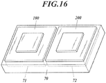
- the biological sensor 100, 200 in the present embodiment includes a first sensor 100 and a second sensor 200 which emit electromagnetic waves of different frequencies toward the human.
- the first sensor 100 and the second sensor 200 basically have a function of detecting minute vibrations of the body surface due to pulsation based on reflection of electromagnetic waves emitted to the human body.
- the first sensor 100 and the second sensor 200 are also called Doppler sensors because they use the frequency shifts of the reflected wave due to the Doppler Effect depending on the speed of an object. Since such a Doppler sensor also detects slight body movements during breathing etc., body movements other than pulse wave may be detected as noise component(s). However, such noise can be removed by using the first sensor 100 and the second sensor 200, and only the pulse wave can be extracted.
- the first sensor 100 is a biological sensor which emits electromagnetic waves of a frequency to reach the blood.
- a biological sensor which emits electromagnetic waves capable of reaching the blood makes use of a change in reflectance of the electromagnetic waves depending on the amount of hemoglobin in the blood.
- Hemoglobin transports oxygen throughout the body. Oxygen deficiency in the tissue (cells) causes symptoms such as rapid blood flow for quick transport of oxygen (palpitations) and rapid breathing for uptake of a large amount of oxygen into the body (shortness of breath).
- the first sensor 100 can detect such body conditions (blood flow condition: pulse wave).
- the first sensor 100 detects minute vibrations of the body surface when the amount of hemoglobin is detected. That is, the waveform of detection data obtained by the first sensor 100 represents both a pulse wave and noise.
- the frequency of the electromagnetic wave reaching the blood is, for example, 270 MHz, but is not particularly limited as long as it can reach the blood to detect the amount of hemoglobin.
- the first sensor 100 is integrated with a receiver that receives reflected waves of the electromagnetic waves emitted by the first sensor 100. That is, the first sensor 100 has both an emission function for emitting electromagnetic waves and a reception function for receiving electromagnetic waves.
- the receiver is connected to a calculation unit (not shown) (included in the driving controller in the present embodiment) so that data communication is possible.
- the data regarding the detected pulse wave and noise is sent to and stored in the calculation unit.
- the second sensor 200 is a biological sensor which emits electromagnetic waves having a frequency for detecting minute vibrations of the body surface.
- the second sensor 200 can detect only minute vibrations of the body surface, that is, noise. That is, the waveform of detection data obtained by the second sensor 200 represents noise only.
- the frequency of the electromagnetic waves for detecting minute vibrations of the body surface is, for example, 10 GHz, but is not particularly limited as long as it can detect the minute vibrations of the body surface.
- the second sensor 200 is integrated with a receiver that receives reflected waves of the electromagnetic waves emitted by the second sensor 200. That is, the second sensor 200 has both an emission function for emitting electromagnetic waves and a reception function for receiving electromagnetic waves.
- the receiver is connected to a calculation unit (not shown, included in the driving controller in the present embodiment) so that data communication is possible.
- the data regarding the detected noise is sent to and stored in the calculation unit.
- the first sensor 100 detects the pulse wave and noise
- the second sensor 200 detects the noise. Therefore, only the pulse wave can be extracted by subtraction of the noise.
- the first sensor 100 and the second sensor 200 are arranged at a large interval, their noise may not correspond to each other (an error occurs). Therefore, the first sensor 100 and the second sensor 200 are arranged adjacent to each other. That is, the first sensor 100 and the second sensor 200 are arranged as close as possible to each other or arranged so as to contact each other.
- the biological sensor 100, 200 in the present embodiment detects human biological information using electromagnetic waves as described above.
- Such electromagnetic waves have a feature that they do not easily pass through various metals such as iron, copper, and aluminum. Therefore, in the present embodiment shown in FIG. 7 , the biological sensors 100, 200 are arranged at positions avoiding the members A1 to A3 (possibly) interfering with the passage of electromagnetic waves with respect to the seat 10.
- the first sensor 100 and the second sensor 200 provided in the seat cushion 11 are arranged at respective positions in the seat 10 such that the member A1 does not overlap the electromagnetic wave emission range R from the first sensor 100 or the second sensor 200.
- the interfering member A1 does not overlap the electromagnetic wave emission ranges R from the first sensor 100 and the second sensor 200, which is also the condition for accurately detecting biological information.
- the first sensor 100 and the second sensor 200 provided in the seat back 14 are arranged in the seat 10 at respective positions such that the emission center C of the electromagnetic waves emitted from the first sensor 100 or the second sensor 200 does not pass through the member A2.
- the interfering member A2 may overlap the emission ranges R as long as the emission centers C of the first sensor 100 and the second sensor 200 do not pass through the interfering member A2. This is also a condition for easily detecting biological information.
- the first sensor 100 and the second sensor 200 are arranged at respective positions closer to the human than the member A3 interfering with the passage of electromagnetic waves is. That is, in the seat 10, the first sensor 100 and the second sensor 200 are preferably arranged at positions closer to the human than the member (for example, the member A3) interfering with the passage of electromagnetic waves is.
- Biological information can be detected even when the interfering members A1 and A2 are arranged closer to the human than the first sensors 100 and the second sensors 200 are, as described above.
- the first sensors 100 and the second sensors 200 are desirably arranged closer to the human than the interfering members A1 and A2 are, because the interfering members A1 and A2 are naturally less likely to interfere with the electromagnetic waves. This is also the condition for accurately detecting biological information.
- the members A1, A2, and A3 interfering with the passage of electromagnetic waves have different relative positions with respect to the first sensors 100 and the second sensors 200, but the members A1, A2, and A3 may be at any of the relative positions because none of them completely interfere with the passage of electromagnetic waves.
- the relative position of the member A3 is the most preferable, and the relative position of the member A1 is also preferable.
- the relative position of the member A2 is not unacceptable.
- FIG. 7 is an example of the seat 10 viewed from the lateral side.
- the members A1, A2, and A3 are each in a relative position near the biological sensor 100, 200 when viewed from the lateral side, they do not interfere with the passage of electromagnetic waves when arranged at different positions in the horizontal direction (left-right direction). Such a relative position is also preferred.
- first sensor 100 and the second sensor 200 are arranged adjacent to each other as described above, which is also the condition for accurately detecting biological information.
- the first sensor 100 and the second sensor 200 are arranged adjacent to each other in the surface direction on the surface to be seated of the seat 10.
- the first sensor 100 and the second sensor 200 have an electromagnetic waves emission surface arranged in parallel or substantially parallel to the surface to be seated of the seat 10.
- the surface to be seated of the seat 10 refers to a surface in contact with human buttocks and thighs.
- the surface to be seated of the seat 10 refers to a surface in contact with the human back (chest side, lumbar side).
- the first sensor 100 and the second sensor 200 are arranged adjacent to each other in the front-rear direction, the left-right direction, or the oblique direction.
- the first sensor 100 and the second sensor 200 are arranged adjacent to each other in the up-down direction, the left-right direction, or the oblique direction.
- the first sensor 100 and the second sensor 200 may be arranged adjacent to each other in the thickness direction of at least one of the seat cushion 11 and the seat back 14. In this case, the first sensor 100 and the second sensor 200 may be arranged so as to partially overlap each other.
- the first sensor 100 and the second sensor 200 are arranged adjacent to each other in the thickness direction of at least one of the seat cushion 11 and the seat back 14, the first sensor 100 which emits electromagnetic waves of a frequency to reach the blood is preferably arranged on the side of the surface to be seated (front side), and the second sensor 200 which emits electromagnetic waves having a frequency for detecting minute vibrations of the body surface is preferably arranged on the side away from the surface to be seated (rear side), so that the emission distances of electromagnetic waves are equivalent.
- the members A1, A2, and A3 interfering with the passage of electromagnetic waves in the present embodiment are metal heater wires 22 and 32 of the seat heaters 20 and 30 respectively shown in FIGs. 5 and 6 .
- the first sensor 100 and the second sensor 2 are arranged in the seat 10 at positions avoiding the heater wires 22 and 32.
- the first sensor 100 and the second sensor 200 are arranged at each of at least two portions of the seat 10 which are separate from each other. More specifically, the first sensor 100 and second sensor 200 are provided in each of the seat cushion 11 and the seat back 14.
- the distances from the position of the heart of the human seated on the seat 10 (the position where the heart is estimated to be present) to each of the at least two portions provided with the biological sensor 100, 200 can be calculated.
- pulse waves can be preferably detected.
- the at least two portions provided with the biological sensor 100, 200 may be limited to be in the seat cushion 11 only or in the seat back 14 only.
- the biological sensor 100, 200 is arranged at at least two portions of the seat cushion 11, it is preferably arranged along either the left or right thigh.
- the biological sensor 100, 200 is arranged at at least two respective portions of the seat back 14, it may be arranged in either the left side or right side of the spine or arranged along the spine, with the position (center) of the spine avoided.
- the first sensor 100 and the second sensor 200 in the seat cushion 11 are provided along the center of the surface to be seated of the seat cushion 11 so that sitting comfort can be improved. That is, they are arranged at portions corresponding to the middle portion (gluteal cleft) of the left and right sciatic bones of human buttocks. In other words, the first sensor 100 and the second sensor 200 are arranged at the middle of the respective positions where the buttocks are mounted in the seat cushion 11 in the seat 10.
- the first sensor 100 and the second sensor 200 are arranged corresponding to the middle portion of the left and right sciatic bones, but is not limited thereto.
- the first sensor 100 and the second sensor 200 provided in the seat cushion 11 may be arranged corresponding to the positions of human femurs.
- reference numerals P1 and P2 in FIG. 5 are candidate portions for arranging the first sensor 100 and the second sensor 200.
- the candidate portion P1 corresponds to the position of the femur of the human seated on the seat 10
- the candidate portion P2 corresponds to the position of the left sciatic bone of the human buttocks.
- the femur in which popliteal arteries pass is suitable for measurement of blood flow conditions with the biological sensor 100, 200.
- the first sensor 100 and the second sensor 200 provided in the seat back 14 are arranged along the center of the surface to be seated of the seat 10, corresponding to the human heart position .
- the chest where the heart is present and through which thoracic aorta passes is suitable for measurement of blood flow conditions with the first sensor 100 and the second sensor 200.
- the heater wires 32 of the seat heater 30 provided in the seat back 14 are arranged avoiding the position of the human heart so that the measurement accuracy is improved with the first sensor 100 and the second sensor 200 each arranged at the human heart position. That is, the heater wires 32 (22) interfering with the passage of electromagnetic waves are arranged so as not to be uniform in density inside the seat 10, and the first sensor 100 and the second sensor 200 are arranged at portions where the density of the heater wires 32 (22) are low (sparse). The higher the density of the heater wires 32 (22) is, the higher temperature it becomes. However, if the first sensor 100 and the second sensor 200 are arranged closer to the surface to be seated than the heater wire 32 (22) is, a problem is unlikely to occur in the detection of biological information.
- the first sensor 100 and the second sensor 200 are arranged at portions each corresponding to the position of the heart, but are not limited thereto.
- the first sensor 100 and the second sensor 200 may be at any position suitable for measurement of the blood flow condition.
- the first sensor 100 and the second sensor 200 may be arranged at portions each corresponding to the center position of the human lumbar region or at portions corresponding to either left or right of the human lumbar region.
- reference numerals P3 and P4 in FIG. 6 are candidate portions for arranging the first sensor 100 and the second sensor 200.
- the candidate portion P3 corresponds to the center position of a lumbar region of the human seated on the seat 10, and the candidate portion P4 corresponds to the left position of the lumbar region of the human.
- Doppler sensors such as the first sensor 100 and the second sensor 200 also detect slight body movements. Therefore, the first sensor 100 and the second sensor 200 are each arranged at a portion corresponding to the body portion with little movement in the human seated on the seat 10, such as buttocks, thighs, or lumbar region. If it is determined that the position of the heart is preferable even if there are many body movements, the first sensor 100 and the second sensor 200 are arranged corresponding to the position of the heart. In addition, although the thigh is a region with little body movement, the thigh in the leg that operates the accelerator or the brake may move a lot. Therefore, the first sensor 100 and the second sensor 200 are preferably arranged corresponding to the thigh in the leg which does not operate the accelerator or the brake.
- the first sensor 100 and the second sensor 200 are arranged avoiding positions of the grooves 12a and 15a (that is, the suspending portions).
- the pulse wave velocity and the degree of arteriosclerosis can be determined using data relating to the blood flow condition(s) in the popliteal artery and the thoracic aorta obtained by measurement with the first sensor 100 and the second sensor 200.
- a calculation program incorporated in advance in the above driving controller or another external device such as a computer
- the driving controller can calculate the blood pressure (arterial pressure) of the human who is the measurement target human. That is, the driving controller functions as the calculation unit described above.
- the seat 10 in the present embodiment is provided in a vehicle capable of travelling through either one of autonomous driving and manual driving which can be switched to each other. Therefore, in order to improve safety, the first sensor 100 and the second sensor 200 may be used in combination with a camera (not shown) that captures the human sitting on the seat 10.
- a camera not shown
- the first sensor 100 and the second sensor 200 may be used in combination with a microphone which collects the voice of the human seated on the seat 10 to confirm whether or not the human is conscious. That is, if the human seated on the seat 10 is urged to speak but does not make a response, it is determined that the driver is unconscious.
- one of the first sensor 100 and the second sensor 200 may be used for detection of biological information including noise, and the other is used for detection of noise. Therefore, only the biological information can be extracted by subtraction of the noise. Furthermore, because the first sensor 100 and the second sensor 200 are arranged adjacent to each other, there is little detection error between the first sensor 100 and the second sensor 200. Accordingly, it is easy to accurately detect biological information.
- human health condition can be calculated from the detected biological information with higher accuracy.
- the seat cushion 11 and the seat back 14 includes the biological sensor, biological information can be detected from at least one of the upper side and the lower side of the human body.
- the first sensor 100 and the second sensor 200 are arranged adjacent to each other in the surface direction on the surface to be seated of the seat 10, the first sensor 100 and the second sensor 200 can be arranged adjacent to each other in the front-rear direction, up-down direction, left-right direction, or oblique direction, in consideration of, for example, the internal structure of the seat cushion 11 or the seat back 14, the sitting comfort of the seat 10, and the like.
- the first sensor 100 and the second sensor 200 are arranged adjacent to each other in the thickness direction of at least one of the seat cushion 11 and the seat back 14, the first sensor 100 and the second sensor 200 can be arranged adjacent to each other even when it is difficult to arrange them adjacent to each other in the surface direction.
- first sensor 100 and the second sensor 200 are arranged so as to partially overlap each other, the first sensor 100 and the second sensor 200 can be arranged adjacent to each other so as not to interfere with each other in detection of biological information.
- the biological sensor 100, 200 is provided along the center of the surface to be seated of the seat 10, the biological sensor 100, 200 is arranged along the gluteal cleft or spine. Therefore, the sitting comfort of the seat 10 would not be impaired.
- the biological sensor 100, 200 is provided on one side of the surface to be seated of the seat 10, the biological sensor 100, 200 is arranged avoiding the positions of the gluteal cleft and the spine. As a result, the distance between the human body and the biological sensor 100, 200 becomes short, so that biological information can be easily detected.
- the seat 40 in this modification includes a built-in seat frame 41 as shown in FIG. 8 .
- the seat frame 41 includes a cushion frame 42 constituting a seat cushion and a seat back frame 43 constituting a seat back.
- the cushion frame 42 and the seat back frame 43 are each provided with a cushion pad 42a and further covered with a covering 42b to constitute the seat 40.
- the cushion frame 42 has a frame shape in a plan view and includes a pair of side frames 44, a pan frame 45, and a connecting pipe 46.
- the paired side frames 44 each extend long in the front-rear direction and are spaced separately in the left-right direction.
- the pan frame 45 is composed of a metal plate connecting the front edges of the paired side frames 44.
- the connection pipe 46 is formed of a metal pipe which connects the rear edges of the paired side frames 44.
- a seat spring 47 is installed between the pan frame 45 and the connecting pipe 46.
- the seat spring 47 includes four spring members 47A to 47D which extend long in the front-rear direction and are arranged in the left-right direction, and resin connection members 48A to 48D which connect the spring members 47A to 47D.
- Each of the spring members 47A to 47D is a bending metal wire.
- the rear ends of the spring members 47A to 47D are respectively formed into hooks 47Aa to 47Da to be hooked to the connecting pipe 46.
- the spring members 47A to 47D respectively extend forward from the hooks 47Aa to 47Da each bending to the left and right directions to form zigzags.
- the spring members 47A to 47D have respective front edges each connected to the pan frame 45 so as not to be displaced.
- the biological sensor 1 is provided in the cushion frame 42.
- the spring members 47A to 47D are the members interfering with the passage of electromagnetic waves, and the biological sensor 1 is arranged at a position avoiding the spring members 47A to 47D.
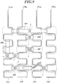
- the connecting members 48A to 48D are provided with biological sensor (s) 1 as shown in FIG. 9 .
- the position(s) of the biological sensor(s) 1 correspond to the middle portion of the left and right sciatic bones of human buttocks or correspond to the position of the thigh.
- the biological sensor(s) are provided at the portion(s) corresponding to the position of the thigh, the portion(s) may correspond to either one thigh or both thighs.
- the connecting members 48A to 48D are arranged at positions closer to the human than the spring members 47A to 47D are. Since the biological sensor(s) 1 are provided on such connecting members 48A to 48D, the measurement results by the biological sensor(s) 1 are less affected by the spring members 47A to 47D.
- the connecting members 48A to 48D are provided so as to connect the spring members 47A to 47D. However, as well as another connecting member 48E in FIG. 9 , the zigzag portions of each of the spring members 47A to 47D each bending to form zigzags may be connected to each other.
- the another connecting member 48E has a portion that connects the adjacent spring members 47A and 47B and a portion that connects the zigzag portions of the spring member 47A, and is formed in a substantially L shape in a plan view.
- the biological sensor (s) 1 can be also arranged on such connecting member 48E.
- the above-described connecting members 48A to 48E are installation plates each having a plate-shaped portion on whose upper surface the biological sensor(s) 1 are installed. That is, the biological sensor(s) 1 are arranged on the connecting members 48A to 48E as described above in the present modification, but are not limited thereto.
- a plate-like member which is located under the cushion pad 42a and on whose upper surface the biological sensor(s) 1 are installed that is, an installation plate placed differently from the connecting members 48A to 48E may be used.
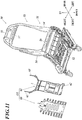
- the cushion pad 42a of the seat 40 has a recess 420 which can accommodate the biological sensor 1 and which is formed at the portion located above the portion where the biological sensor 1 is installed. As shown in FIG. 10 , the recess 420 is formed by recessing the lower surface of the cushion pad 42a.
- the spring members 47A to 47D have respective front edges each connected to the pan frame 45 so as not to be displaced as described above, the biological sensors 1 installed at the respective connecting members 48A to 48D can also be prevented from being displaced.
- the biological sensor 1 may also be arranged on the pan frame 45. Since the pan frame 45 is a member made of metal plate as described above and interferes with the passage of electromagnetic waves, the biological sensor 1 is preferably arranged on the upper side of the pan frame 45. That is, the biological sensor 1 is arranged at a position closer to the human than a member (pan frame 45) interfering with the passage of electromagnetic waves is.
- the biological sensor 1 When arranged on the upper surface of the pan frame 45, the biological sensor 1 may be arranged either at a flat portion near the center or at an inclined portion near the periphery of the pan frame 45.
- the biological sensor 1 may be arranged at a position farther from the human than the pan frame 4 is arranged, if it is arranged at a portion corresponding to an opening 45a formed in the pan frame 45 as shown in FIG. 8 .
- the biological sensor 1 By arranging the biological sensor 1 in this way, electromagnetic waves can be emitted toward the human through the opening 45a.
- the front edges of the paired side frames 44 may be connected to each other using a frame material or a pipe material (not shown) .
- the front edges of the respective spring members 47A to 47D may be connected to the frame material or pipe material.
- the biological sensor 1 may be arranged with a clip or the like (not shown) on the frame material or the pipe material provided instead of the pan frame 45 as described above.
- the biological sensor(s) 1 may be provided so as to be embedded in the cushion pad 42a of the cushion frame 42. If the biological sensor 1 is provided so as to be embedded in the cushion pad 42a, the cushion pad 42a itself may be formed by so-called insert molding while the biological sensor 1 is embedded therein. If the biological sensor 1 is provided so as to be embedded in the cushion pad 42a, a recess (not shown) for accommodating the biological sensor 1 may be formed in the cushion pad 42a so that the biological sensor 1 can be easily installed.
- the method for providing the biological sensor 1 so as to be embedded in the cushion pad 42a is not limited to the insert molding as described above.
- the biological sensor 1 is preferably embedded even after the cushion pad 42a has been molded. That is, a part of the cushion pad 42a (detachable portion 422 in FIG. 10 ) may be detachably formed, such that a recess 421 for accommodating the biological sensor 1 is formed at a position corresponding to the detachable portion 422.
- the biological sensor 1 is provided so as to be embedded in the cushion pad 42a, the detachable portion 422 is detached, the biological sensor 1 is accommodated in the recess 421, and the detachable portion 422 is returned to be fitted again. In this way, the biological sensor 1 can be embedded in the cushion pad 42a.
- the detachable portion 422 can be detached from the lower surface side of the cushion pad 42a, but may be detached from the upper surface side.
- a space in the cushion pad 42a for wiring a harness (not shown) for electrically connecting the biological sensor 1 and an external device (for example, a power generation element, a storage, a control device, and the like), not only for embedding the biological sensor 1.
- a harness for electrically connecting the biological sensor 1 and an external device (for example, a power generation element, a storage, a control device, and the like), not only for embedding the biological sensor 1.
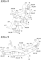
- the seat back frame 43 is provided with a pair of side frames 43a, an upper frame 43b, and a lower member 43c.
- the paired side frames 43a each extend long in the up-down direction and are spaced separately in the left-right direction.
- the upper frame 43b is provided between the upper edges of the paired side frames 43a.
- the lower member 43c is a plate like member provided between the lower edges of the paired side frames 43a.
- a seat spring 43d composed of multiple spring members is provided so as to link the paired side frames 43a between the upper frame 43d and the lower member 43c.
- the multiple spring members of the seat spring 43d extend in the left-right direction and each bend up and down to form zigzags.
- the biological sensor 2 can be also provided on the above-described seat back frame 43, as well as on the above-described cushion frame 42.
- the biological sensor 2 may be provided on either one or both of the paired side frames 43a. In that case, the biological sensor 2 may be attached to either the inner surface or the outer surface of the side frames 43a.
- the biological sensor 2 may be provided on the front surface of the lower member 43c.
- the biological sensor 2 is arranged on the rear surface side of the metal lower member 43c, the biological sensor 2 is arranged so as to correspond to the position of an opening (not shown) formed in the lower member 43c.
- the biological sensor 2 may be provided on the seat spring 43d.
- the biological sensor 2 may be arranged on the connection members (not shown) connecting the respective spring members of the seat spring 43d.
- the biological sensor 2 may be arranged at a portion where the density of the spring members is low.
- the biological sensor 2 may be embedded in a cushion pad (not shown) provided on the front surface side of the seat back frame 43, in the same way as the side of the above-described cushion frame 42.
- the biological sensor 1 is arranged in the seat 40 at a position avoiding the member(s) 47A to 47D interfering with the passage of electromagnetic waves among the members constituting the seat 40. Therefore, the member(s) 47A to 47D interfering with the passage of electromagnetic waves is less likely to interfere with the emission of electromagnetic waves from the biological sensor 1. This makes it easy to accurately detect biological information.
- the biological sensor 1 provided in the cushion frame 42 is arranged at a portion corresponding to the middle portion of the left and right sciatic bones of the human buttocks, the biological sensor 1 can be arranged so as not to knock the sciatic bones, such that the comfort when the human is seated on the seat is not impaired. Furthermore, because the biological sensor 1 provided in the cushion frame 42 is arranged at a portion corresponding to the position of the thighs, the blood flow condition of the popliteal arteries can be grasped. In such a case, biological information can be detected more easily than in the case of thin blood vessels with less blood flow.
- a resin installation plate (connecting member(s) 48A to 48E) attached to the member(s) 47A to 47D and 43d interfering with the passage of electromagnetic waves are arranged at respective positions closer to the human than the member(s) 47A to 47D and 43d is.
- the biological sensor 1 (2) is arranged on the installation plate. Therefore, even if the biological sensor 1 (2) is arranged in the vicinity of the members 47A to 47D and 43d interfering with the passage of the electromagnetic waves, the biological sensor 1 (2) is not easily affected by the member (s) 47A to 47D and 43d interfering with the passage of the electromagnetic waves.
- the biological sensor 1, 2 is arranged at a position corresponding to the position of an opening 45a and farther from the human than the member (pan frame 45, lower member 43c) interfering with the passage of electromagnetic wave.
- the opening 45a is formed in the member 45, 43c interfering with the passage of electromagnetic waves. Therefore, even though the biological sensor 1, 2 is arranged at a position farther from the human than the member 45, 43c interfering with the passage of electromagnetic waves are arranged in the seat 40, the biological sensor 1, 2 is not easily affected by the member 45, 43c interfering with the passage of the electromagnetic waves.
- the member(s) 47A to 47D and 43d interfering with the passage of electromagnetic waves are arranged inside the seat 40 so as not to be uniform in density, and the biological sensor 1, 2 is arranged at a portion where the density of the member(s) 47A to 47B interfering with the passage of electromagnetic waves is low. Therefore, compared with the case where the biological sensor 1, 2 is arranged at a portion where the density of the member(s) 47A to 47B interfering with the passage of electromagnetic waves is high, the biological sensor 1, 2 is not easily affected by the member(s) 47A to 47D and 43d interfering with the passage of the electromagnetic waves.
- the cushion pad 42a in the seat 40 has a part (detachable portion 422) which is configured to be detachable, and includes a recess 421 which accommodates the biological sensor 1 at a position corresponding to the portion 422. Therefore, a space where the biological sensor 1 is arranged can be secured in the seat 40.
- the cushion pad 42a in the seat 40 is formed with the biological sensor 1 embedded therein, installation of the seat 40 can be efficiently performed with the biological sensor 1 embedded in the cushion pad 42a.
- the seat 50 in this modification includes a built-in seat frame 51 as shown in FIG. 11 .
- the seat frame 51 includes a cushion frame 52 constituting a seat cushion and a seat back frame 43 constituting a seat back.
- the cushion frame 52 and the seat back frame 53 are each provided with a cushion pad and further covered with a covering to constitute the seat 50.
- the seat back frame 53 supports a lumbar support device LS which is a pressure receiving member.
- the seat back frame 53 includes a pair of metal plate frames 54 and a pipe frame 55.
- the paired metal plate frames 54 are arranged separately in the left-right direction.
- the pipe frame 55 is connected to the upper edges of the respective paired metal plate frames 54 and formed of a pipe material bending into a U-shape.
- the seat back frame 53 includes a lower frame 56 and a bridging frame 57.
- the lower frame 56 functions as a connecting member which connects the lower portions of the metal plate frames 54 and as a support part.
- the bridging frame 57 functions as a bridging member which connects the left and right of the pipe frame 55.
- the lower frame 56 is a member composed of a metal plate whose upper edge and the lower edge extend slightly forward in a cross-sectional view.
- the left and right edges of the lower frame 56 are welded to be fixed to the portions extending inside in the left-right direction of the metal plate frames 54.
- the lumbar support device LS is attached to the seat back frame 53, receives pressure from the occupant leaning against the seat back and sends it to the seat back frame 53, and changes the shape of portions contacting the lumbar region of the occupant. As a result, supporting condition of the lumbar region can be changed according to the preference of the occupant.
- the lumbar support device LS includes a pressure receiving plate 60, a support member 61, a lower latching portion 62, and a wire(s) 63.
- the pressure receiving plate 60 is made of resin and receives load from the back of the occupant through a cushion member (not shown).
- the support member 61 supports the pressure receiving plate 60 and changes the shape of the pressure receiving plate 60.
- the lower latch 62 fixes the lower portion of the support member 61 (lumbar support device LS) to the lower frame 56.
- the wire(s) 63 fix the upper edge of the support member 61 to the bridging frame 57.
- the biological sensor 2 is provided in the lumbar support device LS.
- metal parts constituting the support member 61 is the member interfering with the passage of electromagnetic waves, and the biological sensor 2 is arranged at a position avoiding the metal parts constituting the support member 61.
- the biological sensor 2 is provided on the surface of the resin pressure receiving plate 60 or at a portion other than the metal parts constituting the support member 61, corresponding to the position of the human heart.
- the biological sensor 2 is arranged in the seat 50 at a position avoiding the member 61 interfering with the passage of electromagnetic waves among the members constituting the seat 50. Therefore, the member 61 interfering with the passage of electromagnetic waves is less likely to interfere with the emission of electromagnetic waves from the biological sensor 2. This makes it easy to accurately detect biological information.
- the biological sensor 2 provided in the lumbar support device LS on the side of the seat back frame 53 is arranged corresponding to the human heart position, blood flow conditions can be grasped from the thoracic aorta. In such a case, biological information can be detected more easily than the case from thin blood vessels with less blood flow.
- the seat 40 in this modification includes a built-in seat frame 41 as shown in FIG. 12 .
- the seat frame 41 includes a cushion frame 42 constituting a seat cushion and a seat back frame 43 constituting a seat back.
- the cushion frame 42 and the seat back frame 43 are each provided with a cushion pad 42a and further covered with a covering 42b to constitute the seat 40.
- the cushion frame 42 has a frame shape in a plan view and includes a pair of side frames 44, a pan frame 45, and a connecting pipe 46.
- the paired side frames 44 each extend long in the front-rear direction and are spaced separately in the left-right direction.
- the pan frame 45 is composed of a metal plate connecting the front edges of the paired side frames 44.
- the connection pipe 46 is formed of a metal pipe which connects the rear edges of the paired side frames 44.
- a seat spring 47 is installed between the pan frame 45 and the connecting pipe 46.
- the seat spring 47 in the cushion frame 42 includes four spring members 47A to 47D which extend long in the front-rear direction and are arranged in the left-right direction.
- Each of the spring members 47A to 47D is a bending metal wire.
- the rear ends of the spring members 47A to 47D are respectively formed into hooks 47Aa to 47Da to be hooked to the connecting pipe 46.
- the spring members 47A to 47D respectively extend forward from the hooks 47Aa to 47Da, each bending to the left and right directions to form zigzags.
- the spring members 47A to 47D have respective front edges each connected to the pan frame 45 so as not to be displaced.
- the cushion frame 42 is provided with the first sensor 100 and the second sensor 200, which are biological sensors.
- the spring members 47A to 47D are the members interfering with the passage of electromagnetic waves, and the first sensor 100 and the second sensor 200 are arranged at positions avoiding the spring members 47A to 47D.
- the first sensor 100 and the second sensor 200 are provided, as shown in FIG. 12 , on the resin connecting members 48A and 48B connecting the spring materials 47C and 47D. That is, the first sensor 100 is provided on the connecting member 48A, and the second sensor 200 is provided on the connecting member 48B.
- the positions of the first sensor 100 and the second sensor 200 correspond to the middle portion of the left and right sciatic bones of human buttocks or correspond to the position of the thigh.
- the portion(s) may correspond to either one thigh or both thighs.
- the first sensor 100 and the second sensor 200 are arranged at positions closer to the human than the connecting members 48A to 48D and the spring members 47A to 47D are. Since the first sensor 100 and the second sensor 200 are provided on such connecting members 48A to 48D, the measurement by the first sensor 100 and the second sensor 200 is less affected by the spring members 47A to 47D.
- the connecting member 48A connects distant portions in the zigzag portions of the adjacent spring members 47C and 47D (47A and 47B).
- the first sensor 100 and the second sensor 200 provided on the connection member 48A can be arranged so as to overlap the spring members 47C or 47D (47A or 47B).
- the connecting member 48B connects nearby portions in the zigzag portions of the adjacent spring members 47C and 47D (47A and 47B).
- the first sensor 100 and the second sensor 200 provided on the connection member 48B may be arranged so as to overlap the spring members 47C or 47D (47A or 47B).
- the above connecting members 48A and 48B are provided so as to connect the adjacent spring members 47C and 47D.
- the connecting members 48A and 48B may be provided so as to appropriately connect the respective spring members 47A to 47D.
- the zigzag portions of each of the spring members 47A to 47D each bending to form zigzags may be connected to each other.
- the first sensor 100 and the second sensor 200 can be also arranged on such connecting member 48C.
- the above-described connecting members 48A to 48C are installation plates each having a plate-shaped portion on whose upper surface the first sensor 100 or the second sensor 200 is installed. That is, the first sensor 100 and the second sensor 200 are arranged on the connecting members 48A to 48C in the present modification as described above, but are not limited thereto.
- the installation plates to be used may be a plate-like member located under the cushion pad 42a and having an upper surface on which the first sensor 100 and the second sensor 200 are installed (that is, installation plates having forms different from those as the connecting members 48A to 48C).
- the cushion pad 42a of the seat 40 has a recess 420 which can accommodate the first sensor 100 and the second sensor 200.
- the recess 420 is formed at a portion located above the portion where the first sensor 100 and the second sensor 200 is installed. As shown in FIG. 14 , the recess 420 is formed by recessing the lower surface of the cushion pad 42a.
- the spring members 47A to 47D have respective front edges each connected to the pan frame 45 so as not to be displaced as described above, the first sensor 100 and the second sensor 200 installed at the respective connecting members 48A to 48D can also be prevented from being displaced.
- first sensor 100 and the second sensor 200 may also be arranged on the pan frame 45. Since the pan frame 45 is a member made of metal plate as described above and interferes with the passage of electromagnetic waves, the first sensor 100 and the second sensor 200 are preferably arranged on the upper side of the pan frame 45. That is, the first sensor 100 and the second sensor 200 are arranged at positions closer to the human than a member (pan frame 45) interfering with the passage of electromagnetic waves is.
- the first sensor 100 and the second sensor 200 may be arranged either at a flat portion near the center or at an inclined portion near the periphery of the pan frame 45.
- first sensor 100 and the second sensor 200 may be arranged at positions farther from the human than the pan frame 4 is arranged, if they are arranged at portions corresponding to an opening 45a formed in the pan frame 45 as shown in FIG. 12 .
- electromagnetic waves can be emitted toward the human through the opening 45a.
- the front edges of the paired side frames 44 may be connected to each other using a frame material or a pipe material (not shown).
- the front edges of the respective spring members 47A to 47D may be connected to the frame material or pipe material.
- the first sensor 100 and the second sensor 200 may be arranged with a clip or the like (not shown) on the frame material or the pipe material provided instead of the pan frame 45 as described above.
- the first sensor 100 and the second sensor 200 may be provided so as to be embedded in the cushion pad 42a of the cushion frame 42. If the first sensor 100 and the second sensor 200 are provided so as to be embedded in the cushion pad 42a, the cushion pad 42a itself may be formed by so-called insert molding where the first sensor 100 and the second sensor 200 are formed in an embedded state. If the first sensor 100 and the second sensor 200 are provided so as to be embedded in the cushion pad 42a, a recess (not shown) for accommodating the first sensor 100 and the second sensor 200 may be formed in the cushion pad 42a so that the first sensor 100 and the second sensor 200 can be easily installed.
- the method for providing the first sensor 100 and the second sensor 200 embedded in the cushion pad 42a is not limited to the insert molding described above.
- the first sensor 100 and the second sensor 200 are preferably embedded even after the cushion pad 42a has been molded. That is, a part of the cushion pad 42a (detachable portion 422 in FIG. 14 ) may be formed to be detachable, and a recess 421 for accommodating the first sensor 100 and the second sensor 200 may be formed at a position corresponding to the detachable portion 422.
- the detachable portion 422 is detached, the first sensor 100 and the second sensor 200 are accommodated in the recess 421, and the detachable portion 422 is returned to be fitted again. In this way, the first sensor 100 and the second sensor 200 can be embedded in the cushion pad 42a.
- the detachable portion 422 can be detached from the lower surface side of the cushion pad 42a, but may be detached from the upper surface side.
- a space in the cushion pad 42a for wiring a harness (not shown) not only for embedding the first sensor 100 and the second sensor 200, but for electrically connecting the first sensor 100 and the second sensor 200 and an external device (for example, a power generation element, a storage, a control device, and the like).
- a harness not shown
- an external device for example, a power generation element, a storage, a control device, and the like.
- a seating sensor 3 may be provided in the cushion pad 42a to detect that the human is seated on the seat 10.
- the biological sensor 100, 200 is linked to the seating sensor 3, and are set to operate when the seating sensor 3 detects that the human is seated on the seat 10.
- the first sensor 100 and the second sensor 200 may be arranged in reverse order. That is, while each of the two connecting members 48A connecting the spring members 47A and 47B is provided with the first sensor 100 and the second sensor 200 as shown in FIG. 13 , the first sensor 100 and the second sensor 200 provided on one connecting member 48A and the first sensor 100 and the second sensor 200 provided on the other connecting member 48A are arranged in reverse order. Even in such a case, biological information can be detected.
- the seat back frame 43 is provided with a pair of side frames 43a, an upper frame 43b, and a lower member 43c.
- the paired side frames 43a each extend long in the up-down direction and are spaced separately in the left-right direction.
- the upper frame 43b is provided between the upper edges of the paired side frames 43a.
- the lower member 43c is a plate like member provided between the lower edges of the paired side frames 43a.
- a seat spring 43d composed of multiple spring members is provided so as to link the paired side frames 43a between the upper frame 43d and the lower member 43c.
- the multiple spring members of the seat spring 43d each extend in the left-right direction and bend up and down to form zigzags.
- the first sensor 100 and the second sensor 200 can be also provided on the above-described seat back frame 43, as well as on the above-described cushion frame 42.
- first sensor 100 and the second sensor 200 may be provided on either one or both of the paired side frames 43a. In that case, the first sensor 100 and the second sensor 200 may be attached to either the inner surface or the outer surface of the side frames 43a.
- the first sensor 100 and the second sensor 200 may be provided on the front surface of the lower member 43c.
- the first sensor 100 and the second sensor 200 are arranged so as to correspond to the position of an opening (not shown) formed in the lower member 43c.
- first sensor 100 and the second sensor 200 may be provided on the seat spring 43d.
- first sensor 100 is provided on the connection member 48D configured similarly to the connection member 48B and connecting the spring members.
- the second sensor 200 is provided on the connection member 48E configured similarly to the connection member 48A and connecting the spring members. If the spring members is not uniform in density, the first sensor 100 and the second sensor 200 may be arranged at portions where the density of the spring members is low.
- the first sensor 100 and the second sensor 200 may be embedded in a cushion pad (not shown) provided on the front surface side of the seat back frame 43, in the same way as the side of the above-described cushion frame 42.
- one of the first sensor 100 and the second sensor 200 may be used for detection of biological information including noise, and the other is used for detection of noise. Therefore, only the biological information can be extracted by subtraction of the noise. Furthermore, because the first sensor 100 and the second sensor 200 are arranged adjacent to each other, there is little detection error between the first sensor 100 and the second sensor 200. Accordingly, it is easy to accurately detect biological information.
- the first sensor 100 and the second sensor 200 are arranged in the seat 40 at positions avoiding the member(s) 47A to 47D interfering with the passage of electromagnetic waves among the members constituting the seat 40. Therefore, the member(s) 47A to 47D interfering with the passage of electromagnetic waves are less likely to interfere with the emission of electromagnetic waves from the first sensor 100 and the second sensor 200. This makes it easy to accurately detect biological information.
- the first sensor 100 and the second sensor 200 provided in the cushion frame 42 are arranged at portions corresponding to the middle portion of the left and right sciatic bones of the human buttocks, the first sensor 100 and the second sensor 200 can be arranged so as not to knock the sciatic bones, such that the comfort when the human is seated on the seat is not impaired. Furthermore, because the first sensor 100 and the second sensor 200 provided in the cushion frame 42 is arranged at a portion corresponding to the position of the thighs, the blood flow condition of the popliteal arteries can be grasped. In such a case, biological information can be detected more easily than in the case of thin blood vessels with less blood flow.
- the resin installation plate (connecting members 48A to 48E) attached to the member(s) 47A to 47D and 43d interfering with the passage of electromagnetic waves are arranged at respective positions closer to the human than the member(s) 47A to 47D and 43d are.
- the first sensor 100 and the second sensor 200 are arranged on the installation plates. Therefore, even if the first sensor 100 and the second sensor 200 are arranged in the vicinity of the member(s) 47A to 47D and 43d interfering with the passage of the electromagnetic waves, the first sensor 100 and the second sensor 200 are not easily affected by the member (s) 47A to 47D and 43d interfering with the passage of the electromagnetic waves.
- the first sensor 100 and the second sensor 200 are arranged at positions corresponding to the position of an opening 45a and being farther from the human than the member (pan frame 45, lower member 43c) interfering with the passage of electromagnetic waves is.
- the opening 45a is formed in the member 45, 43c interfering with the passage of electromagnetic waves. Therefore, even if the first sensor 100 and the second sensor 200 are arranged at positions farther from the human than the member 45, 43c interfering with the passage of electromagnetic waves are arranged in the seat 40, the first sensor 100 and the second sensor 200 are not easily affected by the member 45, 43c interfering with the passage of electromagnetic waves.
- the member(s) 47A to 47D and 43d interfering with the passage of electromagnetic waves are arranged inside the seat 40 so as not to be uniform in density, and the first sensor 100 and the second sensor 200 are arranged at portions where the density of the member(s) 47A to 47B interfering with the passage of electromagnetic waves is low. Therefore, compared with the case where the first sensor 100 and the second sensor 200 are arranged at portions where the density of the member(s) 47A to 47B interfering with the passage of electromagnetic waves is high, the first sensor 100 and the second sensor 200 are not easily affected by the member (s) 47A to 47D and 43d interfering with the passage of electromagnetic waves.
- the cushion pad 42a in the seat 40 has a part (detachable portion 422) which is configured to be detachable, and includes a recess 421 which accommodates the first sensor 100 and the second sensor 200 at positions corresponding to the portion 422. Therefore, a space for arranging the first sensor 100 and the second sensor 200 can be secured in the seat 40.
- the cushion pad 42a in the seat 40 is formed with the first sensor 100 and the second sensor 200 embedded therein, installation of the seat 40 can be efficiently performed with the first sensor 100 and the second sensor 200 embedded in the cushion pad 42a.
- the seat 50 in this modification includes a built-in seat frame 51 as shown in FIG. 15 .
- the seat frame 51 includes a cushion frame 52 constituting a seat cushion and a seat back frame 43 constituting a seat back.
- the cushion frame 52 and the seat back frame 53 are each provided with a cushion pad and further covered with a covering to constitute the seat 50.
- the seat back frame 53 supports a lumbar support device LS which is a pressure receiving member.
- the seat back frame 53 includes a pair of metal plate frames 54 and a pipe frame 55.
- the paired metal plate frames 54 are arranged separately in the left-right direction.
- the pipe frame 55 is connected to the upper edges of the respective paired metal plate frames 54 and formed of a pipe material bending into a U-shape.
- the seat back frame 53 includes a lower frame 56 and a bridging frame 57.
- the lower frame 56 functions as a connecting member which connects the lower portions of the metal plate frames 54 and as a support part.
- the bridging frame 57 functions as a bridging member which connects the left and right of the pipe frame 55.
- the lower frame 56 is a member composed of a metal plate whose upper edge and the lower edge extend slightly forward in a cross-sectional view.
- the left and right edges of the lower frame 56 are welded to be fixed to the portions extending inside in the left-right direction of the metal plate frames 54.
- the lumbar support device LS is attached to the seat back frame 53, receives pressure from the occupant leaning against the seat back and sends it to the seat back frame 53, and changes the shape of portions contacting the lumbar region of the occupant. As a result, supporting condition of the lumbar region can be changed according to the preference of the occupant.
- the lumbar support device LS includes a pressure receiving plate 60, a support member 61, a lower latching portion 62, and a wire(s) 63.
- the pressure receiving plate 60 is made of resin and receives load from the back of the occupant through a cushion member (not shown).
- the support member 61 supports the pressure receiving plate 60 and changes the shape of the pressure receiving plate 60.
- the lower latch 62 fixes the lower portion of the support member 61 (lumbar support device LS) to the lower frame 56.
- the wire(s) 63 fix the upper edge of the support member 61 to the bridging frame 57.
- the first sensor 100 and the second sensor 200 are provided in the lumbar support device LS.
- metal parts constituting the support member 61 is the member interfering with the passage of electromagnetic waves, and the first sensor 100 and the second sensor 200 are arranged at positions avoiding the metal parts constituting the support member 61.
- a mounting portion 64 for mounting the first sensor 100 and the second sensor 200 is integrally formed in the resin pressure receiving plate 60 of the lumbar support device LS.
- the first sensor 100 and the second sensor 200 form a unit including the pressure receiving plate 60 in the lumbar support device LS.
- the mounting portion 64 includes a first recess where the first sensor 100 can be fitted to be mounted, and a second recess where the second sensor 200 can be fitted to be mounted. In use, the first sensor 100 is fitted and mounted to the first recess, and the second sensor 200 is fitted and mounted to the second recess.
- the mounting positions of the first sensor 100 and the second sensor 200 may be reversed if the first sensor 100 and the second sensor 200 have the same shape, and the first recess and the second recess are also formed in the same shape.
- the first sensor 100 and the second sensor 200 in the seat 50 are arranged at positions avoiding the member 61 interfering with the passage of electromagnetic waves among the members constituting the seat 50. Therefore, the member 61 interfering with the passage of electromagnetic waves is less likely to interfere with the emission of electromagnetic waves from the first sensor 100 and the second sensor 200. This makes it easy to accurately detect biological information.
- the biological sensor 100, 200 forms a unit such that the first sensor 100 and the second sensor 200 are arranged adjacent to each other, the first sensor 100 and the second sensor 200 can be easily handled to be attached to the seat 50.
- the biological sensor 100, 200 in this modification forms a unit such that the first sensor 100 and the second sensor 200 are arranged adjacent to each other as shown in FIG. 16 .
- a housing 70 where the first sensor 100 and the second sensor 200 are mounted is used.
- the housing 70 includes a first recess 71 where the first sensor 100 can be fitted to be mounted, and a second recess 72 where the second sensor 200 can be fitted to be mounted.
- the first sensor 100 is fitted and mounted to the first recess 71
- the second sensor 200 is fitted and mounted to the second recess 72.
- the mounting positions of the first sensor 100 and the second sensor 200 may be reversed if the first sensor 100 and the second sensor 200 have the same shape, and the first recess 71 and the second recess 72 are also formed in the same shape.
- the housing 70 itself is attached to an appropriate position of the seat, so that the first sensor 100 and the second sensor 200 can be arranged.
- the biological sensor 100, 200 is a unit with the housing 70 where the first sensor 100 and the second sensor 200 are arranged adjacent to each other, the first sensor 100 and the second sensor 200 can be easily handled to be attached to the seat 50.
- the biological sensor is integrated with a receiver that receives electromagnetic waves emitted from each of the first sensor 100 and the second sensor 200.
- the biological sensor 100, 200 has a receiver 3 as a separate piece.
- the receiver 3 as a separate piece is provided along with the first sensor 100 and the second sensor 200 as shown in FIGs. 17A to 17D . There may be provided one receiver 3 which receives the reflected electromagnetic waves emitted by the first sensor 100 and the second sensor 200, or multiple receivers 3 each corresponding to the first sensor 100 or the second sensor 200.
- the first sensor 100 and the second sensor 200 are arranged so as to be parallel or substantially parallel to the surface to be seated of the seat 10.
- the first sensor 100 and the second sensor 200 may be arranged inclined (at some angle) with respect to the surface to be seated of the seat 80. That is, the first sensor 100 and the second sensor 200 may be arranged in parallel or substantially parallel to the surface to be seated of the seat 80, or non-parallel to the surface to be seated of the seat 80.
- the seat 80 of the present modification includes a seat cushion 81 and a seat back 84.
- the first sensor 100 and the second sensor 200 are arranged adjacent to each other in the left-right direction.
- the receivers 3 are provided below the first sensor 100 and the second sensor 200.
- the arrangement directions of the receivers 3 with respect to the first sensor 100 and the second sensor 200 are not particularly limited.
- the receivers 3 are provided on the lower side of the first sensor 100 and the second sensor 200 in the example shown in FIGS. 17A to 17D , but may be provided on the upper side or may be provided on the lateral side.
- the bidirectional arrow Y represents the spread (surface direction) of the surface to be seated in a lateral view of the seat 80.
- the receiver 3 may be arranged in parallel or substantially parallel to the surface to be seated of the seat 80, or non-parallel to the surface to be seated of the seat 80.
- the first sensor 100 and the second sensor 200 are each arranged so as to be parallel to the surface to be seated of the seat 80, and the receiver 3 is arranged so as to be non-parallel to the surface to be seated of the seat 80.
- the first sensor 100 and the second sensor 200 are each arranged so as to be non-parallel to the surface to be seated of the seat 80, and the receiver 3 is arranged so as to be non-parallel to the surface to be seated of the seat 80, such that the electromagnetic wave emission direction from the first sensor 100 and the second sensor 200 each intersect the electromagnetic wave receiving direction by the receiver 3.
- the first sensor 100 and the second sensor 200 are each arranged so as to be parallel to the surface to be seated of the seat 80, and the receiver 3 is also arranged so as to be parallel to the surface to be seated of the seat 80.
- the first sensor 100 and the second sensor 200 are each arranged so as to be non-parallel to the surface to be seated of the seat 80, and the receiver 3 is arranged so as to be parallel to the surface to be seated of the seat 80.
- FIGs. 17A to 17D can also be applied to the case where the receiver 3 is provided on the lateral side of the first sensor 100 and the second sensor 200.
- the arrangement structures of the first sensor 100, the second sensor 200, and the receiver 3 in the present modification can also be applied to the seat cushion.
- the receivers 3 which receive the electromagnetic waves emitted from the first sensor 100 and the second sensor 200 are provided side by side with respect to the first sensor 100 and the second sensor 200, there is little detection error between the first sensor 100 and the second sensor 200. Therefore, it is easy to accurately detect biological information.
- the receiving accuracy of the electromagnetic waves by the receiver 3 can be adjusted by appropriately changing the angles of the first sensor 100, the second sensor 200, and the receiving unit 3 with respect to the surface to be seated of the seat 80. Therefore, it is easy to more accurately detect biological information.
- the biological sensors 100, 200 are arranged at at least two respective portions of the seat 10 which are separate from each other, that is, at least two portions in the seat cushion 11 and in the seat back 14.
- the seat cushion 11 may be provided with one or more couples of the first sensor 100 and the second sensor 200
- the seat back 14 may be provided with one or more couples of the first sensor 100 and the second sensor 200.
- two or more couples of the first sensor 100 and the second sensor 200 may be provided only in the seat cushion 11.
- two or more couples of the first sensor 100 and the second sensor 200 may be provided only in the seat back 14.
- the seat 90 includes a seat cushion 91, a seat back 94, and movable portions 95 to 99.
- the seat cushion 91 supports human buttocks and thighs.
- the seat back 94 has a lower edge supported by the seat cushion 11.
- the movable portions 95 to 99 are connected to either of the seat cushion 91 or the seat back 94 and move with respect to either the seat cushion 91 or the seat back 94.
- the biological sensor 100, 200 is provided at at least one of the seat cushion 91, the seat back 94, and the movable parts 95 to 99.
- the seat cushion 91 supports the thighs P12 of the human seated on the seat 90, and the seat back 94 supports the trunk P11.
- the trunk P11 includes shoulders, a chest, an abdomen, a lumbar region, and buttocks. The buttocks may be supported by the seat cushion 91.
- the seat cushion 91 and the seat back 94 compose the seat body of the seat 90, and the movable portions 95 to 99 are connected to the seat body.
- the movable portions 95 to 99 include an armrest 95 which supports an arm P13 of the human seated on the seat 90, a headrest 12 which supports the head P14, a neckrest 13 which supports the neck P15 of the occupant P, an ottoman 14 which supports the leg P16, and a footrest 15 which supports the foot P17.
- the biological sensor 100, 200 is provided in each of the seat cushion 91, the seat back 94, and the movable portions 95 to 99.
- the first sensors 100 are arranged next to the respective the second sensors 200 in the left-right direction of the seat 90.
- the biological information can be detected by the biological sensors 100, 200 while the seat 90 is not reclined.
- the biological information is detected by the first sensor 100 and the second sensor 200 provided in each of the seat cushion 91 and the seat back 94.
- the biological information can be detected by the biological sensors 100, 200 while the seat 90 is reclined.
- the biological information is detected by the biological sensors 100, 200 provided in the entire seat 90.
- the biological information may be detected by the biological sensors 100, 200 provided at each of two or more portions selected as appropriate.
- the biological sensor 100, 200 is provided at at least one of the seat cushion 91, the seat back 94, and the movable parts 95 to 99, the biological information can be detected from various parts of the human body. As a result, it is possible to improve accuracy in measurement of the human health condition by detection of biological information.
- the movable portions 95 to 99 are configured to be movable with respect to the seat cushion 91 and the seat back 94, the biological information can be detected when the seat 90 is either reclined or not.
- the seat 90 can be suitably mounted and applied to a vehicle capable of traveling through either one of autonomous driving and manual driving which can be switched to each other, for example.
- the arrangement structure of the biological sensor according to the present invention has high industrial applicability because the member interfering with the passage of electromagnetic waves is less likely to interfere with electromagnetic waves emitted from biological sensor so that biological information can be detected easily and accurately.
Landscapes
- Engineering & Computer Science (AREA)
- Health & Medical Sciences (AREA)
- Life Sciences & Earth Sciences (AREA)
- Transportation (AREA)
- Mechanical Engineering (AREA)
- Aviation & Aerospace Engineering (AREA)
- Physics & Mathematics (AREA)
- Heart & Thoracic Surgery (AREA)
- General Health & Medical Sciences (AREA)
- Public Health (AREA)
- Medical Informatics (AREA)
- Molecular Biology (AREA)
- Surgery (AREA)
- Animal Behavior & Ethology (AREA)
- Pathology (AREA)
- Biophysics (AREA)
- Veterinary Medicine (AREA)
- Biomedical Technology (AREA)
- Cardiology (AREA)
- Physiology (AREA)
- Signal Processing (AREA)
- Hematology (AREA)
- Optics & Photonics (AREA)
- Vascular Medicine (AREA)
- Spectroscopy & Molecular Physics (AREA)
- Artificial Intelligence (AREA)
- Computer Vision & Pattern Recognition (AREA)
- Psychiatry (AREA)
- Seats For Vehicles (AREA)
- Measuring Pulse, Heart Rate, Blood Pressure Or Blood Flow (AREA)
- Measuring And Recording Apparatus For Diagnosis (AREA)
- Chair Legs, Seat Parts, And Backrests (AREA)
Abstract
Description
- The present invention relates to an arrangement structure for a biological sensor.
- When the health condition of the driver who is driving a vehicle deteriorates, it may adversely affect the driving of the vehicle. Therefore, it is desirable to detect the deterioration of the health condition in advance so that some measures can be taken. As for such measures, according to a known technique for grasping the health condition of the driver, biological information such as blood flow and blood pressure is estimated based on the measurement results of pulse waves and the like by a non-contact type blood flow sensor provided to be embedded in the surface to be seated and back of the seat (see Patent Literature 1).
- PTL 1:
JP 2016-168177 A - Biological sensors of a non-contact type are known to emit electromagnetic waves toward a living body and detect biological information based on the waves reflected by the living body. However, the electromagnetic waves emitted toward the living body are unlikely to pass through various metals such as iron, copper, and aluminum. For this reason, metal parts built in the seat may be interfere with electromagnetic waves from the biological sensor provided in the seat, which makes it difficult to accurately detect biological information.
- The present invention has been made in consideration of the above problems, and an object of the present invention is to provide an arrangement structure for a biological sensor that makes it easy to accurately detect biological information.
- In order to solve the above problems, according to the invention of
claim 1, there is provided an arrangement structure for a biological sensor including: - a biological sensor of a non-contact type provided in a seat on which a human is seated, the biological sensor detecting biological information of the human with electromagnetic waves, and
- the biological sensor is arranged at a position in the seat avoiding a member that constitutes the seat and interferes with passage of the electromagnetic waves.
- According to the invention of
claim 2, in the arrangement structure for a biological sensor according toclaim 1,
the seat is provided in a vehicle that travels through autonomous driving or manual driving that are able to be switched to each other. - According to the invention of
claim 3, in the arrangement structure for a biological sensor according toclaim
the biological sensor arranged at the position in the seat emits electromagnetic waves whose emission center does not pass through the member. - According to the invention of claim 4, in the arrangement structure for a biological sensor according to
claim
the biological sensor arranged at the position in the seat emits electromagnetic waves whose emission range does not include the member. - According to the invention of
claim 5, in the arrangement structure for a biological sensor according to any one ofclaims 1 to 4,
the biological sensor is arranged at the position in the seat closer to the human than the member is. - According to the invention of claim 6, the arrangement structure for a biological sensor according to
claim 5 further includes: - a resin installation plate that is attached to the member and that is arranged at a position closer to the human than the member is, and
- the biological sensor is arranged on the installation plate.
- According to the invention of
claim 7, in the arrangement structure for a biological sensor according to any one ofclaims 1 to 4,
the member has an opening, and
the biological sensor is arranged at the position farther from the human than the member is, the position corresponding to a position of the opening. - According to the invention of claim 8, in the arrangement structure for a biological sensor according to any one of
claims 1 to 7,
the member is arranged so as not to be uniform in density inside the seat, and
the biological sensor is arranged at a portion where density of the member is low. - According to the invention of claim 9, in the arrangement structure for a biological sensor according to any one of
claims 1 to 8,
the seat includes a cushion pad that is covered by a covering, and
when a detachable portion of the cushion pad is detached, a recess that accommodates the biological sensor is formed inside the cushion pad. - According to the invention of
claim 10, in the arrangement structure for a biological sensor according to any one ofclaims 1 to 8,
the seat includes a cushion pad that is covered by a covering, and
the cushion pad is formed with the biological sensor embedded in the cushion pad. - According to the invention of
claim 11, in the arrangement structure for a biological sensor according to any one ofclaims 1 to 10,
the biological sensor includes two or more biological sensors that are arranged at at least two respective portions of the seat that are separate from each other. - According to the invention of
claim 12, in the arrangement structure for a biological sensor according toclaim 1,
the biological sensor includes a first sensor and a second sensor that emit electromagnetic waves of different frequencies toward the human, and
the first sensor and the second sensor are arranged adjacent to each other. - According to the invention of
claim 13, in the arrangement structure for a biological sensor according toclaim 12,
the biological sensor includes two or more biological sensors that are arranged at at least two respective portions of the seat that are separate from each other. - According to the invention of
claim 14, in the arrangement structure for a biological sensor according toclaim 12,
the seat includes a seat cushion and a seat back, the seat cushion supporting a human buttock and a human thigh, and the seat back having a lower edge that is supported by the seat cushion,
the biological sensor is provided in at least one of the seat cushion and the seat back, and
the first sensor and the second sensor are arranged adjacent to each other in a surface direction of a surface to be seated of the seat. - According to the invention of
claim 15, in the arrangement structure for a biological sensor according toclaim 12,
the seat includes a seat cushion and a seat back, the seat cushion supporting a human buttock and a human thigh, and the seat back having a lower edge supported by the seat cushion,
the biological sensor is provided in at least one of the seat cushion and the seat back, and
the first sensor and the second sensor are arranged adjacent to each other in a thickness direction of either the seat cushion or the seat back. - According to the invention of
claim 1, the biological sensor is arranged at a position in the seat avoiding a member that constitutes the seat and interferes with passage of the electromagnetic waves. Therefore, the member interfering with the passage of electromagnetic waves are less likely to interfere with the emission of electromagnetic waves from the biological sensor. This makes it easy to accurately detect biological information. - According to the invention of
claim 2, because the seat is provided in a vehicle that travels through autonomous driving or manual driving that are able to be switched to each other, biological information of the driver seated on the seat can be detected. As a result, for example, when the driver's health condition deteriorates, the deterioration can be detected in advance, so that safety can be improved during autonomous driving and during manual driving. - According to the invention of
claim 3, the biological sensor arranged at the position in the seat emits electromagnetic waves whose emission center does not pass through the member interfering with the passage of electromagnetic waves. Therefore, the biological sensor can detect biological information while being affected by the member interfering with the passage of electromagnetic waves. - According to the invention of claim 4, the biological sensor arranged at the position in the seat emits electromagnetic waves whose emission range does not include the member interfering with the passage of electromagnetic waves. Therefore, the biological sensor can detect biological information without being affected by the member interfering with the passage of electromagnetic waves.
- According to the invention of
claim 5, the biological sensor is arranged at the position in the seat closer to the human than the member is. Therefore, the biological sensor is less likely to be affected by the member interfering with the passage of electromagnetic waves. - According to the invention of claim 6, a resin installation plate is attached to the member and is arranged at a position closer to the human than the member is, and the biological sensor is arranged on the installation plate. Therefore, even if the biological sensor is arranged in the vicinity of the member interfering with the passage of the electromagnetic waves, the biological sensor is not easily affected by the member interfering with the passage of the electromagnetic waves.
- According to the invention of
claim 7, the biological sensor is arranged at the position farther from the human than the member interfering with the passage of the electromagnetic waves is, and the position corresponds to a position of the opening formed in the member interfering with the passage of the electromagnetic waves. Therefore, even though the biological sensor is arranged at a position farther from the human than the member interfering with the passage of electromagnetic waves is arranged in the seat, the biological sensor is not easily affected by the member interfering with the passage of the electromagnetic waves. - According to the invention of claim 8, the member interfering with the passage of the electromagnetic waves is arranged so as not to be uniform in density inside the seat, and the biological sensor is arranged at a portion where density of the member interfering with the passage of the electromagnetic waves is low. Therefore, compared with the case where the biological sensor is arranged at a portion where the density of the member interfering with the passage of electromagnetic waves is high, the biological sensor is not easily affected by the member interfering with the passage of the electromagnetic waves.
- According to the invention of claim 9, the seat includes a cushion pad that is covered by a covering, and a recess that accommodates the biological sensor is formed inside the cushion pad when a detachable portion of the cushion pad is detached. Therefore, a space where the biological sensor is arranged can be secured in the seat.
- According to the invention of
claim 10, a cushion pad is formed in the seat with the biological sensor embedded therein. Therefore, installation of the seat can be efficiently performed with the biological sensor embedded in the cushion pad. - According to the invention of
claim 11, the biological sensor includes two or more biological sensors that are arranged at at least two respective portions of the seat that are separate from each other. Therefore, human health condition can be calculated from the detected biological information with higher accuracy. - According to the invention of
claim 12, among a first sensor and a second sensor included in the biological sensor, one is used to detect biological information including noise, and another is used for to detect noise. Therefore, only the biological information can be extracted by subtraction of the noise. Furthermore, because the first sensor and the second sensor are arranged adjacent to each other, there is little detection error between the first sensor and the second sensor. Therefore, it is easy to accurately detect biological information. - According to the invention of
claim 13, biological information can be detected from at least two portions of the human body. Therefore, the human health condition can be calculated from the detected biological information with higher accuracy. - According to the invention of
claim 14, because the biological sensor is provided at at least one of the seat cushion and the seat back, biological information can be detected from at least one of the upper side and the lower side of the human body. - Furthermore, because the first sensor and the second sensor are arranged adjacent to each other in the surface direction on the surface to be seated of the seat, the first sensor and the second sensor can be arranged adjacent to each other in the front-rear direction, up-down direction, left-right direction, or oblique direction, in consideration of, for example, the internal structure of the seat cushion or the seat back, the sitting comfort of the seat, and the like.
- According to the invention of
claim 15, because the biological sensor is provided at at least one of the seat cushion and the seat back, biological information can be detected from at least one of the upper side and the lower side of the human body. - Furthermore, because the first sensor and the second sensor are arranged adjacent to each other in the thickness direction of at least one of the seat cushion and the seat back, the first sensor and the second sensor can be arranged adjacent to each other even when it is difficult to arrange them adjacent to each other in the surface direction.
-
-
FIG. 1 is a perspective view of a seat with a built-in seat heater. -
FIG. 2 is a plan view showing of a seat cushion according to the first embodiment. -
FIG. 3 is a plan view showing of a seat back according to the first embodiment. -
FIG. 4 is a diagram illustrating a positional relationship between an electromagnetic wave and a member that interferes with the electromagnetic wave in the first embodiment. -
FIG. 5 is a plan view showing of a seat cushion according to the second embodiment. -
FIG. 6 is a plan view showing of a seat back according to the second embodiment. -
FIG. 7 is a diagram illustrating a positional relationship between an electromagnetic wave and a member that interferes with the electromagnetic wave in the second embodiment. -
FIG. 8 is a perspective view showing a seat in which spring members are built in a seat cushion according toModification 1. -
FIG. 9 is a plan view showing spring members according toModification 1. -
FIG. 10 is a cross-sectional view of a seat cushion including spring members built therein according toModification 1. -
FIG. 11 is a perspective view showing a seat provided with a lumbar support device according toModification 2. -
FIG. 12 is a perspective view showing a seat in which spring members are built in a seat cushion according toModification 3. -
FIG. 13 is a plan view showing spring members according toModification 3. -
FIG. 14 is a cross-sectional view of a seat cushion including spring members built therein according toModification 3. -
FIG. 15 is a perspective view showing a seat provided with a lumbar support device according to Modification 4. -
FIG. 16 is a perspective view showing the biological sensors according toModification 5 forming a unit. -
FIG. 17A is a diagram illustrating an arrangement example of a first sensor, a second sensor, and a receiver according to Modification 6. -
FIG. 17B is a diagram illustrating an arrangement example of a first sensor, a second sensor, and a receiver according to Modification 6. -
FIG. 17C is a diagram illustrating an arrangement example of a first sensor, a second sensor, and a receiver according to Modification 6. -
FIG. 17D is a diagram illustrating an arrangement example of a first sensor, a second sensor, and a receiver according to Modification 6. -
FIG. 18 is a diagram illustrating an arrangement example of biological sensors in the seat provided with movable portions according toModification 7. -
FIG. 19 is a diagram illustrating a positional relationship between an occupant and biological sensors when a seat provided with movable portions according to Modified 7 is in a reclined state. - Hereinafter, embodiments of the present invention will be described with reference to the drawings. Although a variety of limitations that are technically favorable for carrying out the present invention are described in the following embodiments, the scope of the present invention is not limited to the following embodiments or illustrated examples.
- In
FIG. 1 , the numeral 10 denotes a seat on which a human is seated. Thisseat 10 is provided in a vehicle such as an automobile. In the present embodiment, theseat 10 is particularly provided in a vehicle capable of traveling through either one of autonomous driving and manual driving. The autonomous driving and manual driving can be switched to each other during the travel. - The
seat 10 includes aseat cushion 11 supporting buttocks and thighs of the human, a seat back 14 having a lower edge supported by theseat cushion 11 and serves as a backrest, and aheadrest 17 supporting the human head and provided on the seat back 14 . - The main components of the
seat cushion 11 include a seat cushion frame serving as a skeleton, acushion pad 12 provided on the seat cushion frame, and a covering 13 covering the seat cushion frame and the cushion pad 12 (seeFIG. 2 ). Theseat cushion 11 of the present embodiment further includes aseat heater 20 provided between thecushion pad 12 and thecovering 13. -
Grooves 12a which are long in the left-right direction of theseat 10 are formed on the upper surface of thecushion pad 12. Twogrooves 12a are formed on the upper surface of thecushion pad 12 and divide the upper surface of thecushion pad 12 into the front-rear direction. That is, the upper surface of thecushion pad 12 is divided into a front part, a center part, and a rear part. - The main components of the seat back 14 include a seat back frame serving as a skeleton, a
cushion pad 15 provided on the seat back frame, and a covering 16 covering the seat back frame and the cushion pad 15 (seeFIG. 3 ). - The seat back 14 of the present embodiment further includes a
seat heater 30 provided between thecushion pad 15 and thecovering 16. -
Grooves 15a which are long in the left-right direction of theseat 10 are formed on the front surface of thecushion pad 15. Twogrooves 15a are formed on the front surface of thecushion pad 15 and divide the front surface of thecushion pad 15 into the up-down direction. That is, the upper surface of thecushion pad 15 is divided into an upper part, a center part, and a lower part. - The
seat heater 20 in theseat cushion 11 is a planar heating element that warms theseat cushion 11. As shown inFIG. 2 , the main components of theseat heater 20 includes aplanar base material 21 made of a polyester cloth material and the like, and a heater wire 22 (also referred to as electrically-heated wire) made of metal bonded and fixed to thebase material 21. - As shown in
FIG. 2 , theheater wire 22 bonded and fixed on thebase member 21 includes twoheater wires 22 each meandering in parallel from the rear to the front of theseat cushion 11. The front portions of therespective heater wires 22 are connected to each other. - Although the
heater wires 22 of the present embodiment meander in parallel in the front-rear direction and are fixed on thebase material 21, the arrangement of theheater wires 22 is not limited thereto and may be changed as appropriate. Although theheater wires 22 are fixed on thebase material 21 with an adhesive, theheater wires 22 may be folded inside thebase material 21 to be fixed. - As shown in
FIG. 2 , each of theheater wires 22 includes afront heater wire 22a in a section of the front part on the upper surface of thecushion pad 12, acentral heater wire 22b in a section of the center part, arear heater wire 22c in a section of the rear part, andgroove heater wires 23 which are inserted into therespective grooves 12a and connect thefront heater wire 22a, thecentral heater wire 22b, and therear heater wire 22c. - The
seat heater 30 in the seat back 14 similarly includes abase material 31 and aheater wire 32 as main components. - As shown in
FIG. 3 , each of theheater wires 32 includes anupper heater wire 32a in a section of the upper part on the front surface of thecushion pad 15, acentral heater wire 32b in a section of the center part, alower heater wire 32c in a section of the lower part, andgroove heater wires 33 which connect theupper heater wire 32a, thecentral heater wire 32b, and thelower heater wire 32c and are inserted into therespective grooves 15a. - As described above, because such a
seat 10 is provided in a vehicle which can travel through either of autonomous driving and manual driving which can be switched to each other, the form inappropriate for manual driving and a form appropriate for manual driving can be changed to each other. - During autonomous driving, since the driver is allowed to be in a relaxed condition, the
seat 10 is also changed to a form inappropriate for manual driving. For example, theseat 10 during autonomous driving can change its position so as to face the rear seat or so as to be in a flat condition. - Furthermore, although not shown in the drawings, such a vehicle includes a driving controller which switches between autonomous driving and manual driving, the above-described
seat 10 which can be changed into a plurality of forms, and a seat controller which controls the operation of theseat 10 when changing the form. - When the vehicle on a highway moves to an ordinary road, or when the vehicle is approaching a road having a complicated shape, the driving controller controls the switch of autonomous driving to manual driving. If there is abnormality in the driver's health condition in such a case, forcible switching of autonomous driving to manual driving is not preferable. On the other hand, if the driver's health condition has become worse during manual driving, manual driving may be switched to autonomous driving. In such a case, the health condition needs to be grasped in advance.
- Therefore, the
seat 10 is provided with abiological sensor FIGs 2 and3 . Thebiological sensor - The
biological sensor - The driving controller switches between autonomous driving and manual driving based on the data related to biological information transmitted from the
biological sensor seat 10 as appropriate. - The
biological sensor - Here, electromagnetic waves mean electromagnetic waves in a broad sense including radiowaves of about 100 MHz, microwaves, infrared light, visible light, ultraviolet light, X-rays, and the like. Any suitable electromagnetic waves may be used as long as it does not adversely affect the human body.
- Such electromagnetic waves have a feature that they do not easily pass through various metals such as iron, copper, and aluminum. Therefore, in the present embodiment shown in
FIG. 4 , thebiological sensor seat 10 avoiding the member A1, A2 (possibly) interfering with the passage of electromagnetic waves. - In the example shown in
FIG. 4 , thebiological sensor 1 provided at theseat cushion 11 is arranged in theseat 10 at a position such that the member A1 does not overlap the emission range R of electromagnetic waves emitted from thebiological sensor 1. - That is, when the
biological sensor 1 is provided in theseat 10, a condition for accurately detecting biological information is that the interfering member A1 does not overlap the electromagnetic wave emission range R from thebiological sensor 1. - In the example shown in
FIG. 4 , thebiological sensor 2 provided at the seat back 14 is arranged in theseat 10 at a position such that an emission center C of the electromagnetic waves emitted from thebiological sensor 2 does not pass through the member A2. - That is, when the
biological sensor 2 is provided in theseat 10, the interfering member A2 may overlap the emission range R, as long as the emission center C of the electromagnetic waves emitted from thebiological sensor 2 does not pass through the interfering member A2. This is also a condition for easily detecting biological information. - In the example shown in
FIG. 4 , thebiological sensor 1 is arranged at a position closer to the human than the member A3 interfering with the passage of electromagnetic waves is. That is, in theseat 10, thebiological sensors - Biological information can be detected even when the interfering members A1 and A2 are arranged closer to the human than the
biological sensor biological sensor - The members A1, A2, and A3 interfering with the passage of electromagnetic waves are arranged at different relative positions with respect to the
biological sensors -
FIG. 4 is an example of theseat 10 viewed from the lateral side. As a supplementary explanation, even if the members A1, A2, and A3 are each in a relative position near thebiological sensors - More specifically, the members A1, A2, and A3 interfering with the passage of electromagnetic waves in the present embodiment are
metal heater wires seat heaters FIGs. 2 and3 . Thebiological sensors seat 10 at positions avoiding theheater wires - The
biological sensors seat 10 which are separate from each other. More specifically, both of theseat cushion 11 and the seat back 14 includes thebiological sensors - As shown in
FIG. 2 , thebiological sensor 1 provided in theseat cushion 11 is arranged at a portion corresponding to the middle portion of the left and right sciatic bones of human buttocks so that sitting comfort is improved. In other words, thebiological sensor 1 is arranged in the middle of the position where the buttocks are mounted in theseat cushion 11. - In the present embodiment, the
biological sensor 1 is arranged so as to correspond to the middle portion of the left and right sciatic bones, but is not limited thereto. For example, thebiological sensor 1 provided in theseat cushion 11 may be arranged corresponding to the positions of femurs. - That is, reference numerals P1 and P2 in
FIG. 2 are candidate portions for arranging thebiological sensor 1, and the candidate portions P1 and P2 correspond to the positions of the femurs of the human seated on theseat 10. - The femurs in which popliteal arteries pass are suitable for measurement of blood flow conditions with the
biological sensor 1. - As shown in
FIG. 3 , thebiological sensor 2 provided in the seat back 14 is arranged at a portion corresponding to the position of the human heart. The chest where the heart is present and through which thoracic aorta passes is suitable for measurement of blood flow conditions with thebiological sensor 2. - In other words, the
heater wires 32 of theseat heater 30 provided in the seat back 14 are arranged avoiding the position of the human heart so that the measurement accuracy is improved with thebiological sensor 2 arranged at the human heart position. That is, the heater wires 32 (22) interfering with the passage of electromagnetic waves are arranged so as not to be uniform in density inside theseat 10, and thebiological sensor 2 is arranged at a portion where the density of the heater wires 32 (22) are low (sparse). The higher the density of the heater wires 32 (22) is, the higher temperature it becomes. - In the present embodiment, the
biological sensor 2 is arranged at a portion corresponding to the heart position, but is not limited thereto. Thebiological sensor 2 may be at any position suitable for measurement of the blood flow condition. - The pulse wave velocity and the degree of arteriosclerosis can be determined using data relating to the blood flow condition(s) in the popliteal artery and the thoracic aorta obtained by measurement with the
biological sensor - As described above, the
seat 10 in the present embodiment is provided in a vehicle capable of travelling through either of autonomous driving and manual driving which can be switched to each other. Therefore, in order to improve safety, thebiological sensor seat 10. When thebiological sensor - Furthermore, the
biological sensor seat 10 to confirm whether or not the human is conscious. That is, if the human seated on theseat 10 is urged to speak but does not make a response, it is determined that the driver is unconscious. - According to the present embodiment as described above, the
biological sensor seat 10 at a position avoiding the member A1, A2, A3 interfering with the passage of electromagnetic waves among the members constituting theseat 10. Therefore, the member A1, A2, A3 interfering with the passage of electromagnetic waves is less likely to interfere with the emission of electromagnetic waves from thebiological sensor - Furthermore, because the
seat 10 is provided in a vehicle capable of travelling through either of autonomous driving and manual driving which can be switched to each other, the biological information of the driver seated on the seat can be detected. As a result, for example, when the driver's health condition deteriorates, the deterioration can be detected in advance, so that safety can be improved during autonomous driving and during manual driving. - Furthermore, because the
biological sensor 2 is arranged in theseat 10 at a position such that emission center C of the electromagnetic waves emitted from thebiological sensor 2 do not pass through the member A2 interfering with the passage of electromagnetic waves, thebiological sensor 2 can detect biological information while being affected by the member A2 interfering with the passage of electromagnetic waves. - Furthermore, because the
biological sensor 1 is arranged in theseat 10 at a position such that the member does not overlap the emission range R of the electromagnetic waves emitted from thebiological sensor 1, thebiological sensor 1 can detect biological information without being affected by the member A1, A3 interfering with the passage of electromagnetic waves. - Furthermore, because the
biological sensor 1 is arranged in theseat 10 at a position closer to the human than the member A3 interfering with the passage of electromagnetic waves is, thebiological sensor 1 is less likely to be affected by the member A3 interfering with the passage of electromagnetic waves. - Furthermore, when the
biological sensors - Furthermore, when the
seat cushion 11 and the seat back 14 respectively include thebiological sensors - Furthermore, because the
biological sensor 2 provided in the seat back 14 is arranged corresponding to the human heart position, blood flow conditions can be grasped from the thoracic aorta. In such a case, biological information can be detected more easily than the case from thin blood vessels with less blood flow. - Furthermore, because the
biological sensor 1 provided in theseat cushion 11 is arranged at a portion corresponding to the middle portion of the left and right sciatic bones of the human buttocks, thebiological sensor 1 can be arranged so as not to knock the sciatic bones, such that the comfort when the human is seated on the seat is not impaired. - Furthermore, because the
biological sensor 1 provided in theseat cushion 11 is arranged at a portion corresponding to the position of the thighs, the blood flow condition of the popliteal arteries can be grasped. In such a case, biological information can be detected more easily than in the case of thin blood vessels with less blood flow. - The seat 10 (see
FIG. 1 ) in the present embodiment is provided in a vehicle such as an automobile. The vehicle may be one capable of traveling only through manual driving, or through either one of autonomous driving and manual driving which can be switched to each other. - The
seat 10 includes aseat cushion 11 which supports the human buttocks and thighs, a seat back 14 which has a lower edge supported by theseat cushion 11 and serves as a backrest, and aheadrest 17 which supports the human head and provided on the seat back 14. - The main components of the
seat cushion 11 include a seat cushion frame serving as a skeleton, acushion pad 12 provided on the seat cushion frame, and a covering 13 covering the seat cushion frame and the cushion pad 12 (seeFIG. 5 ). Theseat cushion 11 of the present embodiment further includes aseat heater 20 provided between thecushion pad 12 and thecovering 13. -
Grooves 12a which are long in the left-right direction of theseat 10 are formed on the upper surface of thecushion pad 12. Twogrooves 12a are formed on the upper surface of thecushion pad 12 and divide the upper surface of thecushion pad 12 into the front-rear direction. That is, the upper surface of thecushion pad 12 is divided into a front part, a center part, and a rear part. - The main components of the seat back 14 include a seat back frame serving as a skeleton, a
cushion pad 15 provided on the seat back frame, and a covering 16 that covers the seat back frame and the cushion pad 15 (seeFIG. 6 ). - The seat back 14 of the present embodiment further includes a
seat heater 30 provided between thecushion pad 15 and thecovering 16. -
Grooves 15a which are long in the left-right direction of theseat 10 are formed on the front surface of thecushion pad 15. Twogrooves 15a are formed on the front surface of thecushion pad 15 and divide the front surface of thecushion pad 15 into the up-down direction. That is, the upper surface of thecushion pad 15 is divided into an upper part, a center part, and a lower part. - The
seat heater 20 in theseat cushion 11 is a planar heating element that warms theseat cushion 11. As shown inFIG. 5 , the main components of theseat heater 20 includes aplanar base material 21 made of a polyester cloth material and the like, and a heater wire 22 (also referred to as electrically-heated wire) made of metal bonded and fixed to thebase material 21. - As shown in
FIG. 5 , theheater wire 22 bonded and fixed on thebase member 21 includes twoheater wires 22 each meandering in parallel from the rear to the front of theseat cushion 11. The front portions of therespective heater wires 22 are connected to each other. - Although the
heater wires 22 of the present embodiment meander in parallel in the front-rear direction and are fixed on thebase material 21, the arrangement of theheater wires 22 is not limited thereto and may be changed as appropriate. Although theheater wires 22 are fixed on thebase material 21 with an adhesive, theheater wires 22 may be folded inside thebase material 21 to be fixed. - As shown in
FIG. 5 , each of theheater wires 22 includes afront heater wire 22a in a section of the front part on the upper surface of thecushion pad 12, acentral heater wire 22b in a section of the center part, arear heater wire 22c in a section of the rear part, andgroove heater wires 23 which are inserted into therespective grooves 12a and connect thefront heater wire 22a, thecentral heater wire 22b, and therear heater wire 22c. - The
seat heater 30 in the seat back 14 similarly includes abase material 31 and aheater wire 32 as main components. - As shown in
FIG. 6 , each of theheater wires 32 includes anupper heater wire 32a in a section of the upper part on the front surface of thecushion pad 15, acentral heater wire 32b in a section of the center part, alower heater wire 32c in a section of the lower part, andgroove heater wires 33 which are inserted into therespective grooves 15a and connect theupper heater wire 32a, thecentral heater wire 32b, and thelower heater wire 32c. - If such a
seat 10 is provided in a vehicle which can travel through either one of autonomous driving and manual driving which can be switched to each other, the driver is allowed to be in a relaxed condition during autonomous driving, and theseat 10 is changed to a form inappropriate for manual driving. For example, theseat 10 during autonomous driving can change its position so as to face the rear seat or so as to be in a flat condition. - Furthermore, if the
seat 10 is provided in a vehicle which can travel only through manual driving, theseat 10 can be reclined when the vehicle stops. - Furthermore, although not shown in the drawings, a driving controller is included in the vehicle capable of traveling through either one of autonomous driving and manual driving which can be switched to each other. The driving controller switches between autonomous driving and manual driving, the above-described
seat 10 can be changed into a plurality of forms, and the seat controller controls the operation of theseat 10 when changing the form. - When the vehicle on a highway moves to an ordinary road, or when the vehicle is approaching a road having a complicated shape, the driving controller controls the switch of autonomous driving to manual driving. If there is abnormality in the driver's health condition in such a case, forcible switching of autonomous driving to manual driving is not preferable. On the other hand, if the driver's health condition has become worse during manual driving, manual driving may be switched to autonomous driving. In such a case, the health condition needs to be grasped in advance.
- When the vehicle is capable of traveling through manual driving only, the seat controller may also control the movement of the
seat 10 automatically when the vehicle stops. The health condition may be grasped when the vehicle stops. - For convenience of explanation, the vehicle in the following is capable of traveling through either one of autonomous driving and manual driving which can be switched to each other, but the present invention is not limited thereto. The vehicle may be capable of traveling only through manual driving.
- The
seat 10 is provided with a biological sensor(s) 100, 200 as a means for grasping the health condition of a driver, as shown inFIGs 5 and6 . Thebiological sensor - The
biological sensor - The driving controller switches between autonomous driving and manual driving based on the data related to biological information transmitted from the
biological sensor seat 10 as appropriate. - The
biological sensor - The driving controller switches between autonomous driving and manual driving based on the data related to biological information transmitted from the
biological sensor seat 10 as appropriate. - The
biological sensor - More specifically, the
biological sensor first sensor 100 and asecond sensor 200 which emit electromagnetic waves of different frequencies toward the human. Thefirst sensor 100 and thesecond sensor 200 basically have a function of detecting minute vibrations of the body surface due to pulsation based on reflection of electromagnetic waves emitted to the human body. Thefirst sensor 100 and thesecond sensor 200 are also called Doppler sensors because they use the frequency shifts of the reflected wave due to the Doppler Effect depending on the speed of an object. Since such a Doppler sensor also detects slight body movements during breathing etc., body movements other than pulse wave may be detected as noise component(s). However, such noise can be removed by using thefirst sensor 100 and thesecond sensor 200, and only the pulse wave can be extracted. - The
first sensor 100 is a biological sensor which emits electromagnetic waves of a frequency to reach the blood. A biological sensor which emits electromagnetic waves capable of reaching the blood makes use of a change in reflectance of the electromagnetic waves depending on the amount of hemoglobin in the blood. Hemoglobin transports oxygen throughout the body. Oxygen deficiency in the tissue (cells) causes symptoms such as rapid blood flow for quick transport of oxygen (palpitations) and rapid breathing for uptake of a large amount of oxygen into the body (shortness of breath). Thefirst sensor 100 can detect such body conditions (blood flow condition: pulse wave). - The
first sensor 100 detects minute vibrations of the body surface when the amount of hemoglobin is detected. That is, the waveform of detection data obtained by thefirst sensor 100 represents both a pulse wave and noise. - The frequency of the electromagnetic wave reaching the blood is, for example, 270 MHz, but is not particularly limited as long as it can reach the blood to detect the amount of hemoglobin.
- Further, the
first sensor 100 is integrated with a receiver that receives reflected waves of the electromagnetic waves emitted by thefirst sensor 100. That is, thefirst sensor 100 has both an emission function for emitting electromagnetic waves and a reception function for receiving electromagnetic waves. - The receiver is connected to a calculation unit (not shown) (included in the driving controller in the present embodiment) so that data communication is possible. The data regarding the detected pulse wave and noise is sent to and stored in the calculation unit.
- The
second sensor 200 is a biological sensor which emits electromagnetic waves having a frequency for detecting minute vibrations of the body surface. Thesecond sensor 200 can detect only minute vibrations of the body surface, that is, noise. That is, the waveform of detection data obtained by thesecond sensor 200 represents noise only. - The frequency of the electromagnetic waves for detecting minute vibrations of the body surface is, for example, 10 GHz, but is not particularly limited as long as it can detect the minute vibrations of the body surface.
- Furthermore, the
second sensor 200 is integrated with a receiver that receives reflected waves of the electromagnetic waves emitted by thesecond sensor 200. That is, thesecond sensor 200 has both an emission function for emitting electromagnetic waves and a reception function for receiving electromagnetic waves. - The receiver is connected to a calculation unit (not shown, included in the driving controller in the present embodiment) so that data communication is possible. The data regarding the detected noise is sent to and stored in the calculation unit.
- The
first sensor 100 detects the pulse wave and noise, and thesecond sensor 200 detects the noise. Therefore, only the pulse wave can be extracted by subtraction of the noise. - If the
first sensor 100 and thesecond sensor 200 are arranged at a large interval, their noise may not correspond to each other (an error occurs). Therefore, thefirst sensor 100 and thesecond sensor 200 are arranged adjacent to each other. That is, thefirst sensor 100 and thesecond sensor 200 are arranged as close as possible to each other or arranged so as to contact each other. - The
biological sensor - Such electromagnetic waves have a feature that they do not easily pass through various metals such as iron, copper, and aluminum. Therefore, in the present embodiment shown in
FIG. 7 , thebiological sensors seat 10. - In the example shown in
FIG. 7 , thefirst sensor 100 and thesecond sensor 200 provided in theseat cushion 11 are arranged at respective positions in theseat 10 such that the member A1 does not overlap the electromagnetic wave emission range R from thefirst sensor 100 or thesecond sensor 200. - That is, when the
first sensor 100 and thesecond sensor 200 are provided in theseat 10, the interfering member A1 does not overlap the electromagnetic wave emission ranges R from thefirst sensor 100 and thesecond sensor 200, which is also the condition for accurately detecting biological information. - In the example shown in
FIG. 7 , thefirst sensor 100 and thesecond sensor 200 provided in the seat back 14 are arranged in theseat 10 at respective positions such that the emission center C of the electromagnetic waves emitted from thefirst sensor 100 or thesecond sensor 200 does not pass through the member A2. - That is, when the
first sensor 100 and thesecond sensor 200 are provided in theseat 10, the interfering member A2 may overlap the emission ranges R as long as the emission centers C of thefirst sensor 100 and thesecond sensor 200 do not pass through the interfering member A2. This is also a condition for easily detecting biological information. - In the example shown in
FIG. 7 , thefirst sensor 100 and thesecond sensor 200 are arranged at respective positions closer to the human than the member A3 interfering with the passage of electromagnetic waves is. That is, in theseat 10, thefirst sensor 100 and thesecond sensor 200 are preferably arranged at positions closer to the human than the member (for example, the member A3) interfering with the passage of electromagnetic waves is. - Biological information can be detected even when the interfering members A1 and A2 are arranged closer to the human than the
first sensors 100 and thesecond sensors 200 are, as described above. However, thefirst sensors 100 and thesecond sensors 200 are desirably arranged closer to the human than the interfering members A1 and A2 are, because the interfering members A1 and A2 are naturally less likely to interfere with the electromagnetic waves. This is also the condition for accurately detecting biological information. - The members A1, A2, and A3 interfering with the passage of electromagnetic waves have different relative positions with respect to the
first sensors 100 and thesecond sensors 200, but the members A1, A2, and A3 may be at any of the relative positions because none of them completely interfere with the passage of electromagnetic waves. However, if more accurate detection of biological information is required, the relative position of the member A3 is the most preferable, and the relative position of the member A1 is also preferable. The relative position of the member A2 is not unacceptable. -
FIG. 7 is an example of theseat 10 viewed from the lateral side. As a supplementary explanation, even if the members A1, A2, and A3 are each in a relative position near thebiological sensor - Furthermore, the
first sensor 100 and thesecond sensor 200 are arranged adjacent to each other as described above, which is also the condition for accurately detecting biological information. - Therefore, the
first sensor 100 and thesecond sensor 200 are arranged adjacent to each other in the surface direction on the surface to be seated of theseat 10. In the present embodiment, thefirst sensor 100 and thesecond sensor 200 have an electromagnetic waves emission surface arranged in parallel or substantially parallel to the surface to be seated of theseat 10. - In the case of the
seat cushion 11 inFIG. 5 , the surface to be seated of theseat 10 refers to a surface in contact with human buttocks and thighs. In the case of the seat back 14 inFIG. 6 , the surface to be seated of theseat 10 refers to a surface in contact with the human back (chest side, lumbar side). In the case of theseat cushion 11, thefirst sensor 100 and thesecond sensor 200 are arranged adjacent to each other in the front-rear direction, the left-right direction, or the oblique direction. In the case of the seat back 14, thefirst sensor 100 and thesecond sensor 200 are arranged adjacent to each other in the up-down direction, the left-right direction, or the oblique direction. - Furthermore, as shown in
FIG. 7 , thefirst sensor 100 and thesecond sensor 200 may be arranged adjacent to each other in the thickness direction of at least one of theseat cushion 11 and the seat back 14. In this case, thefirst sensor 100 and thesecond sensor 200 may be arranged so as to partially overlap each other. - As described above, when the
first sensor 100 and thesecond sensor 200 are arranged adjacent to each other in the thickness direction of at least one of theseat cushion 11 and the seat back 14, thefirst sensor 100 which emits electromagnetic waves of a frequency to reach the blood is preferably arranged on the side of the surface to be seated (front side), and thesecond sensor 200 which emits electromagnetic waves having a frequency for detecting minute vibrations of the body surface is preferably arranged on the side away from the surface to be seated (rear side), so that the emission distances of electromagnetic waves are equivalent. - The arrangement of the
first sensor 100 and thesecond sensor 200 is now described more specifically. the members A1, A2, and A3 interfering with the passage of electromagnetic waves in the present embodiment aremetal heater wires seat heaters FIGs. 5 and6 . Thefirst sensor 100 and thesecond sensor 2 are arranged in theseat 10 at positions avoiding theheater wires - The
first sensor 100 and thesecond sensor 200 are arranged at each of at least two portions of theseat 10 which are separate from each other. More specifically, thefirst sensor 100 andsecond sensor 200 are provided in each of theseat cushion 11 and the seat back 14. - As described above, when the
first sensor 100 and thesecond sensor 200 are arranged at each of at least two portions of theseat 10 which are separate from each other, the distances from the position of the heart of the human seated on the seat 10 (the position where the heart is estimated to be present) to each of the at least two portions provided with thebiological sensor - It is necessary for calculation of the blood pressure of a measurement target human to consider the length of the artery. However, since there are individual differences in the human body, pulse waves are detected with the
seat 10 as a reference as described above. - Furthermore, in order that the length of the artery is easily discriminated and the accuracy of pulse wave detection is improved, the at least two portions provided with the
biological sensor seat cushion 11 only or in the seat back 14 only. When thebiological sensor seat cushion 11, it is preferably arranged along either the left or right thigh. When thebiological sensor - As shown in
FIG. 5 , thefirst sensor 100 and thesecond sensor 200 in theseat cushion 11 are provided along the center of the surface to be seated of theseat cushion 11 so that sitting comfort can be improved. That is, they are arranged at portions corresponding to the middle portion (gluteal cleft) of the left and right sciatic bones of human buttocks. In other words, thefirst sensor 100 and thesecond sensor 200 are arranged at the middle of the respective positions where the buttocks are mounted in theseat cushion 11 in theseat 10. - In the present embodiment, the
first sensor 100 and thesecond sensor 200 are arranged corresponding to the middle portion of the left and right sciatic bones, but is not limited thereto. For example, as indicated by two-dot chain lines inFIG. 5 , thefirst sensor 100 and thesecond sensor 200 provided in theseat cushion 11 may be arranged corresponding to the positions of human femurs. - That is, reference numerals P1 and P2 in
FIG. 5 are candidate portions for arranging thefirst sensor 100 and thesecond sensor 200. The candidate portion P1 corresponds to the position of the femur of the human seated on theseat 10, and the candidate portion P2 corresponds to the position of the left sciatic bone of the human buttocks. - The femur in which popliteal arteries pass is suitable for measurement of blood flow conditions with the
biological sensor - As shown in
FIG. 6 , thefirst sensor 100 and thesecond sensor 200 provided in the seat back 14 are arranged along the center of the surface to be seated of theseat 10, corresponding to the human heart position . The chest where the heart is present and through which thoracic aorta passes is suitable for measurement of blood flow conditions with thefirst sensor 100 and thesecond sensor 200. - In other words, the
heater wires 32 of theseat heater 30 provided in the seat back 14 are arranged avoiding the position of the human heart so that the measurement accuracy is improved with thefirst sensor 100 and thesecond sensor 200 each arranged at the human heart position. That is, the heater wires 32 (22) interfering with the passage of electromagnetic waves are arranged so as not to be uniform in density inside theseat 10, and thefirst sensor 100 and thesecond sensor 200 are arranged at portions where the density of the heater wires 32 (22) are low (sparse). The higher the density of the heater wires 32 (22) is, the higher temperature it becomes. However, if thefirst sensor 100 and thesecond sensor 200 are arranged closer to the surface to be seated than the heater wire 32 (22) is, a problem is unlikely to occur in the detection of biological information. - In the present embodiment, the
first sensor 100 and thesecond sensor 200 are arranged at portions each corresponding to the position of the heart, but are not limited thereto. Thefirst sensor 100 and thesecond sensor 200 may be at any position suitable for measurement of the blood flow condition. For example, as indicated by two-dot chain lines inFIG. 6 , thefirst sensor 100 and thesecond sensor 200 may be arranged at portions each corresponding to the center position of the human lumbar region or at portions corresponding to either left or right of the human lumbar region. - That is, reference numerals P3 and P4 in
FIG. 6 are candidate portions for arranging thefirst sensor 100 and thesecond sensor 200. The candidate portion P3 corresponds to the center position of a lumbar region of the human seated on theseat 10, and the candidate portion P4 corresponds to the left position of the lumbar region of the human. - As described above, Doppler sensors such as the
first sensor 100 and thesecond sensor 200 also detect slight body movements. Therefore, thefirst sensor 100 and thesecond sensor 200 are each arranged at a portion corresponding to the body portion with little movement in the human seated on theseat 10, such as buttocks, thighs, or lumbar region. If it is determined that the position of the heart is preferable even if there are many body movements, thefirst sensor 100 and thesecond sensor 200 are arranged corresponding to the position of the heart. In addition, although the thigh is a region with little body movement, the thigh in the leg that operates the accelerator or the brake may move a lot. Therefore, thefirst sensor 100 and thesecond sensor 200 are preferably arranged corresponding to the thigh in the leg which does not operate the accelerator or the brake. - Furthermore, at the position of the
groove 12a in thecushion pad 12 of theseat cushion 11 and the position of thegroove 15a in thecushion pad 15 of the seat back 14, there is provided a metal wire for forming suspending portions of thecoverings 13 and 16 (see the suspendingportions 49 inFIG. 14 ). Thefirst sensor 100 and thesecond sensor 200 are arranged avoiding positions of thegrooves - The pulse wave velocity and the degree of arteriosclerosis can be determined using data relating to the blood flow condition(s) in the popliteal artery and the thoracic aorta obtained by measurement with the
first sensor 100 and thesecond sensor 200. Here, a calculation program incorporated in advance in the above driving controller (or another external device such as a computer) is used. Furthermore, on the basis of the pulse wave velocity and the degree of arteriosclerosis, the driving controller can calculate the blood pressure (arterial pressure) of the human who is the measurement target human. That is, the driving controller functions as the calculation unit described above. - As described above, the
seat 10 in the present embodiment is provided in a vehicle capable of travelling through either one of autonomous driving and manual driving which can be switched to each other. Therefore, in order to improve safety, thefirst sensor 100 and thesecond sensor 200 may be used in combination with a camera (not shown) that captures the human sitting on theseat 10. When thefirst sensor 100 and thesecond sensor 200 are used in combination with a camera, it can be determined whether or not the human who is seated but does not put his hand(s) on the steering wheel H is deteriorating in his health, as well as whether or not he is just asleep. - Furthermore, the
first sensor 100 and thesecond sensor 200 may be used in combination with a microphone which collects the voice of the human seated on theseat 10 to confirm whether or not the human is conscious. That is, if the human seated on theseat 10 is urged to speak but does not make a response, it is determined that the driver is unconscious. - According to the present embodiment as described above, one of the
first sensor 100 and thesecond sensor 200 may be used for detection of biological information including noise, and the other is used for detection of noise. Therefore, only the biological information can be extracted by subtraction of the noise. Furthermore, because thefirst sensor 100 and thesecond sensor 200 are arranged adjacent to each other, there is little detection error between thefirst sensor 100 and thesecond sensor 200. Accordingly, it is easy to accurately detect biological information. - Furthermore, because biological information can be detected from at least two portions in the human body, human health condition can be calculated from the detected biological information with higher accuracy.
- Furthermore, because at least one of the
seat cushion 11 and the seat back 14 includes the biological sensor, biological information can be detected from at least one of the upper side and the lower side of the human body. - Furthermore, because the
first sensor 100 and thesecond sensor 200 are arranged adjacent to each other in the surface direction on the surface to be seated of theseat 10, thefirst sensor 100 and thesecond sensor 200 can be arranged adjacent to each other in the front-rear direction, up-down direction, left-right direction, or oblique direction, in consideration of, for example, the internal structure of theseat cushion 11 or the seat back 14, the sitting comfort of theseat 10, and the like. - Furthermore, because the
first sensor 100 and thesecond sensor 200 are arranged adjacent to each other in the thickness direction of at least one of theseat cushion 11 and the seat back 14, thefirst sensor 100 and thesecond sensor 200 can be arranged adjacent to each other even when it is difficult to arrange them adjacent to each other in the surface direction. - Furthermore, because the
first sensor 100 and thesecond sensor 200 are arranged so as to partially overlap each other, thefirst sensor 100 and thesecond sensor 200 can be arranged adjacent to each other so as not to interfere with each other in detection of biological information. - Furthermore, if the
biological sensor seat 10, thebiological sensor seat 10 would not be impaired. - If the
biological sensor seat 10, thebiological sensor biological sensor - The embodiments to which the present invention can be applied are not limited to the above-described embodiment, and the scope of the present invention can be suitably changed without leaving the scope of the invention. The modifications are described below. The modifications described below can be combined if possible.
- The
seat 40 in this modification includes a built-inseat frame 41 as shown inFIG. 8 . Theseat frame 41 includes acushion frame 42 constituting a seat cushion and a seat backframe 43 constituting a seat back. - The
cushion frame 42 and the seat backframe 43 are each provided with acushion pad 42a and further covered with a covering 42b to constitute theseat 40. - The
cushion frame 42 has a frame shape in a plan view and includes a pair of side frames 44, apan frame 45, and a connectingpipe 46. The paired side frames 44 each extend long in the front-rear direction and are spaced separately in the left-right direction. Thepan frame 45 is composed of a metal plate connecting the front edges of the paired side frames 44. Theconnection pipe 46 is formed of a metal pipe which connects the rear edges of the paired side frames 44. - A seat spring 47 is installed between the
pan frame 45 and the connectingpipe 46. - The seat spring 47 includes four
spring members 47A to 47D which extend long in the front-rear direction and are arranged in the left-right direction, andresin connection members 48A to 48D which connect thespring members 47A to 47D. - Each of the
spring members 47A to 47D is a bending metal wire. The rear ends of thespring members 47A to 47D are respectively formed into hooks 47Aa to 47Da to be hooked to the connectingpipe 46. Thespring members 47A to 47D respectively extend forward from the hooks 47Aa to 47Da each bending to the left and right directions to form zigzags. As shown inFIG.8 , thespring members 47A to 47D have respective front edges each connected to thepan frame 45 so as not to be displaced. - The
biological sensor 1 is provided in thecushion frame 42. In the present modification, thespring members 47A to 47D are the members interfering with the passage of electromagnetic waves, and thebiological sensor 1 is arranged at a position avoiding thespring members 47A to 47D. - More specifically, the connecting
members 48A to 48D are provided with biological sensor (s) 1 as shown inFIG. 9 . The position(s) of the biological sensor(s) 1 correspond to the middle portion of the left and right sciatic bones of human buttocks or correspond to the position of the thigh. When the biological sensor(s) are provided at the portion(s) corresponding to the position of the thigh, the portion(s) may correspond to either one thigh or both thighs. - The connecting
members 48A to 48D are arranged at positions closer to the human than thespring members 47A to 47D are. Since the biological sensor(s) 1 are provided on such connectingmembers 48A to 48D, the measurement results by the biological sensor(s) 1 are less affected by thespring members 47A to 47D. - The connecting
members 48A to 48D are provided so as to connect thespring members 47A to 47D. However, as well as another connectingmember 48E inFIG. 9 , the zigzag portions of each of thespring members 47A to 47D each bending to form zigzags may be connected to each other. The another connectingmember 48E has a portion that connects theadjacent spring members spring member 47A, and is formed in a substantially L shape in a plan view. The biological sensor (s) 1 can be also arranged on such connectingmember 48E. - In other words, the above-described connecting
members 48A to 48E are installation plates each having a plate-shaped portion on whose upper surface the biological sensor(s) 1 are installed. That is, the biological sensor(s) 1 are arranged on the connectingmembers 48A to 48E as described above in the present modification, but are not limited thereto. A plate-like member which is located under thecushion pad 42a and on whose upper surface the biological sensor(s) 1 are installed (that is, an installation plate placed differently from the connectingmembers 48A to 48E) may be used. - As the
biological sensor 1 may be disposed on each of the connectingmembers 48A to 48E, thecushion pad 42a of theseat 40 has arecess 420 which can accommodate thebiological sensor 1 and which is formed at the portion located above the portion where thebiological sensor 1 is installed. As shown inFIG. 10 , therecess 420 is formed by recessing the lower surface of thecushion pad 42a. - Furthermore, because the
spring members 47A to 47D have respective front edges each connected to thepan frame 45 so as not to be displaced as described above, thebiological sensors 1 installed at the respective connectingmembers 48A to 48D can also be prevented from being displaced. - Furthermore, the
biological sensor 1 may also be arranged on thepan frame 45. Since thepan frame 45 is a member made of metal plate as described above and interferes with the passage of electromagnetic waves, thebiological sensor 1 is preferably arranged on the upper side of thepan frame 45. That is, thebiological sensor 1 is arranged at a position closer to the human than a member (pan frame 45) interfering with the passage of electromagnetic waves is. - When arranged on the upper surface of the
pan frame 45, thebiological sensor 1 may be arranged either at a flat portion near the center or at an inclined portion near the periphery of thepan frame 45. - However, the
biological sensor 1 may be arranged at a position farther from the human than the pan frame 4 is arranged, if it is arranged at a portion corresponding to anopening 45a formed in thepan frame 45 as shown inFIG. 8 . By arranging thebiological sensor 1 in this way, electromagnetic waves can be emitted toward the human through theopening 45a. - Furthermore, instead of the
pan frame 45, the front edges of the paired side frames 44 may be connected to each other using a frame material or a pipe material (not shown) . In this case, the front edges of therespective spring members 47A to 47D may be connected to the frame material or pipe material. Thebiological sensor 1 may be arranged with a clip or the like (not shown) on the frame material or the pipe material provided instead of thepan frame 45 as described above. - Furthermore, as shown in
FIG. 10 , the biological sensor(s) 1 may be provided so as to be embedded in thecushion pad 42a of thecushion frame 42. If thebiological sensor 1 is provided so as to be embedded in thecushion pad 42a, thecushion pad 42a itself may be formed by so-called insert molding while thebiological sensor 1 is embedded therein. If thebiological sensor 1 is provided so as to be embedded in thecushion pad 42a, a recess (not shown) for accommodating thebiological sensor 1 may be formed in thecushion pad 42a so that thebiological sensor 1 can be easily installed. - The method for providing the
biological sensor 1 so as to be embedded in thecushion pad 42a is not limited to the insert molding as described above. Thebiological sensor 1 is preferably embedded even after thecushion pad 42a has been molded. That is, a part of thecushion pad 42a (detachable portion 422 inFIG. 10 ) may be detachably formed, such that arecess 421 for accommodating thebiological sensor 1 is formed at a position corresponding to thedetachable portion 422. - If the
biological sensor 1 is provided so as to be embedded in thecushion pad 42a, thedetachable portion 422 is detached, thebiological sensor 1 is accommodated in therecess 421, and thedetachable portion 422 is returned to be fitted again. In this way, thebiological sensor 1 can be embedded in thecushion pad 42a. - In the present modification, the
detachable portion 422 can be detached from the lower surface side of thecushion pad 42a, but may be detached from the upper surface side. - There may be formed a space in the
cushion pad 42a for wiring a harness (not shown) for electrically connecting thebiological sensor 1 and an external device (for example, a power generation element, a storage, a control device, and the like), not only for embedding thebiological sensor 1. - As shown in
FIG. 8 , the seat backframe 43 is provided with a pair ofside frames 43a, anupper frame 43b, and alower member 43c. The pairedside frames 43a each extend long in the up-down direction and are spaced separately in the left-right direction. Theupper frame 43b is provided between the upper edges of the pairedside frames 43a. Thelower member 43c is a plate like member provided between the lower edges of the pairedside frames 43a. Aseat spring 43d composed of multiple spring members is provided so as to link the pairedside frames 43a between theupper frame 43d and thelower member 43c. - The multiple spring members of the
seat spring 43d extend in the left-right direction and each bend up and down to form zigzags. Thebiological sensor 2 can be also provided on the above-described seat backframe 43, as well as on the above-describedcushion frame 42. - That is, the
biological sensor 2 may be provided on either one or both of the pairedside frames 43a. In that case, thebiological sensor 2 may be attached to either the inner surface or the outer surface of the side frames 43a. - The
biological sensor 2 may be provided on the front surface of thelower member 43c. When thebiological sensor 2 is arranged on the rear surface side of the metallower member 43c, thebiological sensor 2 is arranged so as to correspond to the position of an opening (not shown) formed in thelower member 43c. - Furthermore, the
biological sensor 2 may be provided on theseat spring 43d. In that case, as well as in the case on the above-describedcushion frame 42, thebiological sensor 2 may be arranged on the connection members (not shown) connecting the respective spring members of theseat spring 43d. Alternatively, if the spring members are not uniform in density, thebiological sensor 2 may be arranged at a portion where the density of the spring members is low. - The
biological sensor 2 may be embedded in a cushion pad (not shown) provided on the front surface side of the seat backframe 43, in the same way as the side of the above-describedcushion frame 42. - According to the present modification, the
biological sensor 1 is arranged in theseat 40 at a position avoiding the member(s) 47A to 47D interfering with the passage of electromagnetic waves among the members constituting theseat 40. Therefore, the member(s) 47A to 47D interfering with the passage of electromagnetic waves is less likely to interfere with the emission of electromagnetic waves from thebiological sensor 1. This makes it easy to accurately detect biological information. - Furthermore, because the
biological sensor 1 provided in thecushion frame 42 is arranged at a portion corresponding to the middle portion of the left and right sciatic bones of the human buttocks, thebiological sensor 1 can be arranged so as not to knock the sciatic bones, such that the comfort when the human is seated on the seat is not impaired. Furthermore, because thebiological sensor 1 provided in thecushion frame 42 is arranged at a portion corresponding to the position of the thighs, the blood flow condition of the popliteal arteries can be grasped. In such a case, biological information can be detected more easily than in the case of thin blood vessels with less blood flow. - Furthermore, a resin installation plate (connecting member(s) 48A to 48E) attached to the member(s) 47A to 47D and 43d interfering with the passage of electromagnetic waves are arranged at respective positions closer to the human than the member(s) 47A to 47D and 43d is. The biological sensor 1 (2) is arranged on the installation plate. Therefore, even if the biological sensor 1 (2) is arranged in the vicinity of the
members 47A to 47D and 43d interfering with the passage of the electromagnetic waves, the biological sensor 1 (2) is not easily affected by the member (s) 47A to 47D and 43d interfering with the passage of the electromagnetic waves. - Furthermore, in the
seat 40, thebiological sensor opening 45a and farther from the human than the member (pan frame 45,lower member 43c) interfering with the passage of electromagnetic wave. Theopening 45a is formed in themember biological sensor member seat 40, thebiological sensor member - In addition, the member(s) 47A to 47D and 43d interfering with the passage of electromagnetic waves are arranged inside the
seat 40 so as not to be uniform in density, and thebiological sensor biological sensor biological sensor - Furthermore, the
cushion pad 42a in theseat 40 has a part (detachable portion 422) which is configured to be detachable, and includes arecess 421 which accommodates thebiological sensor 1 at a position corresponding to theportion 422. Therefore, a space where thebiological sensor 1 is arranged can be secured in theseat 40. - Furthermore, because the
cushion pad 42a in theseat 40 is formed with thebiological sensor 1 embedded therein, installation of theseat 40 can be efficiently performed with thebiological sensor 1 embedded in thecushion pad 42a. - The
seat 50 in this modification includes a built-inseat frame 51 as shown inFIG. 11 . Theseat frame 51 includes acushion frame 52 constituting a seat cushion and a seat backframe 43 constituting a seat back. - The
cushion frame 52 and the seat backframe 53 are each provided with a cushion pad and further covered with a covering to constitute theseat 50. - The seat back
frame 53 supports a lumbar support device LS which is a pressure receiving member. The seat backframe 53 includes a pair of metal plate frames 54 and apipe frame 55. The paired metal plate frames 54 are arranged separately in the left-right direction. Thepipe frame 55 is connected to the upper edges of the respective paired metal plate frames 54 and formed of a pipe material bending into a U-shape. - The seat back
frame 53 includes alower frame 56 and abridging frame 57. Thelower frame 56 functions as a connecting member which connects the lower portions of the metal plate frames 54 and as a support part. The bridgingframe 57 functions as a bridging member which connects the left and right of thepipe frame 55. - The
lower frame 56 is a member composed of a metal plate whose upper edge and the lower edge extend slightly forward in a cross-sectional view. The left and right edges of thelower frame 56 are welded to be fixed to the portions extending inside in the left-right direction of the metal plate frames 54. - The lumbar support device LS is attached to the seat back
frame 53, receives pressure from the occupant leaning against the seat back and sends it to the seat backframe 53, and changes the shape of portions contacting the lumbar region of the occupant. As a result, supporting condition of the lumbar region can be changed according to the preference of the occupant. - The lumbar support device LS includes a
pressure receiving plate 60, asupport member 61, alower latching portion 62, and a wire(s) 63. Thepressure receiving plate 60 is made of resin and receives load from the back of the occupant through a cushion member (not shown). Thesupport member 61 supports thepressure receiving plate 60 and changes the shape of thepressure receiving plate 60. Thelower latch 62 fixes the lower portion of the support member 61 (lumbar support device LS) to thelower frame 56. The wire(s) 63 fix the upper edge of thesupport member 61 to thebridging frame 57. - The
biological sensor 2 is provided in the lumbar support device LS. In the present modification, metal parts constituting thesupport member 61 is the member interfering with the passage of electromagnetic waves, and thebiological sensor 2 is arranged at a position avoiding the metal parts constituting thesupport member 61. - More specifically, the
biological sensor 2 is provided on the surface of the resinpressure receiving plate 60 or at a portion other than the metal parts constituting thesupport member 61, corresponding to the position of the human heart. - According to the present embodiment as described above, the biological sensor 2is arranged in the
seat 50 at a position avoiding themember 61 interfering with the passage of electromagnetic waves among the members constituting theseat 50. Therefore, themember 61 interfering with the passage of electromagnetic waves is less likely to interfere with the emission of electromagnetic waves from thebiological sensor 2. This makes it easy to accurately detect biological information. - Furthermore, because the
biological sensor 2 provided in the lumbar support device LS on the side of the seat backframe 53 is arranged corresponding to the human heart position, blood flow conditions can be grasped from the thoracic aorta. In such a case, biological information can be detected more easily than the case from thin blood vessels with less blood flow. - The
seat 40 in this modification includes a built-inseat frame 41 as shown inFIG. 12 . Theseat frame 41 includes acushion frame 42 constituting a seat cushion and a seat backframe 43 constituting a seat back. - The
cushion frame 42 and the seat backframe 43 are each provided with acushion pad 42a and further covered with a covering 42b to constitute theseat 40. - The
cushion frame 42 has a frame shape in a plan view and includes a pair of side frames 44, apan frame 45, and a connectingpipe 46. The paired side frames 44 each extend long in the front-rear direction and are spaced separately in the left-right direction. Thepan frame 45 is composed of a metal plate connecting the front edges of the paired side frames 44. Theconnection pipe 46 is formed of a metal pipe which connects the rear edges of the paired side frames 44. - A seat spring 47 is installed between the
pan frame 45 and the connectingpipe 46. - First, the
cushion frame 42 will be explained. - The seat spring 47 in the
cushion frame 42 includes fourspring members 47A to 47D which extend long in the front-rear direction and are arranged in the left-right direction. - Each of the
spring members 47A to 47D is a bending metal wire. The rear ends of thespring members 47A to 47D are respectively formed into hooks 47Aa to 47Da to be hooked to the connectingpipe 46. Thespring members 47A to 47D respectively extend forward from the hooks 47Aa to 47Da, each bending to the left and right directions to form zigzags. As shown inFIG.12 , thespring members 47A to 47D have respective front edges each connected to thepan frame 45 so as not to be displaced. - The
cushion frame 42 is provided with thefirst sensor 100 and thesecond sensor 200, which are biological sensors. In the present modification, thespring members 47A to 47D are the members interfering with the passage of electromagnetic waves, and thefirst sensor 100 and thesecond sensor 200 are arranged at positions avoiding thespring members 47A to 47D. - More specifically, the
first sensor 100 and thesecond sensor 200 are provided, as shown inFIG. 12 , on theresin connecting members spring materials first sensor 100 is provided on the connectingmember 48A, and thesecond sensor 200 is provided on the connectingmember 48B. - The positions of the
first sensor 100 and thesecond sensor 200 correspond to the middle portion of the left and right sciatic bones of human buttocks or correspond to the position of the thigh. When the biological sensor(s) are provided at the portion(s) corresponding to the position of the thigh, the portion(s) may correspond to either one thigh or both thighs. - The
first sensor 100 and thesecond sensor 200 are arranged at positions closer to the human than the connectingmembers 48A to 48D and thespring members 47A to 47D are. Since thefirst sensor 100 and thesecond sensor 200 are provided on such connectingmembers 48A to 48D, the measurement by thefirst sensor 100 and thesecond sensor 200 is less affected by thespring members 47A to 47D. - In
FIG. 12 , the connectingmember 48A connects distant portions in the zigzag portions of theadjacent spring members first sensor 100 and thesecond sensor 200 provided on theconnection member 48A can be arranged so as to overlap thespring members - In
FIG. 12 , the connectingmember 48B connects nearby portions in the zigzag portions of theadjacent spring members first sensor 100 and thesecond sensor 200 provided on theconnection member 48B may be arranged so as to overlap thespring members - In the example shown in
FIG. 12 , the above connectingmembers adjacent spring members FIG. 13 , the connectingmembers respective spring members 47A to 47D. As well as another connectingmember 48C inFIG. 13 , the zigzag portions of each of thespring members 47A to 47D each bending to form zigzags may be connected to each other. Thefirst sensor 100 and thesecond sensor 200 can be also arranged on such connectingmember 48C. - In other words, the above-described connecting
members 48A to 48C are installation plates each having a plate-shaped portion on whose upper surface thefirst sensor 100 or thesecond sensor 200 is installed. That is, thefirst sensor 100 and thesecond sensor 200 are arranged on the connectingmembers 48A to 48C in the present modification as described above, but are not limited thereto. The installation plates to be used may be a plate-like member located under thecushion pad 42a and having an upper surface on which thefirst sensor 100 and thesecond sensor 200 are installed (that is, installation plates having forms different from those as the connectingmembers 48A to 48C). - As the
first sensor 100 and thesecond sensor 200 may be disposed on each of the connectingmembers 48A to 48C, thecushion pad 42a of theseat 40 has arecess 420 which can accommodate thefirst sensor 100 and thesecond sensor 200. Therecess 420 is formed at a portion located above the portion where thefirst sensor 100 and thesecond sensor 200 is installed. As shown inFIG. 14 , therecess 420 is formed by recessing the lower surface of thecushion pad 42a. - Furthermore, because the
spring members 47A to 47D have respective front edges each connected to thepan frame 45 so as not to be displaced as described above, thefirst sensor 100 and thesecond sensor 200 installed at the respective connectingmembers 48A to 48D can also be prevented from being displaced. - Furthermore, the
first sensor 100 and thesecond sensor 200 may also be arranged on thepan frame 45. Since thepan frame 45 is a member made of metal plate as described above and interferes with the passage of electromagnetic waves, thefirst sensor 100 and thesecond sensor 200 are preferably arranged on the upper side of thepan frame 45. That is, thefirst sensor 100 and thesecond sensor 200 are arranged at positions closer to the human than a member (pan frame 45) interfering with the passage of electromagnetic waves is. - When arranged on the upper surface of the
pan frame 45, thefirst sensor 100 and thesecond sensor 200 may be arranged either at a flat portion near the center or at an inclined portion near the periphery of thepan frame 45. - However, the
first sensor 100 and thesecond sensor 200 may be arranged at positions farther from the human than the pan frame 4 is arranged, if they are arranged at portions corresponding to anopening 45a formed in thepan frame 45 as shown inFIG. 12 . By arranging thefirst sensor 100 and thesecond sensor 200 in this way, electromagnetic waves can be emitted toward the human through theopening 45a. - Furthermore, instead of the
pan frame 45, the front edges of the paired side frames 44 may be connected to each other using a frame material or a pipe material (not shown). In this case, the front edges of therespective spring members 47A to 47D may be connected to the frame material or pipe material. Thefirst sensor 100 and thesecond sensor 200 may be arranged with a clip or the like (not shown) on the frame material or the pipe material provided instead of thepan frame 45 as described above. - Furthermore, as shown in
FIG. 14 , thefirst sensor 100 and thesecond sensor 200 may be provided so as to be embedded in thecushion pad 42a of thecushion frame 42. If thefirst sensor 100 and thesecond sensor 200 are provided so as to be embedded in thecushion pad 42a, thecushion pad 42a itself may be formed by so-called insert molding where thefirst sensor 100 and thesecond sensor 200 are formed in an embedded state. If thefirst sensor 100 and thesecond sensor 200 are provided so as to be embedded in thecushion pad 42a, a recess (not shown) for accommodating thefirst sensor 100 and thesecond sensor 200 may be formed in thecushion pad 42a so that thefirst sensor 100 and thesecond sensor 200 can be easily installed. - The method for providing the
first sensor 100 and thesecond sensor 200 embedded in thecushion pad 42a is not limited to the insert molding described above. Thefirst sensor 100 and thesecond sensor 200 are preferably embedded even after thecushion pad 42a has been molded. That is, a part of thecushion pad 42a (detachable portion 422 inFIG. 14 ) may be formed to be detachable, and arecess 421 for accommodating thefirst sensor 100 and thesecond sensor 200 may be formed at a position corresponding to thedetachable portion 422. - If the
first sensor 100 and thesecond sensor 200 are provided so as to be embedded in thecushion pad 42a, thedetachable portion 422 is detached, thefirst sensor 100 and thesecond sensor 200 are accommodated in therecess 421, and thedetachable portion 422 is returned to be fitted again. In this way, thefirst sensor 100 and thesecond sensor 200 can be embedded in thecushion pad 42a. - In the present modification, the
detachable portion 422 can be detached from the lower surface side of thecushion pad 42a, but may be detached from the upper surface side. - There may be formed a space in the
cushion pad 42a for wiring a harness (not shown) not only for embedding thefirst sensor 100 and thesecond sensor 200, but for electrically connecting thefirst sensor 100 and thesecond sensor 200 and an external device (for example, a power generation element, a storage, a control device, and the like). - Furthermore, as shown in
FIG. 14 , aseating sensor 3 may be provided in thecushion pad 42a to detect that the human is seated on theseat 10. Thebiological sensor seating sensor 3, and are set to operate when theseating sensor 3 detects that the human is seated on theseat 10. - As shown in
FIG. 13 , thefirst sensor 100 and thesecond sensor 200 may be arranged in reverse order. That is, while each of the two connectingmembers 48A connecting thespring members first sensor 100 and thesecond sensor 200 as shown inFIG. 13 , thefirst sensor 100 and thesecond sensor 200 provided on one connectingmember 48A and thefirst sensor 100 and thesecond sensor 200 provided on the other connectingmember 48A are arranged in reverse order. Even in such a case, biological information can be detected. - Next, the seat back
frame 43 will be explained. - As shown in
FIG. 12 , the seat backframe 43 is provided with a pair ofside frames 43a, anupper frame 43b, and alower member 43c. The pairedside frames 43a each extend long in the up-down direction and are spaced separately in the left-right direction. Theupper frame 43b is provided between the upper edges of the pairedside frames 43a. Thelower member 43c is a plate like member provided between the lower edges of the pairedside frames 43a. Aseat spring 43d composed of multiple spring members is provided so as to link the pairedside frames 43a between theupper frame 43d and thelower member 43c. - The multiple spring members of the
seat spring 43d each extend in the left-right direction and bend up and down to form zigzags. - The
first sensor 100 and thesecond sensor 200 can be also provided on the above-described seat backframe 43, as well as on the above-describedcushion frame 42. - That is, the
first sensor 100 and thesecond sensor 200 may be provided on either one or both of the pairedside frames 43a. In that case, thefirst sensor 100 and thesecond sensor 200 may be attached to either the inner surface or the outer surface of the side frames 43a. - The
first sensor 100 and thesecond sensor 200 may be provided on the front surface of thelower member 43c. When thefirst sensor 100 and thesecond sensor 200 are arranged on the rear surface side of the metallower member 43c, thefirst sensor 100 and thesecond sensor 200 are arranged so as to correspond to the position of an opening (not shown) formed in thelower member 43c. - Furthermore, the
first sensor 100 and thesecond sensor 200 may be provided on theseat spring 43d. In that case, as shown inFIG. 12 , thefirst sensor 100 is provided on theconnection member 48D configured similarly to theconnection member 48B and connecting the spring members. Thesecond sensor 200 is provided on theconnection member 48E configured similarly to theconnection member 48A and connecting the spring members. If the spring members is not uniform in density, thefirst sensor 100 and thesecond sensor 200 may be arranged at portions where the density of the spring members is low. - The
first sensor 100 and thesecond sensor 200 may be embedded in a cushion pad (not shown) provided on the front surface side of the seat backframe 43, in the same way as the side of the above-describedcushion frame 42. - According to the present embodiment, one of the
first sensor 100 and thesecond sensor 200 may be used for detection of biological information including noise, and the other is used for detection of noise. Therefore, only the biological information can be extracted by subtraction of the noise. Furthermore, because thefirst sensor 100 and thesecond sensor 200 are arranged adjacent to each other, there is little detection error between thefirst sensor 100 and thesecond sensor 200. Accordingly, it is easy to accurately detect biological information. - Furthermore, according to the present modification, the
first sensor 100 and thesecond sensor 200 are arranged in theseat 40 at positions avoiding the member(s) 47A to 47D interfering with the passage of electromagnetic waves among the members constituting theseat 40. Therefore, the member(s) 47A to 47D interfering with the passage of electromagnetic waves are less likely to interfere with the emission of electromagnetic waves from thefirst sensor 100 and thesecond sensor 200. This makes it easy to accurately detect biological information. - Furthermore, because the
first sensor 100 and thesecond sensor 200 provided in thecushion frame 42 are arranged at portions corresponding to the middle portion of the left and right sciatic bones of the human buttocks, thefirst sensor 100 and thesecond sensor 200 can be arranged so as not to knock the sciatic bones, such that the comfort when the human is seated on the seat is not impaired. Furthermore, because thefirst sensor 100 and thesecond sensor 200 provided in thecushion frame 42 is arranged at a portion corresponding to the position of the thighs, the blood flow condition of the popliteal arteries can be grasped. In such a case, biological information can be detected more easily than in the case of thin blood vessels with less blood flow. - Furthermore, the resin installation plate (connecting
members 48A to 48E) attached to the member(s) 47A to 47D and 43d interfering with the passage of electromagnetic waves are arranged at respective positions closer to the human than the member(s) 47A to 47D and 43d are. Thefirst sensor 100 and thesecond sensor 200 are arranged on the installation plates. Therefore, even if thefirst sensor 100 and thesecond sensor 200 are arranged in the vicinity of the member(s) 47A to 47D and 43d interfering with the passage of the electromagnetic waves, thefirst sensor 100 and thesecond sensor 200 are not easily affected by the member (s) 47A to 47D and 43d interfering with the passage of the electromagnetic waves. - Furthermore, in the
seat 40, thefirst sensor 100 and thesecond sensor 200 are arranged at positions corresponding to the position of anopening 45a and being farther from the human than the member (pan frame 45,lower member 43c) interfering with the passage of electromagnetic waves is. Theopening 45a is formed in themember first sensor 100 and thesecond sensor 200 are arranged at positions farther from the human than themember seat 40, thefirst sensor 100 and thesecond sensor 200 are not easily affected by themember - In addition, the member(s) 47A to 47D and 43d interfering with the passage of electromagnetic waves are arranged inside the
seat 40 so as not to be uniform in density, and thefirst sensor 100 and thesecond sensor 200 are arranged at portions where the density of the member(s) 47A to 47B interfering with the passage of electromagnetic waves is low. Therefore, compared with the case where thefirst sensor 100 and thesecond sensor 200 are arranged at portions where the density of the member(s) 47A to 47B interfering with the passage of electromagnetic waves is high, thefirst sensor 100 and thesecond sensor 200 are not easily affected by the member (s) 47A to 47D and 43d interfering with the passage of electromagnetic waves. - Furthermore, the
cushion pad 42a in theseat 40 has a part (detachable portion 422) which is configured to be detachable, and includes arecess 421 which accommodates thefirst sensor 100 and thesecond sensor 200 at positions corresponding to theportion 422. Therefore, a space for arranging thefirst sensor 100 and thesecond sensor 200 can be secured in theseat 40. - Furthermore, because the
cushion pad 42a in theseat 40 is formed with thefirst sensor 100 and thesecond sensor 200 embedded therein, installation of theseat 40 can be efficiently performed with thefirst sensor 100 and thesecond sensor 200 embedded in thecushion pad 42a. - The
seat 50 in this modification includes a built-inseat frame 51 as shown inFIG. 15 . Theseat frame 51 includes acushion frame 52 constituting a seat cushion and a seat backframe 43 constituting a seat back. - The
cushion frame 52 and the seat backframe 53 are each provided with a cushion pad and further covered with a covering to constitute theseat 50. - The seat back
frame 53 supports a lumbar support device LS which is a pressure receiving member. The seat backframe 53 includes a pair of metal plate frames 54 and apipe frame 55. The paired metal plate frames 54 are arranged separately in the left-right direction. Thepipe frame 55 is connected to the upper edges of the respective paired metal plate frames 54 and formed of a pipe material bending into a U-shape. - The seat back
frame 53 includes alower frame 56 and abridging frame 57. Thelower frame 56 functions as a connecting member which connects the lower portions of the metal plate frames 54 and as a support part. The bridgingframe 57 functions as a bridging member which connects the left and right of thepipe frame 55. - The
lower frame 56 is a member composed of a metal plate whose upper edge and the lower edge extend slightly forward in a cross-sectional view. The left and right edges of thelower frame 56 are welded to be fixed to the portions extending inside in the left-right direction of the metal plate frames 54. - The lumbar support device LS is attached to the seat back
frame 53, receives pressure from the occupant leaning against the seat back and sends it to the seat backframe 53, and changes the shape of portions contacting the lumbar region of the occupant. As a result, supporting condition of the lumbar region can be changed according to the preference of the occupant. - The lumbar support device LS includes a
pressure receiving plate 60, asupport member 61, alower latching portion 62, and a wire(s) 63. Thepressure receiving plate 60 is made of resin and receives load from the back of the occupant through a cushion member (not shown). Thesupport member 61 supports thepressure receiving plate 60 and changes the shape of thepressure receiving plate 60. Thelower latch 62 fixes the lower portion of the support member 61 (lumbar support device LS) to thelower frame 56. The wire(s) 63 fix the upper edge of thesupport member 61 to thebridging frame 57. - The
first sensor 100 and thesecond sensor 200 are provided in the lumbar support device LS. In the present modification, metal parts constituting thesupport member 61 is the member interfering with the passage of electromagnetic waves, and thefirst sensor 100 and thesecond sensor 200 are arranged at positions avoiding the metal parts constituting thesupport member 61. - More specifically, a mounting portion 64 for mounting the
first sensor 100 and thesecond sensor 200 is integrally formed in the resinpressure receiving plate 60 of the lumbar support device LS. In other words, thefirst sensor 100 and thesecond sensor 200 form a unit including thepressure receiving plate 60 in the lumbar support device LS. - The mounting portion 64 includes a first recess where the
first sensor 100 can be fitted to be mounted, and a second recess where thesecond sensor 200 can be fitted to be mounted. In use, thefirst sensor 100 is fitted and mounted to the first recess, and thesecond sensor 200 is fitted and mounted to the second recess. - The mounting positions of the
first sensor 100 and thesecond sensor 200 may be reversed if thefirst sensor 100 and thesecond sensor 200 have the same shape, and the first recess and the second recess are also formed in the same shape. - According to the present modification, the
first sensor 100 and thesecond sensor 200 in theseat 50 are arranged at positions avoiding themember 61 interfering with the passage of electromagnetic waves among the members constituting theseat 50. Therefore, themember 61 interfering with the passage of electromagnetic waves is less likely to interfere with the emission of electromagnetic waves from thefirst sensor 100 and thesecond sensor 200. This makes it easy to accurately detect biological information. - Furthermore, since the
biological sensor first sensor 100 and thesecond sensor 200 are arranged adjacent to each other, thefirst sensor 100 and thesecond sensor 200 can be easily handled to be attached to theseat 50. - The
biological sensor first sensor 100 and thesecond sensor 200 are arranged adjacent to each other as shown inFIG. 16 . - That is, in the present modification, a
housing 70 where thefirst sensor 100 and thesecond sensor 200 are mounted is used. Thehousing 70 includes afirst recess 71 where thefirst sensor 100 can be fitted to be mounted, and asecond recess 72 where thesecond sensor 200 can be fitted to be mounted. - In use, the
first sensor 100 is fitted and mounted to thefirst recess 71, and thesecond sensor 200 is fitted and mounted to thesecond recess 72. - The mounting positions of the
first sensor 100 and thesecond sensor 200 may be reversed if thefirst sensor 100 and thesecond sensor 200 have the same shape, and thefirst recess 71 and thesecond recess 72 are also formed in the same shape. - When the
first sensor 100 and thesecond sensor 200 forming a unit with thehousing 70 are arranged on the seat, thehousing 70 itself is attached to an appropriate position of the seat, so that thefirst sensor 100 and thesecond sensor 200 can be arranged. - According to the present modification, since the
biological sensor housing 70 where thefirst sensor 100 and thesecond sensor 200 are arranged adjacent to each other, thefirst sensor 100 and thesecond sensor 200 can be easily handled to be attached to theseat 50. - In the above-described embodiment, the biological sensor is integrated with a receiver that receives electromagnetic waves emitted from each of the
first sensor 100 and thesecond sensor 200. However, in the present modification, thebiological sensor receiver 3 as a separate piece. - The
receiver 3 as a separate piece is provided along with thefirst sensor 100 and thesecond sensor 200 as shown inFIGs. 17A to 17D . There may be provided onereceiver 3 which receives the reflected electromagnetic waves emitted by thefirst sensor 100 and thesecond sensor 200, ormultiple receivers 3 each corresponding to thefirst sensor 100 or thesecond sensor 200. - Furthermore, in the above-described embodiment, the
first sensor 100 and thesecond sensor 200 are arranged so as to be parallel or substantially parallel to the surface to be seated of theseat 10. However, in the present modification, thefirst sensor 100 and thesecond sensor 200 may be arranged inclined (at some angle) with respect to the surface to be seated of theseat 80. That is, thefirst sensor 100 and thesecond sensor 200 may be arranged in parallel or substantially parallel to the surface to be seated of theseat 80, or non-parallel to the surface to be seated of theseat 80. - The
seat 80 of the present modification includes aseat cushion 81 and a seat back 84. - In
FIGs. 17A to 17D , thefirst sensor 100 and thesecond sensor 200 are arranged adjacent to each other in the left-right direction. Thereceivers 3 are provided below thefirst sensor 100 and thesecond sensor 200. The arrangement directions of thereceivers 3 with respect to thefirst sensor 100 and thesecond sensor 200 are not particularly limited. Thereceivers 3 are provided on the lower side of thefirst sensor 100 and thesecond sensor 200 in the example shown inFIGS. 17A to 17D , but may be provided on the upper side or may be provided on the lateral side. - In
FIGs. 17A to 17D , the bidirectional arrow Y represents the spread (surface direction) of the surface to be seated in a lateral view of theseat 80. - As well as the
first sensor 100 and thesecond sensor 200, thereceiver 3 may be arranged in parallel or substantially parallel to the surface to be seated of theseat 80, or non-parallel to the surface to be seated of theseat 80. - In the example shown in
FIG. 17A , thefirst sensor 100 and thesecond sensor 200 are each arranged so as to be parallel to the surface to be seated of theseat 80, and thereceiver 3 is arranged so as to be non-parallel to the surface to be seated of theseat 80. - In the example shown in
FIG. 17B , thefirst sensor 100 and thesecond sensor 200 are each arranged so as to be non-parallel to the surface to be seated of theseat 80, and thereceiver 3 is arranged so as to be non-parallel to the surface to be seated of theseat 80, such that the electromagnetic wave emission direction from thefirst sensor 100 and thesecond sensor 200 each intersect the electromagnetic wave receiving direction by thereceiver 3. - In the example shown in
FIG. 17C , thefirst sensor 100 and thesecond sensor 200 are each arranged so as to be parallel to the surface to be seated of theseat 80, and thereceiver 3 is also arranged so as to be parallel to the surface to be seated of theseat 80. - In the example shown in
FIG. 17D , thefirst sensor 100 and thesecond sensor 200 are each arranged so as to be non-parallel to the surface to be seated of theseat 80, and thereceiver 3 is arranged so as to be parallel to the surface to be seated of theseat 80. - The arrangement structures in
FIGs. 17A to 17D can also be applied to the case where thereceiver 3 is provided on the lateral side of thefirst sensor 100 and thesecond sensor 200. - The arrangement structures of the
first sensor 100, thesecond sensor 200, and thereceiver 3 in the present modification can also be applied to the seat cushion. - According to the present modification, because the
receivers 3 which receive the electromagnetic waves emitted from thefirst sensor 100 and thesecond sensor 200 are provided side by side with respect to thefirst sensor 100 and thesecond sensor 200, there is little detection error between thefirst sensor 100 and thesecond sensor 200. Therefore, it is easy to accurately detect biological information. - Furthermore, the receiving accuracy of the electromagnetic waves by the
receiver 3 can be adjusted by appropriately changing the angles of thefirst sensor 100, thesecond sensor 200, and the receivingunit 3 with respect to the surface to be seated of theseat 80. Therefore, it is easy to more accurately detect biological information. - In the above-described embodiment, the
biological sensors seat 10 which are separate from each other, that is, at least two portions in theseat cushion 11 and in the seat back 14. - That is, the
seat cushion 11 may be provided with one or more couples of thefirst sensor 100 and thesecond sensor 200, and the seat back 14 may be provided with one or more couples of thefirst sensor 100 and thesecond sensor 200. Alternatively, two or more couples of thefirst sensor 100 and thesecond sensor 200 may be provided only in theseat cushion 11. Alternatively, two or more couples of thefirst sensor 100 and thesecond sensor 200 may be provided only in the seat back 14. - As shown in
FIGs. 18 and 19 , in the present modification, theseat 90 includes aseat cushion 91, a seat back 94, andmovable portions 95 to 99. Theseat cushion 91 supports human buttocks and thighs. The seat back 94 has a lower edge supported by theseat cushion 11. Themovable portions 95 to 99 are connected to either of theseat cushion 91 or the seat back 94 and move with respect to either theseat cushion 91 or the seat back 94. - The
biological sensor seat cushion 91, the seat back 94, and themovable parts 95 to 99. - The
seat cushion 91 supports the thighs P12 of the human seated on theseat 90, and the seat back 94 supports the trunk P11. The trunk P11 includes shoulders, a chest, an abdomen, a lumbar region, and buttocks. The buttocks may be supported by theseat cushion 91. Theseat cushion 91 and the seat back 94 compose the seat body of theseat 90, and themovable portions 95 to 99 are connected to the seat body. - The
movable portions 95 to 99 include an armrest 95 which supports an arm P13 of the human seated on theseat 90, aheadrest 12 which supports the head P14, aneckrest 13 which supports the neck P15 of the occupant P, anottoman 14 which supports the leg P16, and afootrest 15 which supports the foot P17. - In the present modification, the
biological sensor seat cushion 91, the seat back 94, and themovable portions 95 to 99. In the present modification, thefirst sensors 100 are arranged next to the respective thesecond sensors 200 in the left-right direction of theseat 90. - In the example shown in
FIG. 18 , the biological information can be detected by thebiological sensors seat 90 is not reclined. In this case, the biological information is detected by thefirst sensor 100 and thesecond sensor 200 provided in each of theseat cushion 91 and the seat back 94. - In the example shown in
FIG. 19 , the biological information can be detected by thebiological sensors seat 90 is reclined. In this case, the biological information is detected by thebiological sensors entire seat 90. Alternatively, the biological information may be detected by thebiological sensors - In the present modification, since the
biological sensor seat cushion 91, the seat back 94, and themovable parts 95 to 99, the biological information can be detected from various parts of the human body. As a result, it is possible to improve accuracy in measurement of the human health condition by detection of biological information. - Furthermore, because the
movable portions 95 to 99 are configured to be movable with respect to theseat cushion 91 and the seat back 94, the biological information can be detected when theseat 90 is either reclined or not. As a result, theseat 90 can be suitably mounted and applied to a vehicle capable of traveling through either one of autonomous driving and manual driving which can be switched to each other, for example. - The arrangement structure of the biological sensor according to the present invention has high industrial applicability because the member interfering with the passage of electromagnetic waves is less likely to interfere with electromagnetic waves emitted from biological sensor so that biological information can be detected easily and accurately.
-
- A1
- Member Interfering with Passage of Electromagnetic Waves
- A2
- Member Interfering with Passage of Electromagnetic Waves
- A3
- Member Interfering with Passage of Electromagnetic Waves
- R
- Emission Range
- C
- Emission Center
- 1
- Biological Sensor
- 2
- Biological Sensor
- 10
- Seat
- 11
- Seat Cushion
- 12
- Cushion Pad
- 12a
- Groove
- 13
- Covering
- 14
- Seat Back
- 15
- Cushion Pad
- 15a
- Groove
- 16
- Covering
- 17
- Headrest
- 20
- Seat Heater
- 21
- Base Material
- 22
- Heater Wire
- 22a
- Front Heater Wire
- 22b
- Central Heater Wire
- 22c
- Rear Heater Wire
- 23
- Groove Heater Wire
- 30
- Seat Heater
- 31
- Base Material
- 32
- Heater Wire
- 32a
- Upper Heater Wire
- 32b
- Central Heater Wire
- 32c
- Lower Heater Wire
- 33
- Groove Heater Wire
- 100
- First Sensor
- 200
- Second Sensor
Claims (15)
- An arrangement structure for a biological sensor comprising:a biological sensor of a non-contact type provided in a seat on which a human is seated, the biological sensor detecting biological information of the human with electromagnetic waves,wherein the biological sensor is arranged at a position in the seat avoiding a member that constitutes the seat and interferes with passage of the electromagnetic waves.
- The arrangement structure for a biological sensor according to claim 1,
wherein the seat is provided in a vehicle that travels through autonomous driving or manual driving that are able to be switched to each other. - The arrangement structure for a biological sensor according to claim 1,
wherein the biological sensor arranged at the position in the seat emits electromagnetic waves whose emission center does not pass through the member. - The arrangement structure for a biological sensor according to claim 1,
wherein the biological sensor arranged at the position in the seat emits electromagnetic waves whose emission range does not include the member. - The arrangement structure for a biological sensor according to claim 1,
wherein the biological sensor is arranged at the position in the seat closer to the human than the member is. - The arrangement structure for a biological sensor according to claim 5, further comprising:a resin installation plate that is attached to the member and that is arranged at a position closer to the human than the member is,wherein the biological sensor is arranged on the installation plate.
- The arrangement structure for a biological sensor according to claim 1,
wherein the member has an opening, and
wherein the biological sensor is arranged at the position farther from the human than the member is, the position corresponding to a position of the opening. - The arrangement structure for a biological sensor according to claim 1,
wherein the member is arranged so as not to be uniform in density inside the seat, and
wherein the biological sensor is arranged at a portion where density of the member is low. - The arrangement structure for a biological sensor according to claim 1,
wherein the seat includes a cushion pad that is covered by a covering, and
wherein, when a detachable portion of the cushion pad is detached, a space that accommodates the biological sensor is formed inside the cushion pad. - The arrangement structure for a biological sensor according to claim 1,
wherein the seat includes a cushion pad that is covered by a covering, and
wherein the cushion pad is formed with the biological sensor embedded in the cushion pad. - The arrangement structure for a biological sensor according to claim 1,
wherein the biological sensor includes two or more biological sensors that are arranged at at least two respective portions of the seat that are separate from each other. - The arrangement structure for a biological sensor according to claim 1,
wherein the biological sensor includes a first sensor and a second sensor that emit electromagnetic waves of different frequencies toward the human, and
wherein the first sensor and the second sensor are arranged adjacent to each other. - The arrangement structure for a biological sensor according to claim 12,
wherein the biological sensor includes two or more biological sensors that are arranged at at least two respective portions of the seat that are separate from each other. - The arrangement structure for a biological sensor according to claim 12,
wherein the seat includes a seat cushion and a seat back, the seat cushion supporting a human buttock and a human thigh, and the seat back having a lower edge that is supported by the seat cushion,
wherein the biological sensor is provided in at least one of the seat cushion and the seat back, and
wherein the first sensor and the second sensor are arranged adjacent to each other in a surface direction of a surface to be seated of the seat. - The arrangement structure for a biological sensor according to claim 12,
wherein the seat includes a seat cushion and a seat back, the seat cushion supporting a human buttock and a human thigh, and the seat back having a lower edge supported by the seat cushion,
wherein the biological sensor is provided in at least one of the seat cushion and the seat back, and
wherein the first sensor and the second sensor are arranged adjacent to each other in a thickness direction of either the seat cushion or the seat back.
Applications Claiming Priority (4)
| Application Number | Priority Date | Filing Date | Title |
|---|---|---|---|
| JP2017073719 | 2017-04-03 | ||
| JP2017156696A JP2018175831A (en) | 2017-04-03 | 2017-08-15 | Arrangement structure of biological sensor |
| JP2018070548A JP2019180451A (en) | 2018-04-02 | 2018-04-02 | Arrangement structure of biological sensor and seat |
| PCT/JP2018/014243 WO2018186387A1 (en) | 2017-04-03 | 2018-04-03 | Arrangement structure for biological sensors |
Publications (2)
| Publication Number | Publication Date |
|---|---|
| EP3607877A1 true EP3607877A1 (en) | 2020-02-12 |
| EP3607877A4 EP3607877A4 (en) | 2021-01-13 |
Family
ID=68481060
Family Applications (1)
| Application Number | Title | Priority Date | Filing Date |
|---|---|---|---|
| EP18780391.1A Pending EP3607877A4 (en) | 2017-04-03 | 2018-04-03 | LAYOUT STRUCTURE FOR BIOLOGICAL SENSORS |
Country Status (3)
| Country | Link |
|---|---|
| US (1) | US11505090B2 (en) |
| EP (1) | EP3607877A4 (en) |
| CN (1) | CN110461223A (en) |
Cited By (2)
| Publication number | Priority date | Publication date | Assignee | Title |
|---|---|---|---|---|
| WO2022070137A1 (en) * | 2020-10-01 | 2022-04-07 | Centitvc - Centro De Nanotecnologia E Materiais Técnicos Funcionais E Inteligentes | Vehicle seat cover with a monitoring system |
| DE102022131707A1 (en) * | 2022-11-30 | 2024-06-06 | Hamberger Industriewerke Gmbh | Seating device and modular system with such a seating device |
Families Citing this family (4)
| Publication number | Priority date | Publication date | Assignee | Title |
|---|---|---|---|---|
| MY209295A (en) * | 2018-11-29 | 2025-07-01 | Ts Tech Co Ltd | Sensor unit, and seat equipped with sensor unit |
| JP7148850B2 (en) * | 2020-10-30 | 2022-10-06 | Toto株式会社 | toilet seat device |
| JPWO2022114160A1 (en) * | 2020-11-27 | 2022-06-02 | ||
| CN116723957B (en) * | 2020-12-28 | 2025-12-09 | 提爱思科技股份有限公司 | Seat for vehicle |
Family Cites Families (19)
| Publication number | Priority date | Publication date | Assignee | Title |
|---|---|---|---|---|
| US4513748A (en) | 1983-08-30 | 1985-04-30 | Rca Corporation | Dual frequency heart rate monitor utilizing doppler radar |
| JPH1134710A (en) | 1997-07-24 | 1999-02-09 | Bridgestone Corp | Seat with seating sensor |
| JP2004242945A (en) | 2003-02-14 | 2004-09-02 | Mazda Motor Corp | Vehicle health management system, vehicle health management method, and vehicle health management program |
| JP5131744B2 (en) | 2007-08-30 | 2013-01-30 | 本田技研工業株式会社 | Biological vibration frequency detection device and vehicle |
| JP2010039633A (en) | 2008-08-01 | 2010-02-18 | Toyota Motor Corp | Vehicle evacuating device |
| JP5225807B2 (en) | 2008-10-30 | 2013-07-03 | トヨタ紡織株式会社 | Vehicle seat |
| US20140276090A1 (en) * | 2011-03-14 | 2014-09-18 | American Vehcular Sciences Llc | Driver health and fatigue monitoring system and method using optics |
| DE102011110486A1 (en) * | 2011-08-17 | 2013-02-21 | Daimler Ag | Method and device for monitoring at least one vehicle occupant and method for operating at least one assistance device |
| JP5960545B2 (en) * | 2012-08-13 | 2016-08-02 | テイ・エス テック株式会社 | Vehicle seat |
| JP6389600B2 (en) | 2013-11-15 | 2018-09-12 | テイ・エス テック株式会社 | Vehicle seat |
| JP5905413B2 (en) * | 2013-07-02 | 2016-04-20 | テイ・エス テック株式会社 | Vehicle seat |
| JP2016198121A (en) | 2013-09-27 | 2016-12-01 | アルプス電気株式会社 | Biological information detection device and seat with biological information detection device |
| JP6437198B2 (en) | 2013-12-27 | 2018-12-12 | テイ・エス テック株式会社 | Vehicle seat |
| JP2016168177A (en) | 2015-03-12 | 2016-09-23 | 国立大学法人 筑波大学 | Biological information detector and seat with backrest |
| JP6413714B2 (en) | 2014-12-05 | 2018-10-31 | 三菱自動車工業株式会社 | Crew status acquisition device |
| JP6453093B2 (en) | 2015-02-06 | 2019-01-16 | テイ・エス テック株式会社 | Vehicle seat |
| CN106073728B (en) | 2015-04-27 | 2021-04-09 | 本田技研工业株式会社 | Systems, methods, and storage media for processing photoplethysmographic signals in vehicles |
| KR101792994B1 (en) * | 2015-08-28 | 2017-11-02 | 엘지전자 주식회사 | Autonomous driving vehicle |
| US10363846B2 (en) * | 2017-05-30 | 2019-07-30 | Lear Corporation | Vehicle seating system having seat with individually controllable electromagnetic coils |
-
2018
- 2018-04-03 CN CN201880023761.5A patent/CN110461223A/en active Pending
- 2018-04-03 US US16/500,526 patent/US11505090B2/en active Active
- 2018-04-03 EP EP18780391.1A patent/EP3607877A4/en active Pending
Cited By (2)
| Publication number | Priority date | Publication date | Assignee | Title |
|---|---|---|---|---|
| WO2022070137A1 (en) * | 2020-10-01 | 2022-04-07 | Centitvc - Centro De Nanotecnologia E Materiais Técnicos Funcionais E Inteligentes | Vehicle seat cover with a monitoring system |
| DE102022131707A1 (en) * | 2022-11-30 | 2024-06-06 | Hamberger Industriewerke Gmbh | Seating device and modular system with such a seating device |
Also Published As
| Publication number | Publication date |
|---|---|
| EP3607877A4 (en) | 2021-01-13 |
| US20200039382A1 (en) | 2020-02-06 |
| US11505090B2 (en) | 2022-11-22 |
| CN110461223A (en) | 2019-11-15 |
Similar Documents
| Publication | Publication Date | Title |
|---|---|---|
| US12245738B2 (en) | Arrangement structure for biological sensors | |
| US11505090B2 (en) | Arrangement structure for biological sensors | |
| JP7538447B2 (en) | Seat and vehicle | |
| JP7436888B2 (en) | Biological information detection system | |
| US12005812B2 (en) | Vehicle seat | |
| JP7653037B2 (en) | Vehicle seat | |
| KR102338204B1 (en) | Biosignal detecting device and biosignal detecting system including the same | |
| JP7502669B2 (en) | Biometric sensor arrangement | |
| JP2022040354A5 (en) | Biosensor placement structure and vehicle seat | |
| JP2016198121A (en) | Biological information detection device and seat with biological information detection device | |
| JP2018175831A (en) | Arrangement structure of biological sensor | |
| JP7401782B2 (en) | seat with sensor | |
| JP2025071208A (en) | Vehicle seats | |
| WO2019194121A1 (en) | Arrangement structure of biological sensor and sheet | |
| JP2023024251A (en) | vehicle seat | |
| JP2022152771A (en) | vehicle seat |
Legal Events
| Date | Code | Title | Description |
|---|---|---|---|
| STAA | Information on the status of an ep patent application or granted ep patent |
Free format text: STATUS: THE INTERNATIONAL PUBLICATION HAS BEEN MADE |
|
| PUAI | Public reference made under article 153(3) epc to a published international application that has entered the european phase |
Free format text: ORIGINAL CODE: 0009012 |
|
| STAA | Information on the status of an ep patent application or granted ep patent |
Free format text: STATUS: REQUEST FOR EXAMINATION WAS MADE |
|
| 17P | Request for examination filed |
Effective date: 20191002 |
|
| AK | Designated contracting states |
Kind code of ref document: A1 Designated state(s): AL AT BE BG CH CY CZ DE DK EE ES FI FR GB GR HR HU IE IS IT LI LT LU LV MC MK MT NL NO PL PT RO RS SE SI SK SM TR |
|
| AX | Request for extension of the european patent |
Extension state: BA ME |
|
| DAV | Request for validation of the european patent (deleted) | ||
| DAX | Request for extension of the european patent (deleted) | ||
| A4 | Supplementary search report drawn up and despatched |
Effective date: 20201216 |
|
| RIC1 | Information provided on ipc code assigned before grant |
Ipc: A61B 5/026 20060101ALI20201210BHEP Ipc: B60N 2/90 20180101ALI20201210BHEP Ipc: A61B 5/0245 20060101ALI20201210BHEP Ipc: A61B 5/02 20060101AFI20201210BHEP |
|
| STAA | Information on the status of an ep patent application or granted ep patent |
Free format text: STATUS: EXAMINATION IS IN PROGRESS |
|
| 17Q | First examination report despatched |
Effective date: 20211124 |
|
| GRAP | Despatch of communication of intention to grant a patent |
Free format text: ORIGINAL CODE: EPIDOSNIGR1 |
|
| STAA | Information on the status of an ep patent application or granted ep patent |
Free format text: STATUS: GRANT OF PATENT IS INTENDED |
|
| INTG | Intention to grant announced |
Effective date: 20251007 |