EP3607809B1 - Arbeitsfahrzeug mit gegenüber einer reihenbearbeitungseinheit ausgerichtetem profilfreiem bereich einer bodenabstützung - Google Patents
Arbeitsfahrzeug mit gegenüber einer reihenbearbeitungseinheit ausgerichtetem profilfreiem bereich einer bodenabstützung Download PDFInfo
- Publication number
- EP3607809B1 EP3607809B1 EP19182401.0A EP19182401A EP3607809B1 EP 3607809 B1 EP3607809 B1 EP 3607809B1 EP 19182401 A EP19182401 A EP 19182401A EP 3607809 B1 EP3607809 B1 EP 3607809B1
- Authority
- EP
- European Patent Office
- Prior art keywords
- implement
- work vehicle
- gauge wheel
- ground
- respect
- Prior art date
- Legal status (The legal status is an assumption and is not a legal conclusion. Google has not performed a legal analysis and makes no representation as to the accuracy of the status listed.)
- Active
Links
Images

Classifications
-
- A—HUMAN NECESSITIES
- A01—AGRICULTURE; FORESTRY; ANIMAL HUSBANDRY; HUNTING; TRAPPING; FISHING
- A01C—PLANTING; SOWING; FERTILISING
- A01C7/00—Sowing
- A01C7/20—Parts of seeders for conducting and depositing seed
- A01C7/208—Chassis; Coupling means to a tractor or the like; Lifting means; Side markers
-
- A—HUMAN NECESSITIES
- A01—AGRICULTURE; FORESTRY; ANIMAL HUSBANDRY; HUNTING; TRAPPING; FISHING
- A01C—PLANTING; SOWING; FERTILISING
- A01C7/00—Sowing
- A01C7/06—Seeders combined with fertilising apparatus
-
- A—HUMAN NECESSITIES
- A01—AGRICULTURE; FORESTRY; ANIMAL HUSBANDRY; HUNTING; TRAPPING; FISHING
- A01B—SOIL WORKING IN AGRICULTURE OR FORESTRY; PARTS, DETAILS, OR ACCESSORIES OF AGRICULTURAL MACHINES OR IMPLEMENTS, IN GENERAL
- A01B76/00—Parts, details or accessories of agricultural machines or implements, not provided for in groups A01B51/00 - A01B75/00
-
- A—HUMAN NECESSITIES
- A01—AGRICULTURE; FORESTRY; ANIMAL HUSBANDRY; HUNTING; TRAPPING; FISHING
- A01B—SOIL WORKING IN AGRICULTURE OR FORESTRY; PARTS, DETAILS, OR ACCESSORIES OF AGRICULTURAL MACHINES OR IMPLEMENTS, IN GENERAL
- A01B63/00—Lifting or adjusting devices or arrangements for agricultural machines or implements
- A01B63/002—Devices for adjusting or regulating the position of tools or wheels
- A01B63/008—Vertical adjustment of tools
-
- A—HUMAN NECESSITIES
- A01—AGRICULTURE; FORESTRY; ANIMAL HUSBANDRY; HUNTING; TRAPPING; FISHING
- A01C—PLANTING; SOWING; FERTILISING
- A01C5/00—Making or covering furrows or holes for sowing, planting or manuring
- A01C5/06—Machines for making or covering drills or furrows for sowing or planting
- A01C5/062—Devices for making drills or furrows
- A01C5/064—Devices for making drills or furrows with rotating tools
-
- A—HUMAN NECESSITIES
- A01—AGRICULTURE; FORESTRY; ANIMAL HUSBANDRY; HUNTING; TRAPPING; FISHING
- A01C—PLANTING; SOWING; FERTILISING
- A01C5/00—Making or covering furrows or holes for sowing, planting or manuring
- A01C5/06—Machines for making or covering drills or furrows for sowing or planting
- A01C5/066—Devices for covering drills or furrows
- A01C5/068—Furrow packing devices, e.g. press wheels
Definitions
- This disclosure relates to work vehicles, such as planters and seeders, and, more particularly, relates to a work vehicle with a ground support unit, such as a continuous track, having a non-treaded area that is aligned with one or more ground-engaging components of a row unit for improved planting operations.
- a ground support unit such as a continuous track
- Some work vehicles are configured for applying seed, fertilizer, and/or other particulate commodities to a field.
- the work vehicle may include a metering system, which meters out a predetermined amount of the commodity for delivery to the soil.
- the work vehicle may also include a plurality of row units with ground engaging components used to plant the commodity within the soil.
- ground engaging implement(s) of a row unit may create a trench or furrow in the soil.
- the row unit may deliver the commodity into the trench.
- the ground engaging implement(s) may move the soil over the commodity and bury the commodity under the surface of the soil.
- Other ground-engaging components of the row unit may maintain the other implements at a predetermined depth relative to the ground surface.
- This disclosure provides a work vehicle with an improved ground support unit for supporting the vehicle for movement across the field, wherein the support unit causes relatively little disturbance to the soil, mud, or other ground material ahead of one or more components of a row unit.
- the disclosure provides a work vehicle that is configured to travel in a travel direction across a ground surface.
- the work vehicle includes a frame and a row unit that is attached to the frame.
- the row unit includes a gauge wheel and a ground engaging implement.
- the gauge wheel is configured to ride on the ground surface and maintain the ground engaging implement at a predetermined vertical position with respect to the ground surface.
- the work vehicle includes a ground support unit that supports the frame for movement across the ground surface.
- the ground support unit includes an outer face.
- the outer face includes a non-treaded side area that defines a lateral side of the outer face.
- the outer face includes a tread area that is spaced laterally from the lateral edge.
- the tread area includes a plurality of projections.
- the disclosure provides a work vehicle configured to travel in a travel direction across a ground surface.
- the work vehicle includes a commodity tank configured to contain a commodity.
- the work vehicle also includes a frame that supports the commodity tank.
- the work vehicle includes a delivery system supported by the frame and configured to convey commodity from the commodity tank away from the work vehicle.
- the work vehicle includes a row unit attached to the frame and including a gauge wheel and a ground engaging implement.
- the gauge wheel is configured to ride on the ground surface and maintain the ground engaging implement at a predetermined vertical position with respect to the ground surface.
- the work vehicle includes a ground support unit that supports the frame for movement across the ground surface.
- the ground support unit includes an outer face.
- the outer face includes a non-treaded side area that defines a lateral side of the outer face.
- the outer face includes a tread area that is spaced laterally from the lateral edge.
- the tread area includes a plurality of projections.
- the non-treaded side area is aligned along the travel direction with respect to the gauge wheel.
- the disclosure provides a work vehicle configured to travel in a travel direction across a ground surface.
- the work vehicle includes a frame and a plurality of row units that are attached to the frame.
- the plurality of row units include a first row unit and a second row unit.
- the first row unit neighbors the second row unit with an intermediate space defined laterally between the first and second row units.
- the first row unit includes a first gauge wheel and a first ground engaging implement.
- the second row unit includes a second gauge wheel and a second ground engaging implement.
- the work vehicle includes a ground support unit that supports the frame for movement across the ground surface.
- the vehicle support includes a continuous tread.
- the continuous tread includes a first non-treaded side area that defines a first lateral side of the continuous tread, a second non-treaded side area that defines a second lateral side of the continuous tread, and a tread area that is defined between the first and second non-treaded side areas.
- the tread area includes a plurality of treads.
- the first non-treaded side area is aligned along the travel direction with respect to the first gauge wheel and the first ground engaging implement.
- the second non-treaded side area is aligned along the travel direction with respect to the second gauge wheel and the second ground engaging implement.
- the tread intermediate area is aligned along the travel direction with respect to the intermediate space.
- the following describes one or more example embodiments of a work vehicle with a ground support unit, such as a continuous track.
- the continuous track may include a non-treaded portion and a treaded portion that are aligned with respect to one or more row unit components to improve planting operations as shown in the accompanying figures of the drawings described briefly above.
- Various modifications to the example embodiments may be contemplated by one of skill in the art.
- lists with elements that are separated by conjunctive terms (e.g., "and") and that are also preceded by the phrase "one or more of” or "at least one of” indicate configurations or arrangements that potentially include individual elements of the list, or any combination thereof.
- “at least one of A, B, and C” or “one or more of A, B, and C” indicates the possibilities of only A, only B, only C, or any combination of two or more of A, B, and C (e.g., A and B; B and C; A and C; or A, B, and C).
- the work vehicle includes one or more ground support units, such as a continuous track, a wheel, a sled, or other similar component that support the weight of the work vehicle as well as facilitate movement of the work vehicle across a field.
- ground support units such as a continuous track, a wheel, a sled, or other similar component that support the weight of the work vehicle as well as facilitate movement of the work vehicle across a field.
- the support unit may be a continuous track that runs in a continuous loop in a travel direction between the front and back of the vehicle.
- the track may include an outer lateral edge and an inner lateral edge.
- the track may include a tread pattern arranged between the outer lateral edge and the inner lateral edge.
- the tread pattern may include at least one non-treaded portion and a rough portion.
- the non-treaded portion may define one of the outer lateral edge and the inner lateral edge.
- the rough portion may be spaced apart at a distance away from the one of the outer lateral edge and the inner lateral edge.
- the tread pattern may include a first non-treaded portion that defines the inner lateral edge and a second non-treaded portion that defines the outer lateral edge; additionally, the tread portion may include a rough portion with a plurality of projections (e.g., bar-shaped treads) that are arranged between the first non-treaded portion and the second non-treaded portion.
- a plurality of projections e.g., bar-shaped treads
- the non-treaded portion(s) may be aligned longitudinally with one or more components of a row unit that are trailing behind during vehicle travel.
- the row unit may include a gauge wheel, which regulates and maintains one or more ground engaging implements at a set height relative to the ground surface.
- a non-treaded portion of the continuous track may be aligned longitudinally with the gauge wheel. Accordingly, the gauge wheel is likely to encounter smooth ground as the vehicle travels. The gauge wheel is less likely to bounce vertically or vibrate during travel. The gauge wheel is thereby better able to maintain the ground engaging implements at the set height such that the row unit is more likely to plant the commodity at the predetermined soil depth.
- the non-treaded portion of the track may be aligned longitudinally with one or more ground engaging implements.
- the non-treaded portion may be aligned with an opener implement (e.g., an opener disc or wheel) that is configured to open a furrow within the soil.
- the non-treaded portion may be aligned with a closer implement (e.g., a closer disc or wheel) that is configured to close the furrow once the commodity is deposited therein.
- the non-treaded portion of the track may be aligned such that the ground ahead of the implement(s) has relatively little compaction.
- the non-treaded portion is less likely to compact the soil, mud, or other ground material.
- the opener implement and/or the closer implement is better able to move the ground material and ensure proper planting of the commodity.
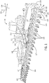
- Figures 1 and 2 illustrate a work vehicle 100 according to example embodiments of the present disclosure.
- the work vehicle 100 may be a planter or seeder configured for agricultural work. It will be appreciated that the illustrated work vehicle 100 is an example embodiment. One or more features of the present disclosure may be included on a different work vehicle without departing from the scope of the present disclosure.
- the work vehicle 100 may be towed by another vehicle, such as a tractor 101.
- the work vehicle 100 may be a towed work vehicle.
- the work vehicle 100 of the present disclosure may be a self-propelled vehicle.
- one or more features of the present disclosure may be applied to the tires of the tractor 101 shown in FIG. 1 .
- the work vehicle 100 includes a front end 114 and a rear end 116.
- the work vehicle 100 also includes a first side 120 and a second side 122.
- the work vehicle 100 defines a longitudinal axis 118, which may extend between the rear end 116 and the front end 114. It will be appreciated that the longitudinal axis 118 may correspond to a travel direction of the work vehicle 100.
- the work vehicle 100 further defines a lateral axis 124 extending between the first side 120 and the second side 122.
- the work vehicle 100 defines a vertical axis 126, which extends normal to the longitudinal axis 118 and the lateral axis 124.
- the work vehicle 100 may include a frame structure 110 (i.e., a chassis).
- the frame structure 110 may include an elongate tongue 111.
- the tongue 111 may be a rigid or telescoping beam that extends along the longitudinal axis 118.
- the tongue 111 may include a towing package for hitching and unhitching from the tractor 101.
- the frame structure 110 may further include a lateral beam 117.
- the lateral beam 117 may be a rigid member that extends along the lateral axis 124.
- the lateral beam 117 may be fixed to the tongue 111 of the frame structure 110, proximate the rear end 116 of the work vehicle 100.
- the work vehicle 100 may also include one or more commodity containers 128 that are supported on the frame structure 110.
- the commodity containers 128 may contain a bulk amount of a commodity (e.g., seed, fertilizer, etc.).
- the work vehicle 100 may further include a distribution system 133 with hoses, lines, etc. that are configured to distribute the commodity from the tank 131 to a plurality of row units 119.
- the commodity system 129 may also include a metering system that meters out the commodity at a predetermined rate.
- the work vehicle 100 may additionally include at least one ground support unit 210 configured for supporting movement of the work vehicle 100 across a field.
- the ground support unit 210 may be a continuous track 212.
- the track 212 may be supported for continuous movement relative to the frame structure 110.
- the track 212 may run in a loop and may continuously travel along the longitudinal axis 118 as the work vehicle 100 moves.
- the track 212 may be driven (e.g., by an electric motor, a hydraulic actuator, etc.) to propel the vehicle 100.
- the track 212 may move continuously due to the tractor 101 that is towing the work vehicle 100.
- the row units 119 may be attached to the lateral beam 117 of the frame structure 110.
- the row units 119 may branch rearward from the lateral beam 117 to define much of the rear end 116 of the work vehicle 100.
- the plurality of row units 119 may be substantially similar to each other and may include a first row unit 121, a second row unit 123, a third row unit 125, and so on, across the rear end 116 and along the lateral axis 124.
- the row units 119 may be configured to: 1) open a trench, furrow, or other ground opening as the work vehicle 100 moves through a field; 2) deposit seed, fertilizer, or other commodity within the opening; and 3) close the ground opening by moving soil and/or other materials back into the opening to thereby plant the commodity therein.
- the first row unit 121 may be a representative example of the other row units 119.
- the first row unit 121 may include a row unit frame 130.
- the row unit frame 130 may include a plurality of strong and rigid brackets, linkages, fasteners, etc., that support other components that will be discussed.
- the row unit frame 130 may be attached to the frame structure 110.
- the row unit frame 130 may be attached to the lateral beam 117 and may extend rearward therefrom.
- the first row unit 121 may also include a ground system 132.
- the ground system 112 may include one or more gauge wheels 134 that are attached to the row unit frame 130.
- the ground system 132 may also include one or more ground engaging implements 135 that move soil (e.g., to create and close a trench as the vehicle 100 moves across the field).
- the ground engaging implements 135 may include one or more opener implements 136 (e.g., opener discs or wheels) and one or more closer implements 138 (i.e., closer discs or wheels).
- the opener implements 136 may open a trench in the soil, seed may be deposited in the open trench, and the closer implements 138 may close the trench over the seed.
- the gauge wheels 134 may ride on the surface of the ground as the vehicle 100 travels, maintaining a set vertical position of the ground engaging implements 135 relative to the ground surface. Thus, the gauge wheels 134 may maintain a set depth of the furrow created by the opener implements 136 and maintain a consistent depth for the commodity within the earth.
- the commodity containers 128 may contain a substantial amount of the commodity.
- the one or more ground support units 210 may be configured for supporting this weight in a manner that promotes planting operations of the work vehicle 100 as represented in FIG. 2 .
- the continuous track 212 may be a first continuous track 212.
- the work vehicle 100 may also include a second continuous track 222.
- the first and second continuous tracks 212, 222 may be disposed on opposite lateral sides of the frame structure 110, proximate and generally underneath the commodity tanks 128.
- the first and second continuous tracks 212, 222 may be disposed proximate the central longitudinal axis 118 of the work vehicle 100.
- the first and second continuous tracks 212, 222 may include various features that effectively support the vehicle 100 for movement across the field. These features may limit compaction of the ground material as the vehicle 100 moves. These features may also maintain a smooth path, for example, for the gauge wheels 134 to traverse. Accordingly, these features enhance the effectiveness and efficiency of the row units 119.
- the first and second continuous tracks 212, 222 may be the only two ground support units 210 at this position along the axis 118 of the vehicle 100. Accordingly, distortion and/or compaction of the soil and other ground material with the work vehicle 100 may be minimized. Furthermore, the work vehicle 100 may be better equipped to travel over crowned roads, across a particular grade, etc.
- the first and second continuous tracks 212, 222 may be substantially similar.
- the first continuous track 212 will be discussed in detail, and this description may apply to the second continuous track 222.
- the first continuous track 212 may include a belt 230.
- the belt 230 may define an outer face 232 that alternatingly faces the ground and faces the sky as the vehicle 100 moves.
- the belt 230 may also define a first lateral side 234 (outer lateral side) and a second lateral side 236 (inner lateral side) that extend continuously on opposite sides of the belt 230.
- the first lateral side 234 may face outward away from the longitudinal axis 118 and the second lateral side 236 may face inward.
- a width of the belt 230 measured from the first lateral side 234 to the second lateral side 236 may be approximately twenty four inches (61 cm) or larger. This may ensure sufficient soil contact area to reduce compaction to an acceptable level.
- the outer face 232 may include a tread surface 240 with a first non-treaded area 242, a second non-treaded area 244, and a tread area 246 that are spaced apart laterally from each other.
- the first non-treaded area 242 may define the first lateral side 234.
- the second non-treaded area 244 may define the second lateral side 236.
- the tread area 246 may be disposed between the first non-treaded area 242 and the second non-treaded area 244 along the lateral axis 124.
- the tread area 246 may include a plurality of projections, such as bar treads 250 that project outwardly at a distance (i.e., a tread depth 252) from the surrounding areas of the outer face 232.
- the bar treads 250 may be disposed at a positive angle 254 relative to the longitudinal axis 118.
- There may be a first and second row of bar treads 250 arranged symmetrically within the tread area 246.
- the first non-treaded area 242 and the second non-treaded area 244 may be substantially smooth.
- the first and second smooth areas 242, 244 may be a flush, even area of the outer face 232.
- the first and second continuous tracks 212, 222 may distort (compress, squeeze, or otherwise move) the soil, mud, and other ground material to some degree.
- the effects may be minimized because the first and second continuous tracks 212, 222 are spaced outward laterally on the tread surface 240.
- the tracks 212, 222 may move the ground material outward laterally from the track 212, 222 instead of compacting downward.
- the tread area 246 may provide traction in some embodiments and may create divots, tread marks, or other distortions.
- the first non-treaded area 242 may leave the ground relatively smooth as it travels over.
- the second non-treaded area 244 may leave the opposite side relatively smooth as well.
- a fourth row unit 201, a fifth row unit 202, a sixth row unit 203, and a seventh row unit 204 are shown in the embodiment of FIG. 2 .
- These row units 201-204 may be substantially similar to the row units 119 discussed above with respect to FIG. 1 .
- the fourth and fifth row units 201, 202 may trail immediately behind the first continuous track 212.
- the sixth and seventh row units 203, 204 may trail immediately behind the second continuous track 212.
- the first non-treaded area 242 of the first continuous track 212 may be aligned longitudinally (along the travel direction) with the opener implement 136a, the gauge wheel 134a, and the closer implement 138a of the fourth row unit 201.
- the second non-treaded area 244 may be aligned longitudinally with the opener implement 136b, the gauge wheel 134b, and the closer implement 138b of the fifth row unit 202.
- the tread area 246 may be aligned longitudinally with an intermediate space 299 defined between the fourth row unit 201 and the fifth row unit 202.
- the second continuous track 222 may be similarly aligned with respect to the sixth and seventh row units 203, 204.
- the gauge wheels 134 of the row units 119 are likely to encounter smooth ground as the vehicle 100 travels across the field.
- the gauge wheels 134 are less likely to bounce vertically or vibrate during travel.
- the gauge wheels 134 are thereby better able to maintain the opener and closer implements 136, 138 at the set height such that the row unit 119 is more likely to plant the commodity at a predetermined soil depth.
- non-treaded portions 242, 244 of the tracks 212, 222 may be aligned with the opener and closer implements 136, 138.
- These implements 136, 138 are, therefore, more likely to encounter minimally compacted ground. Accordingly, the opener implements 136 and the closer implements 138 are better able to move the ground material and ensure proper planting of the commodity.
Landscapes
- Life Sciences & Earth Sciences (AREA)
- Soil Sciences (AREA)
- Environmental Sciences (AREA)
- Engineering & Computer Science (AREA)
- Mechanical Engineering (AREA)
- Guiding Agricultural Machines (AREA)
- Soil Working Implements (AREA)
- Agricultural Machines (AREA)
Claims (15)
- Arbeitsfahrzeug (10), das zum Fahren in einer Fahrtrichtung über eine Bodenfläche gestaltet ist, wobei das Arbeitsfahrzeug umfasst:einen Rahmen (110);eine Reiheneinheiten (119; 121, 123, 125), die an dem Rahmen angebracht ist, wobei die Reiheneinheit ein Messrad (134) und ein Bodeneingriffsgerät (135) beinhaltet, wobei das Messrad zum Laufen auf der Bodenfläche und zum Halten des Bodeneingriffsgeräts auf einer vorbestimmten vertikalen Position in Bezug auf die Bodenoberfläche gestaltet ist; undeine Bodenabstützungseinheit (210), die den Rahmen zur Bewegung über die Bodenfläche trägt, wobei die Bodenabstützungseinheit eine Außenfläche (232) beinhaltet, wobei die Außenfläche dadurch gekennzeichnet ist, dass sie einen profilfreien Seitenbereich (242, 244) beinhaltet, der eine seitliche Seite der Außenfläche definiert, wobei die Außenfläche einen Profilbereich (246) beinhaltet, der seitlich von der seitlichen Kante beabstandet ist, wobei der Profilbereich eine Vielzahl von Vorsprüngen (250) beinhaltet, wobei der profilfreie Seitenbereich entlang der Fahrtrichtung in Bezug auf das Messrad ausgerichtet ist.
- Arbeitsfahrzeug nach Anspruch 1, dadurch gekennzeichnet, dass die Bodenabstützungseinheit (210) eine Endloskette (212) ist.
- Arbeitsfahrzeug nach Anspruch 1 oder 2, dadurch gekennzeichnet, dass der profilfreie Seitenbereich entlang der Fahrtrichtung in Bezug auf das Bodeneingriffsgerät ausgerichtet ist.
- Arbeitsfahrzeug nach Anspruch 2 und 3, dadurch gekennzeichnet, dass die Reiheneinheit eine erste Reiheneinheit (121) mit einem ersten Messrad (134) und einem ersten Bodeneingriffsgerät ist, wobei das erste Messrad zum Laufen auf der Bodenfläche und zum Halten des ersten Bodeneingriffsgeräts an der vorbestimmten vertikalen Position in Bezug auf die Bodenfläche gestaltet ist;ferner umfassend eine zweite Reiheneinheit (123) mit einem zweiten Messrad und einem zweiten Bodeneingriffsgerät, wobei das zweite Messrad zum Laufen auf der Bodenfläche und zum Halten des zweiten Bodeneingriffsgeräts an der vorbestimmten vertikalen Position in Bezug auf die Bodenfläche gestaltet ist;ferner umfassend einen Zwischenraum, der seitlich zwischen der ersten und der zweiten Reiheneinheit definiert ist,wobei die Endloskette (212) einen ersten profilfreien Seitenbereich (242, 244), der eine erste seitliche Seite der Außenfläche definiert, einen zweiten profilfreien Seitenbereich, der eine zweite seitliche Seite der Außenfläche definiert, und den Profilbereich beinhaltet;wobei der Profilbereich (246) zwischen dem ersten und dem zweiten profilfreien Seitenbereich definiert ist, wobei der Profilbereich eine Vielzahl von Profilelementen (250) beinhaltet, wobei der erste profilfreie Seitenbereich entlang der Fahrtrichtung in Bezug auf das erste Messrad (134) und das erste Bodeneingriffsgerät ausgerichtet ist, wobei der zweite profilfreie Seitenbereich entlang der Fahrtrichtung in Bezug auf das zweite Messrad und das zweite Bodeneingriffsgerät ausgerichtet ist, wobei der Profilbereich entlang der Fahrtrichtung in Bezug auf den Zwischenraum ausgerichtet ist.
- Arbeitsfahrzeug nach einem der vorhergehenden Ansprüche, dadurch gekennzeichnet, dass die Vielzahl von Vorsprüngen (250) eine Vielzahl von riegelförmigen Profilelementen beinhaltet, die sich in einem positiven Winkel (254) relativ zur Fahrtrichtung erstrecken.
- Arbeitsfahrzeug nach einem der vorhergehenden Ansprüche, dadurch gekennzeichnet, dass das Bodeneingriffsgerät ein Öffnergerät (136a), gestaltet zum Öffnen einer Furche, während das Arbeitsfahrzeug über das Feld fährt, beinhaltet;
wobei der profilfreie Seitenbereich entlang der Fahrtrichtung in Bezug auf das Messrad und das Öffnergerät ausgerichtet ist. - Arbeitsfahrzeug nach einem der vorhergehenden Ansprüche, dadurch gekennzeichnet, dass das Bodeneingriffsgerät ein Schließergerät (138a), gestaltet zum Schließen einer Furche, während das Arbeitsfahrzeug über das Feld fährt, beinhaltet;
wobei der profilfreie Seitenbereich entlang der Fahrtrichtung in Bezug auf das Messrad und das Schließergerät ausgerichtet ist. - Arbeitsfahrzeug nach einem der Ansprüche 1 bis 5, dadurch gekennzeichnet, dass das Bodeneingriffsgerät ein Öffnergerät, gestaltet zum Öffnen einer Furche, und ein Schließergerät, gestaltet zum Schließen der Furche, während das Arbeitsfahrzeug über das Feld fährt, beinhaltet; und
wobei der profilfreie Seitenbereich entlang der Fahrtrichtung in Bezug auf das Messrad, das Öffnergerät und das Schließergerät ausgerichtet ist. - Arbeitsfahrzeug nach einem der vorhergehenden Ansprüche, dadurch gekennzeichnet, dass das Arbeitsfahrzeug ein Anhängerkupplungssystem zum Anhängen des Arbeitsfahrzeugs an ein Zugfahrzeug beinhaltet.
- Arbeitsfahrzeug, das zum Fahren in einer Fahrtrichtung über eine Bodenfläche gestaltet ist, wobei das Arbeitsfahrzeug umfasst:einen Gebrauchsgutbehälter (128), der zum Enthalten eines Gebrauchsguts gestaltet ist;einen Rahmen (110), der den Gebrauchsgutbehälter trägt;ein Abgabesystem (133), das von dem Rahmen getragen wird und zum Befördern des Gebrauchsguts aus dem Gebrauchsgutbehälter vom Arbeitsfahrzeug weg gestaltet ist;eine Reiheneinheit (119), die an dem Rahmen angebracht ist und ein Messrad (40) und ein Bodeneingriffsgerät beinhaltet, wobei das Messrad zum Laufen auf der Bodenfläche und zum Halten des Bodeneingriffsgeräts auf einer vorbestimmten vertikalen Position in Bezug auf die Bodenfläche gestaltet ist; und gekennzeichnet durcheine Bodenabstützungseinheit (210), die den Rahmen zur Bewegung über die Bodenfläche trägt, wobei die Bodenabstützungseinheit eine Außenfläche beinhaltet, wobei die Außenfläche einen profilfreien Seitenbereich beinhaltet, der eine seitliche Seite der Außenfläche definiert, wobei die Außenfläche einen Profilbereich beinhaltet, der seitlich von der seitlichen Kante beabstandet ist, wobei der Profilbereich eine Vielzahl von Vorsprüngen beinhaltet, wobei der profilfreie Seitenbereich entlang der Fahrtrichtung in Bezug auf das Messrad ausgerichtet ist.
- Arbeitsfahrzeug nach Anspruch 10, dadurch gekennzeichnet, dass die Bodenabstützungseinheit eine Endloskette ist;wobei der profilfreie Seitenbereich entlang der Fahrtrichtung in Bezug auf das Bodeneingriffsgerät ausgerichtet ist; undwobei die Reiheneinheit eine erste Reiheneinheit mit einem ersten Messrad und einem ersten Bodeneingriffsgerät ist, wobei das erste Messrad zum Laufen auf der Bodenfläche und zum Halten des ersten Bodeneingriffsgeräts an der vorbestimmten vertikalen Position in Bezug auf die Bodenfläche gestaltet ist;ferner umfassend eine zweite Reiheneinheit mit einem zweiten Messrad und einem zweiten Bodeneingriffsgerät, wobei das zweite Messrad zum Laufen auf der Bodenfläche und zum Halten des zweiten Bodeneingriffsgeräts an der vorbestimmten vertikalen Position in Bezug auf die Bodenfläche gestaltet ist;ferner umfassend einen Zwischenraum, der seitlich zwischen der ersten und der zweiten Reiheneinheit definiert ist,wobei die Endloskette einen ersten profilfreien Seitenbereich, der eine erste seitliche Seite der Außenfläche definiert, einen zweiten profilfreien Seitenbereich, der eine zweite seitliche Seite der Außenfläche definiert, und den Profilbereich beinhaltet;wobei der Profilbereich zwischen dem ersten und dem zweiten profilfreien Seitenbereich definiert ist, wobei der Profilbereich eine Vielzahl von Profilelementen beinhaltet, wobei der erste profilfreie Seitenbereich entlang der Fahrtrichtung in Bezug auf das erste Messrad und das erste Bodeneingriffsgerät ausgerichtet ist, wobei der zweite profilfreie Seitenbereich entlang der Fahrtrichtung in Bezug auf das zweite Messrad und das zweite Bodeneingriffsgerät ausgerichtet ist, wobei der Profilbereich entlang der Fahrtrichtung in Bezug auf den Zwischenraum ausgerichtet ist.
- Arbeitsfahrzeug nach Anspruch 10 oder 11, dadurch gekennzeichnet, dass die Vielzahl von Vorsprüngen eine Vielzahl von riegelförmigen Profilelementen (250) beinhaltet, die sich in einem positiven Winkel (254) relativ zur Fahrtrichtung erstrecken.
- Arbeitsfahrzeug nach Anspruch 10, 11 oder 12, dadurch gekennzeichnet, dass das Bodeneingriffsgerät ein Öffnergerät (136a), gestaltet zum Öffnen einer Furche, während das Arbeitsfahrzeug über das Feld fährt, und/oder ein Schließergerät (138a), gestaltet zum Schließen einer Furche, während das Arbeitsfahrzeug über das Feld fährt, beinhaltet;
wobei der profilfreie Seitenbereich entlang der Fahrtrichtung in Bezug auf das Messrad und das Öffnergerät oder das Schließergerät ausgerichtet ist. - Arbeitsfahrzeug (100), das zum Fahren in einer Fahrtrichtung über eine Bodenfläche gestaltet ist, wobei das Arbeitsfahrzeug umfasst:einen Rahmen (110);eine Vielzahl von Reiheneinheiten (119), die an dem Rahmen angebracht sind, wobei die Vielzahl von Reiheneinheiten eine erste Reiheneinheit und eine zweite Reiheneinheit beinhaltet, wobei die erste Reiheneinheit mit einem seitlich zwischen der ersten und der zweiten Reiheneinheit definierten Zwischenraum an die zweite Reiheneinheit angrenzt, wobei die erste Reiheneinheit ein erstes Messrad (134) und ein erstes Bodeneingriffsgerät (135) beinhaltet, wobei die zweite Reiheneinheit ein zweites Messrad und ein zweites Bodeneingriffsgerät beinhaltet; undeine Bodenabstützungseinheit (210), die den Rahmen zur Bewegung über die Bodenfläche trägt, wobei die Fahrzeugabstützung eine Endloslauffläche beinhaltet, wobei die Endloslauffläche einen ersten profilfreien Seitenbereich, der eine erste seitliche Seite der Endloslauffläche definiert, einen zweiten profilfreien Seitenbereich, der eine zweite seitliche Seite der Endloslauffläche definiert, und einen Profilbereich, der zwischen dem ersten und dem zweiten profilfreien Bereich definiert ist, beinhaltet, wobei der Profilbereich eine Vielzahl von Profilelementen beinhaltet, wobei der erste profilfreie Seitenbereich entlang der Fahrtrichtung in Bezug auf das erste Messrad und das erste Bodeneingriffsgerät ausgerichtet ist, der zweite profilfreie Seitenbereich entlang der Fahrtrichtung in Bezug auf das zweite Messrad und das zweite Bodeneingriffsgerät ausgerichtet ist, der Zwischenbereich mit Profil entlang der Fahrtrichtung in Bezug auf den Zwischenraum ausgerichtet ist.
- Arbeitsfahrzeug nach Anspruch 14, dadurch gekennzeichnet, dass die erste Reiheneinheit das erste Messrad, ein erstes Öffnergerät und ein erstes Schließergerät beinhaltet;wobei die zweite Reiheneinheit ein zweites Messrad, ein zweites Öffnergerät und ein zweites Schließergerät beinhaltet;wobei der erste profilfreie Seitenbereich entlang der Fahrtrichtung in Bezug auf das erste Messrad, das erste Öffnergerät und das erste Schließergerät ausgerichtet ist; undwobei der zweite profilfreie Seitenbereich entlang der Fahrtrichtung in Bezug auf das zweite Messrad, das zweite Öffnergerät und das zweite Schließergerät ausgerichtet ist, und das zweite Schließergerät.
Applications Claiming Priority (1)
| Application Number | Priority Date | Filing Date | Title |
|---|---|---|---|
| US16/057,407 US11665990B2 (en) | 2018-08-07 | 2018-08-07 | Work vehicle with ground support unit having non-treaded area aligned with row unit component |
Publications (2)
| Publication Number | Publication Date |
|---|---|
| EP3607809A1 EP3607809A1 (de) | 2020-02-12 |
| EP3607809B1 true EP3607809B1 (de) | 2021-12-08 |
Family
ID=67070676
Family Applications (1)
| Application Number | Title | Priority Date | Filing Date |
|---|---|---|---|
| EP19182401.0A Active EP3607809B1 (de) | 2018-08-07 | 2019-06-25 | Arbeitsfahrzeug mit gegenüber einer reihenbearbeitungseinheit ausgerichtetem profilfreiem bereich einer bodenabstützung |
Country Status (5)
| Country | Link |
|---|---|
| US (1) | US11665990B2 (de) |
| EP (1) | EP3607809B1 (de) |
| AR (1) | AR115669A1 (de) |
| AU (1) | AU2019204779B2 (de) |
| CA (1) | CA3047869A1 (de) |
Families Citing this family (3)
| Publication number | Priority date | Publication date | Assignee | Title |
|---|---|---|---|---|
| CN112075167A (zh) * | 2020-07-31 | 2020-12-15 | 昆明理工大学 | 一种人参精密播种机 |
| DE102020123214A1 (de) | 2020-09-04 | 2022-03-10 | Lemken Gmbh & Co. Kg | Bodenbearbeitungsgerät |
| SE2150871A1 (en) * | 2021-07-05 | 2022-12-06 | Vaederstad Holding Ab | Down force control and method for down force control in an agricultural implement |
Family Cites Families (20)
| Publication number | Priority date | Publication date | Assignee | Title |
|---|---|---|---|---|
| US1522448A (en) * | 1922-10-16 | 1925-01-06 | Harig Carl | Tire |
| US2130524A (en) * | 1936-07-08 | 1938-09-20 | Ciark Ernest | Nonskid tire |
| US3037469A (en) * | 1960-05-23 | 1962-06-05 | Norman E Watson | Minimum tillage planter |
| US3372657A (en) * | 1964-04-06 | 1968-03-12 | Deere & Co | Minimum tillage apparatus |
| FR2382348A1 (fr) * | 1977-03-03 | 1978-09-29 | Michelin & Cie | Bande de roulement d'enveloppe de pneumatique |
| IT1134617B (it) * | 1980-12-05 | 1986-08-13 | Pirelli | Pneumatico per autoveicoli con disegno ad elevati doti comportamentali e bassa rumorosita' |
| US5097882A (en) * | 1988-07-11 | 1992-03-24 | The Goodyear Tire & Rubber Company | Tire tread and tire including trapezoidal block elements nested in reentrant angles of zigzag ribs |
| USD460403S1 (en) * | 2000-11-08 | 2002-07-16 | Michelin Recherche Et Technique S.A. | Tire tread |
| USD482319S1 (en) * | 2002-11-15 | 2003-11-18 | The Goodyear Tire & Rubber Company | Tire tread |
| USD505655S1 (en) * | 2004-02-09 | 2005-05-31 | The Goodyear Tire & Rubber Company | Center tread for motorcycle tire |
| US7231948B2 (en) * | 2004-03-18 | 2007-06-19 | Carlisle Intangible Company | Non-pneumatic tire |
| BRPI0722196C8 (pt) * | 2007-11-06 | 2019-08-13 | Pirelli | pneu para motocicletas, e, motocicleta |
| US8428831B2 (en) * | 2008-05-01 | 2013-04-23 | Cnh Canada, Ltd. | Automatic steering system for an agricultural implement |
| US8281831B2 (en) * | 2009-01-05 | 2012-10-09 | Tsai Jen Lo | Asymmetric pattern tread for ATV tire |
| IT1395004B1 (it) * | 2009-07-28 | 2012-08-07 | Pirelli | Coppia di pneumatici per motoveicoli. |
| US8700269B2 (en) | 2011-03-08 | 2014-04-15 | Great Plains Manufacturing, Inc. | Steerable agricultural implement with multi-point hitch |
| US9096264B2 (en) | 2013-03-14 | 2015-08-04 | Cnh Industrial America Llc | Implement carrier with steerable tracks |
| US9699949B2 (en) | 2014-02-11 | 2017-07-11 | NORWOOD SALES, Inc. | Wing positioning apparatus |
| US20160050837A1 (en) * | 2014-08-25 | 2016-02-25 | Schaffert Manufacturing Company, Inc. | Trailing arm device and assembly with parallel linkage |
| USD766164S1 (en) * | 2015-01-08 | 2016-09-13 | Cheng Shin Rubber (Xiamen) Ind., Ltd | Tire |
-
2018
- 2018-08-07 US US16/057,407 patent/US11665990B2/en active Active
-
2019
- 2019-06-25 EP EP19182401.0A patent/EP3607809B1/de active Active
- 2019-06-26 CA CA3047869A patent/CA3047869A1/en active Pending
- 2019-07-01 AR ARP190101849A patent/AR115669A1/es active IP Right Grant
- 2019-07-03 AU AU2019204779A patent/AU2019204779B2/en active Active
Also Published As
| Publication number | Publication date |
|---|---|
| AR115669A1 (es) | 2021-02-10 |
| AU2019204779A1 (en) | 2020-02-27 |
| US11665990B2 (en) | 2023-06-06 |
| EP3607809A1 (de) | 2020-02-12 |
| AU2019204779B2 (en) | 2025-05-29 |
| BR102019013943A2 (pt) | 2020-02-11 |
| US20200045872A1 (en) | 2020-02-13 |
| CA3047869A1 (en) | 2020-02-07 |
Similar Documents
| Publication | Publication Date | Title |
|---|---|---|
| US8356563B2 (en) | Seed planter with equalizer assembly | |
| US10729054B2 (en) | Tracked agricultural implement having a caster wheel assembly | |
| AU2019204779B2 (en) | Work vehicle with ground support unit having non-treaded area aligned with row unit component | |
| CA2666909C (en) | Apparatus for controlling the placement of seeds within a furrow | |
| CA2838531C (en) | Implement carrier with steerable tracks | |
| US10137951B2 (en) | Steerable trailer | |
| US9820425B2 (en) | Gauge wheel arrangement for a seeder row unit | |
| US12256661B2 (en) | Systems, methods, and apparatus for agricultural material application | |
| US6213034B1 (en) | Planter apparatus and method | |
| CA1251997A (en) | Zero-till drill | |
| US10798864B2 (en) | Row unit for work vehicle having gauge wheel with adjustable lateral position | |
| US6386792B1 (en) | Implement for filling wheel tracks | |
| CN104427855A (zh) | 具有改良型机架的农业机械 | |
| US3083652A (en) | Earth conditioning and seeding trailer | |
| US20260041030A1 (en) | Agricultural Implements and Related Methods | |
| US11711996B2 (en) | High speed agricultural seeder | |
| BR102019013943B1 (pt) | Veículo de trabalho configurado para se deslocar em uma direção de deslocamento através de uma superfície de solo | |
| WO2007094730A1 (en) | Agricultural machine | |
| US20170049038A1 (en) | Farm implement for tilling soil | |
| US8567326B2 (en) | Secondary air seeder assembly and system using the same | |
| BR102025009691A2 (pt) | Implementos agrícolas e métodos relacionados | |
| NL2009737C2 (en) | Variable track width wheel suspension for an agricultural vehicle and vehicle with such a suspension. | |
| JPH07284313A (ja) | 多条苗植機 |
Legal Events
| Date | Code | Title | Description |
|---|---|---|---|
| PUAI | Public reference made under article 153(3) epc to a published international application that has entered the european phase |
Free format text: ORIGINAL CODE: 0009012 |
|
| STAA | Information on the status of an ep patent application or granted ep patent |
Free format text: STATUS: THE APPLICATION HAS BEEN PUBLISHED |
|
| AK | Designated contracting states |
Kind code of ref document: A1 Designated state(s): AL AT BE BG CH CY CZ DE DK EE ES FI FR GB GR HR HU IE IS IT LI LT LU LV MC MK MT NL NO PL PT RO RS SE SI SK SM TR |
|
| AX | Request for extension of the european patent |
Extension state: BA ME |
|
| STAA | Information on the status of an ep patent application or granted ep patent |
Free format text: STATUS: REQUEST FOR EXAMINATION WAS MADE |
|
| 17P | Request for examination filed |
Effective date: 20200812 |
|
| RBV | Designated contracting states (corrected) |
Designated state(s): AL AT BE BG CH CY CZ DE DK EE ES FI FR GB GR HR HU IE IS IT LI LT LU LV MC MK MT NL NO PL PT RO RS SE SI SK SM TR |
|
| GRAP | Despatch of communication of intention to grant a patent |
Free format text: ORIGINAL CODE: EPIDOSNIGR1 |
|
| STAA | Information on the status of an ep patent application or granted ep patent |
Free format text: STATUS: GRANT OF PATENT IS INTENDED |
|
| INTG | Intention to grant announced |
Effective date: 20210927 |
|
| GRAS | Grant fee paid |
Free format text: ORIGINAL CODE: EPIDOSNIGR3 |
|
| GRAA | (expected) grant |
Free format text: ORIGINAL CODE: 0009210 |
|
| STAA | Information on the status of an ep patent application or granted ep patent |
Free format text: STATUS: THE PATENT HAS BEEN GRANTED |
|
| AK | Designated contracting states |
Kind code of ref document: B1 Designated state(s): AL AT BE BG CH CY CZ DE DK EE ES FI FR GB GR HR HU IE IS IT LI LT LU LV MC MK MT NL NO PL PT RO RS SE SI SK SM TR |
|
| REG | Reference to a national code |
Ref country code: GB Ref legal event code: FG4D |
|
| REG | Reference to a national code |
Ref country code: AT Ref legal event code: REF Ref document number: 1453021 Country of ref document: AT Kind code of ref document: T Effective date: 20211215 Ref country code: CH Ref legal event code: EP |
|
| REG | Reference to a national code |
Ref country code: DE Ref legal event code: R096 Ref document number: 602019009828 Country of ref document: DE |
|
| REG | Reference to a national code |
Ref country code: IE Ref legal event code: FG4D |
|
| REG | Reference to a national code |
Ref country code: LT Ref legal event code: MG9D |
|
| REG | Reference to a national code |
Ref country code: NL Ref legal event code: MP Effective date: 20211208 |
|
| PG25 | Lapsed in a contracting state [announced via postgrant information from national office to epo] |
Ref country code: RS Free format text: LAPSE BECAUSE OF FAILURE TO SUBMIT A TRANSLATION OF THE DESCRIPTION OR TO PAY THE FEE WITHIN THE PRESCRIBED TIME-LIMIT Effective date: 20211208 Ref country code: LT Free format text: LAPSE BECAUSE OF FAILURE TO SUBMIT A TRANSLATION OF THE DESCRIPTION OR TO PAY THE FEE WITHIN THE PRESCRIBED TIME-LIMIT Effective date: 20211208 Ref country code: FI Free format text: LAPSE BECAUSE OF FAILURE TO SUBMIT A TRANSLATION OF THE DESCRIPTION OR TO PAY THE FEE WITHIN THE PRESCRIBED TIME-LIMIT Effective date: 20211208 Ref country code: BG Free format text: LAPSE BECAUSE OF FAILURE TO SUBMIT A TRANSLATION OF THE DESCRIPTION OR TO PAY THE FEE WITHIN THE PRESCRIBED TIME-LIMIT Effective date: 20220308 |
|
| REG | Reference to a national code |
Ref country code: AT Ref legal event code: MK05 Ref document number: 1453021 Country of ref document: AT Kind code of ref document: T Effective date: 20211208 |
|
| PG25 | Lapsed in a contracting state [announced via postgrant information from national office to epo] |
Ref country code: SE Free format text: LAPSE BECAUSE OF FAILURE TO SUBMIT A TRANSLATION OF THE DESCRIPTION OR TO PAY THE FEE WITHIN THE PRESCRIBED TIME-LIMIT Effective date: 20211208 Ref country code: NO Free format text: LAPSE BECAUSE OF FAILURE TO SUBMIT A TRANSLATION OF THE DESCRIPTION OR TO PAY THE FEE WITHIN THE PRESCRIBED TIME-LIMIT Effective date: 20220308 Ref country code: LV Free format text: LAPSE BECAUSE OF FAILURE TO SUBMIT A TRANSLATION OF THE DESCRIPTION OR TO PAY THE FEE WITHIN THE PRESCRIBED TIME-LIMIT Effective date: 20211208 Ref country code: HR Free format text: LAPSE BECAUSE OF FAILURE TO SUBMIT A TRANSLATION OF THE DESCRIPTION OR TO PAY THE FEE WITHIN THE PRESCRIBED TIME-LIMIT Effective date: 20211208 Ref country code: GR Free format text: LAPSE BECAUSE OF FAILURE TO SUBMIT A TRANSLATION OF THE DESCRIPTION OR TO PAY THE FEE WITHIN THE PRESCRIBED TIME-LIMIT Effective date: 20220309 Ref country code: ES Free format text: LAPSE BECAUSE OF FAILURE TO SUBMIT A TRANSLATION OF THE DESCRIPTION OR TO PAY THE FEE WITHIN THE PRESCRIBED TIME-LIMIT Effective date: 20211208 |
|
| PG25 | Lapsed in a contracting state [announced via postgrant information from national office to epo] |
Ref country code: NL Free format text: LAPSE BECAUSE OF FAILURE TO SUBMIT A TRANSLATION OF THE DESCRIPTION OR TO PAY THE FEE WITHIN THE PRESCRIBED TIME-LIMIT Effective date: 20211208 |
|
| PG25 | Lapsed in a contracting state [announced via postgrant information from national office to epo] |
Ref country code: SM Free format text: LAPSE BECAUSE OF FAILURE TO SUBMIT A TRANSLATION OF THE DESCRIPTION OR TO PAY THE FEE WITHIN THE PRESCRIBED TIME-LIMIT Effective date: 20211208 Ref country code: SK Free format text: LAPSE BECAUSE OF FAILURE TO SUBMIT A TRANSLATION OF THE DESCRIPTION OR TO PAY THE FEE WITHIN THE PRESCRIBED TIME-LIMIT Effective date: 20211208 Ref country code: RO Free format text: LAPSE BECAUSE OF FAILURE TO SUBMIT A TRANSLATION OF THE DESCRIPTION OR TO PAY THE FEE WITHIN THE PRESCRIBED TIME-LIMIT Effective date: 20211208 Ref country code: PT Free format text: LAPSE BECAUSE OF FAILURE TO SUBMIT A TRANSLATION OF THE DESCRIPTION OR TO PAY THE FEE WITHIN THE PRESCRIBED TIME-LIMIT Effective date: 20220408 Ref country code: EE Free format text: LAPSE BECAUSE OF FAILURE TO SUBMIT A TRANSLATION OF THE DESCRIPTION OR TO PAY THE FEE WITHIN THE PRESCRIBED TIME-LIMIT Effective date: 20211208 Ref country code: CZ Free format text: LAPSE BECAUSE OF FAILURE TO SUBMIT A TRANSLATION OF THE DESCRIPTION OR TO PAY THE FEE WITHIN THE PRESCRIBED TIME-LIMIT Effective date: 20211208 |
|
| PG25 | Lapsed in a contracting state [announced via postgrant information from national office to epo] |
Ref country code: PL Free format text: LAPSE BECAUSE OF FAILURE TO SUBMIT A TRANSLATION OF THE DESCRIPTION OR TO PAY THE FEE WITHIN THE PRESCRIBED TIME-LIMIT Effective date: 20211208 Ref country code: AT Free format text: LAPSE BECAUSE OF FAILURE TO SUBMIT A TRANSLATION OF THE DESCRIPTION OR TO PAY THE FEE WITHIN THE PRESCRIBED TIME-LIMIT Effective date: 20211208 |
|
| REG | Reference to a national code |
Ref country code: DE Ref legal event code: R097 Ref document number: 602019009828 Country of ref document: DE |
|
| PG25 | Lapsed in a contracting state [announced via postgrant information from national office to epo] |
Ref country code: IS Free format text: LAPSE BECAUSE OF FAILURE TO SUBMIT A TRANSLATION OF THE DESCRIPTION OR TO PAY THE FEE WITHIN THE PRESCRIBED TIME-LIMIT Effective date: 20220408 |
|
| PLBE | No opposition filed within time limit |
Free format text: ORIGINAL CODE: 0009261 |
|
| STAA | Information on the status of an ep patent application or granted ep patent |
Free format text: STATUS: NO OPPOSITION FILED WITHIN TIME LIMIT |
|
| PG25 | Lapsed in a contracting state [announced via postgrant information from national office to epo] |
Ref country code: DK Free format text: LAPSE BECAUSE OF FAILURE TO SUBMIT A TRANSLATION OF THE DESCRIPTION OR TO PAY THE FEE WITHIN THE PRESCRIBED TIME-LIMIT Effective date: 20211208 Ref country code: AL Free format text: LAPSE BECAUSE OF FAILURE TO SUBMIT A TRANSLATION OF THE DESCRIPTION OR TO PAY THE FEE WITHIN THE PRESCRIBED TIME-LIMIT Effective date: 20211208 |
|
| 26N | No opposition filed |
Effective date: 20220909 |
|
| PG25 | Lapsed in a contracting state [announced via postgrant information from national office to epo] |
Ref country code: SI Free format text: LAPSE BECAUSE OF FAILURE TO SUBMIT A TRANSLATION OF THE DESCRIPTION OR TO PAY THE FEE WITHIN THE PRESCRIBED TIME-LIMIT Effective date: 20211208 |
|
| PG25 | Lapsed in a contracting state [announced via postgrant information from national office to epo] |
Ref country code: MC Free format text: LAPSE BECAUSE OF FAILURE TO SUBMIT A TRANSLATION OF THE DESCRIPTION OR TO PAY THE FEE WITHIN THE PRESCRIBED TIME-LIMIT Effective date: 20211208 |
|
| REG | Reference to a national code |
Ref country code: CH Ref legal event code: PL |
|
| REG | Reference to a national code |
Ref country code: BE Ref legal event code: MM Effective date: 20220630 |
|
| PG25 | Lapsed in a contracting state [announced via postgrant information from national office to epo] |
Ref country code: LU Free format text: LAPSE BECAUSE OF NON-PAYMENT OF DUE FEES Effective date: 20220625 Ref country code: LI Free format text: LAPSE BECAUSE OF NON-PAYMENT OF DUE FEES Effective date: 20220630 Ref country code: IE Free format text: LAPSE BECAUSE OF NON-PAYMENT OF DUE FEES Effective date: 20220625 Ref country code: CH Free format text: LAPSE BECAUSE OF NON-PAYMENT OF DUE FEES Effective date: 20220630 |
|
| PG25 | Lapsed in a contracting state [announced via postgrant information from national office to epo] |
Ref country code: IT Free format text: LAPSE BECAUSE OF FAILURE TO SUBMIT A TRANSLATION OF THE DESCRIPTION OR TO PAY THE FEE WITHIN THE PRESCRIBED TIME-LIMIT Effective date: 20211208 Ref country code: BE Free format text: LAPSE BECAUSE OF NON-PAYMENT OF DUE FEES Effective date: 20220630 |
|
| GBPC | Gb: european patent ceased through non-payment of renewal fee |
Effective date: 20230625 |
|
| PG25 | Lapsed in a contracting state [announced via postgrant information from national office to epo] |
Ref country code: MK Free format text: LAPSE BECAUSE OF FAILURE TO SUBMIT A TRANSLATION OF THE DESCRIPTION OR TO PAY THE FEE WITHIN THE PRESCRIBED TIME-LIMIT Effective date: 20211208 Ref country code: CY Free format text: LAPSE BECAUSE OF FAILURE TO SUBMIT A TRANSLATION OF THE DESCRIPTION OR TO PAY THE FEE WITHIN THE PRESCRIBED TIME-LIMIT Effective date: 20211208 Ref country code: GB Free format text: LAPSE BECAUSE OF NON-PAYMENT OF DUE FEES Effective date: 20230625 |
|
| PG25 | Lapsed in a contracting state [announced via postgrant information from national office to epo] |
Ref country code: HU Free format text: LAPSE BECAUSE OF FAILURE TO SUBMIT A TRANSLATION OF THE DESCRIPTION OR TO PAY THE FEE WITHIN THE PRESCRIBED TIME-LIMIT; INVALID AB INITIO Effective date: 20190625 |
|
| PG25 | Lapsed in a contracting state [announced via postgrant information from national office to epo] |
Ref country code: MT Free format text: LAPSE BECAUSE OF FAILURE TO SUBMIT A TRANSLATION OF THE DESCRIPTION OR TO PAY THE FEE WITHIN THE PRESCRIBED TIME-LIMIT Effective date: 20211208 |
|
| PGFP | Annual fee paid to national office [announced via postgrant information from national office to epo] |
Ref country code: DE Payment date: 20250521 Year of fee payment: 7 |
|
| PGFP | Annual fee paid to national office [announced via postgrant information from national office to epo] |
Ref country code: FR Payment date: 20250625 Year of fee payment: 7 |
|
| PG25 | Lapsed in a contracting state [announced via postgrant information from national office to epo] |
Ref country code: TR Free format text: LAPSE BECAUSE OF FAILURE TO SUBMIT A TRANSLATION OF THE DESCRIPTION OR TO PAY THE FEE WITHIN THE PRESCRIBED TIME-LIMIT Effective date: 20211208 |