EP3607744B1 - Tiefenbestimmung bei einer stereokamera mit hardwarebeschleuniger - Google Patents
Tiefenbestimmung bei einer stereokamera mit hardwarebeschleuniger Download PDFInfo
- Publication number
- EP3607744B1 EP3607744B1 EP17933955.1A EP17933955A EP3607744B1 EP 3607744 B1 EP3607744 B1 EP 3607744B1 EP 17933955 A EP17933955 A EP 17933955A EP 3607744 B1 EP3607744 B1 EP 3607744B1
- Authority
- EP
- European Patent Office
- Prior art keywords
- neural network
- hardware accelerator
- data
- bit representation
- accelerator component
- Prior art date
- Legal status (The legal status is an assumption and is not a legal conclusion. Google has not performed a legal analysis and makes no representation as to the accuracy of the status listed.)
- Active
Links
Images


Classifications
-
- G—PHYSICS
- G06—COMPUTING OR CALCULATING; COUNTING
- G06T—IMAGE DATA PROCESSING OR GENERATION, IN GENERAL
- G06T7/00—Image analysis
- G06T7/50—Depth or shape recovery
- G06T7/55—Depth or shape recovery from multiple images
-
- G—PHYSICS
- G06—COMPUTING OR CALCULATING; COUNTING
- G06T—IMAGE DATA PROCESSING OR GENERATION, IN GENERAL
- G06T7/00—Image analysis
- G06T7/50—Depth or shape recovery
- G06T7/55—Depth or shape recovery from multiple images
- G06T7/593—Depth or shape recovery from multiple images from stereo images
-
- G—PHYSICS
- G06—COMPUTING OR CALCULATING; COUNTING
- G06F—ELECTRIC DIGITAL DATA PROCESSING
- G06F9/00—Arrangements for program control, e.g. control units
- G06F9/06—Arrangements for program control, e.g. control units using stored programs, i.e. using an internal store of processing equipment to receive or retain programs
- G06F9/30—Arrangements for executing machine instructions, e.g. instruction decode
- G06F9/30003—Arrangements for executing specific machine instructions
- G06F9/30007—Arrangements for executing specific machine instructions to perform operations on data operands
- G06F9/30025—Format conversion instructions, e.g. Floating-Point to Integer, decimal conversion
-
- G—PHYSICS
- G06—COMPUTING OR CALCULATING; COUNTING
- G06F—ELECTRIC DIGITAL DATA PROCESSING
- G06F9/00—Arrangements for program control, e.g. control units
- G06F9/06—Arrangements for program control, e.g. control units using stored programs, i.e. using an internal store of processing equipment to receive or retain programs
- G06F9/46—Multiprogramming arrangements
- G06F9/50—Allocation of resources, e.g. of the central processing unit [CPU]
- G06F9/5005—Allocation of resources, e.g. of the central processing unit [CPU] to service a request
- G06F9/5027—Allocation of resources, e.g. of the central processing unit [CPU] to service a request the resource being a machine, e.g. CPUs, Servers, Terminals
-
- G—PHYSICS
- G06—COMPUTING OR CALCULATING; COUNTING
- G06N—COMPUTING ARRANGEMENTS BASED ON SPECIFIC COMPUTATIONAL MODELS
- G06N20/00—Machine learning
-
- G—PHYSICS
- G06—COMPUTING OR CALCULATING; COUNTING
- G06N—COMPUTING ARRANGEMENTS BASED ON SPECIFIC COMPUTATIONAL MODELS
- G06N3/00—Computing arrangements based on biological models
- G06N3/02—Neural networks
- G06N3/04—Architecture, e.g. interconnection topology
- G06N3/045—Combinations of networks
-
- G—PHYSICS
- G06—COMPUTING OR CALCULATING; COUNTING
- G06N—COMPUTING ARRANGEMENTS BASED ON SPECIFIC COMPUTATIONAL MODELS
- G06N3/00—Computing arrangements based on biological models
- G06N3/02—Neural networks
- G06N3/04—Architecture, e.g. interconnection topology
- G06N3/0464—Convolutional networks [CNN, ConvNet]
-
- G—PHYSICS
- G06—COMPUTING OR CALCULATING; COUNTING
- G06N—COMPUTING ARRANGEMENTS BASED ON SPECIFIC COMPUTATIONAL MODELS
- G06N3/00—Computing arrangements based on biological models
- G06N3/02—Neural networks
- G06N3/04—Architecture, e.g. interconnection topology
- G06N3/048—Activation functions
-
- G—PHYSICS
- G06—COMPUTING OR CALCULATING; COUNTING
- G06N—COMPUTING ARRANGEMENTS BASED ON SPECIFIC COMPUTATIONAL MODELS
- G06N3/00—Computing arrangements based on biological models
- G06N3/02—Neural networks
- G06N3/04—Architecture, e.g. interconnection topology
- G06N3/0495—Quantised networks; Sparse networks; Compressed networks
-
- G—PHYSICS
- G06—COMPUTING OR CALCULATING; COUNTING
- G06N—COMPUTING ARRANGEMENTS BASED ON SPECIFIC COMPUTATIONAL MODELS
- G06N3/00—Computing arrangements based on biological models
- G06N3/02—Neural networks
- G06N3/06—Physical realisation, i.e. hardware implementation of neural networks, neurons or parts of neurons
- G06N3/063—Physical realisation, i.e. hardware implementation of neural networks, neurons or parts of neurons using electronic means
-
- G—PHYSICS
- G06—COMPUTING OR CALCULATING; COUNTING
- G06N—COMPUTING ARRANGEMENTS BASED ON SPECIFIC COMPUTATIONAL MODELS
- G06N3/00—Computing arrangements based on biological models
- G06N3/02—Neural networks
- G06N3/08—Learning methods
- G06N3/082—Learning methods modifying the architecture, e.g. adding, deleting or silencing nodes or connections
-
- G—PHYSICS
- G06—COMPUTING OR CALCULATING; COUNTING
- G06N—COMPUTING ARRANGEMENTS BASED ON SPECIFIC COMPUTATIONAL MODELS
- G06N3/00—Computing arrangements based on biological models
- G06N3/02—Neural networks
- G06N3/08—Learning methods
- G06N3/084—Backpropagation, e.g. using gradient descent
-
- G—PHYSICS
- G06—COMPUTING OR CALCULATING; COUNTING
- G06N—COMPUTING ARRANGEMENTS BASED ON SPECIFIC COMPUTATIONAL MODELS
- G06N3/00—Computing arrangements based on biological models
- G06N3/02—Neural networks
- G06N3/08—Learning methods
- G06N3/09—Supervised learning
-
- G—PHYSICS
- G06—COMPUTING OR CALCULATING; COUNTING
- G06N—COMPUTING ARRANGEMENTS BASED ON SPECIFIC COMPUTATIONAL MODELS
- G06N5/00—Computing arrangements using knowledge-based models
- G06N5/04—Inference or reasoning models
-
- G—PHYSICS
- G06—COMPUTING OR CALCULATING; COUNTING
- G06T—IMAGE DATA PROCESSING OR GENERATION, IN GENERAL
- G06T2207/00—Indexing scheme for image analysis or image enhancement
- G06T2207/20—Special algorithmic details
- G06T2207/20081—Training; Learning
-
- G—PHYSICS
- G06—COMPUTING OR CALCULATING; COUNTING
- G06T—IMAGE DATA PROCESSING OR GENERATION, IN GENERAL
- G06T2207/00—Indexing scheme for image analysis or image enhancement
- G06T2207/20—Special algorithmic details
- G06T2207/20084—Artificial neural networks [ANN]
-
- H—ELECTRICITY
- H04—ELECTRIC COMMUNICATION TECHNIQUE
- H04N—PICTORIAL COMMUNICATION, e.g. TELEVISION
- H04N13/00—Stereoscopic video systems; Multi-view video systems; Details thereof
- H04N13/20—Image signal generators
- H04N13/204—Image signal generators using stereoscopic image cameras
- H04N13/239—Image signal generators using stereoscopic image cameras using two 2D image sensors having a relative position equal to or related to the interocular distance
-
- H—ELECTRICITY
- H04—ELECTRIC COMMUNICATION TECHNIQUE
- H04N—PICTORIAL COMMUNICATION, e.g. TELEVISION
- H04N13/00—Stereoscopic video systems; Multi-view video systems; Details thereof
- H04N2013/0074—Stereoscopic image analysis
- H04N2013/0081—Depth or disparity estimation from stereoscopic image signals
Definitions
- the invention relates generally to systems and methods for image processing; and more particularly deals with system and methods for efficiently generating depth information from stereo images.
- both the depth image and the regular image are useful inputs.
- a typical camera acquires color information (Red, Green, and Blue (RGB)) of each pixel of an image.
- RGB Red, Green, and Blue
- a depth camera or depth camera system attempts to acquire spatial coordinates of each pixel in an image.
- depth images and regular images have been captured by two different physical cameras or two different sets of sensors.
- Existing depth cameras are generally classified into two categories: active depth camera and passive depth camera.
- An active depth camera emits energy, usually in the form of infrared light or a laser, into the environment, captures the reflection of the energy, and calculates depth information based on the reflection.
- Examples of active cameras include the Kinect system by Microsoft Corporation of Redmond, Washington, USA.
- Kinect system by Microsoft Corporation of Redmond, Washington, USA.
- Such systems are expensive, particularly in comparison to passive depth cameras.
- Infrared emitters and collectors they do not work well in outdoor settings because sunlight is too intense.
- Other active depth camera use lasers, but these systems are very expensive, costing in the tens of thousands of dollars or even more, and tend to consume a lot of energy.
- a passive depth camera typically measures natural light to estimate depth.
- Most passive depth cameras are equipped with two cameras, otherwise known as stereo cameras.
- Depth information is estimated by comparing the disparity of the same element in a scene captured in two camera images.
- Stereo depth camera that use native methods simply extract texture or features from the image and measure their disparity in the stereo (e.g., left and right) images. For a region that does contain any features or texture, such as a white wall, bright floor, uniform color, etc., the disparity may not successfully be extracted, and thus no depth information can be estimated.
- textureless or featureless regions are common in nature scene. As a result, the depth image produced by stereo depth camera using native algorithms usually misses many pixels that severely and adversely affect the applications.
- Diaz J et al. in "High performance stereo computation architecture” proposes customized pipeline processing structure for computing phase-based stereo estimations, which improves the computation speed by taking full advantage of the inherent processing parallelism of FPGA devices.
- Embodiments of the invention provide an image processing system, and a method for processing image data to obtain depth information related to a scene captured by a pair of images.
- An aspect of the invention refers to an image processing system comprises according to claim 1.
- Another aspect of the invention refers to an image processing system according to claim 8.
- a further aspect of the invention refers to a method for processing image data to obtain depth information related to a scene captured by a pair of images according to claim 12.
- Preferred embodiments of the invention are defined in the appended dependent claims.
- connections between components or systems within the figures are not intended to be limited to direct connections. Rather, data between these components may be modified, re-formatted, or otherwise changed by intermediary components. Also, additional or fewer connections may be used. It shall also be noted that the terms “coupled,” “connected,” or “communicatively coupled” shall be understood to include direct connections, indirect connections through one or more intermediary devices, and wireless connections.
- a service, function, or resource is not limited to a single service, function, or resource; usage of these terms may refer to a grouping of related services, functions, or resources, which may be distributed or aggregated.
- a depth map may be produced in real-time (or near real-time) by using certain techniques in modeling and by using a hardware accelerator or accelerators, such as a Field Programmable Gate Array (FPGA), an Application Specific Integrated Circuit (ASIC), a Digital Signal Processor (DSP), or the like.
- FPGA Field Programmable Gate Array
- ASIC Application Specific Integrated Circuit
- DSP Digital Signal Processor
- the depth map model may share some conceptual similarities with Dispnet, which is described by Mayer et al. in "A Large Dataset to Train Convolutional Networks for Disparity, Optical Flow, and Scene Flow Estimation," IEEE International Conference on Computer Vision and Pattern Recognition (CVPR), 2016 (also available at arXiv preprint arXiv:1512.02134, 2015).
- embodiments herein comprise, among other things, simplified neural network layers and other modifications.
- embodiments may be designed-in training, during deployment, or both-to use 8-bit processing for efficient processing using a hardware accelerator.
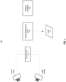
- FIG. 1 depicts a depth map generator system, according to embodiments of the invention.
- the example embodiment shown in FIG. 1 includes two cameras, camera A 105A and camera B 105B , which may be installed onto a rigid physical structure, such as a camera rig, and are pointed in approximately the same direction.
- the cameras may be referred to herein as the right (camera A 105A) and the left (camera B 105B), but it should be noted that they may be oriented differently (such as up and down).
- the distance between the left 105B and right 105A cameras is typically between 5-50 centimeters, although other distances may be used.
- the two cameras capture images (which shall be understood to mean still images, video images, or both) of the same scene but from different positions. The disparity of the same elements in the two images provide cues for estimating depth.
- a microcontroller 110 which is communicatively coupled to each camera.
- the microcontroller sends one or more control signals to the cameras, receives image data from the cameras, and transmits the image data to a processing unit (e.g., CPU 115 ), which is also communicatively coupled to the microcontroller 110.
- the microcontroller may send exposure and gain parameters to the cameras, and may send one or more exposure signals to the two cameras to insure simultaneous exposure so that the two cameras capture their respective images at the same point in time. Simultaneous exposure is important to depth estimation if the scene contains dynamic objects.
- An example microcontroller is the Z-USB FX3 TM SuperSpeed USB 3.0 peripheral controller by Cypress Semiconductor Corporation of San Jose, California, USA, but other microcontrollers may be used.
- a CPU 115 which may be an Advanced RISC Machine (ARM) CPU or a x86 CPU.
- ARM Cortex-A53 designed by Arm Holdings of Cambridge, England, is an example CPU that may be used, and any x86 processors will work, such as the Intel ® Core i3 TM 2310M, designed by Intel of Santa Clara, California.
- the CPU 115 receives image data from the microcontroller 110 , performs the overall depth map generation, and utilizes a hardware accelerator 120 that is communicatively coupled to the CPU for completing parts of the depth map generation process.
- the hardware accelerator 120 may be an FPGA, ASIC, or DSP, which is configured to compute the results of parts of the neural network.
- the microcontroller 110 may be removed from the system 100 if the CPU 115 functions as a microcontroller for camera control.
- the system 100 outputs 125 a depth image, such as a 16-bit image with resolution of 640 ⁇ 480, in which each pixel value represents a depth value.
- the output 125 may also include the raw camera images (e.g., two 640x480 gray or color images) from the left and right cameras 105.
- the output rate depends, at least in part, upon the CPU processing rate (e.g., 10 Hz). It should be noted that other bit sizes, resolutions, and output rates may be used.
- system 100 may comprise other computing system elements, such as power supply, power management, memory, interfaces, and the like, which are not shown in FIG. 1 to avoid obscuring aspects of the present invention. Some examples of such elements, and of computing systems generally, are provided with reference to FIG. 2 .
- aspects of the present patent document may be directed to, may include, or may be implemented on one or more information handling systems/computing systems.
- a computing system may include any instrumentality or aggregate of instrumentalities operable to compute, calculate, determine, classify, process, transmit, receive, retrieve, originate, route, switch, store, display, communicate, manifest, detect, record, reproduce, handle, or utilize any form of information, intelligence, or data.
- a computing system may be or may include a personal computer (e.g., laptop), tablet computer, phablet, personal digital assistant (PDA), smart phone, smart watch, smart package, server (e.g., blade server or rack server), a network storage device, camera, or any other suitable device and may vary in size, shape, performance, functionality, and price.
- the computing system may include random access memory (RAM), one or more processing resources such as a central processing unit (CPU) or hardware or software control logic, ROM, and/or other types of memory.
- Additional components of the computing system may include one or more disk drives, one or more ports for communicating with external devices as well as various input and output (I/O) devices, such as a keyboard, a mouse, touchscreen and/or a video display.
- the computing system may also include one or more buses operable to transmit communications between the various hardware components.
- FIG. 2 depicts a simplified block diagram of a computing device/information handling system (or computing system) according to embodiments of the invention. It will be understood that the functionalities shown for system 200 may operate to support various embodiments of a computing system-although it shall be understood that a computing system may be differently configured and include different components, including having fewer or more components as depicted in FIG. 2 .
- the computing system 200 includes one or more central processing units (CPU) 201 that provides computing resources and controls the computer.
- CPU 201 may be implemented with a microprocessor or the like, and may also include one or more graphics processing units (GPU) 219 and/or a floating-point coprocessor for mathematical computations.
- System 200 may also include a system memory 202, which may be in the form of random-access memory (RAM), read-only memory (ROM), or both.
- RAM random-access memory
- ROM read-only memory
- An input controller 203 represents an interface to various input device(s) 204, such as a keyboard, mouse, touchscreen, and/or stylus.
- the computing system 200 may also include a storage controller 207 for interfacing with one or more storage devices 208 each of which includes a storage medium such as magnetic tape or disk, or an optical medium that might be used to record programs of instructions for operating systems, utilities, and applications, which may include embodiments of programs that implement various aspects of the present invention.
- Storage device(s) 208 may also be used to store processed data or data to be processed in accordance with the invention.
- the system 200 may also include a display controller 209 for providing an interface to a display device 211, which may be a cathode ray tube (CRT), a thin film transistor (TFT) display, organic light-emitting diode, electroluminescent panel, plasma panel, or other type of display.
- the computing system 200 may also include one or more peripheral controllers or interfaces 205 for one or more peripherals 206. Examples of peripherals may include one or more printers, scanners, input devices, output devices, sensors, and the like.
- a communications controller 214 may interface with one or more communication devices 215, which enables the system 200 to connect to remote devices through any of a variety of networks including the Internet, a cloud resource (e.g., an Ethernet cloud, a Fiber Channel over Ethernet (FCoE)/Data Center Bridging (DCB) cloud, etc.), a local area network (LAN), a wide area network (WAN), a storage area network (SAN) or through any suitable electromagnetic carrier signals including infrared signals.
- a cloud resource e.g., an Ethernet cloud, a Fiber Channel over Ethernet (FCoE)/Data Center Bridging (DCB) cloud, etc.
- FCoE Fiber Channel over Ethernet
- DCB Data Center Bridging
- LAN local area network
- WAN wide area network
- SAN storage area network
- electromagnetic carrier signals including infrared signals.
- bus 216 which may represent more than one physical bus.
- various system components may or may not be in physical proximity to one another.
- input data and/or output data may be remotely transmitted from one physical location to another.
- programs that implement various aspects of the invention may be accessed from a remote location (e.g., a server) over a network.
- Such data and/or programs may be conveyed through any of a variety of machine-readable medium including, but are not limited to: magnetic media such as hard disks, floppy disks, and magnetic tape; optical media such as CD-ROMs and holographic devices; magneto-optical media; and hardware devices that are specially configured to store or to store and execute program code, such as application specific integrated circuits (ASICs), programmable logic devices (PLDs), flash memory devices, and ROM and RAM devices.
- ASICs application specific integrated circuits
- PLDs programmable logic devices
- flash memory devices ROM and RAM devices.
- aspects of the present invention may be encoded upon one or more non-transitory computer-readable media with instructions for one or more processors or processing units to cause steps to be performed.
- the one or more non-transitory computer-readable media shall include volatile and non-volatile memory.
- alternative implementations are possible, including a hardware implementation or a software/hardware implementation.
- Hardware-implemented functions may be realized using ASIC(s), FPGA(s), programmable arrays, digital signal processing circuitry, or the like. Accordingly, the "means” terms in any claims are intended to cover both software and hardware implementations.
- computer-readable medium or media includes software and/or hardware having a program of instructions embodied thereon, or a combination thereof.
- embodiments of the present invention may further relate to computer products with a non-transitory, tangible computer-readable medium that have computer code thereon for performing various computer-implemented operations.
- the media and computer code may be those specially designed and constructed for the purposes of the present invention, or they may be of the kind known or available to those having skill in the relevant arts.
- Examples of tangible computer-readable media include, but are not limited to: magnetic media such as hard disks, floppy disks, and magnetic tape; optical media such as CD-ROMs and holographic devices; magneto-optical media; and hardware devices that are specially configured to store or to store and execute program code, such as ASICs, FPGAs, programmable logic devices (PLDs), flash memory devices, and ROM and RAM devices.
- Examples of computer code include machine code, such as produced by a compiler, and files containing higher level code that are executed by a computer using an interpreter.
- Embodiments of the present invention may be implemented in whole or in part as machine-executable instructions that may be in program modules that are executed by a processing device.
- Examples of program modules include libraries, programs, routines, objects, components, and data structures. In distributed computing environments, program modules may be physically located in settings that are local, remote, or both.
- FIGS. 3A-M graphically depict an example deep neural network model that has been trained and may be used to infer depth information from stereo images, according to embodiments of the invention.
- each box 310- x represents a convolution or deconvolution layer, comprises the most computation among all of the types of layers in the network 300.
- each rectangle 315- x represents a rectified linear unit (ReLU) layer, which follows a convolution or deconvolution layer.
- each rectangle 320- x represent one of several types of layers, including data input, slicing, element wise operation, concatenation, and output.
- each octagon 325- x represents a block of data, or the middle results, passed between layers.
- the network 300 received a pair of images (e.g., a left image and a right image) as input, which is represented by the DualImage layer 305 , and scales down their pixel values through an elementwise operation layer, which is depicted as slice_pair 320-1.
- each image passes through the same two convolution layers, namely conv1s 310-1 and conv2s 310-2 .
- these two early stage convolution layers share parameters. Such a configuration has at least a couple significant benefits.
- the resulting feature maps get concatenated by a concatenation layer cct2 320-5, which means that starting from this layer the feature maps from the two images are combined to process together.
- the next eight convolutional layers-including conv3 310-3 , conv3_1 310-4 , conv4 310-5 , conv4_1 310-6, conv5 310-7 , conv5_1 310-8, conv6 310-9 , and conv6_1m 310-10- may be lined up in a typical manner as depicted in FIGS. 3C-E .
- these layers represent a compression stage, in which the spatial resolution (i.e., the width and height) of the feature maps in the network decreases while the number of channels increases.
- the convolution layer convolution11 310-31 predicts a disparity map.
- the depth of a point in a scene is inversely proportional to the difference in distance of corresponding image points in the images and the camera centers. From the disparity map, depth information for pixels in an image may be derived.
- the last layer, DepthOutput 330 converts the disparity map to a depth map and resizes it to the desired resolution.
- the depicted model includes extra branches in addition to the main branch.
- Convolution1m ( FIG. 3E , 310-12) branches at conv6_1 ( FIG. 3E , 325-19), followed by upsample_disp6t05 ( FIG. 3F , 310-13), which eventually reconnects to the main branch at Concat2 ( FIG. 3F , 320-6).
- Convolution3 ( FIG. 3G , 320-16) branches at concat5 ( FIG. 3G , 325-24), which branch includes the deconvolution upsample_disp5t04 ( FIG. 3G , 310-17) and reconnects at Concat3 ( FIG.
- Convolution5 ( FIG. 3H , 310-19) branches after concat4 ( FIG. 3H , 325-29) , which branch includes the deconvolution upsample_disp4t03 ( FIG. 3I , 310-21) and joins at Concat4 ( FIG. 3H , 320-29).
- the model also includes a convolution, Convolution7 ( FIG. 3J , 310-23), that branches at concat3 ( FIG. 3J , 325-34) ; the branch includes the deconvolution upsample_disp3t02 ( FIG. 3J , 310-25) and reconnects to the main branch at Concat5 ( FIG.
- the model also branches after concat2 ( FIG. 3K , 325-39) . That branch includes convolution Convolution9 ( FIG. 3K , 310-28) and upsample_disp2t01 ( FIG. 3L , 310-29) and reconnects at Concat6 ( FIG. 3L , 320-10).
- the octagon items indicate data blocks, which may also be referred to as BLOBs (Binary Large OBjects), and that the "concatX" octagons ( 325- x ) are not concatenation layers.
- the depicted model also includes skip branches in addition to the main branch and extra branches.
- the outputs of the convolution convis ( FIG. 3A , 310-1) for the left and right images is concatenated by the layer cc1 ( FIG. 3B , 320-4 ), which in turn connects to Concat6 ( FIG. 3L , 320-10).
- the output of the concatenation layer cc2 ( FIG. 3B , 320-5 ) connects to Concat5 ( FIG. 3K , 320-9).
- conv3_1 FIG.
- a skip branch forms that connect to Concat4 ( FIG. 3I , 320-8) .
- another skip branch forms and connects to Concat3 ( FIG. 3H , 320-7 ).
- a skip branch forms that connects to Concat2 ( FIG. 3F , 320-6 ).
- FIGS. 4A-K depict an example network model that may be used at training time, according to embodiments of the invention.
- the training model comprises a number of similarity with the deployed model illustrated in FIGS. 3A-L and described in the prior section. Accordingly, to avoid unnecessary repetition, this section describes differences in the training network embodiment depicted in FIGS. 4A-K compared to the network embodiment at inference time as shown in FIGS. 3A-L .
- the network's first layer ImagePairsAndGT ( FIG. 4A , 405 ) takes a pair of training images and a corresponding ground truth (GT) disparity map as input.
- data augmentation is performed on the image pair through the layers imgos_aug ( FIG. 4A , 420-3 ), GenAugParams ( FIG. 4B , 420-4 ), and imgis_aug ( FIG. 4B , 420-6 ), while a corresponding augmentation is performed on the disparity ground truth through layer DispAugmentation1 ( FIG. 4B , 420-5 ).
- these data augmentation layers randomly generate and apply image transforms, including translation, rotation, and color change, to the image pairs.
- the augmented images are input to a convolution, conv1s ( FIG. 4B , 410-1) separately, just as at inference.
- the augmented ground truth disparity map from layer DispAugmentation1 goes through multiple downsampling layers separately, including Downsample1 ( FIG. 4H , 420-11) , Downsample2 ( FIG. 4H , 420-10 ), Downsample3 ( FIG. 4J , 420-15 ), Downsample4 ( FIG. 4K , 420-18 ), Downsample5 ( FIG. 4M , 420-21) , and Downsample6 ( FIG. 4N , 420-24 ).
- each connects, directly or indirectly, to a loss layer, such as disp_loss6 ( FIG.
- auxiliary predictions to compute the loss of auxiliary predictions from the branches or the final disparity prediction, which branches were described with reference to the inference network structure in FIGS. 3A-K .
- These layers are referred to as auxiliary predictions because they predict the disparity in the middle of the network to help backpropagate the loss to early layers during training, which helps speed convergence.
- the network at training time comprises more layers, including data augmentation layers and sampling layers, that may be deliberately removed from a deployed network embodiment. It was found that removal of these layers had little effect on the final performance of the network in inferring depth but had a substantial reduction in processing requirements. These reductions in processing are, at least in part, one of the reasons that the deployed network may be implemented using a hardware accelerator unit, like an FPGA. Also, by reducing the computation requirements, the depth inference can be done in real-time (or near real-time).
- FIGS. 3A-M a deployed, or trained, network model embodiment
- FIGS. 4A-N a network model embodiment during training
- Table 1 depicts information related to some of the layers of the illustrated deep neural network embodiments.
- Table 1 Example Parameters for Certain Layers in the Network Embodiments Name Kernel Size Stride Input Channel Number Output Channel Number Input layer conv1s 7 2 3 32 image conv2s 5 2 32 64 conv1s conv3 5 2 128 256 conv2s conv3_1 3 1 256 256 conv3 conv4 3 2 256 512 conv3_1 conv4_1 3 1 512 512 conv4 conv5 3 2 512 512 512 conv4_1 conv5_1 3 1 512 512 conv5 conv6 3 2 512 1024 conv5_1 conv6_1m 3 1 1024 512 conv6 Convolution1m 3 1 512 1 conv6_1m upsample_disp6to5 4 2 1 1 Convolution1m deconv5m 4 2 512 256 conv6_1m Convolution2m 3 1 769 512 conv5_1, upsample_disp6to5, deconv5m Convolution3 3 1
- FIG. 5 depicts a general overall method for training and using a neural network model for depth map estimation, according to embodiments of the present invention.
- a camera system such as cameras 105A and 105B in FIG. 1
- Initializing the camera helps to set proper exposure and gain parameters for the cameras, and may also involve calibration of the cameras.
- At least two methods may be used.
- a first method comprises using pre-known parameters.
- a second method may be used that comprises collecting a few sample images with a set of fixed parameters and calculating camera parameters based on the sample images.
- Camera initialization/calibration is well known in the art and no particular method is critical to the invention.
- the neural network model may be trained ( 510 ). It should be noted that the model may be trained using real data (i.e., captured images with corresponding ground truth depth information/disparity maps), using synthetic data (i.e., computer-generated images with corresponding ground truth depth information/disparity maps), or both.
- real data i.e., captured images with corresponding ground truth depth information/disparity maps
- synthetic data i.e., computer-generated images with corresponding ground truth depth information/disparity maps
- FIG. 6 depicts an example method for training a deep neural network model for depth estimation according to embodiments of the invention. It shall be noted that the embodiment depicted in FIG. 6 contemplates training the neural network using computationally capable workstations but deploying the trained neural network using hardware accelerator component that may not be as computationally capable as the workstation but is efficient and inexpensive.
- an initial training set of data may be used ( 605 ) to train the neural network in a floating-point mode using one or more workstations, preferably with a graphical processor unit or units (GPUs) to aid in the heavy computation requirements of training.
- the initial training set of data may be synthetic training data (i.e., computer-generated images with corresponding disparity maps).
- additional training may be performed ( 610 ) using a second set of training data.
- the second set of training data may be real images along with their corresponding disparity map as ground truth to fine-tune the network on real data to improve the performance on real environment.
- different bit representations are used to fine-tune the model to better align it for its deployment when deployed using a hardware accelerator component that uses a different bit representation for computation than used by the training workstation.
- 8-bit trained fine-tuning may be performed ( 615 ) on the above-mentioned floating-point network in 8-bit mode to produce an 8-bit network, in which network parameters are quantized to 8-bit representation.
- FIG. 7 depicts a method for fine-tuning, as part of training, a floating-point neural network model by simulating a certain bit representation to produce a neural network for use on a hardware accelerator component that uses that certain bit representation, according to embodiments of the invention.
- the workstation uses a 32-bit floating-point representation for values
- the hardware accelerator is an FPGA that uses 8-bit fixed-point representation for operation computations, although other representations and implementations may be used.
- FIG. 1 depicts a method for fine-tuning, as part of training, a floating-point neural network model by simulating a certain bit representation to produce a neural network for use on a hardware accelerator component that uses that certain bit representation, according to embodiments of the invention.
- the workstation uses a 32-bit floating-point representation for values
- the hardware accelerator is an FPGA that uses 8-bit fixed-point representation for operation computations, although other representations and implementations may be used.
- FIG. 1 shows a method for fine-tuning, as part
- the image-related input data e.g., data that is input image data or derived from the input image data by, for example, having undergone one or more prior operations
- the operation parameter data e.g., the weights for a layer
- these 8-bit fixed representations of the values for the input data and the operation parameter data are dequantized ( 715 ) to 32-bit floating-point values.
- the neural network operation or operations e.g., the layer operation, such as convolution, deconvolution, etc.
- the layer operation such as convolution, deconvolution, etc.
- the results data of the operation or operations may be output ( 725 ) as 32-bit floating-point values.
- the conversions and dequantizations may involve conversion to one or more intermediate bit representations.
- the image-relate input data 802 may be converted (805) from 32-bit floating-point representation of values to 18-bit floating-point representation of values.
- this process may be handled automatically by the hardware accelerator when the CPU initiates the request/command of writing the data to the memory (e.g., double data rate random access memory (DDR RAM)) of the hardware accelerator component.
- DDR RAM double data rate random access memory
- the layer parameter data is fixed or relatively fixed and can be stored in 8-bit integers in memory.
- the input data for each layer changes and has different ranges; thus, the input data is not directly represented in 8-bit in memory.
- float values are used for this data and to save space and time, shorter float values may be used in memory.
- 18-bit floating point is used but other sizes, like 16-bit floating point could also be used.
- the 18-bit floating-point values may be converted (810) to 8-bit integers on the fly using a conversion, such as the ABSMAX methodology (described below) each time.
- the remainder of the depicted embodiment in FIG. 8 proceeds in like manner as that described in FIG. 7 . It should be noted that alternative methods may comprise fewer or more bit representation conversions.
- FIG. 9 graphically depicts a method for quantizing values represented in one bit representation scheme into a different bit representation scheme, according to embodiments of the invention.
- the top line 905 represents a first bit representation scheme, which is 32-bit floating-point representation in this example but may be a different representation
- the bottom line 910 represents a second bit representation scheme, which is 8-bit floating-point representation in this example but may be a different representation.
- Conv Blob FP 32 Image Blob FP 32 Filter ABSMAX Image * ABSMAX Filter / 127 * 127 * Conv Blob Fix 8 Image Blob Fix 8 Filter
- ABSMAX Image is the absolute maximum value in the image-related data
- ABSMAX Filter is the absolute maximum value in the operation filter's parameters.
- At least two early stage convolution operations in the neural network model may be configured to each operate separately on image-related data corresponding the first image and the second image instead of operating on a set of data representing a combination of the image-related data.
- the two convolutions, convolis ( 310-1 in FIG. 3A / 410-1 in FIG. 4C ) and convol2s ( 310-2 in FIG. 3B / 410-2 in FIG. 4C ) each operate on data corresponding to the two input images separately and then concatenate the results instead of each operating on a stack of data related to the two input images.
- certain operations may reduce the number of channels to help reduce computation.
- the network may be deployed ( 520 ) to obtain depth information, such as a disparity map or depth map, given stereo images as input.
- FIG. 10 depicts a method for using a trained neural network model with a hardware acceleration unit to provide dense depth map information in real-time (or near real-time), according to embodiments of the invention.
- a depth map estimation system like one depicted in FIG. 1 , is used to capture ( 1005 ) a set of stereo images of a scene.
- the images represent two views of a scene.
- the images may be captured by having the CPU sends a signal to the microcontroller that it is expecting a new pair of stereo image.
- the microcontroller may then cause the two cameras to contemporaneously capture images. After the exposure is done, the image data may be transmitted from the cameras to the CPU via microcontroller.
- the CPU receives 640 ⁇ 480 ⁇ 2 ⁇ 8 bytes of data-if the cameras are gray, or 640 ⁇ 480 ⁇ 2 ⁇ 3 ⁇ 8 bytes of data-if the cameras are color.
- the system may not include a microcontroller and its functions may be performed by a CPU. It should be noted that the depict method embodiment does not include an initialization/calibration phase; however, if initialization/calibration is desired, it may be performed in like manner as previously described, above.
- the input images data may then be processed ( 1010 ) according to a deployed neural network model, such as one like that depicted in FIG. 3A-M .
- the CPU and hardware accelerator component cooperate to run the deployed deep neural network.
- the CPU may control the general workflow, and sequentially assign one or more layers' computation task to the hardware accelerator component.
- the hardware accelerator component fetches data and layer parameters from the CPU and/or from memory, performs that layer's computation (e.g., convolution, deconvolution, concatenation, etc.), and returns (1015) the processed data to the CPU and/or memory.
- the final result which may be a depth map image or a depth image data and the raw input image data
- This final output data may be stored for later use, transferred via a communication protocol (e.g., Universal Serial Bus (USB), Ethernet, Serial, Parallel, etc.) and/or used by a corresponding system or the same system for ensuing tasks.
- a communication protocol e.g., Universal Serial Bus (USB), Ethernet, Serial, Parallel, etc.
- USB Universal Serial Bus
- Ethernet Serial, Parallel, etc.
- the depth map information may be used for obstacle detection for an autonomous vehicle.
- the system may return ( 1025 ) to the step of capturing the next pair of stereo images to start a next cycle. This process may be repeated until a stop condition has been reached.
- a stop condition depends upon the application of the depth map information. In the case of an autonomous vehicle, it may continue so long as the vehicle is in operation. Other stop conditions may include obtaining a set number of depth maps, operating for a certain amount of time, operating until an instruction to stop is received, and the like.
- the hardware accelerator is an FPGA, but as previously noted, other components may also be used. Also, it should be noted that the depicted embodiment shows the steps in relation to the components involved, namely the CPU 1160, the FPGA memory 1165, and the FPGA chip 1170 ; however, the steps may be allocated differently, provided this falls within the scope of the invention as defined by the claims.
- the operation parameter data (e.g., the weights for a layer) 1104 is directly converted (1115) from 32-bit floating-point values to 8-bit fixed-point values and stored in the FPGA's memory 1165 .
- the layer weights since at deployment time the layer weights do not change and have fixed range, they can be directly represented in 8-bit in the memory.
- the FPGA when the FPGA performs the layer operation computation, it accesses the input data in its memory and quantizes (1110) it and also accesses the parameters, which are already in an 8-bit fixed representation.
- the two sets of data may undergo an operation, such as a fixed multiply accumulate operation ( 1120 ) to produce results data, which may be in a 64-bit fixed representation. In one or more embodiments, this results data may be dequantized (1125) to a floating-point 32-bit representation.
- this results data may be interim or intermediate results data that may undergo one or more additional operations.
- the data may undergo one or more additional operations (e.g., 1130 and 1135 ) like scaling, bias, batch normalization, ReLU operations, max pooling, etc.
- the results data is converted (1140) to an 18-bit floating point representation and stored in memory.
- the 18-bit conversions (1105 and 1140) from the CPU into the FPGA memory and from the FPGA core into the FPGA memory may be skipped if the FPGA memory supports 32-bit floating point memory.
- the method may involve fewer or more bit representation conversions.
- the CPU may access the stored values, in which the 18-bit floating point representation of the values may be converted ( 1145 ) to 32-bit floating-point values.
- the output results 1150 may be the final results of the neural network, such as a depth map, or may be intermediate results of neural network, in which these results may be used for a subsequent layer.
- the results after stage 1140 may be the next layer's "image" going into box 1110.
Landscapes
- Engineering & Computer Science (AREA)
- Theoretical Computer Science (AREA)
- Physics & Mathematics (AREA)
- Software Systems (AREA)
- General Physics & Mathematics (AREA)
- General Engineering & Computer Science (AREA)
- Evolutionary Computation (AREA)
- Mathematical Physics (AREA)
- Data Mining & Analysis (AREA)
- Artificial Intelligence (AREA)
- Computing Systems (AREA)
- Computational Linguistics (AREA)
- Health & Medical Sciences (AREA)
- Life Sciences & Earth Sciences (AREA)
- Biophysics (AREA)
- Biomedical Technology (AREA)
- General Health & Medical Sciences (AREA)
- Molecular Biology (AREA)
- Computer Vision & Pattern Recognition (AREA)
- Medical Informatics (AREA)
- Neurology (AREA)
- Image Analysis (AREA)
- Image Processing (AREA)
Claims (15)
- Bildverarbeitungssystem, das Folgendes umfasst:eine Prozessoreinheit (115);eine Hardwarebeschleunigerkomponente (120); undein nichttransitorisches computerlesbares Medium oder nichttransitorische computerlesbare Medien, das/die eine oder mehrere Sequenzen von Anweisungen umfasst/umfassen, die bei Ausführung durch die Prozessoreinheit bewirken, dass Schritte durchgeführt werden, die Folgendes umfassen:Empfangen eines Paars von Bildern (305) einer Szene, wobei das Paar von Bildern (305) ein erstes Bild und ein zweites Bild umfasst;Durchführen von Tiefenkarteninferenz unter Verwendung des Paars von Bildern (305) und eines trainierten neuronalen Netzwerkmodells (300), das eine Vielzahl von Operationen umfasst, wobei mindestens einige der Operationen der Vielzahl von Operationen des trainierten neuronalen Netzwerkmodells durch die Hardwarebeschleunigerkomponente (120) durchgeführt werden, die kommunikativ mit der Prozessoreinheit (115) gekoppelt ist, wobei das Paar von Bildern (305) als eine Eingabe des trainierten neuronalen Netzwerkmodells (300) verwendet wird; undAusgeben, durch das trainierte neuronale Netzwerkmodell (300), einer Tiefenkarte (125), die Abstandsinformationen zu Oberflächen in der Szene umfasst; undwobei die Hardwarebeschleunigerkomponente (120) dazu konfiguriert ist, mindestens einige der Operationen des trainierten neuronalen Netzwerkmodells unter Verwendung einer anderen Bitrepräsentation als der, die durch die Prozessoreinheit (115) verwendet wird, durchzuführen;wobei die Prozessoreinheit (115) und die Hardwarebeschleunigerkomponente (120) für das Paar von Bildern (305) zusammenwirken, um das trainierte neuronale Netzwerkmodell auszuführen, einschließlich des Folgenden: die Prozessoreinheit (115) steuert einen Arbeitsablauf des trainierten neuronalen Netzwerks und weist der Hardwarebeschleunigerkomponente (120) sequentiell eine Rechenaufgabe einer oder mehrerer Schichten zu, wobei die Hardwarebeschleunigerkomponente (120) Daten und Schichtparameter von der Prozessoreinheit (115) abruft, die Rechenaufgabe der Schicht durchführt und verarbeitete Daten an die Prozessoreinheit (115) zurückgibt;wobei das neuronale Netzwerk unter Verwendung einer oder mehrerer Trainingsarbeitsstationen trainiert wird, wobei die eine oder die mehreren Trainingsarbeitsstationen eine andere Bitrepräsentation als die Hardwarebeschleunigerkomponente (120) verwenden; undwobei das trainierte Modell für den Einsatz unter Verwendung der Hardwarebeschleunigerkomponente (120) feinabgestimmt ist, wobei das Feinabstimmen eine Bitrepräsentationsumwandlung verwendet, um eine Operation zu simulieren, die durch die Hardwarebeschleunigerkomponente (120) durchgeführt wird, wenn das trainierte neuronale Netzwerk eingesetzt wird.
- Bildverarbeitungssystem nach Anspruch 1, wobei die Prozessoreinheit (115) unter Verwendung einer Gleitkommabitrepräsentation arbeitet und die Hardwarebeschleunigerkomponente (120) weniger Bits verwendet und eine Festbitrepräsentation verwendet.
- Bildverarbeitungssystem nach Anspruch 1, wobei der Schritt des Verwendens einer Bitrepräsentationsumwandlung, um eine Operation zu simulieren, die durch die Hardwarebeschleunigerkomponente (120) durchgeführt wird, wenn das trainierte neuronale Netzwerk eingesetzt wird, Folgendes umfasst:Umwandeln (705) von Eingangsdaten für die Operation von einer Gleitkommabitrepräsentation, die durch die eine oder die mehreren Trainingsarbeitsstationen verwendet wird, in eine Festbitrepräsentation, die durch die Hardwarebeschleunigerkomponente (120) verwendet wird;Umwandeln (710) von Operationsparameterdaten für die Operation von einer Gleitkommabitrepräsentation, die durch die eine oder die mehreren Trainingsarbeitsstationen verwendet wird, in eine Festbitrepräsentation, die durch die Hardwarebeschleunigerkomponente (120) verwendet wird;Dequantisieren (715) der Festbitrepräsentation der Eingangsdaten und der Operationsparameterdaten in eine Gleitkommarepräsentation;Durchführen (720) der Operation unter Verwendung der dequantisierten Gleitkommarepräsentation der Eingangsdaten und der Operationsparameterdaten; undAusgeben (725) eines Satzes von Ergebnisdaten aus der Operation in der dequantisierten Gleitkommarepräsentation.
- Bildverarbeitungssystem nach Anspruch 3, wobei die dequantisierte Gleitkommawertrepräsentation die Gleitkommabitrepräsentation ist, die durch die eine oder die mehreren Trainingsarbeitsstationen verwendet wird.
- Bildverarbeitungssystem nach Anspruch 1, wobei das neuronale Netzwerkmodell, das beim Training verwendet wird, eine oder mehrere Datenerweiterungsschichten (420-3, 420-4, 420-6, 420-5) und eine oder mehrere Abtastschichten (420-11, 420-10, 420-15, 420-18, 420-21, 420-24) umfasst, die entfernt werden, wenn das trainierte neuronale Netzwerkmodell erzeugt wird, um die Verarbeitungszeit während des Einsatzes zu verbessern.
- Bildverarbeitungssystem nach Anspruch 1, wobei das trainierte neuronale Netzwerkmodell die Berechnung reduziert, indem es zwei Frühphasenfaltungsoperationen (310-1, 310-2, 410-1, 410-2) in dem trainierten neuronalen Netzwerkmodell umfasst, die jeweils separat an bildbezogenen Daten arbeiten, die dem ersten Bild und dem zweiten Bild entsprechen, anstatt an einem Satz von Daten zu arbeiten, die eine Kombination der bildbezogenen Daten repräsentieren, die dem ersten Bild und dem zweiten Bild entsprechen, und wobei die zwei Frühphasenfaltungsoperationen Parameter gemeinsam nutzen.
- Bildverarbeitungssystem nach Anspruch 1, wobei das Bildverarbeitungssystem mindestens einige der Operationen des trainierten neuronalen Netzwerkmodells unter Verwendung einer anderen Bitrepräsentation als der, die durch die Prozessoreinheit (115) verwendet wird, durch Durchführen der folgenden Schritte durchführt:Umwandeln von Eingangsdaten für die Operation von einer Gleitkommabitrepräsentation, die durch die Prozessoreinheit (115) verwendet wird, in eine Festbitrepräsentation, die durch die Hardwarebeschleunigerkomponente (120) verwendet wird;Umwandeln von Operationsparameterdaten für die Operation von einer Gleitkommabitrepräsentation, die durch die Prozessoreinheit (115) verwendet wird, in eine Festbitrepräsentation, die durch die Hardwarebeschleunigerkomponente (120) verwendet wird;Durchführen der Operation an der Hardwarebeschleunigerkomponente (120) unter Verwendung der Festbitrepräsentation der Eingangsdaten und der Operationsparameterdaten, um Ergebnisdaten zu erhalten; undDequantisieren der Festbitrepräsentation der Ergebnisdaten in eine Gleitkommarepräsentation,wobei die Ergebnisdaten vorzugsweise Zwischenergebnisdaten sind und das Bildverarbeitungssystem vorzugsweise ferner die folgenden Schritte durchführt:
Durchführen, unter Verwendung der Hardwarebeschleunigerkomponente (120), einer oder mehrerer Operationen an der dequantisierten Festbitrepräsentation der Zwischenergebnisdaten, bevor Ergebnisdaten an die Prozessoreinheit übermittelt werden. - Bildverarbeitungssystem, das Folgendes umfasst:eine Prozessoreinheit (115);eine Hardwarebeschleunigerkomponente (120); undein nichttransitorisches computerlesbares Medium oder nichttransitorische computerlesbare Medien, das/die eine oder mehrere Sequenzen von Anweisungen umfasst/umfassen, die bei Ausführung durch die Prozessoreinheit bewirken, dass Schritte durchgeführt werden, die Folgendes umfassen:Empfangen, durch ein trainiertes neuronales Netzwerkmodell (300), wobei ein neuronales Netzwerkmodell, von dem das trainierte neuronale Netzwerkmodell (300) abgeleitet ist, einen Satz von Datenerweiterungsoperationen (420-3, 420-4, 420-6, 420-5) und einen Satz von einer oder mehreren Abtastoperationen (420-11, 420-10, 420-15, 420-18, 420-21, 420-24) umfasst, eines Paars von Bildern (305) einer Szene, wobei das Paar von Bildern (305) ein erstes Bild und ein zweites Bild umfasst;Durchführen von Tiefenkarteninferenz unter Verwendung des Paars von Bildern (305) und des trainierten neuronalen Netzwerkmodells (300), das eine Vielzahl von Operationen umfasst, die eine Vielzahl von Faltungen und Entfaltungen umfasst, und das dazu konfiguriert wurde, Berechnungsanforderungen zu reduzieren, indem:es mindestens zwei Faltungsoperationen (310-1, 310-2, 410-1, 410-2) umfasst, die jeweils separat an bildbezogenen Daten arbeiten, die dem ersten Bild und dem zweiten Bild entsprechen, anstatt an einer Kombination der bildbezogenen Daten zu arbeiten, die dem ersten Bild und dem zweiten Bild entsprechen, und wobei die zwei Frühphasenfaltungsoperationen (310-1, 310-2, 410-1, 410-2) Parameter gemeinsam nutzen; undes nicht den Satz von Datenerweiterungsoperationen (420-3, 420-4, 420-6, 420-5) und den Satz von einer oder mehreren Abtastoperationen (420-11, 420-10, 420-15, 420-18,420-21,420-24) umfasst, die in einem neuronalen Netzwerkmodell enthalten waren, von dem das trainierte neuronale Netzwerkmodell (300) abgeleitet ist; und Ausgeben, durch das trainierte neuronale Netzwerkmodell (300), einer Tiefenkarte (125), die Abstandsinformationen zu Oberflächen in der Szene umfasst; undwobei die Hardwarebeschleunigerkomponente kommunikativ mit der Prozessoreinheit gekoppelt ist, die dazu konfiguriert ist, mindestens einige der Operationen des trainierten neuronalen Netzwerkmodells durchzuführen,wobei die Prozessoreinheit (115) und die Hardwarebeschleunigerkomponente (120) für das Paar von Bildern (305) zusammenwirken, um das trainierte neuronale Netzwerkmodell auszuführen, einschließlich des Folgenden: die Prozessoreinheit (115) steuert einen Arbeitsablauf des trainierten neuronalen Netzwerks und weist der Hardwarebeschleunigerkomponente (120) sequentiell eine Rechenaufgabe einer oder mehrerer Schichten zu, wobei die Hardwarebeschleunigerkomponente (120) Daten und Schichtparameter von der Prozessoreinheit (115) abruft, die Rechenaufgabe der Schicht durchführt und verarbeitete Daten an die Prozessoreinheit (115) zurückgibt;wobei das neuronale Netzwerk unter Verwendung einer oder mehrerer Trainingsarbeitsstationen trainiert wird, wobei die eine oder die mehreren Trainingsarbeitsstationen eine andere Bitrepräsentation als die Hardwarebeschleunigerkomponente (120) verwenden; undwobei das trainierte Modell für den Einsatz unter Verwendung der Hardwarebeschleunigerkomponente (120) feinabgestimmt ist, wobei das Feinabstimmen eine Bitrepräsentationsumwandlung verwendet, um eine Operation zu simulieren, die durch die Hardwarebeschleunigerkomponente (120) durchgeführt wird, wenn das trainierte neuronale Netzwerk eingesetzt wird.
- Bildverarbeitungssystem nach Anspruch 8, wobei die Prozessoreinheit (115) unter Verwendung einer Gleitkommabitrepräsentation arbeitet und die Hardwarebeschleunigerkomponente (120) weniger Bits verwendet und eine Festbitrepräsentation verwendet.
- Bildverarbeitungssystem nach Anspruch 8, wobei der Schritt des Verwendens einer Bitrepräsentationsumwandlung, um eine Operation zu simulieren, die durch die Hardwarebeschleunigereinheit (120) durchgeführt wird, wenn das trainierte neuronale Netzwerk eingesetzt wird, Folgendes umfasst:Umwandeln (705) von Eingangsdaten für die Operation von einer Gleitkommabitrepräsentation, die durch die eine oder die mehreren Trainingsarbeitsstationen verwendet wird, in eine Festbitrepräsentation, die durch die Hardwarebeschleunigerkomponente (120) verwendet wird;Umwandeln (710) von Operationsparameterdaten für die Operation von einer Gleitkommabitrepräsentation, die durch die eine oder die mehreren Trainingsarbeitsstationen verwendet wird, in eine Festbitrepräsentation, die durch die Hardwarebeschleunigerkomponente (120) verwendet wird;Dequantisieren (715) der Festbitrepräsentation der Eingangsdaten und der Operationsparameterdaten in eine Gleitkommarepräsentation;Durchführen (720) der Operation unter Verwendung der dequantisierten Gleitkommarepräsentation der Eingangsdaten und der Operationsparameterdaten; undAusgeben (725) eines Satzes von Ergebnisdaten aus der Operation in der dequantisierten Gleitkommarepräsentation.
- Bildverarbeitungssystem nach Anspruch 8, wobei das Bildverarbeitungssystem mindestens einige der Operationen des trainierten neuronalen Netzwerkmodells unter Verwendung einer anderen Bitrepräsentation als der, die durch die Prozessoreinheit (115) verwendet wird, durch Durchführen der folgenden Schritte durchführt:Umwandeln von Eingangsdaten für die Operation von einer Gleitkommabitrepräsentation, die durch die Prozessoreinheit (115) verwendet wird, in eine Festbitrepräsentation, die durch die Hardwarebeschleunigerkomponente (120) verwendet wird;Umwandeln von Operationsparameterdaten für die Operation von einer Gleitkommabitrepräsentation, die durch die Prozessoreinheit (115) verwendet wird, in eine Festbitrepräsentation, die durch die Hardwarebeschleunigerkomponente (120) verwendet wird;Durchführen der Operation an der Hardwarebeschleunigerkomponente (120) unter Verwendung der Festbitrepräsentation der Eingangsdaten und der Operationsparameterdaten, um Ergebnisdaten zu erhalten; undDequantisieren der Festbitrepräsentation der Ergebnisdaten in eine Gleitkommarepräsentation,wobei die Ergebnisdaten vorzugsweise Zwischenergebnisdaten sind und das Bildverarbeitungssystem ferner die folgenden Schritte durchführt:
Durchführen, unter Verwendung der Hardwarebeschleunigerkomponente (120), einer oder mehrerer Operationen an der dequantisierten Festbitrepräsentation der Zwischenergebnisdaten, bevor Ergebnisdaten an die Prozessoreinheit (115) übermittelt werden. - Verfahren zum Verarbeiten von Bilddaten, um Tiefeninformationen zu erhalten, die sich auf eine Szene beziehen, die von einem Paar von Bildern aufgenommen wird, wobei das Verfahren Folgendes umfasst:Empfangen des Paars von Bildern (305), das ein erstes Bild und ein zweites Bild der Szene umfasst, an einem Bildverarbeitungssystem, das Folgendes umfasst:eine Prozessoreinheit (115), die dazu konfiguriert ist, einen Arbeitsablauf für ein trainiertes neuronales Netzwerkmodell zu koordinieren, indem mindestens einige der Rechenaufgaben einer oder mehrerer Schichten des trainierten neuronalen Netzwerkmodells einer Hardwarebeschleunigerkomponente (120) zugewiesen werden, die kommunikativ mit der Prozessoreinheit (115) gekoppelt ist, wobei das Paar von Bildern (305) als eine Eingabe des trainierten neuronalen Netzwerkmodells (300) verwendet wird;einen nichttransitorischen computerlesbaren Speicher, der kommunikativ mit der Prozessoreinheit (115) gekoppelt ist, zum Speichern von Daten, die sich auf das Paar von Bildern (305) beziehen, und von Daten, die eine oder mehrere Sequenzen von Anweisungen umfassen, die sich auf das trainierte neuronale Netzwerk beziehen; undwobei die Hardwarebeschleunigerkomponente (120) kommunikativ mit der Prozessoreinheit (115) gekoppelt ist und dazu konfiguriert ist, mindestens einige Operationen eines trainierten neuronalen Netzwerkmodells unter Verwendung einer anderen Bitrepräsentation als der, die durch die Prozessoreinheit (115) verwendet wird, durchzuführen;unter Verwendung des Bildverarbeitungssystems, Durchführen von Tiefenkarteninferenz unter Verwendung des Paars von Bildern (305) und des trainierten neuronalen Netzwerkmodells, das eine Vielzahl von Operationen umfasst, wobei mindestens einige der Operationen der Vielzahl von Operationen des trainierten neuronalen Netzwerkmodells durch die Hardwarebeschleunigerkomponente (120) durchgeführt werden, die kommunikativ mit der Prozessoreinheit (115) gekoppelt ist, wobei die Prozessoreinheit (115) und die Hardwarebeschleunigerkomponente (120) für das Paar von Bildern (305) zusammenwirken, um das trainierte neuronale Netzwerkmodell auszuführen, einschließlich des Folgenden: die Hardwarebeschleunigerkomponente (120) ruft Daten und Schichtparameter von der Prozessoreinheit (115) ab, führt die Rechenaufgabe der Schicht durch und gibt verarbeitete Daten an die Prozessoreinheit (115) zurück; undAusgeben, durch das trainierte neuronale Netzwerkmodell (300), einer Tiefenkarte (125), die Tiefeninformationen zu Oberflächen in der Szene umfasst;wobei das neuronale Netzwerk unter Verwendung einer oder mehrerer Trainingsarbeitsstationen trainiert wird, wobei die eine oder die mehreren Trainingsarbeitsstationen eine andere Bitrepräsentation als die Hardwarebeschleunigerkomponente (120) verwenden; undwobei das trainierte Modell für den Einsatz unter Verwendung der Hardwarebeschleunigerkomponente (120) feinabgestimmt ist, wobei das Feinabstimmen eine Bitrepräsentationsumwandlung verwendet, um eine Operation zu simulieren, die durch die Hardwarebeschleunigerkomponente (120) durchgeführt wird, wenn das trainierte neuronale Netzwerk eingesetzt wird.
- Verfahren nach Anspruch 12, wobei ein neuronales Netzwerkmodell, das beim Trainieren des trainierten neuronalen Netzwerkmodells verwendet wird, eine oder mehrere Datenerweiterungsschichten (420-3, 420-4, 420-6, 420-5) und eine oder mehrere Abtastschichten (420-11, 420-10, 420-15, 420-18, 420-21, 420-24) umfasst, die entfernt werden, wenn das trainierte neuronale Netzwerkmodell erzeugt wird, um die Verarbeitungszeit während des Einsatzes zu verbessern.
- Verfahren nach Anspruch 12, wobei das trainierte neuronale Netzwerkmodell die Berechnung reduziert, indem es zwei Frühphasenfaltungsoperationen (310-1, 310-2, 410-1, 410-2) in dem trainierten neuronalen Netzwerkmodell umfasst, die jeweils separat an bildbezogenen Daten arbeiten, die dem ersten Bild und dem zweiten Bild entsprechen, anstatt an einem Satz von Daten zu arbeiten, die eine Kombination der bildbezogenen Daten repräsentieren, die dem ersten Bild und dem zweiten Bild entsprechen, und wobei die zwei Frühphasenfaltungsoperationen Parameter gemeinsam nutzen.
- Verfahren nach Anspruch 12, wobei das Bildverarbeitungssystem mindestens einige der Operationen des trainierten neuronalen Netzwerkmodells unter Verwendung einer anderen Bitrepräsentation als der, die durch die Prozessoreinheit (115) verwendet wird, durch Durchführen der folgenden Schritte durchführt:Umwandeln von Eingangsdaten für die Operation von einer Gleitkommabitrepräsentation, die durch die Prozessoreinheit (115) verwendet wird, in eine Festbitrepräsentation, die durch die Hardwarebeschleunigerkomponente (120) verwendet wird;Umwandeln von Operationsparameterdaten für die Operation von einer Gleitkommabitrepräsentation, die durch die Prozessoreinheit (115) verwendet wird, in eine Festbitrepräsentation, die durch die Hardwarebeschleunigerkomponente (120) verwendet wird;Durchführen der Operation an der Hardwarebeschleunigerkomponente (120) unter Verwendung der Festbitrepräsentation der Eingangsdaten und der Operationsparameterdaten, um Ergebnisdaten zu erhalten.
Applications Claiming Priority (1)
| Application Number | Priority Date | Filing Date | Title |
|---|---|---|---|
| PCT/CN2017/115228 WO2019109336A1 (en) | 2017-12-08 | 2017-12-08 | Stereo camera depth determination using hardware accelerator |
Publications (3)
| Publication Number | Publication Date |
|---|---|
| EP3607744A1 EP3607744A1 (de) | 2020-02-12 |
| EP3607744A4 EP3607744A4 (de) | 2020-04-29 |
| EP3607744B1 true EP3607744B1 (de) | 2024-07-24 |
Family
ID=66750686
Family Applications (1)
| Application Number | Title | Priority Date | Filing Date |
|---|---|---|---|
| EP17933955.1A Active EP3607744B1 (de) | 2017-12-08 | 2017-12-08 | Tiefenbestimmung bei einer stereokamera mit hardwarebeschleuniger |
Country Status (4)
| Country | Link |
|---|---|
| US (1) | US11182917B2 (de) |
| EP (1) | EP3607744B1 (de) |
| CN (1) | CN110574371B (de) |
| WO (1) | WO2019109336A1 (de) |
Families Citing this family (37)
| Publication number | Priority date | Publication date | Assignee | Title |
|---|---|---|---|---|
| CN110248861B (zh) | 2018-01-07 | 2023-05-30 | 辉达公司 | 在车辆操纵过程中使用机器学习模型来引导车辆 |
| US11079764B2 (en) | 2018-02-02 | 2021-08-03 | Nvidia Corporation | Safety procedure analysis for obstacle avoidance in autonomous vehicles |
| US11210537B2 (en) | 2018-02-18 | 2021-12-28 | Nvidia Corporation | Object detection and detection confidence suitable for autonomous driving |
| US10997433B2 (en) | 2018-02-27 | 2021-05-04 | Nvidia Corporation | Real-time detection of lanes and boundaries by autonomous vehicles |
| DE112019000048T5 (de) | 2018-03-15 | 2020-01-16 | Nvidia Corporation | Bestimmung eines befahrbaren freiraums für autonome fahrzeuge |
| WO2019182974A2 (en) | 2018-03-21 | 2019-09-26 | Nvidia Corporation | Stereo depth estimation using deep neural networks |
| WO2019191306A1 (en) | 2018-03-27 | 2019-10-03 | Nvidia Corporation | Training, testing, and verifying autonomous machines using simulated environments |
| WO2019222467A1 (en) * | 2018-05-17 | 2019-11-21 | Niantic, Inc. | Self-supervised training of a depth estimation system |
| DE102019113114A1 (de) | 2018-06-19 | 2019-12-19 | Nvidia Corporation | Verhaltensgesteuerte wegplanung in autonomen maschinenanwendungen |
| US11966838B2 (en) | 2018-06-19 | 2024-04-23 | Nvidia Corporation | Behavior-guided path planning in autonomous machine applications |
| US10922882B2 (en) * | 2018-10-26 | 2021-02-16 | Electronics Arts Inc. | Terrain generation system |
| DE112019005750T5 (de) | 2018-11-16 | 2021-08-05 | Nvidia Corporation | Erlernen des Erzeugens synthetischer Datensätze zum Trainieren neuronalerNetze |
| US11902496B2 (en) * | 2018-12-05 | 2024-02-13 | Fotonation Limited | Depth sensing camera system |
| US20200202195A1 (en) * | 2018-12-06 | 2020-06-25 | MIPS Tech, LLC | Neural network processing using mixed-precision data representation |
| DE112019006484T5 (de) | 2018-12-28 | 2021-10-21 | Nvidia Corporation | Detektion von abständen zu hindernissen in autonomen maschinenanwendungen |
| US11182916B2 (en) | 2018-12-28 | 2021-11-23 | Nvidia Corporation | Distance to obstacle detection in autonomous machine applications |
| US11170299B2 (en) | 2018-12-28 | 2021-11-09 | Nvidia Corporation | Distance estimation to objects and free-space boundaries in autonomous machine applications |
| WO2020163390A1 (en) | 2019-02-05 | 2020-08-13 | Nvidia Corporation | Driving lane perception diversity and redundancy in autonomous driving applications |
| US11648945B2 (en) | 2019-03-11 | 2023-05-16 | Nvidia Corporation | Intersection detection and classification in autonomous machine applications |
| JP7644716B2 (ja) | 2019-04-12 | 2025-03-12 | エヌビディア コーポレーション | 自律マシン・アプリケーションのためのマップ情報で拡張されたグラウンド・トゥルース・データを使用するニューラル・ネットワーク・トレーニング |
| JP7644094B2 (ja) | 2019-08-31 | 2025-03-11 | エヌビディア コーポレーション | 自律運転アプリケーションのためのマップ作成及びローカリゼーション |
| EP4025395A1 (de) | 2019-09-07 | 2022-07-13 | Embodied Intelligence, Inc. | Trainieren künstlicher netze für roboteraufnahme |
| US12059813B2 (en) * | 2019-09-07 | 2024-08-13 | Embodied Intelligence, Inc. | Determine depth with pixel-to-pixel image correspondence for three-dimensional computer vision |
| EP4025393A1 (de) | 2019-09-07 | 2022-07-13 | Embodied Intelligence, Inc. | Systeme und verfahren zur robotischen aufnahme |
| US11911903B2 (en) | 2019-09-07 | 2024-02-27 | Embodied Intelligence, Inc. | Systems and methods for robotic picking and perturbation |
| EP4042415B1 (de) * | 2019-10-11 | 2026-01-28 | Pindrop Security, Inc. | Z-vektoren: lautsprechereinbettungen aus rohem audio unter verwendung von sincnet, erweiterter cnn-architektur und netzinternen augmentierungsverfahren |
| CN112785483B (zh) * | 2019-11-07 | 2024-01-05 | 深南电路股份有限公司 | 一种数据处理加速的方法及设备 |
| US11694341B2 (en) | 2019-12-23 | 2023-07-04 | Texas Instmments Incorporated | Cascaded architecture for disparity and motion prediction with block matching and convolutional neural network (CNN) |
| US12077190B2 (en) | 2020-05-18 | 2024-09-03 | Nvidia Corporation | Efficient safety aware path selection and planning for autonomous machine applications |
| US11978266B2 (en) | 2020-10-21 | 2024-05-07 | Nvidia Corporation | Occupant attentiveness and cognitive load monitoring for autonomous and semi-autonomous driving applications |
| CN112819140B (zh) * | 2021-02-02 | 2022-06-24 | 电子科技大学 | 基于OpenCL的FPGA一维信号识别神经网络加速方法 |
| DE102021107903A1 (de) * | 2021-03-29 | 2022-09-29 | Conti Temic Microelectronic Gmbh | Verfahren und System zur Schätzung von Tiefeninformationen |
| CN113762510B (zh) * | 2021-09-09 | 2022-12-09 | 北京百度网讯科技有限公司 | 针对目标模型的数据处理方法、装置、电子设备和介质 |
| US20230083161A1 (en) * | 2021-09-16 | 2023-03-16 | Accenture Global Solutions Limited | Systems and methods for low latency analytics and control of devices via edge nodes and next generation networks |
| US12056533B2 (en) | 2022-11-02 | 2024-08-06 | Zhejiang Lab | Method, apparatus and medium for optimizing allocation of switching resources in polymorphic network |
| CN115426265B (zh) * | 2022-11-02 | 2023-04-18 | 之江实验室 | 一种多模态网络下交换资源分配优化方法及装置、介质 |
| WO2024129052A1 (en) * | 2022-12-12 | 2024-06-20 | Rakuten Mobile, Inc. | Collaborative training with compressed transmissions |
Family Cites Families (21)
| Publication number | Priority date | Publication date | Assignee | Title |
|---|---|---|---|---|
| TW550519B (en) * | 2002-02-27 | 2003-09-01 | Silicon Integrated Sys Corp | Device for generating real-time anaglyph |
| US9053562B1 (en) * | 2010-06-24 | 2015-06-09 | Gregory S. Rabin | Two dimensional to three dimensional moving image converter |
| JP5675197B2 (ja) * | 2010-07-26 | 2015-02-25 | オリンパスイメージング株式会社 | 表示装置 |
| US20120019528A1 (en) | 2010-07-26 | 2012-01-26 | Olympus Imaging Corp. | Display apparatus, display method, and computer-readable recording medium |
| KR20130070340A (ko) * | 2011-12-19 | 2013-06-27 | 한국전자통신연구원 | 모션인식에서 광흐름 처리 가속기 및 방법 |
| KR101364860B1 (ko) * | 2012-09-03 | 2014-02-20 | 강원대학교산학협력단 | 입체 영상의 입체감 향상을 위한 입체 영상 변환 방법 및 이를 기록한 기록매체 |
| EP2887312A1 (de) * | 2013-12-18 | 2015-06-24 | Nokia Corporation | Verfahren, Vorrichtung und Computerprogrammprodukt zur Tiefenschätzung von Stereobildern |
| JP6485732B2 (ja) * | 2014-12-10 | 2019-03-20 | 株式会社リコー | 情報提供装置、情報提供方法及び情報提供用制御プログラム |
| US10136074B2 (en) * | 2015-06-02 | 2018-11-20 | Samsung Electronics Co., Ltd. | Distribution-point-based adaptive tone mapping |
| JP6755308B2 (ja) | 2015-10-08 | 2020-09-16 | ディスィジョン サイエンシズ メディカル カンパニー,エルエルシー | 音響式整形外科的追跡システムおよび方法 |
| US10373073B2 (en) * | 2016-01-11 | 2019-08-06 | International Business Machines Corporation | Creating deep learning models using feature augmentation |
| US11106973B2 (en) * | 2016-03-16 | 2021-08-31 | Hong Kong Applied Science and Technology Research Institute Company Limited | Method and system for bit-depth reduction in artificial neural networks |
| CN106796668B (zh) * | 2016-03-16 | 2019-06-14 | 香港应用科技研究院有限公司 | 用于人工神经网络中比特深度减少的方法和系统 |
| US10831444B2 (en) * | 2016-04-04 | 2020-11-10 | Technion Research & Development Foundation Limited | Quantized neural network training and inference |
| GB201607713D0 (en) * | 2016-05-03 | 2016-06-15 | Imagination Tech Ltd | Convolutional neural network |
| CN106228240B (zh) | 2016-07-30 | 2020-09-01 | 复旦大学 | 基于fpga的深度卷积神经网络实现方法 |
| US10621486B2 (en) * | 2016-08-12 | 2020-04-14 | Beijing Deephi Intelligent Technology Co., Ltd. | Method for optimizing an artificial neural network (ANN) |
| CN106600583B (zh) * | 2016-12-07 | 2019-11-01 | 西安电子科技大学 | 基于端到端神经网络的视差图获取方法 |
| CN106683182B (zh) | 2017-01-12 | 2019-09-20 | 南京大学 | 一种权衡立体匹配和视觉外形的三维重建方法 |
| CN107274445B (zh) | 2017-05-19 | 2020-05-19 | 华中科技大学 | 一种图像深度估计方法和系统 |
| CN107403415B (zh) | 2017-07-21 | 2021-04-09 | 深圳大学 | 基于全卷积神经网络的压缩深度图质量增强方法及装置 |
-
2017
- 2017-12-08 EP EP17933955.1A patent/EP3607744B1/de active Active
- 2017-12-08 WO PCT/CN2017/115228 patent/WO2019109336A1/en not_active Ceased
- 2017-12-08 US US16/483,399 patent/US11182917B2/en active Active
- 2017-12-08 CN CN201780090034.6A patent/CN110574371B/zh active Active
Non-Patent Citations (4)
| Title |
|---|
| AMRITA MAZUMDAR ET AL: "Exploring Computation-Communication Tradeoffs in Camera Systems", ARXIV.ORG, CORNELL UNIVERSITY LIBRARY, 201 OLIN LIBRARY CORNELL UNIVERSITY ITHACA, NY 14853, 13 June 2017 (2017-06-13), XP080769339, DOI: 10.1109/IISWC.2017.8167775 * |
| BENEDICT DIETRICH: "Design and Implementation of an FPGA-based Stereo Vision System for the EyeBot M6", DIPLOMARBEIT SUPERVISED BY THE INSTITUTE FOR REAL-TIME COMPUTER SYSTEMS TECHNISCHE UNIVERSIT AT M UNCHEN PROF. DR.-ING. GEORG F ARBER EXECUTED DEPARTMENT OF ELECTRICAL ENGINEERING UNIVERSITY OF WESTERN AUSTRALIA, 1 February 2009 (2009-02-01), AU, pages 1 - 105, XP055492188, Retrieved from the Internet <URL:https://pdfs.semanticscholar.org/8ab2/f512b654e1504c3bad32744130ffbb262fd3.pdf> * |
| WANG YU ET AL: "Low power Convolutional Neural Networks on a chip", 2016 IEEE INTERNATIONAL SYMPOSIUM ON CIRCUITS AND SYSTEMS (ISCAS), IEEE, 22 May 2016 (2016-05-22), pages 129 - 132, XP032941496, DOI: 10.1109/ISCAS.2016.7527187 * |
| YING WANG ET AL: "Real-time meets approximate computing: An elastic CNN inference accelerator with adaptive trade-off between QoS and QoR", 2017 54TH ACM/EDAC/IEEE DESIGN AUTOMATION CONFERENCE (DAC), IEEE, 18 June 2017 (2017-06-18), pages 1 - 6, XP033162324, DOI: 10.1145/3061639.3062307 * |
Also Published As
| Publication number | Publication date |
|---|---|
| WO2019109336A1 (en) | 2019-06-13 |
| US20200013176A1 (en) | 2020-01-09 |
| CN110574371A (zh) | 2019-12-13 |
| US11182917B2 (en) | 2021-11-23 |
| CN110574371B (zh) | 2021-12-21 |
| EP3607744A4 (de) | 2020-04-29 |
| EP3607744A1 (de) | 2020-02-12 |
Similar Documents
| Publication | Publication Date | Title |
|---|---|---|
| EP3607744B1 (de) | Tiefenbestimmung bei einer stereokamera mit hardwarebeschleuniger | |
| JP6745328B2 (ja) | 点群データを復旧するための方法及び装置 | |
| JP7790003B2 (ja) | 深層学習システム | |
| US11941831B2 (en) | Depth estimation | |
| US10970518B1 (en) | Voxel-based feature learning network | |
| CN116486038A (zh) | 一种三维构建网络训练方法、三维模型生成方法以及装置 | |
| CN110383340A (zh) | 使用稀疏体积数据进行路径规划 | |
| CN113129352B (zh) | 一种稀疏光场重建方法及装置 | |
| CN117422884A (zh) | 三维目标检测方法、系统、电子设备及存储介质 | |
| US12482173B2 (en) | Enhanced full-body reconstruction using a single camera | |
| CN115409949A (zh) | 模型训练方法、视角图像生成方法、装置、设备及介质 | |
| Li et al. | Vehicle object detection based on rgb-camera and radar sensor fusion | |
| Buder | Dense real-time stereo matching using memory efficient semi-global-matching variant based on FPGAs | |
| Tu et al. | Method of using RealSense camera to estimate the depth map of any monocular camera | |
| KR20230019298A (ko) | 객체 포즈 인식을 통한 복셀 주소화 기반의 시각적 위치 결정 시스템 | |
| US20240212098A1 (en) | Enhanced multi-view background matting for video conferencing | |
| CN117911484A (zh) | 一种通过自监督深度估计的单目bev感知方法 | |
| CN107111862B (zh) | 低功率dma标记 | |
| CN119965830B (zh) | 分布式新能源的发电数据预测方法、装置、设备及介质 | |
| CN114821479B (zh) | 一种图像识别方法、装置及设备 | |
| TWI911817B (zh) | 用以訓練3d關鍵點偵測模型的系統及方法 | |
| CN112686936B (zh) | 图像深度补全方法、装置、计算机设备、介质和程序产品 | |
| Zhou et al. | Sparse Depth Completion with Semantic Mesh Deformation Optimization | |
| Di et al. | Monocular 3D Reconstruction Based on Deep Convolutional Neural Networks | |
| Kumar et al. | Comparative Study of Depth Estimation for 2D Scene Using Deep Learning Model |
Legal Events
| Date | Code | Title | Description |
|---|---|---|---|
| STAA | Information on the status of an ep patent application or granted ep patent |
Free format text: STATUS: THE INTERNATIONAL PUBLICATION HAS BEEN MADE |
|
| PUAI | Public reference made under article 153(3) epc to a published international application that has entered the european phase |
Free format text: ORIGINAL CODE: 0009012 |
|
| STAA | Information on the status of an ep patent application or granted ep patent |
Free format text: STATUS: REQUEST FOR EXAMINATION WAS MADE |
|
| 17P | Request for examination filed |
Effective date: 20191107 |
|
| AK | Designated contracting states |
Kind code of ref document: A1 Designated state(s): AL AT BE BG CH CY CZ DE DK EE ES FI FR GB GR HR HU IE IS IT LI LT LU LV MC MK MT NL NO PL PT RO RS SE SI SK SM TR |
|
| AX | Request for extension of the european patent |
Extension state: BA ME |
|
| A4 | Supplementary search report drawn up and despatched |
Effective date: 20200401 |
|
| RIC1 | Information provided on ipc code assigned before grant |
Ipc: H04N 13/204 20180101AFI20200326BHEP Ipc: G06N 3/04 20060101ALI20200326BHEP Ipc: G06T 7/593 20170101ALI20200326BHEP Ipc: G06N 3/063 20060101ALI20200326BHEP Ipc: G06N 3/08 20060101ALI20200326BHEP |
|
| DAV | Request for validation of the european patent (deleted) | ||
| DAX | Request for extension of the european patent (deleted) | ||
| STAA | Information on the status of an ep patent application or granted ep patent |
Free format text: STATUS: EXAMINATION IS IN PROGRESS |
|
| 17Q | First examination report despatched |
Effective date: 20211020 |
|
| REG | Reference to a national code |
Ref country code: DE Ref legal event code: R079 Ipc: G06N0003063000 Ref country code: DE Ref legal event code: R079 Ref document number: 602017083620 Country of ref document: DE Free format text: PREVIOUS MAIN CLASS: H04N0013204000 Ipc: G06N0003063000 |
|
| GRAP | Despatch of communication of intention to grant a patent |
Free format text: ORIGINAL CODE: EPIDOSNIGR1 |
|
| STAA | Information on the status of an ep patent application or granted ep patent |
Free format text: STATUS: GRANT OF PATENT IS INTENDED |
|
| GRAS | Grant fee paid |
Free format text: ORIGINAL CODE: EPIDOSNIGR3 |
|
| RIC1 | Information provided on ipc code assigned before grant |
Ipc: H04N 13/00 20180101ALN20240516BHEP Ipc: G06T 7/593 20170101ALI20240516BHEP Ipc: G06N 3/048 20230101ALI20240516BHEP Ipc: G06N 3/045 20230101ALI20240516BHEP Ipc: G06N 3/084 20230101ALI20240516BHEP Ipc: G06N 3/082 20230101ALI20240516BHEP Ipc: G06N 3/063 20060101AFI20240516BHEP |
|
| GRAA | (expected) grant |
Free format text: ORIGINAL CODE: 0009210 |
|
| STAA | Information on the status of an ep patent application or granted ep patent |
Free format text: STATUS: THE PATENT HAS BEEN GRANTED |
|
| INTG | Intention to grant announced |
Effective date: 20240603 |
|
| INTG | Intention to grant announced |
Effective date: 20240603 |
|
| AK | Designated contracting states |
Kind code of ref document: B1 Designated state(s): AL AT BE BG CH CY CZ DE DK EE ES FI FR GB GR HR HU IE IS IT LI LT LU LV MC MK MT NL NO PL PT RO RS SE SI SK SM TR |
|
| REG | Reference to a national code |
Ref country code: GB Ref legal event code: FG4D |
|
| REG | Reference to a national code |
Ref country code: CH Ref legal event code: EP |
|
| REG | Reference to a national code |
Ref country code: IE Ref legal event code: FG4D Ref country code: DE Ref legal event code: R096 Ref document number: 602017083620 Country of ref document: DE |
|
| P01 | Opt-out of the competence of the unified patent court (upc) registered |
Free format text: CASE NUMBER: APP_41100/2024 Effective date: 20240711 |
|
| REG | Reference to a national code |
Ref country code: LT Ref legal event code: MG9D |
|
| REG | Reference to a national code |
Ref country code: NL Ref legal event code: MP Effective date: 20240724 |
|
| PG25 | Lapsed in a contracting state [announced via postgrant information from national office to epo] |
Ref country code: PT Free format text: LAPSE BECAUSE OF FAILURE TO SUBMIT A TRANSLATION OF THE DESCRIPTION OR TO PAY THE FEE WITHIN THE PRESCRIBED TIME-LIMIT Effective date: 20241125 |
|
| REG | Reference to a national code |
Ref country code: AT Ref legal event code: MK05 Ref document number: 1706983 Country of ref document: AT Kind code of ref document: T Effective date: 20240724 |
|
| PG25 | Lapsed in a contracting state [announced via postgrant information from national office to epo] |
Ref country code: NL Free format text: LAPSE BECAUSE OF FAILURE TO SUBMIT A TRANSLATION OF THE DESCRIPTION OR TO PAY THE FEE WITHIN THE PRESCRIBED TIME-LIMIT Effective date: 20240724 |
|
| PG25 | Lapsed in a contracting state [announced via postgrant information from national office to epo] |
Ref country code: PT Free format text: LAPSE BECAUSE OF FAILURE TO SUBMIT A TRANSLATION OF THE DESCRIPTION OR TO PAY THE FEE WITHIN THE PRESCRIBED TIME-LIMIT Effective date: 20241125 Ref country code: NL Free format text: LAPSE BECAUSE OF FAILURE TO SUBMIT A TRANSLATION OF THE DESCRIPTION OR TO PAY THE FEE WITHIN THE PRESCRIBED TIME-LIMIT Effective date: 20240724 |
|
| PGFP | Annual fee paid to national office [announced via postgrant information from national office to epo] |
Ref country code: DE Payment date: 20240924 Year of fee payment: 8 |
|
| PG25 | Lapsed in a contracting state [announced via postgrant information from national office to epo] |
Ref country code: NO Free format text: LAPSE BECAUSE OF FAILURE TO SUBMIT A TRANSLATION OF THE DESCRIPTION OR TO PAY THE FEE WITHIN THE PRESCRIBED TIME-LIMIT Effective date: 20241024 |
|
| PG25 | Lapsed in a contracting state [announced via postgrant information from national office to epo] |
Ref country code: GR Free format text: LAPSE BECAUSE OF FAILURE TO SUBMIT A TRANSLATION OF THE DESCRIPTION OR TO PAY THE FEE WITHIN THE PRESCRIBED TIME-LIMIT Effective date: 20241025 Ref country code: FI Free format text: LAPSE BECAUSE OF FAILURE TO SUBMIT A TRANSLATION OF THE DESCRIPTION OR TO PAY THE FEE WITHIN THE PRESCRIBED TIME-LIMIT Effective date: 20240724 Ref country code: PL Free format text: LAPSE BECAUSE OF FAILURE TO SUBMIT A TRANSLATION OF THE DESCRIPTION OR TO PAY THE FEE WITHIN THE PRESCRIBED TIME-LIMIT Effective date: 20240724 |
|
| PG25 | Lapsed in a contracting state [announced via postgrant information from national office to epo] |
Ref country code: BG Free format text: LAPSE BECAUSE OF FAILURE TO SUBMIT A TRANSLATION OF THE DESCRIPTION OR TO PAY THE FEE WITHIN THE PRESCRIBED TIME-LIMIT Effective date: 20240724 |
|
| PG25 | Lapsed in a contracting state [announced via postgrant information from national office to epo] |
Ref country code: LV Free format text: LAPSE BECAUSE OF FAILURE TO SUBMIT A TRANSLATION OF THE DESCRIPTION OR TO PAY THE FEE WITHIN THE PRESCRIBED TIME-LIMIT Effective date: 20240724 |
|
| PG25 | Lapsed in a contracting state [announced via postgrant information from national office to epo] |
Ref country code: IS Free format text: LAPSE BECAUSE OF FAILURE TO SUBMIT A TRANSLATION OF THE DESCRIPTION OR TO PAY THE FEE WITHIN THE PRESCRIBED TIME-LIMIT Effective date: 20241124 Ref country code: AT Free format text: LAPSE BECAUSE OF FAILURE TO SUBMIT A TRANSLATION OF THE DESCRIPTION OR TO PAY THE FEE WITHIN THE PRESCRIBED TIME-LIMIT Effective date: 20240724 |
|
| PG25 | Lapsed in a contracting state [announced via postgrant information from national office to epo] |
Ref country code: HR Free format text: LAPSE BECAUSE OF FAILURE TO SUBMIT A TRANSLATION OF THE DESCRIPTION OR TO PAY THE FEE WITHIN THE PRESCRIBED TIME-LIMIT Effective date: 20240724 |
|
| PG25 | Lapsed in a contracting state [announced via postgrant information from national office to epo] |
Ref country code: RS Free format text: LAPSE BECAUSE OF FAILURE TO SUBMIT A TRANSLATION OF THE DESCRIPTION OR TO PAY THE FEE WITHIN THE PRESCRIBED TIME-LIMIT Effective date: 20241024 Ref country code: ES Free format text: LAPSE BECAUSE OF FAILURE TO SUBMIT A TRANSLATION OF THE DESCRIPTION OR TO PAY THE FEE WITHIN THE PRESCRIBED TIME-LIMIT Effective date: 20240724 |
|
| PG25 | Lapsed in a contracting state [announced via postgrant information from national office to epo] |
Ref country code: RS Free format text: LAPSE BECAUSE OF FAILURE TO SUBMIT A TRANSLATION OF THE DESCRIPTION OR TO PAY THE FEE WITHIN THE PRESCRIBED TIME-LIMIT Effective date: 20241024 Ref country code: PL Free format text: LAPSE BECAUSE OF FAILURE TO SUBMIT A TRANSLATION OF THE DESCRIPTION OR TO PAY THE FEE WITHIN THE PRESCRIBED TIME-LIMIT Effective date: 20240724 Ref country code: NO Free format text: LAPSE BECAUSE OF FAILURE TO SUBMIT A TRANSLATION OF THE DESCRIPTION OR TO PAY THE FEE WITHIN THE PRESCRIBED TIME-LIMIT Effective date: 20241024 Ref country code: LV Free format text: LAPSE BECAUSE OF FAILURE TO SUBMIT A TRANSLATION OF THE DESCRIPTION OR TO PAY THE FEE WITHIN THE PRESCRIBED TIME-LIMIT Effective date: 20240724 Ref country code: IS Free format text: LAPSE BECAUSE OF FAILURE TO SUBMIT A TRANSLATION OF THE DESCRIPTION OR TO PAY THE FEE WITHIN THE PRESCRIBED TIME-LIMIT Effective date: 20241124 Ref country code: HR Free format text: LAPSE BECAUSE OF FAILURE TO SUBMIT A TRANSLATION OF THE DESCRIPTION OR TO PAY THE FEE WITHIN THE PRESCRIBED TIME-LIMIT Effective date: 20240724 Ref country code: GR Free format text: LAPSE BECAUSE OF FAILURE TO SUBMIT A TRANSLATION OF THE DESCRIPTION OR TO PAY THE FEE WITHIN THE PRESCRIBED TIME-LIMIT Effective date: 20241025 Ref country code: FI Free format text: LAPSE BECAUSE OF FAILURE TO SUBMIT A TRANSLATION OF THE DESCRIPTION OR TO PAY THE FEE WITHIN THE PRESCRIBED TIME-LIMIT Effective date: 20240724 Ref country code: ES Free format text: LAPSE BECAUSE OF FAILURE TO SUBMIT A TRANSLATION OF THE DESCRIPTION OR TO PAY THE FEE WITHIN THE PRESCRIBED TIME-LIMIT Effective date: 20240724 Ref country code: BG Free format text: LAPSE BECAUSE OF FAILURE TO SUBMIT A TRANSLATION OF THE DESCRIPTION OR TO PAY THE FEE WITHIN THE PRESCRIBED TIME-LIMIT Effective date: 20240724 Ref country code: AT Free format text: LAPSE BECAUSE OF FAILURE TO SUBMIT A TRANSLATION OF THE DESCRIPTION OR TO PAY THE FEE WITHIN THE PRESCRIBED TIME-LIMIT Effective date: 20240724 |
|
| PG25 | Lapsed in a contracting state [announced via postgrant information from national office to epo] |
Ref country code: DK Free format text: LAPSE BECAUSE OF FAILURE TO SUBMIT A TRANSLATION OF THE DESCRIPTION OR TO PAY THE FEE WITHIN THE PRESCRIBED TIME-LIMIT Effective date: 20240724 Ref country code: SM Free format text: LAPSE BECAUSE OF FAILURE TO SUBMIT A TRANSLATION OF THE DESCRIPTION OR TO PAY THE FEE WITHIN THE PRESCRIBED TIME-LIMIT Effective date: 20240724 Ref country code: RO Free format text: LAPSE BECAUSE OF FAILURE TO SUBMIT A TRANSLATION OF THE DESCRIPTION OR TO PAY THE FEE WITHIN THE PRESCRIBED TIME-LIMIT Effective date: 20240724 |
|
| PG25 | Lapsed in a contracting state [announced via postgrant information from national office to epo] |
Ref country code: EE Free format text: LAPSE BECAUSE OF FAILURE TO SUBMIT A TRANSLATION OF THE DESCRIPTION OR TO PAY THE FEE WITHIN THE PRESCRIBED TIME-LIMIT Effective date: 20240724 |
|
| PG25 | Lapsed in a contracting state [announced via postgrant information from national office to epo] |
Ref country code: CZ Free format text: LAPSE BECAUSE OF FAILURE TO SUBMIT A TRANSLATION OF THE DESCRIPTION OR TO PAY THE FEE WITHIN THE PRESCRIBED TIME-LIMIT Effective date: 20240724 |
|
| REG | Reference to a national code |
Ref country code: DE Ref legal event code: R097 Ref document number: 602017083620 Country of ref document: DE |
|
| PG25 | Lapsed in a contracting state [announced via postgrant information from national office to epo] |
Ref country code: IT Free format text: LAPSE BECAUSE OF FAILURE TO SUBMIT A TRANSLATION OF THE DESCRIPTION OR TO PAY THE FEE WITHIN THE PRESCRIBED TIME-LIMIT Effective date: 20240724 Ref country code: SK Free format text: LAPSE BECAUSE OF FAILURE TO SUBMIT A TRANSLATION OF THE DESCRIPTION OR TO PAY THE FEE WITHIN THE PRESCRIBED TIME-LIMIT Effective date: 20240724 |
|
| PLBE | No opposition filed within time limit |
Free format text: ORIGINAL CODE: 0009261 |
|
| STAA | Information on the status of an ep patent application or granted ep patent |
Free format text: STATUS: NO OPPOSITION FILED WITHIN TIME LIMIT |
|
| 26N | No opposition filed |
Effective date: 20250425 |
|
| PG25 | Lapsed in a contracting state [announced via postgrant information from national office to epo] |
Ref country code: MC Free format text: LAPSE BECAUSE OF FAILURE TO SUBMIT A TRANSLATION OF THE DESCRIPTION OR TO PAY THE FEE WITHIN THE PRESCRIBED TIME-LIMIT Effective date: 20240724 |
|
| REG | Reference to a national code |
Ref country code: CH Ref legal event code: PL |
|
| PG25 | Lapsed in a contracting state [announced via postgrant information from national office to epo] |
Ref country code: LU Free format text: LAPSE BECAUSE OF NON-PAYMENT OF DUE FEES Effective date: 20241208 |
|
| PG25 | Lapsed in a contracting state [announced via postgrant information from national office to epo] |
Ref country code: SE Free format text: LAPSE BECAUSE OF FAILURE TO SUBMIT A TRANSLATION OF THE DESCRIPTION OR TO PAY THE FEE WITHIN THE PRESCRIBED TIME-LIMIT Effective date: 20240724 |
|
| REG | Reference to a national code |
Ref country code: BE Ref legal event code: MM Effective date: 20241231 |
|
| PG25 | Lapsed in a contracting state [announced via postgrant information from national office to epo] |
Ref country code: BE Free format text: LAPSE BECAUSE OF NON-PAYMENT OF DUE FEES Effective date: 20241231 |
|
| PG25 | Lapsed in a contracting state [announced via postgrant information from national office to epo] |
Ref country code: CH Free format text: LAPSE BECAUSE OF NON-PAYMENT OF DUE FEES Effective date: 20241231 |
|
| PG25 | Lapsed in a contracting state [announced via postgrant information from national office to epo] |
Ref country code: IE Free format text: LAPSE BECAUSE OF NON-PAYMENT OF DUE FEES Effective date: 20241208 |
|
| PGFP | Annual fee paid to national office [announced via postgrant information from national office to epo] |
Ref country code: GB Payment date: 20251111 Year of fee payment: 9 |
|
| PGFP | Annual fee paid to national office [announced via postgrant information from national office to epo] |
Ref country code: FR Payment date: 20251110 Year of fee payment: 9 |