US11079764B2 - Safety procedure analysis for obstacle avoidance in autonomous vehicles - Google Patents
Safety procedure analysis for obstacle avoidance in autonomous vehicles Download PDFInfo
- Publication number
- US11079764B2 US11079764B2 US16/265,780 US201916265780A US11079764B2 US 11079764 B2 US11079764 B2 US 11079764B2 US 201916265780 A US201916265780 A US 201916265780A US 11079764 B2 US11079764 B2 US 11079764B2
- Authority
- US
- United States
- Prior art keywords
- vehicle
- safety
- occupied
- procedure
- trajectories
- Prior art date
- Legal status (The legal status is an assumption and is not a legal conclusion. Google has not performed a legal analysis and makes no representation as to the accuracy of the status listed.)
- Active, expires
Links
- 238000000034 method Methods 0.000 title claims abstract description 383
- 238000004458 analytical method Methods 0.000 title claims description 27
- 230000006870 function Effects 0.000 claims description 105
- 238000012545 processing Methods 0.000 claims description 40
- 230000008859 change Effects 0.000 description 65
- 238000013528 artificial neural network Methods 0.000 description 45
- 238000012800 visualization Methods 0.000 description 36
- 230000009471 action Effects 0.000 description 34
- 238000013527 convolutional neural network Methods 0.000 description 32
- 238000001514 detection method Methods 0.000 description 32
- 239000013598 vector Substances 0.000 description 32
- 238000004891 communication Methods 0.000 description 28
- 230000008447 perception Effects 0.000 description 27
- 230000009466 transformation Effects 0.000 description 26
- 230000006399 behavior Effects 0.000 description 23
- 230000000875 corresponding effect Effects 0.000 description 23
- 238000013439 planning Methods 0.000 description 23
- 230000001133 acceleration Effects 0.000 description 20
- 230000033001 locomotion Effects 0.000 description 17
- 230000003068 static effect Effects 0.000 description 17
- 238000003860 storage Methods 0.000 description 16
- 238000007726 management method Methods 0.000 description 14
- 238000004422 calculation algorithm Methods 0.000 description 12
- 238000010586 diagram Methods 0.000 description 12
- 230000008569 process Effects 0.000 description 12
- 238000005516 engineering process Methods 0.000 description 11
- 230000007423 decrease Effects 0.000 description 10
- 238000010801 machine learning Methods 0.000 description 10
- 238000013135 deep learning Methods 0.000 description 9
- 230000002093 peripheral effect Effects 0.000 description 9
- 241001465754 Metazoa Species 0.000 description 8
- 230000003247 decreasing effect Effects 0.000 description 8
- 230000004807 localization Effects 0.000 description 8
- 230000001276 controlling effect Effects 0.000 description 7
- 238000012549 training Methods 0.000 description 7
- 230000000007 visual effect Effects 0.000 description 7
- PXFBZOLANLWPMH-UHFFFAOYSA-N 16-Epiaffinine Natural products C1C(C2=CC=CC=C2N2)=C2C(=O)CC2C(=CC)CN(C)C1C2CO PXFBZOLANLWPMH-UHFFFAOYSA-N 0.000 description 6
- 230000035484 reaction time Effects 0.000 description 6
- 238000000844 transformation Methods 0.000 description 6
- 238000013507 mapping Methods 0.000 description 5
- 238000005259 measurement Methods 0.000 description 5
- 238000012544 monitoring process Methods 0.000 description 5
- 230000004044 response Effects 0.000 description 5
- 238000004088 simulation Methods 0.000 description 5
- 230000002123 temporal effect Effects 0.000 description 5
- 238000007794 visualization technique Methods 0.000 description 5
- 241000269400 Sirenidae Species 0.000 description 4
- 230000003044 adaptive effect Effects 0.000 description 4
- 230000008901 benefit Effects 0.000 description 4
- 238000004364 calculation method Methods 0.000 description 4
- 230000001815 facial effect Effects 0.000 description 4
- 230000007246 mechanism Effects 0.000 description 4
- 230000009467 reduction Effects 0.000 description 4
- 238000013459 approach Methods 0.000 description 3
- 238000013473 artificial intelligence Methods 0.000 description 3
- 230000005540 biological transmission Effects 0.000 description 3
- 230000001413 cellular effect Effects 0.000 description 3
- 238000006243 chemical reaction Methods 0.000 description 3
- 238000012937 correction Methods 0.000 description 3
- 230000006378 damage Effects 0.000 description 3
- 239000000446 fuel Substances 0.000 description 3
- 230000001965 increasing effect Effects 0.000 description 3
- 230000010354 integration Effects 0.000 description 3
- 125000000914 phenoxymethylpenicillanyl group Chemical group CC1(S[C@H]2N([C@H]1C(=O)*)C([C@H]2NC(COC2=CC=CC=C2)=O)=O)C 0.000 description 3
- 229920002451 polyvinyl alcohol Polymers 0.000 description 3
- 235000019422 polyvinyl alcohol Nutrition 0.000 description 3
- 238000009877 rendering Methods 0.000 description 3
- 230000008093 supporting effect Effects 0.000 description 3
- 230000007704 transition Effects 0.000 description 3
- 238000013519 translation Methods 0.000 description 3
- 230000000712 assembly Effects 0.000 description 2
- 238000000429 assembly Methods 0.000 description 2
- 230000003190 augmentative effect Effects 0.000 description 2
- 230000009286 beneficial effect Effects 0.000 description 2
- 210000004556 brain Anatomy 0.000 description 2
- 239000003086 colorant Substances 0.000 description 2
- 230000000295 complement effect Effects 0.000 description 2
- 230000001934 delay Effects 0.000 description 2
- 238000013461 design Methods 0.000 description 2
- 230000000694 effects Effects 0.000 description 2
- 238000001914 filtration Methods 0.000 description 2
- 238000007667 floating Methods 0.000 description 2
- 230000036541 health Effects 0.000 description 2
- 230000001939 inductive effect Effects 0.000 description 2
- 239000000203 mixture Substances 0.000 description 2
- 230000003287 optical effect Effects 0.000 description 2
- 230000004043 responsiveness Effects 0.000 description 2
- 239000004065 semiconductor Substances 0.000 description 2
- 238000000926 separation method Methods 0.000 description 2
- 239000007787 solid Substances 0.000 description 2
- 230000001360 synchronised effect Effects 0.000 description 2
- 238000010200 validation analysis Methods 0.000 description 2
- HPTJABJPZMULFH-UHFFFAOYSA-N 12-[(Cyclohexylcarbamoyl)amino]dodecanoic acid Chemical compound OC(=O)CCCCCCCCCCCNC(=O)NC1CCCCC1 HPTJABJPZMULFH-UHFFFAOYSA-N 0.000 description 1
- 101100248200 Arabidopsis thaliana RGGB gene Proteins 0.000 description 1
- 102100030148 Integrator complex subunit 8 Human genes 0.000 description 1
- 101710092891 Integrator complex subunit 8 Proteins 0.000 description 1
- 241000270322 Lepidosauria Species 0.000 description 1
- 206010034960 Photophobia Diseases 0.000 description 1
- 241000220010 Rhode Species 0.000 description 1
- 230000003213 activating effect Effects 0.000 description 1
- 239000000654 additive Substances 0.000 description 1
- 230000000996 additive effect Effects 0.000 description 1
- 230000002776 aggregation Effects 0.000 description 1
- 238000004220 aggregation Methods 0.000 description 1
- 230000003466 anti-cipated effect Effects 0.000 description 1
- 230000015572 biosynthetic process Effects 0.000 description 1
- 230000001427 coherent effect Effects 0.000 description 1
- 238000002485 combustion reaction Methods 0.000 description 1
- 238000010276 construction Methods 0.000 description 1
- 230000036461 convulsion Effects 0.000 description 1
- 238000005520 cutting process Methods 0.000 description 1
- 238000013481 data capture Methods 0.000 description 1
- 238000013523 data management Methods 0.000 description 1
- 230000001419 dependent effect Effects 0.000 description 1
- 230000010339 dilation Effects 0.000 description 1
- 230000007613 environmental effect Effects 0.000 description 1
- 238000011156 evaluation Methods 0.000 description 1
- 230000005669 field effect Effects 0.000 description 1
- 230000008014 freezing Effects 0.000 description 1
- 238000007710 freezing Methods 0.000 description 1
- 230000004927 fusion Effects 0.000 description 1
- 238000012905 input function Methods 0.000 description 1
- 238000005304 joining Methods 0.000 description 1
- 208000013469 light sensitivity Diseases 0.000 description 1
- 238000004519 manufacturing process Methods 0.000 description 1
- 239000000463 material Substances 0.000 description 1
- 239000011159 matrix material Substances 0.000 description 1
- 238000001693 membrane extraction with a sorbent interface Methods 0.000 description 1
- 229910044991 metal oxide Inorganic materials 0.000 description 1
- 150000004706 metal oxides Chemical class 0.000 description 1
- 238000013508 migration Methods 0.000 description 1
- 230000005012 migration Effects 0.000 description 1
- 238000012986 modification Methods 0.000 description 1
- 230000004048 modification Effects 0.000 description 1
- 238000005457 optimization Methods 0.000 description 1
- 230000010355 oscillation Effects 0.000 description 1
- 238000005192 partition Methods 0.000 description 1
- 230000000737 periodic effect Effects 0.000 description 1
- 238000012805 post-processing Methods 0.000 description 1
- ZRHANBBTXQZFSP-UHFFFAOYSA-M potassium;4-amino-3,5,6-trichloropyridine-2-carboxylate Chemical compound [K+].NC1=C(Cl)C(Cl)=NC(C([O-])=O)=C1Cl ZRHANBBTXQZFSP-UHFFFAOYSA-M 0.000 description 1
- 238000007781 pre-processing Methods 0.000 description 1
- 238000011002 quantification Methods 0.000 description 1
- 238000002310 reflectometry Methods 0.000 description 1
- 230000001846 repelling effect Effects 0.000 description 1
- 238000005096 rolling process Methods 0.000 description 1
- 238000010845 search algorithm Methods 0.000 description 1
- 230000035939 shock Effects 0.000 description 1
- 230000004083 survival effect Effects 0.000 description 1
- 238000003786 synthesis reaction Methods 0.000 description 1
- 238000012360 testing method Methods 0.000 description 1
- 238000012546 transfer Methods 0.000 description 1
- 230000001131 transforming effect Effects 0.000 description 1
- 230000007723 transport mechanism Effects 0.000 description 1
- 238000012384 transportation and delivery Methods 0.000 description 1
Images


Classifications
-
- G—PHYSICS
- G05—CONTROLLING; REGULATING
- G05D—SYSTEMS FOR CONTROLLING OR REGULATING NON-ELECTRIC VARIABLES
- G05D1/00—Control of position, course or altitude of land, water, air, or space vehicles, e.g. automatic pilot
- G05D1/02—Control of position or course in two dimensions
- G05D1/021—Control of position or course in two dimensions specially adapted to land vehicles
- G05D1/0212—Control of position or course in two dimensions specially adapted to land vehicles with means for defining a desired trajectory
- G05D1/0214—Control of position or course in two dimensions specially adapted to land vehicles with means for defining a desired trajectory in accordance with safety or protection criteria, e.g. avoiding hazardous areas
-
- B—PERFORMING OPERATIONS; TRANSPORTING
- B60—VEHICLES IN GENERAL
- B60W—CONJOINT CONTROL OF VEHICLE SUB-UNITS OF DIFFERENT TYPE OR DIFFERENT FUNCTION; CONTROL SYSTEMS SPECIALLY ADAPTED FOR HYBRID VEHICLES; ROAD VEHICLE DRIVE CONTROL SYSTEMS FOR PURPOSES NOT RELATED TO THE CONTROL OF A PARTICULAR SUB-UNIT
- B60W30/00—Purposes of road vehicle drive control systems not related to the control of a particular sub-unit, e.g. of systems using conjoint control of vehicle sub-units, or advanced driver assistance systems for ensuring comfort, stability and safety or drive control systems for propelling or retarding the vehicle
- B60W30/08—Active safety systems predicting or avoiding probable or impending collision or attempting to minimise its consequences
- B60W30/09—Taking automatic action to avoid collision, e.g. braking and steering
-
- B—PERFORMING OPERATIONS; TRANSPORTING
- B60—VEHICLES IN GENERAL
- B60W—CONJOINT CONTROL OF VEHICLE SUB-UNITS OF DIFFERENT TYPE OR DIFFERENT FUNCTION; CONTROL SYSTEMS SPECIALLY ADAPTED FOR HYBRID VEHICLES; ROAD VEHICLE DRIVE CONTROL SYSTEMS FOR PURPOSES NOT RELATED TO THE CONTROL OF A PARTICULAR SUB-UNIT
- B60W30/00—Purposes of road vehicle drive control systems not related to the control of a particular sub-unit, e.g. of systems using conjoint control of vehicle sub-units, or advanced driver assistance systems for ensuring comfort, stability and safety or drive control systems for propelling or retarding the vehicle
- B60W30/08—Active safety systems predicting or avoiding probable or impending collision or attempting to minimise its consequences
- B60W30/095—Predicting travel path or likelihood of collision
-
- G—PHYSICS
- G05—CONTROLLING; REGULATING
- G05D—SYSTEMS FOR CONTROLLING OR REGULATING NON-ELECTRIC VARIABLES
- G05D1/00—Control of position, course or altitude of land, water, air, or space vehicles, e.g. automatic pilot
- G05D1/02—Control of position or course in two dimensions
- G05D1/021—Control of position or course in two dimensions specially adapted to land vehicles
- G05D1/0212—Control of position or course in two dimensions specially adapted to land vehicles with means for defining a desired trajectory
- G05D1/0221—Control of position or course in two dimensions specially adapted to land vehicles with means for defining a desired trajectory involving a learning process
-
- G—PHYSICS
- G05—CONTROLLING; REGULATING
- G05D—SYSTEMS FOR CONTROLLING OR REGULATING NON-ELECTRIC VARIABLES
- G05D1/00—Control of position, course or altitude of land, water, air, or space vehicles, e.g. automatic pilot
- G05D1/02—Control of position or course in two dimensions
- G05D1/021—Control of position or course in two dimensions specially adapted to land vehicles
- G05D1/0212—Control of position or course in two dimensions specially adapted to land vehicles with means for defining a desired trajectory
- G05D1/0223—Control of position or course in two dimensions specially adapted to land vehicles with means for defining a desired trajectory involving speed control of the vehicle
-
- G—PHYSICS
- G05—CONTROLLING; REGULATING
- G05D—SYSTEMS FOR CONTROLLING OR REGULATING NON-ELECTRIC VARIABLES
- G05D1/00—Control of position, course or altitude of land, water, air, or space vehicles, e.g. automatic pilot
- G05D1/02—Control of position or course in two dimensions
- G05D1/021—Control of position or course in two dimensions specially adapted to land vehicles
- G05D1/0231—Control of position or course in two dimensions specially adapted to land vehicles using optical position detecting means
- G05D1/0242—Control of position or course in two dimensions specially adapted to land vehicles using optical position detecting means using non-visible light signals, e.g. IR or UV signals
-
- G—PHYSICS
- G05—CONTROLLING; REGULATING
- G05D—SYSTEMS FOR CONTROLLING OR REGULATING NON-ELECTRIC VARIABLES
- G05D1/00—Control of position, course or altitude of land, water, air, or space vehicles, e.g. automatic pilot
- G05D1/02—Control of position or course in two dimensions
- G05D1/021—Control of position or course in two dimensions specially adapted to land vehicles
- G05D1/0255—Control of position or course in two dimensions specially adapted to land vehicles using acoustic signals, e.g. ultra-sonic singals
-
- G—PHYSICS
- G05—CONTROLLING; REGULATING
- G05D—SYSTEMS FOR CONTROLLING OR REGULATING NON-ELECTRIC VARIABLES
- G05D1/00—Control of position, course or altitude of land, water, air, or space vehicles, e.g. automatic pilot
- G05D1/02—Control of position or course in two dimensions
- G05D1/021—Control of position or course in two dimensions specially adapted to land vehicles
- G05D1/0257—Control of position or course in two dimensions specially adapted to land vehicles using a radar
-
- G—PHYSICS
- G05—CONTROLLING; REGULATING
- G05D—SYSTEMS FOR CONTROLLING OR REGULATING NON-ELECTRIC VARIABLES
- G05D1/00—Control of position, course or altitude of land, water, air, or space vehicles, e.g. automatic pilot
- G05D1/02—Control of position or course in two dimensions
- G05D1/021—Control of position or course in two dimensions specially adapted to land vehicles
- G05D1/0268—Control of position or course in two dimensions specially adapted to land vehicles using internal positioning means
- G05D1/027—Control of position or course in two dimensions specially adapted to land vehicles using internal positioning means comprising intertial navigation means, e.g. azimuth detector
-
- G—PHYSICS
- G05—CONTROLLING; REGULATING
- G05D—SYSTEMS FOR CONTROLLING OR REGULATING NON-ELECTRIC VARIABLES
- G05D1/00—Control of position, course or altitude of land, water, air, or space vehicles, e.g. automatic pilot
- G05D1/02—Control of position or course in two dimensions
- G05D1/021—Control of position or course in two dimensions specially adapted to land vehicles
- G05D1/0276—Control of position or course in two dimensions specially adapted to land vehicles using signals provided by a source external to the vehicle
- G05D1/0278—Control of position or course in two dimensions specially adapted to land vehicles using signals provided by a source external to the vehicle using satellite positioning signals, e.g. GPS
-
- G—PHYSICS
- G05—CONTROLLING; REGULATING
- G05D—SYSTEMS FOR CONTROLLING OR REGULATING NON-ELECTRIC VARIABLES
- G05D1/00—Control of position, course or altitude of land, water, air, or space vehicles, e.g. automatic pilot
- G05D1/02—Control of position or course in two dimensions
- G05D1/021—Control of position or course in two dimensions specially adapted to land vehicles
- G05D1/0287—Control of position or course in two dimensions specially adapted to land vehicles involving a plurality of land vehicles, e.g. fleet or convoy travelling
- G05D1/0289—Control of position or course in two dimensions specially adapted to land vehicles involving a plurality of land vehicles, e.g. fleet or convoy travelling with means for avoiding collisions between vehicles
-
- G—PHYSICS
- G05—CONTROLLING; REGULATING
- G05D—SYSTEMS FOR CONTROLLING OR REGULATING NON-ELECTRIC VARIABLES
- G05D1/00—Control of position, course or altitude of land, water, air, or space vehicles, e.g. automatic pilot
- G05D1/08—Control of attitude, i.e. control of roll, pitch, or yaw
- G05D1/0891—Control of attitude, i.e. control of roll, pitch, or yaw specially adapted for land vehicles
-
- B—PERFORMING OPERATIONS; TRANSPORTING
- B60—VEHICLES IN GENERAL
- B60W—CONJOINT CONTROL OF VEHICLE SUB-UNITS OF DIFFERENT TYPE OR DIFFERENT FUNCTION; CONTROL SYSTEMS SPECIALLY ADAPTED FOR HYBRID VEHICLES; ROAD VEHICLE DRIVE CONTROL SYSTEMS FOR PURPOSES NOT RELATED TO THE CONTROL OF A PARTICULAR SUB-UNIT
- B60W2520/00—Input parameters relating to overall vehicle dynamics
- B60W2520/06—Direction of travel
-
- B—PERFORMING OPERATIONS; TRANSPORTING
- B60—VEHICLES IN GENERAL
- B60W—CONJOINT CONTROL OF VEHICLE SUB-UNITS OF DIFFERENT TYPE OR DIFFERENT FUNCTION; CONTROL SYSTEMS SPECIALLY ADAPTED FOR HYBRID VEHICLES; ROAD VEHICLE DRIVE CONTROL SYSTEMS FOR PURPOSES NOT RELATED TO THE CONTROL OF A PARTICULAR SUB-UNIT
- B60W2520/00—Input parameters relating to overall vehicle dynamics
- B60W2520/10—Longitudinal speed
-
- B—PERFORMING OPERATIONS; TRANSPORTING
- B60—VEHICLES IN GENERAL
- B60W—CONJOINT CONTROL OF VEHICLE SUB-UNITS OF DIFFERENT TYPE OR DIFFERENT FUNCTION; CONTROL SYSTEMS SPECIALLY ADAPTED FOR HYBRID VEHICLES; ROAD VEHICLE DRIVE CONTROL SYSTEMS FOR PURPOSES NOT RELATED TO THE CONTROL OF A PARTICULAR SUB-UNIT
- B60W2520/00—Input parameters relating to overall vehicle dynamics
- B60W2520/14—Yaw
-
- B—PERFORMING OPERATIONS; TRANSPORTING
- B60—VEHICLES IN GENERAL
- B60W—CONJOINT CONTROL OF VEHICLE SUB-UNITS OF DIFFERENT TYPE OR DIFFERENT FUNCTION; CONTROL SYSTEMS SPECIALLY ADAPTED FOR HYBRID VEHICLES; ROAD VEHICLE DRIVE CONTROL SYSTEMS FOR PURPOSES NOT RELATED TO THE CONTROL OF A PARTICULAR SUB-UNIT
- B60W2520/00—Input parameters relating to overall vehicle dynamics
- B60W2520/16—Pitch
-
- B—PERFORMING OPERATIONS; TRANSPORTING
- B60—VEHICLES IN GENERAL
- B60W—CONJOINT CONTROL OF VEHICLE SUB-UNITS OF DIFFERENT TYPE OR DIFFERENT FUNCTION; CONTROL SYSTEMS SPECIALLY ADAPTED FOR HYBRID VEHICLES; ROAD VEHICLE DRIVE CONTROL SYSTEMS FOR PURPOSES NOT RELATED TO THE CONTROL OF A PARTICULAR SUB-UNIT
- B60W2520/00—Input parameters relating to overall vehicle dynamics
- B60W2520/18—Roll
-
- B—PERFORMING OPERATIONS; TRANSPORTING
- B60—VEHICLES IN GENERAL
- B60W—CONJOINT CONTROL OF VEHICLE SUB-UNITS OF DIFFERENT TYPE OR DIFFERENT FUNCTION; CONTROL SYSTEMS SPECIALLY ADAPTED FOR HYBRID VEHICLES; ROAD VEHICLE DRIVE CONTROL SYSTEMS FOR PURPOSES NOT RELATED TO THE CONTROL OF A PARTICULAR SUB-UNIT
- B60W2554/00—Input parameters relating to objects
-
- G—PHYSICS
- G05—CONTROLLING; REGULATING
- G05D—SYSTEMS FOR CONTROLLING OR REGULATING NON-ELECTRIC VARIABLES
- G05D2201/00—Application
- G05D2201/02—Control of position of land vehicles
- G05D2201/0213—Road vehicle, e.g. car or truck
Definitions
- autonomous vehicles For autonomous vehicles to achieve autonomous driving levels 3-5 (e.g., conditional automation (Level 3), high automation (Level 4), and full automation (Level 5), as defined by the Society of Automotive Engineers standard J3016), the autonomous vehicles must be capable of operating safely in all environments, and without the requirement for human intervention when potentially unsafe situations present themselves.
- obstacle and collision avoidance systems need to be implemented in the autonomous vehicles that do not contribute to or increase the likelihood or imminence of a collision (e.g., with another human operated vehicle, outside of the control of the autonomous vehicle).
- the obstacle and collision avoidance systems should be implemented in a way that feels natural to occupants of the autonomous vehicles, such that the autonomous vehicle does not execute harsh, abrupt, or erratic safety procedures unless needed to ensure the safety of the occupants.
- conventional systems have yet to satisfy these standards.
- conventional systems such as systems implementing automatic emergency braking (AEB), analyze sensor information corresponding to what is in front of, or behind, the vehicle (e.g., along a longitudinal axis of the vehicle) when determining whether to activate the brakes.
- Other conventional systems such as systems implementing blind spot monitoring (BSM), analyze sensor information corresponding to what is to the sides of the vehicle (e.g., along a lateral axis of the vehicle) when determining whether a lane change is safe.
- BSM blind spot monitoring
- these conventional systems analyze the longitudinal and lateral axes of the vehicle separately.
- these conventional systems when analyzing a current path of the vehicle in a current lane, may only rely on information about objects in the current lane and, as a result, may be more restricted with respect to handling unforeseen circumstances outside of the current lane (e.g., in adjacent lanes, on the side of the road, and/or the like, such as fallen trees, occluded objects, etc.).
- conventional systems may also require that a safety procedure (e.g., emergency braking) be used even in situations where it is not beneficial, or where more beneficial options exist than to use the safety procedure (e.g., when executing a safety procedure, such as braking, increases a likelihood or imminence of a collision).
- a safety procedure e.g., emergency braking
- there may be exceptions to account for this issue which may be specified by rules and moderated by input information, such as lane structure, path structures based on map information, and/or the like.
- a reliance may still exist on a predetermined exception for navigating the specific scenario in order for the autonomous vehicle to implement a vehicle maneuver other than the safety procedure.
- Embodiments of the present disclosure relate to analyzing safety procedures of a vehicle and objects in an environment for obstacle avoidance.
- Systems and methods are disclosed for obstacle avoidance using trajectories representative of safety procedures projected forward in time to ensure that an autonomous vehicle is capable of implementing the safety procedure at all times to avoid collisions with objects in the environment.
- the system of the present disclosure may calculate a safety potential (e.g., a measure of the likelihood or imminence of a collision occurring) for a safety procedure, use the safety potential as a baseline, and then determine whether another action or set of actions can be implemented to adjust the safety potential to decrease the likelihood of a collision occurring.
- a safety potential e.g., a measure of the likelihood or imminence of a collision occurring
- the system may evaluate a safety potential (e.g., a measure of the likelihood or imminence of a collision occurring) for a safety procedure, use the safety potential as a baseline, and then determine whether another action or set of actions can be implemented to adjust the safety potential to decrease the likelihood of a collision occurring.
- exceptions and rules are not required for every situation, because the system is evaluating each situation, determining the safety potential for the safety procedure, and then determining whether to implement a set of controls representative of the safety procedure or another action that surpasses the safety potential associated with the safety procedure.
- the system may determine a state (e.g., location, velocity, orientation, yaw rate, etc.) of a vehicle and a safety procedure associated with the vehicle.
- the system may further generate a virtual representation of points in space-time (e.g., two dimensions for space, and one dimension for time) that the vehicle will occupy (e.g., a vehicle-occupied trajectory(ies)) when executing the safety procedure.
- the system may then determine states and safety procedures for each object (perceived and unperceived, static and moving) in the environment, and generate a virtual representation of the points in space-time the objects will occupy (e.g., for each object, an object-occupied trajectory(ies)) when executing their respective safety procedures.
- the system may then monitor the vehicle-occupied trajectory(ies) in view of the object-occupied trajectories to determine if an intersection or overlap occurs. Once it is determined that an intersection or overlap occurs, the system may implement a pre-emptive object avoidance procedure that acts like a “safety force field” that operates by pro-actively “repels” the vehicle from the projected intersection of object(s) by implementing an action that decreases the overall likelihood or imminence of an actual collision between the vehicle and the object(s).
- a pre-emptive object avoidance procedure that acts like a “safety force field” that operates by pro-actively “repels” the vehicle from the projected intersection of object(s) by implementing an action that decreases the overall likelihood or imminence of an actual collision between the vehicle and the object(s).
- the system may cease implementing the safety procedure or the other action, and give control back to a higher layer of the system (e.g., a planning and/or control layer of an autonomous driving software stack) associated with controlling the car according to normal driving protocols (e.g., obeying rules of the road, following the current directions, etc.).
- a higher layer of the system e.g., a planning and/or control layer of an autonomous driving software stack
- normal driving protocols e.g., obeying rules of the road, following the current directions, etc.
- FIG. 1 is a block diagram of an example autonomous vehicle system, in accordance with some embodiments of the present disclosure
- FIG. 2A is an example of a two-dimensional projection of a safety procedure for a vehicle, in accordance with some embodiments of the present disclosure
- FIG. 2B is another example of a two-dimensional projection of a safety procedure for a vehicle, in accordance with some embodiments of the present disclosure
- FIG. 2C is another example of a two-dimensional projection of a safety procedure for a vehicle, in accordance with some embodiments of the present disclosure.
- FIG. 3A is an illustration of a space-time plot of a vehicle, in accordance with some embodiments of the present disclosure
- FIG. 3B is an example illustration of another space-time plot of a vehicle, in accordance with some embodiments of the present disclosure.
- FIG. 3C is an example illustration of another space-time plot of a vehicle, in accordance with some embodiments of the present disclosure.
- FIG. 3D is an example illustration of another space-time plot of a vehicle, in accordance with some embodiments of the present disclosure.
- FIG. 3E is an example illustration of another space-time plot of a vehicle, in accordance with some embodiments of the present disclosure.
- FIG. 3F is an example of a three-dimensional illustration of safety procedures for a plurality of vehicles, in accordance with some embodiments of the present disclosure.
- FIG. 4A is an example of two-dimensional projections of safety procedures for a plurality of vehicles, in accordance with some embodiments of the present disclosure
- FIG. 4B is another example of two-dimensional projections of safety procedures for a plurality of vehicles, in accordance with some embodiments of the present disclosure.
- FIG. 4C is another example of two-dimensional projections of safety procedures for a plurality of vehicles, in accordance with some embodiments of the present disclosure.
- FIG. 4D is another example of two-dimensional projections of safety procedures for a plurality of vehicles, in accordance with some embodiments of the present disclosure.
- FIG. 4E is an example of two-dimensional projections of safety procedures for a plurality of objects, in accordance with some embodiments of the present disclosure.
- FIG. 4F is an example of two-dimensional projections of safety procedures for a plurality of perceived and unperceived objects, in accordance with some embodiments of the present disclosure.
- FIG. 5A is an example of intersections of two-dimensional projections of safety procedures and corresponding actions for a plurality of vehicles, in accordance with some embodiments of the present disclosure
- FIG. 5B is another example of intersections of two-dimensional projections of safety procedures and corresponding actions for a plurality of vehicles, in accordance with some embodiments of the present disclosure
- FIG. 5C is another example of intersections of two-dimensional projections of safety procedures and corresponding actions for a plurality of vehicles, in accordance with some embodiments of the present disclosure
- FIG. 6A is an example illustration of a perturbation analysis for a vehicle, in accordance with some embodiments of the present disclosure.
- FIG. 6B is another example illustration of a perturbation analysis for a vehicle, in accordance with some embodiments of the present disclosure.
- FIG. 7A is an example illustration of a control chart corresponding to a perturbation analysis for a vehicle, in accordance with some embodiments of the present disclosure
- FIG. 7B is an example illustration of using a safety potential for obstacle avoidance, in accordance with some embodiments of the present disclosure.
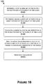
- FIG. 8 is a flow diagram showing a method for obstacle avoidance, in accordance with some embodiments of the present disclosure.
- FIG. 9A is an example visualization of safety procedures, in accordance with some embodiments of the present disclosure.
- FIG. 9B is another example visualization of safety procedures of first vehicles relative to a second vehicle, in accordance with some embodiments of the present disclosure.
- FIG. 9C is another example visualization of projections of safety procedures of first vehicles relative to a second vehicle, in accordance with some embodiments of the present disclosure.
- FIG. 9D is another example visualization of projections of safety procedures of first vehicles relative to a second vehicle, in accordance with some embodiments of the present disclosure.
- FIG. 9E is another example visualization of projections of safety procedures of first vehicles relative to a second vehicle, in accordance with some embodiments of the present disclosure.
- FIG. 10 is a flow diagram showing a method for trajectory visualization techniques, in accordance with some embodiments of the present disclosure.
- FIG. 11A is an illustration of an example autonomous vehicle, in accordance with some embodiments of the present disclosure.
- FIG. 11B is an example of camera locations and fields of view for the example autonomous vehicle of FIG. 11A , in accordance with some embodiments of the present disclosure
- FIG. 11C is a block diagram of an example system architecture for the example autonomous vehicle of FIG. 11A , in accordance with some embodiments of the present disclosure
- FIG. 11D is a system diagram for communication between cloud-based server(s) and the example autonomous vehicle of FIG. 11A , in accordance with some embodiments of the present disclosure.
- FIG. 12 is a block diagram of an example computing device suitable for use in implementing some embodiments of the present disclosure.
- Systems and methods are disclosed related to analyzing safety procedures of a vehicle and objects in an environment for obstacle avoidance.
- the present disclosure may be described with respect to an example autonomous vehicle 102 (alternatively referred to herein as “vehicle 102 ” or “autonomous vehicle 102 ”), an example of which is described in more detail herein with respect to FIGS. 11A-11D .
- vehicle 102 alternatively referred to herein as “vehicle 102 ” or “autonomous vehicle 102 ”
- autonomous vehicle 102 autonomous vehicle 102
- FIGS. 11A-11D autonomous vehicle 102
- the present disclosure may be described with respect to an autonomous vehicle system 100 , this is not intended to be limiting, and the methods and processes described herein may be implemented on systems including additional or alternative structures, components, and/or architectures without departing from the scope of the present disclosure.
- the present disclosure relates to at least a portion of a system for controlling an autonomous vehicle safely, without the requirement of human supervision. More specifically, the current disclosure relates to methods and processes for an obstacle avoidance level of an autonomous driving software stack (e.g., in some implementations, the last or lowest level of the autonomous driving software stack prior to an actuation layer) that is used help guarantee that a collision between a vehicle and objects in the environment does not occur.
- the obstacle avoidance mechanisms described herein are executed even if their execution involves disobeying traffic laws or other rules of the road generally obeyed by a higher level of the autonomous driving software stack (e.g., a planning layer or a control layer).
- conventional systems generally analyze sensor information corresponding to what is in front of, or behind, the vehicle (e.g., along a longitudinal axis of the vehicle) separate and distinct from analyzing sensor information corresponding to what is to the side of the autonomous vehicle (e.g., along a lateral axis of the vehicle).
- unnecessary constraints on controlling the vehicle may be created and, especially when used by autonomous vehicles, may restrict the autonomous vehicles from performing natural and/or required vehicle maneuvers (e.g., maneuvering into an adjacent lane in slow traffic when another vehicle is to the side of the autonomous vehicle).
- a safety procedure may be executed when certain scenarios are perceived regardless of whether safer options, other than the safety procedure, exist.
- there may be exceptions to executing the safety procedure that may be specified by rules and moderated by input information, such as lane structure, path structures based on map information, and/or the like.
- a reliance may still exist on an exception being available for the scenario perceived by the vehicle in order for the vehicle to abort the safety procedure and to execute another action(s). That said, it may be highly improbable that there is an exception built for every scenario and, as a result, when an exception is not available, the safety procedure may be implemented even though it presents a more unsafe outcome.
- these conventional systems may implement the safety procedure or one of the exceptions thereof even though other, safer actions, are available.
- the present disclosure in contrast to conventional systems, includes a system that may calculate a safety potential (e.g., a measure of a likelihood or imminence of a collision occurring) for a safety procedure, use the safety potential as a baseline, and then determine whether another action or set of actions can be implemented to adjust the safety potential to decrease the likelihood and/or imminence (and as a result, the likelihood, in some scenarios) of a collision occurring.
- a safety potential e.g., a measure of a likelihood or imminence of a collision occurring
- exceptions and rules such as those used in conventional systems, are not required, because the system is evaluating at each situation, determining the safety potential for the safety procedure, and then determining whether to implement the safety procedure or an action(s) that surpasses the safety potential associated with the safety procedure.
- the current system may determine a state (e.g., location, velocity, orientation, yaw rate, etc.) of a vehicle, vehicle information (e.g., width, length, etc.) and use the state and the vehicle information to determine points in space-time that the vehicle occupies.
- a state e.g., location, velocity, orientation, yaw rate, etc.
- vehicle information e.g., width, length, etc.
- the system may then determine a safety procedure for the vehicle (e.g., at high speeds, lining up with a current lane and braking until completely stopped, at low speeds, pulling to the side of road then braking, etc.) based on the scenario (e.g., type of road, such as highway or surface street, the velocity of the vehicle, the other objects in the environment, etc.), and may generate a virtual representation of points in space-time (e.g., in three-dimensions, two dimensions for space, and one dimension for time) that the vehicle will occupy (e.g., a vehicle-occupied trajectory(ies)) when executing the safety procedure.
- a safety procedure for the vehicle e.g., at high speeds, lining up with a current lane and braking until completely stopped, at low speeds, pulling to the side of road then braking, etc.
- scenario e.g., type of road, such as highway or surface street, the velocity of the vehicle, the other objects in the environment, etc.
- the vehicle-occupied trajectory(ies) may include a range of possible implementations of the safety procedure (e.g., the trajectory when implementing the hardest braking and avoiding a collision, the trajectory when implementing the slowest braking while still avoiding a collision, and any trajectories in-between where braking is neither the hardest nor slowest).
- a trajectory herein, may include more than one trajectory (e.g., trajectories), that may include each of the trajectories associated with different implementations (e.g., profiles) of the safety procedure.
- a union of two or more vehicle-occupied trajectories may be determined, such as by using a convex hull of an image of the object or vehicle at each time slice.
- Each of the points within the vehicle-occupied trajectory(ies) may be referred to as a claimed set of points.
- the current system may determine states and safety procedures for each object (perceived and unperceived, static and moving) in the environment.
- the system may then generate virtual representations of the points in space-time the objects will occupy (e.g., object-occupied trajectories) when executing their respective safety procedures.
- the system may use rules that are based on reasonable expectations. For example, when an intersection is occluded in some way, the system may generate an unperceived object as a car traveling at a reasonable speed approaching the intersection from the occluded direction. As another example, if two cars are parked on the side of the street, the system may generate an unperceived object as a person between the two cars.
- the unperceived objects may be included in the analysis by the system in addition to the perceived objects (e.g., objects identified based on sensor data from sensors of the vehicle).
- the system may then monitor the vehicle-occupied trajectory(ies) in view of the object-occupied trajectories to determine if an intersection or overlap occurs (in some examples, with a safety margin built in). Once it is determined that an intersection occurs, the system may implement a “safety force field” and seek to “repel” the vehicle from the object(s) by implementing the safety procedure or by implementing another set of controls that has been determined to have an equal or lesser associated likelihood and/or imminence of causing an actual collision between the vehicle and any of the objects.
- the system may calculate a safety potential associated with the safety procedure (in some examples, the safety potential is a representation of the degree of overlap between the vehicle-occupied trajectory(ies) and the object-occupied trajectory(ies)—e.g., the area or volume of overlap between the two), and may use the safety potential as a baseline (e.g., no action taken should increase the likelihood or imminence of a collision when compared to the safety procedure).
- the safety potential may be determined using a function where, when no overlap is detected, the function is zero, and is high or maximum at the time of first collision.
- the safety potential may be referred to as measuring imminence of a collision in addition to, or alternatively from, measuring a likelihood of a collision.
- the system may then perform a perturbation analysis on an original state of the vehicle (e.g., using the chain rule), to determine whether another set of controls (e.g., another action, such as speeding up instead of braking, turning left instead of right, etc.) results in a safety potential that is indicative of an equal or lower likelihood of collision between the vehicle and any of the objects as compared to the safety potential when implementing the safety procedure.
- another set of controls e.g., another action, such as speeding up instead of braking, turning left instead of right, etc.
- the system may cease implementing the safety procedure or the other action(s), and give control back to a higher layer of the autonomous driving software stack (e.g., a planning layer and/or control layer) associated with controlling the vehicle according to normal driving protocols (e.g., obeying rules of the road, following the current directions, etc.).
- a higher layer of the autonomous driving software stack e.g., a planning layer and/or control layer
- normal driving protocols e.g., obeying rules of the road, following the current directions, etc.
- the action(s) selected may depend on what the higher layer of the stack originally planned to implement (e.g., proposed controls representative of a planned trajectory), and the system may select the closest safe controls and/or safe trajectories to the original planned action(s) (e.g., using one or more metrics).
- FIG. 1 is a block diagram of an example autonomous vehicle system 100 , in accordance with some embodiments of the present disclosure. It should be understood that this and other arrangements described herein are set forth only as examples. Other arrangements and elements (e.g., machines, interfaces, functions, orders, groupings of functions, etc.) can be used in addition to or instead of those shown, and some elements may be omitted altogether. Further, many of the elements described herein are functional entities that may be implemented as discrete or distributed components or in conjunction with other components, and in any suitable combination and location. Various functions described herein as being performed by entities may be carried out by hardware, firmware, and/or software. For instance, various functions may be carried out by a processor executing instructions stored in memory.
- the autonomous vehicle system 100 may include an example autonomous vehicle 102 , a server(s) 104 , and/or one or more objects 106 .
- one or more of the autonomous vehicle 102 , the server(s) 104 , and/or the one or more objects 106 may include similar components, features, and/or functionality as computing device 1200 of FIG. 12 , described in more detail herein.
- the components, features, and/or functionality of the autonomous vehicle 102 described with respect to FIG. 1 may be implemented using the features, components, and/or functionality described in more detail herein with respect to FIGS. 11A-11D .
- the components, features, and/or functionality of the server(s) 104 described with respect to FIG. 1 may be implemented using the features, components, and/or functionality described in more detail herein with respect to FIG. 11D .
- the autonomous vehicle 102 may include a sensor manager 108 .
- the sensor manager 108 may manage and/or abstract sensor data from sensors of the vehicle 102 .
- the sensor data may be generated (e.g., perpetually, at intervals, based on certain conditions) by global navigation satellite system (GNSS) sensor(s) 1158 , RADAR sensor(s) 1160 , ultrasonic sensor(s) 1162 , LIDAR sensor(s) 1164 , inertial measurement unit (IMU) sensor(s) 1166 , microphone(s) 1196 , stereo camera(s) 1168 , wide-view camera(s) 1170 , infrared camera(s) 1172 , surround camera(s) 1174 , long range and/or mid-range camera(s) 1198 , and/or other sensor types.
- GNSS global navigation satellite system
- RADAR sensor(s) 1160 e.g., ultrasonic sensor(s) 1162 , LIDAR sensor(s) 1164 , in
- the sensor manager 108 may receive the sensor data from the sensors in different formats (e.g., sensors of the same type, such as LIDAR sensors, may output sensor data in different formats), and may be configured to convert the different formats to a uniform format (e.g., for each sensor of the same type). As a result, other components, features, and/or functionality of the autonomous vehicle 102 may uses the uniform format, thereby simplifying processing of the sensor data.
- the sensor manager 108 may use a uniform format to apply control back to the sensors of the vehicle 102 , such as to set frame rates or to perform gain control.
- the sensor manager 108 may also update sensor packets corresponding to the sensor data with timestamps to help inform processing of the sensor data by various components, features, and functionality of the autonomous vehicle system 100 .
- a world model manager 122 may be used to generate, update, and/or define a world model.
- the world model manager 122 may use information generated by and received from an obstacle perceiver 110 , a path perceiver 112 , a wait perceiver 114 , and/or a map perceiver 116 .
- the world model may be defined, at least in part, based on affordances for obstacles, paths, and wait conditions that can be perceived in real-time or near real-time by the obstacle perceiver 110 , the path perceiver 112 , the wait perceiver 114 , and/or the map perceiver 116 .
- the world model manager 122 may continually update the world model based on newly generated and/or received inputs (e.g., data) from the obstacle perceiver 110 , the path perceiver 112 , the wait perceiver 114 , the map perceiver 116 , and/or other components of the autonomous vehicle system 100 .
- inputs e.g., data
- the world model may be used to help inform planning component(s) 124 (e.g., associated with a planning layer of an autonomous driving software stack or architecture), control component(s) 126 (e.g., associated with a control layer of the autonomous driving software stack), obstacle avoidance component(s) 128 (e.g., associated with an obstacle or collision avoidance layer of the autonomous driving software stack, and/or actuation component(s) 130 (e.g., associated with an actuation layer of the autonomous driving software stack).
- planning component(s) 124 e.g., associated with a planning layer of an autonomous driving software stack or architecture
- control component(s) 126 e.g., associated with a control layer of the autonomous driving software stack
- obstacle avoidance component(s) 128 e.g., associated with an obstacle or collision avoidance layer of the autonomous driving software stack
- actuation component(s) 130 e.g., associated with an actuation layer of the autonomous driving software stack
- the obstacle perceiver 110 may perform obstacle perception that may be based on where the vehicle 102 is allowed to drive or is capable of driving, and how fast the vehicle 102 can drive without colliding with an obstacle (e.g., an object 106 , such as a structure, entity, vehicle, etc.) that is sensed by the sensors of the vehicle 102 .
- an obstacle e.g., an object 106 , such as a structure, entity, vehicle, etc.
- the object(s) 106 may include other vehicles (e.g., cars, trucks, motorcycles, busses, etc.) that may be capable of communicating with the vehicle 102 directly and/or indirectly.
- the object(s) 106 may communicate directly with the vehicle 102 via vehicle-to-vehicle communication, such as over one or more network types (e.g., local area wireless networks).
- the object(s) 106 may communicate indirectly with the vehicle 102 , such as via the server(s) 104 and one or more network(s) (e.g., over a cellular network). In such examples, the object(s) 106 may communicate with the server(s) 104 and the server(s) 104 may communicate with the vehicle 102 , and vice versa. The information received from and/or about the object(s) 106 may also be used by the path perceiver 112 , the map perceiver 116 , and/or other component, features, and/or functionality of the vehicle 102 .
- the path perceiver 112 may perform path perception, such as by perceiving nominal paths that are available in a particular situation. In some examples, the path perceiver 112 further takes into account lane changes for path perception.
- a lane graph may represent the path or paths available to the vehicle 102 , and may be as simple as a single path on a highway on-ramp. In some examples, the lane graph may include paths to a desired lane and/or may indicate available changes down the highway (or other road type), or may include nearby lanes, lane changes, forks, turns, cloverleaf interchanges, merges, and/or other information.
- the wait perceiver 114 may be responsible to determining constraints on the vehicle 102 as a result of rules, conventions, and/or practical considerations.
- the rules, conventions, and/or practical considerations may be in relation to traffic lights, multi-way stops, yields, merges, toll booths, gates, police or other emergency personnel, road workers, stopped busses or other vehicles, one-way bridge arbitrations, ferry entrances, etc.
- the wait perceiver 114 may be responsible for determining longitudinal constraints on the vehicle 102 that require the vehicle to wait or slow down until some condition is true.
- wait conditions arise from potential obstacles, such as crossing traffic in an intersection, that may not be perceivable by direct sensing by the obstacle perceiver 110 , for example (e.g., by using sensor data from the sensors, because the obstacles may be occluded from field of views of the sensors).
- the wait perceiver may provide situational awareness by resolving the danger of obstacles that are not always immediately perceivable through rules and conventions that can be perceived and/or learned.
- the wait perceiver 114 may be leveraged to identify potential obstacles and implement one or more controls (e.g., slowing down, coming to a stop, etc.) that may not have been possible relying solely on the obstacle perceiver 110 .
- the map perceiver 116 may include a mechanism by which behaviors are discerned, and in some examples, to determine specific examples of what conventions are applied at a particular locale. For example, the map perceiver 116 may determine, from data representing prior drives or trips, that at a certain intersection there are no U-turns between certain hours, that an electronic sign showing directionality of lanes changes depending on the time of day, that two traffic lights in close proximity (e.g., barely offset from one another) are associated with different roads, that in Rhode Island, the first car waiting to make a left turn at traffic light breaks the law by turning before oncoming traffic when the light turns green, and/or other information. The map perceiver 116 may inform the vehicle 102 of static or stationary infrastructure objects and obstacles. The map perceiver 116 may also generate information for the wait perceiver 114 and/or the path perceiver 112 , for example, such as to determine which light at an intersection has to be green for the vehicle 102 to take a particular path.
- information from the map perceiver 116 may be sent, transmitted, and/or provided to the server(s) 104 (e.g., to a map manager 118 of the server(s) 104 ), and information from the server(s) 104 may be sent, transmitted, and/or provided to the map perceiver 116 and/or a localization manager 120 of the vehicle 102 .
- the map manager 118 may include a cloud mapping application that is remotely located from the vehicle 102 and accessible by the vehicle 102 over a network(s) (e.g., the network(s) 1190 of FIG. 11D ).
- the map perceiver 116 and/or the localization manager 120 of the vehicle 102 may communicate with the map manager 118 and/or one or more other components or features of the server(s) 104 to inform the map perceiver 116 and/or the localization manager 120 of past and present drives or trips of the vehicle 102 , as well as past and present drives or trips of other vehicles.
- the map manager 118 may provide mapping outputs (e.g., map data) that may be localized by the localization manager 120 based on a particular location of the vehicle 102 , and the localized mapping outputs may be used by the world model manager 122 to generate and/or update the world model.
- the planning component(s) 124 may include a route planner, a lane planner, a behavior planner, and a behavior selector, among other components, features, and/or functionality.
- the route planner may use the information from the map perceiver 116 , the map manager 118 , and/or the localization manger 120 , among other information, to generate a planned path that may consist of GNSS waypoints (e.g., GPS waypoints).
- the waypoints may be representative of a specific distance into the future for the vehicle 102 , such as a number of city blocks, a number of kilometers, a number of feet, a number of miles, etc., that may be used as a target for the lane planner.
- the lane planner may use the lane graph (e.g., the lane graph from the path perceiver 112 ), object poses within the lane graph (e.g., according to the localization manager 120 ), and/or a target point and direction at the distance into the future from the route planner as inputs.
- the target point and direction may be mapped to the best matching drivable point and direction in the lane graph (e.g., based on GNSS and/or compass direction).
- a graph search algorithm may then be executed on the lane graph from a current edge in the lane graph to find the shortest path to the target point.
- the behavior planner may determine the feasibility of basic behaviors of the vehicle 102 , such as staying in the lane or changing lanes left or right, so that the feasible behaviors may be matched up with the most desired behaviors output from the lane planner. For example, if the desired behavior is determined to not be safe and/or available, a default behavior may be selected instead (e.g., default behavior may be to stay in lane when desired behavior or changing lanes is not safe).
- the behavior planner may consider more free-form trajectories by taking into account a dynamic occupancy grid (e.g., a grid indicative of objects, stationary and moving, in the vicinity of the vehicle 102 , as determined by sensors of the vehicle 102 and/or map information), in addition to the other inputs of the planning component(s) 124 described herein.
- the behavior planner in such examples, may generate a number of different paths (e.g., fanning out from a nominal or desired path for the behavior in question), such as paths that are slightly laterally offset with varying amounts of turning. The paths may then be compared against the dynamic occupancy grid to check for safety and desirability, including checking for comfort (e.g., to the passenger(s)) and agreement with the nominal path.
- the behavior selector may perform logic based on the output of the behavior planner and the request from the lane planner to determine which behavior to execute. For example, if the lane planner requests that the vehicle 102 stay in the lane, the behavior selector may maintain the vehicle 102 in the current lane. If a lane change is requested by the lane planner, the lane change may be checked against the lane graph, and executed if the behavior planner determines that the lane change is safe and doesn't require heavy braking (e.g., that may cause discomfort to the passenger(s)). The path through a lane change may be the path produced by the behavior planner, when the behavior selector has confirmed the lane change is appropriate.
- the control component(s) 126 may follow a trajectory or path (lateral and longitudinal) that has been received from the behavior selector of the planning component(s) 124 as closely as possible and within the capabilities of the vehicle 102 .
- the control component(s) 126 may use tight feedback to handle unplanned events or behaviors that are not modeled and/or anything that causes discrepancies from the ideal (e.g., unexpected delay).
- the control component(s) 126 may use a forward prediction model that takes control as an input variable, and produces predictions that may be compared with the desired state (e.g., compared with the desired lateral and longitudinal path requested by the planning component(s) 124 ).
- the control(s) that minimize discrepancy may be determined.
- temporal filtering may be used to reduce oscillations experienced from delays that are not modeled (e.g., when no temporal element is used).
- Some examples may use model predictive control, such as Euler forward integration (or another form of forward integration) of the differential equations that model the motion of the vehicle 102 . In such examples, discrepancies may be measured at multiple points in the future and balanced by a goal function.
- a Proportional Integral Derivative (PID) controller may be used with lookup tables based on the relative distance, relative velocity, and velocity of the vehicle 102 .
- Comfort limits may be put on acceleration (e.g., 5 m/s 2 ) and jerk, and/or speed dependent limits may be put on steering angle and steering angle rate.
- the planning component(s) 124 and the control component(s) 126 are illustrated separately, this is not intended to be limiting.
- the delineation between the planning component(s) 124 and the control component(s) 126 may not be precisely defined.
- at least some of the components, features, and/or functionality attributed to the planning component(s) 124 may be associated with the control component(s) 126 , and vice versa.
- the obstacle avoidance component(s) 128 may aid the autonomous vehicle 102 in avoiding collisions with objects (e.g., moving and stationary objects).
- the obstacle avoidance component(s) 128 may include a computational mechanism at a “primal level” of obstacle avoidance, and may act as a “survival brain” or “reptile brain” for the vehicle 102 .
- the obstacle avoidance component(s) 128 may be used independently of components, features, and/or functionality of the vehicle 102 that is required to obey traffic rules and drive courteously. In such examples, the obstacle avoidance component(s) may ignore traffic laws, rules of the road, and courteous driving norms in order to ensure that collisions do not occur between the vehicle 102 and any objects.
- the obstacle avoidance layer may be a separate layer from the rules of the road layer, and the obstacle avoidance layer may ensure that the vehicle 102 is only performing safe actions from an obstacle avoidance standpoint.
- the rules of the road layer may ensure that vehicle obeys traffic laws and conventions, and observes lawful and conventional right of way (as described herein).
- Both the obstacle avoidance layer and the rules of the road layer may include perception component(s) and planning and control component(s).
- Core obstacle avoidance perception reliability may be ensured by multi-way redundancy, such as cameras, RADAR sensors, LIDAR sensors, etc. By separating out the obstacle avoidance layer, as is done in some examples, independent validation to high levels of reliability may be allowed, providing a foundation for safety.
- the rules of the road layer may be validated similarly, with ground truth measurements for the perception and right-of-way determination, and mathematical correctness validation of yield planning.
- the vehicle 102 may include at least one safety procedure and each of the objects 106 may include at least one safety procedure.
- the obstacle avoidance component(s) 128 may then operate under the assumption that the vehicle 102 and the objects 106 in the environment each include a respective safety procedure.
- the safety procedures for the vehicle 102 and/or the objects 106 may include procedures for straightening or fixing the steering wheel and coming to a complete stop, pulling to the side of the road and then coming to a complete stop, and/or another safety procedure.
- Obstacle avoidance may be based on an assumption that all actors (e.g., the vehicle 102 and the objects 106 ) should perform their safety procedures before the trajectory(ies) resulting from their safety procedures intersects with that of another actor. With this approach, a collision should not occur unless one of the actors did not do what was required. When a collision occurs, fault may be clearly determined because at least one of the actors likely did not follow their safety procedure.
- actors e.g., the vehicle 102 and the objects 106
- the actor that did not perform its safety procedure before or during the time that the safety procedures intersect may be at fault, unless one of the actors that did perform its safety procedure was not traveling at a reasonable speed (e.g., as a function of the speed limit) at the time of its performance, in which case the fault may be attributed to the actor that was not traveling a reasonable speed.
- a reasonable speed e.g., as a function of the speed limit
- a trajectory(ies) resulting from a safety procedure may be referred to as a safety force field, and when the trajectories (or safety force fields) of two or more actors intersect, the safety force fields may repel one another, and each actor may be required to implement their respective safety procedure, or another (alternative) procedure determined to have a lower likelihood or imminence of collision than the safety procedure. For example, an actor should not engage in its safety procedure when the safety procedure may not help minimize risk of a collision, such as to not brake when being tailgated.
- the autonomous vehicle system 100 may determine whether the safety procedure is helpful (e.g., minimizes risk), and if it is not (at least as helpful in minimizing risk as another procedure), then another (alternative) procedure may be undertaken. For example, if the safety procedure for the vehicle 102 were to fix steering and come to a complete stop, but the vehicle 102 is being tailgated, the vehicle 102 may instead turn toward a side of the road and come to a complete stop, thereby avoiding the tailgating actor.
- the safety procedure e.g., minimizes risk
- another (alternative) procedure may be undertaken. For example, if the safety procedure for the vehicle 102 were to fix steering and come to a complete stop, but the vehicle 102 is being tailgated, the vehicle 102 may instead turn toward a side of the road and come to a complete stop, thereby avoiding the tailgating actor.
- the obstacle avoidance component(s) 128 may be located after the control component(s) 126 in an autonomous driving software stack (e.g., in order to receive desired controls from the control component(s) 126 , and test the controls for obstacle avoidance).
- an autonomous driving software stack e.g., in order to receive desired controls from the control component(s) 126 , and test the controls for obstacle avoidance.
- the obstacle avoidance component(s) 128 are shown stacked on top of (e.g., with respect to an autonomous driving software stack) the planning component(s) 124 and the control component(s) 126 , this is not intended to be limiting.
- the obstacle avoidance component(s) 128 may be additionally or alternatively implemented prior to either of the planning component(s) 124 or the control component(s) 126 , prior to the control component(s) 126 but after the planning component(s) 124 , as part of or integral to the planning component(s) 124 and/or the control component(s) 126 , as part of the obstacle perceiver 110 , and/or at a different part of an autonomous driving software stack or architecture depending on the embodiment.
- the obstacle avoidance component(s) 128 may be implemented in one or more locations within an autonomous vehicle driving stack or architecture without departing from the scope of the present disclosure.
- the obstacle avoidance component(s) 128 may be implemented as a separate, discrete feature of the vehicle 102 .
- the obstacle avoidance component(s) 128 may operate separately (e.g., in parallel with, prior to, and/or after) the planning layer, the control layer, the actuation layer, and/or other layers of the autonomous driving software stack.
- the obstacle avoidance component(s) 128 may include a state determiner 132 , a safety procedure determiner 134 , a claimed set determiner 136 , a trajectory generator 138 , a safety potential calculator 140 , a control analyzer 142 , and/or one or more additional or alternative components.
- the state determiner 132 may determine a state of the actors (e.g., the vehicle 102 and the objects 106 , static or dynamic) in the environment.
- the state of each actor may generally include a location, a speed, a direction (e.g., direction of travel), a velocity, an acceleration(s) (e.g., scalar, rotational, etc.), and/or other information about the state of the actors.
- the state may encode or represent the position of the actor in two-dimensional space (e.g., (x, y) coordinates), a unit direction of the actor, and/or a scalar velocity of the actor at a point in time.
- the state may encode or represent additional or alternative information, such as rotational velocity (e.g., yaw) and/or scalar acceleration in any direction.
- a state, x A for each actor, may be parameterized as an m-dimensional state vector, represented as follows, in equation (1): x A ( t ) ⁇ m (1)
- a vector may represent a state trajectory, X A , of the actor (e.g., the state trajectory, X A , may represent or encode each state, x A , of the actor at each time within a period of time).
- the state trajectories may be determined for each of the actors by the state determiner 132 , and the collection of the states (e.g., at any one time) and/or the collection of the state trajectories (e.g., as a function of time) may include a set of state spaces or state trajectories for all actors in the environment.
- the state determiner 132 may determine the state of the vehicle 102 using any combination of sensors, such as the GNSS sensors 1158 , the IMU sensor(s) 1166 , the speed sensor(s) 1144 , the steering sensor(s) 1140 , etc.
- the state determiner 132 may determine and/or infer the state of the objects 106 in the environment using any combination of the stereo camera(s) 1168 , the wide-view camera(s) 1170 , the infrared camera(s) 1172 , the surround camera(s) 1174 , the long range and/or mid-range camera(s) 1198 , the LIDAR sensor(s) 1164 , the RADAR sensor(s) 1160 , the microphone(s) 1196 , the ultrasonic sensor(s) 1162 , and/or other sensors of the vehicle 102 .
- the state of the objects 106 may be determined using wireless communications, such as vehicle-to-vehicle communication, or device-to-vehicle communication, over one or more networks, such as, but not limited to, the network(s) described herein.
- machine learning models such as neural networks (e.g., convolutional neural networks), may be used to determine the states of the actors.
- sensor data from the sensors of the vehicle 102 may be applied to one or more machine learning models in order to aid the vehicle 102 in determining the state of the objects 106 in the environment.
- the autonomous vehicle 102 may be configured to quickly and efficiently execute neural networks, on processed and/or unprocessed data for a variety of functions.
- a convolutional neural network may be used for object detection and identification (e.g., using sensor data from camera(s) of the vehicle 102 ), a convolutional neural network may be used for distance estimation (e.g., using the sensor data from the camera(s) of the vehicle 102 ), a convolutional neural network may be used for emergency vehicle detection and identification (e.g., using sensor data from the microphone(s) of the vehicle 102 ), a convolutional neural network may be used for facial recognition and vehicle owner identification (e.g., using the sensor data from the camera(s) of the vehicle 102 ), a convolutional neural network may be used for identifying and processing security and/or safety related events, and/or other machine learning models may be used.
- any type of convolutional neural networks may be used, including region-based convolutional neural networks (R-CNNs), Fast R-CNNs, and/or other types.
- a control model may be determined for the actors (e.g., by the safety procedure determiner 134 ).
- a control model may be represented as follows, in equation (3):
- control model for an actor may represent a derivative of the state of the actor, x A , with respect to time, t, and control parameter(s), c.
- the control model may be formulated locally as an explicit differential equation with control parameter(s), c, that may model user input, such as steering, braking, and acceleration.
- control model for an actor may be expressed according to equation (4), below:
- dx A dt [ vd T vbd ⁇ T a ] T ( 4 )
- v is a scalar velocity
- d is unit direction vector
- a is a scalar acceleration amount
- b is a scalar steering parameter
- d ⁇ is the perpendicular to d, generated by flipping the coordinates of d and negating the first coordinate.
- the control parameters may be a, the scalar acceleration amount
- b the scalar steering parameter.
- a control policy may be determined (e.g., by the safety procedure determiner 134 ).
- the control parameters may be a function of the world state, x w (or a perception of the world state based on the sensor data generated by the sensors of the vehicle 102 ), and time, t.
- a control policy may be a function of the joint state space of the world and time into m (where m is the dimension of the state space of the actor) that is smooth and bounded.
- a control policy may be represented as follows, in equation (5):
- a safety procedure may be determined for each actor (e.g., by the safety procedure determiner). For example, as described herein, each actor may be assumed to have a safety procedure, S A .
- the safety procedure may have an associated trajectory(ies) derived from any starting state, X, of the actor.
- the safety procedure may represent the trajectory(ies) of the actor as the actor transitions form the state, X, to an actor state objective (e.g., a final location, where the actor may come to a stop).
- the actor state objective may be determined, in some examples, by analyzing sensor data received from one or more sensors (e.g., of the vehicle 102 ) to determine locations, orientations, and velocities of objects 106 (or other actors) in the environment.
- Control parameters e.g., for steering, braking, accelerating, etc.
- the actors e.g., the vehicle 102 and/or the objects 106
- a set of functions to guide the actor to the actor state objective may be determined.
- the safety procedure may result in a trajectory(ies) that changes smoothly with its starting state (e.g., because the safety procedure may be a continuous deceleration to a stop).
- a safety procedure, S A may be represented as follows, in equation (6):
- the safety procedure for an actor may or may not depend on fixed properties of the world, depending on the embodiment.
- the safety procedure may not depend on the fixed properties of the world, such as road shape or a map.
- the safety procedure may include freezing a direction vector (e.g., by setting a scalar steering parameter, b, to zero), and coming to a complete stop by slowing down by a range of acceleration values [a min , a′] (where a min is minimum acceleration amount or the negative of a maximum braking amount, and a′ is a negative value larger than a min ), to a complete stop.
- This type of safety procedure, S A may be represented by equation (7), below:
- the safety procedure may include braking until reaching a complete stop.
- the safety procedure may include lining up with a current lane (or with the direction of the road, such as when the vehicle 102 is in the middle of a lane change), and then coming to a complete stop (and thus may depend on fixed properties of the world, such as lane markings).
- the safety procedure may include the vehicle 102 steering itself to a side of the road as it decelerates to a stop (and thus may depend on the fixed properties of the world).
- one or more neural networks may be used to identify the side of the road and/or to aid in maneuvering the vehicle 102 to the side of the road.
- an HD map 1122 may be used (e.g., using the map perceiver 116 , the map manager 118 , and/or the localization manager 120 ). In such an example, the HD map 1122 may be received over a network(s) 1190 and/or may be embedded in the vehicle 102 .
- the safety procedure may be modified to provide for a certain level of comfort (e.g., maximum comfort) for the passengers of the vehicle (e.g., minimum deceleration or directional change) while still guaranteeing avoidance of a collision.
- a course, trajectory, and/or control sequence may be determined for the vehicle 102 , as the safety procedure, that maximizes comfort and/or minimizes force exerted on passengers while still ensuring that a collision with other objects 106 (e.g., vehicles, entities, structures, etc.) is avoided.
- the safety procedure may be modified to minimize the risk of harm to the passengers in the vehicle and other entities should a collision occur.
- a safety procedure 202 may include an actor 204 (or a shape representing the actor 204 ) coming to a complete stop while maintaining a low or zero lateral rate of change.
- the safety procedure 202 may include driving straight ahead and/or continuing along the current steering circle (which may or may not include a lateral rate of change) until the actor 204 comes to a complete stop.
- the safety procedure 202 may include continuing at the steering angle until a complete stop is reached.
- the safety procedure 202 may include continuing straight until a complete stop is reached (e.g., as illustrated in FIG. 2A ).
- the safety procedures for any actor may include a safety margin (e.g., in addition to, or alternatively from, the safety margin described herein with respect to a size of the actor).
- a safety margin e.g., in addition to, or alternatively from, the safety margin described herein with respect to a size of the actor.
- the safety margin for the safety procedure may increase.
- a width, W 1 of the claimed set of the safety procedure 202 may be less than a width, W 2 , of the claimed set of the safety procedure 202 .
- the width, W 1 may correspond to an earlier time, there may be less margin for error as compared to the time associated with the width, W 2 .
- the safety margin may increase over space-time to account for this error.
- a safety procedure 206 may include the actor 204 (or the shape representing the actor 204 ), during a lane change from a first lane 208 A to a second lane 208 B, aligning itself with the road (e.g., aborting the lane change and lining up with the direction of the road, such as parallel with lane markings 210 A, 210 B, and/or 210 C), and coming to a complete stop.
- the safety procedure may account for the fixed properties of the world (e.g., the lane markings, the direction of the road, etc.).
- the safety procedure 206 may be determined in order to minimize the lateral rate of change (e.g., with respect to the road shape) while still aborting the lane change and realigning the actor 204 with the road.
- a safety procedure 212 may include the actor 204 (or the shape representing the actor 204 ), following the road shape to accommodate for curves in the road and coming to a complete stop. For example, if the actor 204 is already following the road shape, and thus accounting for the fixed properties of the world, the safety procedure 212 may include continuing to follow the road shape (e.g., as defined by the lane markings 210 D and 210 E). Similar to the safety procedure 206 , the safety procedure 212 may be determined in order to minimize the lateral rate of change while continuing to follow the road shape.
- the claimed set determiner 136 may determine a claimed set of the vehicle 102 and the objects 106 in the environment.
- the claimed set for an actor may include an occupied trajectory (e.g., each of the points in space that the actor occupied when following a trajectory) of an actor when the actor applies its safety procedure, S A , starting from state, x A .
- the claimed set determiner 136 may determine an area and/or volume in space occupied by the actor given its state. For example, the autonomous vehicle system 100 may assume that actors move around in and occupy n-dimensional real space, . In some examples, for simplicity, the autonomous vehicle system 100 may use two-dimensional space modeling a top-down view of the real world. In other examples, the autonomous vehicle system 100 may use three-dimensional space. In any example, in order to determine the claimed set, the autonomous vehicle system 100 may first determine occupied sets of each actor, representing a set of points in space that the actor occupies as a function of its state.
- the occupied set, o A for an actor may be determined as follows, in equation (8), below: o A ( x A ) ⁇ n (8) If a point in space is in the occupied set of the actor, the actor may be determined to occupy the point.
- a size e.g., an actual size of the actor
- representative size e.g., a shape around and/or including the actor
- the size or representative size may include an optional safety margin.
- the size of the vehicle 102 may be known (e.g., based on calibration information, vehicle information, vehicle make and model, and/or other parameters).
- the size of the objects 106 may be determined using the sensors and sensor data therefrom (e.g., from the sensor manager 108 ), and/or one or more machine learning models (e.g., convolutional neural networks).
- a shape e.g., a predefined shape, such as a square, polygon, bounding box, cube, circle, oval, ellipse, etc.
- the size of the actor may be determined to be the size of the predefined shape (e.g., including a safety margin, in some examples, as described herein).
- the shape may be a two-dimensional shape (e.g., a rectangle or circle), that serves as a bounding box that encircles the actor at least partially.
- the shape may be a three-dimensional shape (e.g., a cube) that serves as a bounding cube that encircles the actor at least partially.
- the size of the vehicle may be used by the claimed set determiner 136 to determine the points (e.g., (x, y) coordinates) in space that the actor occupies as part of the occupied set, o A .
- the size of the actor, and thus the representative shape corresponding to the size of the actor may be determined such that the size and/or shape fully include the actor, at least in two-dimensions (e.g., laterally and longitudinally).
- the size and/or shape may be determined such that the size and/or shape fully include the actor, at least in two-dimensions (e.g., laterally and longitudinally).
- the claimed set determiner 136 may determine the occupied trajectory(ies), O A , of each actor.
- the occupied trajectory(ies) may include the set of points in space-time that the actor will occupy over time as a function of its trajectory(ies).
- the occupied trajectory(ies), when applying the safety procedure, S A , of the actor may include the claimed set, C A .
- Any points determined to be within the claimed set of an actor are points in space-time that the actor may require to maintain the integrity of its safety procedure.
- the vehicle 102 may analyze each of the claimed sets of the actors to determine if any intersection occurs between them. When an intersection occurs, one or more actions may be taken to account for the intersection (e.g., the safety procedure may be implemented, another action may be implemented, etc., as described herein).
- the claimed set, C A may be determined as follows, in equation (10), below: C A ( x A ) ⁇ n ⁇ T (10) where equation (10) may represent the occupied trajectory(ies) of the actor that results if the actor applies its safety procedure starting from state, x A .
- the claimed set may represent a combination or aggregation of each of the occupied trajectories that result from applying the actor's safety procedure with different parameters.
- the safety procedure may be applied with a maximum braking profile, a minimum braking profile, a braking profile in between the maximum and minimum, a maximum steering profile, a minimum steering profile, a steering profile in between the maximum and minimum, and/or in other ways.
- the claimed set may include the occupied trajectories for any number of different applications (e.g., for each different application) of the safety procedure, combined or aggregated.
- the claimed set may represent the safety procedure with a first braking profile for coming to a complete stop more quickly than a second braking profile, and may represent the safety procedure with the second braking profile for coming to a complete stop more slowly (e.g., than the first braking profile) while still avoiding a collision.
- thresholds or bounds may be set and/or determined to define the first braking profile (e.g., a defined maximum or upper bounded braking profile) and the second braking profile (e.g., a defined minimum or lower bounded braking profile).
- the claimed set may represent each of the points in space-time occupied by the actor by the safety procedure applied with the first braking profile, the second braking profile, and the points in space-time occupied by the actor that fall between first and second braking profiles (e.g., as illustrated in and described with respect to FIGS. 3C-3E ).
- the thresholds or bounds for generating the claimed set may be different.
- the thresholds or bounds may be defined, without limitation, based on percentages (e.g., braking intensity percentages) and/or time (e.g., time to come to a complete stop, such as based on a current speed or velocity).
- the first braking profile may include a 95% braking intensity and the second braking profile may include an 85% braking intensity.
- the first braking profile may include coming to a stop within three seconds (e.g., slowing down by an average of twenty mph per second), while the second braking profile may include coming to a stop within four seconds (e.g., slowing down by an average of fifteen mph per second).
- the first braking profile may include one second for every ten mph the vehicle 102 is traveling based on a current state, x A , of the vehicle 102
- the second braking profile may include one second for every fifteen mph the vehicle 102 is traveling based on a current state, X A , of the vehicle 102 .
- the first braking profile may include coming to a stop within three seconds
- the second braking profile may include coming to a stop within four seconds.
- the claimed set may represent the safety procedure with a first steering profile (e.g., a defined maximum steering profile) for reaching a lateral location (e.g., the side of the road, lining up with the road, etc.) more quickly than a second steering profile, and may represent the safety procedure with the second steering profile for reaching the lateral location more slowly than the first steering profile.
- a first steering profile e.g., a defined maximum steering profile
- a lateral location e.g., the side of the road, lining up with the road, etc.
- thresholds or bounds may be set and/or determined to define the first steering profile (e.g., a defined maximum or upper bounded steering profile) and the second braking profile (e.g., a defined minimum or lower bounded steering profile).
- the claimed set may represent each of the points in space-time occupied by the actor by the safety procedure applied with the first steering profile, the second steering profile, and the points in space-time occupied by the actor that fall between the first and second steering profiles.
- the thresholds or bounds for generating the claimed set may be different.
- the steering profiles may also be based on percentages (e.g., percentages of steering angle intensity) and/or time (e.g., amount of time to reach the lateral position).
- the vehicle 102 may be driving toward a static object 302 (where the driving direction is represented in one dimension in the space-time plot of FIG. 3A ).
- the vehicle 102 when not executing a safety procedure, may have an occupied trajectory 304 that results in the vehicle 102 colliding with the static object 302 (e.g., the vehicle 102 does not implement a safety procedure, but rather continues driving along the same path at the same speed until colliding with the object).
- the static object 302 is fixed along the space dimension in the space-time plot because the static object 302 does not move.
- a bounding polygon may be used to represent the size of the vehicle 102 (e.g., a bounding polygon extending from the front to the back of the vehicle 102 , between bounding lines 316 A and 316 B).
- a safety procedure may be implemented, such as to brake until the vehicle 102 comes to a complete stop prior to colliding with the static object 302 .
- the trajectory generator 138 may generate the trajectory 306 , represented by a corresponding claimed set as determined by the claimed set determiner 136 , corresponding to the safety procedure, and the vehicle 102 may implement the safety procedure at time, TI, such that the vehicle 102 stops just prior to colliding with the static object 302 .
- the trajectory generator 138 may persistently project the trajectory 306 (e.g., representing the claimed set of the trajectory of the safety procedure) into space until the trajectory 306 is determined to almost intersect the static object 302 (e.g., at time, TI), and then the vehicle 102 may implement the safety procedure by actuating the brakes at an intensity that corresponds to the safety procedure (e.g., an intensity that will stop the vehicle 102 prior to colliding with the static object 302 , with some margin for error, depending on the embodiment).
- the trajectory 306 may correspond to a second braking profile (e.g., defined minimum or lower bounded braking profile).
- the trajectory generator 138 may generate the trajectories 306 and 308 , represented by the corresponding claimed set as determined by the claimed set determiner 136 , that correspond to a safety procedure implemented using two different braking profiles (e.g., the claimed set may include each of the points in space-time occupied by the vehicle 102 if the vehicle 102 were to implement both the first trajectory 306 , the second trajectory 308 , and/or any trajectory in-between).
- the trajectory 306 may include a first braking profile (e.g., a defined minimum or lower bounded braking profile) and the trajectory 308 may include a second braking profile (e.g., a defined maximum or upper bounded braking profile).
- the vehicle 102 may implement the safety procedure just prior to the trajectory 306 colliding with the static object 302 (e.g., at time, TI).
- the trajectory generator 138 may persistently project the trajectory 306 and/or 308 (as represented by the corresponding claimed set) into space-time until the trajectory 306 (or 308 , in some examples) is determined to almost intersect the static object 302 , and then the vehicle 102 may implement the safety procedure by actuating the brakes at an intensity that corresponds to the chosen braking profile for the safety procedure.
- a property of the claimed set may be that the claimed set does not grow over time when applying the safety procedure.
- the minimum (or safety) braking profile and the maximum braking profile may be defined such that the claimed set is not increasing (although the claimed set may decrease).
- the claimed set may not increase.
- the trajectory generator 138 may generate the trajectories 306 and 308 for the vehicle 102 , and may generate the trajectories 312 and 314 for the object 106 (which may be another vehicle, in this example).
- the trajectories 312 and 314 for the object 106 may be based on a bounding polygon, similar to that of the vehicle 102 , with a size extending between bounding lines 318 A and 318 B.
- the trajectory 312 may include a braking profile corresponding to a safety procedure (e.g., similar to the trajectory 306 for the vehicle 102 ) determined for the object 106 (e.g., based on a state, a control model, a control policy, a type, a size, and/or other information of the object 106 as perceived and/or determined by the vehicle 102 ).
- the trajectory 314 may include a maximum braking profile corresponding to a more aggressive braking profile for the safety procedure, similar to that of the trajectory 308 of the vehicle 102 .
- the points in space-time occupied by the projection of the trajectories 306 and 308 may include the claimed set of the vehicle 102
- the points in space-time occupied by the projection of the trajectories 312 and 314 may include the claimed set of the object 106 .
- the vehicle 102 moves, in the example of FIG. 3D , toward the vehicle 102 , as the vehicle 102 follows the trajectory 304 (e.g., a driving trajectory prior to intersection or near-intersection of the trajectories 306 and 312 ) and the object 106 follows the trajectory 310 (e.g., a driving trajectory prior to the intersection or near intersection of the trajectories 306 and 312 ), the vehicle 102 and the object 106 are approaching one another.
- the trajectory 304 e.g., a driving trajectory prior to intersection or near-intersection of the trajectories 306 and 312
- the object 106 follows the trajectory 310 (e.g., a driving trajectory prior to the intersection or near intersection of the trajectories 306 and 312 )
- the vehicle 102 and the object 106 are approaching one another.
- the vehicle 102 may implement the safety procedure corresponding to the trajectory 306 , the trajectory 308 , and/or another trajectory in between the two.
- the goal may be that the object 106 also implements its safety procedure according to the trajectory 312 , the trajectory 314 , and/or another trajectory between the two, at the same time or within an amount of time that allows the object 106 to stop prior to collision with the vehicle 102 .
- the fault may be attributed to the object 106 because the vehicle 102 , at least, did not contribute to the likelihood or imminence of collision.
- the vehicle 102 may be moving in a similar direction.
- the trajectory 304 e.g., a driving trajectory prior to intersection or near-intersection of the trajectories 306 and 314 and/or 312
- the object 106 follows the trajectory 310 (e.g., a driving trajectory prior to the intersection or near intersection of the trajectories 306 and 314 and/or 312 )
- the vehicle 102 and the object 106 may be moving in a similar direction.
- the vehicle 102 may implement the safety procedure corresponding to the trajectory 306 , the trajectory 308 , and/or another trajectory in between the two.
- the goal may be that the object 106 also implements its safety procedure according to the trajectory 312 , the trajectory 314 , and/or another trajectory between the two, at the same time or within an amount of time that allows the object 106 to stop prior to collision with the vehicle 102 .
- Yet another example includes the vehicle 102 , a first object 106 A (e.g., a vehicle, in this example), and a second object 106 B (e.g., a vehicle, in this example) in an environment 326 .
- the trajectories may occupy a three-dimensional space (e.g., a volume) in space-time within the environment 326 .
- the trajectories may include a longitudinal distance (e.g., a braking or stopping distance), a lateral change (e.g., a steering change), and/or a vertical space (e.g., from the ground plane to a top of a bounding polygon or other shape representative of the occupied set of the actor) occupied by the actors (e.g., the vehicle 102 , the first object 106 A, and the second object 106 B) if the actors were to implement their respective safety procedures.
- a longitudinal distance e.g., a braking or stopping distance
- a lateral change e.g., a steering change
- a vertical space e.g., from the ground plane to a top of a bounding polygon or other shape representative of the occupied set of the actor occupied by the actors (e.g., the vehicle 102 , the first object 106 A, and the second object 106 B) if the actors were to implement their respective safety procedures.
- the trajectories may be analyzed as solid volumes with lengths that increase with velocity (e.g., the faster the actor is moving, the longer the trajectory(ies) and the corresponding points in space-time included in the occupied sets), and the actors may be characterized as driving around with these volumes attached to them (e.g., protruding from them) while performing collision analysis for the volumes (e.g., the trajectories) instead of performing collision analysis on their actual shape.
- velocity e.g., the faster the actor is moving, the longer the trajectory(ies) and the corresponding points in space-time included in the occupied sets
- the actors may be characterized as driving around with these volumes attached to them (e.g., protruding from them) while performing collision analysis for the volumes (e.g., the trajectories) instead of performing collision analysis on their actual shape.
- the volumes or trajectories may be thought of as frozen once an intersection, overlap, or near intersection or overlap is determined between the volumes in space-time and, because there are both lateral and longitudinal dimensions, and shared geometry between the vehicle 102 and the object(s) 106 may not be allowed, the vehicle 102 may be free from collisions (or at least may not contribute to a likelihood of a collision, because other actors actions are outside of the control of the vehicle 102 ).
- the trajectory generator 138 of the vehicle 102 may generate the vehicle-occupied trajectory(ies) 320 representative of the safety procedure for the vehicle 102 (applied over a range of profiles, in some examples), the object-occupied trajectory(ies) 322 representative of the safety procedure for the first object 106 A, and the object-occupied trajectory(ies) 324 representative of the safety procedure for the second object 106 B.
- the trajectory generator 138 of the vehicle 102 may generate the vehicle-occupied trajectory(ies) 320 representative of the safety procedure for the vehicle 102 (applied over a range of profiles, in some examples), the object-occupied trajectory(ies) 322 representative of the safety procedure for the first object 106 A, and the object-occupied trajectory(ies) 324 representative of the safety procedure for the second object 106 B.
- there is no overlap or intersection, or near overlap or intersection, between any of the trajectories 320 , 322 , and 324 there is no overlap or intersection, or near overlap or intersection, between any of the trajectories 320 , 322 , and
- the actors involved in the overlap or near overlap would be expected to implement their safety procedures (e.g., the vehicle 102 would implement the safety procedure if involved, and would expect the other actor to implement their respective safety procedure, in order to avoid a collision).
- the points in space-time occupied by the projection of the trajectory(ies) 320 may include the claimed set of the vehicle 102 when implementing the safety procedure. Similar to described herein with respect to FIGS. 2C-2E , the vehicle-occupied trajectory(ies) 320 may include a first braking profile, a second braking profile, a braking profile of another threshold, and/or a combination thereof. Similarly, the points in space-time occupied by the projection of the object-occupied trajectory(ies) 322 may include the claimed set of the first object 106 A, and the points in space-time occupied by the projection of the object-occupied trajectory 324 may include the claimed set of the second object 106 B.
- FIGS. 4A-4F illustrate various different safety procedures that may be implemented by various actors and the actor-occupied trajectories associated with those safety procedures (e.g., the trajectories representing the claimed sets of the actors if the actors were to implement their safety procedures).
- an end of an actor-occupied trajectory(ies) e.g., a vehicle-occupied trajectory and/or an object-occupied trajectory
- the vehicle 102 may determine that it is following at an unsafe distance (e.g., because the vehicle-occupied trajectory(ies) 402 of the vehicle 102 overlaps the object-occupied trajectory(ies) 404 of the object 106 ). In such a scenario, the vehicle 102 may implement its safety procedure and begin to slow down to avoid a collision with the object 106 .
- the length of the vehicle-occupied trajectory(ies) 402 may decrease (e.g., because the speed is less, the time to stop—and thus execute the safety procedure—would also be less), and because the vehicle 102 would be moving further away from the object 106 by slowing down, the vehicle-occupied trajectory(ies) 402 would eventually not overlap with or intersect with the object-occupied trajectory(ies) 404 . If the vehicle 102 is not yet at a complete stop at the time there is no longer an intersection, the vehicle 102 may abort the safety procedure and hand off control back to the planning layer or the control layer of the autonomous driving software stack, for example. Thus, the vehicle 102 may implement the safety procedure only when and for as long as danger exists, and then may abort the safety procedure.
- the vehicle 102 may determine that the lane change is unsafe (e.g., because the vehicle-occupied trajectory(ies) 402 of the vehicle 102 overlaps the object-occupied trajectory(ies) 404 of the object 106 ). In such a scenario, the vehicle 102 may implement its safety procedure and begin to slow down and/or line up with the road (e.g., abort the lane change, similar to the example of FIG. 2B ) to avoid a collision with the object 106 .
- the vehicle 102 may implement its safety procedure and begin to slow down and/or line up with the road (e.g., abort the lane change, similar to the example of FIG. 2B ) to avoid a collision with the object 106 .
- the vehicle 102 may determine (e.g., at the time illustrated in FIG. 4C , where intersection is near, or at a later time, when intersection is even more near) that the current path is unsafe. In such a scenario, the vehicle 102 may implement its safety procedure and begin to slow down to avoid a collision with the objects 106 A and/or 106 B.
- the vehicle 102 may instead implement the safety procedure, or another action, that may cause the least amount of harm (e.g., reduce the safety potential) to the passengers of the vehicle 102 and the objects 106 A and 106 B, as described herein.
- the safety procedure or another action, that may cause the least amount of harm (e.g., reduce the safety potential) to the passengers of the vehicle 102 and the objects 106 A and 106 B, as described herein.
- the vehicle 102 may be allowed to do so. For example, because the vehicle 102 may be able to move into the lane at a slow speed (e.g., as indicated by the short trajectories 402 , 404 A, and 404 B) without the vehicle-occupied trajectory(ies) 402 overlapping any of the trajectories 404 A and 404 B of the objects 106 , the vehicle 102 may proceed with the lane change as long as no overlap is determined.
- a slow speed e.g., as indicated by the short trajectories 402 , 404 A, and 404 B
- the first object 106 A may slow down to allow the vehicle 102 into the lane
- the second object 106 B may speed up, and/or a combination thereof.
- the vehicle 102 may implement the safety procedure and abort the lane change.
- the current system 100 may allow for these types of maneuvers (e.g., maneuvers where a complete space for the vehicle 102 , such as between the first object 106 A and the second object 106 B, is not present at all times).
- the autonomous vehicle system 100 by monitoring the trajectories 402 , 404 A, and 404 B, may have determined that worst case, the vehicle 102 and the objects 106 A and 106 B are capable of implementing their safety procedures prior to a collision, the vehicle 102 may be allowed by the autonomous vehicle system 100 to perform the lane change as illustrated in FIG. 4D .
- FIG. 4E illustrates examples where the objects 106 may be pedestrians, children, animals, motorcycles, bicyclists, vehicles, and/or other types of objects 106 .
- objects 106 may be pedestrians, children, animals, motorcycles, bicyclists, vehicles, and/or other types of objects 106 .
- children e.g., the object 106 E
- adults e.g., the objects 106 G, 106 F, 106 C, 106 D
- running adults e.g., the object 106 G
- walking adults e.g., the object 106 F
- animals e.g., the object 106 B
- motorcycles e.g., the object 106 H
- bicyclists e.g., the object 106 A
- other types of objects may have different corresponding safety procedures.
- the safety procedure determiner 134 may determine the appropriate safety procedure for each of the objects 106 perceived and/or determined to be in the environment 406 .
- the safety procedures may extend longer along the direction of movement of the person or animal, but also extend to each side and behind the people or animals (e.g., such as illustrated in the object-occupied trajectories 408 B, 408 F, and 408 G).
- the safety procedure for a pedestrian and/or animal may account for the pedestrian and/or animal running in any direction as fast as they are capable (e.g., a non-vigilant pedestrian). Even with this approach, the vehicle 102 may behave conservatively, with safety stemming from the reasonable limits on how fast a pedestrian and/or animal is capable of moving.
- the vehicle-occupied trajectory(ies) 402 of the vehicle 102 may overlap with the object-occupied trajectories 408 F and 408 G of the pedestrians.
- the vehicle 102 may execute its safety procedure, and the pedestrians (e.g., the objects 106 G and 106 F) may be expected to execute their safety procedures (e.g., to slow down, or stop).
- the vehicle 102 may begin slowing down (and may possibly turn to the right, as a modification to the safety procedure, to avoid the pedestrians, as will be described in more detail herein).
- the vehicle-occupied trajectory(ies) 402 and the object-occupied trajectories 408 G and/or 408 F may no longer overlap or intersect, at which time the vehicle 102 may abort the safety procedure and continue along the path the vehicle 102 was traveling prior to implementing the safety procedure.
- FIG. 4F illustrates examples where portions of the environment 410 may be occluded from the fields of view of the sensors of the vehicle 102 .
- the vehicle 102 may not be able to accurately perceive all the objects (e.g., some objects may be occluded), and thus may not be able to determine the respective safety procedures of occluded objects.
- the vehicle 102 may only be able to perceive the environment 410 within the field of views of the sensors, as illustrated by the area between the lines of sight 414 A and 414 B in FIG. 4F .
- the vehicle 102 may determine invisible actors 418 A and 418 B (alternatively referred to herein as unperceived actors).
- the invisible actors 418 A and 418 B may be determined based on rules or logic of certain circumstances and/or variables in the environment 410 .
- the vehicle 102 may handle visibility limitations by assuming the worst. However, this may be impractical for the vehicle 102 , such as by causing the vehicle 102 to behave too conservatively (e.g., constant braking or driving at excessively low speeds) for practical use. As a result, in some examples, a reasonableness standard is used.
- a speed cap may be put into place, such as two times the speed limit, such that the vehicle 102 may determine that actors going above two times the speed limit may be present, they are unreasonable, and thus may discount them when determining whether or not to implement the safety procedure, but acknowledges them when assessing fault. Determining these reasonable invisible actors may be part of a control policy, as described in more detail herein.
- the vehicle 102 may determine that it is reasonable that the invisible actor 418 A may be there because there may be a three-way intersection with stop-signs, or with a stop light, and the light for the vehicle 102 may be yellow (e.g., indicating that another vehicle, the invisible actor 418 A, could be entering the intersection from behind the building 416 ).
- the vehicle 102 may determine that it is reasonable that the invisible actor 418 B may be there because the invisible actor 418 B (e.g., a person, based on reasonable object types that may be between two parked cars) may be attempting to cross the street, or to enter one of the vehicles (e.g., the objects 106 C or 106 D).
- the invisible actor 418 B e.g., a person, based on reasonable object types that may be between two parked cars
- the vehicle 102 may begin to execute its safety procedure by slowing down, at least until the space between the objects 106 C and 106 D is no longer occluded, and the existence of an actual object 106 has been confirmed or denied.
- latency, discretization, and/or reaction time may be at least a few of the practical limitations of the autonomous vehicle system 100 and actors that may be modeled.
- the autonomous vehicle system 100 may deal with a limitation in perception, or more precisely perception and action, in the sense that when an actor takes action, it is inevitably based on perception that is not completely current (e.g., with a time delay). As a result, when the actor takes action, it may be based on perception of the world at some earlier point in time.
- an actor e.g., a human actor, such a manually driven vehicle, or a pedestrian
- some reaction time e.g., based on lack of attentiveness due to looking at a phone, or reaching for something, etc.
- the autonomous vehicle system 100 may account for this reaction time.
- an actor such as a vehicle
- the autonomous vehicle system 100 may account for this latency or lag.
- the shape (e.g., length, width, height, etc.) of the trajectory(ies) of the claimed sets for the actors may be adjusted (e.g., lengthened, widened, etc.) to account for latency, lag, or reaction time.
- ⁇ A (x A , ⁇ t) a forwarded set, ⁇ A (x A , ⁇ t), of actor A by a time interval, ⁇ t
- ⁇ A a forwarded set of actor A by a time interval
- ⁇ t a forwarded set of all states that actor A could possibly get to at the time interval ⁇ t after being in state, x A .
- An actor may typically have a better ability to predict its own state than that of other actors.
- the actual command sequence that was previously sent may be known, providing an ability to predict where the actor itself will be when the actuation command (e.g., delivered to the actuation component(s) 130 ) that is deliberated now is actually issued.
- this may allow the forwarded set to include only one point, effectively resulting in deterministic forwarding, and further resulting in a single actor state.
- the forwarding mechanism may be non-deterministic forwarding, and may result in a set of states. While in some examples non-deterministic forwarding of the actor itself may be used, and may require that the control policy is safe for all the possible states the actor, in other examples, in order to reduce complexity, deterministic forwarding of the actor itself may be assumed.
- a result may be a control policy for the forwarded actor, assuming implicitly that the state parameterization is updated with prediction based on all the actuation commands in the queue up to the actuation command currently deliberated. With these assumptions, the control command may apply to the actor state considered, and the only delay may be the information regarding other actors (e.g., the objects 106 other than the vehicle 102 ).
- a forwarded control policy may be safe at the current time with respect to wherever the perceived collection of actors moved, despite the latency limitations between perception and action. This again may be a direct consequence of the worst-case assumption and the definition of a safe control policy. Since all constraints (e.g., from wherever in the environment other actors may reach at the time the control of the vehicle 102 is executed) that may be present are assumed to be present, the autonomous vehicle system 100 may thus be obeying all relevant constraints.
- the autonomous vehicle system 100 of the present invention may combine latency awareness with visibility awareness, and may use this information to avoid entering unreasonable states. For example, consider the set, ⁇ (V, ⁇ t) ⁇ ( ⁇ (A, ⁇ t) ⁇ ) where V, ⁇ , ⁇ are the sets of visible, invisible, reasonable actors respectively. First, visibility may be taken into account to provide a complete collection representing all the actors (visible and invisible, as described herein) in the world that may be desirable to consider at one point in time. Then, latency may be taken into account on this complete world representation by forwarding the set of actors. Finally, unreasonable actors may be excluded from the forwarded set of invisible actors.
- unreasonable actors may be excluded prior to the forwarding; however, this would not allow accounting for unreasonable actors who make it into reasonable states during forwarding.
- unreasonable invisible actors may be excluded, unreasonable visible actors may not be excluded in some examples, because removing actually perceived actors may not result in an accurate world state.
- the safety potential calculator 140 may determine a safety potential between two or more actors in an environment. For example, for two actors, actor A and actor B, the combined state space ⁇ A ⁇ B (e.g., the state space of actor A and the state space of actor B) may be compared, and an unsafe set may be determined (e.g., the set of points in the combined state space of the two actors that intersect). As such, the unsafe set may be the points from the claimed set of actor A, C A , that intersect with the points from the claimed set of actor B, C B . In some examples, the unsafe set, U AB , may be determined according to equation (12), below: U AB ⁇ A ⁇ B (12)
- the safety potential calculator may then determine a safety potential function on the combined state space of the actors (e.g., actor A and actor B).
- the safety potential may be a real-valued differentiable function on the combined state space that may be strictly positive on the unsafe set and non-negative elsewhere.
- the safety potential when all actors apply any members in their safety procedures, may not increase.
- the safety potential, ⁇ AB may be determined according to equation (13), below: ⁇ AB : ⁇ A ⁇ B ⁇ (13)
- the safety potential may be exactly zero at some small (e.g., threshold) distance away from the unsafe set (e.g., right before the trajectories representing the claimed sets of the actors combine).
- a contribution of each actor to a change in safety potential may be expressed using the chain rule, in some examples.
- the change of safety potential, ⁇ AB based on contributions of both actors, with respect to time, may be determined according to equation (14), below:
- the autonomous vehicle system 100 may impose a stricter requirement, such as that the contribution of each of the individual safety procedures to the change in safety potential is to be less than or equal to zero.
- the following equation (15) may represent a real-value infinitely differentiable function for the safety potential, ⁇ AB : ⁇ AB : ⁇ A ⁇ B ⁇ (15)
- the safety potential on the combined state space may be strictly positive on the unsafe set and non-negative elsewhere, and for which the following relationships, as represented by equations (16) and (17), apply:
- being differentiable everywhere may not be a necessary assumption for a safety potential.
- the safety potential may be almost everywhere differentiable, without departing from the scope of the present disclosure.
- a local change to the safety potential from each actor may be the dot product between the control policy and the gradient of the safety potential (e.g., with respect to the state of the actor).
- the control policy may be the negative gradient of the safety potential, subject to limits.
- the safety force field may be the gradient of the safety potential with respect to the state (e.g., the derivative of the safety potential with respect to state change).
- the negative gradient, Fas, of the safety potential, pas as represented below in equation (18), may be referred to as the safety force field on actor A from actor B.
- a safe control policy for actor A (e.g., the vehicle 102 ) with respect to each actor B of a set of actors in the environment is a control policy represented by the relationship of equation (19), below:
- equation (19) indicates that a safe control policy for the vehicle 102 , when mapped into the full state derivative, may have a dot product against the safety force field from each other actor that is at least as large as that of some member of the safety procedure of the vehicle 102 .
- the control policy may be additive relative to the safety procedure, and the addition may have a dot product that is at least zero against the safety force field from each other actor.
- Two actors, actor A and actor B, with safe control policies with respect to one another should not collide with each other. For example, as the two actors move along their trajectories with respect to time, the local change in safety potential can be split into the two contributions from the two actors. When both actors have safe control policies, the two contributions should be no larger than if the optimal or desired members of safety procedures of both actors (in algebra, assuming s A * ⁇ S A and s B * ⁇ S B are the trajectories that attain the minima:
- ⁇ ⁇ AB dt ⁇ ⁇ AB ⁇ x A ⁇ d ⁇ ⁇ x A dt + ⁇ ⁇ AB ⁇ x B ⁇ d ⁇ ⁇ x B dt ⁇ ⁇ ⁇ AB ⁇ x A ⁇ s A * + ⁇ ⁇ AB ⁇ x B ⁇ s B * ⁇ 0 ( 20 )
- the first equality relies on the chain rule
- the first inequality relies on the definition of a safe control policy
- the final inequality relies on the definition of a safety potential.
- the safety potential may be non-negative and the change in safety potential may be smaller than or equal to zero everywhere along the combined trajectories of actor A and actor B, the safety potential may never leave zero, which means the two trajectories should never form an unsafe set, and thus actor A and actor B should not collide.
- an overlap between safety procedures of different actors there may be an overlap between safety procedures of different actors.
- an overlap between safety procedures e.g., actor-occupied trajectories representing claimed sets of actors when executing the safety procedures
- the safety force field may be thought of as the contention that occurs between different actors if they attempt to claim the same portions of space-time. Once an overlap or intersection occurs, a constraint may be imposed on the actors.
- the constraint may be that all actors should contribute to reducing the overlap (and thus the safety potential) at least as much as their safety procedure would. As such, the safety procedure may always be an option, and any other action taken by the actors should only contribute to a net-decrease in the safety potential as compared to the safety procedure.
- the constraints 506 may thought of as representing the safety force fields of the vehicle 102 and the objects 106 repelling one another.
- the intersection between the actor-occupied trajectories (e.g., the trajectories representing the claimed sets of the actors)—such as vehicle-occupied trajectory(ies) 502 of the vehicle 102 and object-occupied trajectory(ies) 504 of the object 106 —may cause a constraint 506 A on the object 106 and a constraint 506 B on the vehicle 102 .
- the constraints 506 may represent the safety force field as the vehicle 102 and the object 106 repel one another. As indicated in FIG. 5 A, the constraints 506 may be worked back to a constraint on the controls of the vehicle 102 and/or the object 106 .
- arrow 508 A may indicate the controls for the object 106 as a result of the constraint 506 A.
- the controls may be to brake and/or to not turn right, and turning left may be acceptable.
- the arrow 508 B may indicate the controls for the vehicle 102 as a result of the constraint 506 B.
- the controls may be to not steer left, and turning to the right may be acceptable.
- the intersection between the actor-occupied trajectories may cause a constraint 506 C between the object 106 B and the object 106 A, a constraint 506 D between the object 106 A and the object 106 B, a constraint 506 E between the object 106 A and the vehicle 102 , and/or a constraint 506 F between the vehicle 102 and the object 106 A.
- the actor-occupied trajectories e.g., the trajectories representing the claimed sets of the actors
- the constraints 506 may be worked back to a constraint on the controls of the vehicle 102 and/or the objects 106 .
- arrow 508 C may indicate the controls for the object 106 B as a result of the constraint 506 C.
- the controls may be to not turn right, and turning left and/or braking may be acceptable.
- the arrow 508 E may indicate the controls for the object 106 A as a result of the constraint 506 D
- the arrow 508 D may indicate the controls for the object 106 A as a result of the constraint 506 E.
- the controls for the object 106 A may be to brake, and to follow the path of the road (e.g., the steering control from the arrow 506 D and 506 E may offset, such that the remainder is no steering control, and just braking).
- the arrow 508 F may indicate the controls for the vehicle 102 as a result of the constraint 506 F.
- the controls may be to not turn left, and turning right may be acceptable.
- the intersection between the actor-occupied trajectories (e.g., the trajectories representing the claimed sets of the actors), such as vehicle-occupied trajectory(ies) 502 of the vehicle 102 , the object-occupied trajectory(ies) 504 C of the object 106 C, the object-occupied trajectory(ies) 504 D of the object 106 D, and the object-occupied trajectory(ies) 504 E of the object 106 E, may cause a constraint 506 H between the object 106 D and the vehicle 102 , a constraint 506 I between the vehicle 102 and the object 106 D, a constraint 406 J between the object 106 E and the vehicle 102 , a constraint 506 K between the vehicle 102 and the object 106 E, a constraint 506 L between the object 106 C and the vehicle 102 , a constraint 506 M between the vehicle and the object 106 C and the object 106 B, and/or a constraint 506 E between the object
- the constraint 506 may be worked back to a constraint on the controls of the vehicle 102 and/or the objects 106 .
- arrow 508 G may indicate the controls for the object 106 C as a result of the constraint 506 L. The controls may be to not turn right or left, and to brake.
- the arrow 508 H may indicate the controls for the object 106 D as a result of the constraint 506 H. The controls may be to not turn right or left, and to brake.
- the arrow 508 I may indicate the controls for the object 106 E as a result of the constraint 506 J. The controls for the object 106 E may be to not turn left or turn right, and to brake.
- the arrows 508 J, 508 K, and 508 L may indicate the controls for the vehicle 102 as a result of the constraints 506 M, 506 K, and 506 I.
- the controls for the vehicle 102 may be to brake and not turn right, although turning to the left may be acceptable.
- an earliest point of intersection between a vehicle-occupied trajectory(ies) (e.g., of actor A) and an object-occupied trajectory(ies) (e.g., of object B) may be determined. This may be determined, in some examples, by searching through space-time (e.g., n ⁇ T) for an earliest intersection point, p (e.g., between circles, bounding boxes, or another shape(s) used for the trajectory(ies) (e.g., representing a projection of the claimed set of the safety procedure into space-time)), and then performing a differential analysis on the intersection point, p.
- space-time e.g., n ⁇ T
- p e.g., between circles, bounding boxes, or another shape(s) used for the trajectory(ies) (e.g., representing a projection of the claimed set of the safety procedure into space-time)
- the derivative e.g., the derivative of p with respect to the state of the vehicle may also be calculated.
- the safety procedure viewed as a trajectory(ies) of the state of the actor may be represented by points y(t) of the actor in the world, and rotations R(t) from the actor to world, on the occupied set definition of the actor.
- points y(t) of the actor in the world and rotations R(t) from the actor to world, on the occupied set definition of the actor.
- w(t) e.g., a point in the world space
- Differential analysis of the world points, w, with respect to the change in the state of the actor, X A may yield an understanding of how the surface of the trajectory(ies) moves in space-time due to a change in the state of the actor.
- the shape of the surface in space-time does not change, because the shape of the surface may depend on second derivatives.
- the local shape of the space-time surface of the trajectory(ies) e.g., representing the safety procedure
- the derivate of the world points, w with respect to the change in the state of the actor, X A , that is all the information that may be needed to perform a differential analysis of how the surface behaves.
- this information may be used to determine the change in the intersection point.
- Equation (23) a change in the world point, w(t), with respect to the change in state of the actor, X A , may be represented according to equations (23) and (24) below, where equation (24) may represent a concretized version of the equation (23), if y(t) and R(t) are defined using equations (25)-(29):
- the earliest intersection may be an intersection between two smooth surfaces, between a vertex of the trajectory(ies) of actor A and a smooth surface of the trajectory(ies) of actor B, or between a vertex of the trajectory(ies) of actor B and a smooth surface of the trajectory(ies) of actor A.
- the earliest intersection point, p happens between two smooth surfaces (e.g., the surfaces swept out by two circles moving over time)
- the local surface at that intersection point may be approximated to the first order by a plane (e.g., in space-time).
- the plane may be found by computing the derivative of the change in the world points, w, with respect to time, t, at the intersection point, p, and taking the cross product with a direction vector for a tangent vector to the smooth or polygonal shape at the same point (which for a polygon can be found by transforming its end points by y(t), R(t), and subtracting them). Assume the presence of such vectors to the local plane of both surfaces, related to both actors. Further, assume that the vectors have been normalized to unit magnitude, such that the result is A ⁇ , B ⁇ .
- ⁇ p ⁇ x A ⁇ w ⁇ x A + ( ( A ⁇ ⁇ ⁇ B ⁇ ) ⁇ A ⁇ ⁇ B ⁇ ) 1 - ( A ⁇ ⁇ ⁇ B ⁇ ) 2 ⁇ ( B ⁇ ⁇ ⁇ ⁇ w ⁇ x A ) ( 33 )
- a ⁇ dw A dt / ⁇ dw A dt ⁇ ( 34 ) It may also be assumed that the vectors are normalized to unit magnitude. A similar calculation may be performed as with respect to the smooth to smooth case, described herein.
- the local motion of the A-curve may be measured by the derivative of the change in the world points, w, with respect to the change in the state of the actor, X A .
- the correction along the A-curve to get back to the B-surface may then be some multiple, q, of A T .
- the sum of the two may be the vector, as represented in equation (35), below:
- ⁇ p ⁇ x A ⁇ w ⁇ x A - A ⁇ A ⁇ ⁇ ⁇ B ⁇ ⁇ ( B ⁇ ⁇ ⁇ ⁇ w ⁇ x A ) ( 38 )
- control analyzer 142 may analyze control options (or control actions) to determine the control option to implement. For example, the control component(s) 126 may output a control(s) to the obstacle avoidance component(s) 128 , and the safety potential calculator 140 may determine that the control(s) do not fall within the control policy (e.g., the control(s) do not contribute to the safety potential by decreasing the safety potential with respect to the safety procedure).
- control analyzer 142 may analyze the control(s) from the control component(s) 126 and determine a different control(s) that is within an allowed control(s) (e.g., controls that decrease the safety potential with respect to the safety procedure or at least are not a net-increase in safety potential). In some examples, the control analyzer 142 may select the control(s) that are closest to the controls from the control component(s) 126 (e.g., the desired controls) that also satisfy the requirement that the control(s) contribute to the decrease or equilibrium of the safety potential.
- an allowed control(s) e.g., controls that decrease the safety potential with respect to the safety procedure or at least are not a net-increase in safety potential.
- control analyzer 142 may select the control(s) that are closest to the controls from the control component(s) 126 (e.g., the desired controls) that also satisfy the requirement that the control(s) contribute to the decrease or equilibrium of the safety potential.
- the control analyzer 142 may perform a perturbation analysis.
- the perturbation analysis may use the current state of the actors and consider different controls in view of the current state, and how the different controls may contribute to changing the safety potential.
- the control analyzer may determine controls that are suitable for the vehicle 102 (and/or the objects 106 ) that decrease the safety potential of the vehicle 102 (and/or the objects 106 ). For example, and with reference to FIG.
- the vehicle 102 may perform a perturbation analysis when it is determined that the object-occupied trajectory(ies) 604 A intersects with or overlaps the vehicle-occupied trajectory(ies) 602 B (e.g., corresponding to the safety procedure).
- the vehicle 102 may analyze any number of possible controls that may be different than the controls for the safety procedure. For example, although only a limited number of controls and resulting vehicle-occupied trajectories are described and/or illustrated herein, this is not intended to be limiting.
- the perturbation analysis may take into account any number of possible controls and resulting vehicle-occupied trajectories when determining desired and/or acceptable controls.
- the vehicle 102 may analyze the controls associated with a vehicle-occupied trajectory(ies) 602 A.
- the vehicle-occupied trajectory(ies) 602 A may be allowed because it includes turning to the left (e.g., away from the object 106 ) and includes slowing down (e.g., as indicated by the shorter length of the vehicle-occupied trajectory(ies) 602 A with respect to the vehicle-occupied trajectory(ies) 602 B).
- the vehicle 102 may further analyze controls associated with the vehicle-occupied trajectory(ies) 602 C.
- the vehicle-occupied trajectory(ies) 602 C may not be allowed because it includes turning to the right (e.g., toward the object 106 ), which may increase the safety potential with respect to the safety procedure.
- the vehicle 102 may perform a perturbation analysis when it is determined that the object-occupied trajectory(ies) 604 B intersects with or overlaps the vehicle-occupied trajectory(ies) 602 E (e.g., corresponding to the safety procedure).
- the vehicle 102 may analyze any number of possible controls that may be different than the controls for the safety procedure.
- the vehicle 102 may analyze the controls associated with a vehicle-occupied trajectory(ies) 602 D.
- the vehicle-occupied trajectory(ies) 602 D may be allowed because it includes turning to the left (e.g., away from the object 106 ) and includes slowing down (e.g., as indicated by the shorter length of the vehicle-occupied trajectory(ies) 602 D with respect to the vehicle-occupied trajectory(ies) 602 E).
- the vehicle 102 may further analyze controls associated with the vehicle-occupied trajectory(ies) 602 F.
- the vehicle-occupied trajectory(ies) 602 F may not be allowed because it includes turning to the right (e.g., toward the object 106 ), which may increase the safety potential with respect to the safety procedure.
- variants of non-negative measures of intersection between the safety procedures of two actors may be relied upon.
- the trajectories of the two actors may play out, meaning that an intersection measure works on the same claimed sets, or whatever is left of them, as the actors progress through the claimed sets.
- typical intersection measures may not increase.
- the autonomous vehicle system 100 may calculate a safety potential.
- the autonomous vehicle system 100 may cover sets with a smooth function, and may smooth functions that are not infinitely differentiable.
- covering functions may be generated with bump functions that are infinitely differentiable with compact support according to any of a variety of techniques.
- a function may be smoothed by convolving it with such a bump function according to any of a variety of techniques, and the function may then be called a mollifier.
- equation (44) may represent a function, h(x), for a ball centered at p:
- Equation (44) may be a shifting and scaling of the function, h(x), of equation (45), below:
- h ⁇ ( x ) ⁇ e - 1 1 - ⁇ x ⁇ 2 , ⁇ x ⁇ ⁇ 1 0 , otherwise ( 45 ) which is a well-known bump function.
- the function may be shifted and scaled to center on any point in space and have any radius.
- the following relationship may also hold true, for any ⁇ >0 and any set in N for any N, there may be an infinitely differentiable scalar function that covers the set (e.g., the claimed set) and evaluates to zero for any point further than ⁇ from all points in the set.
- a bounded set it may be easy to construct such a function by using bump functions of a diameter smaller than ⁇ . For example, a bounding sphere may first be determined for the set, then a finite cover of that bounding sphere may be determined by bump functions of a fixed diameter smaller than ⁇ . Then the addition of each bump function may be made that includes at least one point in the set.
- This function may clearly cover the set, and may also be infinitely differentiable since the function is a finite sum of infinitely differentiable functions.
- the function may also be zero since otherwise a ball function would include both a point in the set and a point E or further from the set, which would be a contradiction.
- the definition of the function may be extended by an expanding sequence of spheres where new bump functions may be added to cover the additional set between one bounding sphere and the next. This may carry with it a sequence of bump functions, and the function may be defined as the (now infinite sequence) sum of bump functions.
- the function may still be well defined and infinitely differentiable at any point since for an E-neighborhood of a point there may only be a finite set of bump functions from the sequence that affect it.
- the function may also cover any point in the set and evaluate to zero E away from the set as a result of the analysis for any point falling back to the finite case.
- the time interval between the first time that there is an intersection between just slightly dilated occupied sets (e.g., in time-slices of the claimed set) and the first time that both actors are fully stopped, which may be zero when there is no intersection may be used.
- This function may be bounded, non-negative, and strictly positive on the unsafe set.
- the function may also stay constantly zero when there is no intersection, may stay constant until the intersection when there is one, and may decrease after the intersection when there is one.
- the smoothness of the function may be the only thing left to ensure, which may already be the case when there is an intersection and when there is not. In the transition just when the intersection appears, this may be handled by using a monotonic function of the time interval that flattens space near zero like a bump function does at its boundaries.
- the dot product between two smooth functions (e.g., that may be calculated according to the bump functions and/or mollifiers, as described herein) covering the claimed sets of the actors may be used.
- the initial covering functions are near constant on the claimed sets, this may result in a smoothed version of volume of overlap between the covering functions.
- Smooth covering schemes e.g., h A (C A (x A )), h B (C B (x B )) for each of the claimed sets may then be determined.
- the safety potential may be made smooth in order to ensure that the safety potential rejects intersections before the intersections occur. This may be done by using a smooth but tight bump function (e.g., using techniques described herein) that may rise (as represented by a bump) before overlap occurs between two trajectories.
- the vehicle 102 may have a vehicle-occupied trajectory(ies) 732 that represents a projection of the claimed set (e.g., the safety force field) of the vehicle 102 in space-time.
- the object 106 may have an object-occupied trajectory(ies) 734 that represents a projection of the claimed set (e.g., the safety force field) of the object 106 in space-time.
- the vehicle 102 and the object 106 may be approaching each other (e.g., similar to that of FIG. 3D , described herein).
- a bump function(s) may be used for the vehicle 102 and/or for the object 106 to generate a raised region 736 (or bump) for the vehicle-occupied trajectory(ies) of the vehicle 102 and a raised region 738 (or bump) for the object-occupied trajectory(ies) of the object 106 .
- the raised regions 736 and 738 may be used to reject intersections prior to intersections occurring (e.g., because the raised regions 736 and 738 may serve as a buffer for the trajectories 732 and 734 , respectively).
- the overlap region 740 in FIG.
- the safety procedure and/or another control option(s), as described in more detail herein, may be executed.
- the bump functions may be used to reject (e.g., repel) intersections of the trajectories 732 and 734 even before the intersections occur.
- the safety potential for each different control option may be determined.
- the chain rule illustrates how the safety potential cannot increase so long as both the vehicle 102 and the other actor(s) always does as well as their respective safety procedures at decreasing the safety potential.
- a control image may be used to visualize acceptable control options as a result of a safe driving policy (e.g., one where the safety potential is never increased with respect to the safety potential of the safety procedure).
- a control image 706 may be representative of acceptable control options 708 , unacceptable control options 710 , and/or safety procedure control options 712 that are associated with the safety procedure (that may be included within the acceptable control option 708 , as described herein).
- the control image 706 may be a binary image such that pixels associated with the acceptable control options 708 are represented by a first color, pixels associated with the unacceptable control options 710 are represented by a second color and, in some examples, pixels associated with the safety procedure control options 712 may be represented as a third color (although in other examples, the safety procedure control options 712 may be represented as the acceptable control options 708 in the first color).
- the x-axis of the control image 706 may correspond to lateral control of the vehicle (e.g., turning to the left, driving straight, or turning to the right), and may be represented by a steering angle.
- the y-axis of the control image 706 may correspond to longitudinal control (e.g., braking, decelerating, or accelerating).
- the safety procedure control options 712 may be represented by a single pixel at any point in time.
- the safety procedure control options 712 may be represented by any number of pixels at any point in time.
- the vehicle 102 and the object 106 in FIG. 7B may be similar to that of the vehicle 102 and the object 106 in FIG. 6B (e.g., the object 106 may be merging into the vehicle 102 such that at least a portion of their respective trajectories overlap).
- the control image 706 of FIG. 7B may be representative of the control options for the vehicle 102 as a result of the object 106 turning into, or merging into, the vehicle 102 such that at least one of the vehicle-occupied trajectories 702 of the vehicle 102 intersects with at least one of the object-occupied trajectories 704 of the object 106 (e.g., as illustrated in FIG. 6B ).
- the vehicle-occupied trajectories 702 A, 702 B, and 702 C may be the result of different controls determined by a perturbation analysis, and the acceptable control options 708 , the unacceptable control options 710 , and the safety procedure control options 712 of the control image 706 may be updated based on the perturbation analysis.
- the object-occupied trajectories 704 A, 704 B, and 704 C may be the result of different control determined by a perturbation analysis by the object 106 , and the object 106 may, in some examples, generate and/or use its own control image.
- the acceptable control options 708 may be control options that have an equal or lesser safety potential as the safety procedure control options 712 .
- the vehicle 102 may implement the safety procedure control options 712 and/or may implement control options (e.g., the acceptable control options 708 ) that have an equal or lesser safety potential as the safety procedure control options 712 .
- control options e.g., the acceptable control options 708
- the safety potential associated with the safety procedure is zero (e.g., indicating that no collision will occur)
- each of the acceptable control options 708 and/or the safety procedure control options 712 may have an associated safety potential of zero.
- each of the acceptable control options 708 and/or the safety procedure control options 712 may have an associated safety potential that is equal to or less than the safety potential associated with the safety procedure (e.g., acceptable control options 708 may include control options where the safety potential is greater than zero, such as where unavoidable).
- a perturbation analysis (e.g., using the chain rule) may be used by the vehicle 102 to determine the acceptable control options 708 .
- the chain rule may link the control of the vehicle 102 to the change in the state of the vehicle 102 over time, and in turn, the change in the state of the vehicle 102 may be linked to the change in the safety potential.
- a perturbation analysis may be performed to update the control image 706 to determine an acceptable control option 718 (e.g., a control option where the safety potential is zero) that is as close to the desired control option as possible (e.g., within reasonable limits, such as factoring in a margin of safety). For example, assuming that the desired control option, with respect to FIG.
- control option determined based on the perturbation analysis and/or based on one or more rules for finding acceptable control options 708 that are within a threshold relation (e.g., proximity on the control image 706 ) to the desired control options, may be to stay straight and slow down (e.g., as represented by the acceptable control option 708 at point or pixel 716 of the control image 706 ).
- the threshold relation may, in some examples, be the actual closest acceptable control option 708 to the desired control option (e.g., where the point or pixel 716 would be on or nearly on the boundary 718 between the acceptable control options 708 and the unacceptable control options 710 , such as point or pixel 720 ).
- the threshold relation may be a closest acceptable control option 708 to the desired control option factoring in one or more additional criteria.
- a margin of safety may be used, such that the point or pixel representing the acceptable control option 708 that is closest to the desired control option includes at least some additional distance within the control image 706 (e.g., with respect to FIG. 7B , this may include additional turning to the left, or additional braking).
- the safety procedure control options 712 may be factored in, such that the acceptable control option 708 selected may be weighted toward the safety procedure control options 712 (e.g., as illustrated by the point or pixel 722 of FIG. 7B ).
- each of the actors may be expected to contribute to decreasing the safety potential when the safety potential is greater than zero (e.g., indicating that a collision may be likely and/or imminent).
- Cost function 724 of FIG. 7B illustrates the contribution of the vehicle 102 and the object 106 to decreasing safety potential 726 (e.g., bringing the safety potential downhill, as illustrated by arrow 728 ) with respect to the cost function 724 ).
- the arrow 728 may represent the contribution of the vehicle 102 to decreasing the safety potential 726 as the vehicle 102 implements controls (e.g., acceptable control options 708 ) in addition to the contribution of the object 106 to decreasing the safety potential 726 as the object 106 implements respective controls (now shown) that are preferably also acceptable control options (although other actors are outside of the control of the vehicle 102 and may thus be unpredictable).
- controls e.g., acceptable control options 708
- a quantification of whether and how much each actor contributes to raising or lowering the safety potential with respect to one another may be determined (e.g., to determine fault).
- fault may be attributed to one or more actors.
- one actor may be determined to have behaved poorly with respect to another actor when the actor contributes to raising the safety potential with respect to another actor.
- at least one of the actors must have contributed to raising the safety potential above zero. This may be clearly visualized, as the trajectories of the actors (e.g., representing the claimed sets of the actors) may intersect, at least partially, thereby generating an unsafe set.
- a fault interval may be the uninterrupted time interval before a collision between actor A and actor B where the safety potential, ⁇ AB , is strictly positive.
- fault may be attributed to, for example, actor A, when actor A was in an unreasonable state (e.g., x A ⁇ ⁇ ) at any time in the fault interval.
- Actor A may also be at fault when actor A behaved poorly with respect to actor B at any time in the fault interval when actor B was in a reasonable state.
- An actor executing a safe control policy as described herein, may not be at fault for a collision because an actor with a safe control policy may not be in an unreasonable state so long as they are operating within the safe control policy.
- yielding and right of way may be handled by another layer separate from (e.g., above) the obstacle avoidance layer.
- the autonomous vehicle system 100 may operate under the belief that right of way is given, not taken. If the safety force field (e.g., the trajectories representing the claimed sets of two or more actors) indicates that there is a constraint due to basic obstacle avoidance, each of the actors must act on it, with no exceptions or caveats. If another actor has failed to give way, the vehicle 102 cannot try and take the right of way.
- the safety force field e.g., the trajectories representing the claimed sets of two or more actors
- a collision risk is a collision risk no matter who is right, and it may thus be desirable to have a separately validated system to handle basic obstacle avoidance. This line of thinking may be similar to the desire to not have an emergency braking system depend on traffic sign, light perception, and/or a map.
- An example scenario may be when an intersection is so congested that the vehicles or other objects that entered the intersection while the light was green may end up stuck in the intersection, leaving them in the path of crossing traffic that now has a green light. While this may be something that they should have anticipated, avoiding this scenario may not always be easy or followed in practice. In such examples, the vehicles or other objects may not proceed straight at the vehicles stuck in the intersection. This type of situation may also arise for many other reasons, such as a broken down vehicle, a prior collision, road work, or a drunk driver, for example.
- the safety force field alone may not force actors to yield appropriately. For example, it may be possible to obey the safety force field and still fail to yield correctly according to the rules and conventions of the road.
- a vehicle may enter an intersection and stop, after which the vehicle may obey the constraints of the safety force field (e.g., since sitting still is always allowed). However, this may not prevent the vehicle from delaying or otherwise inconveniencing crossing traffic and/or violating traffic rules.
- This example is a necessary result of wanting to separate the core obstacle avoidance from the long tail of traffic rules. For example, if all of the traffic rules were required to be followed by the core obstacle avoidance layer, the rules would all get pulled into the obstacle avoidance layer, which may be very undesirable, as described herein.
- a vehicle that fails to yield may not cause a safety force field constraint that is experienced by cross traffic in a case where the vehicle should not yield due to the rules of the road.
- a vehicle may traverse an intersection with crossing traffic or perform an unprotected left turn, provided that the vehicle has cleared, such as with a large margin, from inducing a safety force field constraint on another actor.
- the vehicle may have to stay back and wait until a clear enough margin has formed such that the vehicle does not make crossing or oncoming traffic concerned that the vehicle may not yield.
- Right of way may be the determination of who should yield.
- the determination of right of way may require, in some examples, the full extent of wait perception (traffic lights, traffic signs, stop lines, yield lines), such as by the wait perceiver 114 .
- Right of way may include analyzing who stopped first at a multi-way stop, who is approaching from the right, understanding rules that vary by country and region, and/or detecting situations where the rules apply. Map information may also be used, in some examples, in addition to, or alternatively from, training data that may provide such rules and allow the vehicle to understand the local rules and conventions as keenly as a local.
- Yielding may be more difficult to navigate as precisely as obstacle avoidance. For example, when turning left into a T-crossing with crossing traffic, if the vehicle is to yield, the vehicle should not put a constraint on the crossing traffic. However, after turning, the vehicle may face a stopped vehicle and thus cause the chasing traffic to eventually experience a constraint from the vehicle being there. At some point in this process, the responsibility of the vehicle to yield turns into the common sense that, if the vehicle is ahead, it is the responsibility of the other traffic to slow down.
- the safety force field may clearly constrain the vehicle 102 from performing a dangerous maneuver (e.g., cutting into traffic when there is another vehicle or object present), but yielding within the scope of the present disclosure may go a step beyond that, and even avoid inducing the constraint on the other traffic.
- a dangerous maneuver e.g., cutting into traffic when there is another vehicle or object present
- the autonomous vehicle system 100 may include some uncertainty and errors in some situations.
- confidence intervals may be provided for all metrics needed to calculate the constraints of the safety force field (e.g., the trajectory(ies) representing the claimed set), such as shape, position (including distance), velocity, and/or acceleration. These calculations may be performed at the edge of the confidence intervals (such as after dilation of shape and distance to the closest point and velocity to the highest towards the vehicle 102 ).
- Errors e.g., false detections, failures to detect, cases outside the confidence intervals, or misclassification of actor type
- the very latest form of fusion may be to compute the safety force field constraints for each of two or more redundant perception systems (e.g., three redundant perception systems), and to allow execution of the control options that were accepted by the majority of the perception systems.
- each block of method 800 comprises a computing process that may be performed using any combination of hardware, firmware, and/or software. For instance, various functions may be carried out by a processor executing instructions stored in memory.
- the methods may also be embodied as computer-usable instructions stored on computer storage media. The methods may be provided by a standalone application, a service or hosted service (standalone or in combination with another hosted service), or a plug-in to another product, to name a few.
- method 800 is described, by way of example, with respect to the autonomous vehicle system 100 of FIG. 1 . However, these methods may additionally or alternatively be executed by any one system, or any combination of systems, including, but not limited to, those described herein.
- FIG. 8 is a flow diagram showing a method 800 for obstacle avoidance, in accordance with some embodiments of the present disclosure.
- the method 800 includes determining a current claimed set of points.
- the claimed set determiner 136 may determine a current claimed set of points occupied by the vehicle 102 .
- a state of the vehicle 102 may be determined by the state determiner 132 .
- the method 800 includes generating one or more vehicle-occupied trajectory(ies).
- trajectory generator 138 may generate a vehicle-occupied trajectory(ies).
- a safety procedure may be determined by the safety procedure determiner 134 (e.g., in view of the current environment, speed, objects 106 , etc.).
- the method 800 includes detecting an intersection between the vehicle-occupied trajectory(ies) and an object-occupied trajectory(ies).
- the safety potential calculator 140 may determine an intersection between the vehicle-occupied trajectory(ies) and an object-occupied trajectory(ies) of an object 106 in the environment.
- the method 800 includes calculating a safety potential.
- the safety potential calculator 140 may calculate the safety potential that represents the intersection.
- the method 800 includes executing one of a safety procedure or an alternative procedure.
- the vehicle 102 may implement the safety procedure or an alternative procedure.
- the safety procedure may always be an allowable option (e.g., within the acceptable control options).
- a safety potential associated with a different procedure than the safety procedure may be representative of a lower computed likelihood of collision between the vehicle and the object.
- the control analyzer 142 may analyze control options associated with alternative procedures and determine to allow execution of the controls associated with the alternative procedure(s).
- the trajectories may be rendered in relation to one another on a display.
- viewing the trajectories on a 2D screen in this way may make it difficult to understand the possible intersections of the object-occupied trajectories with the vehicle trajectory (e.g., the trajectories may begin to appear to merge and overlap even when an actual overlap in 3D space-time indicative of a collision is not present).
- the current disclosure includes visualization techniques that produce graphical representations that may be easier to understand and to visualize the object-occupied trajectories (e.g., the movement of the objects in space-time) with respect to the vehicle-occupied trajectory.
- the system may determine, for each time slice (e.g., for each segment of time used by the system, or each discrete time step), a change in location and orientation of the vehicle with respect to a first time slice (e.g., the current time).
- the system may then apply a transformation (e.g., an affine transformation), as a function of the change in location and orientation, to the vehicle-occupied trajectory for each time slice after the first time slice in order to visually cancel out (at least along the axis[es] of movement) the change in the vehicle-occupied trajectory over time.
- a transformation e.g., an affine transformation
- the system may also apply the same transformation, based on the change in location and orientation of the vehicle, to the object-occupied trajectories for each time slice after the first time slice in order to render the object-occupied trajectories in relation to the now (substantially) static vehicle-occupied trajectory.
- the vehicle may appear stationary while the objects may appear to move with respect to the vehicle.
- the object when the vehicle is approaching a slower object in front of it, the object may appear to be moving towards the vehicle in the visualization. As a result, the object would appear to be moving backwards (even though it is in reality moving forwards), because the object's speed is slower than the speed of the vehicle.
- the vehicle when the vehicle is turning to the left toward an object driving straight (e.g., not turning), the object may appear to be moving toward the vehicle in the visualization (even though the vehicle is actually moving toward the object).
- intersections between the vehicle-occupied trajectory and the object-occupied trajectories may be more clearly visualized (e.g., future space around the vehicle may be more clearly visualized), thereby generating a more useful visualization for accuracy checking, system evaluations, and/or the like.
- the visualization may be projected into images or video captured by one or more camera(s) of the vehicle (e.g., projected within the image(s)).
- FIG. 9A illustrates representations of the vehicle 102 (e.g., as polygons, or a collection of line segments) and two objects, object 106 A and object 106 B (e.g., as polygons, or a collection of line segments), as the vehicle 102 and the objects 106 A and 106 B implement their respective safety procedures over each of a plurality of time slices 902 .
- the representations may be of the claimed sets of the vehicle 102 , the object 106 A, and the object 106 B as the actors implement their respective safety procedures (e.g., visualizations of the vehicle-occupied trajectory and the object-occupied trajectories).
- time slice 902 A may correspond to a current time
- time slice 902 B may correspond to a time somewhere along the safety procedure
- time slice 902 C may correspond to an end time for at least one of the safety procedures corresponding to the vehicle 102 , the object 10 BA, or the object 106 B (e.g., where the vehicle 102 , the object 102 A, and/or the object 102 B come to a complete stop, complete their respective safety procedure, and/or reach their actor state objective, as described herein).
- the time slice 902 C may not represent an end time, but may instead represent the last time slice 902 in a defined or predetermined number of time slices 902 that are to be rendered in the visualization.
- FIG. 9A includes only three actors, this is not intended to be limiting and is for clarity only. However, in a real-world environment, such as on a highway, there may be any number of actors. As more actors are added to the environment, the visualization of FIG. 9A may become overcrowded, and it may become increasingly difficult, if not unrealistic, to visualize the vehicle-occupied trajectory clearly with respect to the object-occupied trajectories. For example, even when no intersection or overlap may occur between the vehicle-occupied trajectory and the object-occupied trajectories, it may appear is if an intersection or overlap exists. However, the goal of the visualizations may be to determine possible future collisions of actors by determining whether their claimed sets overlap, so perceived overlaps when they are not existent may not be ideal.
- the visualization in FIG. 9A may be referred to an absolute view of the trajectories and, although may be used in some examples, may not be as preferable as a relative view (described in more detail herein) in certain environment.
- FIG. 9B illustrates representations of the vehicle 102 (e.g., as polygons, or a collection of line segments) and two objects, object 106 A and object 106 B (e.g., as polygons, or a collection of line segments), as the vehicle 102 and the objects 106 A and 106 B implement their respective safety procedures over each of a plurality of time slices 902 .
- the vehicle 102 at each time slice 902 , may have a transformation applied to shift the vehicle 102 back to its original position and/or orientation (e.g., back to its original position at time slice 902 A).
- a different transformation may be applied because the vehicle 102 may have moved to a new location and/or be in a new orientation at each time slice 902 within the time slices 902 .
- a transformation may be applied such that the location and/or orientation of the vehicle 102 at time slice 902 B are the same as the location and/or orientation of the vehicle 102 at time slice 902 A.
- a different transformation may be applied such that the location and/or orientation of the vehicle at time slice 902 C are the same as the location and/or orientation of the vehicle 102 at time slice 902 A (e.g., different values for location and/or orientation may be necessary to bring the vehicle 102 back from its location and/or orientation at time slice 902 C (to the location and/or orientation at time slice 902 A) as compared to bringing the vehicle back from its location and/or orientation at time slice 902 B).
- the same transformations may be applied to each of the objects 106 in the environment (e.g., the object 106 A and the object 106 B in FIG. 9B ) in order to create a visualization of how each of the objects 106 moves in the environment with respect to the vehicle 102 (e.g., because the vehicle 102 may be stationary as a result of the transformations).
- the transformation determined for time slice 902 B for the vehicle 102 may be applied to the object 106 A and the object 106 B at the time slice 902 B. This process may continue for each of the time slices 902 and for each of the actors in the environment.
- the visualization may provide a more clear depiction of overlap between the vehicle-occupied trajectory and the object-occupied trajectories in the environment.
- the transformation may be an affine transformation.
- an affine transformation may be applied as a function of time (e.g., on the entire scene or environment) to bring the vehicle 102 back to its starting location and/or orientation (e.g., at time slice 902 A) and to transform, adjust, or warp the other actors based on the transformation to the vehicle 102 .
- the objects 106 A and 106 B may appear to move relative to the vehicle 102 .
- the visualization of FIG. 9B may be referred to as a relative view.
- the object 106 B may be moving toward and/or in the same direction as the vehicle 102 .
- the object 106 B is represented as moving in the same direction and/or toward the vehicle 102 .
- the object 106 B looks as if it is moving away from the vehicle 102 .
- the object 106 B is moving in the same or similar direction as the vehicle 102 , the object 106 B is traveling slower than the vehicle 102 , and thus is moving toward the vehicle 102 , but at a slower speed as the vehicle 102 , thereby increasing the space between the vehicle 102 and the object 106 B.
- the object 106 A may be moving in a similar direction and at a similar speed as the vehicle 102 , and thus in the relative view of FIG. 9B , may appear to be stationary with respect to the vehicle 102 .
- the relative view of FIG. 9B thus presents a clearer visualization of the vehicle-occupied trajectory and the object-occupied trajectories, and makes visually identifying intersections or overlaps between them easier.
- the visualization of FIG. 9B includes a three-dimensional visualization of the time slices 902 for each of the actors (e.g., with time as a separate axis).
- the trajectories may be one single shape (e.g., a polygon that extends through all time slices 902 without any breaks or delineation), or may be broken up by multiple time slices 902 , and/or based on other criteria.
- the visualization may alternatively be in two-dimensions rather than three.
- the different trajectories may be different colors, or may be represented by different shapes, or each time slice 902 or other segment of individual trajectories may be different colors or different shades or resolutions (e.g., the trajectories and/or the different segments of the trajectories may fade out further into the future, or vice versa).
- the trajectories and/or time slices 902 may be projected back into an image plane of the image(s) generated by the vehicle 102 .
- the vehicle-occupied trajectory of the vehicle 102 may not be rendered in the image(s) because the vehicle 102 is stationary, so the vehicle 102 boundary may not move or obstruct anything.
- the trajectories may be projected in two-dimensions or three-dimensions.
- an object 106 C and an object 106 D may have their respective object-occupied trajectories rendered within the image of FIG. 9C .
- the object-occupied trajectories because they may have resulted from the transformations described above, are moving relative to the vehicle 102 , thus allowing for an easier visualization of the object-occupied trajectories with respect to the vehicle.
- the object-occupied trajectory of the object 106 C may indicate that the object 106 C is moving at substantially the same speed as the vehicle 102
- the object-occupied trajectory for the object 106 D may indicate that the object 106 C is moving at a faster speed than the vehicle.
- the image may have been captured by a front facing sensor on the vehicle 102 .
- the object 106 C and the object 106 D may be in front of the vehicle 102 , similar to FIG. 9C , described above, but the object 106 D may be slowing down relative to the vehicle 102 (or the vehicle 102 may be speeding up relative to the object 106 D).
- the object 106 D may include an object-occupied trajectory that extends toward the vehicle 102 , even though the object 106 D may be traveling in the same direction as the vehicle 102 .
- the object 106 A and the object 106 B may have their respective object-occupied trajectories rendered within the image of FIG. 9E .
- the object-occupied trajectories because they may have resulted from the transformations described above, are moving relative to the vehicle 102 , thus allowing for an easier visualization of the object-occupied trajectories with respect to the vehicle.
- the image may have been captured by a rear facing sensor of the vehicle 102 .
- FIGS. 9C, 9D, and 9E are illustrated in FIGS. 9C, 9D, and 9E , respectively, this is not intended to be limiting.
- similar images may be generated for any of the sensors of the vehicle 102 (e.g., the cameras that are front facing, rear facing, side facing, etc.).
- the visualization of FIGS. 9A-9E may be accompanied by a control image, such as the control image 706 of FIG. 7B .
- the control image may illustrate acceptable control options that may be better understood with the visualizations of the FIGS. 9A-9E as reference.
- multiple potential future trajectories may be considered. For example, because of noise or delays in perception, there may be a time gap between when the vehicle 102 predicts a collision and actual implements a command. In addition, at high speeds, some additional space may be desired between actors. Further, object(s) 106 may be allotted a reaction time to implement their own respective procedures (e.g., safety procedures).
- the system may analyze more than one possible trajectory (e.g., all of them), and include this in the visualization.
- all of the claimed sets from each of the one or more possible trajectories may be included within an approximation that spans around all them (e.g., a convex hull or a direction computation of the surrounding boundary that may expand over time, such as due to a safety margin).
- the convex hull may be approximated, such as by computing and interpolating between extreme choices of control options for the safety procedure (e.g., controls associated with maximum and minimum steering and/or braking). As such, the extreme choices of the control options may be computed, and the remaining control options may be interpolated using the extreme choices.
- perceived motion may be insufficient in some scenarios to predict future collisions.
- an actor may be likely to follow a particular path (e.g., a U-turn, a turning path, follow direction of lanes of freeway, etc.). This information may be learned over time (e.g., using one or more machine learning models, such as neural networks).
- machine learning models such as neural networks.
- actors may be assumed to line themselves up with and then move parallel to a lane structure (e.g., based on map information and/or perception of lane boundaries or a set of known trajectories). Without these assumptions, at high speeds, or with an additional lane joining into the current lane, small perception errors may propagate into many wrong collision detections.
- the lane structure As an implicit agreement that cars travel with the direction of the road structure, this may allow for the safety force field to enable reasonable operation of the vehicle 102 in these various scenarios. For example, even in situations such as where an oncoming vehicle is merging lanes and thus their safety force field projects into the safety force field of the vehicle 102 during the merge, the lane structure (e.g., indicating that the oncoming vehicle will likely merge with the other lane and proceed according to the lane structure) may allow for the vehicle 102 to continue unimpeded (e.g., without implementing the safety procedure to account for the oncoming vehicle).
- each block of method 1000 comprises a computing process that may be performed using any combination of hardware, firmware, and/or software. For instance, various functions may be carried out by a processor executing instructions stored in memory.
- the methods may also be embodied as computer-usable instructions stored on computer storage media. The methods may be provided by a standalone application, a service or hosted service (standalone or in combination with another hosted service), or a plug-in to another product, to name a few.
- method 1000 is described, by way of example, with respect to the autonomous vehicle system 100 of FIG. 1 . However, these methods may additionally or alternatively be executed by any one system, or any combination of systems, including, but not limited to, those described herein.
- FIG. 10 is a flow diagram showing a method 1000 for trajectory visualization techniques, in accordance with some embodiments of the present disclosure.
- the method 1000 at block B 1002 , includes determining a first claimed set of points for a vehicle for each of a plurality of time slices.
- the claimed set determiner 136 may determine a first claimed set of points for the vehicle 102 (e.g., representative of the execution of a safety procedure of the vehicle) for each time slice (e.g., the time slices 902 ).
- the determination of the first claimed at may be based on a location, a speed, an orientation, and/or other state information of the vehicle at a current time.
- the first claimed set may include multiple possible implementations of the safety procedure (e.g., different braking profiles, steering profiles, etc.).
- the method 1000 includes determining a second claimed set of points for an object for each of the plurality of time slices.
- the claimed set determiner 136 may determine a second claimed set of points for the object 106 (e.g., representative of the execution of a safety procedure of the object) for each time slice (e.g., the time slices 902 ).
- the determination of the second claimed at may be based on a location, a speed, an orientation, and/or other state information of the object at a current time.
- the second claimed set may include multiple possible implementations of the safety procedure (e.g., different braking profiles, steering profiles, etc.).
- the method 1000 includes calculating a change in location and orientation of the vehicle for each of the plurality of time slices.
- a transformation may be applied to the location and/or orientation of the vehicle 102 at each time slice.
- the transformation (e.g., affine transformation) may be applied to get a location and/or orientation associated with each future time slice back to the location and/or orientation of the original or current time slice.
- the method 1000 includes applying an affine transformation to each of the second claimed sets of points as a function of the change in location and orientation of the vehicle.
- the same transformation applied to the vehicle 102 in block B 1008 may be applied to each of the claimed sets of points of the objects.
- the determination of the change in location and/or orientation of the vehicle 102 at each time slice may be applied to the objects 106 at each time slice.
- the method 1000 includes generating a visualization.
- a visualization may be generated that may include representations of the object-occupied trajectories in view of the vehicle-occupied trajectories.
- the vehicle-occupied trajectory may also be included in the visualization.
- the vehicle-occupied trajectory may not be included in the visualization.
- visualization techniques herein are described with respect to the vehicle 102 and objects 106 in the environment (or more generally, described with respect to driving), this is not intended to be limiting.
- these techniques may be used for any scene or scenario where there are moving and/or static objects and at least one of the objects is to be distinguished from at least one other.
- these visualization techniques may be used in computer games, robotics, virtual reality, physical simulations, and/or other technology areas.
- FIG. 11A is an illustration of an example autonomous vehicle 102 , in accordance with some embodiments of the present disclosure.
- the autonomous vehicle 102 may include a passenger vehicle, such as a car, a truck, a bus, and/or another type of vehicle that accommodates one or more passengers.
- Autonomous vehicles are generally described in terms of automation levels, defined by the National Highway Traffic Safety Administration (NHTSA), a division of the US Department of Transportation, and the Society of Automotive Engineers (SAE) “Taxonomy and Definitions for Terms Related to Driving Automation Systems for On-Road Motor Vehicles” (Standard No. J3016-201806, published on Jun. 15, 2018, Standard No.
- NHSA National Highway Traffic Safety Administration
- SAE Society of Automotive Engineers
- the vehicle 102 may be capable of functionality in accordance with one or more of Level 3-Level 5 of the autonomous driving levels.
- the vehicle 102 may be capable of conditional automation (Level 3), high automation (Level 4), and/or full automation (Level 5), depending on the embodiment.
- the vehicle 102 may include components such as a chassis, a vehicle body, wheels (e.g., 2, 4, 6, 8, 18, etc.), tires, axles, and other components of a vehicle.
- the vehicle 102 may include a propulsion system 1150 , such as an internal combustion engine, hybrid electric power plant, an all-electric engine, and/or another propulsion system type.
- the propulsion system 1150 may be connected to a drive train of the vehicle 102 , which may include a transmission, to enable the propulsion of the vehicle 102 .
- the propulsion system 1150 may be controlled in response to receiving signals from the throttle/accelerator 1152 .
- a steering system 1154 which may include a steering wheel, may be used to steer the vehicle 102 (e.g., along a desired path or route) when the propulsion system 1150 is operating (e.g., when the vehicle is in motion).
- the steering system 1154 may receive signals from a steering actuator 1156 .
- the steering wheel may be optional for full automation (Level 5) functionality.
- the brake sensor system 1146 may be used to operate the vehicle brakes in response to receiving signals from the brake actuators 1148 and/or brake sensors.
- Controller(s) 1136 may include one or more system on chips (SoCs) 1104 ( FIG. 11C ) and/or GPU(s), may provide signals (e.g., representative of commands) to one or more components and/or systems of the vehicle 102 .
- the controller(s) may send signals to operate the vehicle brakes via one or more brake actuators 1148 , to operate the steering system 1154 via one or more steering actuators 1156 , to operate the propulsion system 1150 via one or more throttle/accelerators 1152 .
- the controller(s) 1136 may include one or more onboard (e.g., integrated) computing devices (e.g., supercomputers) that process sensor signals, and output operation commands (e.g., signals representing commands) to enable autonomous driving and/or to assist a human driver in driving the vehicle 102 .
- the controller(s) 1136 may include a first controller 1136 for autonomous driving functions, a second controller 1136 for functional safety functions, a third controller 1136 for artificial intelligence functionality (e.g., computer vision), a fourth controller 1136 for infotainment functionality, a fifth controller 1136 for redundancy in emergency conditions, and/or other controllers.
- a single controller 1136 may handle two or more of the above functionalities, two or more controllers 1136 may handle a single functionality, and/or any combination thereof.
- the controller(s) 1136 may provide the signals for controlling one or more components and/or systems of the vehicle 102 in response to sensor data received from one or more sensors (e.g., sensor inputs).
- the sensor data may be received from, for example and without limitation, global navigation satellite systems sensor(s) 1158 (e.g., Global Positioning System sensor(s)), RADAR sensor(s) 1160 , ultrasonic sensor(s) 1162 , LIDAR sensor(s) 1164 , inertial measurement unit (IMU) sensor(s) 1166 (e.g., accelerometer(s), gyroscope(s), magnetic compass(es), magnetometer(s), etc.), microphone(s) 1196 , stereo camera(s) 1168 , wide-view camera(s) 1170 (e.g., fisheye cameras), infrared camera(s) 1172 , surround camera(s) 1174 (e.g., 360 degree cameras), long-range and/or mid-range camera(s) 1198 ,
- One or more of the controller(s) 1136 may receive inputs (e.g., represented by input data) from an instrument cluster 1132 of the vehicle 102 and provide outputs (e.g., represented by output data, display data, etc.) via a human-machine interface (HMI) display 1134 , an audible annunciator, a loudspeaker, and/or via other components of the vehicle 102 .
- the outputs may include information such as vehicle velocity, speed, time, map data (e.g., the HD map 1122 of FIG.
- location data e.g., the vehicle's 102 location, such as on a map
- direction e.g., direction
- location of other vehicles e.g., an occupancy grid
- information about objects and status of objects as perceived by the controller(s) 1136 etc.
- the HMI display 1134 may display information about the presence of one or more objects (e.g., a street sign, caution sign, traffic light changing, etc.), and/or information about driving maneuvers the vehicle has made, is making, or will make (e.g., changing lanes now, taking exit 34 B in two miles, etc.).
- the vehicle 102 further includes a network interface 1124 which may use one or more wireless antenna(s) 1126 and/or modem(s) to communicate over one or more networks.
- the network interface 1124 may be capable of communication over LTE, WCDMA, UMTS, GSM, CDMA2000, etc.
- the wireless antenna(s) 1126 may also enable communication between objects in the environment (e.g., vehicles, mobile devices, etc.), using local area network(s), such as Bluetooth, Bluetooth LE, Z-Wave, ZigBee, etc., and/or low power wide-area network(s) (LPWANs), such as LoRaWAN, SigFox, etc.
- local area network(s) such as Bluetooth, Bluetooth LE, Z-Wave, ZigBee, etc.
- LPWANs low power wide-area network(s)
- FIG. 11B is an example of camera locations and fields of view for the example autonomous vehicle 102 of FIG. 11A , in accordance with some embodiments of the present disclosure.
- the cameras and respective fields of view are one example embodiment and are not intended to be limiting. For example, additional and/or alternative cameras may be included and/or the cameras may be located at different locations on the vehicle 102 .
- the camera types for the cameras may include, but are not limited to, digital cameras that may be adapted for use with the components and/or systems of the vehicle 102 .
- the camera(s) may operate at automotive safety integrity level (ASIL) B and/or at another ASIL.
- ASIL automotive safety integrity level
- the camera types may be capable of any image capture rate, such as 60 frames per second (fps), 1120 fps, 240 fps, etc., depending on the embodiment.
- the cameras may be capable of using rolling shutters, global shutters, another type of shutter, or a combination thereof.
- the color filter array may include a red clear clear clear (RCCC) color filter array, a red clear clear blue (RCCB) color filter array, a red blue green clear (RBGC) color filter array, a Foveon X3 color filter array, a Bayer sensors (RGGB) color filter array, a monochrome sensor color filter array, and/or another type of color filter array.
- RCCC red clear clear clear
- RCCB red clear clear blue
- RBGC red blue green clear
- Foveon X3 color filter array a Bayer sensors (RGGB) color filter array
- RGGB Bayer sensors
- monochrome sensor color filter array and/or another type of color filter array.
- clear pixel cameras such as cameras with an RCCC, an RCCB, and/or an RBGC color filter array, may be used in an effort to increase light sensitivity.
- one or more of the camera(s) may be used to perform advanced driver assistance systems (ADAS) functions (e.g., as part of a redundant or fail-safe design).
- ADAS advanced driver assistance systems
- a Multi-Function Mono Camera may be installed to provide functions including lane departure warning, traffic sign assist and intelligent headlamp control.
- One or more of the camera(s) (e.g., all of the cameras) may record and provide image data (e.g., video) simultaneously.
- One or more of the cameras may be mounted in a mounting assembly, such as a custom designed (3-D printed) assembly, in order to cut out stray light and reflections from within the car (e.g., reflections from the dashboard reflected in the windshield mirrors) which may interfere with the camera's image data capture abilities.
- a mounting assembly such as a custom designed (3-D printed) assembly
- the wing-mirror assemblies may be custom 3-D printed so that the camera mounting plate matches the shape of the wing-mirror.
- the camera(s) may be integrated into the wing-mirror.
- the camera(s) may also be integrated within the four pillars at each corner of the cabin.
- Cameras with a field of view that include portions of the environment in front of the vehicle 102 may be used for surround view, to help identify forward facing paths and obstacles, as well aid in, with the help of one or more controllers 1136 and/or control SoCs, providing information critical to generating an occupancy grid and/or determining the preferred vehicle paths.
- Front-facing cameras may be used to perform many of the same ADAS functions as LIDAR, including emergency braking, pedestrian detection, and obstacle avoidance. Front-facing cameras may also be used for ADAS functions and systems including Lane Departure Warnings (“LDW”), Autonomous Cruise Control (“ACC”), and/or other functions such as traffic sign recognition.
- LDW Lane Departure Warnings
- ACC Autonomous Cruise Control
- a variety of cameras may be used in a front-facing configuration, including, for example, a monocular camera platform that includes a CMOS (complementary metal oxide semiconductor) color imager.
- CMOS complementary metal oxide semiconductor
- Another example may be a wide-view camera(s) 1170 that may be used to perceive objects coming into view from the periphery (e.g., pedestrians, crossing traffic or bicycles). Although only one wide-view camera is illustrated in FIG. 11B , there may any number of wide-view cameras 1170 on the vehicle 102 .
- long-range camera(s) 1198 e.g., a long-view stereo camera pair
- the long-range camera(s) 1198 may also be used for object detection and classification, as well as basic object tracking.
- stereo cameras 1168 may also be included in a front-facing configuration.
- the stereo camera(s) 1168 may include an integrated control unit comprising a scalable processing unit, which may provide a programmable logic (FPGA) and a multi-core micro-processor with an integrated CAN or Ethernet interface on a single chip. Such a unit may be used to generate a 3-D map of the vehicle's environment, including a distance estimate for all the points in the image.
- An alternative stereo camera(s) 1168 may include a compact stereo vision sensor(s) that may include two camera lenses (one each on the left and right) and an image processing chip that may measure the distance from the vehicle to the target object and use the generated information (e.g., metadata) to activate the autonomous emergency braking and lane departure warning functions.
- Other types of stereo camera(s) 1168 may be used in addition to, or alternatively from, those described herein.
- Cameras with a field of view that include portions of the environment to the side of the vehicle 102 may be used for surround view, providing information used to create and update the occupancy grid, as well as to generate side impact collision warnings.
- surround camera(s) 1174 e.g., four surround cameras 1174 as illustrated in FIG. 11B
- the surround camera(s) 1174 may include wide-view camera(s) 1170 , fisheye camera(s), 360 degree camera(s), and/or the like.
- four fisheye cameras may be positioned on the vehicle's front, rear, and sides.
- the vehicle may use three surround camera(s) 1174 (e.g., left, right, and rear), and may leverage one or more other camera(s) (e.g., a forward-facing camera) as a fourth surround view camera.
- Cameras with a field of view that include portions of the environment to the rear of the vehicle 102 may be used for park assistance, surround view, rear collision warnings, and creating and updating the occupancy grid.
- a wide variety of cameras may be used including, but not limited to, cameras that are also suitable as a front-facing camera(s) (e.g., long-range and/or mid-range camera(s) 1198 , stereo camera(s) 1168 ), infrared camera(s) 1172 , etc.), as described herein.
- FIG. 11C is a block diagram of an example system architecture for the example autonomous vehicle 102 of FIG. 11A , in accordance with some embodiments of the present disclosure. It should be understood that this and other arrangements described herein are set forth only as examples. Other arrangements and elements (e.g., machines, interfaces, functions, orders, groupings of functions, etc.) can be used in addition to or instead of those shown, and some elements may be omitted altogether. Further, many of the elements described herein are functional entities that may be implemented as discrete or distributed components or in conjunction with other components, and in any suitable combination and location. Various functions described herein as being performed by entities may be carried out by hardware, firmware, and/or software. For instance, various functions may be carried out by a processor executing instructions stored in memory.
- the bus 1102 may include a Controller Area Network (CAN) data interface (alternatively referred to herein as a “CAN bus”).
- CAN Controller Area Network
- a CAN may be a network inside the vehicle 102 used to aid in control of various features and functionality of the vehicle 102 , such as actuation of brakes, acceleration, braking, steering, windshield wipers, etc.
- a CAN bus may be configured to have dozens or even hundreds of nodes, each with its own unique identifier (e.g., a CAN ID).
- the CAN bus can be read to find steering wheel angle, ground speed, engine revolutions per minute (RPMs), button positions, and/or other vehicle status indicators.
- the CAN bus may be ASIL B compliant.
- bus 1102 is described herein as being a CAN bus, this is not intended to be limiting.
- FlexRay and/or Ethernet may be used.
- a single line is used to represent the bus 1102 , this is not intended to be limiting.
- there may be any number of busses 1102 which may include one or more CAN busses, one or more FlexRay busses, one or more Ethernet busses, and/or one or more other types of busses using a different protocol.
- two or more busses 1102 may be used to perform different functions, and/or may be used for redundancy.
- a first bus 1102 may be used for obstacle avoidance functionality and a second bus 1102 may be used for actuation control.
- each bus 1102 may communicate with any of the components of the vehicle 102 , and two or more busses 1102 may communicate with the same components.
- each SoC 1104 , each controller 1136 , and/or each computer within the vehicle may have access to the same input data (e.g., inputs from sensors of the vehicle 102 ), and may be connected to a common bus, such the CAN bus.
- the vehicle 102 may include one or more controller(s) 1136 , such as those described herein with respect to FIG. 11A .
- the controller(s) 1136 may be used for a variety of functions.
- the controller(s) 1136 may be coupled to any of the various other components and systems of the vehicle 102 , and may be used for control of the vehicle 102 , artificial intelligence of the vehicle 102 , infotainment for the vehicle 102 , and/or the like.
- the vehicle 102 may include a system(s) on a chip (SoC) 1104 .
- the SoC 1104 may include CPU(s) 1106 , GPU(s) 1108 , processor(s) 1110 , cache(s) 1112 , accelerator(s) 1114 , data store(s) 1116 , and/or other components and features not illustrated.
- the SoC(s) 1104 may be used to control the vehicle 102 in a variety of platforms and systems.
- the SoC(s) 1104 may be combined in a system (e.g., the system of the vehicle 102 ) with an HD map 1122 which may obtain map refreshes and/or updates via a network interface 1124 from one or more servers (e.g., server(s) 104 of FIG. 11D ).
- a system e.g., the system of the vehicle 102
- an HD map 1122 which may obtain map refreshes and/or updates via a network interface 1124 from one or more servers (e.g., server(s) 104 of FIG. 11D ).
- the CPU(s) 1106 may include a CPU cluster or CPU complex (alternatively referred to herein as a “CCPLEX”).
- the CPU(s) 1106 may include multiple cores and/or L2 caches.
- the CPU(s) 1106 may include eight cores in a coherent multi-processor configuration.
- the CPU(s) 1106 may include four dual-core clusters where each cluster has a dedicated L2 cache (e.g., a 2 MB L2 cache).
- the CPU(s) 1106 (e.g., the CCPLEX) may be configured to support simultaneous cluster operation enabling any combination of the clusters of the CPU(s) 1106 to be active at any given time.
- the CPU(s) 1106 may implement power management capabilities that include one or more of the following features: individual hardware blocks may be clock-gated automatically when idle to save dynamic power, each core clock may be gated when the core is not actively executing instructions due to execution of WFI/WFE instructions; each core may be independently power-gated; each core cluster can be independently clock-gated when all cores are clock-gated or power-gated; and/or each core cluster can be independently power-gated when all cores are power-gated.
- the CPU(s) 1106 may further implement an enhanced algorithm for managing power states, where allowed power states and expected wakeup times are specified, and the hardware/microcode determines the best power state to enter for the core, cluster, and CCPLEX.
- the processing cores may support simplified power state entry sequences in software with the work offloaded to microcode.
- the GPU(s) 1108 may include an integrated GPU (alternatively referred to herein as an “iGPU”).
- the GPU(s) 1108 may be programmable and may be efficient for parallel workloads.
- the GPU(s) 1108 may use an enhanced tensor instruction set.
- the GPU(s) 1108 may include one or more streaming microprocessors, where each streaming microprocessor may include an L1 cache (e.g., an L1 cache with at least 96 KB storage capacity), and two or more of the streaming microprocessors may share an L2 cache (e.g., an L2 cache with a 512 KB storage capacity).
- the GPU(s) 1108 may include at least eight streaming microprocessors.
- the GPU(s) 1108 may use compute application programming interface(s) (API(s)).
- the GPU(s) 1108 may use one or more parallel computing platforms and/or programming models (e.g., NVIDIA's CUDA).
- the GPU(s) 1108 may be power-optimized for best performance in automotive and embedded use cases.
- the GPU(s) 1108 may be fabricated on a Fin field-effect transistor (FinFET).
- FinFET Fin field-effect transistor
- Each streaming microprocessor may incorporate a number of mixed-precision processing cores partitioned into multiple blocks. For example, and without limitation, 64 PF32 cores and 32 PF64 cores may be partitioned into four processing blocks.
- each processing block may be allocated 16 FP32 cores, 8 FP64 cores, 16 INT32 cores, two mixed-precision NVIDIA TENSOR COREs for deep learning matrix arithmetic, an L0 instruction cache, a warp scheduler, a dispatch unit, and/or a 64 KB register file.
- the streaming microprocessors may include independent parallel integer and floating-point data paths to provide for efficient execution of workloads with a mix of computation and addressing calculations.
- the streaming microprocessors may include independent thread scheduling capability to enable finer-grain synchronization and cooperation between parallel threads.
- the streaming microprocessors may include a combined L1 data cache and shared memory unit in order to improve performance while simplifying programming.
- the GPU(s) 1108 may include a high bandwidth memory (HBM) and/or a 16 GB HBM2 memory subsystem to provide, in some examples, about 900 GB/second peak memory bandwidth.
- HBM high bandwidth memory
- SGRAM synchronous graphics random-access memory
- GDDR5 graphics double data rate type five synchronous random-access memory
- the GPU(s) 1108 may include unified memory technology including access counters to allow for more accurate migration of memory pages to the processor that accesses them most frequently, thereby improving efficiency for memory ranges shared between processors.
- address translation services (ATS) support may be used to allow the GPU(s) 1108 to access the CPU(s) 1106 page tables directly.
- MMU memory management unit
- an address translation request may be transmitted to the CPU(s) 1106 .
- the CPU(s) 1106 may look in its page tables for the virtual-to-physical mapping for the address and transmits the translation back to the GPU(s) 1108 .
- unified memory technology may allow a single unified virtual address space for memory of both the CPU(s) 1106 and the GPU(s) 1108 , thereby simplifying the GPU(s) 1108 programming and porting of applications to the GPU(s) 1108 .
- the GPU(s) 1108 may include an access counter that may keep track of the frequency of access of the GPU(s) 1108 to memory of other processors.
- the access counter may help ensure that memory pages are moved to the physical memory of the processor that is accessing the pages most frequently.
- the SoC(s) 1104 may include any number of cache(s) 1112 , including those described herein.
- the cache(s) 1112 may include an L3 cache that is available to both the CPU(s) 1106 and the GPU(s) 1108 (e.g., that is connected both the CPU(s) 1106 and the GPU(s) 1108 ).
- the cache(s) 1112 may include a write-back cache that can keep track of states of lines, such as by using a cache coherence protocol (e.g., MEI, MESI, MSI, etc.).
- the L3 cache may include 4 MB or more, depending on the embodiment, although smaller cache sizes may be used.
- the SoC(s) 1104 may include one or more accelerators 1114 (e.g., hardware accelerators, software accelerators, or a combination thereof).
- the SoC(s) 1104 may include a hardware acceleration cluster that may include optimized hardware accelerators and/or large on-chip memory.
- the large on-chip memory e.g., 4 MB of SRAM
- the hardware acceleration cluster may be used to complement the GPU(s) 1108 and to off-load some of the tasks of the GPU(s) 1108 (e.g., to free up more cycles of the GPU(s) 1108 for performing other tasks).
- the accelerator(s) 1114 may be used for targeted workloads (e.g., perception, convolutional neural networks (CNNs), etc.) that are stable enough to be amenable to acceleration.
- CNN convolutional neural networks
- the accelerator(s) 1114 may include a deep learning accelerator(s) (DLA).
- the DLA(s) may include one or more Tensor processing units (TPUs) that may be configured to provide an additional ten trillion operations per second for deep learning applications and inferencing.
- the TPUs may be accelerators configured to, and optimized for, performing image processing functions (e.g., for CNNs, RCNNs, etc.).
- the DLA(s) may further be optimized for a specific set of neural network types and floating point operations, as well as inferencing.
- the design of the DLA(s) may provide more performance per millimeter than a general-purpose GPU, and vastly exceeds the performance of a CPU.
- the TPU(s) may perform several functions, including a single-instance convolution function, supporting, for example, INT8, INT16, and FP16 data types for both features and weights, as well as post-processor functions.
- the DLA(s) may quickly and efficiently execute neural networks, especially CNNs, on processed or unprocessed data for any of a variety of functions, including, for example and without limitation: a CNN for object identification and detection using data from camera sensors; a CNN for distance estimation using data from camera sensors; a CNN for emergency vehicle detection and identification and detection using data from microphones; a CNN for facial recognition and vehicle owner identification using data from camera sensors; and/or a CNN for security and/or safety related events.
- the DLA(s) may perform any function of the GPU(s) 1108 , and by using an inference accelerator, for example, a designer may target either the DLA(s) or the GPU(s) 1108 for any function. For example, the designer may focus processing of CNNs and floating point operations on the DLA(s) and leave other functions to the GPU(s) 1108 and/or other accelerator(s) 1114 .
- the accelerator(s) 1114 may include a programmable vision accelerator(s) (PVA), which may alternatively be referred to herein as a computer vision accelerator.
- PVA programmable vision accelerator
- the PVA(s) may be designed and configured to accelerate computer vision algorithms for the advanced driver assistance systems (ADAS), autonomous driving, and/or augmented reality (AR) and/or virtual reality (VR) applications.
- ADAS advanced driver assistance systems
- AR augmented reality
- VR virtual reality
- the PVA(s) may provide a balance between performance and flexibility.
- each PVA(s) may include, for example and without limitation, any number of reduced instruction set computer (RISC) cores, direct memory access (DMA), and/or any number of vector processors.
- RISC reduced instruction set computer
- DMA direct memory access
- the RISC cores may interact with image sensors (e.g., the image sensors of any of the cameras described herein), image signal processor(s), and/or the like. Each of the RISC cores may include any amount of memory. The RISC cores may use any of a number of protocols, depending on the embodiment. In some examples, the RISC cores may execute a real-time operating system (RTOS). The RISC cores may be implemented using one or more integrated circuit devices, application specific integrated circuits (ASICs), and/or memory devices. For example, the RISC cores may include an instruction cache and/or a tightly coupled RAM.
- RTOS real-time operating system
- ASICs application specific integrated circuits
- the RISC cores may include an instruction cache and/or a tightly coupled RAM.
- the DMA may enable components of the PVA(s) to access the system memory independently of the CPU(s) 1106 .
- the DMA may support any number of features used to provide optimization to the PVA including, but not limited to, supporting multi-dimensional addressing and/or circular addressing.
- the DMA may support up to six or more dimensions of addressing, which may include block width, block height, block depth, horizontal block stepping, vertical block stepping, and/or depth stepping.
- the vector processors may be programmable processors that may be designed to efficiently and flexibly execute programming for computer vision algorithms and provide signal processing capabilities.
- the PVA may include a PVA core and two vector processing subsystem partitions.
- the PVA core may include a processor subsystem, DMA engine(s) (e.g., two DMA engines), and/or other peripherals.
- the vector processing subsystem may operate as the primary processing engine of the PVA, and may include a vector processing unit (VPU), an instruction cache, and/or vector memory (e.g., VMEM).
- VPU core may include a digital signal processor such as, for example, a single instruction, multiple data (SIMD), very long instruction word (VLIW) digital signal processor. The combination of the SIMD and VLIW may enhance throughput and speed.
- SIMD single instruction, multiple data
- VLIW very long instruction word
- Each of the vector processors may include an instruction cache and may be coupled to dedicated memory. As a result, in some examples, each of the vector processors may be configured to execute independently of the other vector processors. In other examples, the vector processors that are included in a particular PVA may be configured to employ data parallelism. For example, in some embodiments, the plurality of vector processors included in a single PVA may execute the same computer vision algorithm, but on different regions of an image. In other examples, the vector processors included in a particular PVA may simultaneously execute different computer vision algorithms, on the same image, or even execute different algorithms on sequential images or portions of an image. Among other things, any number of PVAs may be included in the hardware acceleration cluster and any number of vector processors may be included in each of the PVAs. In addition, the PVA(s) may include additional error correcting code (ECC) memory, to enhance overall system safety.
- ECC error correcting code
- the accelerator(s) 1114 may include a computer vision network on-chip and SRAM, for providing a high-bandwidth, low latency SRAM for the accelerator(s) 1114 .
- the on-chip memory may include at least 4 MB SRAM, consisting of, for example and without limitation, eight field-configurable memory blocks, that may be accessible by both the PVA and the DLA.
- Each pair of memory blocks may include an advanced peripheral bus (APB) interface, configuration circuitry, a controller, and a multiplexer. Any type of memory may be used.
- the PVA and DLA may access the memory via a backbone that provides the PVA and DLA with high-speed access to memory.
- the backbone may include a computer vision network on-chip that interconnects the PVA and the DLA to the memory (e.g., using the APB).
- the computer vision network on-chip may include an interface that determines, before transmission of any control signal/address/data, that both the PVA and the DLA provide ready and valid signals.
- Such an interface may provide for separate phases and separate channels for transmitting control signals/addresses/data, as well as burst-type communications for continuous data transfer.
- This type of interface may comply with ISO 26262 or IEC 61508 standards, although other standards and protocols may be used.
- the SoC(s) 1104 may include a real-time ray-tracing hardware accelerator, such as described in U.S. patent application Ser. No. 16/101,232, filed on Aug. 10, 2018.
- the real-time ray-tracing hardware accelerator may be used to quickly and efficiently determine the positions and extents of objects (e.g., within a world model), to generate real0time visualization simulations, for RADAR signal interpretation, for sound propagation synthesis and/or analysis, for simulation of SONAR systems, for general wave propagation simulation, for comparison to LIDAR data for purposes of localization and/or other functions, and/or for other uses.
- the accelerator(s) 1114 have a wide array of uses for autonomous driving.
- the PVA may be a programmable vision accelerator that can be used for key processing stages in ADAS and autonomous vehicles.
- the PVA's capabilities are a good match for algorithmic domains needing predictable processing, at low power and low latency. In other words, the PVA performs well on semi-dense or dense regular computation, even on small data sets, which need predictable run-times with low latency and low power.
- the PVAs are designed to run classic computer vision algorithms, as they are efficient at object detection and operating on integer math.
- the PVA is used to perform computer stereo vision.
- a semi-global matching-based algorithm may be used in some examples, although this is not intended to be limiting.
- Many applications for Level 3-5 autonomous driving require motion estimation/stereo matching on-the-fly (e.g., structure from motion, pedestrian recognition, lane detection, etc.).
- the PVA may perform computer stereo vision function on inputs from two monocular cameras.
- the PVA may be used to perform dense optical flow. According to process raw RADAR data (e.g., using a 4D Fast Fourier Transform) to provide Processed RADAR. In other examples, the PVA is used for time of flight depth processing, by processing raw time of flight data to provide processed time of flight data, for example.
- the DLA may be used to run any type of network to enhance control and driving safety, including for example, a neural network that outputs a measure of confidence for each object detection.
- a confidence value may be interpreted as a probability, or as providing a relative “weight” of each detection compared to other detections.
- This confidence value enables the system to make further decisions regarding which detections should be considered as true positive detections rather than false positive detections.
- the system can set a threshold value for the confidence and consider only the detections exceeding the threshold value as true positive detections.
- AEB automatic emergency braking
- the DLA can run a neural network for regressing the confidence value.
- the neural network can take as its input at least some subset of parameters, such as bounding box dimensions, ground plane estimate obtained (e.g. from another subsystem), inertial measurement unit (IMU) sensor 1166 output that correlates with the vehicle 102 orientation, distance, 3D location estimates of the object obtained from the neural network and/or other sensors (e.g., LIDAR sensor(s) 1164 or RADAR sensor(s) 1160 ), among others.
- IMU inertial measurement unit
- the SoC(s) 1104 may include data store(s) 1116 (e.g., memory).
- the data store(s) 1116 may be on-chip memory of the SoC(s) 1104 , which may store neural networks to be executed on the GPU and/or the DLA. In some examples, the data store(s) 1116 may be large enough in capacity to store multiple instances of neural networks for redundancy and safety.
- the data store(s) 1112 may comprise L2 or L3 cache(s) 1112 . Reference to the data store(s) 1116 may include reference to the memory associated with the PVA, DLA, and/or other accelerator(s) 1114 , as described herein.
- the SoC(s) 1104 may include one or more processor(s) 1110 (e.g., embedded processors).
- the processor(s) 1110 may include a boot and power management processor that may be a dedicated processor and subsystem to handle boot power and management functions and related security enforcement.
- the boot and power management processor may be a part of the SoC(s) 1104 boot sequence and may provide runtime power management services.
- the boot power and management processor may provide clock and voltage programming, assistance in system low power state transitions, management of SoC(s) 1104 thermals and temperature sensors, and/or management of the SoC(s) 1104 power states.
- Each temperature sensor may be implemented as a ring-oscillator whose output frequency is proportional to temperature, and the SoC(s) 1104 may use the ring-oscillators to detect temperatures of the CPU(s) 1106 , GPU(s) 1108 , and/or accelerator(s) 1114 . If temperatures are determined to exceed a threshold, the boot and power management processor may enter a temperature fault routine and put the SoC(s) 1104 into a lower power state and/or put the vehicle 102 into a chauffeur to safe stop mode (e.g., bring the vehicle 102 to a safe stop).
- a chauffeur to safe stop mode e.g., bring the vehicle 102 to a safe stop.
- the processor(s) 1110 may further include a set of embedded processors that may serve as an audio processing engine.
- the audio processing engine may be an audio subsystem that enables full hardware support for multi-channel audio over multiple interfaces, and a broad and flexible range of audio I/O interfaces.
- the audio processing engine is a dedicated processor core with a digital signal processor with dedicated RAM.
- the processor(s) 1110 may further include an always on processor engine that may provide necessary hardware features to support low power sensor management and wake use cases.
- the always on processor engine may include a processor core, a tightly coupled RAM, supporting peripherals (e.g., timers and interrupt controllers), various I/O controller peripherals, and routing logic.
- the processor(s) 1110 may further include a safety cluster engine that includes a dedicated processor subsystem to handle safety management for automotive applications.
- the safety cluster engine may include two or more processor cores, a tightly coupled RAM, support peripherals (e.g., timers, an interrupt controller, etc.), and/or routing logic.
- the two or more cores may operate in a lockstep mode and function as a single core with comparison logic to detect any differences between their operations.
- the processor(s) 1110 may further include a real-time camera engine that may include a dedicated processor subsystem for handling real-time camera management.
- the processor(s) 1110 may further include a high-dynamic range signal processor that may include an image signal processor that is a hardware engine that is part of the camera processing pipeline.
- the processor(s) 1110 may include a video image compositor that may be a processing block (e.g., implemented on a microprocessor) that implements video post-processing functions needed by a video playback application to produce the final image for the player window.
- the video image compositor may perform lens distortion correction on wide-view camera(s) 1170 , surround camera(s) 1174 , and/or on in-cabin monitoring camera sensors.
- In-cabin monitoring camera sensor is preferably monitored by a neural network running on another instance of the Advanced SoC, configured to identify in cabin events and respond accordingly.
- An in-cabin system may perform lip reading to activate cellular service and place a phone call, dictate emails, change the vehicle's destination, activate or change the vehicle's infotainment system and settings, or provide voice-activated web surfing. Certain functions are available to the driver only when the vehicle is operating in an autonomous mode, and are disabled otherwise.
- the video image compositor may include enhanced temporal noise reduction for both spatial and temporal noise reduction. For example, where motion occurs in a video, the noise reduction weights spatial information appropriately, decreasing the weight of information provided by adjacent frames. Where an image or portion of an image does not include motion, the temporal noise reduction performed by the video image compositor may use information from the previous image to reduce noise in the current image.
- the video image compositor may also be configured to perform stereo rectification on input stereo lens frames.
- the video image compositor may further be used for user interface composition when the operating system desktop is in use, and the GPU(s) 1108 is not required to continuously render new surfaces. Even when the GPU(s) 1108 is powered on and active doing 3D rendering, the video image compositor may be used to offload the GPU(s) 1108 to improve performance and responsiveness.
- the SoC(s) 1104 may further include a mobile industry processor interface (MIPI) camera serial interface for receiving video and input from cameras, a high-speed interface, and/or a video input block that may be used for camera and related pixel input functions.
- the SoC(s) 1104 may further include an input/output controller(s) that may be controlled by software and may be used for receiving I/O signals that are uncommitted to a specific role.
- MIPI mobile industry processor interface
- the SoC(s) 1104 may further include an input/output controller(s) that may be controlled by software and may be used for receiving I/O signals that are uncommitted to a specific role.
- the SoC(s) 1104 may further include a broad range of peripheral interfaces to enable communication with peripherals, audio codecs, power management, and/or other devices.
- the SoC(s) 1104 may be used to process data from cameras (e.g., connected over Gigabit Multimedia Serial Link and Ethernet), sensors (e.g., LIDAR sensor(s) 1164 , RADAR sensor(s) 1160 , etc. that may be connected over Ethernet), data from bus 1102 (e.g., speed of vehicle 102 , steering wheel position, etc.), data from GNSS sensor(s) 1158 (e.g., connected over Ethernet or CAN bus).
- the SoC(s) 1104 may further include dedicated high-performance mass storage controllers that may include their own DMA engines, and that may be used to free the CPU(s) 1106 from routine data management tasks.
- the SoC(s) 1104 may be an end-to-end platform with a flexible architecture that spans automation levels 3-5, thereby providing a comprehensive functional safety architecture that leverages and makes efficient use of computer vision and ADAS techniques for diversity and redundancy, provides a platform for a flexible, reliable driving software stack, along with deep learning tools.
- the SoC(s) 1104 may be faster, more reliable, and even more energy-efficient and space-efficient than conventional systems.
- the accelerator(s) 1114 when combined with the CPU(s) 1106 , the GPU(s) 1108 , and the data store(s) 1116 , may provide for a fast, efficient platform for level 3-5 autonomous vehicles.
- CPUs can be configured using high-level programming language, such as the C programming language, to execute a wide variety of processing algorithms across a wide variety of visual data.
- CPUs are oftentimes unable to meet the performance requirements of many computer vision applications, such as those related to execution time and power consumption, for example.
- many CPUs are unable to execute complex object detection algorithms in real-time, which is a requirement of in-vehicle ADAS applications, and a requirement for practical Level 3-5 autonomous vehicles.
- a CNN executing on the DLA or dGPU may include a text and word recognition, allowing the supercomputer to read and understand traffic signs, including signs for which the neural network has not been specifically trained.
- the DLA may further include a neural network that is able to identify, interpret, and provides semantic understanding of the sign, and to pass that semantic understanding to the path planning modules running on the CPU Complex.
- multiple neural networks may be run simultaneously, as is required for Level 3, 4, or 5 driving.
- a warning sign consisting of “Caution: flashing lights indicate icy conditions,” along with an electric light, may be independently or collectively interpreted by several neural networks.
- the sign itself may be identified as a traffic sign by a first deployed neural network (e.g., a neural network that has been trained), the text “Flashing lights indicate icy conditions” may be interpreted by a second deployed neural network, which informs the vehicle's path planning software (preferably executing on the CPU Complex) that when flashing lights are detected, icy conditions exist.
- the flashing light may be identified by operating a third deployed neural network over multiple frames, informing the vehicle's path-planning software of the presence (or absence) of flashing lights. All three neural networks may run simultaneously, such as within the DLA and/or on the GPU(s) 1108 .
- a CNN for facial recognition and vehicle owner identification may use data from camera sensors to identify the presence of an authorized driver and/or owner of the vehicle 102 .
- the always on sensor processing engine may be used to unlock the vehicle when the owner approaches the driver door and turn on the lights, and, in security mode, to disable the vehicle when the owner leaves the vehicle.
- the SoC(s) 1104 provide for security against theft and/or carjacking.
- a CNN for emergency vehicle detection and identification may use data from microphones 1196 to detect and identify emergency vehicle sirens.
- the SoC(s) 1104 use the CNN for classifying environmental and urban sounds, as well as classifying visual data.
- the CNN running on the DLA is trained to identify the relative closing speed of the emergency vehicle (e.g., by using the Doppler effect).
- the CNN can also be trained to identify emergency vehicles specific to the local area in which the vehicle is operating, as identified by GNSS sensor(s) 1158 .
- a control program may be used to execute an emergency vehicle safety routine, slowing the vehicle, pulling over to the side of the road, parking the vehicle, and/or idling the vehicle, with the assistance of ultrasonic sensors 1162 , until the emergency vehicle(s) passes.
- the vehicle may include a CPU(s) 1118 (e.g., discrete CPU(s), or dCPU(s)), that may be coupled to the SoC(s) 1104 via a high-speed interconnect (e.g., PCIe).
- the CPU(s) 1118 may include an X86 processor, for example.
- the CPU(s) 1118 may be used to perform any of a variety of functions, including arbitrating potentially inconsistent results between ADAS sensors and the SoC(s) 1104 , and/or monitoring the status and health of the controller(s) 1136 and/or infotainment SoC 1130 , for example.
- the vehicle 102 may include a GPU(s) 1120 (e.g., discrete GPU(s), or dGPU(s)), that may be coupled to the SoC(s) 1104 via a high-speed interconnect (e.g., NVIDIA's NVLINK).
- the GPU(s) 1120 may provide additional artificial intelligence functionality, such as by executing redundant and/or different neural networks, and may be used to train and/or update neural networks based on input (e.g., sensor data) from sensors of the vehicle 102 .
- the vehicle 102 may further include the network interface 1124 which may include one or more wireless antennas 1126 (e.g., one or more wireless antennas for different communication protocols, such as a cellular antenna, a Bluetooth antenna, etc.).
- the network interface 1124 may be used to enable wireless connectivity over the Internet with the cloud (e.g., with the server(s) 104 and/or other network devices), with other vehicles, and/or with computing devices (e.g., client devices of passengers).
- a direct link may be established between the two vehicles and/or an indirect link may be established (e.g., across networks and over the Internet). Direct links may be provided using a vehicle-to-vehicle communication link.
- the vehicle-to-vehicle communication link may provide the vehicle 102 information about vehicles in proximity to the vehicle 102 (e.g., vehicles in front of, on the side of, and/or behind the vehicle 102 ). This functionality may be part of a cooperative adaptive cruise control functionality of the vehicle 102 .
- the network interface 1124 may include a SoC that provides modulation and demodulation functionality and enables the controller(s) 1136 to communicate over wireless networks.
- the network interface 1124 may include a radio frequency front-end for up-conversion from baseband to radio frequency, and down conversion from radio frequency to baseband. The frequency conversions may be performed through well-known processes, and/or may be performed using super-heterodyne processes.
- the radio frequency front end functionality may be provided by a separate chip.
- the network interface may include wireless functionality for communicating over LTE, WCDMA, UMTS, GSM, CDMA2000, Bluetooth, Bluetooth LE, Wi-Fi, Z-Wave, ZigBee, LoRaWAN, and/or other wireless protocols.
- the vehicle 102 may further include data store(s) 1128 which may include off-chip (e.g., off the SoC(s) 1104 ) storage.
- the data store(s) 1128 may include one or more storage elements including RAM, SRAM, DRAM, VRAM, Flash, hard disks, and/or other components and/or devices that can store at least one bit of data.
- the vehicle 102 may further include GNSS sensor(s) 1158 .
- the GNSS sensor(s) 1158 e.g., GPS and/or assisted GPS sensors, to assist in mapping, perception, occupancy grid generation, and/or path planning functions. Any number of GNSS sensor(s) 1158 may be used, including, for example and without limitation, a GPS using a USB connector with an Ethernet to Serial (RS-232) bridge.
- RS-232 Ethernet to Serial
- the vehicle 102 may further include RADAR sensor(s) 1160 .
- the RADAR sensor(s) 1160 may be used by the vehicle 102 for long-range vehicle detection, even in darkness and/or severe weather conditions. RADAR functional safety levels may be ASIL B.
- the RADAR sensor(s) 1160 may use the CAN and/or the bus 1102 (e.g., to transmit data generated by the RADAR sensor(s) 1160 ) for control and to access object tracking data, with access to Ethernet to access raw data in some examples.
- a wide variety of RADAR sensor types may be used.
- the RADAR sensor(s) 1160 may be suitable for front, rear, and side RADAR use.
- Pulse Doppler RADAR sensor(s) are used.
- the RADAR sensor(s) 1160 may include different configurations, such as long range with narrow field of view, short range with wide field of view, short range side coverage, etc.
- long-range RADAR may be used for adaptive cruise control functionality.
- the long-range RADAR systems may provide a broad field of view realized by two or more independent scans, such as within a 250 m range.
- the RADAR sensor(s) 1160 may help in distinguishing between static and moving objects, and may be used by ADAS systems for emergency brake assist and forward collision warning.
- Long-range RADAR sensors may include monostatic multimodal RADAR with multiple (e.g., six or more) fixed RADAR antennae and a high-speed CAN and FlexRay interface.
- the central four antennae may create a focused beam pattern, designed to record the vehicle's 102 surroundings at higher speeds with minimal interference from traffic in adjacent lanes.
- the other two antennae may expand the field of view, making it possible to quickly detect vehicles entering or leaving the vehicle's 102 lane.
- Mid-range RADAR systems may include, as an example, a range of up to 1160 m (front) or 80 m (rear), and a field of view of up to 42 degrees (front) or 1150 degrees (rear).
- Short-range RADAR systems may include, without limitation, RADAR sensors designed to be installed at both ends of the rear bumper. When installed at both ends of the rear bumper, such a RADAR sensor systems may create two beams that constantly monitor the blind spot in the rear and next to the vehicle.
- Short-range RADAR systems may be used in an ADAS system for blind spot detection and/or lane change assist.
- the vehicle 102 may further include ultrasonic sensor(s) 1162 .
- the ultrasonic sensor(s) 1162 which may be positioned at the front, back, and/or the sides of the vehicle 102 , may be used for park assist and/or to create and update an occupancy grid.
- a wide variety of ultrasonic sensor(s) 1162 may be used, and different ultrasonic sensor(s) 1162 may be used for different ranges of detection (e.g., 2.5 m, 4 m).
- the ultrasonic sensor(s) 1162 may operate at functional safety levels of ASIL B.
- the vehicle 102 may include LIDAR sensor(s) 1164 .
- the LIDAR sensor(s) 1164 may be used for object and pedestrian detection, emergency braking, collision avoidance, and/or other functions.
- the LIDAR sensor(s) 1164 may be functional safety level ASIL B.
- the vehicle 102 may include multiple LIDAR sensors 1164 (e.g., two, four, six, etc.) that may use Ethernet (e.g., to provide data to a Gigabit Ethernet switch).
- the LIDAR sensor(s) 1164 may be capable of providing a list of objects and their distances for a 360-degree field of view.
- Commercially available LIDAR sensor(s) 1164 may have an advertised range of approximately 102 m, with an accuracy of 2 cm-3 cm, and with support for a 102 Mbps Ethernet connection, for example.
- one or more non-protruding LIDAR sensors 1164 may be used.
- the LIDAR sensor(s) 1164 may be implemented as a small device that may be embedded into the front, rear, sides, and/or corners of the vehicle 102 .
- the LIDAR sensor(s) 1164 may provide up to a 120-degree horizontal and 35-degree vertical field-of-view, with a 200 m range even for low-reflectivity objects.
- Front-mounted LIDAR sensor(s) 1164 may be configured for a horizontal field of view between 45 degrees and 135 degrees.
- LIDAR technologies such as 3D flash LIDAR
- 3D Flash LIDAR uses a flash of a laser as a transmission source, to illuminate vehicle surroundings up to approximately 200 m.
- a flash LIDAR unit includes a receptor, which records the laser pulse transit time and the reflected light on each pixel, which in turn corresponds to the range from the vehicle to the objects. Flash LIDAR may allow for highly accurate and distortion-free images of the surroundings to be generated with every laser flash.
- four flash LIDAR sensors may be deployed, one at each side of the vehicle 102 .
- Available 3D flash LIDAR systems include a solid-state 3D staring array LIDAR camera with no moving parts other than a fan (e.g., a non-scanning LIDAR device).
- the flash LIDAR device may use a 5 nanosecond class I (eye-safe) laser pulse per frame and may capture the reflected laser light in the form of 3D range point clouds and co-registered intensity data.
- the LIDAR sensor(s) 1164 may be less susceptible to motion blur, vibration, and/or shock.
- the vehicle may further include IMU sensor(s) 1166 .
- the IMU sensor(s) 1166 may be located at a center of the rear axle of the vehicle 102 , in some examples.
- the IMU sensor(s) 1166 may include, for example and without limitation, an accelerometer(s), a magnetometer(s), a gyroscope(s), a magnetic compass(es), and/or other sensor types.
- the IMU sensor(s) 1166 may include accelerometers and gyroscopes, while in nine-axis applications, the IMU sensor(s) 1166 may include accelerometers, gyroscopes, and magnetometers.
- the IMU sensor(s) 1166 may be implemented as a miniature, high performance GPS-Aided Inertial Navigation System (GPS/INS) that combines micro-electro-mechanical systems (MEMS) inertial sensors, a high-sensitivity GPS receiver, and advanced Kalman filtering algorithms to provide estimates of position, velocity, and attitude.
- GPS/INS GPS-Aided Inertial Navigation System
- MEMS micro-electro-mechanical systems
- the IMU sensor(s) 1166 may enable the vehicle 102 to estimate heading without requiring input from a magnetic sensor by directly observing and correlating the changes in velocity from GPS to the IMU sensor(s) 1166 .
- the IMU sensor(s) 1166 and the GNSS sensor(s) 1158 may be combined in a single integrated unit.
- the vehicle may include microphone(s) 1196 placed in and/or around the vehicle 102 .
- the microphone(s) 1196 may be used for emergency vehicle detection and identification, among other things.
- the vehicle may further include any number of camera types, including stereo camera(s) 1168 , wide-view camera(s) 1170 , infrared camera(s) 1172 , surround camera(s) 1174 , long-range and/or mid-range camera(s) 1198 , and/or other camera types.
- the cameras may be used to capture image data around an entire periphery of the vehicle 102 .
- the types of cameras used depends on the embodiments and requirements for the vehicle 102 , and any combination of camera types may be used to provide the necessary coverage around the vehicle 102 .
- the number of cameras may differ depending on the embodiment.
- the vehicle may include six cameras, seven cameras, ten cameras, twelve cameras, and/or another number of cameras.
- the cameras may support, as an example and without limitation, Gigabit Multimedia Serial Link (GMSL) and/or Gigabit Ethernet. Each of the camera(s) is described with more detail herein with respect to FIG. 11A and FIG. 11B .
- GMSL Gig
- the vehicle 102 may further include vibration sensor(s) 1142 .
- the vibration sensor(s) 1142 may measure vibrations of components of the vehicle, such as the axle(s). For example, changes in vibrations may indicate a change in road surfaces. In another example, when two or more vibration sensors 1142 are used, the differences between the vibrations may be used to determine friction or slippage of the road surface (e.g., when the difference in vibration is between a power-driven axle and a freely rotating axle).
- the vehicle 102 may include an ADAS system 1138 .
- the ADAS system 1138 may include a SoC, in some examples.
- the ADAS system 1138 may include autonomous/adaptive/automatic cruise control (ACC), cooperative adaptive cruise control (CACC), forward crash warning (FCW), automatic emergency braking (AEB), lane departure warnings (LDW), lane keep assist (LKA), blind spot warning (BSW), rear cross-traffic warning (RCTW), collision warning systems (CWS), lane centering (LC), and/or other features and functionality.
- ACC autonomous/adaptive/automatic cruise control
- CACC cooperative adaptive cruise control
- FCW forward crash warning
- AEB automatic emergency braking
- LKA lane departure warnings
- LKA lane keep assist
- BSW blind spot warning
- RCTW rear cross-traffic warning
- CWS collision warning systems
- LC lane centering
- the ACC systems may use RADAR sensor(s) 1160 , LIDAR sensor(s) 1164 , and/or a camera(s).
- the ACC systems may include longitudinal ACC and/or lateral ACC. Longitudinal ACC monitors and controls the distance to the vehicle immediately ahead of the vehicle 102 and automatically adjust the vehicle speed to maintain a safe distance from vehicles ahead. Lateral ACC performs distance keeping, and advises the vehicle 102 to change lanes when necessary. Lateral ACC is related to other ADAS applications such as LCA and CWS.
- CACC uses information from other vehicles that may be received via the network interface 1124 and/or the wireless antenna(s) 1126 from other vehicles via a wireless link, or indirectly, over a network connection (e.g., over the Internet).
- Direct links may be provided by a vehicle-to-vehicle (V2V) communication link
- indirect links may be infrastructure-to-vehicle (I2V) communication link.
- V2V communication concept provides information about the immediately preceding vehicles (e.g., vehicles immediately ahead of and in the same lane as the vehicle 102 ), while the I2V communication concept provides information about traffic further ahead.
- CACC systems can include either or both I2V and V2V information sources. Given the information of the vehicles ahead of the vehicle 102 , CACC can be more reliable and it has potential to improve traffic flow smoothness and reduce congestion on the road.
- FCW systems are designed to alert the driver to a hazard, so that the driver can take corrective action.
- FCW systems use a front-facing camera and/or RADAR sensor(s) 1160 , coupled to a dedicated processor, DSP, FPGA, and/or ASIC, that is electrically coupled to driver feedback, such as a display, speaker, and/or vibrating component.
- FCW systems may provide a warning, such as in the form of a sound, visual warning, vibration and/or a quick brake pulse.
- AEB systems detect an impending forward collision with another vehicle or other object, and may automatically apply the brakes if the driver does not take corrective action within a specified time or distance parameter.
- AEB systems may use front-facing camera(s) and/or RADAR sensor(s) 1160 , coupled to a dedicated processor, DSP, FPGA, and/or ASIC.
- the AEB system detects a hazard, it typically first alerts the driver to take corrective action to avoid the collision and, if the driver does not take corrective action, the AEB system may automatically apply the brakes in an effort to prevent, or at least mitigate, the impact of the predicted collision.
- AEB systems may include techniques such as dynamic brake support and/or crash imminent braking.
- LDW systems provide visual, audible, and/or tactile warnings, such as steering wheel or seat vibrations, to alert the driver when the vehicle 102 crosses lane markings.
- a LDW system does not activate when the driver indicates an intentional lane departure, by activating a turn signal.
- LDW systems may use front-side facing cameras, coupled to a dedicated processor, DSP, FPGA, and/or ASIC, that is electrically coupled to driver feedback, such as a display, speaker, and/or vibrating component.
- LKA systems are a variation of LDW systems. LKA systems provide steering input or braking to correct the vehicle 102 if the vehicle 102 starts to exit the lane.
- BSW systems detects and warn the driver of vehicles in an automobile's blind spot.
- BSW systems may provide a visual, audible, and/or tactile alert to indicate that merging or changing lanes is unsafe. The system may provide an additional warning when the driver uses a turn signal.
- BSW systems may use rear-side facing camera(s) and/or RADAR sensor(s) 1160 , coupled to a dedicated processor, DSP, FPGA, and/or ASIC, that is electrically coupled to driver feedback, such as a display, speaker, and/or vibrating component.
- RCTW systems may provide visual, audible, and/or tactile notification when an object is detected outside the rear-camera range when the vehicle 102 is backing up. Some RCTW systems include AEB to ensure that the vehicle brakes are applied to avoid a crash. RCTW systems may use one or more rear-facing RADAR sensor(s) 1160 , coupled to a dedicated processor, DSP, FPGA, and/or ASIC, that is electrically coupled to driver feedback, such as a display, speaker, and/or vibrating component.
- driver feedback such as a display, speaker, and/or vibrating component.
- the vehicle 102 itself must, in the case of conflicting results, decide whether to heed the result from a primary computer or a secondary computer (e.g., a first controller 1136 or a second controller 1136 ).
- the ADAS system 1138 may be a backup and/or secondary computer for providing perception information to a backup computer rationality module.
- the backup computer rationality monitor may run a redundant diverse software on hardware components to detect faults in perception and dynamic driving tasks.
- Outputs from the ADAS system 1138 may be provided to a supervisory MCU. If outputs from the primary computer and the secondary computer conflict, the supervisory MCU must determine how to reconcile the conflict to ensure safe operation.
- the primary computer may be configured to provide the supervisory MCU with a confidence score, indicating the primary computer's confidence in the chosen result. If the confidence score exceeds a threshold, the supervisory MCU may follow the primary computer's direction, regardless of whether the secondary computer provides a conflicting or inconsistent result. Where the confidence score does not meet the threshold, and where the primary and secondary computer indicate different results (e.g., the conflict), the supervisory MCU may arbitrate between the computers to determine the appropriate outcome.
- the supervisory MCU may be configured to run a neural network(s) that is trained and configured to determine, based on outputs from the primary computer and the secondary computer, conditions under which the secondary computer provides false alarms.
- the neural network(s) in the supervisory MCU may learn when the secondary computer's output can be trusted, and when it cannot.
- a neural network(s) in the supervisory MCU may learn when the FCW system is identifying metallic objects that are not, in fact, hazards, such as a drainage grate or manhole cover that triggers an alarm.
- a neural network in the supervisory MCU may learn to override the LDW when bicyclists or pedestrians are present and a lane departure is, in fact, the safest maneuver.
- the supervisory MCU may include at least one of a DLA or GPU suitable for running the neural network(s) with associated memory.
- the supervisory MCU may comprise and/or be included as a component of the SoC(s) 1104 .
- ADAS system 1138 may include a secondary computer that performs ADAS functionality using traditional rules of computer vision.
- the secondary computer may use classic computer vision rules (if-then), and the presence of a neural network(s) in the supervisory MCU may improve reliability, safety and performance.
- the diverse implementation and intentional non-identity makes the overall system more fault-tolerant, especially to faults caused by software (or software-hardware interface) functionality.
- the supervisory MCU may have greater confidence that the overall result is correct, and the bug in software or hardware on primary computer is not causing material error.
- the output of the ADAS system 1138 may be fed into the primary computer's perception block and/or the primary computer's dynamic driving task block. For example, if the ADAS system 1138 indicates a forward crash warning due to an object immediately ahead, the perception block may use this information when identifying objects.
- the secondary computer may have its own neural network which is trained and thus reduces the risk of false positives, as described herein.
- the vehicle 102 may further include the infotainment SoC 1130 (e.g., an in-vehicle infotainment system (IVI)). Although illustrated and described as a SoC, the infotainment system may not be a SoC, and may include two or more discrete components.
- infotainment SoC 1130 e.g., an in-vehicle infotainment system (IVI)
- IVI in-vehicle infotainment system
- the infotainment system may not be a SoC, and may include two or more discrete components.
- the infotainment SoC 1130 may include a combination of hardware and software that may be used to provide audio (e.g., music, a personal digital assistant, navigational instructions, news, radio, etc.), video (e.g., TV, movies, streaming, etc.), phone (e.g., hands-free calling), network connectivity (e.g., LTE, WiFi, etc.), and/or information services (e.g., navigation systems, rear-parking assistance, a radio data system, vehicle related information such as fuel level, total distance covered, brake fuel level, oil level, door open/close, air filter information, etc.) to the vehicle 102 .
- audio e.g., music, a personal digital assistant, navigational instructions, news, radio, etc.
- video e.g., TV, movies, streaming, etc.
- phone e.g., hands-free calling
- network connectivity e.g., LTE, WiFi, etc.
- information services e.g., navigation systems, rear-parking assistance, a
- the infotainment SoC 1130 may radios, disk players, navigation systems, video players, USB and Bluetooth connectivity, carputers, in-car entertainment, WiFi, steering wheel audio controls, hands free voice control, a heads-up display (HUD), an HMI display 1134 , a telematics device, a control panel (e.g., for controlling and/or interacting with various components, features, and/or systems), and/or other components.
- HUD heads-up display
- HMI display 1134 e.g., a telematics device
- control panel e.g., for controlling and/or interacting with various components, features, and/or systems
- the infotainment SoC 1130 may further be used to provide information (e.g., visual and/or audible) to a user(s) of the vehicle, such as information from the ADAS system 1138 , autonomous driving information such as planned vehicle maneuvers, trajectories, surrounding environment information (e.g., intersection information, vehicle information, road information, etc.), and/or other information.
- information e.g., visual and/or audible
- a user(s) of the vehicle such as information from the ADAS system 1138 , autonomous driving information such as planned vehicle maneuvers, trajectories, surrounding environment information (e.g., intersection information, vehicle information, road information, etc.), and/or other information.
- the infotainment SoC 1130 may include GPU functionality.
- the infotainment SoC 1130 may communicate over the bus 1102 (e.g., CAN bus, Ethernet, etc.) with other devices, systems, and/or components of the vehicle 102 .
- the infotainment SoC 1130 may be coupled to a supervisory MCU such that the GPU of the infotainment system may perform some self-driving functions in the event that the primary controller(s) 1136 (e.g., the primary and/or backup computers of the vehicle 102 ) fail.
- the infotainment SoC 1130 may put the vehicle 102 into a chauffeur to safe stop mode, as described herein.
- the vehicle 102 may further include an instrument cluster 1132 (e.g., a digital dash, an electronic instrument cluster, a digital instrument panel, etc.).
- the instrument cluster 1132 may include a controller and/or supercomputer (e.g., a discrete controller or supercomputer).
- the instrument cluster 1132 may include a set of instrumentation such as a speedometer, fuel level, oil pressure, tachometer, odometer, turn indicators, gearshift position indicator, seat belt warning light(s), parking-brake warning light(s), engine-malfunction light(s), airbag (SRS) system information, lighting controls, safety system controls, navigation information, etc.
- information may be displayed and/or shared among the infotainment SoC 1130 and the instrument cluster 1132 .
- the instrument cluster 1132 may be included as part of the infotainment SoC 1130 , or vice versa.
- FIG. 11D is a system diagram for communication between cloud-based server(s) and the example autonomous vehicle 102 of FIG. 11A , in accordance with some embodiments of the present disclosure.
- the autonomous vehicle system 100 may include server(s) 104 , network(s) 1190 , and vehicles, including the vehicle 102 .
- the server(s) 104 may include a plurality of GPUs 1184 (A)- 1184 (H) (collectively referred to herein as GPUs 1184 ), PCIe switches 1182 (A)- 1182 (H) (collectively referred to herein as PCIe switches 1182 ), and/or CPUs 1180 (A)- 1180 (B) (collectively referred to herein as CPUs 1180 ).
- the GPUs 1184 , the CPUs 1180 , and the PCIe switches may be interconnected with high-speed interconnects such as, for example and without limitation, NVLink interfaces 1188 developed by NVIDIA and/or PCIe connections 1186 .
- the GPUs 1184 are connected via NVLink and/or NVSwitch SoC and the GPUs 1184 and the PCIe switches 1182 are connected via PCIe interconnects.
- eight GPUs 1184 , two CPUs 1180 , and two PCIe switches are illustrated, this is not intended to be limiting.
- each of the server(s) 104 may include any number of GPUs 1184 , CPUs 1180 , and/or PCIe switches.
- the server(s) 104 may each include eight, sixteen, thirty-two, and/or more GPUs 1184 .
- the server(s) 104 may receive, over the network(s) 1190 and from the vehicles, image data representative of images showing unexpected or changed road conditions, such as recently commenced road-work.
- the server(s) 104 may transmit, over the network(s) 1190 and to the vehicles, neural networks 1192 , updated neural networks 1192 , and/or map information 1194 , including information regarding traffic and road conditions.
- the updates to the map information 1194 may include updates for the HD map 1122 , such as information regarding construction sites, potholes, detours, flooding, and/or other obstructions.
- the neural networks 1192 , the updated neural networks 1192 , and/or the map information 1194 may have resulted from new training and/or experiences represented in data received from any number of vehicles in the environment, and/or based on training performed at a datacenter (e.g., using the server(s) 104 and/or other servers).
- the server(s) 104 may be used to train machine learning models (e.g., neural networks) based on training data.
- the training data may be generated by the vehicles, and/or may be generated in a simulation (e.g., using a game engine).
- the training data is tagged (e.g., where the neural network benefits from supervised learning) and/or undergoes other pre-processing, while in other examples the training data is not tagged and/or pre-processed (e.g., where the neural network does not require supervised learning).
- the machine learning models may be used by the vehicles (e.g., transmitted to the vehicles over the network(s) 1190 , and/or the machine learning models may be used by the server(s) 104 to remotely monitor the vehicles.
- the server(s) 104 may receive data from the vehicles and apply the data to up-to-date real-time neural networks for real-time intelligent inferencing.
- the server(s) 104 may include deep-learning supercomputers and/or dedicated AI computers powered by GPU(s) 1184 , such as a DGX and DGX Station machines developed by NVIDIA.
- the server(s) 104 may include deep learning infrastructure that use only CPU-powered datacenters.
- the deep-learning infrastructure of the server(s) 104 may be capable of fast, real-time inferencing, and may use that capability to evaluate and verify the health of the processors, software, and/or associated hardware in the vehicle 102 .
- the deep-learning infrastructure may receive periodic updates from the vehicle 102 , such as a sequence of images and/or objects that the vehicle 102 has located in that sequence of images (e.g., via computer vision and/or other machine learning object classification techniques).
- the deep-learning infrastructure may run its own neural network to identify the objects and compare them with the objects identified by the vehicle 102 and, if the results do not match and the infrastructure concludes that the AI in the vehicle 102 is malfunctioning, the server(s) 104 may transmit a signal to the vehicle 102 instructing a fail-safe computer of the vehicle 102 to assume control, notify the passengers, and complete a safe parking maneuver.
- the server(s) 104 may include the GPU(s) 1184 and one or more programmable inference accelerators (e.g., NVIDIA's TensorRT 3 ).
- programmable inference accelerators e.g., NVIDIA's TensorRT 3
- the combination of GPU-powered servers and inference acceleration may make real-time responsiveness possible.
- servers powered by CPUs, FPGAs, and other processors may be used for inferencing.
- FIG. 12 is a block diagram of an example computing device 1200 suitable for use in implementing some embodiments of the present disclosure.
- Computing device 1200 may include a bus 1202 that directly or indirectly couples the following devices: memory 1204 , one or more central processing units (CPUs) 1206 , one or more graphics processing units (GPUs) 1208 , a communication interface 1210 , input/output (I/O) ports 1212 , input/output components 1214 , a power supply 1216 , and one or more presentation components 1218 (e.g., display(s)).
- CPUs central processing units
- GPUs graphics processing units
- a presentation component 1218 such as a display device, may be considered an I/O component 1214 (e.g., if the display is a touch screen).
- the CPUs 1206 and/or GPUs 1208 may include memory (e.g., the memory 1204 may be representative of a storage device in addition to the memory of the GPUs 1208 , the CPUs 1206 , and/or other components).
- the computing device of FIG. 12 is merely illustrative.
- Distinction is not made between such categories as “workstation,” “server,” “laptop,” “desktop,” “tablet,” “client device,” “mobile device,” “hand-held device,” “game console,” “electronic control unit (ECU),” “virtual reality system,” and/or other device or system types, as all are contemplated within the scope of the computing device of FIG. 12 .
- the bus 1202 may represent one or more busses, such as an address bus, a data bus, a control bus, or a combination thereof.
- the bus 1202 may include one or more bus types, such as an industry standard architecture (ISA) bus, an extended industry standard architecture (EISA) bus, a video electronics standards association (VESA) bus, a peripheral component interconnect (PCI) bus, a peripheral component interconnect express (PCIe) bus, and/or another type of bus.
- ISA industry standard architecture
- EISA extended industry standard architecture
- VESA video electronics standards association
- PCI peripheral component interconnect
- PCIe peripheral component interconnect express
- the memory 1204 may include any of a variety of computer-readable media.
- the computer-readable media may be any available media that can be accessed by the computing device 1200 .
- the computer-readable media may include both volatile and nonvolatile media, and removable and non-removable media.
- the computer-readable media may comprise computer-storage media and communication media.
- the computer-storage media may include both volatile and nonvolatile media and/or removable and non-removable media implemented in any method or technology for storage of information such as computer-readable instructions, data structures, program modules, and/or other data types.
- the memory 1204 may store computer-readable instructions (e.g., that represent a program(s) and/or a program element(s), such as an operating system.
- Computer-storage media may include, but is not limited to, RAM, ROM, EEPROM, flash memory or other memory technology, CD-ROM, digital versatile disks (DVD) or other optical disk storage, magnetic cassettes, magnetic tape, magnetic disk storage or other magnetic storage devices, or any other medium which can be used to store the desired information and which can be accessed by computing device 1200 .
- computer storage media does not comprise signals per se.
- the communication media may embody computer-readable instructions, data structures, program modules, and/or other data types in a modulated data signal such as a carrier wave or other transport mechanism and includes any information delivery media.
- modulated data signal may refer to a signal that has one or more of its characteristics set or changed in such a manner as to encode information in the signal.
- the communication media may include wired media such as a wired network or direct-wired connection, and wireless media such as acoustic, RF, infrared and other wireless media. Combinations of any of the above should also be included within the scope of computer-readable media.
- the CPU(s) 1206 may be configured to execute the computer-readable instructions to control one or more components of the computing device 1200 to perform one or more of the methods and/or processes described herein.
- the CPU(s) 1206 may each include one or more cores (e.g., one, two, four, eight, twenty-eight, seventy-two, etc.) that are capable of handling a multitude of software threads simultaneously.
- the CPU(s) 1206 may include any type of processor, and may include different types of processors depending on the type of computing device 1200 implemented (e.g., processors with fewer cores for mobile devices and processors with more cores for servers).
- the processor may be an ARM processor implemented using Reduced Instruction Set Computing (RISC) or an x86 processor implemented using Complex Instruction Set Computing (CISC).
- the computing device 1200 may include one or more CPUs 1206 in addition to one or more microprocessors or supplementary co-processors, such as math co-processors.
- the GPU(s) 1208 may be used by the computing device 1200 to render graphics (e.g., 3D graphics).
- the GPU(s) 1208 may include hundreds or thousands of cores that are capable of handling hundreds or thousands of software threads simultaneously.
- the GPU(s) 1208 may generate pixel data for output images in response to rendering commands (e.g., rendering commands from the CPU(s) 1206 received via a host interface).
- the GPU(s) 1208 may include graphics memory, such as display memory, for storing pixel data.
- the display memory may be included as part of the memory 1204 .
- the GPU(s) 1208 may include two or more GPUs operating in parallel (e.g., via a link).
- each GPU 1208 can generate pixel data for different portions of an output image or for different output images (e.g., a first GPU for a first image and a second GPU for a second image).
- Each GPU can include its own memory, or can share memory with other GPUs.
- the CPU(s) 1206 may be used to render graphics.
- the communication interface 1210 may include one or more receivers, transmitters, and/or transceivers that enable the computing device 1200 to communicate with other computing devices via an electronic communication network, included wired and/or wireless communications.
- the communication interface 1210 may include components and functionality to enable communication over any of a number of different networks, such as wireless networks (e.g., Wi-Fi, Z-Wave, Bluetooth, Bluetooth LE, ZigBee, etc.), wired networks (e.g., communicating over Ethernet), low-power wide-area networks (e.g., LoRaWAN, SigFox, etc.), and/or the Internet.
- wireless networks e.g., Wi-Fi, Z-Wave, Bluetooth, Bluetooth LE, ZigBee, etc.
- wired networks e.g., communicating over Ethernet
- low-power wide-area networks e.g., LoRaWAN, SigFox, etc.
- the I/O ports 1212 may enable the computing device 1200 to be logically coupled to other devices including the I/O components 1214 , the presentation component(s) 1218 , and/or other components, some of which may be built in to (e.g., integrated in) the computing device 1200 .
- Illustrative I/O components 1214 include a microphone, mouse, keyboard, joystick, game pad, game controller, satellite dish, scanner, printer, wireless device, etc.
- the I/O components 1214 may provide a natural user interface (NUI) that processes air gestures, voice, or other physiological inputs generated by a user. In some instances, inputs may be transmitted to an appropriate network element for further processing.
- NUI natural user interface
- An NUI may implement any combination of speech recognition, stylus recognition, facial recognition, biometric recognition, gesture recognition both on screen and adjacent to the screen, air gestures, head and eye tracking, and touch recognition (as described in more detail below) associated with a display of the computing device 1200 .
- the computing device 1200 may be include depth cameras, such as stereoscopic camera systems, infrared camera systems, RGB camera systems, touchscreen technology, and combinations of these, for gesture detection and recognition. Additionally, the computing device 1200 may include accelerometers or gyroscopes (e.g., as part of an inertia measurement unit (IMU)) that enable detection of motion. In some examples, the output of the accelerometers or gyroscopes may be used by the computing device 1200 to render immersive augmented reality or virtual reality.
- IMU inertia measurement unit
- the power supply 1216 may include a hard-wired power supply, a battery power supply, or a combination thereof.
- the power supply 1216 may provide power to the computing device 1200 to enable the components of the computing device 1200 to operate.
- the presentation component(s) 1218 may include a display (e.g., a monitor, a touch screen, a television screen, a heads-up-display (HUD), other display types, or a combination thereof), speakers, and/or other presentation components.
- the presentation component(s) 1218 may receive data from other components (e.g., the GPU(s) 1208 , the CPU(s) 1206 , etc.), and output the data (e.g., as an image, video, sound, etc.).
- the disclosure may be described in the general context of computer code or machine-useable instructions, including computer-executable instructions such as program modules, being executed by a computer or other machine, such as a personal data assistant or other handheld device.
- program modules including routines, programs, objects, components, data structures, etc., refer to code that perform particular tasks or implement particular abstract data types.
- the disclosure may be practiced in a variety of system configurations, including hand-held devices, consumer electronics, general-purpose computers, more specialty computing devices, etc.
- the disclosure may also be practiced in distributed computing environments where tasks are performed by remote-processing devices that are linked through a communications network.
- element A, element B, and/or element C may include only element A, only element B, only element C, element A and element B, element A and element C, element B and element C, or elements A, B, and C.
- at least one of element A or element B may include at least one of element A, at least one of element B, or at least one of element A and at least one of element B.
- at least one of element A and element B may include at least one of element A, at least one of element B, or at least one of element A and at least one of element B.
Abstract
Description
x A(t)∈
x A=[y T d T v]T (2)
where y is the position of the actor in two-dimensional space, d is a unit direction vector, and v is a scalar velocity.
where v is a scalar velocity, d is unit direction vector, a is a scalar acceleration amount, b is a scalar steering parameter, and d⊥ is the perpendicular to d, generated by flipping the coordinates of d and negating the first coordinate. In the example of equation (4), the control parameters may be a, the scalar acceleration amount, and b, the scalar steering parameter.
where W represents properties of the world (or environment). The safety procedure for an actor may or may not depend on fixed properties of the world, depending on the embodiment. For example, the safety procedure may not depend on the fixed properties of the world, such as road shape or a map. In such an example, the safety procedure may include freezing a direction vector (e.g., by setting a scalar steering parameter, b, to zero), and coming to a complete stop by slowing down by a range of acceleration values [amin, a′] (where amin is minimum acceleration amount or the negative of a maximum braking amount, and a′ is a negative value larger than amin), to a complete stop. This type of safety procedure, SA, may be represented by equation (7), below:
o A(x A)⊆
If a point in space is in the occupied set of the actor, the actor may be determined to occupy the point.
O A(X A)={(y,t):y∈o A(x A(t)),t∈T}⊆
C A(x A)⊆
where equation (10) may represent the occupied trajectory(ies) of the actor that results if the actor applies its safety procedure starting from state, xA. In some examples, as described herein, the claimed set may represent a combination or aggregation of each of the occupied trajectories that result from applying the actor's safety procedure with different parameters. For example, the safety procedure may be applied with a maximum braking profile, a minimum braking profile, a braking profile in between the maximum and minimum, a maximum steering profile, a minimum steering profile, a steering profile in between the maximum and minimum, and/or in other ways. In such examples, the claimed set may include the occupied trajectories for any number of different applications (e.g., for each different application) of the safety procedure, combined or aggregated.
Φ(Θ,Δt)=U A∈ΘΦA(x A ,Δt) (11)
U AB⊆ΩA×ΩB (12)
ρAB:ΩA×ΩB→
ρAB:ΩA×ΩB→
In such an example, the safety potential on the combined state space may be strictly positive on the unsafe set and non-negative elsewhere, and for which the following relationships, as represented by equations (16) and (17), apply:
In some examples, being differentiable everywhere may not be a necessary assumption for a safety potential. In such examples, the safety potential may be almost everywhere differentiable, without departing from the scope of the present disclosure.
were to be applied at that point (e.g., their contributions should be no larger than zero), as expressed by equation (20) below:
In equation (20), the first equality relies on the chain rule, the first inequality relies on the definition of a safe control policy, and the final inequality relies on the definition of a safety potential. Because the safety potential may be non-negative and the change in safety potential may be smaller than or equal to zero everywhere along the combined trajectories of actor A and actor B, the safety potential may never leave zero, which means the two trajectories should never form an unsafe set, and thus actor A and actor B should not collide.
ρAB=∥(t A
where pt is the time coordinate for the intersection point, p, and tA
Using the following constraint, of equation (31), below:
may allow solving for q, as in equation (32), below:
which may then yield:
It may also be assumed that the vectors are normalized to unit magnitude. A similar calculation may be performed as with respect to the smooth to smooth case, described herein. The local motion of the A-curve may be measured by the derivative of the change in the world points, w, with respect to the change in the state of the actor, XA. The correction along the A-curve to get back to the B-surface may then be some multiple, q, of AT. The sum of the two may be the vector, as represented in equation (35), below:
Using the following constraint, of equation (36), below:
may allow solving for q, as in equation (37), below:
which may then yield:
It may also be assumed that the vectors are normalized to unit magnitude. The local motion of the A-surface may be measured by the derivative of the change in the world points, w, with respect to the change in the state of the actor, XA. The movement of the intersection point, p, along the B-curve may be represented by the following equation (40), below:
Which may be some multiple, q, of BT. The subtraction of those two may be in the plane of the A-surface and hence perpendicular to A⊥, which may yield equations (41) and (42), below:
which may then yield:
where equation (44) may be a shifting and scaling of the function, h(x), of equation (45), below:
which is a well-known bump function. The function may be shifted and scaled to center on any point in space and have any radius.
ρAB(x A ,x B)=∫Ω
where the integration may be assumed to take place from the current time to the first time that both actors are fully stopped. The resulting function may thus be smooth, bounded, non-negative, and strictly positive on the unsafe set.
f t:
Claims (20)
Priority Applications (5)
| Application Number | Priority Date | Filing Date | Title |
|---|---|---|---|
| DE112019000065.9T DE112019000065T5 (en) | 2018-02-02 | 2019-02-01 | SAFETY PROCEDURE ANALYSIS TO AVOID OBSTACLES IN AN AUTONOMOUS VEHICLE |
| US16/265,780 US11079764B2 (en) | 2018-02-02 | 2019-02-01 | Safety procedure analysis for obstacle avoidance in autonomous vehicles |
| PCT/US2019/016418 WO2019152888A1 (en) | 2018-02-02 | 2019-02-01 | Safety procedure analysis for obstacle avoidance in autonomous vehicle |
| US17/356,337 US11604470B2 (en) | 2018-02-02 | 2021-06-23 | Safety procedure analysis for obstacle avoidance in autonomous vehicles |
| US18/083,159 US11966228B2 (en) | 2022-12-16 | Safety procedure analysis for obstacle avoidance in autonomous vehicles |
Applications Claiming Priority (4)
| Application Number | Priority Date | Filing Date | Title |
|---|---|---|---|
| US201862625351P | 2018-02-02 | 2018-02-02 | |
| US201862760916P | 2018-11-13 | 2018-11-13 | |
| US201862768064P | 2018-11-15 | 2018-11-15 | |
| US16/265,780 US11079764B2 (en) | 2018-02-02 | 2019-02-01 | Safety procedure analysis for obstacle avoidance in autonomous vehicles |
Related Child Applications (1)
| Application Number | Title | Priority Date | Filing Date |
|---|---|---|---|
| US17/356,337 Continuation US11604470B2 (en) | 2018-02-02 | 2021-06-23 | Safety procedure analysis for obstacle avoidance in autonomous vehicles |
Publications (2)
| Publication Number | Publication Date |
|---|---|
| US20190243371A1 US20190243371A1 (en) | 2019-08-08 |
| US11079764B2 true US11079764B2 (en) | 2021-08-03 |
Family
ID=67475511
Family Applications (2)
| Application Number | Title | Priority Date | Filing Date |
|---|---|---|---|
| US16/265,780 Active 2039-07-20 US11079764B2 (en) | 2018-02-02 | 2019-02-01 | Safety procedure analysis for obstacle avoidance in autonomous vehicles |
| US17/356,337 Active 2039-03-27 US11604470B2 (en) | 2018-02-02 | 2021-06-23 | Safety procedure analysis for obstacle avoidance in autonomous vehicles |
Family Applications After (1)
| Application Number | Title | Priority Date | Filing Date |
|---|---|---|---|
| US17/356,337 Active 2039-03-27 US11604470B2 (en) | 2018-02-02 | 2021-06-23 | Safety procedure analysis for obstacle avoidance in autonomous vehicles |
Country Status (4)
| Country | Link |
|---|---|
| US (2) | US11079764B2 (en) |
| CN (1) | CN110352153A (en) |
| DE (1) | DE112019000065T5 (en) |
| WO (1) | WO2019152888A1 (en) |
Cited By (16)
| Publication number | Priority date | Publication date | Assignee | Title |
|---|---|---|---|---|
| US20210325892A1 (en) * | 2018-02-02 | 2021-10-21 | Nvidia Corporation | Safety procedure analysis for obstacle avoidance in autonomous vehicles |
| US20220135075A1 (en) * | 2020-11-02 | 2022-05-05 | Nvidia Corporation | Safety decomposition architecture for autonomous machine applications |
| US20220194420A1 (en) * | 2020-12-21 | 2022-06-23 | Zoox, Inc. | Autonomous control engagement |
| US20220215756A1 (en) * | 2019-10-09 | 2022-07-07 | Uatc, Llc | Systems and Methods for Autonomous Vehicle Controls |
| US20220234618A1 (en) * | 2021-01-28 | 2022-07-28 | Motional Ad Llc | Homotopic-based planner for autonomous vehicles |
| US11520345B2 (en) | 2019-02-05 | 2022-12-06 | Nvidia Corporation | Path perception diversity and redundancy in autonomous machine applications |
| US11537139B2 (en) | 2018-03-15 | 2022-12-27 | Nvidia Corporation | Determining drivable free-space for autonomous vehicles |
| US11604967B2 (en) | 2018-03-21 | 2023-03-14 | Nvidia Corporation | Stereo depth estimation using deep neural networks |
| US11605298B2 (en) * | 2020-01-29 | 2023-03-14 | Toyota Motor Engineering & Manufacturing North America, Inc. | Pedestrian navigation based on vehicular collaborative computing |
| US11610115B2 (en) | 2018-11-16 | 2023-03-21 | Nvidia Corporation | Learning to generate synthetic datasets for training neural networks |
| US11676364B2 (en) | 2018-02-27 | 2023-06-13 | Nvidia Corporation | Real-time detection of lanes and boundaries by autonomous vehicles |
| US11693415B2 (en) * | 2019-11-06 | 2023-07-04 | Waymo Llc | Predicting cut-in probabilities of surrounding agents |
| US11740352B2 (en) * | 2020-05-04 | 2023-08-29 | Hyundai Motor Company | Obstacle recognition device, vehicle system including the same, and method thereof |
| US11738777B2 (en) | 2020-12-21 | 2023-08-29 | Zoox, Inc. | Dynamic autonomous control engagement |
| US11789449B2 (en) | 2018-02-09 | 2023-10-17 | Nvidia Corporation | Controlling autonomous vehicles using safe arrival times |
| US11966228B2 (en) | 2022-12-16 | 2024-04-23 | Nvidia Corporation | Safety procedure analysis for obstacle avoidance in autonomous vehicles |
Families Citing this family (171)
| Publication number | Priority date | Publication date | Assignee | Title |
|---|---|---|---|---|
| WO2016093725A1 (en) * | 2014-12-08 | 2016-06-16 | Инвенсенс Интернешнл, Инк. | Method for positioning a mobile terminal at the moment of a trigger event |
| US20210373575A1 (en) * | 2016-08-02 | 2021-12-02 | Transportation Ip Holdings, Llc | Vehicle control system and method |
| US10252717B2 (en) * | 2017-01-10 | 2019-04-09 | Toyota Jidosha Kabushiki Kaisha | Vehicular mitigation system based on wireless vehicle data |
| WO2018176000A1 (en) | 2017-03-23 | 2018-09-27 | DeepScale, Inc. | Data synthesis for autonomous control systems |
| US20210166568A1 (en) * | 2017-06-16 | 2021-06-03 | FLIR Belgium BVBA | Collision avoidance systems and methods |
| CN110914883B (en) * | 2017-07-20 | 2022-08-02 | 日产自动车株式会社 | Vehicle travel control method and vehicle travel control device |
| US11893393B2 (en) | 2017-07-24 | 2024-02-06 | Tesla, Inc. | Computational array microprocessor system with hardware arbiter managing memory requests |
| US10671349B2 (en) | 2017-07-24 | 2020-06-02 | Tesla, Inc. | Accelerated mathematical engine |
| US11409692B2 (en) | 2017-07-24 | 2022-08-09 | Tesla, Inc. | Vector computational unit |
| US11157441B2 (en) | 2017-07-24 | 2021-10-26 | Tesla, Inc. | Computational array microprocessor system using non-consecutive data formatting |
| US20190079526A1 (en) * | 2017-09-08 | 2019-03-14 | Uber Technologies, Inc. | Orientation Determination in Object Detection and Tracking for Autonomous Vehicles |
| KR102026697B1 (en) * | 2017-09-21 | 2019-09-30 | 엘지전자 주식회사 | Driving system and vehicle |
| CN109840448A (en) * | 2017-11-24 | 2019-06-04 | 百度在线网络技术(北京)有限公司 | Information output method and device for automatic driving vehicle |
| US11561791B2 (en) | 2018-02-01 | 2023-01-24 | Tesla, Inc. | Vector computational unit receiving data elements in parallel from a last row of a computational array |
| CN117022255A (en) | 2018-03-20 | 2023-11-10 | 御眼视觉技术有限公司 | Automatic driving system, machine-readable storage medium and apparatus for host vehicle |
| US10877152B2 (en) * | 2018-03-27 | 2020-12-29 | The Mathworks, Inc. | Systems and methods for generating synthetic sensor data |
| WO2019206252A1 (en) * | 2018-04-27 | 2019-10-31 | Shanghai Truthvision Information Technology Co., Ltd. | Systems and methods for monitoring traffic sign violation |
| DE102018207102A1 (en) * | 2018-05-08 | 2019-11-14 | Robert Bosch Gmbh | Method for determining the trajectory accuracy |
| US11215999B2 (en) | 2018-06-20 | 2022-01-04 | Tesla, Inc. | Data pipeline and deep learning system for autonomous driving |
| JP6939723B2 (en) * | 2018-07-02 | 2021-09-22 | 株式会社デンソー | Collision detection device |
| DE102018211240A1 (en) * | 2018-07-07 | 2020-01-09 | Robert Bosch Gmbh | Method for classifying an object's relevance |
| US11361457B2 (en) | 2018-07-20 | 2022-06-14 | Tesla, Inc. | Annotation cross-labeling for autonomous control systems |
| US11636333B2 (en) | 2018-07-26 | 2023-04-25 | Tesla, Inc. | Optimizing neural network structures for embedded systems |
| US11287814B2 (en) * | 2018-08-07 | 2022-03-29 | GM Global Technology Operations LLC | Lane change detection system and method for an autonomous vehicle |
| KR20210042387A (en) | 2018-08-14 | 2021-04-19 | 모빌아이 비젼 테크놀로지스 엘티디. | Systems and methods for navigating at a safe distance |
| US10942030B2 (en) | 2018-08-17 | 2021-03-09 | Lyft, Inc. | Road segment similarity determination |
| US10479356B1 (en) | 2018-08-17 | 2019-11-19 | Lyft, Inc. | Road segment similarity determination |
| US11562231B2 (en) | 2018-09-03 | 2023-01-24 | Tesla, Inc. | Neural networks for embedded devices |
| US11521009B2 (en) | 2018-09-04 | 2022-12-06 | Luminar, Llc | Automatically generating training data for a lidar using simulated vehicles in virtual space |
| US11155259B2 (en) * | 2018-09-13 | 2021-10-26 | Honda Motor Co., Ltd. | System and method for egocentric-vision based future vehicle localization |
| WO2020077117A1 (en) | 2018-10-11 | 2020-04-16 | Tesla, Inc. | Systems and methods for training machine models with augmented data |
| US11196678B2 (en) | 2018-10-25 | 2021-12-07 | Tesla, Inc. | QOS manager for system on a chip communications |
| US11648951B2 (en) | 2018-10-29 | 2023-05-16 | Motional Ad Llc | Systems and methods for controlling actuators based on load characteristics and passenger comfort |
| US11827241B2 (en) * | 2018-10-29 | 2023-11-28 | Motional Ad Llc | Adjusting lateral clearance for a vehicle using a multi-dimensional envelope |
| US11260876B2 (en) * | 2018-11-05 | 2022-03-01 | Robert Bosch Gmbh | Inter-vehicle sensor validation using senso-fusion network |
| US10843694B2 (en) * | 2018-11-19 | 2020-11-24 | Toyota Motor Engineering & Manufacturing North America, Inc. | Vehicle height detection and environmental warning system |
| US10936902B1 (en) | 2018-11-27 | 2021-03-02 | Zoox, Inc. | Training bounding box selection |
| US11010907B1 (en) * | 2018-11-27 | 2021-05-18 | Zoox, Inc. | Bounding box selection |
| US11816585B2 (en) | 2018-12-03 | 2023-11-14 | Tesla, Inc. | Machine learning models operating at different frequencies for autonomous vehicles |
| US11537811B2 (en) | 2018-12-04 | 2022-12-27 | Tesla, Inc. | Enhanced object detection for autonomous vehicles based on field view |
| GB2608567B (en) * | 2018-12-18 | 2023-06-14 | Motional Ad Llc | Operation of a vehicle using motion planning with machine learning |
| EP3692339B1 (en) * | 2018-12-26 | 2022-02-09 | Baidu.com Times Technology (Beijing) Co., Ltd. | Polynomial-fit based reference line smoothing method for high speed planning of autonomous driving vehicles |
| US11610117B2 (en) | 2018-12-27 | 2023-03-21 | Tesla, Inc. | System and method for adapting a neural network model on a hardware platform |
| JP7256982B2 (en) | 2018-12-28 | 2023-04-13 | スズキ株式会社 | Vehicle travel control device |
| CN113228042A (en) | 2018-12-28 | 2021-08-06 | 辉达公司 | Distance of obstacle detection in autonomous machine applications |
| US11214268B2 (en) * | 2018-12-28 | 2022-01-04 | Intel Corporation | Methods and apparatus for unsupervised multimodal anomaly detection for autonomous vehicles |
| US11182916B2 (en) | 2018-12-28 | 2021-11-23 | Nvidia Corporation | Distance to obstacle detection in autonomous machine applications |
| US11170299B2 (en) | 2018-12-28 | 2021-11-09 | Nvidia Corporation | Distance estimation to objects and free-space boundaries in autonomous machine applications |
| US11656620B2 (en) * | 2018-12-31 | 2023-05-23 | Luminar, Llc | Generating environmental parameters based on sensor data using machine learning |
| US11127292B2 (en) * | 2019-01-18 | 2021-09-21 | GM Global Technology Operations LLC | Methods and apparatus for detetermining lane-level static and dynamic information |
| US10997461B2 (en) | 2019-02-01 | 2021-05-04 | Tesla, Inc. | Generating ground truth for machine learning from time series elements |
| US11567514B2 (en) | 2019-02-11 | 2023-01-31 | Tesla, Inc. | Autonomous and user controlled vehicle summon to a target |
| DE102019202026A1 (en) * | 2019-02-15 | 2020-08-20 | Zf Friedrichshafen Ag | Method and control device for vehicle collision avoidance |
| US10956755B2 (en) | 2019-02-19 | 2021-03-23 | Tesla, Inc. | Estimating object properties using visual image data |
| JP7205768B2 (en) * | 2019-03-08 | 2023-01-17 | スズキ株式会社 | Vehicle travel control device |
| CN113811886B (en) | 2019-03-11 | 2024-03-19 | 辉达公司 | Intersection detection and classification in autonomous machine applications |
| JP7147651B2 (en) * | 2019-03-22 | 2022-10-05 | トヨタ自動車株式会社 | Object recognition device and vehicle control system |
| US11155258B2 (en) * | 2019-03-25 | 2021-10-26 | GM Global Technology Operations LLC | System and method for radar cross traffic tracking and maneuver risk estimation |
| JP7248478B2 (en) * | 2019-03-28 | 2023-03-29 | 本田技研工業株式会社 | VEHICLE CONTROL DEVICE, TERMINAL DEVICE, SERVER DEVICE, VEHICLE, VEHICLE CONTROL SYSTEM AND VEHICLE CONTROL METHOD |
| US10953873B2 (en) * | 2019-03-29 | 2021-03-23 | Intel Corporation | Extension to safety protocols for autonomous vehicle operation |
| US11226624B2 (en) * | 2019-04-11 | 2022-01-18 | Motorola Solutions, Inc. | System and method for enabling a 360-degree threat detection sensor system to monitor an area of interest surrounding a vehicle |
| EP3953236B1 (en) * | 2019-04-12 | 2023-06-07 | Volvo Truck Corporation | A method of determining an allowable vehicle state space for an articulated vehicle |
| GB2607172B (en) | 2019-04-25 | 2023-11-01 | Motional Ad Llc | Graphical user interface for display of autonomous vehicle behaviors |
| US11472291B2 (en) * | 2019-04-25 | 2022-10-18 | Motional Ad Llc | Graphical user interface for display of autonomous vehicle behaviors |
| KR20200133920A (en) * | 2019-05-21 | 2020-12-01 | 현대자동차주식회사 | Apparatus for recognizing projected information based on ann and method tnereof |
| JP7227072B2 (en) * | 2019-05-22 | 2023-02-21 | 日立Astemo株式会社 | vehicle controller |
| US11214253B2 (en) * | 2019-05-24 | 2022-01-04 | Toyota Jidosha Kabushiki Kaisha | Longitudinal motion control of connected and automated vehicles |
| US10713950B1 (en) * | 2019-06-13 | 2020-07-14 | Autonomous Roadway Intelligence, Llc | Rapid wireless communication for vehicle collision mitigation |
| US11928557B2 (en) | 2019-06-13 | 2024-03-12 | Lyft, Inc. | Systems and methods for routing vehicles to capture and evaluate targeted scenarios |
| US11157007B2 (en) | 2019-06-28 | 2021-10-26 | Lyft, Inc. | Approaches for encoding environmental information |
| US11449475B2 (en) | 2019-06-28 | 2022-09-20 | Lyft, Inc. | Approaches for encoding environmental information |
| US10625748B1 (en) * | 2019-06-28 | 2020-04-21 | Lyft, Inc. | Approaches for encoding environmental information |
| US10838061B1 (en) * | 2019-07-16 | 2020-11-17 | Blackmore Sensors & Analytics, LLC. | Method and system for enhanced velocity resolution and signal to noise ratio in optical phase-encoded range detection |
| JP7201550B2 (en) * | 2019-07-29 | 2023-01-10 | 本田技研工業株式会社 | VEHICLE CONTROL DEVICE, VEHICLE CONTROL METHOD, AND PROGRAM |
| US10956776B2 (en) | 2019-08-06 | 2021-03-23 | Alibaba Group Holding Limited | 2D convolutional accelerator that generates 3D results |
| US11161502B2 (en) * | 2019-08-13 | 2021-11-02 | Zoox, Inc. | Cost-based path determination |
| US11194939B2 (en) * | 2019-08-16 | 2021-12-07 | Uatc, Llc | Hardware in loop testing and generation of latency profiles for use in simulation |
| EP4017772A4 (en) * | 2019-08-22 | 2022-10-12 | Argo AI, LLC | Systems and methods for trajectory based safekeeping of vehicles |
| US11713978B2 (en) | 2019-08-31 | 2023-08-01 | Nvidia Corporation | Map creation and localization for autonomous driving applications |
| US11541882B2 (en) | 2019-09-24 | 2023-01-03 | Volvo Car Corporation | Low-impact collision detection |
| US20200019177A1 (en) * | 2019-09-24 | 2020-01-16 | Intel Corporation | Cognitive robotic systems and methods with fear based action/reaction |
| JP7393730B2 (en) | 2019-09-26 | 2023-12-07 | スズキ株式会社 | Vehicle travel control device |
| US11788846B2 (en) | 2019-09-30 | 2023-10-17 | Lyft, Inc. | Mapping and determining scenarios for geographic regions |
| US11883947B2 (en) * | 2019-09-30 | 2024-01-30 | Siemens Aktiengesellschaft | Machine learning enabled visual servoing with dedicated hardware acceleration |
| US11726492B2 (en) * | 2019-10-02 | 2023-08-15 | Zoox, Inc. | Collision avoidance perception system |
| US11754408B2 (en) * | 2019-10-09 | 2023-09-12 | Argo AI, LLC | Methods and systems for topological planning in autonomous driving |
| US11273806B2 (en) * | 2019-10-17 | 2022-03-15 | Ford Global Technologies, Llc | Enhanced collision mitigation |
| US20210114625A1 (en) * | 2019-10-18 | 2021-04-22 | WeRide Corp. | System and method for autonomous collision avoidance |
| US11816900B2 (en) | 2019-10-23 | 2023-11-14 | Lyft, Inc. | Approaches for encoding environmental information |
| US11643073B2 (en) | 2019-10-24 | 2023-05-09 | Zoox, Inc. | Trajectory modifications based on a collision zone |
| US11420630B2 (en) * | 2019-10-24 | 2022-08-23 | Zoox, Inc. | Trajectory modifications based on a collision zone |
| US11426872B2 (en) * | 2019-10-29 | 2022-08-30 | Fanuc Corporation | Robot system |
| CN110796242A (en) * | 2019-11-01 | 2020-02-14 | 广东三维家信息科技有限公司 | Neural network model reasoning method and device, electronic equipment and readable medium |
| CN110794839B (en) * | 2019-11-07 | 2022-04-29 | 中国第一汽车股份有限公司 | Automatic driving control method for special-shaped intersection and vehicle |
| CN110687797B (en) * | 2019-11-11 | 2022-04-19 | 湖南大学 | Self-adaptive MPC parking transverse control method based on position and posture |
| CN110775056B (en) * | 2019-11-25 | 2021-10-15 | 苏州智加科技有限公司 | Vehicle driving method, device, terminal and medium based on radar detection |
| JP2021086552A (en) * | 2019-11-29 | 2021-06-03 | 三菱電機株式会社 | Information processor, display method, and display program |
| BR112022010315A2 (en) * | 2019-12-02 | 2022-08-16 | Nissan Motor | VEHICLE CONTROL METHOD AND VEHICLE CONTROL DEVICE |
| US11609576B2 (en) * | 2019-12-05 | 2023-03-21 | Baidu Usa Llc | Emergency vehicle audio detection |
| KR102304018B1 (en) * | 2019-12-10 | 2021-09-23 | 주식회사 라이드플럭스 | Method, apparatus and computer program for preventing collision of automatic driving vehicle |
| WO2021118809A1 (en) * | 2019-12-11 | 2021-06-17 | Nvidia Corporation | Surface profile estimation and bump detection for autonomous machine applications |
| US11860634B2 (en) * | 2019-12-12 | 2024-01-02 | Baidu Usa Llc | Lane-attention: predicting vehicles' moving trajectories by learning their attention over lanes |
| RU2757234C2 (en) * | 2019-12-25 | 2021-10-12 | Общество с ограниченной ответственностью "Яндекс Беспилотные Технологии" | Method and system for calculating data for controlling the operation of a self-driving car |
| CN111186437B (en) * | 2019-12-25 | 2021-07-30 | 北京三快在线科技有限公司 | Vehicle track risk determination method and device |
| CN111178286B (en) * | 2019-12-31 | 2023-09-12 | 智车优行科技(上海)有限公司 | Gesture track prediction method and device and electronic equipment |
| US11687778B2 (en) | 2020-01-06 | 2023-06-27 | The Research Foundation For The State University Of New York | Fakecatcher: detection of synthetic portrait videos using biological signals |
| CN113160547B (en) * | 2020-01-22 | 2023-02-03 | 华为技术有限公司 | Automatic driving method and related equipment |
| DE102020200911B3 (en) | 2020-01-27 | 2020-10-29 | Robert Bosch Gesellschaft mit beschränkter Haftung | Method for recognizing objects in the surroundings of a vehicle |
| CN111175733B (en) * | 2020-02-05 | 2022-04-29 | 北京小马慧行科技有限公司 | Method and device for recognizing angle of vehicle body, storage medium and processor |
| DE102020001083A1 (en) * | 2020-02-20 | 2021-08-26 | Man Truck & Bus Se | Sensor device for detecting the surroundings for a motor vehicle |
| CN115175838B (en) * | 2020-02-24 | 2023-08-04 | 日产自动车株式会社 | Vehicle control method and vehicle control device |
| US11644331B2 (en) | 2020-02-28 | 2023-05-09 | International Business Machines Corporation | Probe data generating system for simulator |
| US11814080B2 (en) * | 2020-02-28 | 2023-11-14 | International Business Machines Corporation | Autonomous driving evaluation using data analysis |
| US11702101B2 (en) | 2020-02-28 | 2023-07-18 | International Business Machines Corporation | Automatic scenario generator using a computer for autonomous driving |
| CN111753623B (en) * | 2020-03-12 | 2024-03-05 | 北京京东乾石科技有限公司 | Method, device, equipment and storage medium for detecting moving object |
| JP7383532B2 (en) * | 2020-03-12 | 2023-11-20 | 本田技研工業株式会社 | Control device and vehicle |
| EP3886076A1 (en) * | 2020-03-27 | 2021-09-29 | Aptiv Technologies Limited | Warning system for a host automotive vehicle |
| JP7036857B2 (en) * | 2020-03-27 | 2022-03-15 | 本田技研工業株式会社 | Vehicle and its control device |
| US11364883B2 (en) * | 2020-03-27 | 2022-06-21 | Nvidia Corporation | Leveraging rear-view sensors for automatic emergency braking in autonomous machine applications |
| DE102020109875A1 (en) | 2020-04-08 | 2021-10-14 | Technische Universität Darmstadt | Device for estimating a travel time up to a meeting |
| CN111645682B (en) * | 2020-04-20 | 2021-12-28 | 长城汽车股份有限公司 | Cruise control method and system and vehicle |
| US20210341926A1 (en) * | 2020-04-29 | 2021-11-04 | Gm Cruise Holdings Llc | Dynamic tire rotation during collision |
| WO2021226921A1 (en) * | 2020-05-14 | 2021-11-18 | Harman International Industries, Incorporated | Method and system of data processing for autonomous driving |
| US11465619B2 (en) * | 2020-05-27 | 2022-10-11 | Zoox, Inc. | Vehicle collision avoidance based on perturbed object trajectories |
| CN113799794B (en) * | 2020-06-16 | 2023-05-09 | 华为技术有限公司 | Method and device for planning longitudinal movement parameters of vehicle |
| CN113903184A (en) * | 2020-06-22 | 2022-01-07 | 奥迪股份公司 | Vehicle state display method and device, vehicle-mounted electronic equipment and vehicle |
| WO2021263028A1 (en) * | 2020-06-24 | 2021-12-30 | Airmar Technology Corporation | Underwater camera with sonar fusion |
| CN111857135A (en) * | 2020-06-30 | 2020-10-30 | 北京百度网讯科技有限公司 | Obstacle avoidance method and apparatus for vehicle, electronic device, and computer storage medium |
| CN111966092A (en) * | 2020-07-21 | 2020-11-20 | 北京三快在线科技有限公司 | Unmanned vehicle control method and device, storage medium, electronic device and unmanned vehicle |
| DE102020210376A1 (en) * | 2020-08-14 | 2022-02-17 | Robert Bosch Gesellschaft mit beschränkter Haftung | Apparatus and method for controlling a hardware agent in a multiple hardware agent control situation |
| CN112172806B (en) * | 2020-08-31 | 2022-03-22 | 恒大新能源汽车投资控股集团有限公司 | Vehicle state adjusting device and method and electronic equipment |
| US20220063666A1 (en) * | 2020-09-01 | 2022-03-03 | Motional Ad Llc | Scoring autonomous vehicle trajectories using reasonable crowd data |
| DE102020125095B4 (en) * | 2020-09-25 | 2024-02-29 | Volocopter Gmbh | Method for operating an aircraft, flight control device for an aircraft and aircraft with multiple drive units |
| US11731661B2 (en) | 2020-10-01 | 2023-08-22 | Argo AI, LLC | Systems and methods for imminent collision avoidance |
| US11618444B2 (en) | 2020-10-01 | 2023-04-04 | Argo AI, LLC | Methods and systems for autonomous vehicle inference of routes for actors exhibiting unrecognized behavior |
| JP7334702B2 (en) * | 2020-10-02 | 2023-08-29 | トヨタ自動車株式会社 | Service management device |
| US11521394B2 (en) * | 2020-10-09 | 2022-12-06 | Motional Ad Llc | Ground plane estimation using LiDAR semantic network |
| CN114379574B (en) * | 2020-10-20 | 2023-10-31 | 沃尔沃汽车公司 | Object reminding device, system and method for vehicle |
| US11603095B2 (en) * | 2020-10-30 | 2023-03-14 | Zoox, Inc. | Collision avoidance planning system |
| US11794732B2 (en) * | 2020-11-05 | 2023-10-24 | Zoox, Inc. | Allocation of safety system resources based on probability of intersection |
| DE102020214033A1 (en) * | 2020-11-09 | 2022-05-12 | Robert Bosch Gesellschaft mit beschränkter Haftung | Method and device for controlling a safety device of a vehicle and safety system for a vehicle |
| DE102020214031A1 (en) * | 2020-11-09 | 2022-05-12 | Robert Bosch Gesellschaft mit beschränkter Haftung | Method and device for controlling a safety device of a vehicle and safety system for a vehicle |
| EP4001042A1 (en) * | 2020-11-23 | 2022-05-25 | Aptiv Technologies Limited | System and method for predicting road collisions with a host vehicle |
| US20220171397A1 (en) * | 2020-12-02 | 2022-06-02 | The Boeing Company | Computing device and method for tracking movement of objects |
| WO2022140063A1 (en) * | 2020-12-21 | 2022-06-30 | Zoox, Inc. | Autonomous control engagement |
| KR20220095317A (en) * | 2020-12-29 | 2022-07-07 | 현대자동차주식회사 | Vehicle |
| US20220204029A1 (en) * | 2020-12-30 | 2022-06-30 | Zoox, Inc. | Collision avoidance using an object contour |
| EP4271598A1 (en) * | 2020-12-30 | 2023-11-08 | Zoox, Inc. | Collision avoidance using an object contour |
| US20220212694A1 (en) * | 2021-01-07 | 2022-07-07 | Argo AI, LLC | Methods and systems for generating a longitudinal plan for an autonomous vehicle based on behavior of uncertain road users |
| US11724641B2 (en) | 2021-01-26 | 2023-08-15 | Ford Global Technologies, Llc | Hazard condition warning for package delivery operation |
| US20220289179A1 (en) * | 2021-03-15 | 2022-09-15 | Motional Ad Llc | Trajectory checker |
| US20220315047A1 (en) * | 2021-03-30 | 2022-10-06 | Honda Research Institute Europe Gmbh | Method, system and vehicle with an uncertainty-based lane positioning control |
| EP4068241A1 (en) * | 2021-03-30 | 2022-10-05 | Siemens Industry Software NV | Driving assistance system and method of controlling autonomous vehicles |
| EP4082853A1 (en) * | 2021-04-28 | 2022-11-02 | KNORR-BREMSE Systeme für Nutzfahrzeuge GmbH | Evaluation apparatus for evaluating a trajectory hypothesis for a vehicle |
| US11783708B2 (en) | 2021-05-10 | 2023-10-10 | Ford Global Technologies, Llc | User-tailored roadway complexity awareness |
| US11851054B2 (en) * | 2021-06-18 | 2023-12-26 | Zoox, Inc. | Active prediction based on object trajectories |
| KR20230005556A (en) * | 2021-07-01 | 2023-01-10 | 현대모비스 주식회사 | Apparatus for collision waring and vehicle including the same |
| US20230142674A1 (en) * | 2021-07-23 | 2023-05-11 | Zoox, Inc. | Radar data analysis and concealed object detection |
| US20230031130A1 (en) * | 2021-07-30 | 2023-02-02 | Waymo Llc | Open door reconstruction for sensor simulation |
| EP4140842A1 (en) * | 2021-08-26 | 2023-03-01 | Aptiv Technologies Limited | Methods and systems for controlling a vehicle |
| CN114170789B (en) * | 2021-10-20 | 2023-06-20 | 南京理工大学 | Intelligent network link lane change decision modeling method based on space-time diagram neural network |
| CN116151496A (en) * | 2021-11-16 | 2023-05-23 | 南宁富联富桂精密工业有限公司 | Automatic guided vehicle dispatching method, electronic device and storage medium |
| US20230166759A1 (en) * | 2021-12-01 | 2023-06-01 | Toyota Research Institute, Inc. | Systems and methods for improving localization accuracy by sharing dynamic object localization information |
| CN113978457B (en) * | 2021-12-24 | 2022-05-03 | 深圳佑驾创新科技有限公司 | Collision risk prediction method and device |
| FR3132482A1 (en) * | 2022-02-04 | 2023-08-11 | Renault S.A.S | Method for detecting danger in the environment of a motor vehicle |
| CN114187764B (en) * | 2022-02-16 | 2022-05-13 | 深圳佑驾创新科技有限公司 | Method for rapidly detecting collision risk degree aiming at VRU (virtual Router Unit) passing scene |
| US20230347880A1 (en) * | 2022-04-29 | 2023-11-02 | Zoox, Inc. | Systems and methods for determining buffer regions |
| CN114859374B (en) * | 2022-07-11 | 2022-09-09 | 中国铁路设计集团有限公司 | Newly-built railway cross measurement method based on unmanned aerial vehicle laser point cloud and image fusion |
| CN115092136B (en) * | 2022-07-27 | 2023-09-12 | 广州小鹏自动驾驶科技有限公司 | Vehicle speed planning method and device, vehicle and storage medium |
| WO2024035738A1 (en) * | 2022-08-09 | 2024-02-15 | Motional Ad Llc | Methods and systems for obstacle representation |
| CN116129392B (en) * | 2023-04-17 | 2023-07-14 | 北京集度科技有限公司 | Method, equipment and storage medium for identifying lane line transverse integrity |
Citations (21)
| Publication number | Priority date | Publication date | Assignee | Title |
|---|---|---|---|---|
| US7409295B2 (en) * | 2004-08-09 | 2008-08-05 | M/A-Com, Inc. | Imminent-collision detection system and process |
| US20090125177A1 (en) | 2007-11-13 | 2009-05-14 | Denso Corporation | Driving assistance apparatus |
| US20160321074A1 (en) | 2015-05-01 | 2016-11-03 | Nvidia Corporation | Programmable Vision Accelerator |
| US20170010108A1 (en) | 2015-02-10 | 2017-01-12 | Mobileye Vision Technologies Ltd. | Adaptive navigation based on user intervention |
| US20170090478A1 (en) | 2015-09-30 | 2017-03-30 | Ants Technology (Hk) Limited. | Systems and Methods for Autonomous Vehicle Navigation |
| DE102015221920A1 (en) | 2015-11-09 | 2017-05-11 | Bayerische Motoren Werke Aktiengesellschaft | A method, computer program product, apparatus, and vehicle comprising the apparatus for controlling a trajectory planning of an ego vehicle |
| DE102015226762A1 (en) | 2015-12-28 | 2017-06-29 | Robert Bosch Gmbh | Method for correcting at least one collision parameter and corresponding integrated safety system for a vehicle |
| US9701307B1 (en) * | 2016-04-11 | 2017-07-11 | David E. Newman | Systems and methods for hazard mitigation |
| US20170259801A1 (en) | 2016-03-08 | 2017-09-14 | Ford Global Technologies, Llc | Vehicle lane placement |
| US20170364083A1 (en) | 2016-06-21 | 2017-12-21 | Baidu Online Network Technology (Beijing) Co., Ltd. | Local trajectory planning method and apparatus for smart vehicles |
| WO2018002910A1 (en) | 2016-06-28 | 2018-01-04 | Cognata Ltd. | Realistic 3d virtual world creation and simulation for training automated driving systems |
| US20180121273A1 (en) | 2016-10-28 | 2018-05-03 | Nvidia Corporation | Reliability enhancement systems and methods |
| US10007269B1 (en) | 2017-06-23 | 2018-06-26 | Uber Technologies, Inc. | Collision-avoidance system for autonomous-capable vehicle |
| US10134278B1 (en) | 2016-01-22 | 2018-11-20 | State Farm Mutual Automobile Insurance Company | Autonomous vehicle application |
| US20190071101A1 (en) | 2016-03-25 | 2019-03-07 | Panasonic Intellectual Property Management Co., Ltd. | Driving assistance method, driving assistance device which utilizes same, autonomous driving control device, vehicle, driving assistance system, and program |
| US20190212749A1 (en) * | 2018-01-07 | 2019-07-11 | Nvidia Corporation | Guiding vehicles through vehicle maneuvers using machine learning models |
| US20190250622A1 (en) * | 2018-02-09 | 2019-08-15 | Nvidia Corporation | Controlling autonomous vehicles using safe arrival times |
| US20190258251A1 (en) * | 2017-11-10 | 2019-08-22 | Nvidia Corporation | Systems and methods for safe and reliable autonomous vehicles |
| US10625748B1 (en) * | 2019-06-28 | 2020-04-21 | Lyft, Inc. | Approaches for encoding environmental information |
| US10730517B2 (en) * | 2017-09-21 | 2020-08-04 | Lg Electronics Inc. | Driving system and vehicle |
| US10942030B2 (en) * | 2018-08-17 | 2021-03-09 | Lyft, Inc. | Road segment similarity determination |
Family Cites Families (82)
| Publication number | Priority date | Publication date | Assignee | Title |
|---|---|---|---|---|
| US7852462B2 (en) | 2000-05-08 | 2010-12-14 | Automotive Technologies International, Inc. | Vehicular component control methods based on blind spot monitoring |
| JP4159794B2 (en) | 2001-05-02 | 2008-10-01 | 本田技研工業株式会社 | Image processing apparatus and method |
| MXPA05001880A (en) | 2002-08-21 | 2005-06-03 | Gentex Corp | Image acquisition and processing methods for automatic vehicular exterior lighting control. |
| US7068815B2 (en) | 2003-06-13 | 2006-06-27 | Sarnoff Corporation | Method and apparatus for ground detection and removal in vision systems |
| JP2006189325A (en) | 2005-01-06 | 2006-07-20 | Aisin Aw Co Ltd | Present location information management device of vehicle |
| US8164628B2 (en) | 2006-01-04 | 2012-04-24 | Mobileye Technologies Ltd. | Estimating distance to an object using a sequence of images recorded by a monocular camera |
| US8064643B2 (en) | 2006-12-06 | 2011-11-22 | Mobileye Technologies Limited | Detecting and recognizing traffic signs |
| AU2009238631B2 (en) | 2008-04-14 | 2014-10-30 | Google Llc | Panning using virtual surfaces |
| KR101717787B1 (en) | 2010-04-29 | 2017-03-17 | 엘지전자 주식회사 | Display device and method for outputting of audio signal |
| KR101225626B1 (en) | 2010-07-19 | 2013-01-24 | 포항공과대학교 산학협력단 | Vehicle Line Recognition System and Method |
| EP2562060B1 (en) * | 2011-08-22 | 2014-10-01 | Honda Research Institute Europe GmbH | A method and system for predicting movement behavior of a target traffic object |
| US9489635B1 (en) | 2012-11-01 | 2016-11-08 | Google Inc. | Methods and systems for vehicle perception feedback to classify data representative of types of objects and to request feedback regarding such classifications |
| CN104424466B (en) | 2013-08-21 | 2018-05-15 | 佳能株式会社 | Method for checking object, body detection device and image pick up equipment |
| US9373057B1 (en) | 2013-11-01 | 2016-06-21 | Google Inc. | Training a neural network to detect objects in images |
| EP2950175B1 (en) | 2014-05-27 | 2021-03-31 | dSPACE digital signal processing and control engineering GmbH | Process and apparatus for the test of a control device |
| DE102014212898A1 (en) * | 2014-07-03 | 2016-01-07 | Robert Bosch Gmbh | Method for determining an emergency trajectory and method for partially automated or automated guidance of an ego vehicle |
| US9811756B2 (en) | 2015-02-23 | 2017-11-07 | Mitsubishi Electric Research Laboratories, Inc. | Method for labeling images of street scenes |
| WO2016183074A1 (en) | 2015-05-10 | 2016-11-17 | Mobileye Vision Technologies Ltd. | Road profile along a predicted path |
| US9934688B2 (en) * | 2015-07-31 | 2018-04-03 | Ford Global Technologies, Llc | Vehicle trajectory determination |
| US9751506B2 (en) * | 2015-10-27 | 2017-09-05 | GM Global Technology Operations LLC | Algorithms for avoiding automotive crashes at left and right turn intersections |
| US9983591B2 (en) | 2015-11-05 | 2018-05-29 | Ford Global Technologies, Llc | Autonomous driving at intersections based on perception data |
| DE102016220945A1 (en) | 2015-11-06 | 2017-05-11 | Ford Global Technologies, Llc | Method and device for supporting a maneuvering process of a motor vehicle |
| US10800455B2 (en) | 2015-12-17 | 2020-10-13 | Ford Global Technologies, Llc | Vehicle turn signal detection |
| US9996771B2 (en) | 2016-02-15 | 2018-06-12 | Nvidia Corporation | System and method for procedurally synthesizing datasets of objects of interest for training machine-learning models |
| US10032067B2 (en) | 2016-05-28 | 2018-07-24 | Samsung Electronics Co., Ltd. | System and method for a unified architecture multi-task deep learning machine for object recognition |
| EP4283563A2 (en) | 2016-06-27 | 2023-11-29 | Mobileye Vision Technologies Ltd. | Controlling host vehicle based on detected parked vehicle characteristics |
| WO2018021046A1 (en) | 2016-07-26 | 2018-02-01 | 株式会社カネカ | Transformant that produces pha copolymer containing 3hh unit, and method for producing said pha |
| GB2553782B (en) | 2016-09-12 | 2021-10-20 | Niantic Inc | Predicting depth from image data using a statistical model |
| US10127670B2 (en) | 2016-09-27 | 2018-11-13 | Xactware Solutions, Inc. | Computer vision systems and methods for detecting and modeling features of structures in images |
| US10053091B2 (en) | 2016-10-25 | 2018-08-21 | Baidu Usa Llc | Spring system-based change lane approach for autonomous vehicles |
| US20180136332A1 (en) | 2016-11-15 | 2018-05-17 | Wheego Electric Cars, Inc. | Method and system to annotate objects and determine distances to objects in an image |
| WO2018102717A1 (en) | 2016-12-02 | 2018-06-07 | Google Llc | Determining structure and motion in images using neural networks |
| US20180158244A1 (en) | 2016-12-02 | 2018-06-07 | Ayotle | Virtual sensor configuration |
| CN106740457A (en) | 2016-12-07 | 2017-05-31 | 镇江市高等专科学校 | Vehicle lane-changing decision-making technique based on BP neural network model |
| US10268200B2 (en) | 2016-12-21 | 2019-04-23 | Baidu Usa Llc | Method and system to predict one or more trajectories of a vehicle based on context surrounding the vehicle |
| US10137896B2 (en) | 2016-12-30 | 2018-11-27 | Baidu Usa Llc | Method and system for operating autonomous driving vehicles using graph-based lane change guide |
| US10859395B2 (en) | 2016-12-30 | 2020-12-08 | DeepMap Inc. | Lane line creation for high definition maps for autonomous vehicles |
| US10691847B2 (en) | 2017-01-13 | 2020-06-23 | Sap Se | Real-time damage determination of an asset |
| CA3090627A1 (en) | 2017-02-06 | 2018-08-09 | Vayavision Sensing Ltd. | Computer aided driving |
| KR102199093B1 (en) | 2017-02-10 | 2021-01-06 | 닛산 노쓰 아메리카, 인크. | Self-driving vehicle operation management, including operating a partially observable Markov decision process model instance |
| US11288595B2 (en) | 2017-02-14 | 2022-03-29 | Groq, Inc. | Minimizing memory and processor consumption in creating machine learning models |
| US10906583B2 (en) | 2017-03-03 | 2021-02-02 | Continental Automotive Systems, Inc. | Autonomous trailer hitching using neural network |
| WO2018170074A1 (en) | 2017-03-14 | 2018-09-20 | Starsky Robotics, Inc. | Vehicle sensor system and method of use |
| US10139831B2 (en) | 2017-03-17 | 2018-11-27 | Denso International America, Inc. | Vehicle system and vehicle controller for controlling vehicle |
| US11899669B2 (en) | 2017-03-20 | 2024-02-13 | Carnegie Mellon University | Searching of data structures in pre-processing data for a machine learning classifier |
| KR102406507B1 (en) | 2017-03-27 | 2022-06-10 | 현대자동차주식회사 | Apparatus for controlling autonomous vehicle based on deep learning, system having the same and method thereof |
| US10460180B2 (en) | 2017-04-20 | 2019-10-29 | GM Global Technology Operations LLC | Systems and methods for visual classification with region proposals |
| US10108867B1 (en) | 2017-04-25 | 2018-10-23 | Uber Technologies, Inc. | Image-based pedestrian detection |
| US10528059B2 (en) | 2017-05-24 | 2020-01-07 | Uatc, Llc | Systems and methods for controlling autonomous vehicles that provide a vehicle service to users |
| US11436539B2 (en) | 2017-05-26 | 2022-09-06 | Google Llc | Vehicle map service system |
| US20180349746A1 (en) | 2017-05-31 | 2018-12-06 | Uber Technologies, Inc. | Top-View Lidar-Based Object Detection |
| US10310087B2 (en) | 2017-05-31 | 2019-06-04 | Uber Technologies, Inc. | Range-view LIDAR-based object detection |
| US10346888B2 (en) | 2017-06-16 | 2019-07-09 | Uber Technologies, Inc. | Systems and methods to obtain passenger feedback in response to autonomous vehicle driving events |
| US11214273B2 (en) | 2017-06-23 | 2022-01-04 | Nvidia Corporation | Method of using a single controller (ECU) for a fault-tolerant/fail-operational self-driving system |
| US20180373980A1 (en) | 2017-06-27 | 2018-12-27 | drive.ai Inc. | Method for training and refining an artificial intelligence |
| US11188794B2 (en) | 2017-08-10 | 2021-11-30 | Intel Corporation | Convolutional neural network framework using reverse connections and objectness priors for object detection |
| US10339669B2 (en) | 2017-08-22 | 2019-07-02 | Here Global B.V. | Method, apparatus, and system for a vertex-based evaluation of polygon similarity |
| US11487988B2 (en) | 2017-08-31 | 2022-11-01 | Ford Global Technologies, Llc | Augmenting real sensor recordings with simulated sensor data |
| US10579897B2 (en) | 2017-10-02 | 2020-03-03 | Xnor.ai Inc. | Image based object detection |
| US10997491B2 (en) | 2017-10-04 | 2021-05-04 | Huawei Technologies Co., Ltd. | Method of prediction of a state of an object in the environment using an action model of a neural network |
| US10599546B1 (en) | 2017-10-25 | 2020-03-24 | Uatc, Llc | Autonomous vehicle testing systems and methods |
| US20190129831A1 (en) | 2017-10-27 | 2019-05-02 | Uber Technologies, Inc. | Autonomous Vehicle Simulation Testing Systems and Methods |
| US10580158B1 (en) | 2017-11-03 | 2020-03-03 | Zoox, Inc. | Dense depth estimation of image data |
| US11017550B2 (en) | 2017-11-15 | 2021-05-25 | Uatc, Llc | End-to-end tracking of objects |
| US11062461B2 (en) | 2017-11-16 | 2021-07-13 | Zoox, Inc. | Pose determination from contact points |
| US10762396B2 (en) | 2017-12-05 | 2020-09-01 | Utac, Llc | Multiple stage image based object detection and recognition |
| CN110574371B (en) | 2017-12-08 | 2021-12-21 | 百度时代网络技术(北京)有限公司 | Stereo camera depth determination using hardware accelerators |
| US20190179979A1 (en) | 2017-12-13 | 2019-06-13 | Uber Technologies, Inc. | Simulated Sensor Testing |
| WO2019147939A1 (en) | 2018-01-26 | 2019-08-01 | Nvidia Corporation | Detection of hazardous driving using machine learning |
| WO2019152888A1 (en) * | 2018-02-02 | 2019-08-08 | Nvidia Corporation | Safety procedure analysis for obstacle avoidance in autonomous vehicle |
| US20190251442A1 (en) | 2018-02-14 | 2019-08-15 | Nvidia Corporation | Pruning convolutional neural networks |
| WO2019161300A1 (en) | 2018-02-18 | 2019-08-22 | Nvidia Corporation | Detecting objects and determining confidence scores |
| US10816978B1 (en) | 2018-02-22 | 2020-10-27 | Msc.Software Corporation | Automated vehicle artificial intelligence training based on simulations |
| WO2019168869A1 (en) | 2018-02-27 | 2019-09-06 | Nvidia Corporation | Real-time detection of lanes and boundaries by autonomous vehicles |
| US10157331B1 (en) | 2018-03-08 | 2018-12-18 | Capital One Services, Llc | Systems and methods for image preprocessing to improve accuracy of object recognition |
| CN110494863B (en) | 2018-03-15 | 2024-02-09 | 辉达公司 | Determining drivable free space of an autonomous vehicle |
| WO2019182911A1 (en) | 2018-03-17 | 2019-09-26 | Nvidia Corporation | Reflection denoising in ray-tracing applications |
| US11080590B2 (en) | 2018-03-21 | 2021-08-03 | Nvidia Corporation | Stereo depth estimation using deep neural networks |
| WO2019191313A1 (en) | 2018-03-27 | 2019-10-03 | Nvidia Corporation | Remote operation of vehicles using immersive virtual reality environments |
| US11467590B2 (en) | 2018-04-09 | 2022-10-11 | SafeAI, Inc. | Techniques for considering uncertainty in use of artificial intelligence models |
| US11370423B2 (en) | 2018-06-15 | 2022-06-28 | Uatc, Llc | Multi-task machine-learned models for object intention determination in autonomous driving |
| US10885698B2 (en) | 2018-08-10 | 2021-01-05 | Nvidia Corporation | Method for programmable timeouts of tree traversal mechanisms in hardware |
-
2019
- 2019-02-01 WO PCT/US2019/016418 patent/WO2019152888A1/en active Application Filing
- 2019-02-01 DE DE112019000065.9T patent/DE112019000065T5/en active Pending
- 2019-02-01 US US16/265,780 patent/US11079764B2/en active Active
- 2019-02-01 CN CN201980001151.XA patent/CN110352153A/en active Pending
-
2021
- 2021-06-23 US US17/356,337 patent/US11604470B2/en active Active
Patent Citations (29)
| Publication number | Priority date | Publication date | Assignee | Title |
|---|---|---|---|---|
| US7409295B2 (en) * | 2004-08-09 | 2008-08-05 | M/A-Com, Inc. | Imminent-collision detection system and process |
| US20090125177A1 (en) | 2007-11-13 | 2009-05-14 | Denso Corporation | Driving assistance apparatus |
| US8204642B2 (en) * | 2007-11-13 | 2012-06-19 | Denso Corporation | Driving assistance apparatus |
| US20170010108A1 (en) | 2015-02-10 | 2017-01-12 | Mobileye Vision Technologies Ltd. | Adaptive navigation based on user intervention |
| US10635110B2 (en) * | 2015-02-10 | 2020-04-28 | Mobileye Vision Technologies Ltd. | Sparse map autonomous vehicle navigation |
| US10133274B2 (en) * | 2015-02-10 | 2018-11-20 | Mobileye Vision Technologies Ltd. | Adaptive road model manager |
| US20160321074A1 (en) | 2015-05-01 | 2016-11-03 | Nvidia Corporation | Programmable Vision Accelerator |
| US20170090478A1 (en) | 2015-09-30 | 2017-03-30 | Ants Technology (Hk) Limited. | Systems and Methods for Autonomous Vehicle Navigation |
| US20180253103A1 (en) | 2015-11-09 | 2018-09-06 | Bayerische Motoren Werke Aktiengesellschaft | Method and Device for Controlling a Trajectory Planning Process of an Ego-Vehicle |
| DE102015221920A1 (en) | 2015-11-09 | 2017-05-11 | Bayerische Motoren Werke Aktiengesellschaft | A method, computer program product, apparatus, and vehicle comprising the apparatus for controlling a trajectory planning of an ego vehicle |
| DE102015226762A1 (en) | 2015-12-28 | 2017-06-29 | Robert Bosch Gmbh | Method for correcting at least one collision parameter and corresponding integrated safety system for a vehicle |
| US20190016285A1 (en) | 2015-12-28 | 2019-01-17 | Robert Bosch Gmbh | Method for correcting at least one collision parameter and corresponding integrated safety system for a vehicle |
| US10134278B1 (en) | 2016-01-22 | 2018-11-20 | State Farm Mutual Automobile Insurance Company | Autonomous vehicle application |
| US20170259801A1 (en) | 2016-03-08 | 2017-09-14 | Ford Global Technologies, Llc | Vehicle lane placement |
| US20190071101A1 (en) | 2016-03-25 | 2019-03-07 | Panasonic Intellectual Property Management Co., Ltd. | Driving assistance method, driving assistance device which utilizes same, autonomous driving control device, vehicle, driving assistance system, and program |
| US9701307B1 (en) * | 2016-04-11 | 2017-07-11 | David E. Newman | Systems and methods for hazard mitigation |
| US10372136B2 (en) * | 2016-06-21 | 2019-08-06 | Baidu Online Network Technology (Beijing) Co., Ltd. | Local trajectory planning method and apparatus for smart vehicles |
| US20170364083A1 (en) | 2016-06-21 | 2017-12-21 | Baidu Online Network Technology (Beijing) Co., Ltd. | Local trajectory planning method and apparatus for smart vehicles |
| US10489972B2 (en) * | 2016-06-28 | 2019-11-26 | Cognata Ltd. | Realistic 3D virtual world creation and simulation for training automated driving systems |
| WO2018002910A1 (en) | 2016-06-28 | 2018-01-04 | Cognata Ltd. | Realistic 3d virtual world creation and simulation for training automated driving systems |
| US10289469B2 (en) * | 2016-10-28 | 2019-05-14 | Nvidia Corporation | Reliability enhancement utilizing speculative execution systems and methods |
| US20180121273A1 (en) | 2016-10-28 | 2018-05-03 | Nvidia Corporation | Reliability enhancement systems and methods |
| US10007269B1 (en) | 2017-06-23 | 2018-06-26 | Uber Technologies, Inc. | Collision-avoidance system for autonomous-capable vehicle |
| US10730517B2 (en) * | 2017-09-21 | 2020-08-04 | Lg Electronics Inc. | Driving system and vehicle |
| US20190258251A1 (en) * | 2017-11-10 | 2019-08-22 | Nvidia Corporation | Systems and methods for safe and reliable autonomous vehicles |
| US20190212749A1 (en) * | 2018-01-07 | 2019-07-11 | Nvidia Corporation | Guiding vehicles through vehicle maneuvers using machine learning models |
| US20190250622A1 (en) * | 2018-02-09 | 2019-08-15 | Nvidia Corporation | Controlling autonomous vehicles using safe arrival times |
| US10942030B2 (en) * | 2018-08-17 | 2021-03-09 | Lyft, Inc. | Road segment similarity determination |
| US10625748B1 (en) * | 2019-06-28 | 2020-04-21 | Lyft, Inc. | Approaches for encoding environmental information |
Non-Patent Citations (14)
| Title |
|---|
| "System and Method for Controlling Autonomous Vehicles" U.S. Appl. No. 62/614,466, filed Jan. 7, 2018. |
| "Systems and Methods for Safe and Reliable Autonomous Vehicles" U.S. Appl. No. 62/584,549, filed Nov. 10, 2017. |
| Bokarski et al: "End to End Learning for Self-Driving Cars", Apr. 25, 2016 (Apr. 25, 2016), XP055570062, Retrieved from the Internet on Mar. 18, 2019: URL:https://nvidia.com/content/tegra/automotive/images/2016/solutions/pdf/end-to-end-dl-using-px.pdf. |
| Ching Y. Hung et al. "Programmable Vision Accelerator", U.S. Appl. No. 62/156,167, filed May 1, 2015. |
| International Preliminary Report on Patentability received for PCT Application No. PCT/US2019/016418, dated Aug. 13, 2020, 8 pages. |
| International Preliminary Report on Patentability received for PCT Application No. PCT/US2019/024400, dated Oct. 8, 2020, 10 pages. |
| International Preliminary Report on Patentabilty International Patent Application No. PCT/US2019/012535 dated Jul. 1, 2020. |
| International Search Report and Written Opinion dated Apr. 10, 2019 in International Patent Application No. PCT/US2019/016418, 13 pages. |
| International Search Report and Written Opinion dated Oct. 17, 2019 in International Patent Application No. PCT/US2019/012535, 24 pages. |
| Jayaraman, A., et al., "Creating 3D Virtual Driving Environments for Simulation-Aided Development of Autonomous Driving and Active Safety," SAE Technical Paper 2017-01-0107, Mar. 28, 2017, pp. 3. (See English Abstract). |
| MARIUSZ BOJARSKI, DAVIDE DEL TESTA, DANIEL DWORAKOWSKI, BERNHARD FIRNER, BEAT FLEPP, PRASOON GOYAL, LAWRENCE D JACKEL, MATHEW MONF: "End to End Learning for Self-Driving Cars", 25 April 2016 (2016-04-25), XP055570062, Retrieved from the Internet <URL:https://images.nvidia.com/content/tegra/automotive/images/2016/solutions/pdf/end-to-end-dl-using-px.pdf> |
| Mohammed Abdulla Yousuf et al."Methodology of Using a Single Controller (ECU) for a Fault-Tolerant/Fail-Operational Self-Driving System", U.S. Appl. No. 62/524,283, filed Jun. 23, 2017. |
| Non-Final Office Action dated Aug. 7, 2020, in U.S. Appl. No. 16/241,005, 22 pages. |
| Notice of Allowance dated Feb. 17, 2021 in U.S. Appl. No. 16/241,005, 7 pages. |
Cited By (21)
| Publication number | Priority date | Publication date | Assignee | Title |
|---|---|---|---|---|
| US11604470B2 (en) * | 2018-02-02 | 2023-03-14 | Nvidia Corporation | Safety procedure analysis for obstacle avoidance in autonomous vehicles |
| US20210325892A1 (en) * | 2018-02-02 | 2021-10-21 | Nvidia Corporation | Safety procedure analysis for obstacle avoidance in autonomous vehicles |
| US11789449B2 (en) | 2018-02-09 | 2023-10-17 | Nvidia Corporation | Controlling autonomous vehicles using safe arrival times |
| US11676364B2 (en) | 2018-02-27 | 2023-06-13 | Nvidia Corporation | Real-time detection of lanes and boundaries by autonomous vehicles |
| US11941873B2 (en) | 2018-03-15 | 2024-03-26 | Nvidia Corporation | Determining drivable free-space for autonomous vehicles |
| US11537139B2 (en) | 2018-03-15 | 2022-12-27 | Nvidia Corporation | Determining drivable free-space for autonomous vehicles |
| US11604967B2 (en) | 2018-03-21 | 2023-03-14 | Nvidia Corporation | Stereo depth estimation using deep neural networks |
| US11610115B2 (en) | 2018-11-16 | 2023-03-21 | Nvidia Corporation | Learning to generate synthetic datasets for training neural networks |
| US11520345B2 (en) | 2019-02-05 | 2022-12-06 | Nvidia Corporation | Path perception diversity and redundancy in autonomous machine applications |
| US11966838B2 (en) | 2019-05-10 | 2024-04-23 | Nvidia Corporation | Behavior-guided path planning in autonomous machine applications |
| US20220215756A1 (en) * | 2019-10-09 | 2022-07-07 | Uatc, Llc | Systems and Methods for Autonomous Vehicle Controls |
| US11693415B2 (en) * | 2019-11-06 | 2023-07-04 | Waymo Llc | Predicting cut-in probabilities of surrounding agents |
| US11605298B2 (en) * | 2020-01-29 | 2023-03-14 | Toyota Motor Engineering & Manufacturing North America, Inc. | Pedestrian navigation based on vehicular collaborative computing |
| US11740352B2 (en) * | 2020-05-04 | 2023-08-29 | Hyundai Motor Company | Obstacle recognition device, vehicle system including the same, and method thereof |
| US20220135075A1 (en) * | 2020-11-02 | 2022-05-05 | Nvidia Corporation | Safety decomposition architecture for autonomous machine applications |
| US20220194420A1 (en) * | 2020-12-21 | 2022-06-23 | Zoox, Inc. | Autonomous control engagement |
| US11912302B2 (en) * | 2020-12-21 | 2024-02-27 | Zoox, Inc. | Autonomous control engagement |
| US11738777B2 (en) | 2020-12-21 | 2023-08-29 | Zoox, Inc. | Dynamic autonomous control engagement |
| US20220234618A1 (en) * | 2021-01-28 | 2022-07-28 | Motional Ad Llc | Homotopic-based planner for autonomous vehicles |
| US11964673B2 (en) * | 2022-03-28 | 2024-04-23 | Uatc, Llc | Systems and methods for autonomous vehicle controls |
| US11966228B2 (en) | 2022-12-16 | 2024-04-23 | Nvidia Corporation | Safety procedure analysis for obstacle avoidance in autonomous vehicles |
Also Published As
| Publication number | Publication date |
|---|---|
| US20230124848A1 (en) | 2023-04-20 |
| US11604470B2 (en) | 2023-03-14 |
| US20210325892A1 (en) | 2021-10-21 |
| WO2019152888A1 (en) | 2019-08-08 |
| CN110352153A (en) | 2019-10-18 |
| US20190243371A1 (en) | 2019-08-08 |
| DE112019000065T5 (en) | 2020-03-05 |
Similar Documents
| Publication | Publication Date | Title |
|---|---|---|
| US11604470B2 (en) | Safety procedure analysis for obstacle avoidance in autonomous vehicles | |
| US11789445B2 (en) | Remote control system for training deep neural networks in autonomous machine applications | |
| US11755025B2 (en) | Guiding vehicles through vehicle maneuvers using machine learning models | |
| US11789449B2 (en) | Controlling autonomous vehicles using safe arrival times | |
| US11885907B2 (en) | Deep neural network for detecting obstacle instances using radar sensors in autonomous machine applications | |
| US11531088B2 (en) | Deep neural network for detecting obstacle instances using radar sensors in autonomous machine applications | |
| US20210354729A1 (en) | Efficient safety aware path selection and planning for autonomous machine applications | |
| US10997435B2 (en) | Leveraging obstacle and lane detections to determine lane assignments for objects in an environment | |
| US20210295171A1 (en) | Future trajectory predictions in multi-actor environments for autonomous machine applications | |
| EP3832341A1 (en) | Deep neural network for detecting obstacle instances using radar sensors in autonomous machine applications | |
| US11884294B2 (en) | Lane change planning and control in autonomous machine applications | |
| US11891036B2 (en) | Leveraging rear-view sensors for automatic emergency braking in autonomous machine applications | |
| US20220379917A1 (en) | Using arrival times and safety procedures in motion planning trajectories for autonomous vehicles | |
| US20220135075A1 (en) | Safety decomposition architecture for autonomous machine applications | |
| US20230049567A1 (en) | Deep neural network for detecting obstacle instances using radar sensors in autonomous machine applications | |
| US11926346B2 (en) | Behavior planning for autonomous vehicles in yield scenarios | |
| US11966228B2 (en) | Safety procedure analysis for obstacle avoidance in autonomous vehicles | |
| CN117516565A (en) | Lane bias for navigation in autonomous systems and applications |
Legal Events
| Date | Code | Title | Description |
|---|---|---|---|
| FEPP | Fee payment procedure |
Free format text: ENTITY STATUS SET TO UNDISCOUNTED (ORIGINAL EVENT CODE: BIG.); ENTITY STATUS OF PATENT OWNER: LARGE ENTITY |
|
| AS | Assignment |
Owner name: NVIDIA CORPORATION, CALIFORNIA Free format text: ASSIGNMENT OF ASSIGNORS INTEREST;ASSIGNORS:NISTER, DAVID;NG, JULIA;LEE, HON-LEUNG;AND OTHERS;REEL/FRAME:048335/0213 Effective date: 20190201 Owner name: NVIDIA CORPORATION, CALIFORNIA Free format text: ASSIGNMENT OF ASSIGNORS INTEREST;ASSIGNORS:NISTER, DAVID;LEE, HON-LEUNG;WANG, YIZHOU;REEL/FRAME:048335/0044 Effective date: 20190201 Owner name: NVIDIA CORPORATION, CALIFORNIA Free format text: ASSIGNMENT OF ASSIGNORS INTEREST;ASSIGNORS:NISTER, DAVID;NG, JULIA;LEE, HON-LEUNG;AND OTHERS;REEL/FRAME:048335/0293 Effective date: 20190201 Owner name: NVIDIA CORPORATION, CALIFORNIA Free format text: ASSIGNMENT OF ASSIGNORS INTEREST;ASSIGNORS:NISTER, DAVID;NG, JULIE;LEE, HON-LEUNG;AND OTHERS;REEL/FRAME:048335/0096 Effective date: 20190201 |
|
| STPP | Information on status: patent application and granting procedure in general |
Free format text: DOCKETED NEW CASE - READY FOR EXAMINATION |
|
| STPP | Information on status: patent application and granting procedure in general |
Free format text: PRE-INTERVIEW COMMUNICATION MAILED |
|
| STPP | Information on status: patent application and granting procedure in general |
Free format text: RESPONSE TO NON-FINAL OFFICE ACTION ENTERED AND FORWARDED TO EXAMINER |
|
| STPP | Information on status: patent application and granting procedure in general |
Free format text: NON FINAL ACTION MAILED |
|
| STPP | Information on status: patent application and granting procedure in general |
Free format text: RESPONSE TO NON-FINAL OFFICE ACTION ENTERED AND FORWARDED TO EXAMINER |
|
| STPP | Information on status: patent application and granting procedure in general |
Free format text: NOTICE OF ALLOWANCE MAILED -- APPLICATION RECEIVED IN OFFICE OF PUBLICATIONS |
|
| STPP | Information on status: patent application and granting procedure in general |
Free format text: AWAITING TC RESP., ISSUE FEE NOT PAID |
|
| STPP | Information on status: patent application and granting procedure in general |
Free format text: NOTICE OF ALLOWANCE MAILED -- APPLICATION RECEIVED IN OFFICE OF PUBLICATIONS |
|
| STPP | Information on status: patent application and granting procedure in general |
Free format text: PUBLICATIONS -- ISSUE FEE PAYMENT VERIFIED |
|
| STCF | Information on status: patent grant |
Free format text: PATENTED CASE |