EP3607576B1 - Ionentransfer von elektronenionisationsquellen - Google Patents
Ionentransfer von elektronenionisationsquellen Download PDFInfo
- Publication number
- EP3607576B1 EP3607576B1 EP18780424.0A EP18780424A EP3607576B1 EP 3607576 B1 EP3607576 B1 EP 3607576B1 EP 18780424 A EP18780424 A EP 18780424A EP 3607576 B1 EP3607576 B1 EP 3607576B1
- Authority
- EP
- European Patent Office
- Prior art keywords
- chamber
- ion
- during operation
- ionization
- cooling chamber
- Prior art date
- Legal status (The legal status is an assumption and is not a legal conclusion. Google has not performed a legal analysis and makes no representation as to the accuracy of the status listed.)
- Active
Links
- 238000012546 transfer Methods 0.000 title claims description 89
- 150000002500 ions Chemical class 0.000 claims description 339
- 239000007789 gas Substances 0.000 claims description 62
- 238000000605 extraction Methods 0.000 claims description 54
- 238000001816 cooling Methods 0.000 claims description 45
- 230000005684 electric field Effects 0.000 claims description 27
- 238000010894 electron beam technology Methods 0.000 claims description 26
- 239000012491 analyte Substances 0.000 claims description 21
- 238000010884 ion-beam technique Methods 0.000 claims description 19
- 230000001105 regulatory effect Effects 0.000 claims description 18
- 238000001514 detection method Methods 0.000 claims description 11
- 239000002245 particle Substances 0.000 claims description 8
- 238000005040 ion trap Methods 0.000 claims description 6
- 238000004458 analytical method Methods 0.000 claims description 4
- 230000003993 interaction Effects 0.000 claims description 4
- 230000007423 decrease Effects 0.000 claims description 3
- 239000000112 cooling gas Substances 0.000 claims description 2
- 230000001939 inductive effect Effects 0.000 claims description 2
- 239000011261 inert gas Substances 0.000 claims description 2
- 238000011144 upstream manufacturing Methods 0.000 claims 3
- 239000000470 constituent Substances 0.000 description 15
- 238000002290 gas chromatography-mass spectrometry Methods 0.000 description 13
- 238000009826 distribution Methods 0.000 description 12
- 238000005086 pumping Methods 0.000 description 6
- 230000001133 acceleration Effects 0.000 description 5
- 238000004949 mass spectrometry Methods 0.000 description 5
- 238000012545 processing Methods 0.000 description 5
- 230000009467 reduction Effects 0.000 description 5
- 230000005540 biological transmission Effects 0.000 description 4
- 238000010586 diagram Methods 0.000 description 4
- 230000009286 beneficial effect Effects 0.000 description 3
- 238000000451 chemical ionisation Methods 0.000 description 3
- 239000012634 fragment Substances 0.000 description 3
- 239000001307 helium Substances 0.000 description 3
- 229910052734 helium Inorganic materials 0.000 description 3
- SWQJXJOGLNCZEY-UHFFFAOYSA-N helium atom Chemical compound [He] SWQJXJOGLNCZEY-UHFFFAOYSA-N 0.000 description 3
- 230000014759 maintenance of location Effects 0.000 description 3
- 230000035945 sensitivity Effects 0.000 description 3
- XKRFYHLGVUSROY-UHFFFAOYSA-N Argon Chemical compound [Ar] XKRFYHLGVUSROY-UHFFFAOYSA-N 0.000 description 2
- IJGRMHOSHXDMSA-UHFFFAOYSA-N Atomic nitrogen Chemical compound N#N IJGRMHOSHXDMSA-UHFFFAOYSA-N 0.000 description 2
- 230000004323 axial length Effects 0.000 description 2
- 238000004891 communication Methods 0.000 description 2
- 238000004817 gas chromatography Methods 0.000 description 2
- 238000010438 heat treatment Methods 0.000 description 2
- 239000002243 precursor Substances 0.000 description 2
- 238000000926 separation method Methods 0.000 description 2
- 239000000126 substance Substances 0.000 description 2
- 230000004304 visual acuity Effects 0.000 description 2
- 230000005526 G1 to G0 transition Effects 0.000 description 1
- 230000004075 alteration Effects 0.000 description 1
- 229910052786 argon Inorganic materials 0.000 description 1
- 238000001914 filtration Methods 0.000 description 1
- 230000037427 ion transport Effects 0.000 description 1
- 238000000034 method Methods 0.000 description 1
- 238000012986 modification Methods 0.000 description 1
- 230000004048 modification Effects 0.000 description 1
- 229910052757 nitrogen Inorganic materials 0.000 description 1
- 238000005192 partition Methods 0.000 description 1
- 238000012360 testing method Methods 0.000 description 1
- 230000032258 transport Effects 0.000 description 1
- 239000013598 vector Substances 0.000 description 1
Images


Classifications
-
- H—ELECTRICITY
- H01—ELECTRIC ELEMENTS
- H01J—ELECTRIC DISCHARGE TUBES OR DISCHARGE LAMPS
- H01J49/00—Particle spectrometers or separator tubes
- H01J49/02—Details
- H01J49/10—Ion sources; Ion guns
- H01J49/14—Ion sources; Ion guns using particle bombardment, e.g. ionisation chambers
- H01J49/147—Ion sources; Ion guns using particle bombardment, e.g. ionisation chambers with electrons, e.g. electron impact ionisation, electron attachment
-
- H—ELECTRICITY
- H01—ELECTRIC ELEMENTS
- H01J—ELECTRIC DISCHARGE TUBES OR DISCHARGE LAMPS
- H01J49/00—Particle spectrometers or separator tubes
- H01J49/02—Details
- H01J49/04—Arrangements for introducing or extracting samples to be analysed, e.g. vacuum locks; Arrangements for external adjustment of electron- or ion-optical components
- H01J49/0422—Arrangements for introducing or extracting samples to be analysed, e.g. vacuum locks; Arrangements for external adjustment of electron- or ion-optical components for gaseous samples
-
- H—ELECTRICITY
- H01—ELECTRIC ELEMENTS
- H01J—ELECTRIC DISCHARGE TUBES OR DISCHARGE LAMPS
- H01J49/00—Particle spectrometers or separator tubes
- H01J49/02—Details
- H01J49/04—Arrangements for introducing or extracting samples to be analysed, e.g. vacuum locks; Arrangements for external adjustment of electron- or ion-optical components
- H01J49/0468—Arrangements for introducing or extracting samples to be analysed, e.g. vacuum locks; Arrangements for external adjustment of electron- or ion-optical components with means for heating or cooling the sample
- H01J49/0481—Arrangements for introducing or extracting samples to be analysed, e.g. vacuum locks; Arrangements for external adjustment of electron- or ion-optical components with means for heating or cooling the sample with means for collisional cooling
-
- H—ELECTRICITY
- H01—ELECTRIC ELEMENTS
- H01J—ELECTRIC DISCHARGE TUBES OR DISCHARGE LAMPS
- H01J49/00—Particle spectrometers or separator tubes
- H01J49/02—Details
- H01J49/06—Electron- or ion-optical arrangements
- H01J49/062—Ion guides
- H01J49/063—Multipole ion guides, e.g. quadrupoles, hexapoles
-
- H—ELECTRICITY
- H01—ELECTRIC ELEMENTS
- H01J—ELECTRIC DISCHARGE TUBES OR DISCHARGE LAMPS
- H01J49/00—Particle spectrometers or separator tubes
- H01J49/02—Details
- H01J49/06—Electron- or ion-optical arrangements
- H01J49/062—Ion guides
- H01J49/065—Ion guides having stacked electrodes, e.g. ring stack, plate stack
- H01J49/066—Ion funnels
-
- H—ELECTRICITY
- H01—ELECTRIC ELEMENTS
- H01J—ELECTRIC DISCHARGE TUBES OR DISCHARGE LAMPS
- H01J49/00—Particle spectrometers or separator tubes
- H01J49/26—Mass spectrometers or separator tubes
- H01J49/34—Dynamic spectrometers
- H01J49/40—Time-of-flight spectrometers
Definitions
- This disclosure relates to mass spectroscopy systems, and more particularly to transferring ions from an ion source to a mass analyzer.
- GC/MS Gas chromatography/mass spectrometry
- ions are produced by electron ionization (EI) in an EI source, and then transferred to a downstream mass analyzer (e.g., a quadrupole mass filter) for examination.
- EI electron ionization
- a downstream mass analyzer e.g., a quadrupole mass filter
- DC electrode lenses can be used to focus ions into a downstream vacuum stage and into the entrance of the mass analyzer to improve the collection of ions.
- This disclosure features systems and techniques for efficiently transferring ions from an ion source (e.g., an electron ionization (EI) ion source) to a downstream mass analyzer entrance in the context of a mass spectrometry instrument.
- an ion source e.g., an electron ionization (EI) ion source
- EI electron ionization
- Document US 2016/0181080 A1 discloses a system comprising an electron ionization source, a collision cooling chamber and a mass analyzer.
- Document CN 10459933 A discloses an electron ionization source with an integral electrode whose inner surface defines a frusto-conical shape.
- a sample is separated into by a gas chromatograph (e.g., using a capillary column that separates sample constituents based on their relative retention within the column).
- a gas chromatograph e.g., using a capillary column that separates sample constituents based on their relative retention within the column.
- Sample constituents eluted from the column are ionized, and the ionized sample constituents are analyzed by a mass spectrometer.
- Ions can be produced by in ion sources (e.g., an electron ionization (EI) ion source, a chemical ionization (CI) ion source, etc.), and then transferred to a downstream mass analyzer (e.g., a quadrupole mass filter).
- ion sources e.g., an electron ionization (EI) ion source, a chemical ionization (CI) ion source, etc.
- EI electron ionization
- CI chemical ionization
- direct current (DC) electrode lenses can be used to deliver ions exiting the ion source to the entrance of the mass analyzer (e.g., by focusing ions into a downstream vacuum stage and into the entrance of the mass analyzer).
- DC direct current
- the transmission of the mass analyzer improves with finer focus and/or lower angular spread of the ions at the entrance.
- the ability of DC lenses to deliver good ion beam focal characteristics is often limited by the angular and kinetic energy spread of the ions exiting the ions source, by aberration characteristics inherent in such electrostatic lenses, and by scattering of ions due to collisions with background gas molecules in the region between the ions source and mass analyzer entrance. These limitations, in turn, may limit how well the ions are focused at the mass analyzer entrance, and consequently, limit analytical performance.
- ions are produced with a broad initial spatial distribution inside the ion source, and exit the ion source with a broad distribution of ion kinetic energy and extraction angles. This distribution can limit the capability of DC lenses to deliver good ion beam focal characteristics.
- the phase-space distribution of ions delivered to the entrance of mass analyzer can be broad enough to compromise the analytical performances of mass analyzer (e.g., sensitivity and mass resolution, etc.).
- the disclosed system incorporates one or more RF-only ion guides to transfer ions directly from the ion source exit to the mass analyzer entrance.
- the relatively high background gas pressure in the ion source vacuum stage results in collision cooling of the ions, which facilitates reduction in the widths of the ions' kinetic energy distribution, radial position distribution, and radial velocity distribution, at the mass analyzer entrance, thereby improving mass analyzer performance.
- an electron impact ion source can be configured such that sample molecules are ionized, extracted, and effectively and efficiently transferred from a much larger ionization volume, resulting in improved sensitivity.
- an electric field contour within the ionization volume is established, such that ions of an even greater spatial distribution in ionization volume can be extracted to the RF ion guide entrance.
- an axial field is imposed on the RF ion guide(s) between the ion source exit and the mass analyzer entrance, so that collision cooling does not result in delay of ion transport from the ion source to the mass analyzer entrance.
- the vacuum stage partition between the ion source region and the mass analyzer region may incorporate an RF aperture.
- Such an aperture can maintain the narrow radial position and velocity distributions better than a conventional interstage aperture having a DC voltage.
- One or more of the implementations described herein can improve the performance of a mass analyzer (e.g., relative to the performance of a mass analyzer using conventional DC electrostatic lenses arrangements).
- the invention corresponds to the features of claim 1.
- the electron beam generator can be configured, during operation of the system, to generate the electron beam in a first transverse direction within the ion source chamber, the first transverse direction being orthogonal to the ion beam axis.
- the ion source chamber can include a magnetic field generator configured, during operation of the system, to generate a magnetic field in a direction parallel to a direction of the electron beam and coincident with the electron beam.
- the magnetic field generator can include at least two permanent magnets.
- the at least two permanent magnets can be aligned in the direction parallel to the direction of the electron beam.
- the least two chamber electrodes are configured to generate an electric field to spatially focus the sample ions through said ion exit outlet port.
- the mass analyzer can include at least one of a quadrupole mass filter; a combination of two quadrupole mass filters separated by a collision chamber; a combination of a quadrupole mass filter, a collision chamber, and a time-of-flight mass analyzer; a time-of-flight mass analyzer; a three-dimensional ion trap; or a two-dimensional ion trap.
- the sample introduction assembly can include an exit portion of a gas chromatography column.
- the electric field generator can be further configured, during operation of the system, to generate an axial electric field extending along at least a portion of a length of the cooling chamber.
- the cooling chamber can be configured, during operation of the system, to be pressurized with collision gas at a pressure between 1 mTorr and 100 mTorr.
- the cooling chamber can be configured, during operation of the system, to receive ions from the ion source chamber through the second entrance aperture, reduce a kinetic energy of at least some of the received ions, and expel at least some of the received ions out of the cooling chamber through the second exit chamber.
- reducing a kinetic energy of at least some of the received ions can include inducing one or more collisions between the received ions and molecules of the cooling gas.
- the electric field generator can include a plurality of conductive rods extending along at least a portion of the length of the cooling chamber.
- the rods can be arranged axisymmetrically within the cooling chamber.
- the cooling chamber exit aperture can include a plurality of exit aperture electrodes arranged axisymetrically about a cooling chamber exit axis.
- the plurality of exit aperture electrodes can be configured, during operation of the system, to have RF and DC offset voltages applied thereto.
- the mass analyzer can be configured, during operation of the system, to receive ions from the cooling chamber for mass analysis.
- the mass analyzer can include at least one of a quadrupole mass filter; a combination of two quadrupole mass filters separated by a collision chamber; a combination of a quadrupole mass filter, collision chamber, and a time-of-flight mass analyzer; a time-of-flight mass analyzer; a three-dimensional ion trap; or a two-dimensional ion trap.
- the system can further include a gas chromatograph.
- the ion source chamber can be configured, during operation of the system, to receive sample effluent from the gas chromatograph.
- the system can further include a control module communicatively coupled to at least one of the ion source, the cooling chamber, the mass analyzer, a mass analyzer detection system, the gas chromatograph, or a transfer device.
- the control module can be configured, during operation of the system, to regulate an operation of at least one of the ion source, the cooling chamber, the mass analyzer, the mass analyzer detection system, the gas chromatograph, or the transfer device.
- regulating the operation of at least one of the ion source, the cooling chamber, the mass analyzer, the mass analyzer detection system, the gas chromatograph, or the transfer device can include regulating a transfer of sample particles from the gas chromatograph to the ion source chamber.
- regulating the operation of at least one of the ion source, the cooling chamber, the mass analyzer, the mass analyzer detection system, the gas chromatograph, or the transfer device can include regulating the ionization of at least some of the sample particles by the ion source chamber.
- regulating the operation of at least one of the ion source, the cooling chamber, the mass analyzer, the mass analyzer detection system, the gas chromatograph, or the transfer device can include regulating an electric potential of each of the one or more electrodes.
- regulating the operation of at least one of the ion source, the cooling chamber, the mass analyzer, the mass analyzer detection system, the gas chromatograph, or the transfer device can include regulating the generation of the RF field within the cooling chamber by the electric field generator.
- regulating the operation of at least one of the ion source, the cooling chamber, the mass analyzer, the mass analyzer detection system, the gas chromatograph, or the transfer device can include regulating a transfer of inert gas into the cooling chamber through the gas manifold.
- regulating the operation of at least one of the ion source, the cooling chamber, the mass analyzer, the mass analyzer detection system, the gas chromatograph, or the transfer device can include regulating a filtering of the ionized sample particles.
- FIG. 1 A simplified schematic diagram of an example gas chromatography/mass spectrometry (GC/MS) system 100 is shown in FIG. 1 .
- the system 100 includes a gas chromatograph 102, an ion source 104, an ion transfer chamber 106, a quadrupole mass filter 108, an ion detector 110, and a control module 112.
- samples are injected into an injector port 114 of the gas chromatograph 102, and enter into capillary column 116.
- the sample constituents flow through the column 116 and through a heated oven 118 with the help of a flow of helium gas.
- the sample constituents are separated according to their relative retention in the column 116.
- the separation of sample constituents can depend on the column's dimensions (e.g., length, diameter, film thickness), as well as its phase properties. The difference in the chemical properties between different molecules in the sample and their relative affinity for the stationary phase of the column promote separation of the molecules as the sample travels the length of the column.
- the exit portion 120 of the column 116 passes through a heated transfer component 122 such that an exit end 124 of the column 116 is located within the ion source 104. Having been separated in the column 116, the sample constituents elute sequentially from the exit end 124 into the ion source 104.
- the ion source 104 can be an electron ionization ion source.
- the ion source 104 can generate an electron beam 126 through an ion volume 128 of the ion source 104, causing a portion of the eluting constituents to be ionized by interaction with the electrons in the electron beam 126.
- an electron ionization ion source is shown in FIG. 1 , other ion sources are also possible.
- the ion source 104 can be a chemical ionization ion source.
- the ion source 104 also generates an electric field within the ion volume 128 (illustrated in the figure by equipotential contours 130) by applying voltage(s) to an extraction electrode 134, and/or a repeller electrode (not shown), and/or the ion volume housing.
- the sample ions formed within ion volume 128 respond to the electric field, and are accelerated out of the ion source 104 through an aperture 132 in the extraction electrode 134.
- the sample ions are extracted through the extraction electrode aperture 132, and are transferred by an ion transfer chamber 106 to the entrance of the quadrupole mass filter 108.
- the transmission efficiency and resolving power of the quadrupole mass filter 108 depends on the characteristics of the beam of sample ions entering the quadrupole mass filter 108 (e.g., the radial positions, angles, and to a lesser extent, kinetic energies, of the sample ions as they enter the quadrupole mass filter 108). These ion beam characteristics are, in turn, limited by the ionization efficiency and emission characteristics of the ion source, in conjunction with limitations of the focusing properties of any ion transfer optics (e.g., DC electrode lenses) used in the system.
- any ion transfer optics e.g., DC electrode lenses
- the ion transfer chamber 106 can include an ion guide 136 that generates a radio frequency (RF) field in the ion transfer chamber 106.
- the ion transfer chamber 106 can also generate an axial electric field (i.e., an electric field extending along the direction of the path of travel of the sample ion beam).
- the ion transfer chamber 106 can also be pressurized with a gas. Sample ions exiting the ion source are passed into the ion transfer chamber 106, and are constrained by the RF field to oscillate about an ion guide axis 138 as they traverse the length of the ion guide 136.
- the focused ion beam at the exit 140 of the ion transfer chamber 106 is injected into the entrance of a quadrupole mass filter 108 for mass analysis of the sample ions.
- the quadrupole mass filter mass resolves the sample ions (e.g., based on their mass-to charge ratios (m/z)).
- the quadrupole mass filter 108 can include four parallel electrically conductive rods arranged in a 2 x 2 configuration, where each opposing rod pair is connected together electrically. A RF voltage with a DC offset voltage is applied between one pair of rods and the other.
- sample ions travel down the quadrupole between the rods, only ions of a certain mass-to-charge ratio will reach the detector for a given ratio of voltages. Other ions have unstable trajectories and will collide with the rods. This permits selection of an ion with a particular m/z.
- the mass-resolved ions exit through an exit end of the quadrupole mass filter 108, and are then detected by an ion detector 110.
- the output signal from the ion detector 110 is processed by the control module 112, where signal intensity of ions of the transmitted m/z are recorded.
- the system 100 also includes a vacuum pumping system 142 that evacuates the various stages of the system 100.
- the vacuum pumping system 142 can be in gaseous communication with the ion source 104, the ion transfer chamber 106, the quadrupole mass filter 108, and/or the ion detector 110, and can be configured to remove stray particles contained therein.
- control module 112 can also control the operation of some or all of the other components of the system 100.
- the control module 112 can be communicatively coupled to the ion source 104, the ion transfer chamber 106, the quadrupole mass filter 108, the ion detector 110, and/or the vacuum pumping system 142, and provide instructions or commands to regulate the performance of each component.
- the control module 112 can be implemented, at least in part, using one or more computing devices (e.g., one or more electronic processing devices, each have one or more microprocessors, such as personal computers, smartphones, tablet computers, server computers, etc.).
- FIG. 1 is a simplified schematic diagram of an example gas chromatography/mass spectrometry/mass-spectrometry (GC/MS/MS) system 200 (i.e., a double-quadrupole configuration).
- GC/MS/MS gas chromatography/mass spectrometry/mass-spectrometry
- the system 200 includes a gas chromatograph 202, an ion source 204, two ion transfer chambers 206a and 206b, two quadrupole mass filters 208a and 208b, an ion detector 210, and a control module 212.
- the ion source 204 can function similarly as the ion source 104 shown in FIG. 1 .
- samples are injected into an injector port 214 of the gas chromatograph 202, and enter into capillary column 216.
- the sample constituents flow through the column 216 and through a heated oven 218 with the help of a flow of helium gas.
- the sample constituents are separated according to their relative retention in the column 216.
- the exit portion 220 of the column 216 passes through a heated transfer component 222 such that an exit end 224 of the column 216 is located within the ion source 204. Having been separated in the column 216, the sample constituents elute sequentially from the exit end 224 into the ion source 204.
- the ion source 204 can be an electron ionization ion source.
- the ion source 204 can generate an electron beam 226 through an ion volume 228 of the ion source 204, causing a portion of the eluting constituents to be ionized by interaction with the electrons in the electron beam 226.
- the ion source 204 also generates an electric field within the ion volume 228 (illustrated in the figure by equipotential contours 230) by applying voltage(s) to an extraction electrode 234, and/or a repeller electrode (not shown), and/or the ion volume housing.
- the sample ions formed within ion volume 228 respond to the electric field, and are accelerated out of the ion source 204 through an aperture 232 in the extraction electrode 234.
- the sample ions are extracted through the extraction electrode aperture 232, and are transferred by an ion transfer chamber 206a to the entrance of the quadrupole mass filter 208a.
- the ion transfer chamber 206a includes an ion guide 236a (e.g., an RF-only ion guide) and collision gas to focus ions from the extraction electrode aperture 232 to the quadrupole mass filter 208a, as similarly described above for the ion transfer chamber 106.
- the focused ion beam at the exit 240 of the ion transfer chamber 206a is injected into the entrance of a quadrupole mass filter 208a, are resolved by mass.
- Mass-resolved ions selected by the quadrupole mass filter 208a i.e., "precursor" ions
- second ion transfer chamber 206b Mass-resolved ions selected by the quadrupole mass filter 208a
- the second ion transfer chamber 206b can function similarly as the ion transfer chamber 106 shown in FIG. 1 .
- the second ion transfer chamber 206b can include an ion guide 236 that generates an RF field in the ion transfer chamber 206a.
- the ion transfer chamber 206b can also generate an axial electric field (i.e., an electric field extending along the direction of the path of travel of the sample ion beam).
- the ion transfer chamber 206b can also be pressurized with a gas.
- Sample ions exiting the quadrupole mass filter 208a are passed into the ion transfer chamber 206b, and are constrained by the RF field to oscillate about an ion guide axis 238 as they traverse the length of the ion guide 236. Collisions with the gas molecules dissipate the sample ions' kinetic energy, resulting in a reduction of their radial excursion and kinetic energies, such that, upon reaching the exit end 246 of the ion transfer chamber 206b, the sample ions can be focused into the entrance of a second quadrupole mass filter 208b with improved beam characteristics. Further, the energetic collisions with the gas molecules in the collision cell cause the precursor ions to fragment into fragment ions.
- the system 200 also includes a vacuum pumping system 242 that evacuates the various stages of the system 200.
- the vacuum pumping system 242 can be in gaseous communication with the ion source 204, the ion transfer chambers 206a and 206b, the quadrupole mass filters 208a and 208b, and/or the ion detector 210, and can be configured to remove stray particles contained therein.
- control module 212 can also control the operation of some or all of the other components of the system 200.
- the control module 212 can be communicatively coupled to the ion source 204, the ion transfer chambers 206a and 206b, the quadrupole mass filters 208a and 208b, the ion detector 210, and/or the vacuum pumping system 242, and provide instructions or commands to regulate the performance of each component.
- the control module 212 can be implemented, at least in part, using one or more computing devices (e.g., one or more electronic processing devices, each have one or more microprocessors, such as personal computers, smartphones, tablet computers, server computers, etc.).
- FIG. 3A shows a simplified cross-sectional view of an ion source 300.
- the ion source 300 can be used, for example, as the ion sources shown in FIGS. 1 and 2 .
- the ion source 300 includes input ports 302a and 302b, a repeller 304, an extraction electrode 306, and an extraction electrode aperture 308.
- the ion source 300 receives an analyte (e.g., eluted sample constituents from a GC column) through the input port 302a.
- an analyte e.g., eluted sample constituents from a GC column
- the ion source 300 also generates an electron beam 312 (e.g., through thermionic emission by heating a wire filament 316 with electric current running through it), and directs the electron beam 312 from the input port 302b into the ionization chamber 310.
- the electrons in electron beam 312 are accelerated from the filament 316 into ionization chamber 310 by a potential difference applied between the filament 316 and the ionization chamber 310 housing. In some cases, this potential difference can be about 70 V. In some cases, this potential difference can be adjusted to from 5 to 150 V.
- the electron beam 312 causes a portion of the analyte molecules to be ionized by interaction with the electrons in the electron beam 312.
- the ion source 300 generates an electric field within the ionization chamber 310 (illustrated in the figure by equipotential contours 314) by applying voltage(s) to an extraction electrode 306 and/or a repeller electrode 304 and/or the ion volume housing 320.
- the ionized analyte formed within ionization chamber 310 respond to the electric field, and are accelerated out of the ion source 300 through the extraction electrode aperture 308.
- the electric field (induced by the electric potentials applied to the repeller 304 and/or the extraction electrode 306 and/or the ionization chamber housing) focus the ionized analyte and accelerate the ionized analyte out of the ion source 300 through the extraction electrode aperture 132. Simulated paths of the ionized analyte are shown as trajectories 315.
- the voltages applied to the ion source electrodes can be -50 V to +50 V.
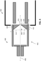
- FIG. 4 shows a simplified cross-sectional view of an example ion source 400 and a portion of an example ion transfer chamber 450.
- the ion source 400 and the ion chamber 450 can be used, for example, as the ion sources and ion transfer chambers shown in FIGS. 1 and 2 .
- the ion source 400 defines an approximately cylindrical chamber 402, and an extraction electrode 404 positioned at a far end of the chamber 402.
- the extraction electrode 404 has a generally annular cross section along an axial extension of the chamber 402 (e.g., along the ion beam axis or central axis 406), and defines an aperture 408. Further, the cross-sectional diameter of the aperture 408 monotonically decreases from the portion of the extraction electrode 404 closest of the center of the chamber 402 to the far end 410 of the chamber 402. Thus, the inner surface 412 of the extraction electrode 404 defines a frusto-conical shape (e.g., the aperture 408 is frusto-conical).
- the extraction electrode 404 can be altered to adjust the ion beam focusing and ion acceleration properties of the ion source 300.
- the axial length 422 of the extraction electrode 404 can be between 0.5 mm and 10 mm.
- the diameter 414 of the extraction electrode 404 can be between 0.5 mm and 5 mm.
- the conical angle 416 i.e., the angle between the central axis 406 and the inner surface 412 can be between 60 degrees and 150 degrees.
- the minimal annular thickness 418 can be between 0.5 mm and 2 mm.
- the maximum annular thickness 420 can be between 1 mm and 3 mm. In practice, other dimensions are also possible, depending on the implementation.
- the ion source 400 includes a single integral extraction electrode 404.
- FIG. 5 shows a simplified cross-sectional view of an ion source 500 and a portion of an ion chamber 550 that are outside the scope of the present invention. As before, the ion source 500 defines an approximately cylindrical chamber 502.
- the ion source 500 includes multiple extraction electrodes 504a-c.
- Each extraction electrode 504a-c in annular or disk-like in shape, each defining a respective aperture 506a-c.
- the apertures 506a-c are concentric, and collectively define an exit aperture 508.
- the cross-sectional diameter of the aperture 508 monotonically decreases from the extraction electrode 504a (i.e., the extraction electrode closest of the center of the chamber 502) to the extraction electrode 506c (i.e., the extraction electrode on the far end 510 of the chamber 502).
- the apertures 506-a-c define an approximately frusto-conical shape (e.g., a terraced frusto-conical shape).
- An electric potential can be applied to each extraction electrodes 504a-c. In some cases, the same electrical potential can be applied to each extraction electrode 504a-c. In some cases, different electric potentials can be applied to some or all of the extraction electrodes 504a-c. For example, in some cases, voltages applied to any electrode 504a-c can be in the range of -100 V to +100 V.
- each of the extraction electrode 504a-c can be altered to adjust the ion beam focusing and ion acceleration properties of the ion source 500.
- the axial length of each extraction electrode 504a-c can be between 0.5 mm to 3.0 mm.
- the diameter of each extraction electrode 504a-c can be between 1 mm and 10 mm.
- the inner diameter of each extraction electrode 504a-c can be between 0.5 mm and 5.0 mm.
- the minimal annular thickness e.g., the annular thickness of the center-most extraction electrode 504a
- the maximum annular thickness e.g., the annular thickness of the extraction electrode 504c closest to the end 510) can be between 0.5 mm and 5.0 mm. In practice, other dimensions are also possible, depending on the implementation.
- an ion source can include any number of extraction electrodes (e.g., one, two, three, four, five, or more). Similarly, the electric potential applied to each extraction electrode and the dimensions of each extraction electrode can differ to give the ion source different ion beam focusing and ion acceleration properties.
- an ion source can include a magnetic field generator configured to generate a magnetic field in a direction parallel to a direction of the electron beam and coincident with the electron beam. This can be useful, for example, as it can cause the electrons of the electron beam to travel in a helical direction about the direction of the electron beam, thereby lengthening the path of each electron within the ion chamber, and increasing the likelihood that each electron will interact with and ionize the analyte.
- FIG. 6 shows a simplified cross-sectional view of an ion source 600.
- the ion source 600 can be used, for example, as the ion sources shown in FIGS. 1 and 2 .
- the ion source 600 includes input ports 602a and 602b, a repeller 604, and an extraction electrode 606.
- the ion source 600 receives an analyte (e.g., eluted sample constituents from a GC column) through the input port 602a.
- the analyte is propelled into the ionization chamber 608 by the repeller 604.
- the ion source 300 also generates an electron beam 610 (e.g., by heating a wire filament with electric current running through it), and directs the electron beam 610 from the input port 602b into the ionization chamber 608.
- the ion source also includes two permanent magnets 612a and 612b positioned on opposite ends of the electron beam 610, and aligned in the direction parallel to the direction of the electron beam. This generates a magnetic field in the ion chamber 612 (represented by magnetic field vectors 614).
- FIG. 7 shows a simplified cross-sectional view of the example ion source 400 and the example ion transfer chamber 450 shown in FIG. 4 , and a portion of an example quadrupole mass filter 700.
- the ion source 400, the ion transfer chamber 450, and the quadrupole mass filter 700 can be used, for example, as the ion sources, ion transfer chambers, and quadrupole mass filters shown in FIGS. 1 and 2 .
- the ion chamber 450 defines an approximately cylindrical inner chamber 702.
- the ion chamber 450 also includes an ion guide 704 that extends along the length of the inner chamber 702. In the example shown in FIG.
- the ion guide 704 includes four parallel electrically conductive rods 702a-d arranged in a 2 x 2 configuration surrounding an ion guide axis 708, where each opposing rod pair (e.g., 702a and 702d, and 702b and 702c) is connected together electrically. Due to the cross-sectional view depicted in FIG. 7 , rods 702b and 702c are shown in cross-section, and rod 702d is not shown. An RF voltage is applied between each rod pair to generate a RF field in the inner chamber 702.
- each opposing rod pair e.g., 702a and 702d, and 702b and 702c
- Sample ions exiting the ion source 400 are passed into the inner chamber 702 of the ion transfer chamber 450, and are constrained by the RF field to oscillate about the ion guide axis 708 as they traverse the length of the inner chamber 702 and the ion guide 704.
- the ion guide 704 RF field induces a radial pseudo-potential well along the ion guide axis 708.
- the electrically conductive rods 702a-d are each equidistant from the ion guide axis 708, and are radially distributed about the ion guide axis 708 (e.g., positioned with 90° angular distance between them with respect to the ion guide axis 708).
- the distance between each conductive rod 702a-d and the ion guide axis 708 can vary.
- the radial distance 710 between ion guide axis 708 to a center of a conductive rod can be between 1 mm and 10 mm.
- the dimensions of the conductive rods 702a-d can also vary.
- the length 712 of each conductive rod 702a-d can be between 10 mm and 200 mm.
- the diameter 714 of each conductive rod 702a-d can be between 1 mm and 10 mm.
- the RF voltage applied to each opposing rod pair can also vary. For example, in some cases, a voltage between 10 V to beyond 1000 V RF can be used.
- the ion guide 704 can also include additional electrodes positioned either of the axial ends of the ion transfer chamber 450.
- the ion guide 704 includes four additional electrodes electrically conductive electrodes 716a-d arranged surrounding an ion guide axis 708, where each opposing rod pair (e.g., 716a and 716d, and 716b and 716c) is connected together electrically. Due to the cross-sectional view depicted in FIG. 7 , electrodes 716b and 716c are shown in cross-section, and electrode 716d is not shown.
- the each of the electrodes can be axially aligned with, and electrically connected to, a corresponding conductive rod.
- the electrode 716a can be axially aligned with and electrically connected to the rod 702a
- the electrode 716b can be axially aligned with and electrically connected to the rod 702b
- the electrode 716c can be axially aligned with and electrically connected to the rod 702c
- the electrode 716d can be axially aligned with and electrically connected to the rod 702d.
- This can be beneficial, for example, as it enables the ion guide 704 to generate a more consistent RF field within the inner chamber 702, thereby improving the focusing characteristics performance of the ion transfer chamber 450.
- ion transfer chamber 450 can also generate an axial electric field (i.e., an electric field extending along the direction of the path of travel of the sample ion beam along the ion guide axis 708) that further forces the sample ions axially through the ion transfer chamber 450.
- an axial electric field i.e., an electric field extending along the direction of the path of travel of the sample ion beam along the ion guide axis 708
- This can be useful, for example, in ensuring such that the collisions within the ion transfer chamber 450 do not significantly delay the transport of ions through the ion transfer chamber 450 and into the quadrupole mass filter.
- the ion transfer chamber 450 can also be pressurized with a gas.
- the ion transfer chamber 450 can include a gas manifold 718 (e.g., an input port or aperture) for receiving gas from a gas source (e.g., a gas tank), such that the inner chamber 702 is pressurized.
- the gas pressure can vary in the inner chamber 702.
- the gas pressure within the inner chamber 702 can be approximately 1 mTorr to 100 mTorr.
- gases can be used to pressurize the inner chamber 702, such as, nitrogen, argon, helium, etc.
- the sample ions can be focused into the entrance of the quadrupole mass filter 700 with improved beam characteristics.
- FIG. 8 shows a simplified cross-sectional view of an ion source 800, an ion transfer chamber 810, and a quadrupole mass filter 820 that are outside the scope of the present invention.
- the ion source 800, the ion transfer chamber 810, and the quadrupole mass filter 820 can be used, for example, as the ion sources, ion transfer chambers, and quadrupole mass filters shown in FIGS. 1 and 2 . Simulated paths of the ionized analyte are shown as paths 802. As shown in FIG. 8 , the ion source 800 receives an analyte (e.g., eluted sample constituents from a GC column) and ionizes the received particles. The ionized analyte is focused within the ion source 800, and accelerated into the ion transfer chamber 810.
- an analyte e.g., eluted sample constituents from a GC column
- the ion transfer chamber 810 further focuses the ionized analyte, and reduces the kinetic energy of the ionized analyte (due to the collisions for the gas pressurized within the ion transfer chamber 810).
- the ionized analyte is subsequently injected in the mass filter 820 for further processing.
- gas molecules can be directionally injected into the ion transfer chamber, such that a directional flow of gas is induced within the ion transfer chamber.
- This can be beneficial, for example, as it can reduce the sample ions' radial excursion and kinetic energies more rapidly than without such directed gas flow, as well as facilitate the continuous movement of ions along the axis as the ions experience collision cooling along the way, with or without the presence of an axial electric field.
- the gas molecules can be injected such that a flow of gas extends along an axis of extension of the ion transfer chamber, in the direction from the entrance of the ion transfer chamber to the exit of the ion transfer chamber.
- FIG. 9 shows a simplified cross-sectional view of the example ion source 900, an example ion transfer chamber 910, and an example quadrupole mass filter 920.
- the ion source 900, the ion transfer chamber 910, and the quadrupole mass filter 920 can be used, for example, as the ion sources, ion transfer chambers, and quadrupole mass filters shown in FIGS. 1 and 2 .
- gas molecules represented by dotted line 902 are directionally injected into the ion transfer chamber 910 (e.g., via gas ducts or conduits 904).
- the gas molecules flow across the ion transfer chamber 910 (e.g., in an axial direction along the axis of extension 906 of the ion transfer chamber 910), forming a directional gas jet. This gas jet propels the sample ions through the ion transfer chamber 910.
- the gas molecules can be directionally injected into the ion transfer chamber, such that the resulting gas jet imparts both an axial force and a radial force (e.g., orthogonal to the axial force) on the sample ions.
- the ion transfer chamber can include focusing or funneling structures 908 (e.g., baffles or flanges), that radially focus the gas molecules into a narrow stream. This can be useful, for example, to further compact the sample ions, and to further reduce the sample ions' radial excursion.
Landscapes
- Chemical & Material Sciences (AREA)
- Analytical Chemistry (AREA)
- Physics & Mathematics (AREA)
- Engineering & Computer Science (AREA)
- Plasma & Fusion (AREA)
- Other Investigation Or Analysis Of Materials By Electrical Means (AREA)
- Electron Tubes For Measurement (AREA)
Claims (15)
- System, umfassend:i) eine Elektronenionisationsquelle (104, 204, 400, 600), die dazu konfiguriert ist, im Betrieb des Systems aus Probenmolekülen einen Ionenstrahl zu erzeugen, der sich entlang einer Ionenstrahlachse erstreckt, wobei die Elektronenionisationsquelle aufweist:eine Elektronenquelle (316), die dazu konfiguriert ist, im Betrieb des Systems einen Elektronenstrom (126, 226, 312) zu erzeugen,eine Probeneintragsanordnung, die dazu konfiguriert ist, im Betrieb des Systems mindestens einen Analyten zu transportieren;eine Ionisationskammer (310) mit einer ersten Eingangsöffnung (302b), eine zweiten Eingangsöffnung (302a) und einer Ausgangsöffnung (132, 232, 308),wobei die erste Eingangsöffnung dazu konfiguriert ist, im Betrieb des Systems den Elektronenstrom (126, 226, 312) von der Elektronenquelle zu empfangen;wobei die zweite Eingangsöffnung dazu konfiguriert ist, im Betrieb des Systems den mindestens einen Analyten von der Probeneintragsanordnung zu empfangen, wobei durch Wechselwirkung zwischen dem mindestens einen Analyten und den Elektronen innerhalb eines Ionisationsbereichs der Ionisationskammer Analytionen erzeugt werden und wobei die Analytionen die Ionisationskammer durch die Ausgangsöffnung entlang einer Ionenstrahlachse verlassen;wobei die Ionisationskammer (310) mindestens zwei Kammerelektroden (304, 306, 404, 604, 606) umfasst, die so konfiguriert sind, dass im Betrieb des Systems jeweils unabhängig voneinander gesteuerte Spannungen daran angelegt werden,wobei die mindestens zwei Kammerelektroden eine einzelne integrale Extraktionselektrode (306, 404, 606) umfassen, die die Ausgangsöffnung definiert,wobei die Extraktionselektrode so konfiguriert ist, dass im Betrieb des Systems eine Extraktionselektrodenspannung daran angelegt wird,wobei die Extraktionselektrode eine stromaufwärtige Oberfläche umfasst, die zum Ionisationsbereich weist, wobei die stromaufwärtige Oberfläche eine kegelstumpfförmige Form mit einer kleineren Grundfläche und einer größeren Grundfläche definiert, wobei die kleinere Grundfläche proximal zur Ausgangsöffnung liegt oder damit zusammenfällt, wobei ein Querschnittsdurchmesser der stromaufwärtigen Oberfläche von einem Abschnitt der Extraktionselektrode, der einer Mitte der Ionisationskammer am nächsten liegt, zu einem anderen Ende (410) der Ionisationskammer gleichmäßig abnimmt,wobei im Betrieb des Systems elektrische Felder innerhalb der Ionisationskammer, die aus den an die Extraktionselektrode angelegten Spannungen resultieren, und mindestens eine andere der mindestens zwei Kammerelektroden (304, 604) wirken, um Analytionen aus dem Ionisationsbereich durch die Ausgangsöffnung zu fokussieren und zu beschleunigen;ii) eine Kollisionskühlkammer (106, 206a, 450, 910), die einen Gassammler (718) und einen elektrischen Feldgenerator (704) umfasst,wobei die Kühlkammer eine Eintrittsöffnung (132, 232) und eine Austrittsöffnung (140, 240) an jeweils entgegengesetzten Enden der Kühlkammer definiert, wobei die Eintrittsöffnung der Kühlkammer in axialer Ausrichtung zur Ionenstrahlachse verläuft,wobei die Kühlkammer dazu konfiguriert ist, im Betrieb des Systems:ein Hochfrequenzfeld innerhalb der Kühlkammer mithilfe des elektrischen Feldgenerators zu erzeugen undKollisionsgas durch den Gassammler zu empfangen, um die Kühlkammer unter Druck zu setzen; undiii) einen Massenanalysator (108, 208a, 700, 920).
- System nach Anspruch 1, wobei die Elektronenquelle (316) dazu konfiguriert ist, im Betrieb des Systems den Elektronenstrahl (610) in einer ersten Querrichtung innerhalb der Ionisationskammer (310) zu erzeugen, wobei die erste Querrichtung orthogonal zur Ionenstrahlachse verläuft und wobei die Ionisationskammer (310) einen Magnetfeldgenerator (612a, 612b) umfasst, der dazu konfiguriert ist, im Betrieb des Systems, ein Magnetfeld in einer Richtung parallel zu einer Richtung des Elektronenstrahls und mit dem Elektronenstrahl zusammenfallend zu erzeugen.
- System nach Anspruch 2, wobei der Magnetfeldgenerator mindestens zwei Dauermagnete (612a, 612b) umfasst.
- System nach Anspruch 3, wobei die mindestens zwei Dauermagnete in einer Richtung parallel zur Richtung des Elektronenstrahls ausgerichtet sind.
- System nach Anspruch 1, wobei der Massenanalysator (108, 208a, 700, 920) mindestens eines des Folgenden umfasst:ein Quadrupol-Massenfilter;eine Kombination aus zwei Quadrupol-Massenfiltern, die durch eine Kollisionskammer getrennt sind,eine Kombination aus einem Quadrupol-Massenfilter, einer Kollisionskammer und einem Flugzeit-Massenanalysator;einen Flugzeit-Massenanalysator;eine dreidimensionale Ionenfalle; odereine zweidimensionale Ionenfalle.
- System nach Anspruch 1, wobei der elektrische Feldgenerator ferner dazu konfiguriert ist, im Betrieb des Systems ein axiales elektrisches Feld zu erzeugen, das sich entlang mindestens eines Abschnitts einer Länge der Kühlkammer erstreckt.
- System nach Anspruch 1, wobei die Kühlkammer (106, 206a, 450, 810, 910) dazu konfiguriert ist, im Betrieb des Systems mit Kollisionsgas mit einem Druck zwischen 0,13 Pa und 13 Pa (1 mTorr und 100 mTorr) unter Druck gesetzt zu werden.
- System nach Anspruch 1, wobei die Kühlkammer (106, 206a, 450, 819, 910) dazu konfiguriert ist, im Betrieb des Systems:Ionen aus der Ionisationskammer (310) durch die Eintrittsöffnung (132, 232) zu empfangen;eine kinetische Energie mindestens einiger der empfangenen Ionen zu reduzieren; undmindestens einige der empfangenen Ionen durch die Kammeraustrittsöffnung (140, 240) aus der Kühlkammer auszustoßen.
- System nach Anspruch 8, wobei Reduzieren einer kinetischen Energie mindestens einiger der empfangenen Ionen Induzieren einer oder mehrerer Kollisionen zwischen den empfangenen Ionen und Molekülen des Kühlgases umfasst.
- System nach Anspruch 1, wobei der elektrische Feldgenerator (704) eine Vielzahl leitfähiger Stäbe (702a-d) umfasst, die sich entlang mindestens eines Abschnitts der Länge der Kühlkammer erstrecken, wobei die Stäbe innerhalb der Kühlkammer achsensymmetrisch angeordnet sind.
- System nach Anspruch 1, wobei die Kühlkammeraustrittsöffnung eine Vielzahl von Austrittsöffnungselektroden (716a-d) umfasst, die achsensymmetrisch um eine Kühlkammeraustrittsachse (708) angeordnet sind, wobei die Vielzahl von Austrittsöffnungselektroden so konfiguriert sind, dass im Betrieb des Systems HF- und DC-Offsetspannungen daran angelegt werden.
- System nach Anspruch 1, wobei der Massenanalysator (108, 208a, 700, 920) dazu konfiguriert ist, im Betrieb des Systems Ionen aus der Kühlkammer (106, 206a, 450, 910) für die Massenanalyse zu empfangen.
- System nach Anspruch 1, das ferner einen Gaschromatographen umfasst, wobei die Ionisationskammer dazu konfiguriert ist, im Betrieb des Systems einen Probenabfluss aus dem Gaschromatographen zu erhalten.
- System nach Anspruch 1, das ferner ein Steuermodul umfasst, das mit mindestens einem von der Elektronenionisationsquelle, der Kühlkammer, dem Massenanalysator, einem Massenanalysator-Detektionssystem, dem Gaschromatographen oder einer Transfervorrichtung kommunikativ gekoppelt ist,
wobei das Steuermodul dazu konfiguriert ist, im Betrieb des Systems einen Betrieb von mindestens einem von der Elektronenionisationsquelle, der Kühlkammer, dem Massenanalysator, dem Massenanalysator-Detektionssystem, dem Gaschromatographen oder der Transfervorrichtung zu regeln. - System nach Anspruch 14, wobei Regeln des Betriebs von mindestens einem von der Elektronenionisationsquelle, der Kühlkammer, dem Massenanalysator, dem Massenanalysator-Detektionssystem, dem Gaschromatographen oder der Transfervorrichtung umfasst:Regeln eines Transfers von Probenpartikeln aus dem Gaschromatographen in die Ionenquellenkammer; oderRegeln der Ionisation mindestens einiger der Probenpartikel durch die Ionenquellenkammer; oderRegeln eines elektrischen Potenzials jeder der einen oder mehreren Elektroden; oderRegeln der Erzeugung des HF-Feldes innerhalb der Kühlkammer durch den Elektrofeldgenerator; oderRegeln eines Transfers von Edelgas in die Kühlkammer durch den Gasverteiler.
Applications Claiming Priority (2)
| Application Number | Priority Date | Filing Date | Title |
|---|---|---|---|
| US201762480738P | 2017-04-03 | 2017-04-03 | |
| PCT/US2018/025221 WO2018187162A1 (en) | 2017-04-03 | 2018-03-29 | Ion transfer from electron ionization sources |
Publications (4)
| Publication Number | Publication Date |
|---|---|
| EP3607576A1 EP3607576A1 (de) | 2020-02-12 |
| EP3607576A4 EP3607576A4 (de) | 2020-12-30 |
| EP3607576B1 true EP3607576B1 (de) | 2023-08-23 |
| EP3607576B8 EP3607576B8 (de) | 2023-10-04 |
Family
ID=63669774
Family Applications (1)
| Application Number | Title | Priority Date | Filing Date |
|---|---|---|---|
| EP18780424.0A Active EP3607576B8 (de) | 2017-04-03 | 2018-03-29 | Ionentransfer von elektronenionisationsquellen |
Country Status (5)
| Country | Link |
|---|---|
| US (1) | US10692712B2 (de) |
| EP (1) | EP3607576B8 (de) |
| JP (1) | JP7210536B2 (de) |
| CN (1) | CN110637352B (de) |
| WO (1) | WO2018187162A1 (de) |
Families Citing this family (6)
| Publication number | Priority date | Publication date | Assignee | Title |
|---|---|---|---|---|
| CN109716484B (zh) * | 2016-09-21 | 2021-02-09 | 株式会社岛津制作所 | 质谱分析装置 |
| WO2020166060A1 (ja) * | 2019-02-15 | 2020-08-20 | 株式会社島津製作所 | 質量分析装置および質量分析方法 |
| CN111706481B (zh) * | 2020-06-19 | 2021-06-22 | 哈尔滨工业大学 | 一种基于电离与加速过程解耦的离子风推力装置 |
| US11092569B1 (en) * | 2020-07-05 | 2021-08-17 | Cannabix Technologies Inc. | Apparatus and methods for detection of molecules |
| CN112863979B (zh) * | 2021-01-14 | 2022-02-08 | 西安交通大学 | 一种微纳尺度离子束外束引出装置 |
| CN112992646B (zh) * | 2021-02-08 | 2023-03-28 | 清华大学深圳国际研究生院 | 一种小型离子阱质谱仪的射频电压施加方法 |
Family Cites Families (22)
| Publication number | Priority date | Publication date | Assignee | Title |
|---|---|---|---|---|
| US6800846B2 (en) * | 2002-05-30 | 2004-10-05 | Micromass Uk Limited | Mass spectrometer |
| US6919562B1 (en) * | 2002-05-31 | 2005-07-19 | Analytica Of Branford, Inc. | Fragmentation methods for mass spectrometry |
| JP2006521006A (ja) * | 2003-03-03 | 2006-09-14 | ブリガム・ヤング・ユニバーシティ | 直交加速飛行時間型質量分析のための新規な電子イオン化源 |
| US7291845B2 (en) * | 2005-04-26 | 2007-11-06 | Varian, Inc. | Method for controlling space charge-driven ion instabilities in electron impact ion sources |
| US7166836B1 (en) * | 2005-09-07 | 2007-01-23 | Agilent Technologies, Inc. | Ion beam focusing device |
| EP2126957A4 (de) * | 2007-01-19 | 2012-05-30 | Mds Analytical Tech Bu Mds Inc | Vorrichtung und verfahren zum kühlen von ionen |
| US7595487B2 (en) * | 2007-08-24 | 2009-09-29 | Georgia Tech Research Corporation | Confining/focusing vortex flow transmission structure, mass spectrometry systems, and methods of transmitting particles, droplets, and ions |
| US7838826B1 (en) * | 2008-08-07 | 2010-11-23 | Bruker Daltonics, Inc. | Apparatus and method for parallel flow ion mobility spectrometry combined with mass spectrometry |
| JP5234019B2 (ja) | 2010-01-29 | 2013-07-10 | 株式会社島津製作所 | 質量分析装置 |
| CN102169791B (zh) * | 2010-02-05 | 2015-11-25 | 岛津分析技术研发(上海)有限公司 | 一种串级质谱分析装置及质谱分析方法 |
| US8389929B2 (en) * | 2010-03-02 | 2013-03-05 | Thermo Finnigan Llc | Quadrupole mass spectrometer with enhanced sensitivity and mass resolving power |
| DE102010022184B4 (de) * | 2010-05-21 | 2013-04-04 | Bruker Daltonik Gmbh | Mischfrequenz-Stabsystem als Ionenreaktor |
| US8299443B1 (en) | 2011-04-14 | 2012-10-30 | Battelle Memorial Institute | Microchip and wedge ion funnels and planar ion beam analyzers using same |
| US9831078B2 (en) * | 2012-01-27 | 2017-11-28 | Agilent Technologies, Inc. | Ion source for mass spectrometers |
| CN103367093B (zh) * | 2012-03-30 | 2016-12-21 | 岛津分析技术研发(上海)有限公司 | 线型离子束缚装置及其阵列结构 |
| GB201208733D0 (en) * | 2012-05-18 | 2012-07-04 | Micromass Ltd | Excitation of reagent molecules within a rf confined ion guide or ion trap to perform ion molecule, ion radical or ion-ion interaction experiments |
| JP6045315B2 (ja) * | 2012-11-20 | 2016-12-14 | 日本電子株式会社 | 質量分析装置及び質量分析装置の調整方法 |
| JP6054715B2 (ja) * | 2012-11-20 | 2016-12-27 | 日本電子株式会社 | 質量分析装置及び質量分析装置の制御方法 |
| US9613788B2 (en) * | 2014-06-13 | 2017-04-04 | Perkinelmer Health Sciences, Inc. | RF ion guide with axial fields |
| JP2016009562A (ja) * | 2014-06-24 | 2016-01-18 | 株式会社島津製作所 | イオン輸送装置及び質量分析装置 |
| US20160181080A1 (en) * | 2014-12-23 | 2016-06-23 | Agilent Technologies, Inc. | Multipole ion guides utilizing segmented and helical electrodes, and related systems and methods |
| CN104599933B (zh) * | 2015-01-08 | 2017-12-15 | 聚光科技(杭州)股份有限公司 | 一种电子电离源 |
-
2018
- 2018-03-29 CN CN201880032812.0A patent/CN110637352B/zh active Active
- 2018-03-29 US US15/940,431 patent/US10692712B2/en active Active
- 2018-03-29 JP JP2020502522A patent/JP7210536B2/ja active Active
- 2018-03-29 WO PCT/US2018/025221 patent/WO2018187162A1/en unknown
- 2018-03-29 EP EP18780424.0A patent/EP3607576B8/de active Active
Also Published As
| Publication number | Publication date |
|---|---|
| WO2018187162A1 (en) | 2018-10-11 |
| CN110637352B (zh) | 2022-10-04 |
| EP3607576B8 (de) | 2023-10-04 |
| JP2020513154A (ja) | 2020-04-30 |
| EP3607576A1 (de) | 2020-02-12 |
| EP3607576A4 (de) | 2020-12-30 |
| CN110637352A (zh) | 2019-12-31 |
| US20180286657A1 (en) | 2018-10-04 |
| JP7210536B2 (ja) | 2023-01-23 |
| US10692712B2 (en) | 2020-06-23 |
Similar Documents
| Publication | Publication Date | Title |
|---|---|---|
| EP3607576B1 (de) | Ionentransfer von elektronenionisationsquellen | |
| US8324565B2 (en) | Ion funnel for mass spectrometry | |
| EP1116258B1 (de) | Ionenoptik vorrichtung für massenspektrometrie | |
| US20190013193A1 (en) | IRMS Sample Introduction System and Method | |
| US9455132B2 (en) | Ion mobility spectrometry-mass spectrometry (IMS-MS) with improved ion transmission and IMS resolution | |
| EP2819144B1 (de) | Ionenquelle mit axialem magnetischem Feld und zugehörige Ionisierungsverfahren | |
| US7166836B1 (en) | Ion beam focusing device | |
| US20080087814A1 (en) | Multi path tof mass analysis within single flight tube and mirror | |
| JP2016115674A (ja) | ソフト電子イオン化のためのイオン源ならびに関連するシステムおよび方法 | |
| EP0210182B1 (de) | Sekundärionenauffang- und transportvorrichtung für ionenmikroproben | |
| CN110573865B (zh) | 无机和有机质谱系统及其使用方法 | |
| US11276544B2 (en) | Dynamic electron impact ion source | |
| US5633496A (en) | Mass spectrometry apparatus | |
| EP4089713A1 (de) | Hybride massenspektrometrievorrichtung | |
| US10658167B2 (en) | Off-axis ionization devices and systems using them | |
| GB2444358A (en) | Time division multiplexing mass spectrometry with beam converging capillary | |
| JP2000100375A (ja) | 質量分析計及びその静電レンズ | |
| CA3170110A1 (en) | Ion interfaces and systems and methods using them | |
| WO2021021459A1 (en) | Axially progressive lens for transporting charged particles |
Legal Events
| Date | Code | Title | Description |
|---|---|---|---|
| STAA | Information on the status of an ep patent application or granted ep patent |
Free format text: STATUS: THE INTERNATIONAL PUBLICATION HAS BEEN MADE |
|
| PUAI | Public reference made under article 153(3) epc to a published international application that has entered the european phase |
Free format text: ORIGINAL CODE: 0009012 |
|
| STAA | Information on the status of an ep patent application or granted ep patent |
Free format text: STATUS: REQUEST FOR EXAMINATION WAS MADE |
|
| 17P | Request for examination filed |
Effective date: 20191104 |
|
| AK | Designated contracting states |
Kind code of ref document: A1 Designated state(s): AL AT BE BG CH CY CZ DE DK EE ES FI FR GB GR HR HU IE IS IT LI LT LU LV MC MK MT NL NO PL PT RO RS SE SI SK SM TR |
|
| AX | Request for extension of the european patent |
Extension state: BA ME |
|
| DAV | Request for validation of the european patent (deleted) | ||
| DAX | Request for extension of the european patent (deleted) | ||
| A4 | Supplementary search report drawn up and despatched |
Effective date: 20201201 |
|
| RIC1 | Information provided on ipc code assigned before grant |
Ipc: H01J 49/06 20060101AFI20201126BHEP Ipc: H01J 49/14 20060101ALI20201126BHEP |
|
| GRAP | Despatch of communication of intention to grant a patent |
Free format text: ORIGINAL CODE: EPIDOSNIGR1 |
|
| STAA | Information on the status of an ep patent application or granted ep patent |
Free format text: STATUS: GRANT OF PATENT IS INTENDED |
|
| INTG | Intention to grant announced |
Effective date: 20230303 |
|
| GRAS | Grant fee paid |
Free format text: ORIGINAL CODE: EPIDOSNIGR3 |
|
| P01 | Opt-out of the competence of the unified patent court (upc) registered |
Effective date: 20230601 |
|
| GRAA | (expected) grant |
Free format text: ORIGINAL CODE: 0009210 |
|
| STAA | Information on the status of an ep patent application or granted ep patent |
Free format text: STATUS: THE PATENT HAS BEEN GRANTED |
|
| REG | Reference to a national code |
Ref country code: DE Ref legal event code: R081 Ref document number: 602018055992 Country of ref document: DE Owner name: PERKINELMER U.S. LLC, SHELTON, US Free format text: FORMER OWNER: PERKINELMER HEALTH SCIENCES, INC., WALTHAM, MA, US |
|
| AK | Designated contracting states |
Kind code of ref document: B1 Designated state(s): AL AT BE BG CH CY CZ DE DK EE ES FI FR GB GR HR HU IE IS IT LI LT LU LV MC MK MT NL NO PL PT RO RS SE SI SK SM TR |
|
| REG | Reference to a national code |
Ref country code: GB Ref legal event code: FG4D |
|
| REG | Reference to a national code |
Ref country code: CH Ref legal event code: EP |
|
| RAP2 | Party data changed (patent owner data changed or rights of a patent transferred) |
Owner name: PERKINELMER U.S. LLC |
|
| REG | Reference to a national code |
Ref country code: DE Ref legal event code: R096 Ref document number: 602018055992 Country of ref document: DE |
|
| REG | Reference to a national code |
Ref country code: IE Ref legal event code: FG4D |
|
| REG | Reference to a national code |
Ref country code: CH Ref legal event code: PK Free format text: BERICHTIGUNG B8 |
|
| REG | Reference to a national code |
Ref country code: LT Ref legal event code: MG9D |
|
| REG | Reference to a national code |
Ref country code: NL Ref legal event code: MP Effective date: 20230823 |
|
| REG | Reference to a national code |
Ref country code: AT Ref legal event code: MK05 Ref document number: 1603603 Country of ref document: AT Kind code of ref document: T Effective date: 20230823 |
|
| PG25 | Lapsed in a contracting state [announced via postgrant information from national office to epo] |
Ref country code: GR Free format text: LAPSE BECAUSE OF FAILURE TO SUBMIT A TRANSLATION OF THE DESCRIPTION OR TO PAY THE FEE WITHIN THE PRESCRIBED TIME-LIMIT Effective date: 20231124 |
|
| PG25 | Lapsed in a contracting state [announced via postgrant information from national office to epo] |
Ref country code: IS Free format text: LAPSE BECAUSE OF FAILURE TO SUBMIT A TRANSLATION OF THE DESCRIPTION OR TO PAY THE FEE WITHIN THE PRESCRIBED TIME-LIMIT Effective date: 20231223 |
|
| PG25 | Lapsed in a contracting state [announced via postgrant information from national office to epo] |
Ref country code: SE Free format text: LAPSE BECAUSE OF FAILURE TO SUBMIT A TRANSLATION OF THE DESCRIPTION OR TO PAY THE FEE WITHIN THE PRESCRIBED TIME-LIMIT Effective date: 20230823 Ref country code: RS Free format text: LAPSE BECAUSE OF FAILURE TO SUBMIT A TRANSLATION OF THE DESCRIPTION OR TO PAY THE FEE WITHIN THE PRESCRIBED TIME-LIMIT Effective date: 20230823 Ref country code: PT Free format text: LAPSE BECAUSE OF FAILURE TO SUBMIT A TRANSLATION OF THE DESCRIPTION OR TO PAY THE FEE WITHIN THE PRESCRIBED TIME-LIMIT Effective date: 20231226 Ref country code: NO Free format text: LAPSE BECAUSE OF FAILURE TO SUBMIT A TRANSLATION OF THE DESCRIPTION OR TO PAY THE FEE WITHIN THE PRESCRIBED TIME-LIMIT Effective date: 20231123 Ref country code: NL Free format text: LAPSE BECAUSE OF FAILURE TO SUBMIT A TRANSLATION OF THE DESCRIPTION OR TO PAY THE FEE WITHIN THE PRESCRIBED TIME-LIMIT Effective date: 20230823 Ref country code: LV Free format text: LAPSE BECAUSE OF FAILURE TO SUBMIT A TRANSLATION OF THE DESCRIPTION OR TO PAY THE FEE WITHIN THE PRESCRIBED TIME-LIMIT Effective date: 20230823 Ref country code: LT Free format text: LAPSE BECAUSE OF FAILURE TO SUBMIT A TRANSLATION OF THE DESCRIPTION OR TO PAY THE FEE WITHIN THE PRESCRIBED TIME-LIMIT Effective date: 20230823 Ref country code: IS Free format text: LAPSE BECAUSE OF FAILURE TO SUBMIT A TRANSLATION OF THE DESCRIPTION OR TO PAY THE FEE WITHIN THE PRESCRIBED TIME-LIMIT Effective date: 20231223 Ref country code: HR Free format text: LAPSE BECAUSE OF FAILURE TO SUBMIT A TRANSLATION OF THE DESCRIPTION OR TO PAY THE FEE WITHIN THE PRESCRIBED TIME-LIMIT Effective date: 20230823 Ref country code: GR Free format text: LAPSE BECAUSE OF FAILURE TO SUBMIT A TRANSLATION OF THE DESCRIPTION OR TO PAY THE FEE WITHIN THE PRESCRIBED TIME-LIMIT Effective date: 20231124 Ref country code: FI Free format text: LAPSE BECAUSE OF FAILURE TO SUBMIT A TRANSLATION OF THE DESCRIPTION OR TO PAY THE FEE WITHIN THE PRESCRIBED TIME-LIMIT Effective date: 20230823 Ref country code: AT Free format text: LAPSE BECAUSE OF FAILURE TO SUBMIT A TRANSLATION OF THE DESCRIPTION OR TO PAY THE FEE WITHIN THE PRESCRIBED TIME-LIMIT Effective date: 20230823 |
|
| PG25 | Lapsed in a contracting state [announced via postgrant information from national office to epo] |
Ref country code: PL Free format text: LAPSE BECAUSE OF FAILURE TO SUBMIT A TRANSLATION OF THE DESCRIPTION OR TO PAY THE FEE WITHIN THE PRESCRIBED TIME-LIMIT Effective date: 20230823 |
|
| PG25 | Lapsed in a contracting state [announced via postgrant information from national office to epo] |
Ref country code: ES Free format text: LAPSE BECAUSE OF FAILURE TO SUBMIT A TRANSLATION OF THE DESCRIPTION OR TO PAY THE FEE WITHIN THE PRESCRIBED TIME-LIMIT Effective date: 20230823 |
|
| PG25 | Lapsed in a contracting state [announced via postgrant information from national office to epo] |
Ref country code: SM Free format text: LAPSE BECAUSE OF FAILURE TO SUBMIT A TRANSLATION OF THE DESCRIPTION OR TO PAY THE FEE WITHIN THE PRESCRIBED TIME-LIMIT Effective date: 20230823 Ref country code: RO Free format text: LAPSE BECAUSE OF FAILURE TO SUBMIT A TRANSLATION OF THE DESCRIPTION OR TO PAY THE FEE WITHIN THE PRESCRIBED TIME-LIMIT Effective date: 20230823 Ref country code: ES Free format text: LAPSE BECAUSE OF FAILURE TO SUBMIT A TRANSLATION OF THE DESCRIPTION OR TO PAY THE FEE WITHIN THE PRESCRIBED TIME-LIMIT Effective date: 20230823 Ref country code: EE Free format text: LAPSE BECAUSE OF FAILURE TO SUBMIT A TRANSLATION OF THE DESCRIPTION OR TO PAY THE FEE WITHIN THE PRESCRIBED TIME-LIMIT Effective date: 20230823 Ref country code: DK Free format text: LAPSE BECAUSE OF FAILURE TO SUBMIT A TRANSLATION OF THE DESCRIPTION OR TO PAY THE FEE WITHIN THE PRESCRIBED TIME-LIMIT Effective date: 20230823 Ref country code: CZ Free format text: LAPSE BECAUSE OF FAILURE TO SUBMIT A TRANSLATION OF THE DESCRIPTION OR TO PAY THE FEE WITHIN THE PRESCRIBED TIME-LIMIT Effective date: 20230823 Ref country code: SK Free format text: LAPSE BECAUSE OF FAILURE TO SUBMIT A TRANSLATION OF THE DESCRIPTION OR TO PAY THE FEE WITHIN THE PRESCRIBED TIME-LIMIT Effective date: 20230823 |