EP3607573B1 - Fernbedienung mit konfigurierbaren tasten - Google Patents
Fernbedienung mit konfigurierbaren tasten Download PDFInfo
- Publication number
- EP3607573B1 EP3607573B1 EP18781478.5A EP18781478A EP3607573B1 EP 3607573 B1 EP3607573 B1 EP 3607573B1 EP 18781478 A EP18781478 A EP 18781478A EP 3607573 B1 EP3607573 B1 EP 3607573B1
- Authority
- EP
- European Patent Office
- Prior art keywords
- button
- interchangeable
- remote control
- receptacle
- label
- Prior art date
- Legal status (The legal status is an assumption and is not a legal conclusion. Google has not performed a legal analysis and makes no representation as to the accuracy of the status listed.)
- Active
Links
Images




Classifications
-
- H—ELECTRICITY
- H01—ELECTRIC ELEMENTS
- H01H—ELECTRIC SWITCHES; RELAYS; SELECTORS; EMERGENCY PROTECTIVE DEVICES
- H01H13/00—Switches having rectilinearly-movable operating part or parts adapted for pushing or pulling in one direction only, e.g. push-button switch
- H01H13/70—Switches having rectilinearly-movable operating part or parts adapted for pushing or pulling in one direction only, e.g. push-button switch having a plurality of operating members associated with different sets of contacts, e.g. keyboard
- H01H13/83—Switches having rectilinearly-movable operating part or parts adapted for pushing or pulling in one direction only, e.g. push-button switch having a plurality of operating members associated with different sets of contacts, e.g. keyboard characterised by legends, e.g. Braille, liquid crystal displays, light emitting or optical elements
-
- G—PHYSICS
- G06—COMPUTING OR CALCULATING; COUNTING
- G06K—GRAPHICAL DATA READING; PRESENTATION OF DATA; RECORD CARRIERS; HANDLING RECORD CARRIERS
- G06K19/00—Record carriers for use with machines and with at least a part designed to carry digital markings
- G06K19/06—Record carriers for use with machines and with at least a part designed to carry digital markings characterised by the kind of the digital marking, e.g. shape, nature, code
- G06K19/067—Record carriers with conductive marks, printed circuits or semiconductor circuit elements, e.g. credit or identity cards also with resonating or responding marks without active components
- G06K19/07—Record carriers with conductive marks, printed circuits or semiconductor circuit elements, e.g. credit or identity cards also with resonating or responding marks without active components with integrated circuit chips
- G06K19/0701—Record carriers with conductive marks, printed circuits or semiconductor circuit elements, e.g. credit or identity cards also with resonating or responding marks without active components with integrated circuit chips at least one of the integrated circuit chips comprising an arrangement for power management
- G06K19/0702—Record carriers with conductive marks, printed circuits or semiconductor circuit elements, e.g. credit or identity cards also with resonating or responding marks without active components with integrated circuit chips at least one of the integrated circuit chips comprising an arrangement for power management the arrangement including a battery
-
- G—PHYSICS
- G06—COMPUTING OR CALCULATING; COUNTING
- G06K—GRAPHICAL DATA READING; PRESENTATION OF DATA; RECORD CARRIERS; HANDLING RECORD CARRIERS
- G06K19/00—Record carriers for use with machines and with at least a part designed to carry digital markings
- G06K19/06—Record carriers for use with machines and with at least a part designed to carry digital markings characterised by the kind of the digital marking, e.g. shape, nature, code
- G06K19/067—Record carriers with conductive marks, printed circuits or semiconductor circuit elements, e.g. credit or identity cards also with resonating or responding marks without active components
- G06K19/07—Record carriers with conductive marks, printed circuits or semiconductor circuit elements, e.g. credit or identity cards also with resonating or responding marks without active components with integrated circuit chips
- G06K19/0719—Record carriers with conductive marks, printed circuits or semiconductor circuit elements, e.g. credit or identity cards also with resonating or responding marks without active components with integrated circuit chips at least one of the integrated circuit chips comprising an arrangement for application selection, e.g. an acceleration sensor or a set of radio buttons
-
- G—PHYSICS
- G06—COMPUTING OR CALCULATING; COUNTING
- G06K—GRAPHICAL DATA READING; PRESENTATION OF DATA; RECORD CARRIERS; HANDLING RECORD CARRIERS
- G06K19/00—Record carriers for use with machines and with at least a part designed to carry digital markings
- G06K19/06—Record carriers for use with machines and with at least a part designed to carry digital markings characterised by the kind of the digital marking, e.g. shape, nature, code
- G06K19/067—Record carriers with conductive marks, printed circuits or semiconductor circuit elements, e.g. credit or identity cards also with resonating or responding marks without active components
- G06K19/07—Record carriers with conductive marks, printed circuits or semiconductor circuit elements, e.g. credit or identity cards also with resonating or responding marks without active components with integrated circuit chips
- G06K19/077—Constructional details, e.g. mounting of circuits in the carrier
- G06K19/0772—Physical layout of the record carrier
- G06K19/07732—Physical layout of the record carrier the record carrier having a housing or construction similar to well-known portable memory devices, such as SD cards, USB or memory sticks
-
- G—PHYSICS
- G08—SIGNALLING
- G08C—TRANSMISSION SYSTEMS FOR MEASURED VALUES, CONTROL OR SIMILAR SIGNALS
- G08C17/00—Arrangements for transmitting signals characterised by the use of a wireless electrical link
- G08C17/02—Arrangements for transmitting signals characterised by the use of a wireless electrical link using a radio link
-
- H—ELECTRICITY
- H05—ELECTRIC TECHNIQUES NOT OTHERWISE PROVIDED FOR
- H05K—PRINTED CIRCUITS; CASINGS OR CONSTRUCTIONAL DETAILS OF ELECTRIC APPARATUS; MANUFACTURE OF ASSEMBLAGES OF ELECTRICAL COMPONENTS
- H05K5/00—Casings, cabinets or drawers for electric apparatus
- H05K5/0017—Casings, cabinets or drawers for electric apparatus with operator interface units
-
- G—PHYSICS
- G08—SIGNALLING
- G08C—TRANSMISSION SYSTEMS FOR MEASURED VALUES, CONTROL OR SIMILAR SIGNALS
- G08C2201/00—Transmission systems of control signals via wireless link
- G08C2201/30—User interface
-
- H—ELECTRICITY
- H01—ELECTRIC ELEMENTS
- H01H—ELECTRIC SWITCHES; RELAYS; SELECTORS; EMERGENCY PROTECTIVE DEVICES
- H01H2219/00—Legends
- H01H2219/002—Legends replaceable; adaptable
-
- H—ELECTRICITY
- H01—ELECTRIC ELEMENTS
- H01H—ELECTRIC SWITCHES; RELAYS; SELECTORS; EMERGENCY PROTECTIVE DEVICES
- H01H2219/00—Legends
- H01H2219/028—Printed information
-
- H—ELECTRICITY
- H01—ELECTRIC ELEMENTS
- H01H—ELECTRIC SWITCHES; RELAYS; SELECTORS; EMERGENCY PROTECTIVE DEVICES
- H01H2221/00—Actuators
- H01H2221/032—Actuators adjustable
- H01H2221/034—Coded keys
-
- H—ELECTRICITY
- H01—ELECTRIC ELEMENTS
- H01H—ELECTRIC SWITCHES; RELAYS; SELECTORS; EMERGENCY PROTECTIVE DEVICES
- H01H2239/00—Miscellaneous
- H01H2239/056—Keyboard or overlay identification features
-
- H—ELECTRICITY
- H01—ELECTRIC ELEMENTS
- H01H—ELECTRIC SWITCHES; RELAYS; SELECTORS; EMERGENCY PROTECTIVE DEVICES
- H01H2300/00—Orthogonal indexing scheme relating to electric switches, relays, selectors or emergency protective devices covered by H01H
- H01H2300/03—Application domotique, e.g. for house automation, bus connected switches, sensors, loads or intelligent wiring
- H01H2300/032—Application domotique, e.g. for house automation, bus connected switches, sensors, loads or intelligent wiring using RFID technology in switching devices
-
- Y—GENERAL TAGGING OF NEW TECHNOLOGICAL DEVELOPMENTS; GENERAL TAGGING OF CROSS-SECTIONAL TECHNOLOGIES SPANNING OVER SEVERAL SECTIONS OF THE IPC; TECHNICAL SUBJECTS COVERED BY FORMER USPC CROSS-REFERENCE ART COLLECTIONS [XRACs] AND DIGESTS
- Y02—TECHNOLOGIES OR APPLICATIONS FOR MITIGATION OR ADAPTATION AGAINST CLIMATE CHANGE
- Y02B—CLIMATE CHANGE MITIGATION TECHNOLOGIES RELATED TO BUILDINGS, e.g. HOUSING, HOUSE APPLIANCES OR RELATED END-USER APPLICATIONS
- Y02B90/00—Enabling technologies or technologies with a potential or indirect contribution to GHG emissions mitigation
- Y02B90/20—Smart grids as enabling technology in buildings sector
-
- Y—GENERAL TAGGING OF NEW TECHNOLOGICAL DEVELOPMENTS; GENERAL TAGGING OF CROSS-SECTIONAL TECHNOLOGIES SPANNING OVER SEVERAL SECTIONS OF THE IPC; TECHNICAL SUBJECTS COVERED BY FORMER USPC CROSS-REFERENCE ART COLLECTIONS [XRACs] AND DIGESTS
- Y04—INFORMATION OR COMMUNICATION TECHNOLOGIES HAVING AN IMPACT ON OTHER TECHNOLOGY AREAS
- Y04S—SYSTEMS INTEGRATING TECHNOLOGIES RELATED TO POWER NETWORK OPERATION, COMMUNICATION OR INFORMATION TECHNOLOGIES FOR IMPROVING THE ELECTRICAL POWER GENERATION, TRANSMISSION, DISTRIBUTION, MANAGEMENT OR USAGE, i.e. SMART GRIDS
- Y04S20/00—Management or operation of end-user stationary applications or the last stages of power distribution; Controlling, monitoring or operating thereof
- Y04S20/14—Protecting elements, switches, relays or circuit breakers
Definitions
- This disclosure is generally related to remote control devices, or any other devices, that feature configurable and interchangeable pre-labeled buttons. These remote control devices may be used to control media systems, for example.
- US2012/280800A1 discloses a man/machine dialogue system.
- US2005/269196A1 discloses a controller having a reduced control key set and a method for operating the same in a learning, macro, or cloning mode.
- WO2010/088607A1 discloses a touch music player.
- US2016/266658A1 discloses a keyboard and a method of controlling the same.
- a remote control for an entertainment system as specified in claim 1.
- the remote control may optionally be as specified in any one of claims 2 to 15.
- FIG. 1 shows an exemplary multimedia environment 100.
- multimedia environment 100 is a streaming media environment.
- Remote control 140 can be any component, part, apparatus or method for controlling media device 130 and/or display device 120, such as a remote control, a smartphone, a touchpad, a computer, a keyboard or integrated control buttons on a unit, to name just a few examples.
- platform 210 includes at least four receptacles 240 that are configured to receive a receptacle interface side of an interchangeable button 250.
- platform 210 has 16 receptacles 240 organized into 4 rows.
- platform 210 is not limited to this example embodiment, and may have any number of receptacles 240 arranged in any pattern.
- row 230 shows four interchangeable buttons 250 inserted into receptacles 240.
- additional interchangeable buttons 250 may be inserted by users into any available (i.e., empty) receptacles 240, like in row 220.
- interchangeable buttons 250 may be repositioned to any of the available receptacles according to user's preference.
- any row of receptacles 240 may receive an interchangeable panel of 4 buttons 250 that is inserted into a row with available receptacles, such as receptacle row 220.
- the buttons of the panel are fixed on the interchangeable panel in a predetermined order and are not interchangeable.
- the panels themselves are interchangeable and may be repositioned across different rows of available receptacles.
- each interchangeable panel may have two or more fixed buttons; the number of buttons in a panel can be the same as or less than the number of receptacles in a row.
- an interchangeable button 250 is inserted into a receptacle 240, the interchangeable button 250 becomes mechanically integrated with platform 210 and an electrical communication is established between them.
- FIG. 3 is a perspective view of an exemplary interchangeable button 300, which is similar to interchangeable button 250 of apparatus 200.
- interchangeable button 300 has receptacle interface electrodes 310 on a first side 320, and a second side 330 that has a user-perceivable label 350.
- the user-perceivable label 350 can be, for example, a label with the logo of an online commercial streaming service or vendor, or an image denoting a function or command (such as fast forward, mute, play, etc.).
- FIG. 4 is a top-down view of an interchangeable button 300 showing second side 330 with an exemplary user-perceivable label 350.
- FIG 5 is a cross-sectional view of an exemplary interchangeable button 300 taken along cut 340 of FIG. 3 , according to some embodiments.
- element 500 Embedded in the button is element 500 which is configured to functionally correspond to the unique user-perceivable label 350 on second side 330, so that there is an established unique correlation between the label on the button and element 500.
- element 500 is an RFID chip that operates as a read-only RFID tag having a factory-assigned serial number that functionally corresponds to the unique user-perceivable label 350.
- the RFID tag may be either passive, active or battery-assisted passive.
- element 500 may be one or more electrical elements that include passive elements, such as resistors, capacitors, inductors, and diodes; or active elements, such as transistors, silicon-controlled rectifiers (SCRs) and the like; or a combinations of thereof.
- passive elements such as resistors, capacitors, inductors, and diodes
- active elements such as transistors, silicon-controlled rectifiers (SCRs) and the like; or a combinations of thereof.
- FIG. 6 is an internal block diagram of an exemplary receptacle 600.
- Receptacle 600 may be an example embodiment of receptacle 240 of platform 210 of FIG. 2 .
- Receptacle 600 has an opening 650 where button 300 may be inserted by the user. Opening 650 features receptacle interface electrodes 610 which are configured to electrically connect to receptacle interface electrodes 310 of interchangeable button 300 of FIG. 3 .
- one of the interface electrodes 610 is connected to a power source 620 (which may be a battery, for example), and the other to a sensing circuitry 630.
- Sensing circuitry 630 is further connected to an electrical ground 640.
- each receptacle 600 is configured to provide power through power source 620 to element 500 when an interchangeable button is inserted to opening 650.
- element 500 is an RFID chip (tag), and sensing circuitry 630 may be, by example, an RFID reader configured to transmit an encoded radio signal to interrogate the RFID tag. The RFID tag receives the message, and then responds with its factory-assigned serial number which corresponds to and identifies its unique user-perceivable label 350.
- element 500 is one or more electrical elements as described above, and sensing circuitry 630 is configured to recognize a defining property of element 500. For example, if element 500 is a resistor, then sensing circuitry 630 may be configured to read the resistance of the resistor element by determining the voltage or current at sensing circuitry 630 (given the current/voltage output by the power source 620).
- platform 210 is configured to provide, for each receptacle 600 that has received an interchangeable button 300 in opening 650, an electrical signal based at least in part on a characteristic property of element 500. Based on this electrical signal, the remote control is able to identify the function of the button and then take corresponding action (as discussed below).
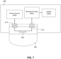
- FIG. 7 shows an exemplary interchangeable button 300 (shown in outline for illustrative purposes) inserted into opening 650 of an exemplary receptacle 600.
- Receptacle interface electrodes 610 of receptacle 600 and electrodes 310 of button 300 are aligned but not in contact. Electrical contact is established when button 300 is pressed by the user. At that point, power is provided to element 500 and sensing circuitry 630 reads/identifies element 500 which is uniquely associated with and identifies the button's label.
- FIG 8 is a cross-sectional view of an exemplary interchangeable button 300 taken along cut 340 of FIG. 3 .
- Exemplary element 800 is one or more electrical elements disposed on first side 320 as opposed to being embedded into interchangeable button 300.
- element 800 like element 500, may be one or more electrical elements that include passive elements, such as resistors, capacitors, inductors, and diodes; or active elements, such as transistors, silicon-controlled rectifiers (SCRs) and the like; or combinations of thereof.
- element 800 may be powered by its corresponding receptacle 600 according to some embodiments.
- the shape of receptacle opening 650 of figure 6 is configured to match the shape of the receptacle interface area of interchangeable button 300.
- this requirement is not considered a limitation for the shape of second surface 330 of interchangeable button 300 , which may have a different shape according to manufacturer's specifications. Therefore, receptacle opening 650 may have a different shape than the second surface 330 of interchangeable buttons 300 as long as their respective interface areas share the same shape.
- interchangeable buttons 300 (or 250 of FIG. 2 ) may be designed to have a distinct shape and/or size than the regular buttons on apparatus 200.
- the shape and/or size of an interchangeable button 300 (or 250 of FIG. 2 ) may depend on its user-perceivable label, hence functionality.
- the user may choose a number of interchangeable buttons according to functionality and insert each of them into any available receptacle, in any order.
- the user may change the order of the buttons, or replace them with new ones at any given time.
- An advantage of this approach is that each interchangeable button retains its functionality according to its label regardless of its position.
- this functionality may encourage the user to either use the commercial online streaming services according to the button's label, or buy additional buttons with labels that were not originally provided with the system; both of which provide a business advantage.
- this approach overcomes the problem of fixed remote controls where buttons become outdated (for example, if the content source corresponding to one of the fixed buttons changes its name or goes out of business).
- Some alternative embodiments may utilize software programming to assign different functions to fixed buttons on the remote control unit.
- software programmable assignment the button label to function correlation cannot be established, and the user has to memorize the function of each programmable button since the label does not provide any information about the button's functionality. This can be particularly frustrating when multiple users are involved.
- software programming may be a complicated process for some users, whereas interchangeable buttons are intuitive and easy to use.
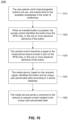
- the user initially selects a group of buttons to be used from the available group of buttons originally provided with the media system purchase. The user then inserts them into the available receptacles of the remote control unit in an order and arrangement preferred by the user. As mentioned earlier, the user may change the order of the buttons on the remote control, or exchange any button for a different one at any given time.
- the remote control identifies the button by its RFID chip, or by its one or more electronic elements through a sensing circuitry. For example, referring to the example of FIG. 7 , if the electronic element 500 is a resistor, the remote control will identify the button by determining its resistor value. In particular, in some embodiments, sensing circuitry 630, knowing the current/voltage output by power source 620, may determine the resistance of element 500 by sensing the voltage/current in the circuit completed when contacts 310 and 610 are engaged. Similarly, if the element 500 is a capacitor, the remote control will identify the button by reading the capacitance value of its capacitor.
- the button "carries" its user-perceivable label, or its intended functionality, regardless of its position on the remote control. This allows the user to change the position of a button while maintaining its intended functionality according to its user-perceivable label, or introduce new buttons with new labels and reposition them according to preference.
- the remote control transmits a signal to the media device.
- This signal is based at least in part on the RFID chip, or the one or more electrical elements of the button.
- the signal may contain information about the RFID chip or the electrical elements in the button.
- the signal may be a binary code corresponding to a relative parameter of the electrical element.
- the media device based on the received signal, identifies which interchangeable button is pressed by its RFID chip information or electrical element information.
- the media device may then identify the button's unique user-perceivable label according to a correlation table stored in a database.
- the table may contain unique correlation information between the button's RFID, or electrical element, and its corresponding user-perceivable label.
- the media service performs the indicated operation by sending a command to the network to request content or access a content provided corresponding to the user-perceivable label of the button, or by otherwise executing the command indicated by the user-perceivable label of the button.
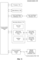
- Computer system 1100 can be used, for example, to implement method 1000 of FIG. 10 , or components of FIG. 1 .
- Computer system 1100 can be any computer capable of performing the functions described herein.
- Computer system 1100 can be any well-known computer capable of performing the functions described herein.
- Computer system 1100 includes one or more processors (also called central processing units, or CPUs), such as a processor 1104.
- processors also called central processing units, or CPUs
- Processor 1104 is connected to a communication infrastructure or bus 1106.
- One or more processors 1104 may each be a graphics processing unit (GPU).
- a GPU is a processor that is a specialized electronic circuit designed to process mathematically intensive applications.
- the GPU may have a parallel structure that is efficient for parallel processing of large blocks of data, such as mathematically intensive data common to computer graphics applications, images, videos, etc.
- Computer system 1100 also includes user input/output device(s) 1103, such as monitors, keyboards, pointing devices, etc., that communicate with communication infrastructure 1106 through user input/output interface(s) 1102.
- user input/output device(s) 1103 such as monitors, keyboards, pointing devices, etc.
- Computer system 1100 also includes a main or primary memory 1108, such as random access memory (RAM).
- Main memory 1108 may include one or more levels of cache.
- Main memory 1108 has stored therein control logic (i.e., computer software) and/or data.
- Computer system 1100 may also include one or more secondary storage devices or memory 1110.
- Secondary memory 1110 may include, for example, a hard disk drive 1112 and/or a removable storage device or drive 1114.
- Removable storage drive 1114 may be a floppy disk drive, a magnetic tape drive, a compact disk drive, an optical storage device, tape backup device, and/or any other storage device/drive.
- Removable storage drive 1114 may interact with a removable storage unit 1118.
- Removable storage unit 1118 includes a computer usable or readable storage device having stored thereon computer software (control logic) and/or data.
- Removable storage unit 1118 may be a floppy disk, magnetic tape, compact disk, DVD, optical storage disk, and/ any other computer data storage device.
- Removable storage drive 1114 reads from and/or writes to removable storage unit 1118 in a well-known manner.
- secondary memory 1110 may include other means, instrumentalities or other approaches for allowing computer programs and/or other instructions and/or data to be accessed by computer system 1100.
- Such means, instrumentalities or other approaches may include, for example, a removable storage unit 1122 and an interface 1120.
- the removable storage unit 1122 and the interface 1120 may include a program cartridge and cartridge interface (such as that found in video game devices), a removable memory chip (such as an EPROM or PROM) and associated socket, a memory stick and USB port, a memory card and associated memory card slot, and/or any other removable storage unit and associated interface.
- Computer system 1100 may further include a communication or network interface 1124.
- Communication interface 1124 enables computer system 1100 to communicate and interact with any combination of remote devices, remote networks, remote entities, etc. (individually and collectively referenced by reference number 1128).
- communication interface 1124 may allow computer system 1100 to communicate with remote devices 1128 over communications path 1126, which may be wired and/or wireless, and which may include any combination of LANs, WANs, the Internet, etc. Control logic and/or data may be transmitted to and from computer system 1100 via communication path 1126.
- a tangible apparatus or article of manufacture comprising a tangible computer useable or readable medium having control logic (software) stored thereon is also referred to herein as a computer program product or program storage device.
- control logic software stored thereon
- control logic when executed by one or more data processing devices (such as computer system 1100), causes such data processing devices to operate as described herein.
- references herein to "one embodiment,” “an embodiment,” “an example embodiment,” or similar phrases, indicate that the embodiment described can include a particular feature, structure, or characteristic, but every embodiment can not necessarily include the particular feature, structure, or characteristic. Moreover, such phrases are not necessarily referring to the same embodiment. Further, when a particular feature, structure, or characteristic is described in connection with an embodiment, it would be within the knowledge of persons skilled in the relevant art(s) to incorporate such feature, structure, or characteristic into other embodiments whether or not explicitly mentioned or described herein. Additionally, some embodiments can be described using the expression “coupled” and “connected” along with their derivatives. These terms are not necessarily intended as synonyms for each other.
- Coupled can also mean that two or more elements are not in direct contact with each other, but yet still co-operate or interact with each other.
Landscapes
- Engineering & Computer Science (AREA)
- Microelectronics & Electronic Packaging (AREA)
- Computer Hardware Design (AREA)
- Physics & Mathematics (AREA)
- General Physics & Mathematics (AREA)
- Theoretical Computer Science (AREA)
- Computer Networks & Wireless Communication (AREA)
- Selective Calling Equipment (AREA)
- Input From Keyboards Or The Like (AREA)
Claims (15)
- Fernsteuerung (140, 200) für ein Unterhaltungssystem (110), umfassend:zumindest eine austauschbare Platte, die zwei oder mehrere feste Knöpfe in vordefinierter Ordnung, die in einer Reihe angeordnet sind, aufweist, wobei die zwei oder mehreren festen Knöpfe nicht austauschbar sind, wobei jeder feste Knopf eine Anschlussbuchsenschnittstelle auf einer ersten Seite (320), eine für einen Benutzer wahrnehmbare Markierung (350) auf einer zweiten Seite (330) und ein darin eingebettetes elektrisches Element (500, 800) aufweist, wobei das elektrische Element (500, 800) des festen Knopfs dazu ausgelegt ist, der vom Benutzer wahrnehmbaren Markierung (350) des festen Knopfs zu entsprechen, und wobei das elektrische Element (500, 800) des festen Knopfes ein passives elektrisches Element, einen Transistor oder einen Gleichrichter umfasst;eine Vielzahl von austauschbaren Knöpfen (250, 300), wobei jeder austauschbare Knopf (250, 300) eine Anschlussbuchsenschnittstelle auf einer ersten Seite (320), eine für einen Benutzer wahrnehmbare Markierung (350) auf einer zweiten Seite (330) und ein oder mehrere elektrische Elemente (500, 800) darin aufweist, wobei das eine oder die mehreren elektrischen Elemente (500, 800) der vom Benutzer wahrnehmbaren Markierung (350) entspricht, und wobei ein elektrisches Element (500, 800) des einen oder der mehreren elektrischen Elemente (500, 800) ein passives elektrisches Element, einen Transistor oder einen Gleichrichter umfasst; undeine Plattform (210) mit einer Vielzahl von Anschlussbuchsen (240), wobei jede Anschlussbuchse (240) dazu ausgelegt ist, einen aus der Vielzahl von austauschbaren Knöpfen (250, 300) aufzunehmen, und wobei die Plattform ferner verschiedene Reihen von Anschlussbuchsen (220, 230) umfasst, wobei die zumindest eine austauschbare Platte, welche die zwei oder mehreren festen Knöpfe aufweist, in eine Reihe aus den verschiedenen Reihen eingebracht ist;wobei die Plattform (210) dazu ausgelegt ist, für eine Anschlussbuchse (240) mit einem austauschbaren Knopf (250, 300) oder einem damit in Eingriff gebrachten festen Knopf ein elektrisches Signal zumindest teilweise beruhend auf dem einen oder den mehreren elektrischen Elementen (500, 800) des austauschbaren Knopfs (250, 300) oder dem elektrischen Element (500, 800) des festen Knopfs bereitzustellen,wobei die vom Benutzer wahrnehmbare Markierung des festen Knopfs oder des austauschbaren Knopfs eine eindeutige, von einem Benutzer wahrnehmbare Markierung ist, die der Funktionalität des festen Knopfes oder des austauschbaren Knopfes dient, wobei das elektrische Element (500) dazu ausgelegt ist, funktional der eindeutigen, von einem Benutzer wahrnehmbaren Markierung (350) auf der zweiten Seite (330) des festen Knopfs oder des austauschbaren Knopfs zu entsprechen, wobei eine festgelegte eindeutige Korrelation zwischen der eindeutigen, von einem Benutzer wahrnehmbaren Markierung auf dem festen Knopf oder dem austauschbaren Knopf und dem elektrischen Element (500) vorliegt und die Plattform für jede Anschlussbuchse eine Abfühlschaltung (630) umfasst, die dazu ausgelegt ist, eine definierende Eigenschaft eines in der Anschlussbuchse eingebrachten elektrischen Elements zu erkennen.
- Fernsteuerung (140, 200) nach Anspruch 1, wobei das eine oder die mehreren elektrischen Elemente (500, 800) jedes austauschbaren Knopfs (250, 300) passive elektrische Elemente sind.
- Fernsteuerung (140, 200) nach Anspruch 1, wobei das eine oder die mehreren elektrischen Elemente (500, 800) jedes austauschbaren Knopfs (250, 300) aktive elektrische Elemente sind.
- Fernsteuerung (140, 200) nach Anspruch 1, wobei die Vielzahl von Anschlussbuchsen (240) zumindest vier Anschlussbuchsen (240) umfasst.
- Fernsteuerung (140, 200) nach Anspruch 1, wobei die Plattform (210) eine Platine innerhalb eines Gehäuses umfasst.
- Fernsteuerung (140, 200) nach Anspruch 1, wobei jeder austauschbare Knopf (250, 300) zwischen Anschlussbuchsen (240) neu angeordnet werden kann.
- Fernsteuerung (140, 200) nach Anspruch 1, wobei jede Anschlussbuchse (240) dazu ausgelegt ist, Leistung für das eine oder die mehreren elektrischen Elemente (500, 800) von einem aus der Vielzahl von darin eingebrachten austauschbaren Knöpfen (250, 300) bereitzustellen.
- Fernsteuerung (140, 200) nach Anspruch 1, wobei das elektrische Element (500, 800) jedes festen Knopfs eine Kombination aus einem passiven elektrischen Element und einem aktiven elektrischen Element umfasst.
- Fernsteuerung (140, 200) nach Anspruch 1, wobei:
die Anschlussbuchsenschnittstelle jedes austauschbaren Knopfs (250, 300) das eine oder die mehreren elektrischen Elemente (500, 800) darauf aufweist, wobei das eine oder die mehreren elektrischen Elemente (500, 800) der vom Benutzer wahrnehmbaren Markierung (350) entspricht/entsprechen. - Fernsteuerung (140, 200) nach Anspruch 9, wobei eine oder mehrere Elektroden einer Anschlussbuchse (240) der Plattform (210) und eine oder mehrere Elektroden des austauschbaren Knopfes (250, 300) fluchtend ausgerichtet sind.
- Fernsteuerung (140, 200) nach Anspruch 10, wobei die Anschlussbuchse (240) der Plattform (210) eine Anschlussbuchsenöffnung (650) umfasst und eine Form der Anschlussbuchsenöffnung (650) dazu ausgelegt ist, mit der Form der Anschlussbuchsenschnittstelle des austauschbaren Knopfs (250, 300) zusammenzupassen.
- Fernsteuerung (140, 200) nach Anspruch 1, wobei zumindest ein elektrisches Element (500, 800) des einen oder der mehreren Elemente (500, 800) jedes austauschbaren Knopfs (250, 300) einen darin eingebetteten Hochfrequenz-Identifizierungs-(RFID-)Chip umfasst und der RFID-Chip dazu ausgelegt ist, der vom Benutzer wahrnehmbaren Markierung (350) des austauschbaren Knopfs (250, 300) zu entsprechen.
- Fernsteuerung (140, 200) nach Anspruch 12, wobei eine Anschlussbuchse (240) der Plattform (210) dazu ausgelegt ist, Leistung für den RFID-Chip des darin eingebrachten austauschbaren Knopfs (250, 300) bereitzustellen.
- Fernsteuerung (140, 200) nach Anspruch 12, wobei der RFID-Chip als Read-Only-RFID-Markierung fungiert.
- Fernsteuerung (140, 200) nach Anspruch 14, wobei der RFID-Chip eine werksseitig zugewiesene Seriennummer, die der vom Benutzer wahrnehmbaren Markierung (350) des austauschbaren Knopfs (250, 300) entspricht, sendet.
Applications Claiming Priority (2)
| Application Number | Priority Date | Filing Date | Title |
|---|---|---|---|
| US15/477,275 US10217577B2 (en) | 2017-04-03 | 2017-04-03 | Remote control with configurable buttons |
| PCT/US2018/024507 WO2018187085A1 (en) | 2017-04-03 | 2018-03-27 | Remote control with configurable buttons |
Publications (3)
| Publication Number | Publication Date |
|---|---|
| EP3607573A1 EP3607573A1 (de) | 2020-02-12 |
| EP3607573A4 EP3607573A4 (de) | 2020-12-23 |
| EP3607573B1 true EP3607573B1 (de) | 2025-05-21 |
Family
ID=63671024
Family Applications (1)
| Application Number | Title | Priority Date | Filing Date |
|---|---|---|---|
| EP18781478.5A Active EP3607573B1 (de) | 2017-04-03 | 2018-03-27 | Fernbedienung mit konfigurierbaren tasten |
Country Status (3)
| Country | Link |
|---|---|
| US (1) | US10217577B2 (de) |
| EP (1) | EP3607573B1 (de) |
| WO (1) | WO2018187085A1 (de) |
Families Citing this family (3)
| Publication number | Priority date | Publication date | Assignee | Title |
|---|---|---|---|---|
| EP3439291B1 (de) * | 2016-03-30 | 2020-03-04 | Panasonic Intellectual Property Management Co., Ltd. | Steuergerät |
| USD963597S1 (en) | 2020-10-29 | 2022-09-13 | Gmi Holdings, Inc. | Remote control for an upward acting door operator |
| DE102021110607A1 (de) * | 2021-04-26 | 2022-10-27 | Semikron Elektronik Gmbh & Co. Kg | Gerät mit Funktionskomponente und Kunststoffgehäuseelement und Verfahren zur Überprüfung der Echtheit eines solches Geräts |
Family Cites Families (15)
| Publication number | Priority date | Publication date | Assignee | Title |
|---|---|---|---|---|
| US5150118A (en) * | 1989-05-08 | 1992-09-22 | Hewlett-Packard Company | Interchangeable coded key pad assemblies alternately attachable to a user definable keyboard to enable programmable keyboard functions |
| US5146615A (en) * | 1989-08-07 | 1992-09-08 | Ericsson Ge Mobile Communications Holding Inc. | Interchangeable control panels and keypads for radio transceivers and related process |
| WO1994028634A1 (en) * | 1993-05-21 | 1994-12-08 | Arthur D. Little Enterprises, Inc. | User-configurable control device |
| US5865546A (en) * | 1997-08-29 | 1999-02-02 | Compaq Computer Corporation | Modular keyboard for use in a computer system |
| US6965511B2 (en) * | 2001-10-10 | 2005-11-15 | Hewlett-Packard Development Company, L.P. | System and method for personalizing an electrical device |
| US6903662B2 (en) * | 2002-09-19 | 2005-06-07 | Ergodex | Computer input device with individually positionable and programmable input members |
| US7283067B2 (en) * | 2004-05-10 | 2007-10-16 | Espeed, Inc. | Fully configurable trading keyboard |
| US7334067B2 (en) | 2004-06-03 | 2008-02-19 | Sp Controls, Inc. | Programmable controller having reduced control key set |
| ITTV20040158A1 (it) | 2004-12-30 | 2005-03-30 | Nice Spa | Telecomando. |
| US20070101386A1 (en) * | 2005-11-01 | 2007-05-03 | Bftv Llc | Interactive developmental educational and entertainment system |
| EP1862886A3 (de) * | 2006-05-30 | 2012-12-05 | EBS Group Limited | Auftragseingabevorrichtung für ein elektronisches Handelssystem |
| US20110281652A1 (en) | 2009-02-02 | 2011-11-17 | Marc Laverdiere | Touch Music Player |
| FR2954548B1 (fr) | 2009-12-18 | 2013-10-04 | Schneider Electric Ind Sas | Systeme de dialogue homme-machine |
| US9524033B2 (en) * | 2013-03-08 | 2016-12-20 | International Business Machines Corporation | Wireless keyboard |
| TWI541683B (zh) * | 2015-03-12 | 2016-07-11 | 張耀仁 | 鍵盤及應用其之控制方法 |
-
2017
- 2017-04-03 US US15/477,275 patent/US10217577B2/en active Active
-
2018
- 2018-03-27 WO PCT/US2018/024507 patent/WO2018187085A1/en not_active Ceased
- 2018-03-27 EP EP18781478.5A patent/EP3607573B1/de active Active
Also Published As
| Publication number | Publication date |
|---|---|
| EP3607573A4 (de) | 2020-12-23 |
| EP3607573A1 (de) | 2020-02-12 |
| US20180286607A1 (en) | 2018-10-04 |
| WO2018187085A1 (en) | 2018-10-11 |
| US10217577B2 (en) | 2019-02-26 |
Similar Documents
| Publication | Publication Date | Title |
|---|---|---|
| US12407888B2 (en) | Digital media content management system and method | |
| US11482094B2 (en) | Electronic apparatus, remote control apparatus, control method thereof, and electronic system | |
| US9916062B2 (en) | Method, electronic device, and computer-readable recording medium for presenting application lists | |
| EP2975509B1 (de) | Verfahren und vorrichtung für desktopanzeige | |
| US20140095176A1 (en) | Electronic device, server and control method thereof | |
| EP2866159B1 (de) | Elektronische Vorrichtung und Verfahren zur Steuerung eines Bildschirms | |
| US20170127102A1 (en) | Method and electronic device for video recommendation | |
| CN104796780B (zh) | 信息展示方法、信道管理平台及终端 | |
| US10217577B2 (en) | Remote control with configurable buttons | |
| EP3629143A1 (de) | Vorrichtung und verfahren zur benachrichtigung verfügbarer vorrichtungen in einem inhaltsteilungsnetzwerk | |
| US9325754B2 (en) | Information processing device and information processing method | |
| US9459885B2 (en) | Smart card module and operating method thereof | |
| US10162484B2 (en) | Information-processing device, information-processing system, storage medium, and information-processing method | |
| EP3341790A1 (de) | System, verfahren und vorrichtung für eine farbsuche | |
| US20140304740A1 (en) | Method for displaying electronic program guide, electronic device, and computer readable medium | |
| CN112911345B (zh) | 推送媒资的方法及服务器 | |
| CN110166347A (zh) | 一种信息的分享方法、装置及设备 | |
| EP3702938A1 (de) | Elektronische vorrichtung und verfahren zur gewinnung von inhaltsinformationen auf basis einer angeschlossenen externen vorrichtung | |
| KR20200059558A (ko) | 사용자 프로파일을 생성하는 장치 및 그 장치를 포함하는 시스템 | |
| CN115759151A (zh) | 书籍管理方法、装置、存储介质及服务器 | |
| KR20210152739A (ko) | 전자장치 및 그 제어방법 | |
| CN110263188B (zh) | 媒体数据评分方法、装置及设备 | |
| CN103425528A (zh) | 电子设备及其信息处理方法 | |
| KR20150074602A (ko) | 디스플레이 장치 및 그의 동작 방법 | |
| CN104731715A (zh) | 一种数据块的排序方法及装置 |
Legal Events
| Date | Code | Title | Description |
|---|---|---|---|
| STAA | Information on the status of an ep patent application or granted ep patent |
Free format text: STATUS: THE INTERNATIONAL PUBLICATION HAS BEEN MADE |
|
| PUAI | Public reference made under article 153(3) epc to a published international application that has entered the european phase |
Free format text: ORIGINAL CODE: 0009012 |
|
| STAA | Information on the status of an ep patent application or granted ep patent |
Free format text: STATUS: REQUEST FOR EXAMINATION WAS MADE |
|
| 17P | Request for examination filed |
Effective date: 20191010 |
|
| AK | Designated contracting states |
Kind code of ref document: A1 Designated state(s): AL AT BE BG CH CY CZ DE DK EE ES FI FR GB GR HR HU IE IS IT LI LT LU LV MC MK MT NL NO PL PT RO RS SE SI SK SM TR |
|
| AX | Request for extension of the european patent |
Extension state: BA ME |
|
| RAP1 | Party data changed (applicant data changed or rights of an application transferred) |
Owner name: ROKU, INC. |
|
| DAV | Request for validation of the european patent (deleted) | ||
| DAX | Request for extension of the european patent (deleted) | ||
| A4 | Supplementary search report drawn up and despatched |
Effective date: 20201119 |
|
| RIC1 | Information provided on ipc code assigned before grant |
Ipc: H01H 13/83 20060101AFI20201113BHEP Ipc: G08C 17/02 20060101ALI20201113BHEP Ipc: G06K 19/07 20060101ALI20201113BHEP Ipc: H05K 5/00 20060101ALI20201113BHEP Ipc: G06K 19/077 20060101ALI20201113BHEP |
|
| STAA | Information on the status of an ep patent application or granted ep patent |
Free format text: STATUS: EXAMINATION IS IN PROGRESS |
|
| 17Q | First examination report despatched |
Effective date: 20221208 |
|
| GRAP | Despatch of communication of intention to grant a patent |
Free format text: ORIGINAL CODE: EPIDOSNIGR1 |
|
| STAA | Information on the status of an ep patent application or granted ep patent |
Free format text: STATUS: GRANT OF PATENT IS INTENDED |
|
| INTG | Intention to grant announced |
Effective date: 20241223 |
|
| GRAS | Grant fee paid |
Free format text: ORIGINAL CODE: EPIDOSNIGR3 |
|
| GRAA | (expected) grant |
Free format text: ORIGINAL CODE: 0009210 |
|
| STAA | Information on the status of an ep patent application or granted ep patent |
Free format text: STATUS: THE PATENT HAS BEEN GRANTED |
|
| AK | Designated contracting states |
Kind code of ref document: B1 Designated state(s): AL AT BE BG CH CY CZ DE DK EE ES FI FR GB GR HR HU IE IS IT LI LT LU LV MC MK MT NL NO PL PT RO RS SE SI SK SM TR |
|
| REG | Reference to a national code |
Ref country code: GB Ref legal event code: FG4D |
|
| REG | Reference to a national code |
Ref country code: CH Ref legal event code: EP |
|
| REG | Reference to a national code |
Ref country code: DE Ref legal event code: R096 Ref document number: 602018082117 Country of ref document: DE |
|
| REG | Reference to a national code |
Ref country code: IE Ref legal event code: FG4D |
|
| RAP4 | Party data changed (patent owner data changed or rights of a patent transferred) |
Owner name: ROKU, INC. |
|
| REG | Reference to a national code |
Ref country code: NL Ref legal event code: MP Effective date: 20250521 |
|
| PG25 | Lapsed in a contracting state [announced via postgrant information from national office to epo] |
Ref country code: PT Free format text: LAPSE BECAUSE OF FAILURE TO SUBMIT A TRANSLATION OF THE DESCRIPTION OR TO PAY THE FEE WITHIN THE PRESCRIBED TIME-LIMIT Effective date: 20250922 Ref country code: ES Free format text: LAPSE BECAUSE OF FAILURE TO SUBMIT A TRANSLATION OF THE DESCRIPTION OR TO PAY THE FEE WITHIN THE PRESCRIBED TIME-LIMIT Effective date: 20250521 Ref country code: FI Free format text: LAPSE BECAUSE OF FAILURE TO SUBMIT A TRANSLATION OF THE DESCRIPTION OR TO PAY THE FEE WITHIN THE PRESCRIBED TIME-LIMIT Effective date: 20250521 |
|
| REG | Reference to a national code |
Ref country code: LT Ref legal event code: MG9D |
|
| PG25 | Lapsed in a contracting state [announced via postgrant information from national office to epo] |
Ref country code: NO Free format text: LAPSE BECAUSE OF FAILURE TO SUBMIT A TRANSLATION OF THE DESCRIPTION OR TO PAY THE FEE WITHIN THE PRESCRIBED TIME-LIMIT Effective date: 20250821 Ref country code: GR Free format text: LAPSE BECAUSE OF FAILURE TO SUBMIT A TRANSLATION OF THE DESCRIPTION OR TO PAY THE FEE WITHIN THE PRESCRIBED TIME-LIMIT Effective date: 20250822 |
|
| PG25 | Lapsed in a contracting state [announced via postgrant information from national office to epo] |
Ref country code: NL Free format text: LAPSE BECAUSE OF FAILURE TO SUBMIT A TRANSLATION OF THE DESCRIPTION OR TO PAY THE FEE WITHIN THE PRESCRIBED TIME-LIMIT Effective date: 20250521 Ref country code: PL Free format text: LAPSE BECAUSE OF FAILURE TO SUBMIT A TRANSLATION OF THE DESCRIPTION OR TO PAY THE FEE WITHIN THE PRESCRIBED TIME-LIMIT Effective date: 20250521 |
|
| PG25 | Lapsed in a contracting state [announced via postgrant information from national office to epo] |
Ref country code: BG Free format text: LAPSE BECAUSE OF FAILURE TO SUBMIT A TRANSLATION OF THE DESCRIPTION OR TO PAY THE FEE WITHIN THE PRESCRIBED TIME-LIMIT Effective date: 20250521 |
|
| PG25 | Lapsed in a contracting state [announced via postgrant information from national office to epo] |
Ref country code: HR Free format text: LAPSE BECAUSE OF FAILURE TO SUBMIT A TRANSLATION OF THE DESCRIPTION OR TO PAY THE FEE WITHIN THE PRESCRIBED TIME-LIMIT Effective date: 20250521 |
|
| PG25 | Lapsed in a contracting state [announced via postgrant information from national office to epo] |
Ref country code: RS Free format text: LAPSE BECAUSE OF FAILURE TO SUBMIT A TRANSLATION OF THE DESCRIPTION OR TO PAY THE FEE WITHIN THE PRESCRIBED TIME-LIMIT Effective date: 20250821 |
|
| PG25 | Lapsed in a contracting state [announced via postgrant information from national office to epo] |
Ref country code: IS Free format text: LAPSE BECAUSE OF FAILURE TO SUBMIT A TRANSLATION OF THE DESCRIPTION OR TO PAY THE FEE WITHIN THE PRESCRIBED TIME-LIMIT Effective date: 20250921 |
|
| PG25 | Lapsed in a contracting state [announced via postgrant information from national office to epo] |
Ref country code: LV Free format text: LAPSE BECAUSE OF FAILURE TO SUBMIT A TRANSLATION OF THE DESCRIPTION OR TO PAY THE FEE WITHIN THE PRESCRIBED TIME-LIMIT Effective date: 20250521 |
|
| P01 | Opt-out of the competence of the unified patent court (upc) registered |
Free format text: CASE NUMBER: UPC_APP_0011767_3607573/2025 Effective date: 20251031 |
|
| REG | Reference to a national code |
Ref country code: AT Ref legal event code: MK05 Ref document number: 1797535 Country of ref document: AT Kind code of ref document: T Effective date: 20250521 |
|
| PG25 | Lapsed in a contracting state [announced via postgrant information from national office to epo] |
Ref country code: AT Free format text: LAPSE BECAUSE OF FAILURE TO SUBMIT A TRANSLATION OF THE DESCRIPTION OR TO PAY THE FEE WITHIN THE PRESCRIBED TIME-LIMIT Effective date: 20250521 Ref country code: SM Free format text: LAPSE BECAUSE OF FAILURE TO SUBMIT A TRANSLATION OF THE DESCRIPTION OR TO PAY THE FEE WITHIN THE PRESCRIBED TIME-LIMIT Effective date: 20250521 Ref country code: DK Free format text: LAPSE BECAUSE OF FAILURE TO SUBMIT A TRANSLATION OF THE DESCRIPTION OR TO PAY THE FEE WITHIN THE PRESCRIBED TIME-LIMIT Effective date: 20250521 |
|
| PG25 | Lapsed in a contracting state [announced via postgrant information from national office to epo] |
Ref country code: CZ Free format text: LAPSE BECAUSE OF FAILURE TO SUBMIT A TRANSLATION OF THE DESCRIPTION OR TO PAY THE FEE WITHIN THE PRESCRIBED TIME-LIMIT Effective date: 20250521 |
|
| PG25 | Lapsed in a contracting state [announced via postgrant information from national office to epo] |
Ref country code: EE Free format text: LAPSE BECAUSE OF FAILURE TO SUBMIT A TRANSLATION OF THE DESCRIPTION OR TO PAY THE FEE WITHIN THE PRESCRIBED TIME-LIMIT Effective date: 20250521 |
|
| PG25 | Lapsed in a contracting state [announced via postgrant information from national office to epo] |
Ref country code: RO Free format text: LAPSE BECAUSE OF FAILURE TO SUBMIT A TRANSLATION OF THE DESCRIPTION OR TO PAY THE FEE WITHIN THE PRESCRIBED TIME-LIMIT Effective date: 20250521 Ref country code: SK Free format text: LAPSE BECAUSE OF FAILURE TO SUBMIT A TRANSLATION OF THE DESCRIPTION OR TO PAY THE FEE WITHIN THE PRESCRIBED TIME-LIMIT Effective date: 20250521 |
|
| PG25 | Lapsed in a contracting state [announced via postgrant information from national office to epo] |
Ref country code: IT Free format text: LAPSE BECAUSE OF FAILURE TO SUBMIT A TRANSLATION OF THE DESCRIPTION OR TO PAY THE FEE WITHIN THE PRESCRIBED TIME-LIMIT Effective date: 20250521 |
|
| REG | Reference to a national code |
Ref country code: DE Ref legal event code: R097 Ref document number: 602018082117 Country of ref document: DE |
|
| PLBE | No opposition filed within time limit |
Free format text: ORIGINAL CODE: 0009261 |
|
| STAA | Information on the status of an ep patent application or granted ep patent |
Free format text: STATUS: NO OPPOSITION FILED WITHIN TIME LIMIT |
|
| REG | Reference to a national code |
Ref country code: CH Ref legal event code: L10 Free format text: ST27 STATUS EVENT CODE: U-0-0-L10-L00 (AS PROVIDED BY THE NATIONAL OFFICE) Effective date: 20260402 |
|
| PGFP | Annual fee paid to national office [announced via postgrant information from national office to epo] |
Ref country code: GB Payment date: 20260323 Year of fee payment: 9 |
|
| PGFP | Annual fee paid to national office [announced via postgrant information from national office to epo] |
Ref country code: DE Payment date: 20260217 Year of fee payment: 9 |
|
| 26N | No opposition filed |
Effective date: 20260224 |