EP3607263B1 - Anzeigevorrichtung für eine einsatzkraft zur anzeige von informations-inhalten verschiedener informations-typen eines führungssystems - Google Patents
Anzeigevorrichtung für eine einsatzkraft zur anzeige von informations-inhalten verschiedener informations-typen eines führungssystems Download PDFInfo
- Publication number
- EP3607263B1 EP3607263B1 EP18735257.0A EP18735257A EP3607263B1 EP 3607263 B1 EP3607263 B1 EP 3607263B1 EP 18735257 A EP18735257 A EP 18735257A EP 3607263 B1 EP3607263 B1 EP 3607263B1
- Authority
- EP
- European Patent Office
- Prior art keywords
- segments
- information
- indicator device
- deployment
- operator
- Prior art date
- Legal status (The legal status is an assumption and is not a legal conclusion. Google has not performed a legal analysis and makes no representation as to the accuracy of the status listed.)
- Active
Links
Images


Classifications
-
- G—PHYSICS
- G08—SIGNALLING
- G08B—SIGNALLING OR CALLING SYSTEMS; ORDER TELEGRAPHS; ALARM SYSTEMS
- G08B5/00—Visible signalling systems, e.g. personal calling systems, remote indication of seats occupied
- G08B5/22—Visible signalling systems, e.g. personal calling systems, remote indication of seats occupied using electric transmission; using electromagnetic transmission
- G08B5/36—Visible signalling systems, e.g. personal calling systems, remote indication of seats occupied using electric transmission; using electromagnetic transmission using visible light sources
-
- G—PHYSICS
- G09—EDUCATION; CRYPTOGRAPHY; DISPLAY; ADVERTISING; SEALS
- G09G—ARRANGEMENTS OR CIRCUITS FOR CONTROL OF INDICATING DEVICES USING STATIC MEANS TO PRESENT VARIABLE INFORMATION
- G09G3/00—Control arrangements or circuits, of interest only in connection with visual indicators other than cathode-ray tubes
- G09G3/001—Control arrangements or circuits, of interest only in connection with visual indicators other than cathode-ray tubes using specific devices not provided for in groups G09G3/02 - G09G3/36, e.g. using an intermediate record carrier such as a film slide; Projection systems; Display of non-alphanumerical information, solely or in combination with alphanumerical information, e.g. digital display on projected diapositive as background
-
- F—MECHANICAL ENGINEERING; LIGHTING; HEATING; WEAPONS; BLASTING
- F41—WEAPONS
- F41G—WEAPON SIGHTS; AIMING
- F41G1/00—Sighting devices
-
- F—MECHANICAL ENGINEERING; LIGHTING; HEATING; WEAPONS; BLASTING
- F41—WEAPONS
- F41G—WEAPON SIGHTS; AIMING
- F41G9/00—Systems for controlling missiles or projectiles, not provided for elsewhere
-
- G—PHYSICS
- G02—OPTICS
- G02B—OPTICAL ELEMENTS, SYSTEMS OR APPARATUS
- G02B27/00—Optical systems or apparatus not provided for by any of the groups G02B1/00 - G02B26/00, G02B30/00
- G02B27/01—Head-up displays
- G02B27/017—Head mounted
- G02B27/0172—Head mounted characterised by optical features
-
- G—PHYSICS
- G06—COMPUTING OR CALCULATING; COUNTING
- G06F—ELECTRIC DIGITAL DATA PROCESSING
- G06F1/00—Details not covered by groups G06F3/00 - G06F13/00 and G06F21/00
- G06F1/16—Constructional details or arrangements
- G06F1/1601—Constructional details related to the housing of computer displays, e.g. of CRT monitors, of flat displays
- G06F1/1605—Multimedia displays, e.g. with integrated or attached speakers, cameras, microphones
-
- G—PHYSICS
- G06—COMPUTING OR CALCULATING; COUNTING
- G06F—ELECTRIC DIGITAL DATA PROCESSING
- G06F1/00—Details not covered by groups G06F3/00 - G06F13/00 and G06F21/00
- G06F1/16—Constructional details or arrangements
- G06F1/1613—Constructional details or arrangements for portable computers
- G06F1/1633—Constructional details or arrangements of portable computers not specific to the type of enclosures covered by groups G06F1/1615 - G06F1/1626
- G06F1/1637—Details related to the display arrangement, including those related to the mounting of the display in the housing
- G06F1/1641—Details related to the display arrangement, including those related to the mounting of the display in the housing the display being formed by a plurality of foldable display components
-
- G—PHYSICS
- G06—COMPUTING OR CALCULATING; COUNTING
- G06F—ELECTRIC DIGITAL DATA PROCESSING
- G06F3/00—Input arrangements for transferring data to be processed into a form capable of being handled by the computer; Output arrangements for transferring data from processing unit to output unit, e.g. interface arrangements
- G06F3/14—Digital output to display device ; Cooperation and interconnection of the display device with other functional units
-
- F—MECHANICAL ENGINEERING; LIGHTING; HEATING; WEAPONS; BLASTING
- F41—WEAPONS
- F41G—WEAPON SIGHTS; AIMING
- F41G3/00—Aiming or laying means
- F41G3/04—Aiming or laying means for dispersing fire from a battery ; for controlling spread of shots; for coordinating fire from spaced weapons
-
- F—MECHANICAL ENGINEERING; LIGHTING; HEATING; WEAPONS; BLASTING
- F41—WEAPONS
- F41G—WEAPON SIGHTS; AIMING
- F41G3/00—Aiming or laying means
- F41G3/14—Indirect aiming means
- F41G3/16—Sighting devices adapted for indirect laying of fire
- F41G3/165—Sighting devices adapted for indirect laying of fire using a TV-monitor
-
- G—PHYSICS
- G02—OPTICS
- G02B—OPTICAL ELEMENTS, SYSTEMS OR APPARATUS
- G02B27/00—Optical systems or apparatus not provided for by any of the groups G02B1/00 - G02B26/00, G02B30/00
- G02B27/01—Head-up displays
- G02B27/0101—Head-up displays characterised by optical features
- G02B2027/0132—Head-up displays characterised by optical features comprising binocular systems
-
- G—PHYSICS
- G02—OPTICS
- G02B—OPTICAL ELEMENTS, SYSTEMS OR APPARATUS
- G02B27/00—Optical systems or apparatus not provided for by any of the groups G02B1/00 - G02B26/00, G02B30/00
- G02B27/01—Head-up displays
- G02B27/017—Head mounted
- G02B2027/0178—Eyeglass type
Definitions
- the present invention relates to a display device for an emergency worker for displaying information content of various types of information in a guidance system.
- the present invention also relates to an arrangement with a guidance system for guiding a plurality of emergency services and a plurality of display devices.
- clocks are known as display devices via which an information system or guidance system can transmit information to a user of the clock.
- a watch as an information receiver has the disadvantage that the user of the watch has to direct his attention to the watch in order to receive the information presented by the watch. This allows the user to be distracted from other activities or tasks, in particular during an assignment. The responsiveness of the user when looking at the watch to receive the information is also disadvantageously reduced.
- the document WO 02/31578 A1 shows an information system with a signal detection device that detects signals reflected back from at least one eye having a retina, with an output device that provides information in cooperation with an information device and as a function of the detected signals, the output device comprising a scanning projection device that at least some of the information is projected onto the retina.
- the signal acquisition device comprises a scanning scanning device which, in a first scanning process, carries out at least partial acquisition of a retinal reflex image of the retina and, in a later scanning process, undertakes a less extensive acquisition of the retinal reflex image.
- the document US 2015/061974 A1 shows a head-mounted display that enables a user to visually recognize a virtual image and an external scene.
- a display device for an emergency worker for displaying information content of various types of information in a guidance system comprises a display that can be worn by the emergency responder and has a plurality of visually distinguishable segments, each of the segments being assigned at least one of the information types, the respective segment for visual output of current information content of the information type assigned to the segment is set up.
- the display device comprises a control unit, which can be coupled to the guidance system, for controlling the display.
- the display device is designed as a mask which can be worn in front of the face of the emergency worker, the visually distinguishable segments being arranged in a peripheral field of vision of the emergency worker when the mask is worn by the emergency worker.
- the display device is designed as glasses or glasses extension that can be worn by the emergency worker, the visually distinguishable segments being arranged in a peripheral field of vision of the emergency worker when the glasses or the glasses extension are worn.
- a number of the segments of the plurality of visually distinguishable segments are set up to map an area outside of the operator's visual image, in particular an area behind the operator, by means of the visual output of the information content of the information types assigned to the segments of the number.
- the information types include, for example, one or more navigation points, one or more navigation areas, one or more threats to the emergency services, predetermined goals and / or active assignments by the guidance system, red force tracking and / or blue force -Tracking.
- the different types of information are preferably assigned different colors in the visual representation by the segments.
- the visually distinguishable segments are in particular visually distinguishable for the emergency worker, that is to say for a human user.
- the individual segments of the display can preferably be controlled individually by the control unit.
- an information type is a threat and the threat is in the left area of the field of vision of the emergency services
- a segment in the display in the left area that is assigned to this information type will light up red.
- the emergency services especially in their peripheral field of vision, are signaled by the current information content of the red light in the segment that there is a threat to the left in front of them.
- the present display device significantly increases the effectiveness of the emergency personnel during an operation, since it is possible to provide current information content of various types of information from the guidance system to the emergency personnel via the display.
- the present display device supports the emergency worker through peripheral perception with minimal restriction of the emergency worker.
- the proposed display device can also accelerate the command process and the control process between the guidance system and the emergency services.
- the display of the display device and the control unit of the display device can be produced inexpensively, are energy-efficient and are only light in weight for the emergency services.
- the display is preferably designed as a display that can be worn on the head of the emergency responder.
- the control unit can be coupled or connected to the guidance system in particular via one or more communication links.
- control unit can be coupled to the control system via at least two separate, independent communication links to create redundant communication lines.
- Examples of a communication standard that can be used for this purpose include GPRS, UMTS, LTE, WLAN, Bluetooth, TETRA radio, LoRa and ZigBee.
- the task force is, for example, a soldier. Further examples of emergency services are fire fighters, police officers, THW employees and the like.
- the management system can also be referred to as a control center or information system.
- the display can also be referred to as a segment display.
- control unit is set up to receive signals having the current information content for the information types from the guidance system and to control the display by means of control commands generated as a function of the received signals for visual output of the current information content .
- the display device can use the signals to receive the current information content for the various types of information from the guidance system.
- the control unit then controls the display accordingly that all received Information content, in particular in real time, is displayed to the user via the segments of the display.
- control unit is set up to assign the information types to the segments of the display.
- the control unit can advantageously control the assignment of the respective information type to the segments. If, for example, the position of a threat changes relative to the emergency worker, the control unit will map the threat information type to a change in the assigned segment in accordance with this change in location. That is, if the threat moves, for example, from a left area relative to the emergency worker into a central area relative to the emergency worker, the control unit will move the segment assigned for the information type threat from a left area of the display to a central one Change the area of the display.
- control unit is also set up to determine a display type for the respective information type assigned to one of the segments.
- control unit in this embodiment is set up to change a color and / or a pulse duration of the segment in the context of determining the display type. If, for example, the information type represents a threat, the control unit can determine the color red for the information type. If the threat to the emergency services comes closer, the control unit can determine that the red illuminated segment is also pulsing. With each further approach of the threat to the emergency services, the frequency of the pulsating red segment can be increased by the control unit.
- control unit is set up to transfer the information types to the segments as a function of one of the Management system transmitted external control command to assign a certain head alignment of the emergency services and / or a determined position of the emergency services.
- the control unit can determine a specific segment for visual output for the output of this command or this assignment. Furthermore, the control unit can determine the assignment of the information types to the segments as a function of a change in the head alignment of the emergency services. If, for example, as shown above, there is a threat in the left field of vision of the emergency services, a corresponding segment will light up red in the left area of the display. If the emergency services then moves their head to the left and the threat does not change its position, the control unit will assign a segment in the central area of the display for the information type threat. Correspondingly, the control unit can also change the assignment of the information types to the segments as a function of a change in the position of the emergency worker, for example a satellite-determined position of the emergency worker.
- the display device comprises a determination unit for determining the head orientation of the emergency worker, the determination unit having a compass and / or a gyrometer.
- the display device comprises a determination unit for determining the position of the emergency worker.
- the determination unit can for example include sensors such as gyro sensors, acceleration sensors, pedometers, altimeters or the like.
- control unit is set up to assign a first information type and at least one second information type to a specific segment of the plurality of segments.
- control unit can also assign several types of information to a specific segment.
- control unit can not only assign a blue force display to a segment (for example using the color blue), but also assign a motion vector of the blue force (for example using an arrow shown in the segment).
- the plurality of visually distinguishable segments are arranged in a row.
- the row of segments can be arranged in particular near the eyes, for example a little above the eyes or a little below the eyes, in a peripheral field of vision of the operator.
- the arrangement of the row of segments in the peripheral field of vision of the emergency personnel has the advantage that, compared to a solution outside of the field of vision, a high degree of reaction possibility is provided for the user.
- the arrangement of the row of segments in the peripheral field of vision of the emergency worker also has the advantage that, compared to an arrangement in an active field of vision of the emergency worker, a minimal restriction is created for the emergency worker.
- the plurality of visually distinguishable segments are arranged in a matrix.
- the number of rows in the matrix is significantly less than the number of columns in the matrix, so that the display with the segments arranged in a matrix can be arranged in a peripheral area of the field of vision of the emergency worker.
- the row of segments is set up to depict a horizontal visual image of the emergency worker by means of the visual output of the information content of the information types assigned to the segments.
- the display device is designed as a mask that can be worn in front of the face of the emergency worker.
- the visually distinguishable segments are arranged in a peripheral field of vision of the operator when the mask is worn by the operator.
- the mask can be connected to two headphones for the ears of the emergency worker via straps and via at least one further strap for tensioning the headphones and the mask over the head.
- the mask can furthermore comprise an embedded microphone, so that the emergency worker can communicate with the guidance system via voice via the microphone and the headphones.
- the visual underscriptable segments are arranged in such a way that they are arranged exclusively in the peripheral field of vision of the emergency worker and in particular not in the active field of vision of the emergency worker.
- the segments are therefore preferably exclusively in the peripheral field of vision and not in the active field of vision, that is to say the user can recognize them, but the segments and their display disturb the emergency services only minimally.
- the display device is designed as glasses or glasses extension that can be worn by the emergency worker, the visually distinguishable segments being arranged in a peripheral field of vision of the emergency worker when the glasses or the glasses extension are worn.
- the segments can be arranged above the glasses of the glasses.
- the segments can be plugged onto glasses, for example, or connected to a frame that can be displaced in the x direction, in the y direction and / or in the z direction.
- the glasses or the glasses extension are designed in such a way that an alignment of the segments in the x-direction, in the y-direction and in the z-direction can be set.
- the visually distinguishable segments are arranged in a ring-shaped manner.
- the segments form a ring.
- the segments of the display are preferably flexible.
- the segments which are arranged in a ring-shaped manner, are integrated in an aiming system of a weapon or in a telescopic sight.
- the segments which are arranged in a ring-shaped manner, are arranged in a reconnaissance device or in binoculars.
- a number of the segments of the plurality of visually distinguishable segments are set up to map an area outside of the operator's visual image, in particular an area behind the operator, by means of the visual output of the information content of the information types assigned to the segments of the number.
- each segment of the two outer segments of the plurality of visually distinguishable segments is set up to cover a certain area outside of the operator's visual image, in particular an area behind the operator, by means of the visual output of the information content assigned to the respective segment Map information types.
- the left outer segment can be assigned to a left area behind the operator, whereas the right outer segment can be assigned to a right area behind the operator.
- the outer segments can be made visible to the emergency worker via the outer segments, but he can even perceive different areas outside of his field of vision in a differentiated manner.
- the plurality of visually distinguishable segments are arranged on a helmet for the emergency services or integrated in the helmet.
- the display device comprises a control device.
- the control device preferably comprises an interface device or data interface which is set up at least for coupling the display.
- the interface device can also comprise one or more interfaces, for example a USB interface and / or a Bluetooth interface, which are set up for coupling external devices or sensors.
- control device can also include a data processing device, such as a microprocessor, which, for example, integrates the control unit.
- a data processing device such as a microprocessor, which, for example, integrates the control unit.
- control device preferably comprises a communication device for data communication with at least the guidance system.
- One or more sensors can also be connected via the aforementioned interface device or data interface. Examples of such sensors include a gyroscope, a light sensor, a microphone, an ambient noise suppression and / or a compass.
- the respective unit for example the control unit, can be implemented in terms of hardware and / or also in terms of software.
- the unit can be designed as a device or as part of a device, for example as a computer or as a microprocessor.
- the unit can be designed as a computer program product, as a function, as a routine, as part of a program code or as an executable object.
- a computer program product such as a computer program means, for example, can be provided or delivered as a storage medium such as a memory card, USB stick, CD-ROM, DVD, or also in the form of a downloadable file from a server in a network. This can take place, for example, in a wireless communication network by transmitting a corresponding file with the computer program product or the computer program means.
- an arrangement is provided with a guidance system for guiding a plurality of emergency services and a plurality of display devices proposed, one of the display devices being assigned to the respective emergency services.
- the respective display device is designed according to the first aspect or one of the embodiments of the first aspect.
- FIG. 1 a schematic block diagram of a first exemplary embodiment of a display device 10 for an emergency worker is shown.
- the display device 10 of Fig. 1 is designed as a textile mask 14 that can be worn in front of the face of the emergency worker, which is used to display information content of various types of information of a guidance system 1 (see FIG Fig. 6 ) is set up.
- the mask 14 of Fig. 1 a display 20 comprising a plurality of visually distinguishable segments 21-28.
- the visually distinguishable segments 21-28 of the display 20 are arranged in a peripheral field of view of the emergency worker when the mask 14 is worn by the emergency worker.
- the segments 21-28 can in particular be controlled individually.
- Each of the segments 21-28 is assigned to at least one of the information types.
- the respective segments 21-28 are set up for the visual output of a current information content of the information type assigned to the segment 21-28.
- the mask 14 of the Fig. 1 further comprises a control unit 30, which is connected to the guidance system 1 (see FIG Fig. 6 ) can be coupled for the exchange of data and is set up to control the display 20.
- the control unit 30 is set up in particular to generate signals, for example radio signals, having the current information content for the information types of to receive the guidance system 1 and to control the display 20 by means of control commands generated as a function of the received signals for the visual output of the current information content.
- the control unit 30 is, for example, part of a control device such as a microprocessor.
- the control unit 30 is woven into the textile of the mask 14. The same applies to units 40-70 discussed below.
- control unit 30 can also be set up to assign the information types to the segments 21-28. This assignment can in particular also take place dynamically, for example as a function of a position of the emergency worker and / or a head alignment of the emergency worker.
- control unit 30 is set up to determine a display type for the respective information type by the assigned segments 21 - 28.
- the type of display includes, for example, the color of the display and / or a pulse frequency of the display.
- the mask 14 further comprises a determination unit 40 and a determination unit 50.
- the determination unit 40 is set up to determine the head orientation of the emergency worker.
- the determination unit 40 includes, for example, a compass and / or a gyrometer.
- the determination unit 50 is set up to determine the position of the emergency worker.
- the determination unit 50 includes a GPS receiver.
- the mask 14 further comprises an air passage 60 and a microphone 70.
- the mask 14 is preferably connected via a number of straps 73 to two headphones 71, 72 for the ears of the emergency worker and via further straps 73 for tensioning the headphones 71, 72 and the mask 14 over the head of the emergency worker.
- the emergency worker can communicate with the guidance system 1 by voice. the When the mask 14 is worn, segments 21-28 of the display 20 are arranged in such a way that they are arranged exclusively in the peripheral field of vision of the emergency worker and in particular not in the active field of vision of the emergency worker.
- a connecting device 74 for example a buckle, is provided to connect the straps 73 to the back of the emergency worker's head.
- a data interface 100 can be provided on the connecting device 74.
- the data interface is, for example, a USB interface.
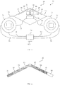
- FIG. 10 is an enlarged view of the display 20 of the display device 10 of FIG Fig. 1 shown.
- the Fig. 2 shows that the segments 21-27 have different hatching. Each different hatching represents a different type of information.
- the segment 28 is in the example of Fig. 2 provided for the display of external commands of the management system 1 for the emergency services and in the Fig. 2 provided without hatching.
- the segments 21-28 are arranged in a row, which can also have a corner or curvature.
- the row of segments 21-28 preferably forms a horizontal visual image of the emergency personnel by means of the visual output of the information content of the information types assigned to the segments 21-28.
- Fig. 3 shows a schematic block diagram of a second exemplary embodiment of a display device 10 for an emergency worker.
- the display device 10 of Fig. 3 is designed as a pair of glasses 15 for the emergency services.
- the display 20 of the display device of Fig. 3 comprises two rows of segments 21-24 and 25-28. With regard to the features and properties of segments 21-28 of the display 20 of FIG Fig. 3 this applies to segments 21 - 28 of Fig. 1 Said accordingly.
- the glasses 15 comprise a fixing device 110 for fixing the glasses 15.
- Stabilizing plates 91, 92 for supporting the two rows on segments 21-24 and 25-28 are attached to the fixing device 110.
- the arrows P1 and P2 illustrate a possibility of setting the rows of segments 21-24 and 25-28 in the y-direction and in the z-direction.
- the fixing device 110 preferably includes a setting option in the x direction.
- the control unit 30 of the display device 10 of Fig. 3 is coupled to a data interface 100 and can be connected to a determination unit 40, a determination unit 50 and a light sensor 80 via communication links 111.
- Fig. 4 shows a schematic block diagram of a third exemplary embodiment of a display device 10 for an emergency worker.
- the display device 10 of Fig. 4 is designed as a directional system 16 for a weapon.
- the display 20 with the visually distinguishable segments 21-28 of the display device 10 of FIG Fig. 4 is ring-shaped.
- the ring can thus be integrated into a telescopic sight at segments 21-28, for example.
- segments 21-28 of the display 20 of FIG Fig. 4 this applies to segments 21 - 28 of Fig. 1 Said accordingly.
- the annular display 20 of the Fig. 4 is mounted on a weapon part 130.
- the evaluation unit 30, a data interface 100 and an energy supply device 120, for example an accumulator, are arranged on the weapon part 130.
- Further devices that can also be arranged on the weapon part 130 are, for example, with reference to the Fig. 1 and 3 and comprise, for example, a determination unit 50 and a communication device for communication with the guidance system 1.
- Fig. 5 shows a schematic block diagram of a fourth exemplary embodiment of a display device 10 for an emergency worker.
- the display device 10 of Fig. 5 comprises two rings of segments 21 - 28 for the two eyes of the Emergency worker. With regard to the features and properties of the segments 21-28 of the display 20 of FIG Fig. 5 this applies to segments 21 - 28 of Fig. 1 Said accordingly.
- the two rings on segments 21 - 28 are attached to a carrier part 140.
- the control unit 30, an energy supply device 120 and a communication device 150 for communication with the guidance system 1 are provided on the carrier part 140.
- Further units that can be fastened to the carrier part 140 result, for example, from the Fig. 1 , 3 and 4 .
- FIG Fig. 1 , 3 , 4th and 5 Further exemplary embodiments for display devices 10 result from combinations of the exemplary embodiments in FIG Fig. 1 , 3 , 4th and 5 .
- Fig. 6 shows a schematic block diagram of an exemplary embodiment of an arrangement with a guidance system 1 for guiding a plurality of emergency services and a plurality of display devices 11, 12, 13.
- the guidance system 1 can be coupled to the display devices 11, 12 and 13 via communication links K1, K2, K3.
- the respective display device 11, 12, 13 is assigned to a respective emergency worker.
- the respective communication connection K1, K2, K3, for example the communication connection K1 between the guidance system 1 and the display device 11, is designed, for example, as a radio interface.
- the respective display device 11, 12, 13 is, for example, like one of the display devices 10 of FIG Fig. 1 , 3 , 4th or 5 educated.
Landscapes
- Engineering & Computer Science (AREA)
- Physics & Mathematics (AREA)
- Theoretical Computer Science (AREA)
- General Engineering & Computer Science (AREA)
- General Physics & Mathematics (AREA)
- Computer Hardware Design (AREA)
- Human Computer Interaction (AREA)
- Optics & Photonics (AREA)
- Multimedia (AREA)
- Electromagnetism (AREA)
- User Interface Of Digital Computer (AREA)
- Controls And Circuits For Display Device (AREA)
- Control Of Indicators Other Than Cathode Ray Tubes (AREA)
- Audible And Visible Signals (AREA)
Description
- Die vorliegende Erfindung betrifft eine Anzeigevorrichtung für eine Einsatzkraft zur Anzeige von Informations-Inhalten verschiedener Informations-Typen eines Führungssystems. Des Weiteren betrifft die vorliegende Erfindung eine Anordnung mit einem Führungssystem zum Führen einer Mehrzahl von Einsatzkräften und einer Mehrzahl von Anzeigevorrichtungen.
- Es sind beispielsweise Uhren als Anzeigevorrichtungen bekannt, über die ein Informationssystem oder Führungssystem Informationen an einen Nutzer der Uhr übertragen kann. Eine solche Uhr als Informationsempfänger hat allerdings den Nachteil, dass der Nutzer der Uhr zur Aufnahme der durch die Uhr dargestellten Informationen seine Aufmerksamkeit auf die Uhr richten muss. Hierdurch kann der Nutzer von anderen Tätigkeiten oder Aufgaben, insbesondere während eines Einsatzes, abgelenkt werden. Auch die Reaktionsfähigkeit des Nutzers wird beim Blicken auf die Uhr zur Aufnahme der Informationen nachteiliger Weise vermindert.
- Das Dokument
WO 02/31578 A1 - Das Dokument
US 2015/061974 A1 zeigt eine am Kopf montierte Anzeige, die es einem Benutzer ermöglicht, ein virtuelles Bild und eine externe Szenerie visuell zu erkennen. - Gemäß einem ersten Aspekt wird eine Anzeigevorrichtung für eine Einsatzkraft zur Anzeige von Informations-Inhalten verschiedener Informations-Typen eines Führungssystems vorgeschlagen. Die Anzeigevorrichtung umfasst ein durch die Einsatzkraft tragbares Display aufweisend eine Mehrzahl von visuell unterscheidbaren Segmenten, wobei einem jeden der Segmente zumindest einer der Informations-Typen zugewiesen ist, wobei das jeweilige Segment zur visuellen Ausgabe eines aktuellen Informations-Inhalts des dem Segment zugewiesenen Informations-Typs eingerichtet ist. Ferner umfasst die Anzeigevorrichtung eine mit dem Führungssystem koppelbare Ansteuer-Einheit zum Ansteuern des Displays. Die Anzeigevorrichtung ist als eine vor dem Gesicht der Einsatzkraft tragbare Maske ausgebildet, wobei die visuell unterscheidbaren Segmente bei einem Tragen der Maske durch die Einsatzkraft in einem peripheren Sichtfeld der Einsatzkraft angeordnet sind. Alternativ ist die Anzeigevorrichtung als eine durch die Einsatzkraft tragbare Brille oder Brillen-Erweiterung ausgebildet, wobei die visuell unterscheidbaren Segmente bei einem Tragen der Brille oder der Brillen-Erweiterung in einem peripheren Sichtfeld der Einsatzkraft angeordnet sind. Eine Anzahl der Segmente der Mehrzahl von visuell unterscheidbaren Segmenten ist dazu eingerichtet, einen Bereich außerhalb des Sichtbildes der Einsatzkraft, insbesondere einen Bereich hinter der Einsatzkraft, mittels der visuellen Ausgabe der Informations-Inhalte der den Segmenten der Anzahl zugewiesenen Informations-Typen abzubilden.
- Die Informations-Typen umfassen beispielsweise einen oder mehrere Navigations-Punkte, einen oder mehrere Navigationsbereiche, eine oder mehrere Bedrohungen für die Einsatzkraft, vorbestimmte Ziele und/oder aktive Zuweisungen durch das Führungssystem, ein Red-Force-Tracking und/oder ein Blue-Force-Tracking. Vorzugsweise sind den unterschiedlichen Informations-Typen unterschiedliche Farben bei der visuellen Darstellung durch die Segmente zugeordnet.
- Die visuell unterscheidbaren Segmente sind insbesondere für die Einsatzkraft, das heißt für einen menschlichen Benutzer, visuell unterscheidbar. Vorzugsweise sind die einzelnen Segmente des Displays durch die Ansteuer-Einheit einzeln ansteuerbar.
- Wenn beispielsweise ein Informations-Typ eine Bedrohung ist und sich die Bedrohung im linken Bereich des Sichtbereichs der Einsatzkraft befindet, so wird ein in dem Display im linken Bereich angeordnetes Segment, das diesem Informations-Typ zugeordnet ist, rot leuchten. Damit ist der Einsatzkraft, insbesondere in seinem peripheren Sichtfeld durch den aktuellen Informations-Inhalt des roten Leuchtens des Segments signalisiert, dass sich links vor ihr eine Bedrohung befindet.
- Durch die vorliegende Anzeigevorrichtung wird die Effektivität der Einsatzkraft während eines Einsatzes deutlich erhöht, da es möglich ist, aktuelle Informations-Inhalte verschiedener Informations-Typen von dem Führungssystem der Einsatzkraft über das Display unmittelbar bereitzustellen. Durch die vorliegende Anzeigevorrichtung wird die Einsatzkraft durch periphere Wahrnehmung bei minimaler Einschränkung der Einsatzkraft unterstützt. Auch können durch die vorgeschlagene Anzeigevorrichtung der Befehlsprozess und der Steuerprozess zwischen dem Führungssystem und der Einsatzkraft beschleunigt werden.
- Das Display der Anzeigevorrichtung und die Ansteuer-Einheit der Anzeigevorrichtung sind kostengünstig herstellbar, energieeffizient und haben nur ein geringes Gewicht für die Einsatzkraft.
- Das Display ist vorzugsweise als ein auf dem Kopf der Einsatzkraft tragbares Display ausgebildet.
- Die Ansteuer-Einheit ist mit dem Führungssystem insbesondere über eine oder mehrere Kommunikationsverbindungen koppelbar bzw. verbindbar.
- Insbesondere ist die Ansteuer-Einheit über zumindest zwei getrennte, unabhängige Kommunikationsverbindungen zur Schaffung redundanter Kommunikationsstränge mit dem Führungssystem koppelbar. Beispiele für einen hierzu verwendbaren Kommunikations-Standard umfassen GPRS, UMTS, LTE, WLAN, Bluetooth, TETRA-Funk, LoRa und ZigBee.
- Die Einsatzkraft ist beispielsweise ein Soldat. Weitere Beispiele für Einsatzkräfte sind Feuerwehrleute, Polizisten, THW-Mitarbeiter und dergleichen.
- Das Führungssystem kann auch als Leitstelle oder Informationssystem bezeichnet werden. Das Display kann auch als Segmentanzeige bezeichnet werden.
- Gemäß einer Ausführungsform ist die Ansteuer-Einheit dazu eingerichtet, Signale aufweisend die aktuellen Informations-Inhalte für die Informations-Typen von dem Führungssystem zu empfangen und das Display mittels in Abhängigkeit der empfangenen Signale generierter Ansteuer-Befehle zur visuellen Ausgabe der aktuellen Informations-Inhalte anzusteuern.
- Über die Signale kann die Anzeigevorrichtung die aktuellen Informations-Inhalte für die verschiedenen Informations-Typen von dem Führungssystem empfangen. Die Ansteuer-Einheit steuert dann das Display entsprechend an, dass alle empfangenen Informations-Inhalte, insbesondere in Echtzeit, dem Benutzer über die Segmente des Displays angezeigt werden.
- Gemäß einer weiteren Ausführungsform ist die Ansteuer-Einheit zur Zuweisung der Informations-Typen auf die Segmente des Displays eingerichtet.
- Vorteilhafterweise kann die Ansteuer-Einheit die Zuweisung des jeweiligen Informations-Typs auf die Segmente steuern. Wenn sich beispielweise die Position einer Bedrohung relativ zu der Einsatzkraft ändert, so wird die Ansteuer-Einheit den Informations-Typ Bedrohung entsprechend dieser Ortsänderung auf eine Änderung des zugewiesenen Segments abbilden. Das heißt, wenn die Bedrohung beispielsweise sich aus einem linken Bereich relativ zu der Einsatzkraft in einen mittigen Bereich relativ zu der Einsatzkraft bewegt, so wird die Ansteuer-Einheit das für den Informations-Typ Bedrohung zugewiesene Segment von einem linken Bereich des Displays auf einen mittigen Bereich des Displays ändern.
- Gemäß einer weiteren Ausführungsform ist die Ansteuer-Einheit ferner dazu eingerichtet, eine Darstellungs-Art für den jeweiligen, einem der Segmente zugewiesenen Informations-Typen zu bestimmen.
- Beispielsweise ist die Ansteuer-Einheit in dieser Ausführungsform dazu eingerichtet, im Rahmen der Bestimmung der Darstellungs-Art eine Farbe und/oder eine Pulsdauer des Segments zu ändern. Wenn beispielsweise der Informations-Typ eine Bedrohung repräsentiert, so kann die Ansteuer-Einheit die Farbe Rot für den Informations-Typ bestimmen. Nähert sich die Bedrohung der Einsatzkraft weiter an, so kann die Ansteuer-Einheit bestimmen, dass das rot leuchtende Segment zusätzlich pulsiert. Mit jeder weiteren Annäherung der Bedrohung an die Einsatzkraft kann die Frequenz des pulsierenden roten Segments durch die Ansteuer-Einheit erhöht werden.
- Gemäß einer weiteren Ausführungsform ist die Ansteuer-Einheit dazu eingerichtet, die Informations-Typen auf die Segmente in Abhängigkeit eines von dem Führungssystem übermittelten externen Steuerbefehls, einer bestimmten Kopfausrichtung der Einsatzkraft und/oder einer ermittelten Position der Einsatzkraft zuzuweisen.
- Wenn beispielsweise die Ansteuer-Einheit einen externen Steuerbefehl zur Ausgabe einer Zuweisung oder eines Befehls von dem Führungssystem an die Einsatzkraft erhält, so kann die Ansteuer-Einheit für die Ausgabe dieses Befehls oder dieser Zuweisung ein bestimmtes Segment zur visuellen Ausgabe bestimmen. Des Weiteren kann die Ansteuer-Einheit die Zuordnung der Informations-Typen auf die Segmente in Abhängigkeit einer Änderung der Kopfausrichtung der Einsatzkraft bestimmen. Wenn beispielsweise, wie oben dargestellt, sich eine Bedrohung im linken Sichtbereich der Einsatzkraft befindet, so wird im linken Bereich des Displays ein entsprechendes Segment rot leuchten. Wenn die Einsatzkraft dann ihren Kopf nach links bewegt und die Bedrohung ihre Position nicht ändert, so wird die Ansteuer-Einheit ein Segment im mittigen Bereich des Displays für den Informations-Typ Bedrohung zuweisen. Entsprechend kann die Ansteuer-Einheit die Zuweisung der Informations-Typen auf die Segmente auch in Abhängigkeit einer Änderung der Position der Einsatzkraft, beispielsweise einer satellitenbestimmten Position der Einsatzkraft, ändern.
- Gemäß einer weiteren Ausführungsform umfasst die Anzeigevorrichtung eine Bestimmungs-Einheit zum Bestimmen der Kopfausrichtung der Einsatzkraft, wobei die Bestimmungs-Einheit einen Kompass und/oder ein Gyrometer aufweist.
- Gemäß einer weiteren Ausführungsform umfasst die Anzeigevorrichtung eine Ermittlungs-Einheit zum Ermitteln der Position der Einsatzkraft. Die Ermittlungs-Einheit kann beispielsweise Sensoren, wie Gyrosensoren, Beschleunigungssensoren, Schrittzähler, Höhenmesser oder dergleichen, umfassen.
- Gemäß einer weiteren Ausführungsform ist die Ansteuer-Einheit dazu eingerichtet, einem bestimmten Segment der Mehrzahl von Segmenten einen ersten Informations-Typ und zumindest einen zweiten Informations-Typ zuzuweisen.
- Insbesondere kann die Ansteuer-Einheit einem bestimmten Segment auch mehrere Informations-Typen zuweisen. Beispielsweise kann die Ansteuer-Einheit einem Segment nicht nur eine Blue-Force-Anzeige (beispielsweise über die Farbe Blau) zuordnen, sondern auch einen Bewegungsvektor der Blue-Force (beispielsweise über einen dargestellten Pfeil in dem Segment) zuweisen.
- Gemäß einer weiteren Ausführungsform ist die Mehrzahl von visuell unterscheidbaren Segmenten in einer Reihe angeordnet.
- Die Reihe der Segmente kann beim Tragen der Anzeigevorrichtung durch die Einsatzkraft insbesondere nahe den Augen, beispielsweise ein wenig oberhalb der Augen oder ein wenig unterhalb der Augen, in einem peripheren Sichtbereich der Einsatzkraft angeordnet werden. Die Anordnung der Reihe von Segmenten in dem peripheren Sichtbereich der Einsatzkraft hat den Vorteil, dass gegenüber einer Lösung außerhalb des Sichtbereichs eine hohe Reaktionsmöglichkeit für den Nutzer bereitgestellt wird. Die Anordnung der Reihe von Segmenten in dem peripheren Sichtbereich der Einsatzkraft hat ferner den Vorteil, dass gegenüber einer Anordnung in einem aktiven Sichtbereich der Einsatzkraft eine minimale Einschränkung für die Einsatzkraft geschaffen wird.
- Gemäß einer weiteren Ausführungsform ist die Mehrzahl von visuell unterscheidbaren Segmenten in einer Matrix angeordnet.
- Insbesondere ist die Anzahl der Zeilen der Matrix deutlich geringer als die Anzahl der Spalten der Matrix, so dass das Display mit den in einer Matrix angeordneten Segmenten in einem Peripheriebereich des Sichtbereichs der Einsatzkraft anordnenbar ist.
- Gemäß einer weiteren Ausführungsform ist die Reihe der Segmente dazu eingerichtet, ein horizontales Sichtbild der Einsatzkraft mittels der visuellen Ausgabe der Informations-Inhalte der den Segmenten zugewiesenen Informations-Typen abzubilden.
- Die Anzeigevorrichtung ist als eine vor dem Gesicht der Einsatzkraft tragbare Maske ausgebildet. Dabei sind die visuell unterscheidbaren Segmente bei einem Tragen der Maske durch die Einsatzkraft in einem peripheren Sichtfeld der Einsatzkraft angeordnet.
- Die Maske kann insbesondere über Riemen mit zwei Kopfhörern für die Ohren der Einsatzkraft und über zumindest einen weiteren Riemen zum Spannen der Kopfhörer und der Maske über den Kopf verbunden sein. Die Maske kann des Weiteren ein eingebettetes Mikrophon umfassen, so dass die Einsatzkraft über das Mikrophon und die Kopfhörer mit dem Führungssystem über Sprache kommunizieren kann.
- Dabei sind die visuellen unterschreibaren Segmente bei dem Tragen der Maske durch die Einsatzkraft derart angeordnet, dass sie ausschließlich in dem peripheren Sichtfeld der Einsatzkraft und insbesondere nicht in dem aktiven Sichtfeld der Einsatzkraft angeordnet sind.
- Die Segmente sind damit vorzugsweise ausschließlich in dem peripheren Sichtbereich und nicht in dem aktiven Sichtbereich, das heißt der Nutzer kann sie zwar erkennen, aber die Segmente und ihre Anzeige stören die Einsatzkraft nur minimal.
- Alternativ zu der Ausbildung als Maske ist die Anzeigevorrichtung als eine durch die Einsatzkraft tragbare Brille oder Brillen-Erweiterung ausgebildet, wobei die visuell unterscheidbaren Segmente bei einem Tragen der Brille oder der Brillen-Erweiterung in einem peripheren Sichtfeld der Einsatzkraft angeordnet sind.
- Beispielsweise können die Segmente oberhalb der Gläser der Brille angeordnet sein. Als Brillen-Erweiterung können die Segmente beispielsweise auf eine Brille aufsteckbar sein oder mit einem Rahmen verbunden sein, der in x-Richtung, in y-Richtung und/oder in z-Richtung verschiebbar ist.
- Gemäß einer weiteren Ausführungsform ist die Brille oder die Brillen-Erweiterung derart ausgebildet, dass eine Ausrichtung der Segmente in x-Richtung, in y-Richtung und in z-Richtung einstellbar ist.
- Gemäß einer weiteren Ausführungsform sind die visuell unterscheidbaren Segmente ringförmig verteilt angeordnet. Insbesondere bilden die Segmente einen Ring aus. Vorzugsweise sind die Segmente des Displays biegsam.
- Gemäß einer weiteren Ausführungsform sind die ringförmig verteilt angeordneten Segmente in einem Richtsystem einer Waffe oder in einem Zielfernrohr integriert.
- Gemäß einer weiteren Ausführungsform sind die ringförmig verteilt angeordneten Segmente in einem Aufklärungsmittel oder in einem Fernglas angeordnet.
- Eine Anzahl der Segmente der Mehrzahl von visuell unterscheidbaren Segmenten ist dazu eingerichtet, einen Bereich außerhalb des Sichtbildes der Einsatzkraft, insbesondere einen Bereich hinter der Einsatzkraft, mittels der visuellen Ausgabe der Informations-Inhalte der den Segmenten der Anzahl zugewiesenen Informations-Typen abzubilden.
- Dadurch ist es möglich, bestimmten Segmenten, nämlich den Segmenten besagter Anzahl, Bereiche außerhalb des Sichtbildes der Einsatzkraft zuzuordnen und damit für die Einsatzkraft Bereiche über diese Segmente sichtbar zu machen, die er tatsächlich ohne eine Drehung seines Körpers und/oder seines Kopfes nicht sehen könnte. Insbesondere sind diese Bereiche solche Bereiche, welche hinter der Einsatzkraft liegen.
- Gemäß einer weiteren Ausführungsform ist ein jedes Segment der beiden äußeren Segmente der Mehrzahl von visuell unterscheidbaren Segmenten dazu eingerichtet, einen bestimmten Bereich außerhalb des Sichtbildes der Einsatzkraft, insbesondere einen Bereich hinter der Einsatzkraft, mittels der visuellen Ausgabe der Informations-Inhalte der dem jeweiligen Segment zugewiesenen Informations-Typen abzubilden.
- Beispielsweise kann das linke äußere Segment einem linken Bereich hinter der Einsatzkraft zugewiesen werden, wohingegen dem rechten äußeren Segment ein rechter Bereich hinter der Einsatzkraft zugewiesen werden kann. Somit können der Einsatzkraft über die äußeren Segmente nicht nur Bereiche außerhalb seines Sichtbereiches, insbesondere hinter ihm, sichtbar gemacht werden, sondern er kann sogar verschiedene Bereiche außerhalb seines Sichtbereiches differenziert wahrnehmen. Das heißt beispielsweise, dass ein Feind innerhalb des linken Bereiches hinter der Einsatzkraft durch das linke äußere Segment für die Einsatzkraft sichtbar gemacht wird, wohingegen ein Feind in dem rechten Bereich hinter der Einsatzkraft mittels des rechten äußeren Segmentes der Anzeigevorrichtung für die Einsatzkraft sichtbar gemacht wird.
- Gemäß einer weiteren Ausführungsform ist die Mehrzahl von visuell unterscheidbaren Segmenten an einem Helm für die Einsatzkraft angeordnet oder in dem Helm integriert.
- Gemäß einer weiteren Ausführungsform umfasst die Anzeigevorrichtung eine Steuervorrichtung. Die Steuervorrichtung umfasst vorzugsweise eine Schnittstelleneinrichtung oder Datenschnittstelle, welche zumindest zur Kopplung des Displays eingerichtet ist. Des Weiteren kann die Schnittstelleneinrichtung auch eine oder mehrere Schnittstellen umfassen, beispielsweise eine USB-Schnittstelle und/oder eine Bluetooth-Schnittstelle, welche zur Kopplung externer Geräte oder Sensoren eingerichtet sind.
- Außerdem kann die Steuervorrichtung auch eine Datenverarbeitungseinrichtung, wie einen Mikroprozessor, umfassen, welche beispielsweise die Ansteuer-Einheit integriert.
- Des Weiteren umfasst die Steuervorrichtung vorzugsweise eine Kommunikationseinrichtung zur Datenkommunikation mit zumindest dem Führungssystem. Über vorgenannte Schnittstelleneinrichtung oder Datenschnittstelle können auch ein oder mehrere Sensoren angebunden werden. Beispiele für solche Sensoren umfassen ein Gyroskop, einen Lichtsensor, ein Mikrophon, eine Umgebungsgeräuschunterdrückung und/oder einen Kompass.
- Die jeweilige Einheit, zum Beispiel die Ansteuer-Einheit, kann hardwaretechnisch und/oder auch softwaretechnisch implementiert sein. Bei einer hardwaretechnischen Implementierung kann die Einheit als Vorrichtung oder als Teil einer Vorrichtung, zum Beispiel als Computer oder als Mikroprozessor, ausgebildet sein. Bei einer softwaretechnischen Implementierung kann die Einheit als Computerprogrammprodukt, als eine Funktion, als eine Routine, als Teil eines Programmcodes oder als ausführbares Objekt ausgebildet sein.
- Ein Computerprogrammprodukt, wie z.B. ein Computerprogramm-Mittel, kann beispielsweise als Speichermedium, wie z.B. Speicherkarte, USB-Stick, CD-ROM, DVD, oder auch in Form einer herunterladbaren Datei von einem Server in einem Netzwerk bereitgestellt oder geliefert werden. Dies kann zum Beispiel in einem drahtlosen Kommunikations-Netzwerk durch die Übertragung einer entsprechenden Datei mit dem Computerprogrammprodukt oder dem Computerprogramm-Mittel erfolgen.
- Gemäß einem zweiten Aspekt wird eine Anordnung mit einem Führungssystem zum Führen einer Mehrzahl von Einsatzkräften und einer Mehrzahl von Anzeigevorrichtungen vorgeschlagen, wobei der jeweiligen Einsatzkraft eine der Anzeigevorrichtungen zugeordnet ist. Die jeweilige Anzeigevorrichtung ist gemäß dem ersten Aspekt oder einer der Ausführungsformen des ersten Aspekts ausgebildet.
- Weitere mögliche Implementierungen der Erfindung umfassen auch nicht explizit genannte Kombinationen von zuvor oder im Folgenden bezüglich der Ausführungsbeispiele beschriebenen Merkmale oder Ausführungsformen. Dabei wird der Fachmann auch Einzelaspekte als Verbesserungen oder Ergänzungen zu der jeweiligen Grundform der Erfindung hinzufügen.
- Weitere vorteilhafte Ausgestaltungen und Aspekte der Erfindung sind Gegenstand der Unteransprüche sowie der im Folgenden beschriebenen Ausführungsbeispiele der Erfindung. Im Weiteren wird die Erfindung anhand von bevorzugten Ausführungsformen unter Bezugnahme auf die beigelegten Figuren näher erläutert.
- Im Weiteren wird die Erfindung anhand von bevorzugten Ausführungsbeispielen unter Bezugnahme auf die beigelegten Figuren näher erläutert.
- Fig. 1
- zeigt ein schematisches Blockschaltbild eines ersten Ausführungsbeispiels einer Anzeigevorrichtung für eine Einsatzkraft;
- Fig. 2
- zeigt eine vergrößerte Ansicht des Displays der Anzeigevorrichtung nach
Fig. 1 ; - Fig. 3
- zeigt ein schematisches Blockschaltbild eines zweiten Ausführungsbeispiels einer Anzeigevorrichtung für eine Einsatzkraft;
- Fig. 4
- zeigt ein schematisches Blockschaltbild eines dritten Ausführungsbeispiels einer Anzeigevorrichtung für eine Einsatzkraft;
- Fig. 5
- zeigt ein schematisches Blockschaltbild eines vierten Ausführungsbeispiels einer Anzeigevorrichtung für eine Einsatzkraft; und
- Fig. 6
- zeigt ein schematisches Blockschaltbild eines Ausführungsbeispiels einer Anordnung mit einem Führungssystem zum Führen einer Mehrzahl von Einsatzkräften und mit einer Mehrzahl von Anzeigevorrichtungen.
- In den Figuren sind gleiche oder funktionsgleiche Elemente mit denselben Bezugszeichen versehen worden, sofern nichts anderes angegeben ist.
- In
Fig. 1 ist ein schematisches Blockschaltbild eines ersten Ausführungsbeispiels einer Anzeigevorrichtung 10 für eine Einsatzkraft dargestellt. - Die Anzeigevorrichtung 10 der
Fig. 1 ist als eine vor dem Gesicht der Einsatzkraft tragbare textile Maske 14 ausgebildet, welche zur Anzeige von Informations-Inhalten verschiedener Informations-Typen eines Führungssystems 1 (sieheFig. 6 ) eingerichtet ist. Hierzu weist die Maske 14 derFig. 1 ein Display 20 auf, welches eine Mehrzahl von visuell unterscheidbaren Segmenten 21 - 28 umfasst. Die visuell unterscheidbaren Segmente 21 - 28 des Displays 20 sind bei einem Tragen der Maske 14 durch die Einsatzkraft in einem peripheren Sichtfeld der Einsatzkraft angeordnet. Die Segmente 21 - 28 sind insbesondere einzeln ansteuerbar. Jedes der Segmente 21- 28 ist zumindest einem der Informations-Typen zugewiesen. Das jeweilige Segmente 21 - 28 ist zur visuellen Ausgabe eines aktuellen Informations-Inhalts des dem Segment 21- 28 zugewiesenen Informations-Typs eingerichtet. - Die Maske 14 der
Fig. 1 umfasst ferner eine Ansteuer-Einheit 30, welche mit dem Führungssystem 1 (sieheFig. 6 ) zum Austausch von Daten koppelbar ist und zum Ansteuern des Displays 20 eingerichtet ist. Hierbei ist die Ansteuer-Einheit 30 insbesondere dazu eingerichtet, Signale, beispielsweise Funksignale, aufweisend die aktuellen Informations-Inhalte für die Informations-Typen von dem Führungssystem 1 zu empfangen und das Display 20 mittels in Abhängigkeit der empfangenen Signale generierter Ansteuer-Befehle zur visuellen Ausgabe der aktuellen Informations-Inhalte anzusteuern. - Die Ansteuer-Einheit 30 ist beispielsweise Teil einer Steuervorrichtung, wie beispielsweise einem Mikroprozessor. Insbesondere ist die Ansteuer-Einheit 30 in dem Textil der Maske 14 verwebt. Eben solches gilt für die im Weiteren diskutierten Einheiten 40 - 70.
- Ferner kann die Ansteuer-Einheit 30 auch dazu eingerichtet sein, die Informations-Typen auf die Segmente 21 - 28 zuzuweisen. Diese Zuweisung kann insbesondere auch dynamisch erfolgen, beispielsweise in Abhängigkeit einer Position der Einsatzkraft und/oder einer Kopfausrichtung der Einsatzkraft.
- Ferner ist die Ansteuer-Einheit 30 dazu eingerichtet, eine Darstellungs-Art für den jeweiligen Informations-Typ durch das zugewiesene Segmente 21 - 28 zu bestimmen. Die Darstellungs-Art umfasst beispielsweise die Farbe der Darstellung und/oder eine Puls-Frequenz der Darstellung.
- Ferner umfasst die Maske 14 eine Bestimmungs-Einheit 40 und eine Ermittlungs-Einheit 50. Die Bestimmungs-Einheit 40 ist dazu eingerichtet, die Kopfausrichtung der Einsatzkraft zu bestimmen. Die Bestimmungs-Einheit 40 umfasst beispielsweise einen Kompass und/oder ein Gyrometer. Die Ermittlungs-Einheit 50 ist dazu eingerichtet die Position der Einsatzkraft zu ermitteln. Beispielsweise umfasst die Ermittlungs-Einheit 50 einen GPS-Empfänger. Ferner umfasst die Maske 14 einen Luftdurchlass 60 sowie ein Mikrophon 70.
- Des Weiteren ist die Maske 14 vorzugsweise über eine Anzahl von Riemen 73 mit zwei Kopfhörern 71, 72 für die Ohren der Einsatzkraft und über weitere Riemen 73 zum Spannen der Kopfhörer 71, 72 und der Maske 14 über den Kopf der Einsatzkraft verbunden. Über das Mikrophon 70 und die Kopfhörer 71, 72 kann die Einsatzkraft mit dem Führungssystem 1 über Sprache kommunizieren. Die Segmente 21 - 28 des Displays 20 sind bei dem Tragen der Maske 14 derart angeordnet, dass sie ausschließlich in dem peripheren Sichtfeld der Einsatzkraft und insbesondere nicht in dem aktiven Sichtfeld der Einsatzkraft angeordnet sind.
- Zur Verbindung der Riemen 73 am Hinterkopf der Einsatzkraft ist eine Verbindungseinrichtung 74, beispielsweise eine Schnalle, vorgesehen. An der Verbindungsvorrichtung 74 kann eine Datenschnittstelle 100 vorgesehen sein. Die Datenschnittelle ist beispielweise eine USB-Schnittstelle.
- In
Fig. 2 ist eine vergrößerte Ansicht des Displays 20 der Anzeigevorrichtung 10 nachFig. 1 dargestellt. DieFig. 2 zeigt, dass die Segmente 21 - 27 unterschiedliche Schraffuren aufweisen. Eine jede unterschiedliche Schraffur repräsentiert einen unterschiedlichen Informations-Typ. Das Segment 28 ist in dem Beispiel derFig. 2 für die Anzeige externer Befehle des Führungssystems 1 für die Einsatzkraft vorgesehen und in derFig. 2 ohne Schraffur versehen. - Die Segmente 21 - 28 sind in einer Reihe angeordnet, welche auch eine Ecke oder Krümmung aufweisen kann. Die Reihe der Segmente 21 - 28 bildet vorzugsweise ein horizontales Sichtbild der Einsatzkraft mittels der visuellen Ausgabe der Informations-Inhalte der den Segmenten 21 - 28 zugewiesenen Informations-Typen ab.
-
Fig. 3 zeigt ein schematisches Blockschaltbild eines zweiten Ausführungsbeispiels einer Anzeigevorrichtung 10 für eine Einsatzkraft. Die Anzeigevorrichtung 10 derFig. 3 ist als eine Brille 15 für die Einsatzkraft ausgebildet. Das Display 20 der Anzeigevorrichtung derFig. 3 umfasst zwei Reihen an Segmenten 21 - 24 und 25 - 28. Hinsichtlich der Merkmale und Eigenschaften der Segmente 21 - 28 des Displays 20 derFig. 3 gilt das zu den Segmenten 21 - 28 derFig. 1 Gesagte entsprechend. - Die Brille 15 umfasst eine Fixier-Einrichtung 110 zum Fixieren der Brille 15. An der Fixier-Einrichtung 110 sind Stabilisierungsplatten 91, 92 für das Tragen der beiden Reihen an Segmenten 21 - 24 und 25 - 28 angebracht. Die Pfeile P1 und P2 illustrieren eine Einstellmöglichkeit der Reihen an Segmenten 21 - 24 und 25 - 28 in y-Richtung und in z-Richtung. Des Weiteren umfasst die Fixier-Einrichtung 110 vorzugsweise eine Einstellungsmöglichkeit in x-Richtung. Die Ansteuer-Einheit 30 der Anzeigevorrichtung 10 der
Fig. 3 ist mit einer Datenschnittstelle 100 gekoppelt und über Kommunikationsverbindungen 111 mit einer Bestimmungs-Einheit 40, einer Ermittlungs-Einheit 50 und einem Lichtsensor 80 verbindbar. -
Fig. 4 zeigt ein schematisches Blockschaltbild eines dritten Ausführungsbeispiels einer Anzeigevorrichtung 10 für eine Einsatzkraft. Die Anzeigevorrichtung 10 derFig. 4 ist als ein Richtsystem 16 für eine Waffe ausgebildet. Das Display 20 mit den visuell unterscheidbaren Segmenten 21 - 28 der Anzeigevorrichtung 10 derFig. 4 ist ringartig ausgebildet. Damit kann der Ring an Segmenten 21 - 28 beispielsweise in ein Zielfernrohr integriert sein. Hinsichtlich der Merkmale und Eigenschaften der Segmente 21 - 28 des Displays 20 derFig. 4 gilt das zu den Segmenten 21 - 28 derFig. 1 Gesagte entsprechend. - Das ringförmige Display 20 der
Fig. 4 ist auf einem Waffenteil 130 montiert. An dem Waffenteil 130 sind beispielsweise die Auswerte-Einheit 30, eine Datenschnittstelle 100 und eine Energieversorgungseinrichtung 120, beispielsweise ein Akkumulator, angeordnet. Weitere Einrichtungen, die an dem Waffenteil 130 ebenfalls angeordnet sein können, sind beispielsweise mit Bezug zu denFig. 1 und3 beschrieben und umfassen beispielsweise eine Ermittlungs-Einheit 50 und eine Kommunikationsvorrichtung zur Kommunikation mit dem Führungssystem 1. -
Fig. 5 zeigt ein schematisches Blockschaltbild eines vierten Ausführungsbeispiels einer Anzeigevorrichtung 10 für eine Einsatzkraft. Die Anzeigevorrichtung 10 derFig. 5 umfasst zwei Ringe aus Segmenten 21 - 28 für die beiden Augen der Einsatzkraft. Hinsichtlich der Merkmale und Eigenschaften der Segmente 21 - 28 des Displays 20 derFig. 5 gilt das zu den Segmenten 21 - 28 derFig. 1 Gesagte entsprechend. - Die beiden Ringe an Segmenten 21 - 28 sind an einem Trägerteil 140 befestigt. An dem Trägerteil 140 sind beispielsweise die Ansteuer-Einheit 30, eine Energieversorgungseinrichtung 120 und eine Kommunikationsrichtung 150 zur Kommunikation mit dem Führungssystem 1 vorgesehen. Weitere Einheiten, die an dem Trägerteil 140 befestigt sein können, ergeben sich beispielsweise aus den
Fig. 1 ,3 und 4 . - Weitere Ausführungsbeispiele für Anzeigevorrichtungen 10 ergeben sich aus Kombinationen der Ausführungsbeispiele der
Fig. 1 ,3 ,4 und5 . -
Fig. 6 zeigt ein schematisches Blockschaltbild eines Ausführungsbeispiels einer Anordnung mit einem Führungssystem 1 zum Führen einer Mehrzahl von Einsatzkräften und einer Mehrzahl von Anzeigevorrichtungen 11, 12, 13. - Das Führungssystem 1 ist über Kommunikationsverbindungen K1, K2, K3 mit den Anzeigevorrichtungen 11, 12 und 13 koppelbar. Die jeweilige Anzeigevorrichtung 11, 12, 13 ist einer jeweiligen Einsatzkraft zugeordnet. Die jeweilige Kommunikationsverbindung K1, K2, K3, beispielsweise die Kommunikationsverbindung K1 zwischen dem Führungssystem 1 und der Anzeigevorrichtung 11, ist beispielsweise als eine Funkschnittstelle ausgebildet. Die jeweilige Anzeigevorrichtung 11, 12, 13 ist beispielsweise wie eine der Anzeigevorrichtungen 10 der
Fig. 1 ,3 ,4 oder5 ausgebildet. - Obwohl die vorliegende Erfindung anhand von Ausführungsbeispielen beschrieben wurde, ist sie vielfältig modifizierbar.
-
- 1
- Führungssystem
- 10
- Anzeigevorrichtung
- 11
- Anzeigevorrichtung
- 12
- Anzeigevorrichtung
- 13
- Anzeigevorrichtung
- 14
- Maske
- 15
- Brille
- 16
- Richtsystem
- 17
- Fernglas
- 20
- Display
- 21
- Segment
- 22
- Segment
- 23
- Segment
- 24
- Segment
- 25
- Segment
- 26
- Segment
- 27
- Segment
- 28
- Segment
- 30
- Ansteuer-Einheit
- 40
- Bestimmungs-Einheit
- 50
- Ermittlungs-Einheit
- 60
- Luftdurchlass
- 70
- Mikrophon
- 71
- Kopfhörer
- 72
- Kopfhörer
- 73
- Riemen
- 74
- Verbindungseinrichtung
- 80
- Lichtsensor
- 91
- Stabilisationsplatte
- 92
- Stabilisationsplatte
- 100
- Datenschnittstelle
- 110
- Fixier-Einrichtung
- 120
- Energieversorgungseinrichtung
- 130
- Waffenteil
- 140
- Trägerteil
- 150
- Kommunikationseinrichtung
- P1
- Einstellung in y-Richtung
- P2
- Einstellung in z-Richtung
- K1
- Kommunikations-Verbindung
- K2
- Kommunikations-Verbindung
- K3
- Kommunikations-Verbindung
Claims (13)
- Anzeigevorrichtung (10 - 13) für eine Einsatzkraft zur Anzeige von Informations-Inhalten verschiedener Informations-Typen eines Führungssystems (1), mit
einem durch die Einsatzkraft tragbaren Display (20) aufweisend eine Mehrzahl von visuell unterscheidbaren Segmenten (21 - 28), wobei einem jeden der Segmente (21 - 28) zumindest einer der Informations-Typen zugewiesen ist, wobei das jeweilige Segment (21 - 28) zur visuellen Ausgabe eines aktuellen Informations-Inhalts des dem Segment (21 - 28) zugewiesenen Informations-Typs eingerichtet ist, und
einer mit dem Führungssystem (1) koppelbaren Ansteuer-Einheit (30) zum Ansteuern des Displays (20),
wobei die Anzeigevorrichtung (10 - 13) als eine vor dem Gesicht der Einsatzkraft tragbare Maske (14) ausgebildet ist, wobei die visuell unterscheidbaren Segmente (21 - 28) bei einem Tragen der Maske (14) durch die Einsatzkraft in einem peripheren Sichtfeld der Einsatzkraft angeordnet sind, oder
wobei die Anzeigevorrichtung (10 - 13) als eine durch die Einsatzkraft tragbare Brille (15) oder Brillen-Erweiterung ausgebildet ist, wobei die visuell unterscheidbaren Segmente (21 - 28) bei einem Tragen der Brille (15) oder der Brillen-Erweiterung in einem peripheren Sichtfeld der Einsatzkraft angeordnet sind, und wobei eine Anzahl der Segmente der Mehrzahl von visuell unterscheidbaren Segmenten (21 - 28) dazu eingerichtet ist, einen Bereich außerhalb des Sichtbildes der Einsatzkraft, insbesondere einen Bereich hinter der Einsatzkraft, mittels der visuellen Ausgabe der Informations-Inhalte der den Segmenten der Anzahl zugewiesenen Informations-Typen abzubilden. - Anzeigevorrichtung nach Anspruch 1,
dadurch gekennzeichnet,
dass die Ansteuer-Einheit (30) dazu eingerichtet ist, Signale aufweisend die aktuellen Informations-Inhalte für die Informations-Typen von dem Führungssystem (1) zu empfangen und das Display (20) mittels in Abhängigkeit der empfangenen Signale generierter Ansteuer-Befehle zur visuellen Ausgabe der aktuellen Informations-Inhalte anzusteuern. - Anzeigevorrichtung nach Anspruch 1 oder 2,
dadurch gekennzeichnet,
dass die Ansteuer-Einheit (30) zur Zuweisung der Informations-Typen auf die Segmente (21 - 28) des Displays (20) eingerichtet ist. - Anzeigevorrichtung nach Anspruch 3,
dadurch gekennzeichnet,
dass die Ansteuer-Einheit (30) ferner dazu eingerichtet ist, eine Darstellungs-Art für den jeweiligen, einem der Segmente (21 - 28) zugewiesenen Informations-Typen zu bestimmen. - Anzeigevorrichtung nach einem der Ansprüche 1 - 4,
dadurch gekennzeichnet,
dass die Ansteuer-Einheit (30) dazu eingerichtet ist, die Informations-Typen auf die Segmente (21 - 28) in Abhängigkeit eines von dem Führungssystem (1) übermittelten externen Steuerbefehls, einer bestimmten Kopfausrichtung der Einsatzkraft und/oder einer ermittelten Position der Einsatzkraft zuzuweisen. - Anzeigevorrichtung nach Anspruch 5,
gekennzeichnet durch
eine Bestimmungs-Einheit (40) zum Bestimmen der Kopfausrichtung der Einsatzkraft, wobei die Bestimmungs-Einheit (40) einen Kompass und/oder ein Gyrometer umfasst, und
eine Ermittlungs-Einheit (50) zum Ermitteln der Position der Einsatzkraft. - Anzeigevorrichtung nach einem der Ansprüche 1 - 6,
dadurch gekennzeichnet,
dass die Ansteuer-Einheit (30) dazu eingerichtet ist, einem bestimmten Segment (21 - 28) der Mehrzahl von Segmenten (21 - 28) einen ersten Informations-Typ und zumindest einen zweiten Informations-Typ zuzuweisen. - Anzeigevorrichtung nach einem der Ansprüche 1 - 7,
dadurch gekennzeichnet,
dass die Mehrzahl von visuell unterscheidbaren Segmenten (21 - 28) in einer Reihe angeordnet ist. - Anzeigevorrichtung nach Anspruch 8,
dadurch gekennzeichnet,
dass die Reihe der Segmente (21 - 28) dazu eingerichtet ist, ein horizontales Sichtbild der Einsatzkraft mittels der visuellen Ausgabe der Informations-Inhalte der den Segmenten (21 - 28) zugewiesenen Informations-Typen abzubilden. - Anzeigevorrichtung nach Anspruch 1,
dadurch gekennzeichnet,
dass die Brille (15) oder die Brillen-Erweiterung derart ausgebildet ist, dass eine Ausrichtung der Segmente (21 - 28) in x-Richtung, in y-Richtung und/oder in z-Richtung einstellbar ist. - Anzeigevorrichtung nach einem der Ansprüche 1 - 10,
dadurch gekennzeichnet,
dass ein jedes Segment der beiden äußeren Segmente der Mehrzahl von visuell unterscheidbaren Segmenten (21 - 28) dazu eingerichtet ist, einen bestimmten Bereich außerhalb des Sichtbildes der Einsatzkraft, insbesondere einen Bereich hinter der Einsatzkraft, mittels der visuellen Ausgabe der Informations-Inhalte der dem jeweiligen Segment zugewiesenen Informations-Typen abzubilden. - Anzeigevorrichtung nach einem der Ansprüche 1-11,
dadurch gekennzeichnet,
dass die Mehrzahl von visuell unterscheidbaren Segmenten (21 - 28) an einem Helm für die Einsatzkraft angeordnet ist oder in dem Helm integriert ist. - Anordnung mit einem Führungssystem (1) zum Führen einer Mehrzahl von Einsatzkräften und mit einer Mehrzahl von Anzeigevorrichtungen (11 - 13) nach einem der Ansprüche 1 bis 12, wobei der jeweiligen Einsatzkraft eine der Anzeigevorrichtungen (11 - 13) zuordenbar ist.
Priority Applications (2)
| Application Number | Priority Date | Filing Date | Title |
|---|---|---|---|
| PL18735257T PL3607263T3 (pl) | 2017-06-27 | 2018-06-27 | Urządzenie wyświetlające dla członka sił operacyjnych do wyświetlania treści informacyjnych różnych typów informacji systemu prowadzenia |
| SI201830428T SI3607263T1 (sl) | 2017-06-27 | 2018-06-27 | Prikazovalna naprava za operaterja nujne pomoči, ki prikazuje informacijske vsebine različnih vrst informacij sistema vodenja |
Applications Claiming Priority (2)
| Application Number | Priority Date | Filing Date | Title |
|---|---|---|---|
| DE102017114278.9A DE102017114278A1 (de) | 2017-06-27 | 2017-06-27 | Anzeigevorrichtung für eine Einsatzkraft zur Anzeige von Informations-Inhalten verschiedener Informations-Typen eines Führungssystems |
| PCT/EP2018/067258 WO2019002373A1 (de) | 2017-06-27 | 2018-06-27 | Anzeigevorrichtung für eine einsatzkraft zur anzeige von informations-inhalten verschiedener informations-typen eines führungssystems |
Publications (2)
| Publication Number | Publication Date |
|---|---|
| EP3607263A1 EP3607263A1 (de) | 2020-02-12 |
| EP3607263B1 true EP3607263B1 (de) | 2021-07-28 |
Family
ID=62784146
Family Applications (1)
| Application Number | Title | Priority Date | Filing Date |
|---|---|---|---|
| EP18735257.0A Active EP3607263B1 (de) | 2017-06-27 | 2018-06-27 | Anzeigevorrichtung für eine einsatzkraft zur anzeige von informations-inhalten verschiedener informations-typen eines führungssystems |
Country Status (15)
| Country | Link |
|---|---|
| US (1) | US11100769B2 (de) |
| EP (1) | EP3607263B1 (de) |
| KR (1) | KR102278839B1 (de) |
| AU (1) | AU2018294499B2 (de) |
| CA (1) | CA3064823C (de) |
| DE (1) | DE102017114278A1 (de) |
| ES (1) | ES2895360T3 (de) |
| HU (1) | HUE056664T2 (de) |
| LT (1) | LT3607263T (de) |
| MY (1) | MY200346A (de) |
| PL (1) | PL3607263T3 (de) |
| PT (1) | PT3607263T (de) |
| SG (1) | SG11201911506YA (de) |
| SI (1) | SI3607263T1 (de) |
| WO (1) | WO2019002373A1 (de) |
Family Cites Families (7)
| Publication number | Priority date | Publication date | Assignee | Title |
|---|---|---|---|---|
| CA1331812C (en) * | 1988-02-24 | 1994-08-30 | Bruce E. Hamilton | Aircraft helmet pointing angle display symbology |
| ATE472746T1 (de) * | 2000-10-07 | 2010-07-15 | Metaio Gmbh | Informationssystem |
| JP6209906B2 (ja) * | 2013-09-05 | 2017-10-11 | セイコーエプソン株式会社 | 頭部装着型表示装置、頭部装着型表示装置を制御する方法、画像表示システム |
| US20160110816A1 (en) * | 2014-10-20 | 2016-04-21 | Hartford Fire Insurance Company | System for loss control inspection utilizing wearable data gathering device |
| US11295400B2 (en) * | 2015-11-23 | 2022-04-05 | Autodesk, Inc. | Automated supervision of construction operations in an intelligent workspace |
| WO2017097902A1 (de) * | 2015-12-11 | 2017-06-15 | Sms Group Gmbh | Mobile visuelle assistenz in hütten-, walz-, schmiede- und röhrenwerken |
| JP6696331B2 (ja) * | 2016-07-06 | 2020-05-20 | 富士ゼロックス株式会社 | 情報処理装置、画像形成システムおよびプログラム |
-
2017
- 2017-06-27 DE DE102017114278.9A patent/DE102017114278A1/de active Pending
-
2018
- 2018-06-27 PT PT18735257T patent/PT3607263T/pt unknown
- 2018-06-27 SG SG11201911506YA patent/SG11201911506YA/en unknown
- 2018-06-27 EP EP18735257.0A patent/EP3607263B1/de active Active
- 2018-06-27 ES ES18735257T patent/ES2895360T3/es active Active
- 2018-06-27 LT LTEPPCT/EP2018/067258T patent/LT3607263T/lt unknown
- 2018-06-27 SI SI201830428T patent/SI3607263T1/sl unknown
- 2018-06-27 HU HUE18735257A patent/HUE056664T2/hu unknown
- 2018-06-27 CA CA3064823A patent/CA3064823C/en active Active
- 2018-06-27 MY MYPI2019007647A patent/MY200346A/en unknown
- 2018-06-27 PL PL18735257T patent/PL3607263T3/pl unknown
- 2018-06-27 US US16/625,552 patent/US11100769B2/en active Active
- 2018-06-27 KR KR1020197037389A patent/KR102278839B1/ko active Active
- 2018-06-27 AU AU2018294499A patent/AU2018294499B2/en active Active
- 2018-06-27 WO PCT/EP2018/067258 patent/WO2019002373A1/de not_active Ceased
Non-Patent Citations (1)
| Title |
|---|
| None * |
Also Published As
| Publication number | Publication date |
|---|---|
| PT3607263T (pt) | 2021-10-26 |
| KR102278839B1 (ko) | 2021-07-19 |
| HUE056664T2 (hu) | 2022-03-28 |
| US11100769B2 (en) | 2021-08-24 |
| PL3607263T3 (pl) | 2022-01-10 |
| DE102017114278A1 (de) | 2018-12-27 |
| KR20200018786A (ko) | 2020-02-20 |
| EP3607263A1 (de) | 2020-02-12 |
| AU2018294499A1 (en) | 2020-02-13 |
| US20210097822A1 (en) | 2021-04-01 |
| SG11201911506YA (en) | 2020-01-30 |
| BR112019025690A2 (pt) | 2020-09-01 |
| CA3064823C (en) | 2023-05-23 |
| AU2018294499B2 (en) | 2021-07-15 |
| LT3607263T (lt) | 2021-11-10 |
| MY200346A (en) | 2023-12-20 |
| WO2019002373A1 (de) | 2019-01-03 |
| SI3607263T1 (sl) | 2021-12-31 |
| ES2895360T3 (es) | 2022-02-21 |
| CA3064823A1 (en) | 2019-01-03 |
Similar Documents
| Publication | Publication Date | Title |
|---|---|---|
| EP3286532B1 (de) | Verfahren zum erfassen von vibrationen einer vorrichtung und vibrationserfassungssystem | |
| US8988524B2 (en) | Apparatus and method for estimating and using a predicted vehicle speed in an indirect vision driving task | |
| DE102017108551B4 (de) | Kopftragbare Darstellungsvorrichtung, Verfahren zum Betreiben derselben und medizinisch optisches Beobachtungssystem | |
| US20130141312A1 (en) | Method and device for target designation | |
| WO2019008168A1 (de) | Verbandskasten für ein fahrzeug | |
| DE102015205921A1 (de) | Anzuzeigende Informationstypen auf einer Datenbrille im Fahrzeugkontext | |
| EP3250883A1 (de) | Positionieren zweier körper mittels eines ausrichtsystems mit einer datenbrille | |
| EP3607263B1 (de) | Anzeigevorrichtung für eine einsatzkraft zur anzeige von informations-inhalten verschiedener informations-typen eines führungssystems | |
| EP4044919B1 (de) | Individualisierte sturzprävention | |
| DE102019103360A1 (de) | Verfahren und Vorrichtung zum Betreiben eines Anzeigesystems mit einer Datenbrille | |
| WO2016184972A1 (de) | Verfahren zum betreiben einer datenbrille in einem kraftfahrzeug und system mit einer datenbrille | |
| DE102024103605A1 (de) | Vorrichtung und Verfahren zum Bestimmen von Zentrierparametern | |
| DE102016108515A1 (de) | Verfahren zur Haltungskontrolle, Sensoreinrichtung zur Positionierung an einer Wirbelsäule sowie ein System zur Haltungskontrolle | |
| DE202018106619U1 (de) | Personalisierter Gefechtshelm mit integrierten Modulen und Vorrichtungen | |
| EP3649539A1 (de) | Visuelles ausgabegerät mit einer kamera und präsentations-verfahren | |
| DE102014224955A1 (de) | Bestimmung der Position eines HMD relativ zum Kopf des Trägers | |
| EP2907551B1 (de) | Suchgerät und Verfahren zum Betreiben eines Suchgeräts | |
| Brown IV | Effects of Helmet Mounted Display symbology and spatial audio cueing on spatial disorientation prevention and recovery | |
| Mence | Psychological problems of conducting aerial censuses from light aircraft | |
| DE102018123489A1 (de) | Anordnung mit einer Mehrzahl von tragbaren elektronischen Geräten für eine Gruppe von Einsatzkräften und Verfahren zum Betreiben einer solchen Anordnung | |
| DE102018122447A1 (de) | Tragbares elektronisches Gerät für eine Einsatzkraft und Anordnung mit Führungssystem und einer Mehrzahl von mit dem Führungssystem koppelbaren, tragbaren elektronischen Geräten | |
| DE102023118771A1 (de) | Verfahren und Vorrichtung zum Betreiben eines Anzeigesystems mit einer Datenbrille in einem Kraftfahrzeug | |
| DE102024103482A1 (de) | Verfahren und Vorrichtung zum Betreiben einer Datenbrille in einem Fahrzeug | |
| WO2021028408A1 (de) | Verfahren und system zur lokalisierung von flugobjekten | |
| WO2020058453A1 (de) | Anordnung mit einer kontaktlosen smartcard, einem kleidungsstück für eine einsatzkraft mit einer aufnahmeeinrichtung zum aufnehmen der smartcard und mit einem elektronischen system sowie verfahren zum betreiben einer solchen anordnung |
Legal Events
| Date | Code | Title | Description |
|---|---|---|---|
| STAA | Information on the status of an ep patent application or granted ep patent |
Free format text: STATUS: UNKNOWN |
|
| STAA | Information on the status of an ep patent application or granted ep patent |
Free format text: STATUS: THE INTERNATIONAL PUBLICATION HAS BEEN MADE |
|
| PUAI | Public reference made under article 153(3) epc to a published international application that has entered the european phase |
Free format text: ORIGINAL CODE: 0009012 |
|
| STAA | Information on the status of an ep patent application or granted ep patent |
Free format text: STATUS: REQUEST FOR EXAMINATION WAS MADE |
|
| 17P | Request for examination filed |
Effective date: 20191106 |
|
| AK | Designated contracting states |
Kind code of ref document: A1 Designated state(s): AL AT BE BG CH CY CZ DE DK EE ES FI FR GB GR HR HU IE IS IT LI LT LU LV MC MK MT NL NO PL PT RO RS SE SI SK SM TR |
|
| AX | Request for extension of the european patent |
Extension state: BA ME |
|
| DAX | Request for extension of the european patent (deleted) | ||
| RAV | Requested validation state of the european patent: fee paid |
Extension state: TN Effective date: 20191106 |
|
| STAA | Information on the status of an ep patent application or granted ep patent |
Free format text: STATUS: EXAMINATION IS IN PROGRESS |
|
| 17Q | First examination report despatched |
Effective date: 20201118 |
|
| GRAP | Despatch of communication of intention to grant a patent |
Free format text: ORIGINAL CODE: EPIDOSNIGR1 |
|
| STAA | Information on the status of an ep patent application or granted ep patent |
Free format text: STATUS: GRANT OF PATENT IS INTENDED |
|
| GRAS | Grant fee paid |
Free format text: ORIGINAL CODE: EPIDOSNIGR3 |
|
| INTG | Intention to grant announced |
Effective date: 20210504 |
|
| GRAA | (expected) grant |
Free format text: ORIGINAL CODE: 0009210 |
|
| STAA | Information on the status of an ep patent application or granted ep patent |
Free format text: STATUS: THE PATENT HAS BEEN GRANTED |
|
| AK | Designated contracting states |
Kind code of ref document: B1 Designated state(s): AL AT BE BG CH CY CZ DE DK EE ES FI FR GB GR HR HU IE IS IT LI LT LU LV MC MK MT NL NO PL PT RO RS SE SI SK SM TR |
|
| REG | Reference to a national code |
Ref country code: TN Ref legal event code: VAGR Ref document number: TN/P/2021/000212 Country of ref document: TN Ref country code: GB Ref legal event code: FG4D Free format text: NOT ENGLISH |
|
| REG | Reference to a national code |
Ref country code: CH Ref legal event code: EP |
|
| REG | Reference to a national code |
Ref country code: AT Ref legal event code: REF Ref document number: 1415075 Country of ref document: AT Kind code of ref document: T Effective date: 20210815 |
|
| REG | Reference to a national code |
Ref country code: IE Ref legal event code: FG4D Free format text: LANGUAGE OF EP DOCUMENT: GERMAN |
|
| REG | Reference to a national code |
Ref country code: DE Ref legal event code: R096 Ref document number: 502018006345 Country of ref document: DE |
|
| REG | Reference to a national code |
Ref country code: FI Ref legal event code: FGE |
|
| REG | Reference to a national code |
Ref country code: NO Ref legal event code: T2 Effective date: 20210728 |
|
| REG | Reference to a national code |
Ref country code: PT Ref legal event code: SC4A Ref document number: 3607263 Country of ref document: PT Date of ref document: 20211026 Kind code of ref document: T Free format text: AVAILABILITY OF NATIONAL TRANSLATION Effective date: 20211018 |
|
| REG | Reference to a national code |
Ref country code: SE Ref legal event code: TRGR |
|
| REG | Reference to a national code |
Ref country code: NL Ref legal event code: FP |
|
| REG | Reference to a national code |
Ref country code: GR Ref legal event code: EP Ref document number: 20210402771 Country of ref document: GR Effective date: 20211111 |
|
| PG25 | Lapsed in a contracting state [announced via postgrant information from national office to epo] |
Ref country code: HR Free format text: LAPSE BECAUSE OF FAILURE TO SUBMIT A TRANSLATION OF THE DESCRIPTION OR TO PAY THE FEE WITHIN THE PRESCRIBED TIME-LIMIT Effective date: 20210728 Ref country code: RS Free format text: LAPSE BECAUSE OF FAILURE TO SUBMIT A TRANSLATION OF THE DESCRIPTION OR TO PAY THE FEE WITHIN THE PRESCRIBED TIME-LIMIT Effective date: 20210728 |
|
| REG | Reference to a national code |
Ref country code: ES Ref legal event code: FG2A Ref document number: 2895360 Country of ref document: ES Kind code of ref document: T3 Effective date: 20220221 |
|
| PG25 | Lapsed in a contracting state [announced via postgrant information from national office to epo] |
Ref country code: LV Free format text: LAPSE BECAUSE OF FAILURE TO SUBMIT A TRANSLATION OF THE DESCRIPTION OR TO PAY THE FEE WITHIN THE PRESCRIBED TIME-LIMIT Effective date: 20210728 |
|
| REG | Reference to a national code |
Ref country code: HU Ref legal event code: AG4A Ref document number: E056664 Country of ref document: HU |
|
| PG25 | Lapsed in a contracting state [announced via postgrant information from national office to epo] |
Ref country code: DK Free format text: LAPSE BECAUSE OF FAILURE TO SUBMIT A TRANSLATION OF THE DESCRIPTION OR TO PAY THE FEE WITHIN THE PRESCRIBED TIME-LIMIT Effective date: 20210728 |
|
| REG | Reference to a national code |
Ref country code: DE Ref legal event code: R097 Ref document number: 502018006345 Country of ref document: DE |
|
| PG25 | Lapsed in a contracting state [announced via postgrant information from national office to epo] |
Ref country code: SM Free format text: LAPSE BECAUSE OF FAILURE TO SUBMIT A TRANSLATION OF THE DESCRIPTION OR TO PAY THE FEE WITHIN THE PRESCRIBED TIME-LIMIT Effective date: 20210728 Ref country code: SK Free format text: LAPSE BECAUSE OF FAILURE TO SUBMIT A TRANSLATION OF THE DESCRIPTION OR TO PAY THE FEE WITHIN THE PRESCRIBED TIME-LIMIT Effective date: 20210728 Ref country code: RO Free format text: LAPSE BECAUSE OF FAILURE TO SUBMIT A TRANSLATION OF THE DESCRIPTION OR TO PAY THE FEE WITHIN THE PRESCRIBED TIME-LIMIT Effective date: 20210728 Ref country code: EE Free format text: LAPSE BECAUSE OF FAILURE TO SUBMIT A TRANSLATION OF THE DESCRIPTION OR TO PAY THE FEE WITHIN THE PRESCRIBED TIME-LIMIT Effective date: 20210728 Ref country code: AL Free format text: LAPSE BECAUSE OF FAILURE TO SUBMIT A TRANSLATION OF THE DESCRIPTION OR TO PAY THE FEE WITHIN THE PRESCRIBED TIME-LIMIT Effective date: 20210728 |
|
| PLBE | No opposition filed within time limit |
Free format text: ORIGINAL CODE: 0009261 |
|
| STAA | Information on the status of an ep patent application or granted ep patent |
Free format text: STATUS: NO OPPOSITION FILED WITHIN TIME LIMIT |
|
| 26N | No opposition filed |
Effective date: 20220429 |
|
| VSFP | Annual fee paid to validation state [announced via postgrant information from national office to epo] |
Ref country code: TN Payment date: 20220630 Year of fee payment: 5 |
|
| PG25 | Lapsed in a contracting state [announced via postgrant information from national office to epo] |
Ref country code: MC Free format text: LAPSE BECAUSE OF FAILURE TO SUBMIT A TRANSLATION OF THE DESCRIPTION OR TO PAY THE FEE WITHIN THE PRESCRIBED TIME-LIMIT Effective date: 20210728 |
|
| PG25 | Lapsed in a contracting state [announced via postgrant information from national office to epo] |
Ref country code: LU Free format text: LAPSE BECAUSE OF NON-PAYMENT OF DUE FEES Effective date: 20220627 Ref country code: IE Free format text: LAPSE BECAUSE OF NON-PAYMENT OF DUE FEES Effective date: 20220627 |
|
| PG25 | Lapsed in a contracting state [announced via postgrant information from national office to epo] |
Ref country code: MK Free format text: LAPSE BECAUSE OF FAILURE TO SUBMIT A TRANSLATION OF THE DESCRIPTION OR TO PAY THE FEE WITHIN THE PRESCRIBED TIME-LIMIT Effective date: 20210728 Ref country code: CY Free format text: LAPSE BECAUSE OF FAILURE TO SUBMIT A TRANSLATION OF THE DESCRIPTION OR TO PAY THE FEE WITHIN THE PRESCRIBED TIME-LIMIT Effective date: 20210728 |
|
| PG25 | Lapsed in a contracting state [announced via postgrant information from national office to epo] |
Ref country code: MT Free format text: LAPSE BECAUSE OF FAILURE TO SUBMIT A TRANSLATION OF THE DESCRIPTION OR TO PAY THE FEE WITHIN THE PRESCRIBED TIME-LIMIT Effective date: 20210728 |
|
| PGFP | Annual fee paid to national office [announced via postgrant information from national office to epo] |
Ref country code: FI Payment date: 20250627 Year of fee payment: 8 |
|
| PGFP | Annual fee paid to national office [announced via postgrant information from national office to epo] |
Ref country code: PL Payment date: 20250521 Year of fee payment: 8 Ref country code: DE Payment date: 20250618 Year of fee payment: 8 |
|
| PGFP | Annual fee paid to national office [announced via postgrant information from national office to epo] |
Ref country code: GB Payment date: 20250618 Year of fee payment: 8 |
|
| PGFP | Annual fee paid to national office [announced via postgrant information from national office to epo] |
Ref country code: LT Payment date: 20250523 Year of fee payment: 8 |
|
| PGFP | Annual fee paid to national office [announced via postgrant information from national office to epo] |
Ref country code: NO Payment date: 20250624 Year of fee payment: 8 |
|
| PGFP | Annual fee paid to national office [announced via postgrant information from national office to epo] |
Ref country code: NL Payment date: 20250618 Year of fee payment: 8 Ref country code: BE Payment date: 20250618 Year of fee payment: 8 |
|
| PGFP | Annual fee paid to national office [announced via postgrant information from national office to epo] |
Ref country code: PT Payment date: 20250624 Year of fee payment: 8 |
|
| PGFP | Annual fee paid to national office [announced via postgrant information from national office to epo] |
Ref country code: HU Payment date: 20250620 Year of fee payment: 8 Ref country code: FR Payment date: 20250626 Year of fee payment: 8 |
|
| PGFP | Annual fee paid to national office [announced via postgrant information from national office to epo] |
Ref country code: GR Payment date: 20250620 Year of fee payment: 8 Ref country code: BG Payment date: 20250619 Year of fee payment: 8 |
|
| PGFP | Annual fee paid to national office [announced via postgrant information from national office to epo] |
Ref country code: AT Payment date: 20250620 Year of fee payment: 8 |
|
| PGFP | Annual fee paid to national office [announced via postgrant information from national office to epo] |
Ref country code: TR Payment date: 20250623 Year of fee payment: 8 |
|
| PGFP | Annual fee paid to national office [announced via postgrant information from national office to epo] |
Ref country code: CZ Payment date: 20250625 Year of fee payment: 8 |
|
| PGFP | Annual fee paid to national office [announced via postgrant information from national office to epo] |
Ref country code: SI Payment date: 20250619 Year of fee payment: 8 Ref country code: SE Payment date: 20250618 Year of fee payment: 8 |
|
| PGFP | Annual fee paid to national office [announced via postgrant information from national office to epo] |
Ref country code: ES Payment date: 20250728 Year of fee payment: 8 |
|
| PGFP | Annual fee paid to national office [announced via postgrant information from national office to epo] |
Ref country code: IT Payment date: 20250624 Year of fee payment: 8 |
|
| PGFP | Annual fee paid to national office [announced via postgrant information from national office to epo] |
Ref country code: CH Payment date: 20250701 Year of fee payment: 8 |