EP3607219B1 - Lager für ein stützlager - Google Patents
Lager für ein stützlager Download PDFInfo
- Publication number
- EP3607219B1 EP3607219B1 EP18716955.2A EP18716955A EP3607219B1 EP 3607219 B1 EP3607219 B1 EP 3607219B1 EP 18716955 A EP18716955 A EP 18716955A EP 3607219 B1 EP3607219 B1 EP 3607219B1
- Authority
- EP
- European Patent Office
- Prior art keywords
- bearing
- housing part
- sealing
- housing
- sealing lip
- Prior art date
- Legal status (The legal status is an assumption and is not a legal conclusion. Google has not performed a legal analysis and makes no representation as to the accuracy of the status listed.)
- Active
Links
Images


Classifications
-
- F—MECHANICAL ENGINEERING; LIGHTING; HEATING; WEAPONS; BLASTING
- F16—ENGINEERING ELEMENTS AND UNITS; GENERAL MEASURES FOR PRODUCING AND MAINTAINING EFFECTIVE FUNCTIONING OF MACHINES OR INSTALLATIONS; THERMAL INSULATION IN GENERAL
- F16C—SHAFTS; FLEXIBLE SHAFTS; ELEMENTS OR CRANKSHAFT MECHANISMS; ROTARY BODIES OTHER THAN GEARING ELEMENTS; BEARINGS
- F16C19/00—Bearings with rolling contact, for exclusively rotary movement
- F16C19/02—Bearings with rolling contact, for exclusively rotary movement with bearing balls essentially of the same size in one or more circular rows
- F16C19/10—Bearings with rolling contact, for exclusively rotary movement with bearing balls essentially of the same size in one or more circular rows for axial load mainly
-
- B—PERFORMING OPERATIONS; TRANSPORTING
- B60—VEHICLES IN GENERAL
- B60G—VEHICLE SUSPENSION ARRANGEMENTS
- B60G15/00—Resilient suspensions characterised by arrangement, location or type of combined spring and vibration damper, e.g. telescopic type
- B60G15/02—Resilient suspensions characterised by arrangement, location or type of combined spring and vibration damper, e.g. telescopic type having mechanical spring
- B60G15/06—Resilient suspensions characterised by arrangement, location or type of combined spring and vibration damper, e.g. telescopic type having mechanical spring and fluid damper
- B60G15/067—Resilient suspensions characterised by arrangement, location or type of combined spring and vibration damper, e.g. telescopic type having mechanical spring and fluid damper characterised by the mounting on the vehicle body or chassis of the spring and damper unit
- B60G15/068—Resilient suspensions characterised by arrangement, location or type of combined spring and vibration damper, e.g. telescopic type having mechanical spring and fluid damper characterised by the mounting on the vehicle body or chassis of the spring and damper unit specially adapted for MacPherson strut-type suspension
-
- F—MECHANICAL ENGINEERING; LIGHTING; HEATING; WEAPONS; BLASTING
- F16—ENGINEERING ELEMENTS AND UNITS; GENERAL MEASURES FOR PRODUCING AND MAINTAINING EFFECTIVE FUNCTIONING OF MACHINES OR INSTALLATIONS; THERMAL INSULATION IN GENERAL
- F16C—SHAFTS; FLEXIBLE SHAFTS; ELEMENTS OR CRANKSHAFT MECHANISMS; ROTARY BODIES OTHER THAN GEARING ELEMENTS; BEARINGS
- F16C33/00—Parts of bearings; Special methods for making bearings or parts thereof
- F16C33/72—Sealings
- F16C33/74—Sealings of sliding-contact bearings
-
- F—MECHANICAL ENGINEERING; LIGHTING; HEATING; WEAPONS; BLASTING
- F16—ENGINEERING ELEMENTS AND UNITS; GENERAL MEASURES FOR PRODUCING AND MAINTAINING EFFECTIVE FUNCTIONING OF MACHINES OR INSTALLATIONS; THERMAL INSULATION IN GENERAL
- F16C—SHAFTS; FLEXIBLE SHAFTS; ELEMENTS OR CRANKSHAFT MECHANISMS; ROTARY BODIES OTHER THAN GEARING ELEMENTS; BEARINGS
- F16C33/00—Parts of bearings; Special methods for making bearings or parts thereof
- F16C33/72—Sealings
- F16C33/76—Sealings of ball or roller bearings
-
- F—MECHANICAL ENGINEERING; LIGHTING; HEATING; WEAPONS; BLASTING
- F16—ENGINEERING ELEMENTS AND UNITS; GENERAL MEASURES FOR PRODUCING AND MAINTAINING EFFECTIVE FUNCTIONING OF MACHINES OR INSTALLATIONS; THERMAL INSULATION IN GENERAL
- F16J—PISTONS; CYLINDERS; SEALINGS
- F16J15/00—Sealings
- F16J15/44—Free-space packings
- F16J15/447—Labyrinth packings
- F16J15/4472—Labyrinth packings with axial path
-
- B—PERFORMING OPERATIONS; TRANSPORTING
- B60—VEHICLES IN GENERAL
- B60G—VEHICLE SUSPENSION ARRANGEMENTS
- B60G2204/00—Indexing codes related to suspensions per se or to auxiliary parts
- B60G2204/10—Mounting of suspension elements
- B60G2204/12—Mounting of springs or dampers
- B60G2204/124—Mounting of coil springs
-
- B—PERFORMING OPERATIONS; TRANSPORTING
- B60—VEHICLES IN GENERAL
- B60G—VEHICLE SUSPENSION ARRANGEMENTS
- B60G2204/00—Indexing codes related to suspensions per se or to auxiliary parts
- B60G2204/40—Auxiliary suspension parts; Adjustment of suspensions
- B60G2204/418—Bearings, e.g. ball or roller bearings
-
- F—MECHANICAL ENGINEERING; LIGHTING; HEATING; WEAPONS; BLASTING
- F16—ENGINEERING ELEMENTS AND UNITS; GENERAL MEASURES FOR PRODUCING AND MAINTAINING EFFECTIVE FUNCTIONING OF MACHINES OR INSTALLATIONS; THERMAL INSULATION IN GENERAL
- F16C—SHAFTS; FLEXIBLE SHAFTS; ELEMENTS OR CRANKSHAFT MECHANISMS; ROTARY BODIES OTHER THAN GEARING ELEMENTS; BEARINGS
- F16C2326/00—Articles relating to transporting
- F16C2326/01—Parts of vehicles in general
- F16C2326/05—Vehicle suspensions, e.g. bearings, pivots or connecting rods used therein
Definitions
- the present invention relates to a bearing for a support bearing, having a first housing part and a second housing part, between which a housing gap is formed, a bearing device being arranged in the housing gap, a sealing system being provided which seals the housing gap.
- a bearing of the type mentioned at the outset is used in a support bearing of steered axles in order to enable rotation between a vehicle body and a spring, which can be part of a suspension strut, in particular a McPherson suspension strut.
- the bearing is received in a support bearing, which can also be referred to as a "top mount”.
- the forces introduced into the spring or a damper are transmitted into the vehicle structure via the support bearing.
- a bearing of the type mentioned at the beginning can also be used in air springs of motor vehicles in order to protect the air bellows from damage by torsion, since torsional movements can occur due to the axis kinematics even with unguided axles.
- a strut support bearing for a strut has an upper part, which is rotatably fixed relative to the vehicle body, and a lower part, which rotates with the steering knuckle, wherein a labyrinth seal is arranged between the two parts.
- a pivotable elastomer seal is clamped between a flange of the lower part and a flange of a spring.
- a strut support bearing which has a lower housing part, an upper housing part and a roller bearing arranged therebetween.
- a sealing element made of elastomer which is provided with two sealing lips at the end, is molded onto the lower housing part. One of the sealing lips is in sealing contact with the upper housing part and the other sealing lip is spaced apart from the upper housing part.
- the present invention is based on the object of creating a bearing for a support bearing which has an improved seal and can be manufactured inexpensively.
- the bearing according to the invention for a support bearing has a first housing part and a second housing part, between which a housing gap is formed, wherein a bearing device is arranged in the housing gap, a sealing system being provided which seals the housing gap, the sealing system has at least one first sealing lip which is designed to be pivotable, the first sealing lip being spaced apart from the first housing part and / or the second housing part in the non-sealing state and pivoted to seal the housing gap and resting against the first housing part and / or the second housing part , wherein the sealing system has a support section for supporting a spring element which is integrally integrated into the sealing system as a single material, the sealing system being positively and / or materially connected to the first housing part and / or the second housing part, and wherein the sealing system and the first housing part and / or the second housing part is manufactured in a 2-component injection molding process.
- the bearing is preferably used in a support bearing for a motor vehicle.
- a motor vehicle is understood here to mean both a passenger vehicle and a utility vehicle.
- the bearing can be used in a support bearing for a suspension strut, in order to enable rotation between a vehicle body and a spring that is part of the suspension strut.
- the bearing can also be used with an air spring in order to compensate for the torsional movements that occur due to changes in toe-in on steered and non-steered axles, for example during compression.
- the first sealing lip As soon as an external media jet, such as a mixture of water particles, hits the first sealing lip, the first sealing lip swivels and rests against it first housing part and / or the second housing part and closes or seals the housing gap.
- the storage facility is thus effectively protected from external media influences and thus from contamination. Since the first sealing lip is spaced apart from the first housing part and / or the second housing part in the non-sealing state, a non-contact sealing system is created in the operating state, so that only low breakaway torques and associated low torques are required for a rotational relative movement of the two housing parts. In addition, the sealing system has a good sealing effect in the operating state.
- the first sealing lip swivels back into its state at a distance from the first housing part and / or second housing part, so that medium that has entered the housing gap can flow out of the housing gap again. Since the sealing system is arranged between the two housing parts, the bearing device can be protected from media and environmental influences extremely effectively and at the same time inexpensively.
- an approximately horizontally extending first gap is formed between the at least first sealing lip and the first housing part and / or the second housing part.
- the first gap advantageously has a length of at least 5 mm.
- the length of the approximately horizontally extending first gap corresponds to the distance from a free end of the first sealing lip to the beginning of the housing gap or a first chamber. This creates a sufficiently flat support for the first sealing lip to rest.
- a penetrating medium such as a fluid, must first cover a certain distance before it penetrates into the housing gap or a first chamber. An improved seal is thus created.
- running approximately horizontally is understood to mean that the first gap runs horizontally, or that the first gap runs at an angle of equal to or less than 5 ° to a central axis of the bearing.
- the first sealing lip protrudes approximately horizontally in the non-sealing state from the first housing part and / or the second housing part. Since the sealing lip protrudes from the first housing part and / or the second housing part in the non-sealing state, a contactless sealing system is created. As a result, in the unloaded, non-sealing state, a small breakaway torque is required for a rotational relative movement of the two housing parts. In addition, due to its horizontal arrangement, the first sealing lip can pivot when a medium hits it and thus close the housing gap for sealing. In the sealing state, the sealing system works similarly to a contacting sealing system in which the sealing lip rests against the first housing part and / or the second housing part.
- approximately horizontally protruding is understood to mean that the first sealing lip protrudes horizontally from the first housing part and / or second housing part, or that the first sealing lip encloses an angle of equal to or less than 5 ° to the first housing part and / or the second housing part.
- the first sealing lip has a contoured surface on a side facing away from the first housing part and / or the second housing part.
- the first sealing lip can taper to a point in the direction of its free end on a side facing away from the first housing part and / or the second housing part.
- a first chamber adjoins the first sealing lip.
- the first chamber adjoining the first sealing lip ensures a cross-sectional widening so that the pressure can be effectively reduced when a medium enters the housing gap.
- the chamber is advantageously designed in such a way that recirculation occurs in its interior and so further pressure can be reduced when a medium enters.
- the first chamber is preferably arranged within the housing gap.
- the first sealing lip also advantageously delimits the first chamber to the outside.
- the first chamber is advantageously incorporated into the sealing system.
- the first chamber can also advantageously be formed between the sealing system and the first housing part and / or the second housing part.
- the sealing system has a second sealing lip.
- the second sealing lip provides additional sealing of the housing gap if medium possibly enters the housing gap, for example if the first sealing lip is damaged.
- the second sealing lip is advantageously designed to be pivotable, the second sealing lip being spaced apart from the first housing part and / or the second housing part in the non-sealing state and pivoted to seal the housing gap and resting against the first housing part and / or the second housing part.
- the second sealing lip is thus designed as a contactless seal.
- the two sealing lips are arranged in series. This creates an effective sealing of the housing gap.
- the second sealing lip only becomes active when medium enters the housing gap, for example when the first sealing lip is damaged.
- the second sealing lip is arranged within the housing gap, a second gap being formed between the second sealing lip and the first housing part and / or the second housing part.
- the second sealing lip is only effective when medium enters the housing gap, for example when the first sealing lip is damaged.
- the course of the second gap between the second sealing lip and the housing part is advantageously directed upwards, so that medium entering this housing gap must rise against gravity and can also flow downwards again.
- the second sealing lip delimits the first chamber. If the pressure rises when the media enters the housing gap or in the first chamber, the second sealing lip rests against the first housing part and / or the second housing part in which the second sealing lip pivots and closes and seals the housing gap or the second gap.
- the second sealing lip advantageously rests on a conical contact surface of the first housing part and / or of the second housing part.
- the second sealing lip is curved.
- the second sealing lip is curved in the direction of the first sealing lip.
- the bulge the second sealing lip leads to a recirculation of an incoming medium. This leads to a further reduction in pressure, so that further entry of the medium into the housing gap is prevented.
- the curvature directed in the direction of the first sealing lip ensures that medium which has entered the second gap or the housing gap via the second sealing lip can flow out of the second gap or the housing gap again due to the force of gravity.
- a second chamber adjoins the second sealing lip.
- the second chamber causes a further reduction in pressure due to its cross-sectional expansion when the medium continues to enter the housing gap via the second sealing lip.
- the second chamber is advantageously incorporated into the sealing system.
- the second chamber can also advantageously be formed between the sealing system and the first housing part and / or the second housing part.
- the chamber is preferably shaped on a side facing away from the second sealing lip in such a way that the medium entering is forced to recirculate out of the housing gap.
- the second chamber can be curved on a side facing away from the second sealing lip.
- the second chamber is advantageously arranged above the second sealing lip in such a way that a medium which penetrates into this chamber can flow downwards again unhindered by gravity.
- the sealing system is positively and / or cohesively connected to the first housing part or the second housing part, a connection between the sealing system and one of the housing parts or both housing parts is created in a simple and inexpensive manner.
- the sealing system can be pressed and / or glued to the first housing part and / or the second housing part.
- the sealing system can be materially connected to the first housing part and / or the second housing part.
- the sealing system and the first housing part and / or the second housing part can be manufactured using the 2-component injection molding process.
- the support section can be integrated into the sealing system as a single material and can therefore be produced cost-effectively.
- the bearing device has at least one slide bearing and / or one roller bearing.
- the sliding bearing can have a sliding body made of metal, which is arranged between the two housing parts.
- the sliding bearing can have two sliding bodies which are arranged between the two housing parts. Both sliding bodies can be made of plastic.
- one of the sliding bodies can be made of plastic and the other sliding body can be made of metal or a hybrid material.
- a labyrinth seal is formed between the two housing parts.
- the labyrinth seal is preferably connected downstream of the sealing system.
- the labyrinth seal is advantageously formed from the two housing parts.
- One of the housing parts can thus have a projection which engages in a recess formed in the other housing part.
- the two housing parts are made of a plastic, and the sealing system is made of a thermoplastic elastomer.
- the sealing system can be produced in a cohesive manner with the first housing part and / or the second housing part in the 2-component injection molding process. If the sealing system has an abutment section for abutting a spring element, the elastomeric support of the spring element can be integrated in the same material into the sealing system.
- the two housing parts are advantageously made of a fiber-reinforced plastic, in particular of polyamide with a glass fiber content of more than 30%.
- the housing parts can have an additive that improves the sliding properties.
- the sealing system can be made of a vulcanized elastomer.
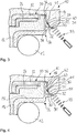
- FIG 1 an enlarged section of a bearing 10 for a support bearing, not shown, is shown, which is loaded by a spring 12, which can be part of a strut, not shown, in particular a McPherson strut, in order to rotate between a vehicle body, not shown, and the spring 12 enable.
- a spring 12 which can be part of a strut, not shown, in particular a McPherson strut, in order to rotate between a vehicle body, not shown, and the spring 12 enable.
- the bearing 10 has a first housing part 14 and a second housing part 16, between which a housing gap 18 is formed.
- the first housing part 14 is supported on a vehicle body (not shown), whereas the second housing part 16 is supported on the spring 12.
- the spring 12 instead of the spring 12 that can Connect the second housing part 16 to an air spring, not shown.
- the second housing part 16 can be part of a rolling piston of the air spring, for example.
- the two housing parts 14, 16 are made of a plastic, in particular a fiber-reinforced plastic.
- the bearing device 20 has a first sliding body 22 and a second sliding body 24, which slide against one another so that the two sliding bodies 22, 24 slide against one another when the two housing parts 14, 16 are rotated against one another.
- the two sliding bodies 22, 24 are positively, non-positively and / or cohesively connected to the respective housing part 14, 16.
- One of the sliding bodies 22, 24 can be made of plastic and the other sliding body 22, 24 can be made of metal or a hybrid material. Furthermore, both sliding bodies 22, 24 can be made of a plastic.
- a sealing system 26 is provided which seals the housing gap 18.
- the sealing system 28 is made of a thermoplastic elastomer or a vulcanized elastomer and can be connected to the second housing part 16 in a form-fitting, force-fitting and / or material-fitting manner.
- the second housing part 16 and the sealing system 26 are made of the same material with one another in the 2-component injection molding process.
- the sealing system 26 has a support section 28 for supporting the spring 12 and a first sealing lip 30 which is designed to be pivotable.
- the first sealing lip 30 is spaced apart from the first housing part 14 in the non-sealing state, the first sealing lip 30 protruding approximately horizontally from the second housing part 16 in the non-sealing state.
- the first sealing lip 30 has a contoured surface, in particular a beveled surface, on a side 32 facing away from the first housing part 14.
- a horizontally running first gap 31 is formed between the first sealing lip 30 and the first housing part 14.
- the length of the first gap 31 is at least 5 mm, the length of the distance from a free end of the first sealing lip 30 to the beginning of the housing gap 18 corresponds.
- the water particle mixture 33 If the water particle mixture 33 enters the housing gap 18, it can flow out of the housing gap 18 again as soon as the first sealing lip 30 has returned to the undeformed state, in particular swings back. This is the case when a water particle mixture 33 no longer strikes the first sealing lip 30.
- the sealing system 26 Since the first sealing lip 30 is spaced apart from the first housing part 14 in the non-sealing state, the sealing system 26 has a contactless function in the operating state, so that a lower breakaway torque is required for a relative rotation of the two housing parts 14, 16. At the same time, the sealing system 26 has a good sealing effect.
- FIG 2 a second embodiment of the bearing 10 is shown, which differs from the first embodiment in that the bearing device 20 has a ball bearing 34 instead of two sliding bodies 22, 24.
- the ball bearing 34 can be connected to the two housing parts 14, 16 in a form-fitting, force-fitting and / or material fit.
- FIG 3 a third embodiment of the bearing 10 and a second embodiment of the sealing system 26 is shown, which differ from the other embodiments in the design of the first housing part 14 and the sealing system 26 differ.
- the first housing part 14 has a recess 35 which faces the sealing system 26.
- the recess 35 is provided with a conical contact surface 37.
- the sealing system 26 shown has a contact section 36 which rests on the second housing part 16.
- a first chamber 38 adjoins the first sealing lip 30 in the region of the recess 35, which chamber is introduced into the sealing system 26 and is formed between the contact section 26 and the first housing part 14.
- the first chamber 38 causes a cross-sectional widening and thus ensures a reduction in pressure when the medium penetrates into the housing gap 18 via the first sealing lip 20.
- the first chamber 38 is designed in such a way that recirculation occurs in its interior and thus ensures a further reduction in pressure.
- the sealing system 26 has a second sealing lip 40 which is arranged within the recess 35.
- the second sealing lip 40 delimits the first chamber 38 and is arranged in series with the first sealing lip 30.
- the second sealing lip 40 is designed to be pivotable and is curved in the direction of the first sealing lip 30. In the non-sealing state, the second sealing lip 40 is spaced apart from the conical contact surface 37, a second gap 41 being formed between the second sealing lip 40 and the first housing part 14.
- the second sealing lip 40 is thus also contactless and can serve as a backup for the first sealing lip 30 if it should be damaged.
- the second sealing lip 40 pivots and bridges the second gap 41 until the second sealing lip 40 rests on the conical contact surface 37 and closes the housing gap 18. Since the second sealing lip 14 is spaced apart from the conical contact surface 37 in the non-sealing state and is arched in the direction of the first sealing lip 30, medium which has entered the second gap 41 or the housing gap 18 via the second sealing lip 40 can, due to gravity drain again.
- FIG 4 a fourth embodiment of the bearing 10 and a third embodiment of the sealing system 26 are shown, which differ from the third embodiment of the bearing 10 and the second embodiment of the sealing system 26 differ in the design of the housing gap 18 and the sealing system 26.
- the housing gap 18 formed between the two housing parts 14, 16 is wider in comparison to the other embodiments in order to create installation space for a second chamber 42 directly adjoining the second sealing lip 40.
- the second chamber 42 is introduced into the sealing system 26, in particular the contact section 36. Due to its cross-sectional expansion, the second chamber 42 ensures a renewed pressure reduction when the medium continues to enter the housing gap 18 via the second sealing lip 40.
- the second chamber 42 is shaped on a side facing away from the second sealing lip 40 in such a way that the medium entering is forced to recirculate in the direction of the second sealing lip 40 so that the medium can flow out of the housing gap 18 again.
- a fifth embodiment of the bearing 10 is shown, which differs from the fourth embodiment in that a labyrinth seal 44 is provided, which connects to the sealing system 26.
- the labyrinth seal 44 is formed from the two housing parts 14, 16, the first housing part 14 having a projection 46 which engages in a recess 48 formed on the second housing part 16.
Landscapes
- Engineering & Computer Science (AREA)
- General Engineering & Computer Science (AREA)
- Mechanical Engineering (AREA)
- Rolling Contact Bearings (AREA)
- Sealing Of Bearings (AREA)
- Sealing Devices (AREA)
- Sealing With Elastic Sealing Lips (AREA)
Description
- Die vorliegende Erfindung betrifft ein Lager für ein Stützlager, aufweisend ein erstes Gehäuseteil und ein zweites Gehäuseteil, zwischen denen ein Gehäusespalt ausgebildet ist, wobei in dem Gehäusespalt eine Lagereinrichtung angeordnet ist, wobei ein Dichtungssystem vorgesehen ist, das den Gehäusespalt abdichtet.
- Ein Lager der eingangs genannten Art kommt in einem Stützlager von gelenkten Achsen zum Einsatz, um eine Rotation zwischen einer Fahrzeugkarosserie und einer Feder, die Teil eines Federbeins, insbesondere eines McPherson-Federbeins, sein kann, zu ermöglichen.
- Das Lager ist dazu in einem Stützlager aufgenommen, das auch als "top mount" bezeichnet werden kann. Über das Stützlager werden die in die Feder beziehungsweise in einen Dämpfer eingeleiteten Kräfte in die Fahrzeugstruktur übertragen.
- Ein Lager der eingangs genannten Art kann auch in Luftfedern von Kraftfahrzeugen eingesetzt werden, um den Luftfederbalg vor Beschädigungen durch Torsion zu schützen, da aufgrund der Achskinematik selbst bei ungelenkten Achsen torsionale Bewegungen auftreten können.
- Für eine einwandfreie Funktion des Lagers ist es erforderlich, die Lagereinrichtung vor Verschmutzung zu schützen. Hierzu ist es bekannt, die Lagereinrichtung mittels eines Dichtungssystems abzudichten.
- Aus
US 2015/0367698 A1 geht ein Federbeinlager mit zwei Gehäuseteilen und einem zwischen den beiden Gehäuseteilen angeordneten Gleitlager hervor, wobei das Gleitlager durch eine aus beiden Gehäuseteilen gebildete Labyrinthdichtung abgedichtet ist. - Aus
US 9,261,134 B2 WO 2015/199022 A1 gehen Federbeinlager mit zwei Gehäuseteilen hervor, zwischen denen ein Gleitlager angeordnet ist, das mittels zweier Dichtlippen vor Medieneinflüssen abgedichtet ist. - Ferner geht aus
US 8 348 291 B1 ein Federbeinstützlager für ein Federbein hervor, das ein oberes Teil, welches relativ zur Fahrzeugkarosserie drehfest ist, und ein unteres Teil aufweist, das sich mit dem Achsschenkel dreht, wobei zwischen den beiden Teilen eine Labyrinthdichtung angeordnet ist. Zwischen einem Flansch des unteren Teils und einem Flansch einer Feder ist eine verschwenkbare Dichtung aus Elastomer eingeklemmt. - Darüber hinaus geht aus
FR 2 965 028 A1 - Der vorliegenden Erfindung liegt die Aufgabe zugrunde, ein Lager für ein Stützlager zu schaffen, das eine verbesserte Dichtung aufweist und kostengünstig herstellbar ist.
- Zur Lösung der Aufgabe wird ein Lager mit den Merkmalen des Anspruchs 1 vorgeschlagen.
- Vorteilhafte Ausgestaltungen des Lagers sind in den abhängigen Ansprüchen offenbart.
- Das erfindungsgemäße Lager für ein Stützlager, weist ein erstes Gehäuseteil und ein zweites Gehäuseteil auf, zwischen denen ein Gehäusespalt ausgebildet ist, wobei in dem Gehäusespalt eine Lagereinrichtung angeordnet ist, wobei ein Dichtungssystem vorgesehen ist, das den Gehäusespalt abdichtet, wobei das Dichtungssystem wenigstens eine erste Dichtlippe aufweist, die verschwenkbar ausgebildet ist, wobei die erste Dichtlippe im nicht-dichtenden Zustand von dem ersten Gehäuseteil und/oder dem zweiten Gehäuseteil beabstandet ist und zum Abdichten des Gehäusespaltes verschwenkt und an dem ersten Gehäuseteil und/oder dem zweiten Gehäuseteil anliegt, wobei das Dichtungssystem einen Auflageabschnitt zur Auflage eines Federelementes aufweist, der stoffeinheitlich in das Dichtungssystem integriert ist, wobei das Dichtungssystem formschlüssig und/oder stoffschlüssig mit dem ersten Gehäuseteil und/oder dem zweiten Gehäuseteil verbunden ist, und wobei das Dichtungssystem und das erste Gehäuseteil und/oder das zweite Gehäuseteil im 2-Komponenten-Spritzgußverfahren hergestellt sind.
- Das Lager wird vorzugsweise in einem Stützlager für ein Kraftfahrzeug eingesetzt. Unter einem Kraftfahrzeug wird vorliegend sowohl ein Personenkraftfahrzeug als auch ein Nutzfahrzeug verstanden. Das Lager kann in einem Stützlager für ein Federbein eingesetzt werden, um eine Rotation zwischen einer Fahrzeugkarosserie und einer Feder, die Bestandteil des Federbeins ist, zu ermöglichen. Ferner kann das Lager auch bei einer Luftfeder eingesetzt werden, um die auftretenden Torsionsbewegungen auszugleichen, die durch Vorspuränderungen an gelenkten und nicht gelenkten Achsen zum Beispiel während des Einfederns entstehen.
- Sobald ein äußerer Medienstrahl, wie beispielsweise ein Wasserpartikelgemisch, auf die erste Dichtlippe auftrifft, verschwenkt die erste Dichtlippe und liegt an dem ersten Gehäuseteil und/oder dem zweiten Gehäuseteil an und verschließt beziehungsweise dichtet den Gehäusespalt ab. Somit ist die Lagereinrichtung effektiv vor äußeren Medieneinflüssen und somit vor einer Verschmutzung geschützt. Da die erste Dichtlippe im nicht-dichtenden Zustand von dem ersten Gehäuseteil und/oder dem zweiten Gehäuseteil beabstandet ist, wird im Betriebszustand ein berührungsloses Dichtungssystem geschaffen, so dass für eine rotatorische Relativbewegung der beiden Gehäuseteile nur geringe Losbrechmomente und damit einhergehend geringe Drehmomente erforderlich sind. Darüber hinaus weist das Dichtungssystem im Betriebszustand eine gute Dichtungswirkung auf. Wenn kein Medienstrahl mehr auf die erste Dichtlippe auftrifft, verschwenkt die erste Dichtlippe wieder in ihren von dem ersten Gehäuseteil und/oder zweiten Gehäuseteil beabstandeten Zustand zurück, so dass in den Gehäusespalt eingetretenes Medium wieder aus dem Gehäusespalt abfließen kann. Da das Dichtungssystem zwischen den beiden Gehäuseteilen angeordnet ist, kann die Lagereinrichtung äußerst wirksam und gleichzeitig kostengünstig vor Medien- und Umwelteinflüssen geschützt werden.
- In einer vorteilhaften Ausgestaltung ist zwischen der wenigstens ersten Dichtlippe und dem ersten Gehäuseteil und/oder dem zweiten Gehäuseteil ein näherungsweise horizontal verlaufender erster Spalt ausgebildet. Vorteilhaft weist der erste Spalt eine Länge von mindestens 5 mm auf. Die Länge des näherungsweise horizontal verlaufenden ersten Spaltes entspricht der Entfernung von einem freien Ende der ersten Dichtlippe bis zu dem Beginn des Gehäusespaltes oder einer ersten Kammer. Dadurch wird für die Anlage der ersten Dichtlippe eine ausreichend flächige Abstützung geschaffen. Darüber hinaus muss ein eindringendes Medium, wie beispielsweise ein Fluid, zunächst eine gewisse Wegstrecke zurücklegen, bis es in den Gehäusespalt oder eine erste Kammer eindringt. Somit wird eine verbesserte Abdichtung geschaffen. Unter näherungsweise horizontal verlaufend wird vorliegend verstanden, dass der erste Spalt waagerecht verläuft, oder dass der erste Spalt in einem Winkel von gleich oder weniger als 5° zu einer Mittelachse des Lagers verläuft.
- In einer vorteilhaften Ausgestaltung ragt die erste Dichtlippe im nicht-dichtenden Zustand näherungsweise horizontal von dem ersten Gehäuseteil und/oder dem zweiten Gehäuseteil ab. Da die Dichtlippe im nicht-dichtenden Zustand von dem ersten Gehäuseteil und/oder dem zweiten Gehäuseteil abragt, wird ein berührungsloses Dichtungssystem geschaffen. Dadurch ist im unbelasteten, nicht-dichtenden Zustand für eine rotatorische Relativbewegung der beiden Gehäuseteile ein geringes Losbrechmoment erforderlich. Darüber hinaus kann die erste Dichtlippe durch ihre horizontale Anordnung beim Auftreffen eines Mediums verschwenken und damit den Gehäusespalt zum Abdichten verschließen. Im dichtenden Zustand arbeitet das Dichtungssystem ähnlich einem berührenden Dichtungssystem, bei dem die Dichtlippe an dem ersten Gehäuseteil und/oder dem zweiten Gehäuseteil anliegt. Unter näherungsweise horizontal abragend wird vorliegend verstanden, dass die erste Dichtlippe waagerecht von dem ersten Gehäuseteil und/oder zweiten Gehäuseteil abragt, oder dass die erste Dichtlippe einen Winkel von gleich oder weniger als 5° zu dem ersten Gehäuseteil und/oder dem zweiten Gehäuseteil einschließt.
- In einer vorteilhaften Ausgestaltung weist die erste Dichtlippe auf einer dem ersten Gehäuseteil und/oder dem zweiten Gehäuseteil abgewandten Seite eine konturierte Fläche auf. Dadurch kann die zum Verschwenken und Schließen des Gehäusespaltes erforderliche Kraft gezielt eingestellt werden. Die erste Dichtlippe kann auf einer dem ersten Gehäuseteil und/oder dem zweiten Gehäuseteil abgewandten Seite in Richtung ihres freien Endes spitz zulaufend ausgebildet.
- In einer vorteilhaften Ausgestaltung schließt sich an die erste Dichtlippe eine erste Kammer an. Die sich an die erste Dichtlippe anschließende erste Kammer sorgt für eine Querschnittsaufweitung, so dass der Druck bei einem Eintritt eines Mediums in den Gehäusespalt effektiv abgebaut werden kann. Vorteilhaft ist die Kammer derart ausgebildet, dass eine Rezirkulation in ihrem Inneren auftritt und so weiter Druck bei einem eintretenden Medium abgebaut werden kann. Die erste Kammer ist bevorzugt innerhalb des Gehäusespaltes angeordnet. Weiterhin vorteilhaft begrenzt die erste Dichtlippe die erste Kammer nach außen. Vorteilhaft ist die erste Kammer in das Dichtungssystem eingebracht. Weiterhin vorteilhaft kann die erste Kammer zwischen dem Dichtungssystem und dem ersten Gehäuseteil und/oder dem zweiten Gehäuseteil gebildet sein.
- In einer vorteilhaften Ausgestaltung weist das Dichtungssystem eine zweite Dichtlippe auf. Die zweite Dichtlippe bewirkt eine zusätzliche Abdichtung des Gehäusespaltes, wenn gegebenenfalls Medium in den Gehäusespalt eintritt, beispielsweise wenn die erste Dichtlippe beschädigt ist. Vorteilhaft ist die zweite Dichtlippe verschwenkbar ausgebildet, wobei die zweite Dichtlippe im nicht-dichtenden Zustand von dem ersten Gehäuseteil und/oder dem zweiten Gehäuseteil beabstandet ist und zum Abdichten des Gehäusespaltes verschwenkt und an dem ersten Gehäuseteil und/oder dem zweiten Gehäuseteil anliegt. Somit ist die zweite Dichtlippe als eine berührungslose Dichtung ausgebildet.
- In einer vorteilhaften Ausgestaltung sind die beiden Dichtlippen in Reihe angeordnet. Dadurch wird eine effektive Abdichtung des Gehäusespaltes geschaffen. Die zweite Dichtlippe wird erst dann aktiv, wenn Medium in den Gehäusespalt eintritt, beispielsweise wenn die erste Dichtlippe beschädigt ist.
- In einer vorteilhaften Ausgestaltung ist die zweite Dichtlippe innerhalb des Gehäusespaltes angeordnet, wobei zwischen der zweiten Dichtlippe und dem ersten Gehäuseteil und/oder dem zweiten Gehäuseteil ein zweiter Spalt ausgebildet ist. Dadurch ist die zweite Dichtlippe erst dann wirksam, wenn Medium in den Gehäusespalt eintritt, beispielsweise wenn die erste Dichtlippe beschädigt ist. Vorteilhaft ist der Verlauf des zweiten Spaltes zwischen zweiter Dichtlippe und dem Gehäuseteil aufsteigend nach oben gerichtet, so dass in diesen Gehäusespalt eintretendes Medium gegen die Schwerkraft aufsteigen muss und auch wieder nach unten abfließen kann.
- In einer vorteilhaften Ausgestaltung begrenzt die zweite Dichtlippe die erste Kammer. Wenn der Druck bei einem Medieneintritt in dem Gehäusespalt beziehungsweise in der ersten Kammer ansteigt, legt sich die zweite Dichtlippe an das erste Gehäuseteil und/oder das zweite Gehäuseteil an, in dem die zweite Dichtlippe verschwenkt und den Gehäusespalt beziehungsweise den zweiten Spalt verschließt und abdichtet. Vorteilhaft liegt die zweite Dichtlippe an einer konischen Anlagefläche des ersten Gehäuseteiles und/oder des zweiten Gehäuseteils an.
- In einer vorteilhaften Ausgestaltung ist die zweite Dichtlippe gewölbt. Insbesondere ist die zweite Dichtlippe in Richtung der ersten Dichtlippe gewölbt. Die Wölbung der zweiten Dichtlippe führt zu einer Rezirkulation eines eintretenden Mediums. Dies führt zu einem weiteren Druckabbau, so dass ein weiteres Eintreten des Mediums in den Gehäusespalt verhindert wird. Zudem bewirkt die in Richtung der ersten Dichtlippe gerichtete Wölbung, dass Medium, welches über die zweite Dichtlippe in den zweiten Spalt oder den Gehäusespalt eingetreten ist, aufgrund der Schwerkraft wieder aus dem zweiten Spalt oder dem Gehäusespalt abfließen kann.
- In einer vorteilhaften Ausgestaltung schließt sich an die zweite Dichtlippe eine zweite Kammer an. Die zweite Kammer bewirkt einen weiteren Druckabbau aufgrund seiner Querschnittsaufweitung, wenn Medium über die zweite Dichtlippe weiter in den Gehäusespalt eintritt. Vorteilhaft ist die zweite Kammer in das Dichtungssystem eingebracht. Weiterhin vorteilhaft kann die zweite Kammer zwischen dem Dichtungssystem und dem ersten Gehäuseteil und/oder dem zweiten Gehäuseteil gebildet sein. Bevorzugt ist die Kammer auf einer der zweiten Dichtlippe abgewandten Seite derart geformt, dass eintretendes Medium zur Rezirkulation aus dem Gehäusespalt gezwungen wird. Hierzu kann die zweite Kammer auf einer der zweiten Dichtlippe abgewandten Seite gekrümmt ausgebildet sein. Vorteilhaft ist die zweite Kammer oberhalb der zweiten Dichtlippe in der Art angeordnet, dass ein Medium, welches in diese Kammer vordringt, durch die Schwerkraft ungehindert wieder nach unten abfließen kann.
- Da das Dichtungssystem formschlüssig, und/oder stoffschlüssig mit dem ersten Gehäuseteil oder dem zweiten Gehäuseteil verbunden ist, wird auf einfache und kostengünstige Weise eine Verbindung zwischen dem Dichtungssystem und einem der Gehäuseteile oder beiden Gehäuseteilen geschaffen. Das Dichtungssystem kann mit dem ersten Gehäuseteil und/oder dem zweiten Gehäuseteil verpresst und/oder verklebt sein. Ferner kann das Dichtungssystem stoffschlüssig mit dem ersten Gehäuseteil und/oder dem zweiten Gehäuseteil verbunden sein. So können das Dichtungssystem und das erste Gehäuseteil und/oder das zweite Gehäuseteil im 2-Komponenten-Spritzgußverfahren hergestellt sein.
- Der Auflageabschnitt ist stoffeinheitlich in das Dichtungssystem integrierbar und damit kostengünstig herstellbar.
- In einer vorteilhaften Ausgestaltung weist die Lagereinrichtung wenigstens ein Gleitlager und/oder ein Wälzlager auf. Das Gleitlager kann einen Gleitkörper aus Metall aufweisen, der zwischen den beiden Gehäuseteilen angeordnet ist. Ferner kann das Gleitlager zwei Gleitkörper aufweisen, die zwischen den beiden Gehäuseteilen angeordnet sind. Beide Gleitkörper können aus Kunststoff sein. Ferner kann einer der Gleitkörper aus Kunststoff sein und der andere Gleitkörper kann aus Metall oder einem Hybridwerkstoff sein.
- In einer vorteilhaften Ausgestaltung ist zwischen den beiden Gehäuseteilen eine Labyrinthdichtung ausgebildet. Dadurch wird die Dichtwirkung nochmalig verbessert und Fett, welches sich im Gleit-oder Wälzlager befindet, wird am Fließen in den Gehäusespalt gehindert. Bevorzugt ist die Labyrinthdichtung dem Dichtungssystem nachgeschaltet. Vorteilhaft ist die Labyrinthdichtung aus den beiden Gehäuseteilen gebildet. So kann eines der Gehäuseteile einen Vorsprung aufweisen, der in einen in dem anderen Gehäuseteil ausgebildeten Rücksprung eingreift.
- In einer vorteilhaften Ausgestaltung sind die beiden Gehäuseteile aus einem Kunststoff, und das Dichtungssystem ist aus einem thermoplastischen Elastomer. Dadurch kann das Dichtungssystem stoffschlüssig mit dem ersten Gehäuseteil und/oder dem zweiten Gehäuseteil im 2-Komponenten-Spritzgussverfahren hergestellt werden. Wenn das Dichtungssystem einen Anlageabschnitt zur Anlage eines Federelementes aufweist, kann in das Dichtungssystem die elastomere Auflage des Federelementes stoffeinheitlich integriert sein. Vorteilhaft sind die beiden Gehäuseteile aus einem faserverstärkten Kunststoff, insbesondere aus Polyamid mit einem Glasfaseranteil von mehr als 30%. Die Gehäuseteile können ein Additiv aufweisen, das die Gleiteigenschaften verbessert. Darüber hinaus kann das Dichtungssystem aus einem vulkanisierten Elastomer sein.
- Nachfolgend werden das Lager, das Dichtungssystem sowie weitere Merkmale und Vorteile anhand von Ausführungsbeispielen näher erläutert, die in den Figuren schematisch dargestellt sind. Hierbei zeigen:
- Figur 1
- einen vergrößerten Ausschnitt eines Längsschnitts durch ein Lager gemäß einer ersten Ausführungsform und einem Dichtungssystem gemäß einer ersten Ausführungsform;
- Figur 2
- einen vergrößerten Ausschnitt eines Längsschnitts durch ein Lager gemäß einer zweiten Ausführungsform und einem Dichtungssystem gemäß einer ersten Ausführungsform;
- Figur 3
- einen vergrößerten Ausschnitt eines Längsschnitts durch ein Lager gemäß einer dritten Ausführungsform und einem Dichtungssystem gemäß einer zweiten Ausführungsform;
- Figur 4
- einen vergrößerten Ausschnitt eines Längsschnitts durch ein Lager gemäß einer vierten Ausführungsform und einem Dichtungssystem gemäß einer dritten Ausführungsform; und
- Figur 5
- einen vergrößerten Ausschnitt eines Längsschnitts durch ein Lager gemäß einer fünften Ausführungsform und einem Dichtungssystem gemäß einer dritten Ausführungsform.
- In
Figur 1 ist ein vergrößerter Ausschnitt eines Lagers 10 für ein nicht dargestelltes Stützlager gezeigt, welches durch eine Feder 12 belastet ist, die Teil eines nicht dargestellten Federbeins, insbesondere eines McPherson-Federbeins sein kann, um eine Rotation zwischen einer nicht dargestellten Fahrzeugkarosserie und der Feder 12 zu ermöglichen. - Das Lager 10 weist ein erstes Gehäuseteil 14 und ein zweites Gehäuseteil 16 auf, zwischen denen ein Gehäusespalt 18 ausgebildet ist. Innerhalb des Gehäusespalts 18 ist eine Lagereinrichtung 20 angeordnet, über die die beiden Gehäuseteile 14, 16 relativ zueinander verdrehbar sind. Das erste Gehäuseteil 14 stützt sich an einer nicht dargestellten Fahrzeugkarosserie ab, wohingegen sich das zweite Gehäuseteil 16 auf der Feder 12 abstützt. Statt der Feder 12 kann sich das zweite Gehäuseteil 16 an eine nicht dargestellte Luftfeder anschließen. In dem Fall kann das zweite Gehäuseteil 16 beispielsweise Teil eines Abrollkolbens der Luftfeder sein. Die beiden Gehäuseteile 14, 16 sind aus einem Kunststoff, insbesondere einem faserverstärkten Kunststoff.
- Die Lagereinrichtung 20 weist einen ersten Gleitkörper 22 und einen zweiten Gleitkörper 24 auf, die gleitend aneinander anliegen, so dass die beiden Gleitkörper 22, 24 gegeneinander gleiten, wenn die beiden Gehäuseteile 14, 16 gegeneinander verdreht werden. Die beiden Gleitkörper 22, 24 sind form-, kraft- und/oder stoffschlüssig mit dem jeweiligen Gehäuseteil 14, 16 verbunden. Einer der Gleitkörper 22, 24 kann aus Kunststoff und der andere Gleitkörper 22, 24 kann aus Metall oder einem Hybridwerkstoff sein. Ferner können beide Gleitkörper 22, 24 aus einem Kunststoff sein.
- Zur Abdichtung des Gehäusespalts 18 vor einem Eintritt eines Mediums, wie beispielsweise eines in
Fig. 1 dargestellten Wasserpartikelgemisches 33, ist ein Dichtungssystem 26 vorgesehen, das den Gehäusespalt 18 abdichtet. Das Dichtungssystem 28 ist aus einem thermoplastischen Elastomer oder einem vulkanisierten Elastomer und kann formschlüssig, kraftschlüssig und/oder stoffschlüssig mit dem zweiten Gehäuseteil 16 verbunden sein. Bevorzugt sind das zweite Gehäuseteil 16 und das Dichtungssystem 26 stoffeinheitlich miteinander im 2-Komponenten-Spritzgussverfahren hergestellt. - Das Dichtungssystem 26 weist einen Auflageabschnitt 28 zur Auflage der Feder 12 und eine erste Dichtlippe 30 auf, die verschwenkbar ausgebildet ist. Die erste Dichtlippe 30 ist im nicht-dichtenden Zustand von dem ersten Gehäuseteil 14 beabstandet, wobei die erste Dichtlippe 30 im nicht-dichtenden Zustand näherungsweise horizontal von dem zweiten Gehäuseteil 16 abragt. Die erste Dichtlippe 30 weist auf einer dem ersten Gehäuseteil 14 abgewandten Seite 32 eine konturierte Fläche, insbesondere eine abgeschrägte Fläche auf.
- Im nicht-dichten Zustand ist zwischen der ersten Dichtlippe 30 und dem ersten Gehäuseteil 14 ein horizontal verlaufender erster Spalt 31 ausgebildet. Die Länge des ersten Spaltes 31 beträgt mindestens 5 mm, wobei die Länge der Entfernung von einem freien Ende der ersten Dichtlippe 30 bis zu dem Beginn des Gehäusespaltes 18 entspricht.
- Beim Auftreffen eines Mediums, wie das in
Fig. 1 dargestellte Wasserpartikelgemisch 33, auf die erste Dichtlippe 30, verschwenkt die erste Dichtlippe 30 und überbrückt den ersten Spalt 31, bis die erste Dichtlippe 30 an dem ersten Gehäuseteil 14 anliegt und den Gehäusespalt 18 verschließt. Somit wird der Gehäusespalt 18 effektiv abgedichtet und ein Eintritt des Wasserpartikelgemisches 33 wird verhindert. - Sofern das Wasserpartikelgemisch 33 in den Gehäusespalt 18 eintritt, kann dieses wieder aus dem Gehäusespalt 18 herausfließen, sobald die erste Dichtlippe 30 wieder in den unverformten Zustand zurückgekehrt, insbesondere zurückschwenkt. Dies ist dann der Fall, wenn kein Wasserpartikelgemisch 33 mehr auf die erste Dichtlippe 30 auftrifft.
- Da die erste Dichtlippe 30 im nicht-dichtenden Zustand von dem ersten Gehäuseteil 14 beabstandet ist, weist das Dichtungssystem 26 im Betriebszustand eine berührungslose Funktion auf, so dass für eine Relativverdrehung der beiden Gehäuseteile 14, 16 ein geringeres Losbrechmoment erforderlich ist. Gleichzeitig weist das Dichtungssystem 26 eine gute Dichtungswirkung auf.
- Im Folgenden werden weitere Ausführungsformen für das Lager und das Dichtungssystem beschrieben, wobei für gleiche und funktionsgleiche Teile dieselben Bezugszeichen verwendet werden.
- In
Figur 2 ist eine zweite Ausführungsform des Lagers 10 gezeigt, die sich von der ersten Ausführungsform dadurch unterscheidet, dass die Lagereinrichtung 20 anstelle zweier Gleitkörper 22,24 ein Kugellager 34 aufweist. Das Kugellager 34 kann form-, kraft- und/oder stoffschlüssig mit den beiden Gehäuseteilen 14, 16 verbunden sein. - In
Figur 3 ist eine dritte Ausführungsform des Lagers 10 und eine zweite Ausführungsform des Dichtungssystems 26 gezeigt, die sich von den anderen Ausführungsformen in der Ausgestaltung des ersten Gehäuseteiles 14 und dem Dichtungssystem 26 unterscheiden. Das erste Gehäuseteil 14 weist eine Aussparung 35 auf, die dem Dichtungssystem 26 zugewandt ist. Die Aussparung 35 ist mit einer konischen Anlagefläche 37 versehen. - Das in
Fig. 3 dargestellte Dichtungssystem 26 weist einen Anlageabschnitt 36 auf, der an dem zweiten Gehäuseteil 16 anliegt. An die erste Dichtlippe 30 schließt sich im Bereich der Aussparung 35 eine erste Kammer 38 an, die in das Dichtungssystem 26 eingebracht und zwischen dem Anlageabschnitt 26 und dem ersten Gehäuseteil 14 gebildet ist. Die erste Kammer 38 bewirkt eine Querschnittsaufweitung und sorgt so für einen Druckabbau, wenn Medium über die erste Dichtlippe 20 in den Gehäusespalt 18 eindringt. Wie inFigur 3 ersichtlich ist, ist die erste Kammer 38 derart ausgebildet, dass eine Rezirkulation in ihrem Inneren auftritt und so für einen weiteren Druckabbau sorgt. - Wie zudem in
Figur 3 ersichtlich ist, weist das Dichtungssystem 26 eine zweite Dichtlippe 40 auf, die innerhalb der Aussparung 35 angeordnet ist. Die zweite Dichtlippe 40 begrenzt die erste Kammer 38 und ist in Reihe zu der ersten Dichtlippe 30 angeordnet. Die zweite Dichtlippe 40 ist verschwenkbar ausgebildet und ist in Richtung der ersten Dichtlippe 30 gewölbt. Im nicht-dichtenden Zustand ist die zweite Dichtlippe 40 von der konischen Anlagefläche 37 beabstandet, wobei zwischen der zweiten Dichtlippe 40 und dem ersten Gehäuseteil 14 ein zweiter Spalt 41 ausgebildet ist. Die zweite Dichtlippe 40 ist somit ebenfalls berührungslos und kann als Backup für die erste Dichtlippe 30 dienen, wenn diese beschädigt sein sollte. - Wenn der Druck in der ersten Kammer 28 ansteigt, verschwenkt die zweite Dichtlippe 40 und überbrückt den zweiten Spalt 41, bis die zweite Dichtlippe 40 an der konischen Anlagefläche 37 anliegt und den Gehäusespalt 18 verschließt. Da die zweite Dichtlippe 14 im nicht-dichtenden Zustand von der konischen Anlagefläche 37 beabstandet und in Richtung der ersten Dichtlippe 30 gewölbt ist, kann Medium, welches über die zweite Dichtlippe 40 in den zweiten Spalt 41 oder den Gehäusespalt 18 eingetreten ist, aufgrund der Schwerkraft wieder abfließen.
- In
Figur 4 ist eine vierte Ausführungsform des Lagers 10 und eine dritte Ausführungsform des Dichtungssystems 26 gezeigt, die sich von der dritten Ausführungsform des Lagers 10 und der zweiten Ausführungsform des Dichtungssystems 26 in der Ausgestaltung des Gehäusespaltes 18 und dem Dichtungssystem 26 unterscheiden. - Der zwischen den beiden Gehäuseteilen 14, 16 ausgebildete Gehäusespalt 18 ist im Vergleich zu den anderen Ausführungsformen breiter, um Bauraum für eine unmittelbar an die zweite Dichtlippe 40 anschließende zweite Kammer 42 zu schaffen. Die zweite Kammer 42 ist in das Dichtungssystem 26, insbesondere den Anlageabschnitt 36 eingebracht. Die zweite Kammer 42 sorgt aufgrund ihrer Querschnittsaufweitung für einen erneuten Druckabbau, wenn Medium über die zweite Dichtlippe 40 weiter in den Gehäusespalt 18 eintritt. Wie zudem in
Figur 4 ersichtlich ist, ist die zweite Kammer 42 auf einer der zweiten Dichtlippe 40 abgewandten Seite derart geformt, dass eintretendes Medium zur Rezirkulation in Richtung der zweiten Dichtlippe 40 gezwungen wird, so dass das Medium wieder aus dem Gehäusespalt 18 abfließen kann. - In
Figur 5 ist eine fünfte Ausführungsform des Lagers 10 gezeigt, die sich von der vierten Ausführungsform dadurch unterscheidet, dass eine Labyrinthdichtung 44 vorgesehen ist, die sich an das Dichtungssystem 26 anschließt. Die Labyrinthdichtung 44 ist aus den beiden Gehäuseteilen 14, 16 gebildet, wobei das erste Gehäuseteil 14 eine Vorsprung 46 aufweist, der in einem am zweiten Gehäuseteil 16 ausgebildeten Rücksprung 48 eingreift. -
- 10
- Lager
- 12
- Feder
- 14
- erstes Gehäuseteil
- 16
- zweites Gehäuseteil
- 18
- Gehäusespalt
- 20
- Lagereinrichtung
- 22
- erster Gleitkörper
- 24
- zweiter Gleitkörper
- 26
- Dichtungssystem
- 28
- Auflageabschnitt
- 30
- erste Dichtlippe
- 31
- erster Spalt
- 32
- abgewandte Seite
- 33
- Wasserpartikelgemisch
- 34
- Kugellager
- 35
- Aussparung
- 36
- Anlageabschnitt
- 37
- konische Anlagefläche
- 38
- erste Kammer
- 40
- zweite Dichtlippe
- 41
- zweiter Spalt
- 42
- zweite Kammer
- 44
- Labyrinthdichtung
- 46
- Vorsprung
- 48
- Rücksprung
Claims (13)
- Lager (10) für ein Stützlager, aufweisend ein erstes Gehäuseteil (14) und ein zweites Gehäuseteil (16), zwischen denen ein Gehäusespalt (18) ausgebildet ist, wobei in dem Gehäusespalt (18) eine Lagereinrichtung (20) angeordnet ist, wobei ein Dichtungssystem (26) vorgesehen ist, das den Gehäusespalt (18) abdichtet, wobei das Dichtungssystem (26) wenigstens eine erste Dichtlippe (30) aufweist, die verschwenkbar ausgebildet ist, wobei die erste Dichtlippe (30) im nicht-dichtenden Zustand von dem ersten Gehäuseteil (14) und/oder dem zweiten Gehäuseteil (16) beabstandet ist und zum Abdichten des Gehäusespaltes (18) verschwenkt und an dem ersten Gehäuseteil (14) und/oder dem zweiten Gehäuseteil (16) anliegt, wobei das Dichtungssystem (26) einen Auflageabschnitt (28) zur Auflage eines Federelementes aufweist, dadurch gekennzeichnet, dass der Auflageabschnitt stoffeinheitlich in das Dichtungssystem integriert ist, wobei das Dichtungssystem (26) formschlüssig und/oder stoffschlüssig mit dem ersten Gehäuseteil (14) und/oder dem zweiten Gehäuseteil (16) verbunden ist, und wobei das Dichtungssystem (26) und das erste Gehäuseteil (14) und/oder das zweite Gehäuseteil (16) im 2-Komponenten-Spritzgußverfahren hergestellt sind.
- Lager (10) nach Anspruch 1, dadurch gekennzeichnet, dass zwischen der wenigstens ersten Dichtlippe (30) und dem ersten Gehäuseteil (14) und/oder dem zweiten Gehäuseteil (16) ein näherungsweise horizontal verlaufender erster Spalt (31) ausgebildet ist.
- Lager (10) nach Anspruch 1 oder 2, dadurch gekennzeichnet, dass die erste Dichtlippe (30) im nicht-dichtenden Zustand näherungsweise horizontal von dem ersten Gehäuseteil (14) und/oder dem zweiten Gehäuseteil (16) abragt.
- Lager (10) nach einem der vorhergehenden Ansprüche, dadurch gekennzeichnet, dass sich an die erste Dichtlippe (30) eine erste Kammer (38) anschließt.
- Lager (10) nach einem der vorhergehenden Ansprüchen, dadurch gekennzeichnet, dass das Dichtungssystem (26) eine zweite Dichtlippe (40) aufweist.
- Lager (10) nach Anspruch 5, dadurch gekennzeichnet, dass die beiden Dichtlippen (30, 40) in Reihe angeordnet sind.
- Lager (10) nach Anspruch 5 oder 6, dadurch gekennzeichnet, dass die zweite Dichtlippe (40) innerhalb des Gehäusespaltes (18) angeordnet ist, wobei zwischen der zweiten Dichtlippe (40) und dem ersten Gehäuseteil (14) und/oder dem zweiten Gehäuseteil (16) ein zweiter Spalt (41) ausgebildet ist.
- Lager (10) nach einem der Ansprüche 5 bis 7, dadurch gekennzeichnet, dass die zweite Dichtlippe (40) die erste Kammer (38) begrenzt.
- Lager (10) nach einem der Ansprüche 5 bis 8, dadurch gekennzeichnet, dass die zweite Dichtlippe (40) gewölbt ist.
- Lager (10) nach einem der Ansprüche 5 bis 9, dadurch gekennzeichnet, dass sich an die zweite Dichtlippe (40) eine zweite Kammer (42) anschließt.
- Lager (10) nach einem der vorhergehenden Ansprüche, dadurch gekennzeichnet, dass die Lagereinrichtung (20) wenigstens ein Gleitlager und/oder ein Wälzlager aufweist.
- Lager (10) nach einem der vorhergehenden Ansprüche, dadurch gekennzeichnet, dass zwischen den beiden Gehäuseteilen (14, 16) eine Labyrinthdichtung (44) ausgebildet ist.
- Lager (10) nach einem der vorhergehenden Ansprüche, dadurch gekennzeichnet, dass die beiden Gehäuseteile (14, 16) aus einem Kunststoff sind, und dass das Dichtungssystem (26) aus einem thermoplastischen Elastomer ist.
Applications Claiming Priority (2)
| Application Number | Priority Date | Filing Date | Title |
|---|---|---|---|
| DE102017107135.0A DE102017107135A1 (de) | 2017-04-03 | 2017-04-03 | Lager für ein Stützlager |
| PCT/EP2018/058173 WO2018185006A1 (de) | 2017-04-03 | 2018-03-29 | Lager für ein stützlager |
Publications (2)
| Publication Number | Publication Date |
|---|---|
| EP3607219A1 EP3607219A1 (de) | 2020-02-12 |
| EP3607219B1 true EP3607219B1 (de) | 2020-09-30 |
Family
ID=61952662
Family Applications (1)
| Application Number | Title | Priority Date | Filing Date |
|---|---|---|---|
| EP18716955.2A Active EP3607219B1 (de) | 2017-04-03 | 2018-03-29 | Lager für ein stützlager |
Country Status (5)
| Country | Link |
|---|---|
| US (1) | US11339825B2 (de) |
| EP (1) | EP3607219B1 (de) |
| CN (1) | CN110366644A (de) |
| DE (1) | DE102017107135A1 (de) |
| WO (1) | WO2018185006A1 (de) |
Families Citing this family (5)
| Publication number | Priority date | Publication date | Assignee | Title |
|---|---|---|---|---|
| DE102018102745B4 (de) * | 2018-02-07 | 2020-07-09 | Vibracoustic Gmbh | Lagerungssystem zur elastischen Lagerung eines Federbeins oder eines Schwingungsdämpfers sowie ein Federbein oder ein Schwingungsdämpfer |
| DE202019106036U1 (de) * | 2019-10-30 | 2019-12-02 | Vibracoustic Ag | Lagerstrukturbauteil |
| FR3106082B1 (fr) * | 2020-01-10 | 2022-02-18 | Ntn Snr Roulements | Butée de suspension de véhicule automobile |
| DE102020200586A1 (de) | 2020-01-20 | 2021-07-22 | Aktiebolaget Skf | Aufhängungsaxiallagervorrichtung |
| DE202020104632U1 (de) | 2020-08-11 | 2021-11-15 | Rollax Gmbh & Co. Kg | Federbeinlager |
Family Cites Families (25)
| Publication number | Priority date | Publication date | Assignee | Title |
|---|---|---|---|---|
| US3940153A (en) | 1974-12-09 | 1976-02-24 | General Motors Corporation | Labyrinth seal |
| JP3521483B2 (ja) * | 1994-06-03 | 2004-04-19 | 日本精工株式会社 | ストラット用密封型スラスト軸受 |
| DE10056175A1 (de) * | 1999-11-17 | 2001-06-13 | Ntn Toyo Bearing Co Ltd | Wheel Bearing and Sealing Davice Therefor |
| FR2829429B1 (fr) * | 2001-09-12 | 2003-12-12 | Skf Ab | Dispositif de butee de suspension |
| US7909333B2 (en) * | 2007-01-12 | 2011-03-22 | Federal-Mogul Worldwide, Inc. | Unitized seal assembly having soft retention and debris expulsion features |
| FR2928187B1 (fr) | 2008-02-28 | 2010-04-02 | Skf Ab | Dispositif de butee de suspension et jambe de force |
| FR2934656B1 (fr) * | 2008-08-01 | 2013-05-17 | Skf Ab | Dispositif de butee de suspension et jambe de force. |
| FR2948066B1 (fr) * | 2009-07-17 | 2012-01-20 | Skf Ab | Dispositif de butee de suspension et jambe de force. |
| WO2011120563A1 (en) | 2010-03-30 | 2011-10-06 | Aktiebolaget Skf | Axial thrust bearing device with a mobile sealing ring |
| JP5516210B2 (ja) | 2010-08-06 | 2014-06-11 | オイレス工業株式会社 | スラスト滑り軸受 |
| FR2965028B1 (fr) | 2010-09-20 | 2012-10-12 | Skf Ab | Dispositif de butee de suspension |
| DE102011004334A1 (de) * | 2011-02-17 | 2012-08-23 | Schaeffler Technologies Gmbh & Co. Kg | Federbeinlager |
| US8348291B1 (en) * | 2011-08-09 | 2013-01-08 | GM Global Technology Operations LLC | Suspension strut bearing deflector seal |
| CN103089804A (zh) * | 2011-11-02 | 2013-05-08 | Skf公司 | 悬架止推轴承装置 |
| US8992094B2 (en) * | 2012-07-18 | 2015-03-31 | Schaeffler Technologies AG & Co. KG | Suspension strut bearing |
| US9140365B1 (en) * | 2012-09-11 | 2015-09-22 | Engineered Seal Products, Inc. | Outer seal |
| DE102013201965A1 (de) | 2013-02-07 | 2014-08-07 | Schaeffler Technologies Gmbh & Co. Kg | Federbeinlager |
| CN104663496B (zh) * | 2013-11-29 | 2017-08-01 | 赵国强 | 可快速调整的动物颈圈 |
| JP6519483B2 (ja) * | 2013-12-16 | 2019-05-29 | 日本精工株式会社 | レリーズ軸受及びクラッチレリーズ軸受装置 |
| JP6326657B2 (ja) | 2014-06-26 | 2018-05-23 | オイレス工業株式会社 | スラスト滑り軸受 |
| US10030777B2 (en) * | 2016-04-11 | 2018-07-24 | Prippell Technologies, Llc | Dynamic fluid seal |
| US10473222B2 (en) * | 2016-04-11 | 2019-11-12 | Prippell Technologies, Llc | Dynamic fluid seal |
| JP6439758B2 (ja) * | 2016-07-25 | 2018-12-19 | 株式会社ジェイテクト | 密封型スラスト玉軸受 |
| US10948017B2 (en) * | 2016-12-21 | 2021-03-16 | Nok Corporation | Sealing device |
| US10598219B2 (en) * | 2017-09-18 | 2020-03-24 | Roller Bearing Company Of America, Inc. | Bearing and sealing arrangement for joints in heavy duty vehicles |
-
2017
- 2017-04-03 DE DE102017107135.0A patent/DE102017107135A1/de not_active Withdrawn
-
2018
- 2018-03-29 US US16/499,959 patent/US11339825B2/en active Active
- 2018-03-29 WO PCT/EP2018/058173 patent/WO2018185006A1/de not_active Ceased
- 2018-03-29 CN CN201880014538.4A patent/CN110366644A/zh active Pending
- 2018-03-29 EP EP18716955.2A patent/EP3607219B1/de active Active
Non-Patent Citations (1)
| Title |
|---|
| None * |
Also Published As
| Publication number | Publication date |
|---|---|
| CN110366644A (zh) | 2019-10-22 |
| US11339825B2 (en) | 2022-05-24 |
| EP3607219A1 (de) | 2020-02-12 |
| DE102017107135A1 (de) | 2018-10-04 |
| US20210131489A1 (en) | 2021-05-06 |
| WO2018185006A1 (de) | 2018-10-11 |
Similar Documents
| Publication | Publication Date | Title |
|---|---|---|
| EP3607219B1 (de) | Lager für ein stützlager | |
| DE102018105175B4 (de) | Fahrzeugaufhängungsbuchsenanordnung und Verfahren zu deren Montage | |
| DE3346665C2 (de) | ||
| EP0485696B1 (de) | Elastisches Gleitlager | |
| EP0487891A1 (de) | Elastisches Gleitlager | |
| EP3445980A1 (de) | Axialkugelgelenk und längeneinstellbarer zweipunktlenker mit einem solchen axialkugelgelenk | |
| DE102013006432A1 (de) | Doppelwellfeder mit dämpfender Zwischenschicht | |
| EP2886896A2 (de) | Wälzlager mit Dichtungseinheit für Wälzlager | |
| DE19832956C2 (de) | Gummigelagertes Kugelgelenk mit spannungsoptimierter Lagergeometrie | |
| DE102016218792A1 (de) | Axiallager sowie Achsschenkel-Lageranordnung und deren Verwendung | |
| WO2003031834A1 (de) | Kugelgelenk | |
| DE102017200008A1 (de) | Getriebeeinheit für ein Kraftfahrzeug | |
| EP1502022A1 (de) | Kraftstoffverteilungsrohr für kraftfahrzeug-einspritzeinrichtungen, insbesondere für common-rail-systeme | |
| DE112020001119T5 (de) | Halterungsbaugruppe und verfahren zur herstellung einer halterungsbaugruppe | |
| DE10311851B4 (de) | Schwenklagerung | |
| EP1225355B1 (de) | Dichtungssystem für ein Lager eines Kreuzgelenkes | |
| DE10344804B4 (de) | Schwenklagerung | |
| DE102008039280A1 (de) | Achsschenkelbolzenlagerung und Verfahren zur Montage einer solchen | |
| DE102020134593A1 (de) | Hydraulische Buchse mit Abstützstellen und Verfahren zur Herstellung einer solchen Buchse | |
| DE102019006967A1 (de) | Elastomerlager | |
| EP1964694B1 (de) | Gelenk- und/oder Lageranordnung, insbesondere Hülsengelenk zur Anbindung von Radführungselementen eines Fahrzeugs, sowie Verfahren zur Herstellung einer Gelenk- und/oder Lageranordnung | |
| DE102011004496A1 (de) | Kugelgelenk mit Innenabdichtung | |
| DE102008024621B4 (de) | Kreuzgelenk für eine Lenksäule eines Kraftfahrzeuges | |
| DE102007031321A1 (de) | Dichtungsanordnung an einer Achsschenkelbolzenlagerung sowie Verfahren zu deren Montage | |
| EP2331836A1 (de) | Kreuzgelenk, insbesondere für eine lenksäule für ein kraftfahrzeug |
Legal Events
| Date | Code | Title | Description |
|---|---|---|---|
| STAA | Information on the status of an ep patent application or granted ep patent |
Free format text: STATUS: UNKNOWN |
|
| STAA | Information on the status of an ep patent application or granted ep patent |
Free format text: STATUS: THE INTERNATIONAL PUBLICATION HAS BEEN MADE |
|
| PUAI | Public reference made under article 153(3) epc to a published international application that has entered the european phase |
Free format text: ORIGINAL CODE: 0009012 |
|
| STAA | Information on the status of an ep patent application or granted ep patent |
Free format text: STATUS: REQUEST FOR EXAMINATION WAS MADE |
|
| 17P | Request for examination filed |
Effective date: 20191030 |
|
| AK | Designated contracting states |
Kind code of ref document: A1 Designated state(s): AL AT BE BG CH CY CZ DE DK EE ES FI FR GB GR HR HU IE IS IT LI LT LU LV MC MK MT NL NO PL PT RO RS SE SI SK SM TR |
|
| AX | Request for extension of the european patent |
Extension state: BA ME |
|
| GRAP | Despatch of communication of intention to grant a patent |
Free format text: ORIGINAL CODE: EPIDOSNIGR1 |
|
| STAA | Information on the status of an ep patent application or granted ep patent |
Free format text: STATUS: GRANT OF PATENT IS INTENDED |
|
| DAV | Request for validation of the european patent (deleted) | ||
| DAX | Request for extension of the european patent (deleted) | ||
| INTG | Intention to grant announced |
Effective date: 20200706 |
|
| RAP1 | Party data changed (applicant data changed or rights of an application transferred) |
Owner name: VIBRACOUSTIC AG |
|
| GRAS | Grant fee paid |
Free format text: ORIGINAL CODE: EPIDOSNIGR3 |
|
| GRAA | (expected) grant |
Free format text: ORIGINAL CODE: 0009210 |
|
| STAA | Information on the status of an ep patent application or granted ep patent |
Free format text: STATUS: THE PATENT HAS BEEN GRANTED |
|
| AK | Designated contracting states |
Kind code of ref document: B1 Designated state(s): AL AT BE BG CH CY CZ DE DK EE ES FI FR GB GR HR HU IE IS IT LI LT LU LV MC MK MT NL NO PL PT RO RS SE SI SK SM TR |
|
| REG | Reference to a national code |
Ref country code: CH Ref legal event code: EP Ref country code: GB Ref legal event code: FG4D Free format text: NOT ENGLISH |
|
| REG | Reference to a national code |
Ref country code: AT Ref legal event code: REF Ref document number: 1319091 Country of ref document: AT Kind code of ref document: T Effective date: 20201015 |
|
| REG | Reference to a national code |
Ref country code: DE Ref legal event code: R096 Ref document number: 502018002620 Country of ref document: DE |
|
| REG | Reference to a national code |
Ref country code: IE Ref legal event code: FG4D Free format text: LANGUAGE OF EP DOCUMENT: GERMAN |
|
| PG25 | Lapsed in a contracting state [announced via postgrant information from national office to epo] |
Ref country code: FI Free format text: LAPSE BECAUSE OF FAILURE TO SUBMIT A TRANSLATION OF THE DESCRIPTION OR TO PAY THE FEE WITHIN THE PRESCRIBED TIME-LIMIT Effective date: 20200930 Ref country code: HR Free format text: LAPSE BECAUSE OF FAILURE TO SUBMIT A TRANSLATION OF THE DESCRIPTION OR TO PAY THE FEE WITHIN THE PRESCRIBED TIME-LIMIT Effective date: 20200930 Ref country code: SE Free format text: LAPSE BECAUSE OF FAILURE TO SUBMIT A TRANSLATION OF THE DESCRIPTION OR TO PAY THE FEE WITHIN THE PRESCRIBED TIME-LIMIT Effective date: 20200930 Ref country code: NO Free format text: LAPSE BECAUSE OF FAILURE TO SUBMIT A TRANSLATION OF THE DESCRIPTION OR TO PAY THE FEE WITHIN THE PRESCRIBED TIME-LIMIT Effective date: 20201230 Ref country code: GR Free format text: LAPSE BECAUSE OF FAILURE TO SUBMIT A TRANSLATION OF THE DESCRIPTION OR TO PAY THE FEE WITHIN THE PRESCRIBED TIME-LIMIT Effective date: 20201231 Ref country code: BG Free format text: LAPSE BECAUSE OF FAILURE TO SUBMIT A TRANSLATION OF THE DESCRIPTION OR TO PAY THE FEE WITHIN THE PRESCRIBED TIME-LIMIT Effective date: 20201230 |
|
| PG25 | Lapsed in a contracting state [announced via postgrant information from national office to epo] |
Ref country code: RS Free format text: LAPSE BECAUSE OF FAILURE TO SUBMIT A TRANSLATION OF THE DESCRIPTION OR TO PAY THE FEE WITHIN THE PRESCRIBED TIME-LIMIT Effective date: 20200930 Ref country code: LV Free format text: LAPSE BECAUSE OF FAILURE TO SUBMIT A TRANSLATION OF THE DESCRIPTION OR TO PAY THE FEE WITHIN THE PRESCRIBED TIME-LIMIT Effective date: 20200930 |
|
| REG | Reference to a national code |
Ref country code: NL Ref legal event code: MP Effective date: 20200930 |
|
| REG | Reference to a national code |
Ref country code: LT Ref legal event code: MG4D |
|
| PG25 | Lapsed in a contracting state [announced via postgrant information from national office to epo] |
Ref country code: PT Free format text: LAPSE BECAUSE OF FAILURE TO SUBMIT A TRANSLATION OF THE DESCRIPTION OR TO PAY THE FEE WITHIN THE PRESCRIBED TIME-LIMIT Effective date: 20210201 Ref country code: RO Free format text: LAPSE BECAUSE OF FAILURE TO SUBMIT A TRANSLATION OF THE DESCRIPTION OR TO PAY THE FEE WITHIN THE PRESCRIBED TIME-LIMIT Effective date: 20200930 Ref country code: CZ Free format text: LAPSE BECAUSE OF FAILURE TO SUBMIT A TRANSLATION OF THE DESCRIPTION OR TO PAY THE FEE WITHIN THE PRESCRIBED TIME-LIMIT Effective date: 20200930 Ref country code: EE Free format text: LAPSE BECAUSE OF FAILURE TO SUBMIT A TRANSLATION OF THE DESCRIPTION OR TO PAY THE FEE WITHIN THE PRESCRIBED TIME-LIMIT Effective date: 20200930 Ref country code: LT Free format text: LAPSE BECAUSE OF FAILURE TO SUBMIT A TRANSLATION OF THE DESCRIPTION OR TO PAY THE FEE WITHIN THE PRESCRIBED TIME-LIMIT Effective date: 20200930 Ref country code: SM Free format text: LAPSE BECAUSE OF FAILURE TO SUBMIT A TRANSLATION OF THE DESCRIPTION OR TO PAY THE FEE WITHIN THE PRESCRIBED TIME-LIMIT Effective date: 20200930 |
|
| PG25 | Lapsed in a contracting state [announced via postgrant information from national office to epo] |
Ref country code: IS Free format text: LAPSE BECAUSE OF FAILURE TO SUBMIT A TRANSLATION OF THE DESCRIPTION OR TO PAY THE FEE WITHIN THE PRESCRIBED TIME-LIMIT Effective date: 20210130 Ref country code: PL Free format text: LAPSE BECAUSE OF FAILURE TO SUBMIT A TRANSLATION OF THE DESCRIPTION OR TO PAY THE FEE WITHIN THE PRESCRIBED TIME-LIMIT Effective date: 20200930 Ref country code: AL Free format text: LAPSE BECAUSE OF FAILURE TO SUBMIT A TRANSLATION OF THE DESCRIPTION OR TO PAY THE FEE WITHIN THE PRESCRIBED TIME-LIMIT Effective date: 20200930 Ref country code: ES Free format text: LAPSE BECAUSE OF FAILURE TO SUBMIT A TRANSLATION OF THE DESCRIPTION OR TO PAY THE FEE WITHIN THE PRESCRIBED TIME-LIMIT Effective date: 20200930 |
|
| PG25 | Lapsed in a contracting state [announced via postgrant information from national office to epo] |
Ref country code: NL Free format text: LAPSE BECAUSE OF FAILURE TO SUBMIT A TRANSLATION OF THE DESCRIPTION OR TO PAY THE FEE WITHIN THE PRESCRIBED TIME-LIMIT Effective date: 20200930 Ref country code: SK Free format text: LAPSE BECAUSE OF FAILURE TO SUBMIT A TRANSLATION OF THE DESCRIPTION OR TO PAY THE FEE WITHIN THE PRESCRIBED TIME-LIMIT Effective date: 20200930 |
|
| REG | Reference to a national code |
Ref country code: DE Ref legal event code: R097 Ref document number: 502018002620 Country of ref document: DE |
|
| REG | Reference to a national code |
Ref country code: DE Ref legal event code: R082 Ref document number: 502018002620 Country of ref document: DE Representative=s name: PATENTANWAELTE OLBRICHT, BUCHHOLD, KEULERTZ PA, DE Ref country code: DE Ref legal event code: R081 Ref document number: 502018002620 Country of ref document: DE Owner name: VIBRACOUSTIC SE, DE Free format text: FORMER OWNER: VIBRACOUSTIC AG, 64293 DARMSTADT, DE |
|
| PLBE | No opposition filed within time limit |
Free format text: ORIGINAL CODE: 0009261 |
|
| STAA | Information on the status of an ep patent application or granted ep patent |
Free format text: STATUS: NO OPPOSITION FILED WITHIN TIME LIMIT |
|
| PG25 | Lapsed in a contracting state [announced via postgrant information from national office to epo] |
Ref country code: DK Free format text: LAPSE BECAUSE OF FAILURE TO SUBMIT A TRANSLATION OF THE DESCRIPTION OR TO PAY THE FEE WITHIN THE PRESCRIBED TIME-LIMIT Effective date: 20200930 |
|
| 26N | No opposition filed |
Effective date: 20210701 |
|
| PG25 | Lapsed in a contracting state [announced via postgrant information from national office to epo] |
Ref country code: IT Free format text: LAPSE BECAUSE OF FAILURE TO SUBMIT A TRANSLATION OF THE DESCRIPTION OR TO PAY THE FEE WITHIN THE PRESCRIBED TIME-LIMIT Effective date: 20200930 Ref country code: MC Free format text: LAPSE BECAUSE OF FAILURE TO SUBMIT A TRANSLATION OF THE DESCRIPTION OR TO PAY THE FEE WITHIN THE PRESCRIBED TIME-LIMIT Effective date: 20200930 |
|
| REG | Reference to a national code |
Ref country code: CH Ref legal event code: PL |
|
| PG25 | Lapsed in a contracting state [announced via postgrant information from national office to epo] |
Ref country code: SI Free format text: LAPSE BECAUSE OF FAILURE TO SUBMIT A TRANSLATION OF THE DESCRIPTION OR TO PAY THE FEE WITHIN THE PRESCRIBED TIME-LIMIT Effective date: 20200930 |
|
| REG | Reference to a national code |
Ref country code: BE Ref legal event code: MM Effective date: 20210331 |
|
| PG25 | Lapsed in a contracting state [announced via postgrant information from national office to epo] |
Ref country code: IE Free format text: LAPSE BECAUSE OF NON-PAYMENT OF DUE FEES Effective date: 20210329 Ref country code: LU Free format text: LAPSE BECAUSE OF NON-PAYMENT OF DUE FEES Effective date: 20210329 Ref country code: LI Free format text: LAPSE BECAUSE OF NON-PAYMENT OF DUE FEES Effective date: 20210331 Ref country code: CH Free format text: LAPSE BECAUSE OF NON-PAYMENT OF DUE FEES Effective date: 20210331 |
|
| PG25 | Lapsed in a contracting state [announced via postgrant information from national office to epo] |
Ref country code: IS Free format text: LAPSE BECAUSE OF FAILURE TO SUBMIT A TRANSLATION OF THE DESCRIPTION OR TO PAY THE FEE WITHIN THE PRESCRIBED TIME-LIMIT Effective date: 20210130 |
|
| PG25 | Lapsed in a contracting state [announced via postgrant information from national office to epo] |
Ref country code: BE Free format text: LAPSE BECAUSE OF NON-PAYMENT OF DUE FEES Effective date: 20210331 |
|
| PG25 | Lapsed in a contracting state [announced via postgrant information from national office to epo] |
Ref country code: CY Free format text: LAPSE BECAUSE OF FAILURE TO SUBMIT A TRANSLATION OF THE DESCRIPTION OR TO PAY THE FEE WITHIN THE PRESCRIBED TIME-LIMIT Effective date: 20200930 |
|
| PG25 | Lapsed in a contracting state [announced via postgrant information from national office to epo] |
Ref country code: HU Free format text: LAPSE BECAUSE OF FAILURE TO SUBMIT A TRANSLATION OF THE DESCRIPTION OR TO PAY THE FEE WITHIN THE PRESCRIBED TIME-LIMIT; INVALID AB INITIO Effective date: 20180329 |
|
| PG25 | Lapsed in a contracting state [announced via postgrant information from national office to epo] |
Ref country code: MK Free format text: LAPSE BECAUSE OF FAILURE TO SUBMIT A TRANSLATION OF THE DESCRIPTION OR TO PAY THE FEE WITHIN THE PRESCRIBED TIME-LIMIT Effective date: 20200930 |
|
| REG | Reference to a national code |
Ref country code: AT Ref legal event code: MM01 Ref document number: 1319091 Country of ref document: AT Kind code of ref document: T Effective date: 20230329 |
|
| PG25 | Lapsed in a contracting state [announced via postgrant information from national office to epo] |
Ref country code: AT Free format text: LAPSE BECAUSE OF NON-PAYMENT OF DUE FEES Effective date: 20230329 |
|
| PG25 | Lapsed in a contracting state [announced via postgrant information from national office to epo] |
Ref country code: AT Free format text: LAPSE BECAUSE OF NON-PAYMENT OF DUE FEES Effective date: 20230329 |
|
| PG25 | Lapsed in a contracting state [announced via postgrant information from national office to epo] |
Ref country code: MT Free format text: LAPSE BECAUSE OF FAILURE TO SUBMIT A TRANSLATION OF THE DESCRIPTION OR TO PAY THE FEE WITHIN THE PRESCRIBED TIME-LIMIT Effective date: 20200930 |
|
| PG25 | Lapsed in a contracting state [announced via postgrant information from national office to epo] |
Ref country code: TR Free format text: LAPSE BECAUSE OF FAILURE TO SUBMIT A TRANSLATION OF THE DESCRIPTION OR TO PAY THE FEE WITHIN THE PRESCRIBED TIME-LIMIT Effective date: 20200930 |
|
| PGFP | Annual fee paid to national office [announced via postgrant information from national office to epo] |
Ref country code: GB Payment date: 20260330 Year of fee payment: 9 |
|
| PGFP | Annual fee paid to national office [announced via postgrant information from national office to epo] |
Ref country code: DE Payment date: 20260331 Year of fee payment: 9 |
|
| PGFP | Annual fee paid to national office [announced via postgrant information from national office to epo] |
Ref country code: AT Payment date: 20260410 Year of fee payment: 5 |
|
| PGFP | Annual fee paid to national office [announced via postgrant information from national office to epo] |
Ref country code: FR Payment date: 20260330 Year of fee payment: 9 |