EP3606172B1 - Informationsverarbeitungsverfahren und zugehöriges produkt - Google Patents
Informationsverarbeitungsverfahren und zugehöriges produkt Download PDFInfo
- Publication number
- EP3606172B1 EP3606172B1 EP17912533.1A EP17912533A EP3606172B1 EP 3606172 B1 EP3606172 B1 EP 3606172B1 EP 17912533 A EP17912533 A EP 17912533A EP 3606172 B1 EP3606172 B1 EP 3606172B1
- Authority
- EP
- European Patent Office
- Prior art keywords
- mapping relationship
- user equipment
- beams
- network equipment
- information
- Prior art date
- Legal status (The legal status is an assumption and is not a legal conclusion. Google has not performed a legal analysis and makes no representation as to the accuracy of the status listed.)
- Active
Links
- 230000010365 information processing Effects 0.000 title claims description 9
- 238000003672 processing method Methods 0.000 title 1
- 238000013507 mapping Methods 0.000 claims description 85
- 238000000034 method Methods 0.000 claims description 44
- 230000015654 memory Effects 0.000 claims description 25
- 230000011664 signaling Effects 0.000 claims description 19
- 238000012935 Averaging Methods 0.000 claims description 3
- 238000004590 computer program Methods 0.000 description 29
- 238000004891 communication Methods 0.000 description 18
- 238000012545 processing Methods 0.000 description 18
- 230000006870 function Effects 0.000 description 14
- 238000010586 diagram Methods 0.000 description 10
- 238000007726 management method Methods 0.000 description 5
- 238000005259 measurement Methods 0.000 description 4
- 238000013500 data storage Methods 0.000 description 3
- 238000005516 engineering process Methods 0.000 description 3
- 238000009795 derivation Methods 0.000 description 2
- 238000010295 mobile communication Methods 0.000 description 2
- 239000007787 solid Substances 0.000 description 2
- 230000005236 sound signal Effects 0.000 description 2
- 230000001133 acceleration Effects 0.000 description 1
- 230000009286 beneficial effect Effects 0.000 description 1
- 230000005540 biological transmission Effects 0.000 description 1
- 230000001413 cellular effect Effects 0.000 description 1
- 238000006243 chemical reaction Methods 0.000 description 1
- 230000001419 dependent effect Effects 0.000 description 1
- 238000007599 discharging Methods 0.000 description 1
- 239000000835 fiber Substances 0.000 description 1
- 230000005484 gravity Effects 0.000 description 1
- 230000003993 interaction Effects 0.000 description 1
- 230000002452 interceptive effect Effects 0.000 description 1
- 239000004973 liquid crystal related substance Substances 0.000 description 1
- 230000007774 longterm Effects 0.000 description 1
- 230000003287 optical effect Effects 0.000 description 1
- 238000010079 rubber tapping Methods 0.000 description 1
- 239000004065 semiconductor Substances 0.000 description 1
Images


Classifications
-
- H—ELECTRICITY
- H04—ELECTRIC COMMUNICATION TECHNIQUE
- H04W—WIRELESS COMMUNICATION NETWORKS
- H04W48/00—Access restriction; Network selection; Access point selection
- H04W48/08—Access restriction or access information delivery, e.g. discovery data delivery
- H04W48/12—Access restriction or access information delivery, e.g. discovery data delivery using downlink control channel
-
- H—ELECTRICITY
- H04—ELECTRIC COMMUNICATION TECHNIQUE
- H04B—TRANSMISSION
- H04B7/00—Radio transmission systems, i.e. using radiation field
- H04B7/02—Diversity systems; Multi-antenna system, i.e. transmission or reception using multiple antennas
- H04B7/04—Diversity systems; Multi-antenna system, i.e. transmission or reception using multiple antennas using two or more spaced independent antennas
- H04B7/0408—Diversity systems; Multi-antenna system, i.e. transmission or reception using multiple antennas using two or more spaced independent antennas using two or more beams, i.e. beam diversity
-
- H—ELECTRICITY
- H04—ELECTRIC COMMUNICATION TECHNIQUE
- H04W—WIRELESS COMMUNICATION NETWORKS
- H04W72/00—Local resource management
- H04W72/04—Wireless resource allocation
- H04W72/044—Wireless resource allocation based on the type of the allocated resource
- H04W72/046—Wireless resource allocation based on the type of the allocated resource the resource being in the space domain, e.g. beams
-
- H—ELECTRICITY
- H04—ELECTRIC COMMUNICATION TECHNIQUE
- H04B—TRANSMISSION
- H04B17/00—Monitoring; Testing
- H04B17/30—Monitoring; Testing of propagation channels
- H04B17/309—Measuring or estimating channel quality parameters
-
- H—ELECTRICITY
- H04—ELECTRIC COMMUNICATION TECHNIQUE
- H04L—TRANSMISSION OF DIGITAL INFORMATION, e.g. TELEGRAPHIC COMMUNICATION
- H04L5/00—Arrangements affording multiple use of the transmission path
- H04L5/003—Arrangements for allocating sub-channels of the transmission path
- H04L5/0058—Allocation criteria
- H04L5/0076—Allocation utility-based
-
- H—ELECTRICITY
- H04—ELECTRIC COMMUNICATION TECHNIQUE
- H04L—TRANSMISSION OF DIGITAL INFORMATION, e.g. TELEGRAPHIC COMMUNICATION
- H04L5/00—Arrangements affording multiple use of the transmission path
- H04L5/0091—Signaling for the administration of the divided path
- H04L5/0096—Indication of changes in allocation
-
- H—ELECTRICITY
- H04—ELECTRIC COMMUNICATION TECHNIQUE
- H04W—WIRELESS COMMUNICATION NETWORKS
- H04W16/00—Network planning, e.g. coverage or traffic planning tools; Network deployment, e.g. resource partitioning or cells structures
- H04W16/24—Cell structures
- H04W16/28—Cell structures using beam steering
-
- H—ELECTRICITY
- H04—ELECTRIC COMMUNICATION TECHNIQUE
- H04W—WIRELESS COMMUNICATION NETWORKS
- H04W24/00—Supervisory, monitoring or testing arrangements
- H04W24/10—Scheduling measurement reports ; Arrangements for measurement reports
-
- H—ELECTRICITY
- H04—ELECTRIC COMMUNICATION TECHNIQUE
- H04W—WIRELESS COMMUNICATION NETWORKS
- H04W36/00—Hand-off or reselection arrangements
- H04W36/0005—Control or signalling for completing the hand-off
- H04W36/0083—Determination of parameters used for hand-off, e.g. generation or modification of neighbour cell lists
- H04W36/0085—Hand-off measurements
- H04W36/0094—Definition of hand-off measurement parameters
-
- H—ELECTRICITY
- H04—ELECTRIC COMMUNICATION TECHNIQUE
- H04W—WIRELESS COMMUNICATION NETWORKS
- H04W40/00—Communication routing or communication path finding
- H04W40/02—Communication route or path selection, e.g. power-based or shortest path routing
- H04W40/12—Communication route or path selection, e.g. power-based or shortest path routing based on transmission quality or channel quality
-
- H—ELECTRICITY
- H04—ELECTRIC COMMUNICATION TECHNIQUE
- H04W—WIRELESS COMMUNICATION NETWORKS
- H04W56/00—Synchronisation arrangements
- H04W56/001—Synchronization between nodes
-
- H—ELECTRICITY
- H04—ELECTRIC COMMUNICATION TECHNIQUE
- H04W—WIRELESS COMMUNICATION NETWORKS
- H04W72/00—Local resource management
- H04W72/12—Wireless traffic scheduling
- H04W72/1263—Mapping of traffic onto schedule, e.g. scheduled allocation or multiplexing of flows
-
- H—ELECTRICITY
- H04—ELECTRIC COMMUNICATION TECHNIQUE
- H04W—WIRELESS COMMUNICATION NETWORKS
- H04W72/00—Local resource management
- H04W72/20—Control channels or signalling for resource management
- H04W72/23—Control channels or signalling for resource management in the downlink direction of a wireless link, i.e. towards a terminal
-
- H—ELECTRICITY
- H04—ELECTRIC COMMUNICATION TECHNIQUE
- H04W—WIRELESS COMMUNICATION NETWORKS
- H04W72/00—Local resource management
- H04W72/50—Allocation or scheduling criteria for wireless resources
- H04W72/54—Allocation or scheduling criteria for wireless resources based on quality criteria
- H04W72/542—Allocation or scheduling criteria for wireless resources based on quality criteria using measured or perceived quality
-
- H—ELECTRICITY
- H04—ELECTRIC COMMUNICATION TECHNIQUE
- H04W—WIRELESS COMMUNICATION NETWORKS
- H04W8/00—Network data management
- H04W8/22—Processing or transfer of terminal data, e.g. status or physical capabilities
-
- H—ELECTRICITY
- H04—ELECTRIC COMMUNICATION TECHNIQUE
- H04W—WIRELESS COMMUNICATION NETWORKS
- H04W84/00—Network topologies
- H04W84/02—Hierarchically pre-organised networks, e.g. paging networks, cellular networks, WLAN [Wireless Local Area Network] or WLL [Wireless Local Loop]
-
- H—ELECTRICITY
- H04—ELECTRIC COMMUNICATION TECHNIQUE
- H04W—WIRELESS COMMUNICATION NETWORKS
- H04W88/00—Devices specially adapted for wireless communication networks, e.g. terminals, base stations or access point devices
- H04W88/02—Terminal devices
-
- H—ELECTRICITY
- H04—ELECTRIC COMMUNICATION TECHNIQUE
- H04W—WIRELESS COMMUNICATION NETWORKS
- H04W88/00—Devices specially adapted for wireless communication networks, e.g. terminals, base stations or access point devices
- H04W88/08—Access point devices
-
- H—ELECTRICITY
- H04—ELECTRIC COMMUNICATION TECHNIQUE
- H04W—WIRELESS COMMUNICATION NETWORKS
- H04W92/00—Interfaces specially adapted for wireless communication networks
- H04W92/02—Inter-networking arrangements
-
- H—ELECTRICITY
- H04—ELECTRIC COMMUNICATION TECHNIQUE
- H04W—WIRELESS COMMUNICATION NETWORKS
- H04W92/00—Interfaces specially adapted for wireless communication networks
- H04W92/04—Interfaces between hierarchically different network devices
- H04W92/10—Interfaces between hierarchically different network devices between terminal device and access point, i.e. wireless air interface
Definitions
- the present invention relates to the field of communication technologies, and in particular, to a method and related product for information processing.
- 5G 5-Generation
- NR New Radio
- the UE may distinguish not only a cell which it resides in or services, but also a beam which it resides in or services.
- a numeral number N of beams to be measured is configured for the UE through the network.
- obtaining a cell quality requires the UE to average the N beams, and the qualities of the N beams are all greater than a threshold.
- the number of beams to be measured cannot be uniformly configured for all cells. Therefore, determining the number of beams which need to be measured is a technical problem that needs to be solved.
- CMCC "On the Number of Beams to Derive Cell Quality", 3GPP DRAFT; R2-1705793, retrieved from the Internet, discloses that different values of N could also be configured to cells working on the same carrier frequency, by including a list of cell specific values of N or the mapping information between beam number and corresponding value of N in measurement configuration.
- SAMSUNG "RRM Measurement in NR: The Details of Cell Quality Derivation", 3GPP DRAFT;R2-1703722, retrieved from the Internet, discloses the details of cell quality derivation.
- an embodiment of the present invention provides a method for information processing, comprising:
- an embodiment of the present invention provides a method for information processing, comprising: sending, by a network equipment, a configured mapping relationship between N and M which is used to determine the N, wherein the N is a number of beams which need to be measured, and the M is a number of beams actually supported by the network equipment.
- an embodiment of the present invention provides a user equipment, comprising a processing unit, wherein the processing unit is configured to obtain a mapping relationship between N and M, wherein the N is a maximum number of beams for obtaining a cell quality, and the M is a number of beams actually sent by the network equipment; the N is determined based on the mapping relationship between the N and the M, and/or the M.
- an embodiment of the present invention provides a network equipment, comprising a communication unit and a processing unit, wherein the processing unit is configured to send, by using the communication unit, a configured mapping relationship between N and M, wherein the N is a number of beams to be measured, and the M is a number of beams actually supported by the network equipment, wherein the mapping relationship between the N and the M is used to determine the N.
- an embodiment of the present invention provides a user equipment, comprising one or more processors, one or more memories, one or more transceivers, and one or more programs; wherein the one or more programs are stored in the memory and configured to be executed by the one or more processors; wherein the program comprises instructions for performing steps in the method as described in the first aspect of the embodiments of the present invention.
- an embodiment of the present invention provides a network equipment, comprising one or more processors, one or more memories, one or more transceivers, and one or more programs; wherein the one or more programs are stored in the memory and configured to be executed by the one or more processors; wherein the program comprises instructions for performing steps in the method in the second aspect of the embodiments of the present invention.
- an embodiment of the present invention provides a computer readable storage medium, the computer readable storage medium stores a computer program for exchanging electronic data, and the computer program causes a computer to perform the method of the first aspect of the embodiments of the present invention.
- an embodiment of the present invention provides a computer readable storage medium, the computer readable storage medium stores a computer program for exchanging electronic data, and the computer program causes a computer to perform the method of the second aspect of the embodiments of the present invention.
- an embodiment of the present invention provides a computer program product, the computer program product comprises a non-transitory computer readable storage medium storing a computer program, and the computer program may be operated to cause a computer to perform the method of the first aspect of the embodiments of the present invention.
- an embodiment of the present invention provides a computer program product, the computer program product comprises a non-transitory computer readable storage medium storing a computer program, and the computer program may be operated to cause a computer to perform the method of the second aspect of the embodiments of the present invention.
- a mapping relationship between N and M is pre-configured, the N is a maximum number of beams to obtain a cell quality, and the M is a number of beams actually sent by a network equipment.
- a user equipment may determine the value of N based on the mapping relationship and/or the M and further solves the problem that the value of N cannot be uniformly configured.
- references to "an embodiment” herein mean that a particular feature, structure, or characteristic described with reference to the embodiments may be included in at least one embodiment of the present application.
- the appearances of this phrase in various places in the specification do not necessarily refer to the same embodiments, and are not exclusive or alternative embodiments that are mutually exclusive with other embodiments.
- Those skilled in the art will understand and implicitly understand that the embodiments described herein may be combined with other embodiments.
- FIG. 1 is a schematic diagram of a network architecture according to an embodiment of the present application.
- the network architecture shown in FIG. 1 comprises a user equipment 110 and a network equipment 120.
- the network equipment 120 may be a network equipment of a serving cell, or a network equipment of a neighboring cell.
- a numeral number N of beams to be measured is configured for the user equipment through the network. Due to the difference in the number of beams between cells in different frequency bands and even different cells in a same frequency band, the number of beams to be measured cannot be uniformly configured for all cells.
- the easiest way to configure the number N of beams to be measured is: since a serving cell knows the number of all the beams in the cell, the N value of the cell may be directly configured by the serving cell; however, for a neighboring cell, the neighboring cell needs to inform the N value to be configured or the number of beams supported by the neighboring cell to the serving cell, and the serving cell configures the N value based on the interactive information.
- a problem existing in configuring the N value of the neighboring cell is that if the N value of the neighboring cell is configured by the serving cell, the serving cell and the neighboring cell are required to perform information interaction, or the serving cell obtains configuration information of the neighboring cell through configuration of network management in advance. Since there is no interface between the serving cell and the neighboring cell, this configuration mode is not applicable.
- a mapping relationship between N and M is pre-configured, the N is a maximum number of beams to obtain a cell quality, and the M is a numeral number of beams actually sent by a network equipment. Then, a user equipment may obtain the value of N based on the mapping relationship and/or the M and further solves the problem that the value of N cannot be uniformly configured.
- the mapping relationship between the N and the M obtained by the user equipment is configured for the user equipment 110 by the network equipment 120 of the serving cell, or is pre-defined in the protocol, etc.
- a User Equipment is an equipment that provides voice and/or data connectivity to a user, for example, a handheld device with a wireless connection function, an in-vehicle device, and the like.
- a common User Equipment includes, for example, a mobile phone, a tablet, a notebook computer, a PDA, a Mobile Internet Device (MID) and a wearable device, such as a smart watch, a smart bracelet, a pedometer, and the like.
- the network equipment refers to a node equipment on the network side.
- the network equipment may be a Radio Access Network (RAN) device on the access network side of a cellular network
- the so-called RAN device is a device that connects a user equipment to a wireless network, including but not limited to: an evolved Node B (eNB), a Radio Network Controller (RNC), a Node B (NB), a Base Station Controller (BSC), a Base Transceiver Station (BTS), a Home Base Station (for example, Home evolved NodeB, or Home Node B, HNB), a Baseband Unit (BBU), and a Mobility Management Entity (MME);
- the network equipment may also be a node device in a Wireless Local Area Network (WLAN), such as an Access Controller (AC), a gateway, or a WIFI Access Point (AP).
- WLAN Wireless Local Area Network
- AC Access Controller
- AP WIFI Access Point
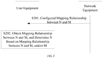
- FIG. 2 is a schematic flowchart of a method for information processing according to an embodiment of the present invention, including the following steps:
- the above mapping relationship between the N and the M is a table, and the table records the N value corresponding to each M value, as shown in Table 1.
- Table 1 M N 10 5 11 5 12 5 13 6 14 6 15 7 ⁇ ⁇
- the above mapping relationship between the N and the M is a table, and the table records the value of N corresponding to each range of M values, as shown in Table 2.
- Table 2 M N 1 ⁇ 10 5 11 ⁇ 20 10 21 ⁇ 33 15 34 ⁇ 50 22 ⁇ ⁇
- each X is equal to 0.5.
- each Y is equal to 0.5.
- each Z is equal to 2.
- mapping relationships between N and M there are a plurality of mapping relationships between N and M, and each mapping relationship between the N and the M corresponds to at least one period.
- the period corresponding to the mapping relationship between the N and the M is configured by the network equipment, or the period corresponding to the mapping relationship the N and the M is pre-agreed.
- mapping relationship 1 corresponds to period 1 and period 2
- mapping relationship 2 corresponds to period 3
- mapping relationship 3 corresponds to period 4.
- the period 1, the period 2, the period 3, and the period 4 do not intersect each other.
- a plurality of the mapping relationships between the N and the M may be configured based on the periods, and a user equipment may flexibly select a more suitable mapping relationship based on time, thereby determining the N value more flexibly.
- mapping relationship between the N and the M is configured by the network equipment for the user equipment
- specific content described above is equally applicable in the case that the mapping relationship between the N and the M is pre-defined in the protocol, which will not be described herein.
- some specific embodiments described below are applicable not only when the mapping relationship between the N and the M is configured for the user equipment by the network equipment, but also when the mapping relationship between the N and the M is pre-defined in the protocol, which will not be described herein.
- the method further comprises: The user equipment measures, after determining the N, a cell beam and averages at most N beams to obtain a cell quality where the network equipment is, and the at most N beams are beams that meet a threshold of beam quality.
- the threshold of foregoing beam quality may be configured by a network equipment, or may be pre-defined in the protocol, and the like.
- the beam meets the threshold of beam quality, that is, the beam quality is greater than or equal to the threshold of beam quality.
- the user equipment averages 8 of the 10 beams to obtain the cell quality which is equal to (Sbeam1+Sbeam2+...+Sbeam8)/8.
- the cell quality obtained by averaging the at most 10 beams by the user equipment is equal to (Sbeam1+Sbeam2+...+Sbeam10)/10.
- a mapping relationship between N and M is pre-configured, the N is a maximum number of beams to obtain a cell quality, and the M is a number of beams actually sent by a network equipment.
- a user equipment may determine the value of N based on the mapping relationship and/or the M and further solves the problem that the value of N cannot be uniformly configured.
- a network equipment sends broadcast information or a dedicated signaling, and the broadcast information or the dedicated signaling comprises the mapping relationship between the N and the M; a user equipment receives the broadcast information or the dedicated signaling from the network equipment to obtain the mapping relationship between the N and the M.
- the dedicated signaling comprises a RRC Reconfiguration signaling.
- Using a dedicated signaling to send a mapping relationship between N and M may save signaling overhead.
- mapping relationship between the N and the M may be sent to the user equipment by introducing a specific Information Element (IE) in the dedicated signaling.
- IE Information Element
- the method further comprises:
- the system information includes Common Resource Configuration information.
- the information which the user equipment must know in cell access includes the system information.
- the network equipment provides the M to the user equipment through the system information, which may save a scheduling signaling, and may also enable the user equipment to obtain the value of the M in cell access.
- the method further comprises:
- the network equipment since measuring the cell beam quality is for performing cell search, and the purpose of cell search is to ensure that the user equipment obtains time synchronization and frequency synchronization of the system, so that the user equipment saves synchronization information during the process of cell search.
- the network equipment provides the M to the user equipment through the synchronization information, which may save a scheduling signaling, and may also enable the user equipment to obtain the value of M at the beginning.
- the network equipment may directly configure the at least two types of information for the user equipment.
- the network equipment directly configures the at least two types of information for the user equipment through broadcast information or the dedicated signaling.
- the network equipment may separately configure the at least two types of information for the user equipment.
- the network equipment configures some of the at least two types of information for the user equipment through broadcast information, and then configures the remaining information of the at least two types of information for the user equipment through the dedicated signaling.
- FIG. 3 is a user equipment 300 according to an embodiment of the present invention, comprising: one or more processors, one or more memories, one or more transceivers, and one or more programs.
- the one or more programs are stored in the memory and configured to be executed by the one or more processors.
- the program comprises instructions for performing the following steps:
- the program in terms of obtaining the mapping relationship between the N and the M, the program is specifically used to execute instructions of the following step: receiving broadcast information or a dedicated signaling from the network equipment.
- the broadcast information or the dedicated signaling comprises the mapping relationship between the N and the M.
- the program is further used to execute instructions of the following step: receiving system information from the network equipment.
- the M is included in the system information.
- the program is further used to execute instructions of the following step: receiving synchronization information from the network equipment.
- the M is included in the synchronization information.
- the program is further used to execute instructions of the following step:
- the user equipment measures, after determining the N, a cell beam and averages at most N beams to obtain a cell quality where the network equipment is, and the at most N beams are beams that meet a threshold of beam quality.
- each of the mapping relationship between the N and the M corresponds to at least one period when there are a plurality of mapping relationships between the N and the M, and the period corresponding to the mapping relationship between the N and the M is configured by the network equipment.
- a mapping relationship between N and M is pre-configured, the N is a maximum number of beams to obtain a cell quality, and the M is a number of beams actually sent by a network equipment.
- a user equipment may determine the value of N based on the mapping relationship and further solves the problem that the value of N cannot be uniformly configured.
- FIG. 4 is a network equipment 400 according to an embodiment of the present invention, comprising: one or more processors, one or more memories, one or more transceivers, and one or more programs.
- the one or more programs are stored in the memory and configured to be executed by the one or more processors.
- the program comprises instructions for performing the following step: sending a mapping relationship between N and M.
- the N is a number of beams which need to be measured
- the M is a number of beams actually supported by the network equipment
- the mapping relationship between the N and the M is used to determine the N.
- the program in terms of sending configuration of a mapping relationship between N and M, the program is specifically used to execute instructions of the following step: sending broadcast information or a dedicated signaling.
- the broadcast information or the dedicated signaling comprises the mapping relationship between the N and the M.
- the program is further used to execute instructions of the following step: sending system information, which the M is included in.
- the program is further used to execute instructions of the following step: sending synchronization information, which the M is included in.
- each of the mapping relationship between the N and the M corresponds to at least one period when there are a plurality of mapping relationships between the N and the M, and the period corresponding to the mapping relationship between the N and the M is configured by the network equipment.
- a mapping relationship between N and M is pre-configured, the N is a maximum number of beams to obtain a cell quality, and the M is a number of beams actually sent by a network equipment.
- a user equipment may determine the value of N based on the mapping relationship and further solves the problem that the value of N cannot be uniformly configured.
- FIG. 5 is a schematic structural diagram of a user equipment 500 according to this embodiment.
- the user equipment 500 comprises a processing unit 501, a communication unit 502, and a storage unit 503:
- the processing unit 501 is configured to obtain a mapping relationship between N and M, the N is a maximum number of beams for obtaining a cell quality, and the M is a number of beams actually sent by the network equipment; the N is determined based on the mapping relationship between the N and the M.
- the processing unit 501 may be a processor or a controller (For example, it may be a Central Processing Unit (CPU), a general-purpose processor, a Digital Signal Processor (DSP), an Application- Specific Integrated Circuit (ASIC), a Field Programmable Gate Array (FPGA), or other programmable logic device, transistor logic device, hardware component, or any combination thereof. It may be a logical block or a module or a circuit that can implement or carry out various illustrative examples described in the present invention.
- the processor may also be a combination of computing functions, for example, including one or more microprocessor combinations, a combination of a DSP, a microprocessor, and the like).
- the communication unit 502 may be a transceiver, a transceiver circuit, a radio frequency chip, a communication interface, etc.
- the storage unit 503 may be a memory.
- the processing unit 501 is a processor
- the communication unit 502 is a communication interface
- the storage unit 503 is a memory
- the user equipment involved in the embodiments of the present invention may be the user equipment shown in FIG. 3 .
- FIG. 6 is a schematic structural diagram of a network equipment 600 according to the present embodiment.
- the network equipment 600 comprises a processing unit 601, a communication unit 602 and a storage unit 603.
- the processing unit 601 is configured to send, by using the communication unit 602, a configured mapping relationship between N and M, the N is a number of beams to be measured, the M is a number of beams actually supported by the network equipment, and the mapping relationship between the N and the M is used to determine the N.
- the processing unit 601 may be a processor or a controller (For example, it may be a Central Processing Unit (CPU), a general-purpose processor, a Digital Signal Processor (DSP), an Application- Specific Integrated Circuit (ASIC), a Field Programmable Gate Array (FPGA), or other programmable logic device, transistor logic device, hardware component, or any combination thereof. It may be a logical block or a module or a circuit that can implement or carry out various illustrative examples described in the present invention.
- the processor may also be a combination of computing functions, for example, including one or more microprocessor combinations, a combination of a DSP, a microprocessor, and the like).
- the communication unit 602 may be a transceiver, a transceiver circuit, a radio frequency chip, a communication interface, etc.
- the storage unit 603 may be a memory.
- the network equipment involved in the embodiments of the present invention may be the network equipment shown in FIG. 4 .
- the user equipment may be any user equipment including a mobile phone, a tablet computer, a PDA (Personal Digital Assistant), a POS (Point of Sales), a car computer and so on, and take that the user equipment is a mobile phone as an example:
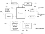
- FIG. 7 is a block diagram of a partial structure of a mobile phone related to a user equipment provided by an embodiment of the present invention.
- the mobile phone comprises components: a Radio Frequency (RF) circuit 910, a memory 920, an input unit 930, a display unit 940, a sensor 950, an audio circuit 960, a Wireless Fidelity (WiFi) module 970, a processor 980, a power supply 990 and so on.
- RF Radio Frequency
- the mobile phone may comprise more or less components than those illustrated, or some components may be combined, or different components may be arranged.
- the RF circuit 910 may be used for receiving and sending information.
- the RF circuit 910 comprises, but is not limited to, an antenna, at least one amplifier, a transceiver, a coupler, a Low Noise Amplifier (LNA), a duplexer, and the like.
- the RF circuit 910 may also communicate with the network and other equipments via wireless communication.
- the above wireless communication may use any communication standard or protocol, including but not limited to Global System of Mobile communication (GSM), General Packet Radio Service (GPRS), Code Division Multiple Access (CDMA), Wideband Code Division Multiple Access (WCDMA), Long Term Evolution (LTE), E-mail, Short Messaging Service (SMS), and the like.
- GSM Global System of Mobile communication
- GPRS General Packet Radio Service
- CDMA Code Division Multiple Access
- WCDMA Wideband Code Division Multiple Access
- LTE Long Term Evolution
- E-mail Short Messaging Service
- the memory 920 may be used to store software programs and modules, and the processor 980 executes various functional applications and data processing of the mobile phone by running software programs and modules stored in the memory 920.
- the memory 920 may mainly include a program storage area and a data storage area.
- the program storage area may store an operating system, an application required for at least one function, and the like.
- the data storage area may store data created based on usage of the mobile phone and so on.
- the memory 920 may comprise high-speed random access memory, and may also comprise a non-volatile memory, such as at least one magnetic disk storage device, flash memory device, or other volatile solid state storage device.
- the input unit 930 may be configured to receive input numeric or character information and to generate key signal input related to user setting and function control of the mobile phone.
- the input unit 930 may include a fingerprint identification module 931 and other input device 932.
- the fingerprint identification module 931 may collect fingerprint data of the user.
- the input unit 930 may also include other input device 932.
- other input device 932 may include, but is not limited to, one or more of a touch screen, a physical keyboard, a function key (such as a volume control button, a switch button), a trackball, a mouse, a joystick, and the like.
- the display unit 940 may be used to display information input by the user or information provided to the user as well as various menus of the mobile phone.
- the display unit 940 may include a display screen 941.
- the display screen 941 may be configured in the form of a Liquid Crystal Display (LCD), an Organic Light-Emitting Diode (OLED), or the like.
- LCD Liquid Crystal Display
- OLED Organic Light-Emitting Diode
- the fingerprint recognition module 931 and the display screen 941 implement the input and output functions of the mobile phone as two separate components in FIG. 7
- the fingerprint recognition module 931 and the display screen 941 may be integrated to implement the input and playing functions of the mobile phone in some embodiments.
- the mobile phone may also include at least one type of sensor 950, such as a light sensor, a motion sensor, and other sensors.
- the light sensor may include an ambient light sensor and a proximity sensor.
- the ambient light sensor may adjust the brightness of the display screen 941 based on the brightness of the ambient light, and the proximity sensor may turn off the display screen 941 and/or back light when the mobile phone moves to the ear.
- an accelerometer sensor can detect the magnitude of acceleration in all directions (usually three axes).
- the mobile phone When it is stationary, it can detect the magnitude and direction of gravity and it can be used for applications which identify the gesture of the mobile phone (such as horizontal and vertical screen switching, related games, magnetometer attitude calibration), vibration recognition related functions (such as pedometer, tapping), etc.; other sensors, which can also be configured on the mobile phone, such as a gyroscope, a barometer, a hygrometer, a thermometer and an infrared sensor, will not be described herein.
- other sensors which can also be configured on the mobile phone, such as a gyroscope, a barometer, a hygrometer, a thermometer and an infrared sensor, will not be described herein.
- An audio circuit 960, a speaker 961, and a microphone 962 may provide an audio interface between the user and the mobile phone.
- the audio circuit 960 may send a converted electrical signal of the received audio data to the speaker 961 for conversion to the sound signal by the speaker 961; on the other hand, the microphone 962 converts the collected sound signal into an electrical signal, then the audio circuit 960 converted the received electrical signal into audio data, and then the audio data, after processed by the processor 980, is sent to another mobile phone via the RF circuit 910, or is stored in the memory 920 for further processing.
- WiFi is a short-range wireless transmission technology
- the mobile phone may help users to send and receive emails, browse web pages, and access streaming media through the WiFi module 970, which provides users with wireless broadband internet access.
- FIG. 7 shows the WiFi module 970, it can be understood that it does not belong to the essential configuration of the mobile phone, and can be omitted as needed within the scope of not changing the essence of the invention.
- the processor 980 is the control center of the mobile phone, which connects various parts of the entire mobile phone via various interfaces and lines. By running or executing software programs and/or modules stored in the memory 920, invoking data stored in the memory 920, and executing various functions and data processing of the mobile phone, the mobile phone is overall monitored.
- the processor 980 may comprise one or more processing units.
- the processor 980 may integrate an application processor and a modem processor.
- the application processor mainly processes an operating system, a user interface, an application and the like, and the modem processor primarily processes wireless communications. It can be understood that the above described modem processor may also not be integrated into the processor 980.
- the mobile phone also includes a power supply 990 (such as a battery) that supplies power to the various components.
- a power supply 990 (such as a battery) that supplies power to the various components.
- the power supply may be logically coupled to the processor 980 through a power management system in order to manage functions such as charging, discharging, and power consumption management through the power management system.
- the mobile phone may further include a camera, a Bluetooth module, and the like, which will not be described herein again.
- the processes on the side of the user equipment in each step of the method may be implemented based on the structure of the mobile phone.
- each unit function may be implemented based on the structure of the mobile phone.
- a computer readable storage medium is further provided in an embodiment of the present invention.
- the computer readable storage medium stores a computer program for electronic data exchange, and the computer program causes the computer to perform some or all of the steps described in the user equipment in the embodiments of the method as described above.
- a computer readable storage medium is further provided in an embodiment of the present invention.
- the computer readable storage medium stores a computer program for electronic data exchange, and the computer program causes the computer to perform some or all of the steps described in the network equipment in the embodiments of the method as described above.
- a computer program product is provided in an embodiment of the present invention.
- the computer program product comprises a non-transitory computer readable storage medium storing a computer program, and the computer program causes the computer to perform some or all of the steps described in the user equipment in the embodiments of the method as described above.
- the computer program product may be a software installation package.
- a computer program product is provided in an embodiment of the present invention.
- the computer program product comprises a non-transitory computer readable storage medium storing a computer program, and the computer program causes the computer to perform some or all of the steps described in the network equipment in the embodiments of the method as described above.
- the computer program product may be a software installation package.
- the steps of the method or algorithm described in the embodiments of the present invention may be implemented in a manner of hardware, or may be implemented by a processor executing software instructions.
- the software instructions may be composed of corresponding software modules.
- the software modules may be stored in a Random Access Memory (RAM), a flash memory, a Read Only Memory (ROM), an Erasable Programmable ROM (EPROM), an Electrically EPROM (EEPROM), a register, a hard disk, a removable hard disk, a CD-ROM or any other form of storage medium known in the art.
- An exemplary storage medium is coupled to the processor to enable the processor to read information from, and write information into, the storage medium.
- the storage medium may also be an integral part of the processor.
- the processor and the storage medium may locate in an ASIC. Additionally, the ASIC may be within an access network device, a target network device, or a core network device.
- the processor and the storage medium may also exist as discrete components in an access network device, a target network device, or a core
- the functions described in the embodiments of the present invention may be implemented in whole or in part by software, hardware, firmware, or any combination thereof.
- software When implemented in software, it may be implemented in whole or in part in the form of a computer program product.
- the computer program product includes one or more computer instructions.
- the computer may be a general purpose computer, a special purpose computer, a computer network, or other programmable device.
- the computer instructions may be stored in a computer readable storage medium, or transferred from one computer readable storage medium to another computer readable storage medium.
- the computer instructions may be transferred from a website, computer, server or data center to another website, computer, server, or data center via wire (e.g. coaxial cable, fiber optic, Digital Subscriber Line (DSL)) or wireless (e.g. infrared, wireless, microwave).
- the computer readable storage medium may be any available media that can be accessed by a computer or a data storage device such as a server, a data center, or the like that includes one or more available medium.
- the available medium may be a magnetic medium (for example, a floppy disk, a hard disk, a magnetic tape), an optical medium (for example, a Digital Video Disc (DVD)), or a semiconductor medium (for example, a Solid State Disk (SSD)).
Claims (12)
- Verfahren zur Informationsverarbeitung, das Folgendes umfasst:Erhalten (S202), durch ein Benutzergerät (500), einer Abbildungsbeziehung zwischen N und M, wobei das N eine Maximalanzahl von Strahlen zum Erhalten einer Zellenqualität ist und das M eine Anzahl von Strahlen ist, die tatsächlich durch ein Netzgerät (600) gesendet werden;Bestimmen, durch das Benutzergerät (500), des N basierend auf der Abbildungsbeziehung zwischen dem N und dem M und auf dem M,wobei jede Abbildungsbeziehung zwischen dem N und dem M mindestens einer Periode entspricht, wobei es mehrere Abbildungsbeziehungen zwischen dem N und dem M gibt, und wobeidie Periode entsprechend der Abbildungsbeziehung zwischen dem N und dem M durch das Netzgerät (600) konfiguriert wird.
- Verfahren nach Anspruch 1, wobei das Erhalten, durch ein Benutzergerät (500), einer Abbildungsbeziehung zwischen N und M Folgendes umfasst:
Empfangen, durch das Benutzergerät (500), von Broadcast-Informationen oder einer dedizierten Signalisierung von dem Netzgerät (600), wobei die Broadcast-Informationen oder die dedizierte Signalisierung die Abbildungsbeziehung zwischen dem N und dem M umfasst. - Verfahren nach Anspruch 2, wobei die dedizierte Signalisierung ein spezifisches Informationselement umfasst, das zum Senden der Abbildungsbeziehung zwischen dem N und dem M zu dem Benutzergerät verwendet wird.
- Verfahren nach Anspruch 1 oder 2, das ferner Folgendes umfasst:
Empfangen, durch das Benutzergerät (500), von Systeminformationen von dem Netzgerät (600), wobei das M in den Systeminformationen enthalten ist. - Verfahren nach Anspruch 4, wobei die Systeminformationen gemeinsame Ressourcenkonfigurationsinformationen beinhalten.
- Verfahren nach Anspruch 1 oder 2, das ferner Folgendes umfasst:
Empfangen, durch das Benutzergerät (500), von Synchronisationsinformationen von dem Netzgerät (600), wobei das M in den Synchronisationsinformationen enthalten ist. - Verfahren nach einem der Anspruch 6, das ferner Folgendes umfasst:
Messen, durch das Benutzergerät (500), eines Zellenstrahls, nachdem das N bestimmt wird, und Mitteln von höchstens N Strahlen, um eine Zellenqualität an dem Ort zu erhalten, an dem sich das Netzgerät (600) befindet, wobei die höchstens N Strahlen Strahlen sind, die eine Strahlenqualitätsschwelle erfüllen. - Verfahren nach Anspruch 7, wobei die Strahlenqualitätsschwelle durch das Netzgerät konfiguriert wird oder in dem Protokoll vordefiniert ist.
- Verfahren nach einem der Ansprüche 1 bis 8, wobei die Abbildungsbeziehung zwischen dem N und dem M eine Formel ist, N=M/Z, wobei das Z größer oder gleich 1 ist und das Z durch das Netzgerät (600) konfiguriert wird.
- Verfahren nach Anspruch 1, wobei die Abbildungsbeziehung zwischen dem N und dem M einer Tabelle entspricht, in der der Wert von N entsprechend dem Wert jedes M oder jedem Bereich von M-Werten aufgezeichnet ist.
- Verfahren nach Anspruch 1, wobei Perioden, die unterschiedlichen Abbildungsbeziehungen entsprechen, keine Überschneidung untereinander aufweisen.
- Benutzergerät (300), das einen oder mehrere Prozessoren, einen oder mehrere Speicher, einen oder mehrere Sendeempfänger und ein oder mehrere Programme umfasst;
wobei das eine oder die mehreren Programme in dem Speicher gespeichert sind und dazu konfiguriert sind, durch den einen oder die mehreren Prozessoren ausgeführt zu werden;
wobei das Programm Anweisungen zum Durchführen von Schritten des Verfahrens nach einem der Ansprüche 1-11 umfasst.
Applications Claiming Priority (1)
| Application Number | Priority Date | Filing Date | Title |
|---|---|---|---|
| PCT/CN2017/087826 WO2018223405A1 (zh) | 2017-06-09 | 2017-06-09 | 信息处理方法及相关产品 |
Publications (3)
| Publication Number | Publication Date |
|---|---|
| EP3606172A1 EP3606172A1 (de) | 2020-02-05 |
| EP3606172A4 EP3606172A4 (de) | 2020-04-01 |
| EP3606172B1 true EP3606172B1 (de) | 2020-10-14 |
Family
ID=64566785
Family Applications (1)
| Application Number | Title | Priority Date | Filing Date |
|---|---|---|---|
| EP17912533.1A Active EP3606172B1 (de) | 2017-06-09 | 2017-06-09 | Informationsverarbeitungsverfahren und zugehöriges produkt |
Country Status (6)
| Country | Link |
|---|---|
| US (1) | US11071115B2 (de) |
| EP (1) | EP3606172B1 (de) |
| JP (1) | JP2020528676A (de) |
| KR (1) | KR20200013643A (de) |
| CN (1) | CN110447265B (de) |
| WO (1) | WO2018223405A1 (de) |
Families Citing this family (1)
| Publication number | Priority date | Publication date | Assignee | Title |
|---|---|---|---|---|
| EP3711183A1 (de) * | 2017-11-17 | 2020-09-23 | Telefonaktiebolaget LM Ericsson (publ) | Benutzergerät und netzwerkknoten zur konfigurierung von messungen von zellen und strahlen in einem drahtloskommunikationssystem |
Family Cites Families (11)
| Publication number | Priority date | Publication date | Assignee | Title |
|---|---|---|---|---|
| GB2419495B (en) | 2004-10-22 | 2007-03-21 | Roke Manor Research | Communications method and apparatus |
| CN101340232B (zh) | 2007-07-04 | 2012-07-04 | 鼎桥通信技术有限公司 | 一种多媒体广播组播业务的传输方法和网络设备 |
| US9237475B2 (en) * | 2012-03-09 | 2016-01-12 | Samsung Electronics Co., Ltd. | Channel quality information and beam index reporting |
| KR101980091B1 (ko) | 2012-10-18 | 2019-05-20 | 삼성전자주식회사 | 무선 통신 시스템에서 기지국 협력 통신 방법 및 장치 |
| KR20140090495A (ko) | 2013-01-09 | 2014-07-17 | 주식회사 케이티 | 빔포밍 장치, 및 그의 빔 셀 형성 방법 |
| CN103688474B (zh) | 2013-09-27 | 2018-06-05 | 华为技术有限公司 | 通信方法、基站和用户设备 |
| CN104796185A (zh) * | 2014-01-21 | 2015-07-22 | 中兴通讯股份有限公司 | 波束信息获取方法、导频波束发送方法、通信节点及系统 |
| CN105007126B (zh) | 2014-04-23 | 2017-09-29 | 电信科学技术研究院 | 一种信道状态信息测量的方法、系统及设备 |
| KR102363547B1 (ko) | 2014-11-26 | 2022-02-17 | 삼성전자주식회사 | 빔포밍을 이용한 통신 방법 및 장치 |
| WO2018176418A1 (zh) * | 2017-03-31 | 2018-10-04 | 深圳前海达闼云端智能科技有限公司 | 小区切换的方法和装置 |
| WO2018198342A1 (ja) * | 2017-04-28 | 2018-11-01 | 株式会社Nttドコモ | ユーザ端末及び無線通信方法 |
-
2017
- 2017-06-09 WO PCT/CN2017/087826 patent/WO2018223405A1/zh unknown
- 2017-06-09 CN CN201780088666.9A patent/CN110447265B/zh active Active
- 2017-06-09 EP EP17912533.1A patent/EP3606172B1/de active Active
- 2017-06-09 KR KR1020197032685A patent/KR20200013643A/ko not_active Application Discontinuation
- 2017-06-09 US US16/605,754 patent/US11071115B2/en active Active
- 2017-06-09 JP JP2019560365A patent/JP2020528676A/ja not_active Withdrawn
Non-Patent Citations (1)
| Title |
|---|
| None * |
Also Published As
| Publication number | Publication date |
|---|---|
| US11071115B2 (en) | 2021-07-20 |
| WO2018223405A1 (zh) | 2018-12-13 |
| CN110447265B (zh) | 2020-09-25 |
| JP2020528676A (ja) | 2020-09-24 |
| EP3606172A1 (de) | 2020-02-05 |
| CN110447265A (zh) | 2019-11-12 |
| US20210014876A1 (en) | 2021-01-14 |
| KR20200013643A (ko) | 2020-02-07 |
| EP3606172A4 (de) | 2020-04-01 |
Similar Documents
| Publication | Publication Date | Title |
|---|---|---|
| CN106604314B (zh) | WiFi漫游的网络接入方法及终端设备 | |
| CN110720232B (zh) | 测量方法、用户设备、及网络设备 | |
| KR20200033803A (ko) | 데이터 스케줄링 방법 및 관련 장치 | |
| CN110583054B (zh) | 同步信号块的定时方法及用户设备和网络设备 | |
| EP3606172B1 (de) | Informationsverarbeitungsverfahren und zugehöriges produkt | |
| CN109565826B (zh) | 数据传输方法及相关产品 | |
| CN110710315B (zh) | 终端上报能力的方法及相关产品 | |
| JP6935516B2 (ja) | 情報の伝送方法及び関連製品 | |
| KR102340061B1 (ko) | 데이터 송수신 방법 및 관련 제품 | |
| CN110603866A (zh) | 数据处理方法及相关设备 | |
| CN112564880A (zh) | 数据处理方法及相关设备 |
Legal Events
| Date | Code | Title | Description |
|---|---|---|---|
| STAA | Information on the status of an ep patent application or granted ep patent |
Free format text: STATUS: THE INTERNATIONAL PUBLICATION HAS BEEN MADE |
|
| PUAI | Public reference made under article 153(3) epc to a published international application that has entered the european phase |
Free format text: ORIGINAL CODE: 0009012 |
|
| STAA | Information on the status of an ep patent application or granted ep patent |
Free format text: STATUS: REQUEST FOR EXAMINATION WAS MADE |
|
| 17P | Request for examination filed |
Effective date: 20191025 |
|
| AK | Designated contracting states |
Kind code of ref document: A1 Designated state(s): AL AT BE BG CH CY CZ DE DK EE ES FI FR GB GR HR HU IE IS IT LI LT LU LV MC MK MT NL NO PL PT RO RS SE SI SK SM TR |
|
| AX | Request for extension of the european patent |
Extension state: BA ME |
|
| A4 | Supplementary search report drawn up and despatched |
Effective date: 20200302 |
|
| RIC1 | Information provided on ipc code assigned before grant |
Ipc: H04W 36/00 20090101ALI20200225BHEP Ipc: H04W 40/12 20090101AFI20200225BHEP Ipc: H04W 24/10 20090101ALI20200225BHEP Ipc: H04B 7/08 20060101ALN20200225BHEP |
|
| GRAP | Despatch of communication of intention to grant a patent |
Free format text: ORIGINAL CODE: EPIDOSNIGR1 |
|
| STAA | Information on the status of an ep patent application or granted ep patent |
Free format text: STATUS: GRANT OF PATENT IS INTENDED |
|
| DAV | Request for validation of the european patent (deleted) | ||
| DAX | Request for extension of the european patent (deleted) | ||
| INTG | Intention to grant announced |
Effective date: 20200730 |
|
| RIC1 | Information provided on ipc code assigned before grant |
Ipc: H04W 24/10 20090101ALI20200721BHEP Ipc: H04B 7/08 20060101ALN20200721BHEP Ipc: H04W 36/00 20090101ALI20200721BHEP Ipc: H04W 40/12 20090101AFI20200721BHEP |
|
| GRAS | Grant fee paid |
Free format text: ORIGINAL CODE: EPIDOSNIGR3 |
|
| GRAA | (expected) grant |
Free format text: ORIGINAL CODE: 0009210 |
|
| STAA | Information on the status of an ep patent application or granted ep patent |
Free format text: STATUS: THE PATENT HAS BEEN GRANTED |
|
| AK | Designated contracting states |
Kind code of ref document: B1 Designated state(s): AL AT BE BG CH CY CZ DE DK EE ES FI FR GB GR HR HU IE IS IT LI LT LU LV MC MK MT NL NO PL PT RO RS SE SI SK SM TR |
|
| REG | Reference to a national code |
Ref country code: GB Ref legal event code: FG4D |
|
| REG | Reference to a national code |
Ref country code: AT Ref legal event code: REF Ref document number: 1324797 Country of ref document: AT Kind code of ref document: T Effective date: 20201015 Ref country code: CH Ref legal event code: EP |
|
| REG | Reference to a national code |
Ref country code: DE Ref legal event code: R096 Ref document number: 602017025686 Country of ref document: DE |
|
| REG | Reference to a national code |
Ref country code: IE Ref legal event code: FG4D |
|
| REG | Reference to a national code |
Ref country code: AT Ref legal event code: MK05 Ref document number: 1324797 Country of ref document: AT Kind code of ref document: T Effective date: 20201014 |
|
| REG | Reference to a national code |
Ref country code: NL Ref legal event code: MP Effective date: 20201014 |
|
| PG25 | Lapsed in a contracting state [announced via postgrant information from national office to epo] |
Ref country code: NO Free format text: LAPSE BECAUSE OF FAILURE TO SUBMIT A TRANSLATION OF THE DESCRIPTION OR TO PAY THE FEE WITHIN THE PRESCRIBED TIME-LIMIT Effective date: 20210114 Ref country code: GR Free format text: LAPSE BECAUSE OF FAILURE TO SUBMIT A TRANSLATION OF THE DESCRIPTION OR TO PAY THE FEE WITHIN THE PRESCRIBED TIME-LIMIT Effective date: 20210115 Ref country code: FI Free format text: LAPSE BECAUSE OF FAILURE TO SUBMIT A TRANSLATION OF THE DESCRIPTION OR TO PAY THE FEE WITHIN THE PRESCRIBED TIME-LIMIT Effective date: 20201014 Ref country code: RS Free format text: LAPSE BECAUSE OF FAILURE TO SUBMIT A TRANSLATION OF THE DESCRIPTION OR TO PAY THE FEE WITHIN THE PRESCRIBED TIME-LIMIT Effective date: 20201014 Ref country code: PT Free format text: LAPSE BECAUSE OF FAILURE TO SUBMIT A TRANSLATION OF THE DESCRIPTION OR TO PAY THE FEE WITHIN THE PRESCRIBED TIME-LIMIT Effective date: 20210215 |
|
| REG | Reference to a national code |
Ref country code: LT Ref legal event code: MG4D |
|
| PG25 | Lapsed in a contracting state [announced via postgrant information from national office to epo] |
Ref country code: ES Free format text: LAPSE BECAUSE OF FAILURE TO SUBMIT A TRANSLATION OF THE DESCRIPTION OR TO PAY THE FEE WITHIN THE PRESCRIBED TIME-LIMIT Effective date: 20201014 Ref country code: AT Free format text: LAPSE BECAUSE OF FAILURE TO SUBMIT A TRANSLATION OF THE DESCRIPTION OR TO PAY THE FEE WITHIN THE PRESCRIBED TIME-LIMIT Effective date: 20201014 Ref country code: BG Free format text: LAPSE BECAUSE OF FAILURE TO SUBMIT A TRANSLATION OF THE DESCRIPTION OR TO PAY THE FEE WITHIN THE PRESCRIBED TIME-LIMIT Effective date: 20210114 Ref country code: PL Free format text: LAPSE BECAUSE OF FAILURE TO SUBMIT A TRANSLATION OF THE DESCRIPTION OR TO PAY THE FEE WITHIN THE PRESCRIBED TIME-LIMIT Effective date: 20201014 Ref country code: LV Free format text: LAPSE BECAUSE OF FAILURE TO SUBMIT A TRANSLATION OF THE DESCRIPTION OR TO PAY THE FEE WITHIN THE PRESCRIBED TIME-LIMIT Effective date: 20201014 Ref country code: IS Free format text: LAPSE BECAUSE OF FAILURE TO SUBMIT A TRANSLATION OF THE DESCRIPTION OR TO PAY THE FEE WITHIN THE PRESCRIBED TIME-LIMIT Effective date: 20210214 Ref country code: SE Free format text: LAPSE BECAUSE OF FAILURE TO SUBMIT A TRANSLATION OF THE DESCRIPTION OR TO PAY THE FEE WITHIN THE PRESCRIBED TIME-LIMIT Effective date: 20201014 |
|
| PG25 | Lapsed in a contracting state [announced via postgrant information from national office to epo] |
Ref country code: NL Free format text: LAPSE BECAUSE OF FAILURE TO SUBMIT A TRANSLATION OF THE DESCRIPTION OR TO PAY THE FEE WITHIN THE PRESCRIBED TIME-LIMIT Effective date: 20201014 Ref country code: HR Free format text: LAPSE BECAUSE OF FAILURE TO SUBMIT A TRANSLATION OF THE DESCRIPTION OR TO PAY THE FEE WITHIN THE PRESCRIBED TIME-LIMIT Effective date: 20201014 |
|
| REG | Reference to a national code |
Ref country code: DE Ref legal event code: R097 Ref document number: 602017025686 Country of ref document: DE |
|
| PG25 | Lapsed in a contracting state [announced via postgrant information from national office to epo] |
Ref country code: SM Free format text: LAPSE BECAUSE OF FAILURE TO SUBMIT A TRANSLATION OF THE DESCRIPTION OR TO PAY THE FEE WITHIN THE PRESCRIBED TIME-LIMIT Effective date: 20201014 Ref country code: EE Free format text: LAPSE BECAUSE OF FAILURE TO SUBMIT A TRANSLATION OF THE DESCRIPTION OR TO PAY THE FEE WITHIN THE PRESCRIBED TIME-LIMIT Effective date: 20201014 Ref country code: CZ Free format text: LAPSE BECAUSE OF FAILURE TO SUBMIT A TRANSLATION OF THE DESCRIPTION OR TO PAY THE FEE WITHIN THE PRESCRIBED TIME-LIMIT Effective date: 20201014 Ref country code: LT Free format text: LAPSE BECAUSE OF FAILURE TO SUBMIT A TRANSLATION OF THE DESCRIPTION OR TO PAY THE FEE WITHIN THE PRESCRIBED TIME-LIMIT Effective date: 20201014 Ref country code: RO Free format text: LAPSE BECAUSE OF FAILURE TO SUBMIT A TRANSLATION OF THE DESCRIPTION OR TO PAY THE FEE WITHIN THE PRESCRIBED TIME-LIMIT Effective date: 20201014 Ref country code: SK Free format text: LAPSE BECAUSE OF FAILURE TO SUBMIT A TRANSLATION OF THE DESCRIPTION OR TO PAY THE FEE WITHIN THE PRESCRIBED TIME-LIMIT Effective date: 20201014 |
|
| PLBE | No opposition filed within time limit |
Free format text: ORIGINAL CODE: 0009261 |
|
| STAA | Information on the status of an ep patent application or granted ep patent |
Free format text: STATUS: NO OPPOSITION FILED WITHIN TIME LIMIT |
|
| PG25 | Lapsed in a contracting state [announced via postgrant information from national office to epo] |
Ref country code: DK Free format text: LAPSE BECAUSE OF FAILURE TO SUBMIT A TRANSLATION OF THE DESCRIPTION OR TO PAY THE FEE WITHIN THE PRESCRIBED TIME-LIMIT Effective date: 20201014 |
|
| 26N | No opposition filed |
Effective date: 20210715 |
|
| PG25 | Lapsed in a contracting state [announced via postgrant information from national office to epo] |
Ref country code: IT Free format text: LAPSE BECAUSE OF FAILURE TO SUBMIT A TRANSLATION OF THE DESCRIPTION OR TO PAY THE FEE WITHIN THE PRESCRIBED TIME-LIMIT Effective date: 20201014 Ref country code: AL Free format text: LAPSE BECAUSE OF FAILURE TO SUBMIT A TRANSLATION OF THE DESCRIPTION OR TO PAY THE FEE WITHIN THE PRESCRIBED TIME-LIMIT Effective date: 20201014 |
|
| PG25 | Lapsed in a contracting state [announced via postgrant information from national office to epo] |
Ref country code: SI Free format text: LAPSE BECAUSE OF FAILURE TO SUBMIT A TRANSLATION OF THE DESCRIPTION OR TO PAY THE FEE WITHIN THE PRESCRIBED TIME-LIMIT Effective date: 20201014 |
|
| PG25 | Lapsed in a contracting state [announced via postgrant information from national office to epo] |
Ref country code: MC Free format text: LAPSE BECAUSE OF FAILURE TO SUBMIT A TRANSLATION OF THE DESCRIPTION OR TO PAY THE FEE WITHIN THE PRESCRIBED TIME-LIMIT Effective date: 20201014 |
|
| REG | Reference to a national code |
Ref country code: CH Ref legal event code: PL |
|
| GBPC | Gb: european patent ceased through non-payment of renewal fee |
Effective date: 20210609 |
|
| REG | Reference to a national code |
Ref country code: BE Ref legal event code: MM Effective date: 20210630 |
|
| PG25 | Lapsed in a contracting state [announced via postgrant information from national office to epo] |
Ref country code: LU Free format text: LAPSE BECAUSE OF NON-PAYMENT OF DUE FEES Effective date: 20210609 |
|
| PG25 | Lapsed in a contracting state [announced via postgrant information from national office to epo] |
Ref country code: LI Free format text: LAPSE BECAUSE OF NON-PAYMENT OF DUE FEES Effective date: 20210630 Ref country code: IE Free format text: LAPSE BECAUSE OF NON-PAYMENT OF DUE FEES Effective date: 20210609 Ref country code: GB Free format text: LAPSE BECAUSE OF NON-PAYMENT OF DUE FEES Effective date: 20210609 Ref country code: CH Free format text: LAPSE BECAUSE OF NON-PAYMENT OF DUE FEES Effective date: 20210630 |
|
| PG25 | Lapsed in a contracting state [announced via postgrant information from national office to epo] |
Ref country code: IS Free format text: LAPSE BECAUSE OF FAILURE TO SUBMIT A TRANSLATION OF THE DESCRIPTION OR TO PAY THE FEE WITHIN THE PRESCRIBED TIME-LIMIT Effective date: 20210214 Ref country code: FR Free format text: LAPSE BECAUSE OF NON-PAYMENT OF DUE FEES Effective date: 20210630 |
|
| PG25 | Lapsed in a contracting state [announced via postgrant information from national office to epo] |
Ref country code: BE Free format text: LAPSE BECAUSE OF NON-PAYMENT OF DUE FEES Effective date: 20210630 |
|
| PGFP | Annual fee paid to national office [announced via postgrant information from national office to epo] |
Ref country code: DE Payment date: 20220629 Year of fee payment: 6 |
|
| P01 | Opt-out of the competence of the unified patent court (upc) registered |
Effective date: 20230412 |
|
| PG25 | Lapsed in a contracting state [announced via postgrant information from national office to epo] |
Ref country code: CY Free format text: LAPSE BECAUSE OF FAILURE TO SUBMIT A TRANSLATION OF THE DESCRIPTION OR TO PAY THE FEE WITHIN THE PRESCRIBED TIME-LIMIT Effective date: 20201014 |
|
| PG25 | Lapsed in a contracting state [announced via postgrant information from national office to epo] |
Ref country code: HU Free format text: LAPSE BECAUSE OF FAILURE TO SUBMIT A TRANSLATION OF THE DESCRIPTION OR TO PAY THE FEE WITHIN THE PRESCRIBED TIME-LIMIT; INVALID AB INITIO Effective date: 20170609 |
|
| REG | Reference to a national code |
Ref country code: DE Ref legal event code: R119 Ref document number: 602017025686 Country of ref document: DE |
|
| PG25 | Lapsed in a contracting state [announced via postgrant information from national office to epo] |
Ref country code: MK Free format text: LAPSE BECAUSE OF FAILURE TO SUBMIT A TRANSLATION OF THE DESCRIPTION OR TO PAY THE FEE WITHIN THE PRESCRIBED TIME-LIMIT Effective date: 20201014 Ref country code: DE Free format text: LAPSE BECAUSE OF NON-PAYMENT OF DUE FEES Effective date: 20240103 |