EP3606065A1 - Media module for testing camera module, testing panel and testing board - Google Patents
Media module for testing camera module, testing panel and testing board Download PDFInfo
- Publication number
- EP3606065A1 EP3606065A1 EP18770337.6A EP18770337A EP3606065A1 EP 3606065 A1 EP3606065 A1 EP 3606065A1 EP 18770337 A EP18770337 A EP 18770337A EP 3606065 A1 EP3606065 A1 EP 3606065A1
- Authority
- EP
- European Patent Office
- Prior art keywords
- testing
- module
- board
- medium
- camera module
- Prior art date
- Legal status (The legal status is an assumption and is not a legal conclusion. Google has not performed a legal analysis and makes no representation as to the accuracy of the status listed.)
- Granted
Links
Images






Classifications
-
- H—ELECTRICITY
- H04—ELECTRIC COMMUNICATION TECHNIQUE
- H04N—PICTORIAL COMMUNICATION, e.g. TELEVISION
- H04N17/00—Diagnosis, testing or measuring for television systems or their details
- H04N17/002—Diagnosis, testing or measuring for television systems or their details for television cameras
-
- G—PHYSICS
- G03—PHOTOGRAPHY; CINEMATOGRAPHY; ANALOGOUS TECHNIQUES USING WAVES OTHER THAN OPTICAL WAVES; ELECTROGRAPHY; HOLOGRAPHY
- G03B—APPARATUS OR ARRANGEMENTS FOR TAKING PHOTOGRAPHS OR FOR PROJECTING OR VIEWING THEM; APPARATUS OR ARRANGEMENTS EMPLOYING ANALOGOUS TECHNIQUES USING WAVES OTHER THAN OPTICAL WAVES; ACCESSORIES THEREFOR
- G03B17/00—Details of cameras or camera bodies; Accessories therefor
- G03B17/56—Accessories
- G03B17/561—Support related camera accessories
-
- G—PHYSICS
- G03—PHOTOGRAPHY; CINEMATOGRAPHY; ANALOGOUS TECHNIQUES USING WAVES OTHER THAN OPTICAL WAVES; ELECTROGRAPHY; HOLOGRAPHY
- G03B—APPARATUS OR ARRANGEMENTS FOR TAKING PHOTOGRAPHS OR FOR PROJECTING OR VIEWING THEM; APPARATUS OR ARRANGEMENTS EMPLOYING ANALOGOUS TECHNIQUES USING WAVES OTHER THAN OPTICAL WAVES; ACCESSORIES THEREFOR
- G03B43/00—Testing correct operation of photographic apparatus or parts thereof
Definitions
- the invention relates to a camera module testing medium module, a testing jointed board and a testing board, in particular to a testing jointed board and a testing board which are composed of medium modules used for batch camera module testing.
- each camera module is sequentially tested in various ways. That is, for a large number of products, the test is carried out separately.
- production tends to be mass-produced in production, and the conventional camera module test cannot meet the requirements of mass production.
- the camera module is connected to the test equipment or the test environment, and after the test is completed, the camera module is got back.
- the number of test items required is also large, and repeated fetch and connection and disconnection of the camera module will inevitably have an adverse effect on the camera module.
- the separate connection and disconnection of the camera module in each test will affect efficiency.
- test of each camera module is manual, requires manual connection and fetch operations, to actively maintain the test environment. This will bring more adverse factors to the test, and it will not be able to adapt to the development trend.
- a conventional test relay terminal of the camera module is connected by all the pins of the camera module to trap the camera module in the terminal by using at least two layers of snaps. Moreover, contact pins are relatively concentrated, and circuit of the camera module is switched by a cable, and usually at least two transfers are required to be connected with the test equipment. At the end of each test, the camera module needs to be taken out and then connected to the next test environment.
- the pin of the conventional relay terminal has higher requirements on accuracy, and the repeated connection and fetch damage to the circuit is serious, and the service life is short. And different types of camera modules need different structures to be fixed, otherwise, the camera module will be detached. In addition, not all the tests of the camera module can be adapted, and the labor cost is high.
- An object of the present invention is to provide a camera module testing medium module, a testing jointed board and a testing board, so that a camera module is connected to a medium module, and is tested for performance through the medium module.
- Another object of the present invention is to provide a camera module testing medium module, a testing jointed board and a testing board, and provide a testing jointed board being adapted to be disposed at least two medium modules, and simultaneously perform performance testing to the medium modules in the testing jointed board.
- Another object of the present invention is to provide a camera module testing medium module, a testing jointed board and a testing board, and provide a testing board provided with at least two accommodating positions which are each adapted to accommodate a testing unit including at least an assembled camera module to be tested.
- Another object of the present invention is to provide a camera module testing medium module, a testing jointed board and a testing board, and the testing unit includes at least one of the assembled camera modules to be tested and the medium modules connected to the camera modules.
- Another object of the present invention is to provide a camera module testing medium module, a testing jointed board and a testing board, and the medium module is structurally and electrically connected to the camera module, so that the test is performed through the medium module and test results of the camera module is obtained.
- Another object of the present invention is to provide a camera module testing medium module, a testing jointed board and a testing board, and the medium module further includes a substrate for connecting and detachably fixing the camera module and an expansion circuit for electrically connected to the camera module.
- Another object of the present invention is to provide a camera module testing medium module, a testing jointed board and a testing board, and the substrate of the medium module is provided with a lens groove, so that the camera module is optically connected to the substrate, and is suitable for various performance tests.
- Another object of the present invention is to provide a camera module testing medium module, a testing jointed board and a testing board, and the substrate of the medium module is provided with a socket, so that the camera module is connected to the expansion circuit through the socket and tested by the expansion circuit.
- Another object of the present invention is to provide a camera module testing medium module, a testing jointed board and a testing board, and the socket provides a certain fixing function for the connection of the camera module.
- Another object of the present invention is to provide a camera module testing medium module, a testing jointed board and a testing board, and the medium module carries the camera module to perform various tests without repeated fetch, thereby reducing adverse effects.
- Another object of the present invention is to provide a camera module testing medium module, a testing jointed board and a testing board, and the medium module gives a certain protection to the camera module, and is further adapted to carry the camera module to be repeatedly tested.
- Another object of the present invention is to provide a camera module testing medium module, a testing jointed board and a testing board, and the medium module can be matched with the camera modules of different shapes to facilitate to perform different types of tests to different types of the camera modules.
- Another object of the present invention is to provide a camera module testing medium module, a testing jointed board and a testing board, and the medium module carries the camera module to complete all tests of the camera module.
- Another object of the present invention is to provide a camera module testing medium module, a testing jointed board and a testing board, and the medium module can be reused to reduce cost of testing.
- Another object of the present invention is to provide a camera module testing medium module, a testing jointed board and a testing board, and the expansion circuit of the medium module provides a module interface and a testing interface, so that the camera module performs testing indirectly through the medium module, which is beneficial to maintain integrity of the camera module.
- Another object of the present invention is to provide a camera module testing medium module, a testing jointed board and a testing board, and the testing interface of the medium module can be connected to different performance testing ports, and the medium module can be kept unchanged during testing of a single camera module.
- Another object of the present invention is to provide a camera module testing medium module, a testing jointed board and a testing board, and structure and circuit of the medium module have high stability, and the impact on the camera module during the test is reduced.
- Another object of the present invention is to provide a camera module testing medium module, a testing jointed board and a testing board, and the testing jointed board is preferably disposed a plurality of the medium modules in an array to facilitate positioning and identification of the camera module carried by the medium module.
- Another object of the present invention is to provide a camera module testing medium module, a testing jointed board and a testing board, and the testing interface adopts a distributed design, which is more convenient when the test equipment is connected to the medium module.
- Another object of the present invention is to provide a camera module testing medium module, a testing jointed board and a testing board, and the testing board further comprises a supporting board which provides m ⁇ n testing positions for the medium modules to be disposed on the testing positions for various performance tests.
- Another object of the present invention is to provide a camera module testing medium module, a testing jointed board and a testing board, and the testing position and the medium module are correspondingly disposed to provide a corresponding testing interface portion for the testing interface.
- Another object of the present invention is to provide a camera module testing medium module, a testing jointed board and a testing board, and the testing position of the testing jointed board further includes a positioning portion, a placement portion and a recognizing portion to ensure the effectiveness of the test of the camera module.
- Another object of the present invention is to provide a camera module testing medium module, a testing jointed board and a testing board, and the testing jointed board can ensure that the test environment of a plurality of the camera modules disposed therein is consistent by the testing position.
- Another object of the present invention is to provide a camera module testing medium module, a testing jointed board and a testing board, and the testing jointed board further provides a calibration portion for conveniently calibrating the overall position of the testing jointed board.
- Another object of the present invention is to provide a camera module testing medium module, a testing jointed board and a testing board, and since the medium module is applicable to different camera modules, the test jointed boards correspondingly disposed are also applicable to different performance tests of different camera modules.
- Another object of the present invention is to provide a camera module testing medium module, a testing jointed board and a testing board, and the testing jointed board provides a more convenient connection manner and is suitable for convenient connection of test equipment.
- the present invention further provides a medium module for testing optical performance of a camera module, comprising:
- the expansion circuit further comprises a module interface, a testing interface, and a trace connected to the module interface and the testing interface.
- the module interface and the testing interface are correspondingly connected by the trace.
- the camera module is connected to the expansion circuit through the module interface.
- the testing interface is disposed on the substrate in a form of electrical contacts for electrically connecting probes of a test equipment by contacting.
- the substrate further comprises a fixed position adapted to connect and detachably fix the camera module.
- the fixed position is provided with a lens groove for placing a lens of the camera module.
- the expansion circuit is embedded in the substrate integrally formed in advance.
- the expansion circuit is formed as a circuit board independent of the substrate, and the substrate closely covers the circuit board.
- the substrate further comprises a socket closely connected to the camera module.
- the camera module is stably fixed to the medium module by the connection of the lens groove and the socket.
- the fixed position is adaptable by the connection of the lens groove and the socket.
- the module interface is built in the socket, so that when the camera module is connected to the socket, the camera module and the expansion circuit are electrically connected.
- the present invention provides a testing jointed board for testing optical performance of a camera module, comprising:
- the camera module is detachably fixed to the medium module, so that the medium module carries the camera module to perform a testing operation.
- the medium module in the board body is connected to the camera module one by one.
- the medium module further comprises a substrate and an expansion circuit, wherein the expansion circuit is disposed on the substrate, and the substrate is adapted to be connected to the camera module, and the expansion circuit is adapted to be connected to the camera module, to provide an adaptive circuit switching for the camera module.
- the medium module provides a stable connection in the structure and circuit for the camera module, and the camera module is operated through the medium module, so that the camera module is indirectly tested.
- the testing jointed board is disposed with m x n of the medium modules which are arranged in an array, wherein m and n are integers greater than or equal to 2.
- the board body further comprises a supporting board, wherein the supporting board is adapted to dispose the medium module, so that the medium module is fixed on the board body in a certain arrangement and is operated through the testing jointed board.
- each of the medium modules is detachable connected to the supporting board, so that the medium module is disposed on or fetched from the board body as needed.
- the medium module is snapped to the supporting board.
- the medium module is adhesively connected to the supporting board in a host-and-slave manner.
- the medium module is magnetically attracted to the supporting board.
- the medium module is snapped connected to the supporting board by a post and an aperture.
- the board body further comprises a cover and a snapping assembly, wherein the cover detachably covers the supporting board to protect the medium module disposed on the supporting board, and the snapping assembly is disposed on the supporting board and the cover to detachably connect the cover to the supporting board.
- the supporting board provides at least four testing positions to correspondingly dispose the medium module, so that the camera module carried by the medium module is placed in the testing position.
- the testing position further comprises a testing interface portion, wherein the testing interface portion provides a through hole of electrical connection to the medium module.
- the testing position further comprises a recognizing portion, wherein the recognizing portion is a through hole for recognizing identity of the camera module carried by the medium module.
- the testing position further comprises a placement portion, wherein the placement portion provides a position for the camera module corresponding to the medium module.
- the testing position further comprises a positioning portion, wherein the positioning portion provides positioning relative to the medium module.
- the supporting board has at least one calibrating position, wherein the calibrating position provides calibration of the position of the supporting board.
- the medium module further comprises at least one positioning member, the positioning member is disposed corresponding to the positioning portion of the testing position of the supporting board of the board body to determine the position of the medium module relative to the board body.
- the positioning member is a positioning hole in a diagonal direction relative to the medium module, and the positioning portion is a positioning rod corresponding to the positioning member.
- the present invention provides a test equipment for testing at least four camera modules using the testing jointed board.
- the present invention provides a testing board for testing optical performance of the camera module, comprising:
- the testing unit comprises at least one of the assembled camera module to be tested and a medium module connected to the camera module.
- the testing board further comprising: a fixing component for fixing the testing unit in the accommodating position.
- the testing board further comprising: a protecting component for protecting the testing unit accommodated in the accommodating position.
- the board main body further has at least one calibrating component that provides calibration of position and orientation of the testing board.
- the testing unit further comprises a positioning member, the board main body further comprising a positioning portion, wherein the positioning portion is disposed corresponding to the positioning member, so that position of the testing unit relative to the board main body is determined.
- the testing unit is detachably fixed to the board main body, and the accommodating position of the board main body is connected to the testing unit one by one.
- the testing board further provides an expansion circuit, wherein the expansion circuit is adapted to be connected to the testing unit, to provide an adaptive circuit switching for the testing unit.
- a is understood to mean “at least one” or “one or more”, that is, in one embodiment, the number of one element may be one, and in other embodiments, the number of the element can be multiple, and the term “a” cannot be construed as limiting the quantity.
- the invention provides a camera module testing medium module, a testing jointed board and a testing board for testing at least one camera module.
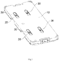
- a testing jointed board comprising: a board body 10 and at least one medium module 20, wherein the medium module 20 is connected to a camera module 30, wherein the camera module 30 is a finished product to be tested, and the camera module 30 is connected to the medium module 20 for performing various performance tests on of camera module 30.
- the camera module 30 can be connected and detachably fixed to the medium module 20, and the medium module 20 can carry the camera module 30 to perform all testing operations. It is to be noted that the connection between the medium module 20 and the camera module 30 is one by one.
- the camera module 30 can complete all testing operations through the medium module 20 without having to be repeatedly connected and fetched relative to the medium module 20.
- the camera module 30 to be tested is connected and fixed to the medium module 20 before starting the testing operation.
- the medium module 20 will carry the camera module 30 for all the tests.
- the medium module 20 will be always connected to the camera module 30 regardless of whether the camera module 30 passes the test. That is, the medium module 20 can also assist the camera module 30 in performing the corresponding operation without passing the test for the camera module 30 that has not passed the test.
- the medium module 20 will also accompany the camera module 30 to complete other tests.
- the camera module 30 can avoid repeated connection and disconnection and fetch during all tests, including the flow process, to reduce adverse effects of the test on the camera module 30, reduce the time required for each of the camera modules 30 to be tested, and improve the overall efficiency of the test.
- the medium module 20 can simultaneously provide a stable connection in the structure and circuit for the camera module 30.
- the medium module 20 provides a circuit expansion of the camera module 30 for testing requirements, and indirectly causes the camera module 30 to be performed various performance tests.
- the camera module 30 can be given a certain protection by the medium module 20, so that the camera module 30 can complete all testing operations by the medium module 20.
- the camera module 30 can be detached from the medium module 20 as needed. For example, after a certain test fails or the entire test is completed, the camera module 30 is tested completely to be detached from the medium module 20, thereby causing the camera module 30 to complete the test.
- the medium module 20 can be adapted to different types of the camera module 30.
- the medium module 20 is less expensive and does not require complicated processes. In this way, the medium module 20 can carry the camera module 30 to be repeatedly tested to reduce the test cost. Moreover, the medium module 20 has a high degree of matching for different test items, and the medium module 20 can participate in different test projects. For the same camera module 30 to be tested, it is not necessary to replace the connected medium modules 20. That is, the medium module 20 can carry different types of the camera module 30 for testing. Therefore, for the testing process of the camera module 30, the camera module 30 and the medium module 20 are mutually corresponding and need not be replaced. For the different types of the camera module 30, the medium module 20 can be adapted, and the medium module 20 can carry different camera modules 30 for testing. For different types of test projects, the medium module 20 has extremely high adaptability to the test equipment, and can ensure that the camera module 30 can effectively complete the testing operation.
- the board body 10 provided by the preferred embodiment is disposed at least two medium modules 20 for testing a plurality of the camera modules 30 during testing.
- the board body 10 may be disposed m ⁇ n medium modules 20 which are arranged in an array, wherein m and n are integers greater than or equal to 2.
- the board body 10 fixes the medium module 20 in an array, and ensures that the environment in which the medium module 20 is located is consistent during the test. That is, the test conditions of all of the medium modules 20 disposed on the testing board are identical. In this way, the test environment of the camera module 30 carried by the medium module 20 can be ensured to be stable.
- the testing board body 10 can be disposed four medium modules 20, and each of the medium modules 20 is connected to the camera module 30 correspondingly.
- the medium module 20 may be taken out from the board body 10 during testing or may be re-mounted to the board body 10. That is, the medium module 20 is detachable relative to the board body 10 during the overall testing process.
- the medium module 20 carries the camera module 30 to be removably disposed on the board body 10 according to different requirements. In the testing process, the camera module 30 is not required to be fetched, and the camera module 30 is operated by the medium module 20.
- the camera module 30 is provided with certain protection.
- the medium module 20 is preferably fabricated from a rigid material suitable for manipulation of the medium module 20 by means of a machine.
- the camera module 30 carried by one of the four medium modules 20 fails to pass the test, and the corresponding medium module 20 is taken out, and thus the camera module 30 that has not passed is fetched.
- the camera module 30 carried by the medium module 20 is disposed on the board body 10 by disposing the medium module 20 on the board body 10.
- the board body 10 is also provided for the identification, positioning, etc. of any of the medium modules 20. Therefore, the test environments in which the medium modules 20 are located are consistent, and any one of the medium modules 20 can be operated separately.
- the medium module 20 in the board body 10 can be conveniently retrieved in form of an array arrangement.
- the medium module 20 is in a one-to-one correspondence with the camera module 30 during the test.
- the board body 10 can ensure that each of the medium modules 20 is at the same height or in the same time level. That is, the camera module 30 can be operated in batches by the medium module 20 and the board body 10. In particular, for the testing operation of the camera module 30 in batches, the medium module 20 and the board body 10 can ensure the consistency and effectiveness of testing of each of the camera modules 30. Moreover, the direct operation of the medium module 20 does not adversely affect the camera module 30.
- the camera module 30 can be tested more efficiently by an indirect operation of the corresponding medium module 20 of the board body 10.
- both the medium module 20 and the board body 10 can free productivity and reduce production costs.
- a corresponding positioning structure is formed between the board bodies 10 of the testing jointed board, between the board body 10 and the medium module 20, and between the medium module 20 and the camera module 30 to ensure the test flow and the search for the board body 10, the medium module 20 and the camera module 30 during the process.
- the medium module 20 can be consistent in height with each of the camera modules 30, and each of the medium modules 20 is consistent in height with the board body 10, so that each of the camera modules 30 has the same height during the test.
- the position of each camera module 30 relative to the medium module 20 is determined, and the position of the medium module 20 relative to the board body 10 is determined, so that the position of the camera module 30 relative to the position in the test thereof is determined.
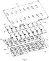
- the board body 10 of the testing jointed board further includes a supporting board 11, wherein the supporting board 11 is disposed on the medium module 20, so that the medium module 20 can be fixed in the board body 10 in a certain arrangement and operated through the board body 10.
- the supporting board 11 of the board body 10 is detachably connected to the medium module 20, so that the medium module 20 placed in the board body 10 can be in a consistent test environment.
- each of the medium modules 20 is detachably connected to the supporting board 11, so that the medium module 20 is disposed or taken out as needed.
- the medium module 20 is preferably snapped to the supporting board.
- the medium module 20 is preferably adapted to be adhesively connected to the supporting board in a host-and-slave manner.
- the medium module 20 is preferably adapted to be magnetically attracted to the supporting board.
- the medium module 20 is preferably adapted to be connected to the supporting board by a post and an aperture.
- the board body 10 further includes a cover 12 and a snapping assembly 13, wherein the cover 12 detachably covers the supporting board 11 to protect the medium module 20 disposed on the supporting board 11, wherein the snapping assembly 13 is disposed on the supporting board 11 and the cover 12 to detachably connect the cover 12 to the supporting board 11. It is obvious that when the medium module 20 is disposed on the supporting board 11 and the snapping assembly 13 fixes the cover 12 to the supporting board 11, the medium module 20 cannot be fetched from the board body 10. Correspondingly, when the medium module 20 needs to be taken out from the board body 10, the snapping assembly 13 is opened, so that the cover 12 can be detached from the supporting board 11, so that the medium module 20 can be taken out.
- the board body 10 according to the embodiment of the present invention may not include the above-mentioned cover 12.
- the board body 10 according to an embodiment of the present invention may include only a single supporting board 11.
- the usage of the board body 10 in combination with the medium module 20 of the embodiment of the present invention is taken as an embodiment, those skilled in the art can understand that a testing board in which the board body 10 is combined with the medium module 20 of the embodiment of the present invention can also be used separately.
- the testing board can be directly connected to the camera module 30 without the medium module 20.
- the testing board is fabricated by integrally forming the medium module 20 and the board body 10. Then, the camera module 30 is adapted to be directly connected to the testing board for testing.
- a testing board for testing optical performance of a camera module including a board main body, and at least two accommodating positions disposed on the board main body, the accommodating position is for accommodating a testing unit, and the testing unit includes at least assembled camera module.
- the testing unit comprises both an assembled camera module and a medium module connected to the camera module.
- the testing board according to the embodiment of the present invention can selectively connect different camera modules according to actual needs, that is, the embodiment of the present invention does not limit that at least two accommodating positions on the board main body are the accommodating positions of same size, and may also be accommodating positions of different sizes. Even if necessary, the accommodating position of the testing board can be used to accommodate the camera module and the medium module connected to the camera module respectively.
- the testing board can accommodate only the assembled camera module, only the medium module connected to the camera module, or both the camera module and the medium module.
- the camera module 30 can avoid repeated mounting and fetching during all tests, including the flow process, to reduce the adverse effects of the test on the camera module 30, reduce the time required for each of the camera modules 30 to be tested, and improve the overall efficiency of the test.
- the testing board according to an embodiment of the present invention further includes a fixing component for fixing the testing unit in the accommodating position.
- the fixing component may be the above-described component for snapping the medium module to the supporting board, or a component for adhesively connecting the medium module to the supporting board in host-and-slave manner, or a component for magnetically attracting the medium module to the supporting board.
- cover 12 and the snapping assembly 13 on one hand, they acts as a fixing component for fixing the testing unit in the accommodating position, and on the other hand, plays the role of protecting the testing unit accommodated in the accommodating position.
- the testing board according to an embodiment of the present invention further includes a protection component for protecting the testing unit accommodated in the accommodating position.
- the fixing component and the protection component are preferable, but are not essential. Specifically, in the test of the optical performance of the camera module, in most cases the testing board remains horizontally placed, and the testing board also moves horizontally along with the camera module during the test. Therefore, if the specific test conditions determine that the camera module does not cause sufficient displacement in the accommodating position of the testing board, the fixed components are not necessarily required.
- the testing board and the testing jointed board composed of the board body 10 and the medium module 20 are similar in function to the camera module 30.
- the testing jointed board is mainly explained in detail.
- the medium module 20 is disposed in a 2x2 array form on the supporting board 11 of the board body 10 of the testing jointed board.
- Each of the medium modules 20 is disposed at a certain determined position.
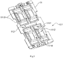
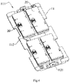
- the supporting board 11 provides at least one testing position 111, wherein the testing position 111 is correspondingly disposed the medium module 20, so that the camera module 30 carried by the medium module 20 is placed in the determined position.
- the supporting board 11 of the testing jointed board in the preferred embodiment has four testing positions 111, which can be placed with four medium modules 20, respectively.
- the testing position 111 further includes a testing interface portion 1111, a recognizing portion 1112, a positioning portion 1113, and a placement portion 1114.
- the structure of the testing position 111 corresponds to the structure of the medium module 20. That is, in the preferred embodiment, the testing interface portion 1111 is an interface through hole provided to the medium module 20, and the recognizing portion 1112 is a through hole for recognizing identity of the camera module 30 carried by the medium module 20.
- the positioning portion 1113 is a positioning structure relative to the medium module 20, and the placement portion 1114 is a placement position of the camera module 30 corresponding to the medium module 20.
- each testing position 111 is consistent, which facilitates the adaptive placement of the medium module 20. More specifically, the testing interface portion 1111 is two symmetric through holes in the preferred embodiment, and the testing interface portion 1111 allows the interface of the test equipment to be connected to the medium module 20. Of course, according to the design of the medium module 20, the position and shape of the testing interface portion 1111 need to be adjusted accordingly.
- the recognizing portion 1112 is a position identified corresponding to the camera module 30 that is carried. In the preferred embodiment, the recognizing portion 1112 is a through hole that can recognize the identity of the camera module 30. Through the recognizing portion 1112, the identity of the camera module 30 can be recognized.
- the shape and form of the recognizing portion 1112 can be adjusted according to the identification manner of the camera module 30.
- the recognizing portion 1112 when it is necessary to recognize the identity by scanning the identification code, the recognizing portion 1112 is a through hole for passing light, and when it is necessary to identify the RFID information, the recognizing portion 1112 is a corresponding position that can be recognized.
- the positioning portion 1113 is a structure that is mutually positioned with the medium module 20, so that the position of the testing interface portion 1111 and the recognizing portion 1112 relative to the supporting board 11 is determined.
- the position of each of the positioning portions 1113 and the medium module 20 is mutually determined, that is, it can be ensured that the position of all the medium modules 20 relative to the supporting board 11 is determined.
- the medium module 20 is square, and the positioning portion 1113 is a positioning post in a diagonal direction relative to the medium module 20.
- the positioning portion 1113 may specifically be a magnetic sheet, a snap pile or the like.
- the placement portion 1114 is a flexible sheet that is fixed to the testing position 111, and provides a height replenishment and buffer for the camera module 30 of the medium module 20.
- the design of the placement portion 1114 can also be adjusted according to the design of the medium module 20.
- the design of the testing portion 111 corresponds to the design of the medium module 20, and the specific structure of each of the testing portions 111 is mainly for satisfying the stability and power supplying conditions of the medium module 20.
- the supporting board 11 of the testing jointed board has at least one calibrating position 112, and the calibrating position 112 is located at a central axis of the supporting board 11.
- the calibrating position 112 provides a calibration of the position of the supporting board 11, that is, the specific position of the supporting board 11 can be determined based on the calibrating position 112.
- the cover 12 also has a calibrating position 122 corresponding to the supporting board 11, that is, the overall position of the board body 10 can be determined by the mutual calibration of the calibrating position 112 of the supporting board 11 and the calibrating position 122 of the cover 12.
- the cover 12 is further provided with at least one light passing opening 120 to provide a light passing condition for testing of the camera module 30. It can be understood by those skilled in the art that the light passing opening 120 may be in one-to-one correspondence with the camera module 30, or may be a one-to-many opening configuration, and does not affect the technical scope of the present invention.
- the specific case in which the medium module 20 of the preferred embodiment is disposed on the board body 10 is as shown in Fig. 6 .
- the medium module 20 is disposed on the supporting board 11 of the board body 10, and the cover 12 covers and fixes the medium module 20 to the support board 11.
- the snapping assembly 13 snaps and fixes the cover 12 and the supporting board 11 to fix the position of each of the medium modules 20.
- the board body 10 can stably fix each of the medium modules 20, and the camera module 30 carried by each of the medium modules 20 is placed in the same test environment. It is to be noted that, for each of the board body 10 used in the test, the positions of the medium modules 20 between the board bodies 10 are relatively determined.
- the camera module 30 of the medium module 20 can find the medium module 20 of the board body 10 by finding the board body 10.
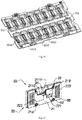
- the medium module 20 in the preferred embodiment is shown in Fig. 8 to Fig. 10 .
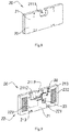
- the medium module 20 further includes a substrate 21 and an expansion circuit 22, the expansion circuit 22 being embedded in the substrate 21, and the substrate 21 is preferably integrally formed.
- the medium module 20 is adapted to be connected to the camera module 30.
- the camera module 30 is connected to the test equipment by the medium module 20 and is protected by the medium module 20. The operation of the camera module 30 during the testing process and the flow is completed by the medium module 20.
- the further structure of the camera module 30 is illustrated here, mainly including a lens 31, a plug 32 and a mark 33.
- the mark 33 is an identifier for the camera module 30. Then, as shown in Fig.
- the substrate 21 further includes a fixed position 211 adapted to connect and fix the camera module 30. More specifically, the fixed position 211 is provided with a lens groove 2111 for placing the lens 31 of the camera module 30.
- the fixed position 211 of the substrate 21 further includes a socket 2112, and the socket 2112 can be closely connected to the plug 32 of the camera module 30.
- the camera module 30 can be stably fixed to the substrate 21 through the connection of the lens groove 2111 and the socket 2112.
- the fixed position 211 has adaptability, and can be placed with and connected to different types of camera modules 30.
- the camera module 30 is a single camera module, and the lens groove 2111 allows the lens 31 of the camera module 30 to be entirely placed in.
- the socket 2112 is also adapted to the plug 32 of the camera module 30. That is, in order to adapt to the camera module 30, the structure of the fixed position 211 is disposed correspondingly. However, the fixed position 211 not only connects the camera module 30 to the substrate 21 but also ensures that the camera module 30 is always operated by the medium module 20 during the testing process and the flow. More specifically, each of the medium modules 20 will correspond to the camera module 30 during the testing process and the flow, and the fixed position 211 can provide stability of the camera module 30 in structure and circuit connection. It is to be noted that, in the preferred embodiment, the socket 2112 of the fixed position 211 is in form of a connector, so that the camera module 30 is not easily dropped during operation.
- the expansion circuit 22 of the medium module 20 further includes a module interface 221, a testing interface 222, and a trace 223 connected to the module interface 221 and the testing interface 222.
- the module interface 221 and the testing interface 222 are correspondingly connected by the trace 223.
- the module interface 221 and the testing interface 222 are connected to each other in a certain manner and corresponding relationship.
- the module interface 221 is built in the socket 2112 of the fixed position 211, so that when the plug 32 of the camera module 30 is connected to the socket 2112, the circuit of the camera module 30 and the expansion circuits 22 are connected to each other.
- the circuit of the camera module 30 is connected to the expansion circuit 22, so that the camera module 30 can be tested through the testing interface 222 of the expansion circuit 22. That is, after the camera module 30 is connected to the expansion circuit 22, the test of the camera module 30 can be performed through the testing interface 222 of the expansion circuit 22.
- the testing interface 222 provides the corresponding access port to the test equipment to perform the test on the camera module 30 carried by the medium module 20.
- the testing interface 222 is preferably disposed in form of an electrical contact on the surface of the substrate 21 for electrically connecting probes of the test equipment by contacting. More preferably, the testing interface 222 in the preferred embodiment adopts a distributed arrangement, so that the testing interface 222 can be more stably and accurately contacted.
- the testing interface 222 is preferably symmetrically arranged on the surface of the substrate 21 in two parts.
- the testing interface 222 may be a one-piece layout, where the layout of the testing interface 222 of the present invention is not limited.
- the substrate 21 of the medium module 20 further includes at least one positioning member 213, and the positioning member 213 is disposed correspondingly to the positioning portion 1113 of the testing position 111 of the supporting board 11 of the board body 10. That is, the positioning member 213 of the medium module 20 is disposed correspondingly to the positioning portion 1113 of the board body 10, so that the relative position of the medium module 20 and the board body 10 is determined.
- the medium module 20 is square, and the positioning member 213 is a positioning hole in a diagonal direction relative to the medium module 20.
- the positioning member 213 may specifically be a magnetic sheet, a snap pile or the like.
- the positioning member 213 is disposed correspondingly to the positioning portion 1113, that is, the positioning member 213 and the positioning portion 1113 are paired.
- the positioning member 213 is matched with the positioning portion 1113, the medium module 20 is mutually positioned with the testing position 111 of the board body 10.
- the medium modules 20 are all positioned with the board body 10. It can be understood that, when the camera module 30 and the medium module 20 are fixed to each other, and the medium module 20 and the board body 10 are mutually positioned, the position of each camera module 30 in the board body 10 can also be determined.
- the board body 10 can be positioned by the mark 112, the relative position of the camera module 30 during the testing process can be determined. It can be understood that positioning information of the medium module 20 that the camera module 30 is at a position of which of the board body 10 is very important for the entire batch test.
- FIG. 11 to Fig. 16 Another possible preferred embodiment of the invention is shown in Fig. 11 to Fig. 16 . Similar to the above embodiment, the preferred embodiment also provides a board body 10 and a medium module 20, wherein the medium module 20 is connected to a camera module 30, wherein the camera module 30 is a finished product to be tested. The camera module 30 is connected to the medium module 20 for performance testing of the camera module 30.
- the board body 10 provided by the preferred embodiment is disposed with sixteen medium modules 20 for testing up to sixteen camera modules 30 at the same time.
- the board body 10 can be disposed with 2 x 8 of the medium modules 20 which are arranged in an array.
- the board body 10 fixes the medium module 20 in an array form, and ensures that the environment of the medium module 20 is consistent during the test. That is, the test conditions of all of the medium modules 20 disposed on the testing board are identical. In this way, the test environment of the camera module 30 carried by the medium module 20 can be ensured to be stable.
- the board body 10 further includes a supporting board 11, wherein the supporting board 11 is disposed on the medium module 20, so that the medium module 20 can be fixed in the board body 10 in a certain arrangement and operated by the board body 10.
- the supporting board 11 of the board body 10 is detachably connected to the medium module 20, so that the medium module 20 placed in the board body 10 can be in a consistent test environment.
- the medium module 20 is preferably connected to the testing position 111 of the supporting board 11 by a post and an aperture.
- the board body 10 further includes a cover 12 and a snapping assembly 13, wherein the cover 12 detachably covers the supporting board 11 to protect the medium module disposed on the supporting board 11, wherein the snapping assembly 13 is disposed on the supporting board 11 and the cover 12 to detachably connect the cover 12 to the supporting board 11.
- the snapping assembly 13 is opened, so that the cover 12 can be fetched from the supporting board 11, thereby the medium module 20 can be taken out.
- the snapping assembly 13 fixes the cover 12 to the supporting board 11, the medium module 20 cannot be fetched from the board body 10.
- the medium modules 20 are disposed on the supporting board 11 of the board body 10 in a 2 x 8 array form. Each of the medium modules 20 is disposed at a certain determined position.
- the supporting board 11 provides at least one testing position 111, wherein the testing position 111 is correspondingly disposed on the medium module 20, and the camera module 30 carried by the medium module 20 is placed in a determined position.
- the supporting board 11 has sixteen testing positions 111, which can correspondingly be placed with sixteen medium modules 20.
- the testing position 111 further includes a testing interface portion 1111, a recognizing portion 1112, a positioning portion 1113, and a placement portion 1114. It is to be noted that the structure of the testing position 111 corresponds to the structure of the medium module 20.
- the interface 1111 is an interface through hole provided to the medium module 20, and the recognizing portion 1112 is a through hole for recognizing identity of the camera module 30 carried by the medium module 20.
- the positioning portion 1113 is a positioning structure relative to the medium module 20, and the placement portion 1114 is a placement position corresponding to the camera module 30 of the medium module 20. It is to be noted that the structure of each testing position 111 is consistent, which facilitates the adaptive placement of the medium module 20.
- the position of each of the positioning portions 1113 and the medium module 20 is mutually determined, that is, the position of all of the medium modules 20 relative to the supporting board 11 can be determined. This facilitates increasing the efficiency of the testing operation of the medium module 20.
- the medium module 20 is square, and the positioning portion 1113 is a positioning hole in a diagonal direction relative to the medium module 20.
- the design of the testing portion 111 corresponds to the design of the medium module 20, and the specific structure of each of the testing portions 111 is mainly to satisfy the stability and power supplying conditions of the medium module 20.
- the supporting board 11 has at least one calibrating position 112, and the calibrating position 112 is located at the central axis of the supporting board 11.
- the calibrating position 112 provides a calibration of the position of the supporting board 11, that is, the specific position of the supporting board 11 can be determined based on the calibrating position 112.
- the calibrating position 112 is present separately on the supporting board 11 and does not have correspondence on the cover 12. That is, in the preferred embodiment, the entire board body 10 is only calibrated by the calibrating position 112 of the supporting board 11.
- the cover 12 further provides at least one light passing opening 120 to provide a light-passing condition for testing of the camera module 30.
- the light passing port 120 can be applied to all types of the camera modules. Only the supporting board 11 needs to be calibrated to determine the position of the board body 10.
- the configuration of the light-passing opening 120 of the cover 12 does not affect the test conditions, nor does it require a separate calibration.
- the medium module 20 has a one-to-one correspondence with the camera module 30 during the testing process.
- the board body 10 can ensure that each of the medium modules 20 is at the same height or in the same time level. That is, the camera module 30 can be operated in batches by the medium module 20 and the board body 10. In particular, for the testing operation of the camera module 30 in batches, the medium module 20 and the board body 10 can ensure the consistency and effectiveness of testing of each of the camera modules 30.
- the direct operation of the medium module 20 does not adversely affect the camera module 30.
- the camera module 30 can be tested more efficiently by the indirect operation of the corresponding medium module 20 of the board body 10.
- the medium module 20 is disposed on the supporting board 11 of the board body 10, and the cover 12 covers and fixes the medium module 20 to the support board 11. As shown in Fig. 14 , the snapping assembly 13 snaps and secures the cover 12 and the supporting board 11 to fix the position of each of the medium modules 20.
- the board body 10 can stably fix each of the medium modules 20, and the camera module 30 carried by each of the medium modules 20 is in the same test environment. It is to be noted that, for each of the board body 10 used in the test, the positions of the medium modules 20 between the board bodies 10 are relatively determined.
- the camera module 30 of the medium module 20 can correspond to the medium module 20 of the board body 10 by corresponding to the board body 10.
- the medium module 20 in the preferred embodiment is as shown in Fig. 15 . It should be noted that the medium module 20 is functionally similar to the aforementioned preferred embodiment. That is, the medium module 20 further includes a substrate 21 and an expansion circuit 22, which are separately disposed on a circuit board, and the substrate 21 is a cover plate of a circuit board of the expansion circuit 22. Preferably, the circuit board of the expansion circuit 22 is made of PCB material.
- the medium module 20 is adapted to be connected to the camera module 30.
- the camera module 30 is connected to the test equipment by the medium module 20 and is protected by the medium module 20. The operation of the camera module 30 during the testing process and the flow is completed through the medium module 20.
- the structure of the camera module 30 is further illustrated here as a lens 31, a plug 32 and an identifier 33, wherein the identifier 33 is an identity of the camera module 30.
- the substrate 21 further includes a fixed position 211 adapted to connect and fix the camera module 30. More specifically, the fixed position 211 is provided with a lens groove 2111 for placing the lens 31 of the camera module 30.
- the circuit board of the expansion circuit 222 further includes a socket 2112, and the socket 2112 can be closely connected to the plug 32 of the camera module 30.
- the expansion circuit 22 of the medium module 20 further includes a module interface 221, a testing interface 222, and a trace 223 connected to the module interface 221 and the testing interface 222.
- the module interface 221 and the testing interface 222 are correspondingly connected by the trace 223.
- the module interface 221 and the testing interface 222 are connected to each other in a certain manner and corresponding relationship.
- the module interface 221 is built in the socket 2112, so that when the plug 32 of the camera module 30 is connected to the socket 2112, the circuit of the camera module 30 and the expansion circuit 22 are connected to each other. Further, the circuit of the camera module 30 is connected to the expansion circuit 22, so that the camera module 30 can be tested through the testing interface 222 of the expansion circuit 22. That is, after the camera module 30 is connected to the expansion circuit 22, the test of the camera module 30 can be performed through the testing interface 222 of the expansion circuit 22.
- the camera module 30 can be stably fixed to the medium module 20 by the connection of the lens groove 2111 and the socket 2112. Moreover, the lens groove 2111 has an adaptability, and can be placed on and connected to different types of the camera module 30.
- the camera module 30 is a dual camera module, and the lens groove 2111 allows the lens 31 of the camera module 30 to be entirely placed in.
- the socket 2112 is also adapted to the plug 32 of the camera module 30.
- the medium module 20 not only connects the camera module 30 to the substrate 21 and the expansion circuit 22, but also ensures that the camera module 30 is always operated through the medium module 20 during the testing process and the flow. More specifically, each of the medium modules 20 will correspond to the camera module 30 in the test process and the flow.
- the socket 2112 of the fixed position 211 is adopted a form of a connector, so that the camera module 30 is not easily dropped during operation.
- the camera module 30 maintains a stable connection relationship relative to the medium module 20 by the fixing of the substrate 21 and the expansion circuit 22.
- the testing interface 222 is disposed on the surface of the substrate 21 in a form of electrical contacts for probes of the test equipment to be electrically connected by contacting. More preferably, the testing interface 222 in the preferred embodiment adopts a symmetric distributed arrangement, and a certain gap is maintained between each electrical contact, so that the testing interface 222 can be more stably and accurately contacted.
- the circuit board of the expansion circuit 22 of the medium module 20 further includes at least one positioning member 213, and the positioning member 213 is disposed corresponding to the positioning portion 1113 of the testing position 111 of the supporting board 11 of the board body 10. That is, the positioning member 213 of the medium module 20 and the positioning portion 1113 of the board body 10 are disposed corresponding to each other, so that the relative position of the medium module 20 and the board body 10 is determined.
- the medium module 20 is square
- the positioning member 213 is a positioning post in a diagonal direction relative to the medium module 20.
- the positioning member 213 and the positioning portion 1113 are disposed corresponding to each other, that is, the positioning member 213 and the positioning portion 1113 are paired.
- the medium module 20 and the testing position 111 of the board body 10 mutually determine the position.
- the medium modules 20 are all positioned with the board body 10. It can be understood that, when the camera module 30 and the medium module 20 are fixed to each other, and the medium module 20 and the board body 10 are mutually positioned, the position of each camera module 30 in the board body 10 can also be determined.
- the position of the camera module 30 can be more accurately ensured by the positioning of the positioning member 213 of the circuit board of the expansion circuit 22.
- a test equipment for applying the board body 10 and the medium module 20 is as shown in Fig. 16 .
- the test equipment has a testing circuit 40 that is adapted to the board body 10.
- the test equipment is connected to the medium module 20 of the board body 10 through the testing circuit 40, so that a plurality of the medium modules 20 disposed in the board body 10 are simultaneously connected to the test equipment, and the camera module 30 carried by the module 20 is simultaneously tested.
- the connection between the medium module 20 and the camera module 30 is one by one. That is, the camera module 30 can complete all testing operations through the medium module 20 without having to be repeatedly connected and fetched relative to the medium module 20.
- the camera module 30 to be tested is connected and fixed to the medium module 20 before starting the testing operation.
- the medium module 20 will carry the camera module 30 for all tests.
- the medium module 20 will always connect to the camera module 30 regardless of whether the camera module 30 passes the test. That is, the medium module 20 can also assist the camera module 30 in performing the corresponding operation for failing to pass the test for the camera module 30 that has not passed the test.
- the medium module 20 will also accompany the camera module 30 to complete other tests.
- the medium module 20 provides an adapted testing interface, the testing circuit 40 only requires a corresponding interface, and the medium module 20 can perform different performance test projects. Through the medium module 20, the camera module 30 can avoid repeated connection and fetching during all tests, including the flow process, to reduce the time required for each of the camera modules 30 to be tested, and improve the overall efficiency of the test, which is suitable for testing of the camera module 30 in batches.
Landscapes
- Engineering & Computer Science (AREA)
- Physics & Mathematics (AREA)
- General Physics & Mathematics (AREA)
- Health & Medical Sciences (AREA)
- Biomedical Technology (AREA)
- General Health & Medical Sciences (AREA)
- Multimedia (AREA)
- Signal Processing (AREA)
- Studio Devices (AREA)
- Accessories Of Cameras (AREA)
- Camera Bodies And Camera Details Or Accessories (AREA)
Abstract
Description
- The invention relates to a camera module testing medium module, a testing jointed board and a testing board, in particular to a testing jointed board and a testing board which are composed of medium modules used for batch camera module testing.
- With the development of smart devices, more and more smart devices are inseparable from image acquisition function. Moreover, high-performance imaging and photographing functions are being pursued by the market. For example, a smart phone, a laptop computer, and a smart wearable device are all developed toward higher-performance imaging functions. Performance parameters are also constantly updated as the market changes. These miniature imaging applications are inseparable from the use of camera modules.
- At present, there are still many unstable factors in the production of the camera module, and the manufactured camera module cannot be directly installed in the device. Then each camera module needs to be tested with different performance parameters, and camera modules that do not meet the requirements cannot be used. For the manufacturer, the yield of the product is important, and the yield of the shipped product is even more critical. Therefore, in the production of camera modules, it is basically to take all products for all tests. This undoubtedly increases production costs and reduces production efficiency.
- In the conventional production process of the camera module, each camera module is sequentially tested in various ways. That is, for a large number of products, the test is carried out separately. However, at present, production tends to be mass-produced in production, and the conventional camera module test cannot meet the requirements of mass production. In addition, in the traditional test, the camera module is connected to the test equipment or the test environment, and after the test is completed, the camera module is got back. Moreover, the number of test items required is also large, and repeated fetch and connection and disconnection of the camera module will inevitably have an adverse effect on the camera module. Taking into account the cost of time, the separate connection and disconnection of the camera module in each test will affect efficiency. In particular, traditionally, test of each camera module is manual, requires manual connection and fetch operations, to actively maintain the test environment. This will bring more adverse factors to the test, and it will not be able to adapt to the development trend.
- A conventional test relay terminal of the camera module is connected by all the pins of the camera module to trap the camera module in the terminal by using at least two layers of snaps. Moreover, contact pins are relatively concentrated, and circuit of the camera module is switched by a cable, and usually at least two transfers are required to be connected with the test equipment. At the end of each test, the camera module needs to be taken out and then connected to the next test environment. The pin of the conventional relay terminal has higher requirements on accuracy, and the repeated connection and fetch damage to the circuit is serious, and the service life is short. And different types of camera modules need different structures to be fixed, otherwise, the camera module will be detached. In addition, not all the tests of the camera module can be adapted, and the labor cost is high.
- How to test various performances of the camera module in batches during the test is currently a problem. Moreover, in the process of testing a plurality of camera modules, how to ensure the validity and accuracy in multiple processes such as connection, test, and fetch is also a problem that must be solved. In addition, in order to adapt to different types of camera modules that are carried out different test methods, the adaptability of the test environment is also considered. Although it is said that compared with manual, mechanical has certain advantages in terms of precision, how to overcome the tolerance formed on mechanical flow in practice is also one of the challenges.
- An object of the present invention is to provide a camera module testing medium module, a testing jointed board and a testing board, so that a camera module is connected to a medium module, and is tested for performance through the medium module.
- Another object of the present invention is to provide a camera module testing medium module, a testing jointed board and a testing board, and provide a testing jointed board being adapted to be disposed at least two medium modules, and simultaneously perform performance testing to the medium modules in the testing jointed board.
- Another object of the present invention is to provide a camera module testing medium module, a testing jointed board and a testing board, and provide a testing board provided with at least two accommodating positions which are each adapted to accommodate a testing unit including at least an assembled camera module to be tested.
- Another object of the present invention is to provide a camera module testing medium module, a testing jointed board and a testing board, and the testing unit includes at least one of the assembled camera modules to be tested and the medium modules connected to the camera modules.
- Another object of the present invention is to provide a camera module testing medium module, a testing jointed board and a testing board, and the medium module is structurally and electrically connected to the camera module, so that the test is performed through the medium module and test results of the camera module is obtained.
- Another object of the present invention is to provide a camera module testing medium module, a testing jointed board and a testing board, and the medium module further includes a substrate for connecting and detachably fixing the camera module and an expansion circuit for electrically connected to the camera module.
- Another object of the present invention is to provide a camera module testing medium module, a testing jointed board and a testing board, and the substrate of the medium module is provided with a lens groove, so that the camera module is optically connected to the substrate, and is suitable for various performance tests.
- Another object of the present invention is to provide a camera module testing medium module, a testing jointed board and a testing board, and the substrate of the medium module is provided with a socket, so that the camera module is connected to the expansion circuit through the socket and tested by the expansion circuit.
- Another object of the present invention is to provide a camera module testing medium module, a testing jointed board and a testing board, and the socket provides a certain fixing function for the connection of the camera module.
- Another object of the present invention is to provide a camera module testing medium module, a testing jointed board and a testing board, and the medium module carries the camera module to perform various tests without repeated fetch, thereby reducing adverse effects.
- Another object of the present invention is to provide a camera module testing medium module, a testing jointed board and a testing board, and the medium module gives a certain protection to the camera module, and is further adapted to carry the camera module to be repeatedly tested. Another object of the present invention is to provide a camera module testing medium module, a testing jointed board and a testing board, and the medium module can be matched with the camera modules of different shapes to facilitate to perform different types of tests to different types of the camera modules.
- Another object of the present invention is to provide a camera module testing medium module, a testing jointed board and a testing board, and the medium module carries the camera module to complete all tests of the camera module.
- Another object of the present invention is to provide a camera module testing medium module, a testing jointed board and a testing board, and the medium module can be reused to reduce cost of testing.
- Another object of the present invention is to provide a camera module testing medium module, a testing jointed board and a testing board, and the expansion circuit of the medium module provides a module interface and a testing interface, so that the camera module performs testing indirectly through the medium module, which is beneficial to maintain integrity of the camera module.
- Another object of the present invention is to provide a camera module testing medium module, a testing jointed board and a testing board, and the testing interface of the medium module can be connected to different performance testing ports, and the medium module can be kept unchanged during testing of a single camera module.
- Another object of the present invention is to provide a camera module testing medium module, a testing jointed board and a testing board, and structure and circuit of the medium module have high stability, and the impact on the camera module during the test is reduced.
- Another object of the present invention is to provide a camera module testing medium module, a testing jointed board and a testing board, and the testing jointed board is preferably disposed a plurality of the medium modules in an array to facilitate positioning and identification of the camera module carried by the medium module.
- Another object of the present invention is to provide a camera module testing medium module, a testing jointed board and a testing board, and the testing interface adopts a distributed design, which is more convenient when the test equipment is connected to the medium module. Another object of the present invention is to provide a camera module testing medium module, a testing jointed board and a testing board, and the testing board further comprises a supporting board which provides m×n testing positions for the medium modules to be disposed on the testing positions for various performance tests.
- Another object of the present invention is to provide a camera module testing medium module, a testing jointed board and a testing board, and the testing position and the medium module are correspondingly disposed to provide a corresponding testing interface portion for the testing interface.
- Another object of the present invention is to provide a camera module testing medium module, a testing jointed board and a testing board, and the testing position of the testing jointed board further includes a positioning portion, a placement portion and a recognizing portion to ensure the effectiveness of the test of the camera module.
- Another object of the present invention is to provide a camera module testing medium module, a testing jointed board and a testing board, and the testing jointed board can ensure that the test environment of a plurality of the camera modules disposed therein is consistent by the testing position.
- Another object of the present invention is to provide a camera module testing medium module, a testing jointed board and a testing board, and the testing jointed board further provides a calibration portion for conveniently calibrating the overall position of the testing jointed board. Another object of the present invention is to provide a camera module testing medium module, a testing jointed board and a testing board, and since the medium module is applicable to different camera modules, the test jointed boards correspondingly disposed are also applicable to different performance tests of different camera modules.
- Another object of the present invention is to provide a camera module testing medium module, a testing jointed board and a testing board, and the testing jointed board provides a more convenient connection manner and is suitable for convenient connection of test equipment. According to an aspect of the present invention, the present invention further provides a medium module for testing optical performance of a camera module, comprising:
- a substrate; and
- an expansion circuit disposed on the substrate and adapted to be connected to the camera module, to provide an adaptive circuit switching for the camera module.
- According to an embodiment of the present invention, the expansion circuit further comprises a module interface, a testing interface, and a trace connected to the module interface and the testing interface.
- According to an embodiment of the present invention, the module interface and the testing interface are correspondingly connected by the trace.
- According to an embodiment of the present invention, the camera module is connected to the expansion circuit through the module interface.
- According to an embodiment of the present invention, the testing interface is disposed on the substrate in a form of electrical contacts for electrically connecting probes of a test equipment by contacting.
- According to an embodiment of the present invention, the substrate further comprises a fixed position adapted to connect and detachably fix the camera module.
- According to an embodiment of the present invention, the fixed position is provided with a lens groove for placing a lens of the camera module.
- According to an embodiment of the present invention, the expansion circuit is embedded in the substrate integrally formed in advance.
- According to an embodiment of the present invention, the expansion circuit is formed as a circuit board independent of the substrate, and the substrate closely covers the circuit board.
- According to an embodiment of the present invention, the substrate further comprises a socket closely connected to the camera module.
- According to an embodiment of the present invention, the camera module is stably fixed to the medium module by the connection of the lens groove and the socket.
- According to an embodiment of the present invention, the fixed position is adaptable by the connection of the lens groove and the socket.
- According to an embodiment of the present invention, the module interface is built in the socket, so that when the camera module is connected to the socket, the camera module and the expansion circuit are electrically connected.
- According to another aspect of the present invention, the present invention provides a testing jointed board for testing optical performance of a camera module, comprising:
- a board body; and
- at least two medium modules disposed on the board body, wherein each medium module is connected to a camera module to perform test of optical performance of the camera module through the board body.
- According to an embodiment of the present invention, the camera module is detachably fixed to the medium module, so that the medium module carries the camera module to perform a testing operation.
- According to an embodiment of the present invention, the medium module in the board body is connected to the camera module one by one.
- According to an embodiment of the present invention, the medium module further comprises a substrate and an expansion circuit, wherein the expansion circuit is disposed on the substrate, and the substrate is adapted to be connected to the camera module, and the expansion circuit is adapted to be connected to the camera module, to provide an adaptive circuit switching for the camera module.
- According to an embodiment of the present invention, the medium module provides a stable connection in the structure and circuit for the camera module, and the camera module is operated through the medium module, so that the camera module is indirectly tested.
- According to an embodiment of the present invention, the testing jointed board is disposed with m x n of the medium modules which are arranged in an array, wherein m and n are integers greater than or equal to 2.
- According to an embodiment of the present invention, the board body further comprises a supporting board, wherein the supporting board is adapted to dispose the medium module, so that the medium module is fixed on the board body in a certain arrangement and is operated through the testing jointed board.
- According to an embodiment of the present invention, each of the medium modules is detachable connected to the supporting board, so that the medium module is disposed on or fetched from the board body as needed.
- According to an embodiment of the present invention, the medium module is snapped to the supporting board.
- According to an embodiment of the present invention, the medium module is adhesively connected to the supporting board in a host-and-slave manner.
- According to an embodiment of the present invention, the medium module is magnetically attracted to the supporting board.
- According to an embodiment of the present invention, the medium module is snapped connected to the supporting board by a post and an aperture.
- According to an embodiment of the present invention, the board body further comprises a cover and a snapping assembly, wherein the cover detachably covers the supporting board to protect the medium module disposed on the supporting board, and the snapping assembly is disposed on the supporting board and the cover to detachably connect the cover to the supporting board. According to an embodiment of the present invention, the supporting board provides at least four testing positions to correspondingly dispose the medium module, so that the camera module carried by the medium module is placed in the testing position.
- According to an embodiment of the present invention, the testing position further comprises a testing interface portion, wherein the testing interface portion provides a through hole of electrical connection to the medium module.
- According to an embodiment of the present invention, the testing position further comprises a recognizing portion, wherein the recognizing portion is a through hole for recognizing identity of the camera module carried by the medium module.
- According to an embodiment of the present invention, the testing position further comprises a placement portion, wherein the placement portion provides a position for the camera module corresponding to the medium module.
- According to an embodiment of the present invention, the testing position further comprises a positioning portion, wherein the positioning portion provides positioning relative to the medium module.
- According to an embodiment of the present invention, the supporting board has at least one calibrating position, wherein the calibrating position provides calibration of the position of the supporting board.
- According to an embodiment of the present invention, the medium module further comprises at least one positioning member, the positioning member is disposed corresponding to the positioning portion of the testing position of the supporting board of the board body to determine the position of the medium module relative to the board body.
- According to an embodiment of the present invention, the positioning member is a positioning hole in a diagonal direction relative to the medium module, and the positioning portion is a positioning rod corresponding to the positioning member.
- According to another aspect of the present invention, the present invention provides a test equipment for testing at least four camera modules using the testing jointed board.
- According to another aspect of the present invention, the present invention provides a testing board for testing optical performance of the camera module, comprising:
- a board main body; and
- at least two accommodating positions disposed on the board main body;
- According to an embodiment of the present invention, the testing unit comprises at least one of the assembled camera module to be tested and a medium module connected to the camera module.
- According to an embodiment of the present invention, the testing board further comprising: a fixing component for fixing the testing unit in the accommodating position.
- According to an embodiment of the present invention, the testing board further comprising: a protecting component for protecting the testing unit accommodated in the accommodating position.
- According to an embodiment of the present invention, the board main body further has at least one calibrating component that provides calibration of position and orientation of the testing board.
- According to an embodiment of the present invention, the testing unit further comprises a positioning member, the board main body further comprising a positioning portion, wherein the positioning portion is disposed corresponding to the positioning member, so that position of the testing unit relative to the board main body is determined.
- According to an embodiment of the present invention, the testing unit is detachably fixed to the board main body, and the accommodating position of the board main body is connected to the testing unit one by one.
- According to an embodiment of the present invention, the testing board further provides an expansion circuit, wherein the expansion circuit is adapted to be connected to the testing unit, to provide an adaptive circuit switching for the testing unit.
-
-
Fig. 1 is a schematic view of a testing jointed board and a medium module in accordance with a preferred embodiment of the present invention. -
Fig. 2 is an exploded schematic view of the testing jointed board and the medium module in accordance with the above-described preferred embodiment of the present invention. -
Fig. 3 is a schematic view of a supporting board of the testing jointed board in accordance with the above-described preferred embodiment of the present invention. -
Fig. 4 is a schematic view of the medium module being disposed on the testing jointed board in accordance with the above-described preferred embodiment of the present invention. -
Fig. 5 is a schematic view of the medium module being disposed on the testing jointed board in accordance with the above-described preferred embodiment of the present invention. -
Fig. 6 is a cross-sectional view of the medium module disposed on the testing jointed board in accordance with the above-described preferred embodiment of the present invention. -
Fig. 7 is a schematic view of a snapping assembly of the testing jointed board in accordance with the above-described preferred embodiment of the present invention. -
Fig. 8 is an overall schematic view of the medium module in accordance with the above-described preferred embodiment of the present invention. -
Fig. 9 is an overall schematic view of the medium module adapted to be connected to the camera module in accordance with the above-described preferred embodiment of the present invention. -
Fig. 10 is an overall schematic view of the medium module adapted to be connected to the camera module in accordance with the above-described preferred embodiment of the present invention. -
Fig. 11 is an exploded schematic view of the testing jointed board in accordance with another preferred embodiment of the present invention. -
Fig. 12 is an overall schematic view of the medium module and the testing jointed board in accordance with the above-described preferred embodiment of the present invention. -
Fig. 13 is an overall schematic view of the medium module and the testing jointed board in accordance with the above-described preferred embodiment of the present invention. -
Fig. 14 is an exploded schematic view of the testing jointed board in accordance with the above-described preferred embodiment of the present invention. -
Fig. 15 is an overall schematic view of the medium module adapted to be connected to the camera module in accordance with the above-described preferred embodiment of the present invention. -
Fig. 16 is a schematic view of an equipment for testing the testing jointed board in accordance with the above-described preferred embodiment of the present invention. - The following description is presented to disclose the invention to enable those skilled in the art to practice the invention. The preferred embodiments in the following description are by way of example only, and other obvious variations will occur to those skilled in the art. The basic principles of the invention as defined in the following description may be applied to other embodiments, modifications, improvements, equivalents, and other embodiments without departing from the spirit and scope of the invention.
- It should be understood by those skilled in the art that in the disclosure of the present invention, the orientation or positional relationship of the indications of the terms "longitudinal", "transverse", "upper", "lower", "front", "back", "left", "right", "upright", "horizontal", "top", "bottom", "inside", "outside", etc. is based on the orientation or positional relationship shown in the drawings, which is merely for convenience of description of the present invention and simplifying the description, and is not intended to indicate or imply that the device or element referred to must have a particular orientation, and be constructed and operated in a particular orientation. Therefore, the above terms are not to be construed as limiting the invention.
- It will be understood that the term "a" is understood to mean "at least one" or "one or more", that is, in one embodiment, the number of one element may be one, and in other embodiments, the number of the element can be multiple, and the term "a" cannot be construed as limiting the quantity.
- The invention provides a camera module testing medium module, a testing jointed board and a testing board for testing at least one camera module. As shown in
Fig. 1 , the preferred embodiment provides a testing jointed board comprising: aboard body 10 and at least onemedium module 20, wherein themedium module 20 is connected to acamera module 30, wherein thecamera module 30 is a finished product to be tested, and thecamera module 30 is connected to themedium module 20 for performing various performance tests on ofcamera module 30. Thecamera module 30 can be connected and detachably fixed to themedium module 20, and themedium module 20 can carry thecamera module 30 to perform all testing operations. It is to be noted that the connection between themedium module 20 and thecamera module 30 is one by one. That is, thecamera module 30 can complete all testing operations through themedium module 20 without having to be repeatedly connected and fetched relative to themedium module 20. For example, thecamera module 30 to be tested is connected and fixed to themedium module 20 before starting the testing operation. Themedium module 20 will carry thecamera module 30 for all the tests. Themedium module 20 will be always connected to thecamera module 30 regardless of whether thecamera module 30 passes the test. That is, themedium module 20 can also assist thecamera module 30 in performing the corresponding operation without passing the test for thecamera module 30 that has not passed the test. For thecamera module 30 that passes the test, themedium module 20 will also accompany thecamera module 30 to complete other tests. With themedium module 20, thecamera module 30 can avoid repeated connection and disconnection and fetch during all tests, including the flow process, to reduce adverse effects of the test on thecamera module 30, reduce the time required for each of thecamera modules 30 to be tested, and improve the overall efficiency of the test. - In addition, the
medium module 20 can simultaneously provide a stable connection in the structure and circuit for thecamera module 30. Themedium module 20 provides a circuit expansion of thecamera module 30 for testing requirements, and indirectly causes thecamera module 30 to be performed various performance tests. Moreover, thecamera module 30 can be given a certain protection by themedium module 20, so that thecamera module 30 can complete all testing operations by themedium module 20. Of course, thecamera module 30 can be detached from themedium module 20 as needed. For example, after a certain test fails or the entire test is completed, thecamera module 30 is tested completely to be detached from themedium module 20, thereby causing thecamera module 30 to complete the test. It should be noted that themedium module 20 can be adapted to different types of thecamera module 30. Moreover, themedium module 20 is less expensive and does not require complicated processes. In this way, themedium module 20 can carry thecamera module 30 to be repeatedly tested to reduce the test cost. Moreover, themedium module 20 has a high degree of matching for different test items, and themedium module 20 can participate in different test projects. For thesame camera module 30 to be tested, it is not necessary to replace the connectedmedium modules 20. That is, themedium module 20 can carry different types of thecamera module 30 for testing. Therefore, for the testing process of thecamera module 30, thecamera module 30 and themedium module 20 are mutually corresponding and need not be replaced. For the different types of thecamera module 30, themedium module 20 can be adapted, and themedium module 20 can carrydifferent camera modules 30 for testing. For different types of test projects, themedium module 20 has extremely high adaptability to the test equipment, and can ensure that thecamera module 30 can effectively complete the testing operation. - In addition, the
board body 10 provided by the preferred embodiment is disposed at least twomedium modules 20 for testing a plurality of thecamera modules 30 during testing. Preferably, theboard body 10 may be disposed m×nmedium modules 20 which are arranged in an array, wherein m and n are integers greater than or equal to 2. Theboard body 10 fixes themedium module 20 in an array, and ensures that the environment in which themedium module 20 is located is consistent during the test. That is, the test conditions of all of themedium modules 20 disposed on the testing board are identical. In this way, the test environment of thecamera module 30 carried by themedium module 20 can be ensured to be stable. For example, in the preferred embodiment, thetesting board body 10 can be disposed fourmedium modules 20, and each of themedium modules 20 is connected to thecamera module 30 correspondingly. - The
medium module 20 may be taken out from theboard body 10 during testing or may be re-mounted to theboard body 10. That is, themedium module 20 is detachable relative to theboard body 10 during the overall testing process. Themedium module 20 carries thecamera module 30 to be removably disposed on theboard body 10 according to different requirements. In the testing process, thecamera module 30 is not required to be fetched, and thecamera module 30 is operated by themedium module 20. Thecamera module 30 is provided with certain protection. Moreover, themedium module 20 is preferably fabricated from a rigid material suitable for manipulation of themedium module 20 by means of a machine. For example, after performing a certain performance test, thecamera module 30 carried by one of the fourmedium modules 20 fails to pass the test, and the correspondingmedium module 20 is taken out, and thus thecamera module 30 that has not passed is fetched. Correspondingly, when thecamera module 30 that needs to pass the test is disposed on theboard body 10, thecamera module 30 carried by themedium module 20 is disposed on theboard body 10 by disposing themedium module 20 on theboard body 10. Of course, in addition to the fetching and disposition of any of themedium modules 20 of theboard body 10, theboard body 10 is also provided for the identification, positioning, etc. of any of themedium modules 20. Therefore, the test environments in which themedium modules 20 are located are consistent, and any one of themedium modules 20 can be operated separately. Themedium module 20 in theboard body 10 can be conveniently retrieved in form of an array arrangement. - It is to be noted that the
medium module 20 is in a one-to-one correspondence with thecamera module 30 during the test. In addition to the different positions of themedium modules 20 in theboard body 10, theboard body 10 can ensure that each of themedium modules 20 is at the same height or in the same time level. That is, thecamera module 30 can be operated in batches by themedium module 20 and theboard body 10. In particular, for the testing operation of thecamera module 30 in batches, themedium module 20 and theboard body 10 can ensure the consistency and effectiveness of testing of each of thecamera modules 30. Moreover, the direct operation of themedium module 20 does not adversely affect thecamera module 30. Thecamera module 30 can be tested more efficiently by an indirect operation of the correspondingmedium module 20 of theboard body 10. Preferably, for a mechanized or automated test line, both themedium module 20 and theboard body 10 can free productivity and reduce production costs. - In particular, a corresponding positioning structure is formed between the
board bodies 10 of the testing jointed board, between theboard body 10 and themedium module 20, and between themedium module 20 and thecamera module 30 to ensure the test flow and the search for theboard body 10, themedium module 20 and thecamera module 30 during the process. Preferably, themedium module 20 can be consistent in height with each of thecamera modules 30, and each of themedium modules 20 is consistent in height with theboard body 10, so that each of thecamera modules 30 has the same height during the test. Preferably, the position of eachcamera module 30 relative to themedium module 20 is determined, and the position of themedium module 20 relative to theboard body 10 is determined, so that the position of thecamera module 30 relative to the position in the test thereof is determined. - Specifically, as shown in
Fig. 2 , theboard body 10 of the testing jointed board further includes a supportingboard 11, wherein the supportingboard 11 is disposed on themedium module 20, so that themedium module 20 can be fixed in theboard body 10 in a certain arrangement and operated through theboard body 10. The supportingboard 11 of theboard body 10 is detachably connected to themedium module 20, so that themedium module 20 placed in theboard body 10 can be in a consistent test environment. Preferably, each of themedium modules 20 is detachably connected to the supportingboard 11, so that themedium module 20 is disposed or taken out as needed. Themedium module 20 is preferably snapped to the supporting board. Themedium module 20 is preferably adapted to be adhesively connected to the supporting board in a host-and-slave manner. Themedium module 20 is preferably adapted to be magnetically attracted to the supporting board. Themedium module 20 is preferably adapted to be connected to the supporting board by a post and an aperture. Theboard body 10 further includes acover 12 and a snappingassembly 13, wherein thecover 12 detachably covers the supportingboard 11 to protect themedium module 20 disposed on the supportingboard 11, wherein the snappingassembly 13 is disposed on the supportingboard 11 and thecover 12 to detachably connect thecover 12 to the supportingboard 11. It is obvious that when themedium module 20 is disposed on the supportingboard 11 and the snappingassembly 13 fixes thecover 12 to the supportingboard 11, themedium module 20 cannot be fetched from theboard body 10. Correspondingly, when themedium module 20 needs to be taken out from theboard body 10, the snappingassembly 13 is opened, so that thecover 12 can be detached from the supportingboard 11, so that themedium module 20 can be taken out. - Here, those skilled in the art can understand that the
board body 10 according to the embodiment of the present invention may not include the above-mentionedcover 12. For example, in the case where themedium module 20 is directly fixed to the supportingboard 11, theboard body 10 according to an embodiment of the present invention may include only a single supportingboard 11. - Moreover, although in the above embodiment, the usage of the
board body 10 in combination with themedium module 20 of the embodiment of the present invention is taken as an embodiment, those skilled in the art can understand that a testing board in which theboard body 10 is combined with themedium module 20 of the embodiment of the present invention can also be used separately. For example, the testing board can be directly connected to thecamera module 30 without themedium module 20. In this way, by connecting a plurality ofcamera modules 30 on the testing board according to the embodiment of the present invention, the optical performance testing of thecamera module 30 in batches can also be achieved, thereby achieving an effect of improving test efficiency. Alternatively, the testing board is fabricated by integrally forming themedium module 20 and theboard body 10. Then, thecamera module 30 is adapted to be directly connected to the testing board for testing. - Therefore, according to an aspect of an embodiment of the present invention, there is provided a testing board for testing optical performance of a camera module, the testing board including a board main body, and at least two accommodating positions disposed on the board main body, the accommodating position is for accommodating a testing unit, and the testing unit includes at least assembled camera module.
- Preferably, the testing unit comprises both an assembled camera module and a medium module connected to the camera module.
- In addition, the testing board according to the embodiment of the present invention can selectively connect different camera modules according to actual needs, that is, the embodiment of the present invention does not limit that at least two accommodating positions on the board main body are the accommodating positions of same size, and may also be accommodating positions of different sizes. Even if necessary, the accommodating position of the testing board can be used to accommodate the camera module and the medium module connected to the camera module respectively.
- That is, the testing board according to the embodiment of the present invention can accommodate only the assembled camera module, only the medium module connected to the camera module, or both the camera module and the medium module. With the testing board, the
camera module 30 can avoid repeated mounting and fetching during all tests, including the flow process, to reduce the adverse effects of the test on thecamera module 30, reduce the time required for each of thecamera modules 30 to be tested, and improve the overall efficiency of the test. - Preferably, the testing board according to an embodiment of the present invention further includes a fixing component for fixing the testing unit in the accommodating position. For example, the fixing component may be the above-described component for snapping the medium module to the supporting board, or a component for adhesively connecting the medium module to the supporting board in host-and-slave manner, or a component for magnetically attracting the medium module to the supporting board. In addition, for the above-mentioned
cover 12 and the snappingassembly 13, on one hand, they acts as a fixing component for fixing the testing unit in the accommodating position, and on the other hand, plays the role of protecting the testing unit accommodated in the accommodating position. - That is, the testing board according to an embodiment of the present invention further includes a protection component for protecting the testing unit accommodated in the accommodating position.
- In the testing board according to an embodiment of the present invention, the fixing component and the protection component are preferable, but are not essential. Specifically, in the test of the optical performance of the camera module, in most cases the testing board remains horizontally placed, and the testing board also moves horizontally along with the camera module during the test. Therefore, if the specific test conditions determine that the camera module does not cause sufficient displacement in the accommodating position of the testing board, the fixed components are not necessarily required.
- It should be noted that the testing board and the testing jointed board composed of the
board body 10 and themedium module 20 are similar in function to thecamera module 30. Here, the testing jointed board is mainly explained in detail. As shown inFig. 3 to Fig. 5 , in the preferred embodiment, themedium module 20 is disposed in a 2x2 array form on the supportingboard 11 of theboard body 10 of the testing jointed board. Each of themedium modules 20 is disposed at a certain determined position. The supportingboard 11 provides at least onetesting position 111, wherein thetesting position 111 is correspondingly disposed themedium module 20, so that thecamera module 30 carried by themedium module 20 is placed in the determined position. The supportingboard 11 of the testing jointed board in the preferred embodiment has fourtesting positions 111, which can be placed with fourmedium modules 20, respectively. Thetesting position 111 further includes atesting interface portion 1111, a recognizingportion 1112, apositioning portion 1113, and aplacement portion 1114. It is to be noted that the structure of thetesting position 111 corresponds to the structure of themedium module 20. That is, in the preferred embodiment, thetesting interface portion 1111 is an interface through hole provided to themedium module 20, and the recognizingportion 1112 is a through hole for recognizing identity of thecamera module 30 carried by themedium module 20. Thepositioning portion 1113 is a positioning structure relative to themedium module 20, and theplacement portion 1114 is a placement position of thecamera module 30 corresponding to themedium module 20. It is to be noted that the structure of eachtesting position 111 is consistent, which facilitates the adaptive placement of themedium module 20. More specifically, thetesting interface portion 1111 is two symmetric through holes in the preferred embodiment, and thetesting interface portion 1111 allows the interface of the test equipment to be connected to themedium module 20. Of course, according to the design of themedium module 20, the position and shape of thetesting interface portion 1111 need to be adjusted accordingly. The recognizingportion 1112 is a position identified corresponding to thecamera module 30 that is carried. In the preferred embodiment, the recognizingportion 1112 is a through hole that can recognize the identity of thecamera module 30. Through the recognizingportion 1112, the identity of thecamera module 30 can be recognized. Of course, the shape and form of the recognizingportion 1112 can be adjusted according to the identification manner of thecamera module 30. For example, when it is necessary to recognize the identity by scanning the identification code, the recognizingportion 1112 is a through hole for passing light, and when it is necessary to identify the RFID information, the recognizingportion 1112 is a corresponding position that can be recognized. Thepositioning portion 1113 is a structure that is mutually positioned with themedium module 20, so that the position of thetesting interface portion 1111 and the recognizingportion 1112 relative to the supportingboard 11 is determined. The position of each of thepositioning portions 1113 and themedium module 20 is mutually determined, that is, it can be ensured that the position of all themedium modules 20 relative to the supportingboard 11 is determined. This facilitates increase in efficiency of testing operation of themedium module 20. Preferably, in the preferred embodiment, themedium module 20 is square, and thepositioning portion 1113 is a positioning post in a diagonal direction relative to themedium module 20. In other possible preferred embodiments, thepositioning portion 1113 may specifically be a magnetic sheet, a snap pile or the like. Theplacement portion 1114 is a flexible sheet that is fixed to thetesting position 111, and provides a height replenishment and buffer for thecamera module 30 of themedium module 20. Of course, the design of theplacement portion 1114 can also be adjusted according to the design of themedium module 20. Specifically, as shown inFig. 4 andFig. 5 , the design of thetesting portion 111 corresponds to the design of themedium module 20, and the specific structure of each of thetesting portions 111 is mainly for satisfying the stability and power supplying conditions of themedium module 20. - It is to be noted that, in the preferred embodiment, the supporting
board 11 of the testing jointed board has at least onecalibrating position 112, and thecalibrating position 112 is located at a central axis of the supportingboard 11. The calibratingposition 112 provides a calibration of the position of the supportingboard 11, that is, the specific position of the supportingboard 11 can be determined based on thecalibrating position 112. In addition, thecover 12 also has acalibrating position 122 corresponding to the supportingboard 11, that is, the overall position of theboard body 10 can be determined by the mutual calibration of the calibratingposition 112 of the supportingboard 11 and thecalibrating position 122 of thecover 12. In addition, thecover 12 is further provided with at least onelight passing opening 120 to provide a light passing condition for testing of thecamera module 30. It can be understood by those skilled in the art that thelight passing opening 120 may be in one-to-one correspondence with thecamera module 30, or may be a one-to-many opening configuration, and does not affect the technical scope of the present invention. - The specific case in which the
medium module 20 of the preferred embodiment is disposed on theboard body 10 is as shown inFig. 6 . Themedium module 20 is disposed on the supportingboard 11 of theboard body 10, and thecover 12 covers and fixes themedium module 20 to thesupport board 11. As shown inFig. 7 , the snappingassembly 13 snaps and fixes thecover 12 and the supportingboard 11 to fix the position of each of themedium modules 20. During the testing process and the flow, theboard body 10 can stably fix each of themedium modules 20, and thecamera module 30 carried by each of themedium modules 20 is placed in the same test environment. It is to be noted that, for each of theboard body 10 used in the test, the positions of themedium modules 20 between theboard bodies 10 are relatively determined. Thecamera module 30 of themedium module 20 can find themedium module 20 of theboard body 10 by finding theboard body 10. - The
medium module 20 in the preferred embodiment is shown inFig. 8 to Fig. 10 . Themedium module 20 further includes asubstrate 21 and anexpansion circuit 22, theexpansion circuit 22 being embedded in thesubstrate 21, and thesubstrate 21 is preferably integrally formed. Themedium module 20 is adapted to be connected to thecamera module 30. Thecamera module 30 is connected to the test equipment by themedium module 20 and is protected by themedium module 20. The operation of thecamera module 30 during the testing process and the flow is completed by themedium module 20. For convenience of explanation, the further structure of thecamera module 30 is illustrated here, mainly including alens 31, aplug 32 and amark 33. Themark 33 is an identifier for thecamera module 30. Then, as shown inFig. 9 , thesubstrate 21 further includes a fixed position 211 adapted to connect and fix thecamera module 30. More specifically, the fixed position 211 is provided with alens groove 2111 for placing thelens 31 of thecamera module 30. The fixed position 211 of thesubstrate 21 further includes asocket 2112, and thesocket 2112 can be closely connected to theplug 32 of thecamera module 30. Thecamera module 30 can be stably fixed to thesubstrate 21 through the connection of thelens groove 2111 and thesocket 2112. Moreover, the fixed position 211 has adaptability, and can be placed with and connected to different types ofcamera modules 30. In the preferred embodiment, thecamera module 30 is a single camera module, and thelens groove 2111 allows thelens 31 of thecamera module 30 to be entirely placed in. Thesocket 2112 is also adapted to theplug 32 of thecamera module 30. That is, in order to adapt to thecamera module 30, the structure of the fixed position 211 is disposed correspondingly. However, the fixed position 211 not only connects thecamera module 30 to thesubstrate 21 but also ensures that thecamera module 30 is always operated by themedium module 20 during the testing process and the flow. More specifically, each of themedium modules 20 will correspond to thecamera module 30 during the testing process and the flow, and the fixed position 211 can provide stability of thecamera module 30 in structure and circuit connection. It is to be noted that, in the preferred embodiment, thesocket 2112 of the fixed position 211 is in form of a connector, so that thecamera module 30 is not easily dropped during operation. That is, thecamera module 30 will maintain a stable connection relationship relative to themedium module 20 by the fixing of the fixed position 211. More specifically, theexpansion circuit 22 of themedium module 20 further includes amodule interface 221, atesting interface 222, and atrace 223 connected to themodule interface 221 and thetesting interface 222. Themodule interface 221 and thetesting interface 222 are correspondingly connected by thetrace 223. Preferably, themodule interface 221 and thetesting interface 222 are connected to each other in a certain manner and corresponding relationship. Themodule interface 221 is built in thesocket 2112 of the fixed position 211, so that when theplug 32 of thecamera module 30 is connected to thesocket 2112, the circuit of thecamera module 30 and theexpansion circuits 22 are connected to each other. Further, the circuit of thecamera module 30 is connected to theexpansion circuit 22, so that thecamera module 30 can be tested through thetesting interface 222 of theexpansion circuit 22. That is, after thecamera module 30 is connected to theexpansion circuit 22, the test of thecamera module 30 can be performed through thetesting interface 222 of theexpansion circuit 22. Thetesting interface 222 provides the corresponding access port to the test equipment to perform the test on thecamera module 30 carried by themedium module 20. In the preferred embodiment, thetesting interface 222 is preferably disposed in form of an electrical contact on the surface of thesubstrate 21 for electrically connecting probes of the test equipment by contacting. More preferably, thetesting interface 222 in the preferred embodiment adopts a distributed arrangement, so that thetesting interface 222 can be more stably and accurately contacted. In this embodiment, thetesting interface 222 is preferably symmetrically arranged on the surface of thesubstrate 21 in two parts. In other feasible modes, thetesting interface 222 may be a one-piece layout, where the layout of thetesting interface 222 of the present invention is not limited. - Further, the
substrate 21 of themedium module 20 further includes at least onepositioning member 213, and thepositioning member 213 is disposed correspondingly to thepositioning portion 1113 of thetesting position 111 of the supportingboard 11 of theboard body 10. That is, the positioningmember 213 of themedium module 20 is disposed correspondingly to thepositioning portion 1113 of theboard body 10, so that the relative position of themedium module 20 and theboard body 10 is determined. In the preferred embodiment, themedium module 20 is square, and thepositioning member 213 is a positioning hole in a diagonal direction relative to themedium module 20. In other possible preferred embodiments, the positioningmember 213 may specifically be a magnetic sheet, a snap pile or the like. It should be noted that thepositioning member 213 is disposed correspondingly to thepositioning portion 1113, that is, the positioningmember 213 and thepositioning portion 1113 are paired. When thepositioning member 213 is matched with thepositioning portion 1113, themedium module 20 is mutually positioned with thetesting position 111 of theboard body 10. After each of themedium modules 20 in theboard body 10 is mutually positioned with thepositioning portion 1113 by the positioningmember 213, themedium modules 20 are all positioned with theboard body 10. It can be understood that, when thecamera module 30 and themedium module 20 are fixed to each other, and themedium module 20 and theboard body 10 are mutually positioned, the position of eachcamera module 30 in theboard body 10 can also be determined. Further, because theboard body 10 can be positioned by themark 112, the relative position of thecamera module 30 during the testing process can be determined. It can be understood that positioning information of themedium module 20 that thecamera module 30 is at a position of which of theboard body 10 is very important for the entire batch test. - Another possible preferred embodiment of the invention is shown in
Fig. 11 to Fig. 16 . Similar to the above embodiment, the preferred embodiment also provides aboard body 10 and amedium module 20, wherein themedium module 20 is connected to acamera module 30, wherein thecamera module 30 is a finished product to be tested. Thecamera module 30 is connected to themedium module 20 for performance testing of thecamera module 30. - In particular, the
board body 10 provided by the preferred embodiment is disposed with sixteenmedium modules 20 for testing up to sixteencamera modules 30 at the same time. Preferably, theboard body 10 can be disposed with 2 x 8 of themedium modules 20 which are arranged in an array. Theboard body 10 fixes themedium module 20 in an array form, and ensures that the environment of themedium module 20 is consistent during the test. That is, the test conditions of all of themedium modules 20 disposed on the testing board are identical. In this way, the test environment of thecamera module 30 carried by themedium module 20 can be ensured to be stable. - Specifically, as shown in
Fig. 12 and Fig. 13 , theboard body 10 further includes a supportingboard 11, wherein the supportingboard 11 is disposed on themedium module 20, so that themedium module 20 can be fixed in theboard body 10 in a certain arrangement and operated by theboard body 10. The supportingboard 11 of theboard body 10 is detachably connected to themedium module 20, so that themedium module 20 placed in theboard body 10 can be in a consistent test environment. Themedium module 20 is preferably connected to thetesting position 111 of the supportingboard 11 by a post and an aperture. Theboard body 10 further includes acover 12 and a snappingassembly 13, wherein thecover 12 detachably covers the supportingboard 11 to protect the medium module disposed on the supportingboard 11, wherein the snappingassembly 13 is disposed on the supportingboard 11 and thecover 12 to detachably connect thecover 12 to the supportingboard 11. It is obvious that when themedium module 20 needs to be taken out from theboard body 10, the snappingassembly 13 is opened, so that thecover 12 can be fetched from the supportingboard 11, thereby themedium module 20 can be taken out. Correspondingly, after themedium module 20 is disposed on the supportingboard 11, the snappingassembly 13 fixes thecover 12 to the supportingboard 11, themedium module 20 cannot be fetched from theboard body 10. Themedium modules 20 are disposed on the supportingboard 11 of theboard body 10 in a 2 x 8 array form. Each of themedium modules 20 is disposed at a certain determined position. The supportingboard 11 provides at least onetesting position 111, wherein thetesting position 111 is correspondingly disposed on themedium module 20, and thecamera module 30 carried by themedium module 20 is placed in a determined position. In the preferred embodiment, the supportingboard 11 has sixteentesting positions 111, which can correspondingly be placed with sixteenmedium modules 20. Thetesting position 111 further includes atesting interface portion 1111, a recognizingportion 1112, apositioning portion 1113, and aplacement portion 1114. It is to be noted that the structure of thetesting position 111 corresponds to the structure of themedium module 20. That is, in the preferred embodiment, theinterface 1111 is an interface through hole provided to themedium module 20, and the recognizingportion 1112 is a through hole for recognizing identity of thecamera module 30 carried by themedium module 20. Thepositioning portion 1113 is a positioning structure relative to themedium module 20, and theplacement portion 1114 is a placement position corresponding to thecamera module 30 of themedium module 20. It is to be noted that the structure of eachtesting position 111 is consistent, which facilitates the adaptive placement of themedium module 20. The position of each of thepositioning portions 1113 and themedium module 20 is mutually determined, that is, the position of all of themedium modules 20 relative to the supportingboard 11 can be determined. This facilitates increasing the efficiency of the testing operation of themedium module 20. Preferably, in the preferred embodiment, themedium module 20 is square, and thepositioning portion 1113 is a positioning hole in a diagonal direction relative to themedium module 20. In general, the design of thetesting portion 111 corresponds to the design of themedium module 20, and the specific structure of each of thetesting portions 111 is mainly to satisfy the stability and power supplying conditions of themedium module 20. - It is to be noted that in the preferred embodiment, the supporting
board 11 has at least onecalibrating position 112, and thecalibrating position 112 is located at the central axis of the supportingboard 11. The calibratingposition 112 provides a calibration of the position of the supportingboard 11, that is, the specific position of the supportingboard 11 can be determined based on thecalibrating position 112. Different from the above preferred embodiment, the calibratingposition 112 is present separately on the supportingboard 11 and does not have correspondence on thecover 12. That is, in the preferred embodiment, theentire board body 10 is only calibrated by the calibratingposition 112 of the supportingboard 11. In addition, thecover 12 further provides at least onelight passing opening 120 to provide a light-passing condition for testing of thecamera module 30. Thelight passing port 120 can be applied to all types of the camera modules. Only the supportingboard 11 needs to be calibrated to determine the position of theboard body 10. The configuration of the light-passingopening 120 of thecover 12 does not affect the test conditions, nor does it require a separate calibration. - It is to be noted that the
medium module 20 has a one-to-one correspondence with thecamera module 30 during the testing process. In addition to the different positions of themedium modules 20 in theboard body 10, theboard body 10 can ensure that each of themedium modules 20 is at the same height or in the same time level. That is, thecamera module 30 can be operated in batches by themedium module 20 and theboard body 10. In particular, for the testing operation of thecamera module 30 in batches, themedium module 20 and theboard body 10 can ensure the consistency and effectiveness of testing of each of thecamera modules 30. Moreover, the direct operation of themedium module 20 does not adversely affect thecamera module 30. Thecamera module 30 can be tested more efficiently by the indirect operation of the correspondingmedium module 20 of theboard body 10. Themedium module 20 is disposed on the supportingboard 11 of theboard body 10, and thecover 12 covers and fixes themedium module 20 to thesupport board 11. As shown inFig. 14 , the snappingassembly 13 snaps and secures thecover 12 and the supportingboard 11 to fix the position of each of themedium modules 20. During the testing process and the flow, theboard body 10 can stably fix each of themedium modules 20, and thecamera module 30 carried by each of themedium modules 20 is in the same test environment. It is to be noted that, for each of theboard body 10 used in the test, the positions of themedium modules 20 between theboard bodies 10 are relatively determined. Thecamera module 30 of themedium module 20 can correspond to themedium module 20 of theboard body 10 by corresponding to theboard body 10. - The
medium module 20 in the preferred embodiment is as shown inFig. 15 . It should be noted that themedium module 20 is functionally similar to the aforementioned preferred embodiment. That is, themedium module 20 further includes asubstrate 21 and anexpansion circuit 22, which are separately disposed on a circuit board, and thesubstrate 21 is a cover plate of a circuit board of theexpansion circuit 22. Preferably, the circuit board of theexpansion circuit 22 is made of PCB material. Themedium module 20 is adapted to be connected to thecamera module 30. Thecamera module 30 is connected to the test equipment by themedium module 20 and is protected by themedium module 20. The operation of thecamera module 30 during the testing process and the flow is completed through themedium module 20. For convenience of description, the structure of thecamera module 30 is further illustrated here as alens 31, aplug 32 and anidentifier 33, wherein theidentifier 33 is an identity of thecamera module 30. - The
substrate 21 further includes a fixed position 211 adapted to connect and fix thecamera module 30. More specifically, the fixed position 211 is provided with alens groove 2111 for placing thelens 31 of thecamera module 30. The circuit board of theexpansion circuit 222 further includes asocket 2112, and thesocket 2112 can be closely connected to theplug 32 of thecamera module 30. Theexpansion circuit 22 of themedium module 20 further includes amodule interface 221, atesting interface 222, and atrace 223 connected to themodule interface 221 and thetesting interface 222. Themodule interface 221 and thetesting interface 222 are correspondingly connected by thetrace 223. Preferably, themodule interface 221 and thetesting interface 222 are connected to each other in a certain manner and corresponding relationship. Themodule interface 221 is built in thesocket 2112, so that when theplug 32 of thecamera module 30 is connected to thesocket 2112, the circuit of thecamera module 30 and theexpansion circuit 22 are connected to each other. Further, the circuit of thecamera module 30 is connected to theexpansion circuit 22, so that thecamera module 30 can be tested through thetesting interface 222 of theexpansion circuit 22. That is, after thecamera module 30 is connected to theexpansion circuit 22, the test of thecamera module 30 can be performed through thetesting interface 222 of theexpansion circuit 22. Thecamera module 30 can be stably fixed to themedium module 20 by the connection of thelens groove 2111 and thesocket 2112. Moreover, thelens groove 2111 has an adaptability, and can be placed on and connected to different types of thecamera module 30. In the preferred embodiment, thecamera module 30 is a dual camera module, and thelens groove 2111 allows thelens 31 of thecamera module 30 to be entirely placed in. Thesocket 2112 is also adapted to theplug 32 of thecamera module 30. However, themedium module 20 not only connects thecamera module 30 to thesubstrate 21 and theexpansion circuit 22, but also ensures that thecamera module 30 is always operated through themedium module 20 during the testing process and the flow. More specifically, each of themedium modules 20 will correspond to thecamera module 30 in the test process and the flow. It is to be noted that, in the preferred embodiment, thesocket 2112 of the fixed position 211 is adopted a form of a connector, so that thecamera module 30 is not easily dropped during operation. That is, thecamera module 30 maintains a stable connection relationship relative to themedium module 20 by the fixing of thesubstrate 21 and theexpansion circuit 22. It should be noted that thetesting interface 222 is disposed on the surface of thesubstrate 21 in a form of electrical contacts for probes of the test equipment to be electrically connected by contacting. More preferably, thetesting interface 222 in the preferred embodiment adopts a symmetric distributed arrangement, and a certain gap is maintained between each electrical contact, so that thetesting interface 222 can be more stably and accurately contacted. - Different from the foregoing embodiment, the circuit board of the
expansion circuit 22 of themedium module 20 further includes at least onepositioning member 213, and thepositioning member 213 is disposed corresponding to thepositioning portion 1113 of thetesting position 111 of the supportingboard 11 of theboard body 10. That is, the positioningmember 213 of themedium module 20 and thepositioning portion 1113 of theboard body 10 are disposed corresponding to each other, so that the relative position of themedium module 20 and theboard body 10 is determined. In the preferred embodiment, themedium module 20 is square, and thepositioning member 213 is a positioning post in a diagonal direction relative to themedium module 20. It is to be noted that thepositioning member 213 and thepositioning portion 1113 are disposed corresponding to each other, that is, the positioningmember 213 and thepositioning portion 1113 are paired. When thepositioning member 213 of the circuit board of theexpansion circuit 22 and thepositioning portion 1113 are matched corresponding to each other, themedium module 20 and thetesting position 111 of theboard body 10 mutually determine the position. After each of themedium modules 20 in theboard body 10 and thepositioning portion 1113 are mutually positioned by the positioningmember 213, themedium modules 20 are all positioned with theboard body 10. It can be understood that, when thecamera module 30 and themedium module 20 are fixed to each other, and themedium module 20 and theboard body 10 are mutually positioned, the position of eachcamera module 30 in theboard body 10 can also be determined. The position of thecamera module 30 can be more accurately ensured by the positioning of thepositioning member 213 of the circuit board of theexpansion circuit 22. Further, a test equipment for applying theboard body 10 and themedium module 20 is as shown inFig. 16 . The test equipment has atesting circuit 40 that is adapted to theboard body 10. The test equipment is connected to themedium module 20 of theboard body 10 through thetesting circuit 40, so that a plurality of themedium modules 20 disposed in theboard body 10 are simultaneously connected to the test equipment, and thecamera module 30 carried by themodule 20 is simultaneously tested. In addition, the connection between themedium module 20 and thecamera module 30 is one by one. That is, thecamera module 30 can complete all testing operations through themedium module 20 without having to be repeatedly connected and fetched relative to themedium module 20. For example, thecamera module 30 to be tested is connected and fixed to themedium module 20 before starting the testing operation. Themedium module 20 will carry thecamera module 30 for all tests. Themedium module 20 will always connect to thecamera module 30 regardless of whether thecamera module 30 passes the test. That is, themedium module 20 can also assist thecamera module 30 in performing the corresponding operation for failing to pass the test for thecamera module 30 that has not passed the test. For thecamera module 30 that passes the test, themedium module 20 will also accompany thecamera module 30 to complete other tests. Also, because themedium module 20 provides an adapted testing interface, thetesting circuit 40 only requires a corresponding interface, and themedium module 20 can perform different performance test projects. Through themedium module 20, thecamera module 30 can avoid repeated connection and fetching during all tests, including the flow process, to reduce the time required for each of thecamera modules 30 to be tested, and improve the overall efficiency of the test, which is suitable for testing of thecamera module 30 in batches. - Those skilled in the art should understand that the above description and the embodiments of the present invention shown in the accompanying drawings are only by way of view and not limitation. The object of the present invention has been achieved completely and efficiently. The functional and structural principle of the present invention have been shown and described in the embodiments, and there may be any variations or modifications to the embodiments of the present invention without departing from the principles.
Claims (45)
- A medium module for testing optical performance of a camera module, characterized in that it comprises:a substrate; andan expansion circuit disposed on the substrate and adapted to be connected to the camera module, to provide an adaptive circuit switching for the camera module.
- The medium module according to claim 1, wherein the expansion circuit further comprises a module interface, a testing interface, and a trace connected to the module interface and the testing interface.
- The medium module according to claim 2, wherein the module interface and the testing interface are correspondingly connected by the trace.
- The medium module according to claim 2, wherein the camera module is connected to the expansion circuit through the module interface.
- The medium module according to any of claims 3 or 4, wherein the testing interface is disposed on the substrate in a form of electrical contacts for electrically connecting probes of a test equipment by contacting.
- The medium module according to claim 2, wherein the substrate further comprises a fixed position adapted to connect and detachably fix the camera module.
- The medium module according to claim 6, wherein the fixed position is provided with a lens groove for placing a lens of the camera module.
- The medium module according to claim 6, wherein the expansion circuit is embedded in the substrate and the substrate is integrally formed.
- The medium module according to claim 6, wherein the expansion circuit is formed as a circuit board independent of the substrate and the substrate closely covers the circuit board.
- The medium module according to claim 8, wherein the substrate further comprises a socket closely connected to the camera module.
- The medium module according to claim 9, wherein the circuit board further comprises a socket closely connected to the camera module.
- The medium module according to any one of claims 10 or 11, wherein the camera module is stably fixed to the medium module by the connection of the lens groove and the socket.
- The medium module according to claim 12, wherein the fixed position is adaptable by the connection of the lens groove and the socket.
- The medium module according to claim 12, wherein the module interface is built in the socket, so that when the camera module is connected to the socket, the camera module and the expansion circuit are electrically connected.
- A testing jointed board for testing optical performance of a camera module, characterized in that it comprises:a board body; andat least two medium modules disposed on the board body, wherein each medium module is connected to a camera module to perform test of the optical performance of the camera module through the board body.
- The testing jointed board according to claim 15, wherein the camera module is detachably fixed to the medium module, so that the medium module carries the camera module to perform a testing operation.
- The testing jointed board according to claim 16, wherein the medium module in the board body is connected to the camera module one by one.
- The testing jointed board according to claim 16, wherein the medium module further comprises a substrate and an expansion circuit, wherein the expansion circuit is disposed on the substrate, and the substrate is adapted to be connected to the camera module, and the expansion circuit is adapted to be connected to the camera module, to provide an adaptive circuit switching for the camera module.
- The testing jointed board according to claim 18, wherein the medium module provides a stable connection in the structure and circuit for the camera module, and the camera module is operated by the medium module, so that the camera module is indirectly tested.
- The testing jointed board according to claim 18, wherein the testing jointed board is disposed with m x n of the medium modules which are arranged in an array, wherein m and n are integers greater than or equal to 2.
- The testing jointed board according to claim 20, wherein the board body further comprises a supporting board, and the supporting board is adapted to dispose the medium module, so that the medium module is fixed on the board body in a certain arrangement and operated through the testing jointed board.
- The testing jointed board according to claim 21, wherein each of the medium modules is detachable connected to the supporting board, so that the medium module is disposed on or fetched from the board body as needed.
- The testing jointed board according to claim 22, wherein the medium module is snapped to the supporting board.
- The testing jointed board according to claim 22, wherein the medium module is adhesively connected to the supporting board in a host-and-slave manner.
- The testing jointed board according to claim 22, wherein the medium module is magnetically attracted to the supporting board.
- The testing jointed board according to claim 22, wherein the medium module is snapped connected to the supporting board by a post and an aperture.
- The testing jointed board according to claim 21, wherein the board body further comprises a cover and a snapping assembly, and the cover detachably covers the supporting board to protect the medium module disposed on the supporting board, and the snapping assembly is disposed on the supporting board and the cover to detachably connect the cover to the supporting board.
- The testing jointed board according to claim 21, wherein the supporting board provides at least four testing positions to be correspondingly disposed with the medium module, so that the camera module carried by the medium module is placed in the testing position.
- The testing jointed board according to claim 28, wherein the testing position further includes a testing interface portion, and the testing interface portion provides a through hole of electrical connection to the medium module.
- The testing jointed board according to claim 28, wherein the testing position further includes a recognizing portion, and the recognizing portion is a through hole for recognizing identity of the camera module carried by the medium module.
- The testing jointed board according to claim 28, wherein the testing position further includes a placement portion, and the placement portion provides a position corresponding to the camera module of the medium module.
- The testing jointed board according to claim 28, wherein the testing position further includes a positioning portion, and the positioning portion provides positioning relative to the medium module.
- The testing jointed board according to claim 21 wherein the supporting board has at least one calibrating position, and the calibrating position provides a calibration of the position of the supporting board.
- The testing jointed board according to claim 32, wherein the medium module further comprises at least one positioning member, and the positioning member is disposed corresponding to the positioning portion of the testing position of the supporting board of the board body to determine the position of the medium module relative to the board body.
- The testing jointed board according to claim 32, wherein the positioning member is a positioning hole in a diagonal direction relative to the medium module, and the positioning portion is a positioning rod corresponding to the positioning member.
- A test equipment for testing at least four camera modules using the testing jointed board of claim 34 or 35.
- A testing board for testing optical performance of a camera module, characterized in that it comprises:a board main body; andat least two accommodating positions disposed on the board main body;wherein the accommodating position is for accommodating at least a testing unit including assembled camera module to be tested.
- The testing board according to claim 37, wherein the testing unit includes at least one of the assembled camera module to be tested and a medium module connected to the camera module.
- The testing board according to claim 37 or 38, further comprising:
a fixing component for fixing the testing unit in the accommodating position. - The testing board according to claim 37 or 38, further comprising:
a protecting component for protecting the testing unit accommodated in the accommodating position. - The testing board according to claim 37, wherein the board main body further has at least one calibrating component that provides calibration of the position and orientation of the testing board.
- The testing board according to claim 38, wherein the testing unit further comprises a positioning member, the board main body further comprising a positioning portion, and the positioning portion is disposed corresponding to the positioning member, so that the position of the testing unit relative to the board main body is determined.
- The testing board according to claim 38, wherein the testing unit is detachably fixed to the board main body, and the accommodating position of the board main body is connected to the testing unit one by one.
- The testing board according to claim 38, wherein the testing board further provides an expansion circuit, and the expansion circuit is adapted to be connected to the testing unit, to provide an adaptive circuit switching for the testing unit.
- A test equipment for testing at least two testing units using the testing board of claim 37, 38, 41, 42, 43, or 44.
Applications Claiming Priority (2)
| Application Number | Priority Date | Filing Date | Title |
|---|---|---|---|
| CN201710165820.XA CN108632602A (en) | 2017-03-20 | 2017-03-20 | Camera module test media module, test jigsaw and test board |
| PCT/CN2018/079479 WO2018171556A1 (en) | 2017-03-20 | 2018-03-19 | Media module for testing camera module, testing panel and testing board |
Publications (3)
| Publication Number | Publication Date |
|---|---|
| EP3606065A1 true EP3606065A1 (en) | 2020-02-05 |
| EP3606065A4 EP3606065A4 (en) | 2020-12-16 |
| EP3606065B1 EP3606065B1 (en) | 2023-10-04 |
Family
ID=63585006
Family Applications (1)
| Application Number | Title | Priority Date | Filing Date |
|---|---|---|---|
| EP18770337.6A Active EP3606065B1 (en) | 2017-03-20 | 2018-03-19 | Media module for testing camera module, testing panel and testing board |
Country Status (4)
| Country | Link |
|---|---|
| EP (1) | EP3606065B1 (en) |
| KR (2) | KR102414622B1 (en) |
| CN (1) | CN108632602A (en) |
| WO (1) | WO2018171556A1 (en) |
Families Citing this family (2)
| Publication number | Priority date | Publication date | Assignee | Title |
|---|---|---|---|---|
| CN111573266B (en) * | 2019-02-18 | 2022-01-11 | 宁波舜宇光电信息有限公司 | Loading and unloading equipment for jointed boards of carriers and automatic material buckling machine |
| CN112193812B (en) * | 2019-07-08 | 2022-04-26 | 宁波舜宇光电信息有限公司 | Loading and unloading equipment for jointed boards of carriers |
Family Cites Families (15)
| Publication number | Priority date | Publication date | Assignee | Title |
|---|---|---|---|---|
| KR100665264B1 (en) * | 2005-10-26 | 2007-01-09 | 삼성전기주식회사 | Image inspection device of camera module |
| KR100822907B1 (en) * | 2007-02-06 | 2008-04-16 | 주식회사 엔티에스 | Jig for inspection of auto focus camera module |
| CN102176757B (en) * | 2011-01-25 | 2013-11-06 | 信利光电股份有限公司 | Camera functional test plate |
| CN102752623A (en) * | 2011-04-19 | 2012-10-24 | 鸿富锦精密工业(深圳)有限公司 | Signal testing device |
| CN202533707U (en) * | 2012-04-13 | 2012-11-14 | 珠海市广浩捷精密机械有限公司 | Multifunctional lens test clamp |
| KR101199018B1 (en) * | 2012-08-24 | 2012-11-08 | 주식회사 메카텍시스템즈 | Camera module test socket |
| KR101246182B1 (en) * | 2013-01-22 | 2013-03-22 | 프라임텍 주식회사 | Test socket for camera module |
| KR101316793B1 (en) * | 2013-05-07 | 2013-10-10 | 프라임텍 주식회사 | Test socket for camera module having double cover |
| CN203327181U (en) * | 2013-06-21 | 2013-12-04 | 豪威科技(上海)有限公司 | Multi-camera-module testing tool |
| CN103475812B (en) * | 2013-07-30 | 2016-05-25 | 宁波迪吉特电子科技发展有限公司 | A kind of video camera array |
| KR101442035B1 (en) * | 2013-10-01 | 2014-09-25 | 디플러스(주) | Apparatus for testing camera module |
| CN204013928U (en) * | 2014-05-30 | 2014-12-10 | 惠州市桑莱士光电有限公司 | A kind of mobile phone camera module universal testing device |
| KR101637403B1 (en) * | 2014-12-30 | 2016-07-07 | 주식회사 아이에스시 | camera module testing socket |
| CN106210713A (en) * | 2016-08-30 | 2016-12-07 | 昆山软龙格自动化技术有限公司 | A kind of many modules of mobile phone camera module test device simultaneously |
| CN206002840U (en) * | 2016-08-31 | 2017-03-08 | 江西芯创光电有限公司 | A kind of twin-lens camera module test device |
-
2017
- 2017-03-20 CN CN201710165820.XA patent/CN108632602A/en active Pending
-
2018
- 2018-03-19 WO PCT/CN2018/079479 patent/WO2018171556A1/en not_active Ceased
- 2018-03-19 KR KR1020217023944A patent/KR102414622B1/en not_active Expired - Fee Related
- 2018-03-19 KR KR1020197028623A patent/KR102290063B1/en not_active Expired - Fee Related
- 2018-03-19 EP EP18770337.6A patent/EP3606065B1/en active Active
Also Published As
| Publication number | Publication date |
|---|---|
| KR20190137798A (en) | 2019-12-11 |
| KR20210095976A (en) | 2021-08-03 |
| CN108632602A (en) | 2018-10-09 |
| EP3606065B1 (en) | 2023-10-04 |
| EP3606065A4 (en) | 2020-12-16 |
| KR102290063B1 (en) | 2021-08-13 |
| KR102414622B1 (en) | 2022-06-30 |
| WO2018171556A1 (en) | 2018-09-27 |
Similar Documents
| Publication | Publication Date | Title |
|---|---|---|
| EP3618433A1 (en) | Module information storage method, module information retrieval method, module information storage device and test apparatus | |
| EP3618432A1 (en) | Test data processing device, test data processing method and test apparatus | |
| CN113906366A (en) | Electronic device including electronic component assembly | |
| US11327111B2 (en) | Environment control apparatus and chip testing system | |
| TW202119044A (en) | Environmental control device and chip testing system | |
| KR20210066002A (en) | Card Connectors, Card Sockets, and Terminals | |
| TW202009489A (en) | Inspection tool, inspection unit and inspection device | |
| US9329038B2 (en) | Electronic devices with calibrated compasses | |
| EP3606065B1 (en) | Media module for testing camera module, testing panel and testing board | |
| CN100543487C (en) | Test device and test method | |
| CN105100571A (en) | Camera module group and first and second circuit boards thereof | |
| KR101661660B1 (en) | Camera module | |
| CN211171106U (en) | Disconnect-type piezoelectricity merchant card subassembly | |
| CN104238033A (en) | Optical fiber adapter and optical fiber connector | |
| CN102799046B (en) | Image stabilization module and imaging device | |
| US20100261389A1 (en) | Connection apparatus | |
| US9184521B2 (en) | Connector assembly and electronic device | |
| KR102219634B1 (en) | Connecting board kit | |
| CN111596516B (en) | Laser light source and laser projection device | |
| US20160349596A1 (en) | Actuator for camera | |
| CN208172494U (en) | A kind of detection device for camera module | |
| CN116476533A (en) | A chip and a processing box | |
| KR100874851B1 (en) | 2-probe socket for camera module mounted on a mobile phone | |
| KR20150118075A (en) | Mini Baro Board | |
| KR101627869B1 (en) | Apparatus for inspecting a hi-fix board |
Legal Events
| Date | Code | Title | Description |
|---|---|---|---|
| STAA | Information on the status of an ep patent application or granted ep patent |
Free format text: STATUS: THE INTERNATIONAL PUBLICATION HAS BEEN MADE |
|
| PUAI | Public reference made under article 153(3) epc to a published international application that has entered the european phase |
Free format text: ORIGINAL CODE: 0009012 |
|
| STAA | Information on the status of an ep patent application or granted ep patent |
Free format text: STATUS: REQUEST FOR EXAMINATION WAS MADE |
|
| 17P | Request for examination filed |
Effective date: 20191012 |
|
| AK | Designated contracting states |
Kind code of ref document: A1 Designated state(s): AL AT BE BG CH CY CZ DE DK EE ES FI FR GB GR HR HU IE IS IT LI LT LU LV MC MK MT NL NO PL PT RO RS SE SI SK SM TR |
|
| AX | Request for extension of the european patent |
Extension state: BA ME |
|
| DAV | Request for validation of the european patent (deleted) | ||
| DAX | Request for extension of the european patent (deleted) | ||
| A4 | Supplementary search report drawn up and despatched |
Effective date: 20201111 |
|
| RIC1 | Information provided on ipc code assigned before grant |
Ipc: G03B 43/00 20060101ALI20201106BHEP Ipc: H04N 17/00 20060101AFI20201106BHEP |
|
| STAA | Information on the status of an ep patent application or granted ep patent |
Free format text: STATUS: EXAMINATION IS IN PROGRESS |
|
| 17Q | First examination report despatched |
Effective date: 20220530 |
|
| GRAP | Despatch of communication of intention to grant a patent |
Free format text: ORIGINAL CODE: EPIDOSNIGR1 |
|
| STAA | Information on the status of an ep patent application or granted ep patent |
Free format text: STATUS: GRANT OF PATENT IS INTENDED |
|
| INTG | Intention to grant announced |
Effective date: 20230502 |
|
| P01 | Opt-out of the competence of the unified patent court (upc) registered |
Effective date: 20230523 |
|
| GRAS | Grant fee paid |
Free format text: ORIGINAL CODE: EPIDOSNIGR3 |
|
| GRAA | (expected) grant |
Free format text: ORIGINAL CODE: 0009210 |
|
| STAA | Information on the status of an ep patent application or granted ep patent |
Free format text: STATUS: THE PATENT HAS BEEN GRANTED |
|
| AK | Designated contracting states |
Kind code of ref document: B1 Designated state(s): AL AT BE BG CH CY CZ DE DK EE ES FI FR GB GR HR HU IE IS IT LI LT LU LV MC MK MT NL NO PL PT RO RS SE SI SK SM TR |
|
| REG | Reference to a national code |
Ref country code: GB Ref legal event code: FG4D |
|
| REG | Reference to a national code |
Ref country code: CH Ref legal event code: EP |
|
| REG | Reference to a national code |
Ref country code: IE Ref legal event code: FG4D |
|
| REG | Reference to a national code |
Ref country code: DE Ref legal event code: R096 Ref document number: 602018058730 Country of ref document: DE |
|
| REG | Reference to a national code |
Ref country code: LT Ref legal event code: MG9D |
|
| REG | Reference to a national code |
Ref country code: NL Ref legal event code: MP Effective date: 20231004 |
|
| REG | Reference to a national code |
Ref country code: AT Ref legal event code: MK05 Ref document number: 1619023 Country of ref document: AT Kind code of ref document: T Effective date: 20231004 |
|
| PG25 | Lapsed in a contracting state [announced via postgrant information from national office to epo] |
Ref country code: NL Free format text: LAPSE BECAUSE OF FAILURE TO SUBMIT A TRANSLATION OF THE DESCRIPTION OR TO PAY THE FEE WITHIN THE PRESCRIBED TIME-LIMIT Effective date: 20231004 |
|
| PG25 | Lapsed in a contracting state [announced via postgrant information from national office to epo] |
Ref country code: GR Free format text: LAPSE BECAUSE OF FAILURE TO SUBMIT A TRANSLATION OF THE DESCRIPTION OR TO PAY THE FEE WITHIN THE PRESCRIBED TIME-LIMIT Effective date: 20240105 |
|
| PG25 | Lapsed in a contracting state [announced via postgrant information from national office to epo] |
Ref country code: IS Free format text: LAPSE BECAUSE OF FAILURE TO SUBMIT A TRANSLATION OF THE DESCRIPTION OR TO PAY THE FEE WITHIN THE PRESCRIBED TIME-LIMIT Effective date: 20240204 |
|
| PG25 | Lapsed in a contracting state [announced via postgrant information from national office to epo] |
Ref country code: LT Free format text: LAPSE BECAUSE OF FAILURE TO SUBMIT A TRANSLATION OF THE DESCRIPTION OR TO PAY THE FEE WITHIN THE PRESCRIBED TIME-LIMIT Effective date: 20231004 |
|
| PG25 | Lapsed in a contracting state [announced via postgrant information from national office to epo] |
Ref country code: AT Free format text: LAPSE BECAUSE OF FAILURE TO SUBMIT A TRANSLATION OF THE DESCRIPTION OR TO PAY THE FEE WITHIN THE PRESCRIBED TIME-LIMIT Effective date: 20231004 |
|
| PG25 | Lapsed in a contracting state [announced via postgrant information from national office to epo] |
Ref country code: ES Free format text: LAPSE BECAUSE OF FAILURE TO SUBMIT A TRANSLATION OF THE DESCRIPTION OR TO PAY THE FEE WITHIN THE PRESCRIBED TIME-LIMIT Effective date: 20231004 |
|
| PG25 | Lapsed in a contracting state [announced via postgrant information from national office to epo] |
Ref country code: LT Free format text: LAPSE BECAUSE OF FAILURE TO SUBMIT A TRANSLATION OF THE DESCRIPTION OR TO PAY THE FEE WITHIN THE PRESCRIBED TIME-LIMIT Effective date: 20231004 Ref country code: IS Free format text: LAPSE BECAUSE OF FAILURE TO SUBMIT A TRANSLATION OF THE DESCRIPTION OR TO PAY THE FEE WITHIN THE PRESCRIBED TIME-LIMIT Effective date: 20240204 Ref country code: GR Free format text: LAPSE BECAUSE OF FAILURE TO SUBMIT A TRANSLATION OF THE DESCRIPTION OR TO PAY THE FEE WITHIN THE PRESCRIBED TIME-LIMIT Effective date: 20240105 Ref country code: ES Free format text: LAPSE BECAUSE OF FAILURE TO SUBMIT A TRANSLATION OF THE DESCRIPTION OR TO PAY THE FEE WITHIN THE PRESCRIBED TIME-LIMIT Effective date: 20231004 Ref country code: BG Free format text: LAPSE BECAUSE OF FAILURE TO SUBMIT A TRANSLATION OF THE DESCRIPTION OR TO PAY THE FEE WITHIN THE PRESCRIBED TIME-LIMIT Effective date: 20240104 Ref country code: AT Free format text: LAPSE BECAUSE OF FAILURE TO SUBMIT A TRANSLATION OF THE DESCRIPTION OR TO PAY THE FEE WITHIN THE PRESCRIBED TIME-LIMIT Effective date: 20231004 Ref country code: PT Free format text: LAPSE BECAUSE OF FAILURE TO SUBMIT A TRANSLATION OF THE DESCRIPTION OR TO PAY THE FEE WITHIN THE PRESCRIBED TIME-LIMIT Effective date: 20240205 |
|
| PG25 | Lapsed in a contracting state [announced via postgrant information from national office to epo] |
Ref country code: SE Free format text: LAPSE BECAUSE OF FAILURE TO SUBMIT A TRANSLATION OF THE DESCRIPTION OR TO PAY THE FEE WITHIN THE PRESCRIBED TIME-LIMIT Effective date: 20231004 Ref country code: RS Free format text: LAPSE BECAUSE OF FAILURE TO SUBMIT A TRANSLATION OF THE DESCRIPTION OR TO PAY THE FEE WITHIN THE PRESCRIBED TIME-LIMIT Effective date: 20231004 Ref country code: PL Free format text: LAPSE BECAUSE OF FAILURE TO SUBMIT A TRANSLATION OF THE DESCRIPTION OR TO PAY THE FEE WITHIN THE PRESCRIBED TIME-LIMIT Effective date: 20231004 Ref country code: NO Free format text: LAPSE BECAUSE OF FAILURE TO SUBMIT A TRANSLATION OF THE DESCRIPTION OR TO PAY THE FEE WITHIN THE PRESCRIBED TIME-LIMIT Effective date: 20240104 Ref country code: LV Free format text: LAPSE BECAUSE OF FAILURE TO SUBMIT A TRANSLATION OF THE DESCRIPTION OR TO PAY THE FEE WITHIN THE PRESCRIBED TIME-LIMIT Effective date: 20231004 Ref country code: HR Free format text: LAPSE BECAUSE OF FAILURE TO SUBMIT A TRANSLATION OF THE DESCRIPTION OR TO PAY THE FEE WITHIN THE PRESCRIBED TIME-LIMIT Effective date: 20231004 |
|
| REG | Reference to a national code |
Ref country code: DE Ref legal event code: R097 Ref document number: 602018058730 Country of ref document: DE |
|
| PG25 | Lapsed in a contracting state [announced via postgrant information from national office to epo] |
Ref country code: DK Free format text: LAPSE BECAUSE OF FAILURE TO SUBMIT A TRANSLATION OF THE DESCRIPTION OR TO PAY THE FEE WITHIN THE PRESCRIBED TIME-LIMIT Effective date: 20231004 |
|
| PG25 | Lapsed in a contracting state [announced via postgrant information from national office to epo] |
Ref country code: CZ Free format text: LAPSE BECAUSE OF FAILURE TO SUBMIT A TRANSLATION OF THE DESCRIPTION OR TO PAY THE FEE WITHIN THE PRESCRIBED TIME-LIMIT Effective date: 20231004 |
|
| PG25 | Lapsed in a contracting state [announced via postgrant information from national office to epo] |
Ref country code: SK Free format text: LAPSE BECAUSE OF FAILURE TO SUBMIT A TRANSLATION OF THE DESCRIPTION OR TO PAY THE FEE WITHIN THE PRESCRIBED TIME-LIMIT Effective date: 20231004 |
|
| PG25 | Lapsed in a contracting state [announced via postgrant information from national office to epo] |
Ref country code: SM Free format text: LAPSE BECAUSE OF FAILURE TO SUBMIT A TRANSLATION OF THE DESCRIPTION OR TO PAY THE FEE WITHIN THE PRESCRIBED TIME-LIMIT Effective date: 20231004 Ref country code: SK Free format text: LAPSE BECAUSE OF FAILURE TO SUBMIT A TRANSLATION OF THE DESCRIPTION OR TO PAY THE FEE WITHIN THE PRESCRIBED TIME-LIMIT Effective date: 20231004 Ref country code: RO Free format text: LAPSE BECAUSE OF FAILURE TO SUBMIT A TRANSLATION OF THE DESCRIPTION OR TO PAY THE FEE WITHIN THE PRESCRIBED TIME-LIMIT Effective date: 20231004 Ref country code: IT Free format text: LAPSE BECAUSE OF FAILURE TO SUBMIT A TRANSLATION OF THE DESCRIPTION OR TO PAY THE FEE WITHIN THE PRESCRIBED TIME-LIMIT Effective date: 20231004 Ref country code: EE Free format text: LAPSE BECAUSE OF FAILURE TO SUBMIT A TRANSLATION OF THE DESCRIPTION OR TO PAY THE FEE WITHIN THE PRESCRIBED TIME-LIMIT Effective date: 20231004 Ref country code: DK Free format text: LAPSE BECAUSE OF FAILURE TO SUBMIT A TRANSLATION OF THE DESCRIPTION OR TO PAY THE FEE WITHIN THE PRESCRIBED TIME-LIMIT Effective date: 20231004 Ref country code: CZ Free format text: LAPSE BECAUSE OF FAILURE TO SUBMIT A TRANSLATION OF THE DESCRIPTION OR TO PAY THE FEE WITHIN THE PRESCRIBED TIME-LIMIT Effective date: 20231004 |
|
| PLBE | No opposition filed within time limit |
Free format text: ORIGINAL CODE: 0009261 |
|
| STAA | Information on the status of an ep patent application or granted ep patent |
Free format text: STATUS: NO OPPOSITION FILED WITHIN TIME LIMIT |
|
| 26N | No opposition filed |
Effective date: 20240705 |
|
| PG25 | Lapsed in a contracting state [announced via postgrant information from national office to epo] |
Ref country code: SI Free format text: LAPSE BECAUSE OF FAILURE TO SUBMIT A TRANSLATION OF THE DESCRIPTION OR TO PAY THE FEE WITHIN THE PRESCRIBED TIME-LIMIT Effective date: 20231004 |
|
| PG25 | Lapsed in a contracting state [announced via postgrant information from national office to epo] |
Ref country code: SI Free format text: LAPSE BECAUSE OF FAILURE TO SUBMIT A TRANSLATION OF THE DESCRIPTION OR TO PAY THE FEE WITHIN THE PRESCRIBED TIME-LIMIT Effective date: 20231004 |
|
| REG | Reference to a national code |
Ref country code: CH Ref legal event code: PL |
|
| PG25 | Lapsed in a contracting state [announced via postgrant information from national office to epo] |
Ref country code: LU Free format text: LAPSE BECAUSE OF NON-PAYMENT OF DUE FEES Effective date: 20240319 |
|
| PG25 | Lapsed in a contracting state [announced via postgrant information from national office to epo] |
Ref country code: MC Free format text: LAPSE BECAUSE OF FAILURE TO SUBMIT A TRANSLATION OF THE DESCRIPTION OR TO PAY THE FEE WITHIN THE PRESCRIBED TIME-LIMIT Effective date: 20231004 |
|
| PG25 | Lapsed in a contracting state [announced via postgrant information from national office to epo] |
Ref country code: MC Free format text: LAPSE BECAUSE OF FAILURE TO SUBMIT A TRANSLATION OF THE DESCRIPTION OR TO PAY THE FEE WITHIN THE PRESCRIBED TIME-LIMIT Effective date: 20231004 Ref country code: LU Free format text: LAPSE BECAUSE OF NON-PAYMENT OF DUE FEES Effective date: 20240319 |
|
| REG | Reference to a national code |
Ref country code: BE Ref legal event code: MM Effective date: 20240331 |
|
| PG25 | Lapsed in a contracting state [announced via postgrant information from national office to epo] |
Ref country code: BE Free format text: LAPSE BECAUSE OF NON-PAYMENT OF DUE FEES Effective date: 20240331 |
|
| PG25 | Lapsed in a contracting state [announced via postgrant information from national office to epo] |
Ref country code: IE Free format text: LAPSE BECAUSE OF NON-PAYMENT OF DUE FEES Effective date: 20240319 |
|
| PG25 | Lapsed in a contracting state [announced via postgrant information from national office to epo] |
Ref country code: IE Free format text: LAPSE BECAUSE OF NON-PAYMENT OF DUE FEES Effective date: 20240319 Ref country code: BE Free format text: LAPSE BECAUSE OF NON-PAYMENT OF DUE FEES Effective date: 20240331 Ref country code: CH Free format text: LAPSE BECAUSE OF NON-PAYMENT OF DUE FEES Effective date: 20240331 |
|
| PG25 | Lapsed in a contracting state [announced via postgrant information from national office to epo] |
Ref country code: CY Free format text: LAPSE BECAUSE OF FAILURE TO SUBMIT A TRANSLATION OF THE DESCRIPTION OR TO PAY THE FEE WITHIN THE PRESCRIBED TIME-LIMIT; INVALID AB INITIO Effective date: 20180319 |
|
| PG25 | Lapsed in a contracting state [announced via postgrant information from national office to epo] |
Ref country code: HU Free format text: LAPSE BECAUSE OF FAILURE TO SUBMIT A TRANSLATION OF THE DESCRIPTION OR TO PAY THE FEE WITHIN THE PRESCRIBED TIME-LIMIT; INVALID AB INITIO Effective date: 20180319 |
|
| PG25 | Lapsed in a contracting state [announced via postgrant information from national office to epo] |
Ref country code: FI Free format text: LAPSE BECAUSE OF FAILURE TO SUBMIT A TRANSLATION OF THE DESCRIPTION OR TO PAY THE FEE WITHIN THE PRESCRIBED TIME-LIMIT Effective date: 20231004 |
|
| PG25 | Lapsed in a contracting state [announced via postgrant information from national office to epo] |
Ref country code: TR Free format text: LAPSE BECAUSE OF FAILURE TO SUBMIT A TRANSLATION OF THE DESCRIPTION OR TO PAY THE FEE WITHIN THE PRESCRIBED TIME-LIMIT Effective date: 20231004 |
|
| PGFP | Annual fee paid to national office [announced via postgrant information from national office to epo] |
Ref country code: FR Payment date: 20251231 Year of fee payment: 9 |
|
| PGFP | Annual fee paid to national office [announced via postgrant information from national office to epo] |
Ref country code: GB Payment date: 20260106 Year of fee payment: 9 |
|
| PGFP | Annual fee paid to national office [announced via postgrant information from national office to epo] |
Ref country code: DE Payment date: 20260102 Year of fee payment: 9 |