EP3605957A1 - Method and device for transmitting and acquiring synchronization information block - Google Patents
Method and device for transmitting and acquiring synchronization information block Download PDFInfo
- Publication number
- EP3605957A1 EP3605957A1 EP17903177.8A EP17903177A EP3605957A1 EP 3605957 A1 EP3605957 A1 EP 3605957A1 EP 17903177 A EP17903177 A EP 17903177A EP 3605957 A1 EP3605957 A1 EP 3605957A1
- Authority
- EP
- European Patent Office
- Prior art keywords
- synchronization information
- mode
- target
- mode index
- synchronization
- Prior art date
- Legal status (The legal status is an assumption and is not a legal conclusion. Google has not performed a legal analysis and makes no representation as to the accuracy of the status listed.)
- Granted
Links
- 238000000034 method Methods 0.000 title claims abstract description 65
- 238000001514 detection method Methods 0.000 claims description 27
- 230000008569 process Effects 0.000 claims description 13
- 238000010586 diagram Methods 0.000 description 31
- 230000005540 biological transmission Effects 0.000 description 20
- 238000004891 communication Methods 0.000 description 17
- 238000012545 processing Methods 0.000 description 13
- 238000010408 sweeping Methods 0.000 description 13
- 238000005516 engineering process Methods 0.000 description 8
- 230000003287 optical effect Effects 0.000 description 5
- CIWBSHSKHKDKBQ-JLAZNSOCSA-N Ascorbic acid Chemical compound OC[C@H](O)[C@H]1OC(=O)C(O)=C1O CIWBSHSKHKDKBQ-JLAZNSOCSA-N 0.000 description 4
- 230000005236 sound signal Effects 0.000 description 4
- 230000008054 signal transmission Effects 0.000 description 3
- 230000001133 acceleration Effects 0.000 description 2
- 230000008859 change Effects 0.000 description 2
- 230000006870 function Effects 0.000 description 2
- 230000003993 interaction Effects 0.000 description 2
- 238000007726 management method Methods 0.000 description 2
- 230000004048 modification Effects 0.000 description 2
- 238000012986 modification Methods 0.000 description 2
- 230000002093 peripheral effect Effects 0.000 description 2
- 239000002699 waste material Substances 0.000 description 2
- 230000006978 adaptation Effects 0.000 description 1
- 238000003491 array Methods 0.000 description 1
- 230000009286 beneficial effect Effects 0.000 description 1
- 230000000295 complement effect Effects 0.000 description 1
- 238000013500 data storage Methods 0.000 description 1
- 238000013461 design Methods 0.000 description 1
- 238000003384 imaging method Methods 0.000 description 1
- 239000004973 liquid crystal related substance Substances 0.000 description 1
- 230000007774 longterm Effects 0.000 description 1
- 238000002360 preparation method Methods 0.000 description 1
- 230000004044 response Effects 0.000 description 1
- 239000004065 semiconductor Substances 0.000 description 1
- 239000004984 smart glass Substances 0.000 description 1
- 230000003068 static effect Effects 0.000 description 1
Images


Classifications
-
- H—ELECTRICITY
- H04—ELECTRIC COMMUNICATION TECHNIQUE
- H04W—WIRELESS COMMUNICATION NETWORKS
- H04W48/00—Access restriction; Network selection; Access point selection
- H04W48/08—Access restriction or access information delivery, e.g. discovery data delivery
- H04W48/10—Access restriction or access information delivery, e.g. discovery data delivery using broadcasted information
-
- H—ELECTRICITY
- H04—ELECTRIC COMMUNICATION TECHNIQUE
- H04W—WIRELESS COMMUNICATION NETWORKS
- H04W56/00—Synchronisation arrangements
- H04W56/001—Synchronization between nodes
-
- H—ELECTRICITY
- H04—ELECTRIC COMMUNICATION TECHNIQUE
- H04W—WIRELESS COMMUNICATION NETWORKS
- H04W48/00—Access restriction; Network selection; Access point selection
- H04W48/08—Access restriction or access information delivery, e.g. discovery data delivery
- H04W48/12—Access restriction or access information delivery, e.g. discovery data delivery using downlink control channel
-
- H—ELECTRICITY
- H04—ELECTRIC COMMUNICATION TECHNIQUE
- H04B—TRANSMISSION
- H04B7/00—Radio transmission systems, i.e. using radiation field
- H04B7/24—Radio transmission systems, i.e. using radiation field for communication between two or more posts
- H04B7/26—Radio transmission systems, i.e. using radiation field for communication between two or more posts at least one of which is mobile
- H04B7/2662—Arrangements for Wireless System Synchronisation
- H04B7/2671—Arrangements for Wireless Time-Division Multiple Access [TDMA] System Synchronisation
- H04B7/2678—Time synchronisation
-
- H—ELECTRICITY
- H04—ELECTRIC COMMUNICATION TECHNIQUE
- H04W—WIRELESS COMMUNICATION NETWORKS
- H04W56/00—Synchronisation arrangements
-
- H—ELECTRICITY
- H04—ELECTRIC COMMUNICATION TECHNIQUE
- H04W—WIRELESS COMMUNICATION NETWORKS
- H04W56/00—Synchronisation arrangements
- H04W56/001—Synchronization between nodes
- H04W56/0015—Synchronization between nodes one node acting as a reference for the others
-
- H—ELECTRICITY
- H04—ELECTRIC COMMUNICATION TECHNIQUE
- H04W—WIRELESS COMMUNICATION NETWORKS
- H04W72/00—Local resource management
- H04W72/04—Wireless resource allocation
- H04W72/044—Wireless resource allocation based on the type of the allocated resource
- H04W72/046—Wireless resource allocation based on the type of the allocated resource the resource being in the space domain, e.g. beams
-
- H—ELECTRICITY
- H04—ELECTRIC COMMUNICATION TECHNIQUE
- H04W—WIRELESS COMMUNICATION NETWORKS
- H04W72/00—Local resource management
- H04W72/30—Resource management for broadcast services
-
- H—ELECTRICITY
- H04—ELECTRIC COMMUNICATION TECHNIQUE
- H04W—WIRELESS COMMUNICATION NETWORKS
- H04W74/00—Wireless channel access
- H04W74/08—Non-scheduled access, e.g. ALOHA
- H04W74/0833—Random access procedures, e.g. with 4-step access
Definitions
- the present disclosure relates to the field of communications technology, and in particular, to a method and an apparatus for transmitting and acquiring synchronization information blocks.
- UE Prior to requesting access to a cell of a network, user equipment (UE) needs to receive primary and secondary synchronization signals sent by a base station to perform signal synchronization. After the synchronization succeeds, the UE further receives and analyze system information of the cell sent by the base station to perform system configuration, as preparations for a random access to the network.
- UE user equipment
- the base station transmits the synchronization signal with a fixed period.
- the UE estimates the reception time of subsequent synchronization signals on the basis of the fixed transmission period of the synchronization signal, thereby accurately performing the signal synchronization.
- the design of the synchronization signal has not been determined, or in other words, the mode in which the base station transmits synchronization signals in 5G network may not be fixed, and the UE cannot quickly and accurately detect the synchronization signal.
- examples of the present disclosure provide a method and an apparatus for transmitting and acquiring synchronization information blocks, such that UE in 5G network performs signal synchronization quickly and accurately.
- a method of transmitting synchronization signal blocks is provided, which applied to a base station and including:
- determining the target mode index information according to the preset SS burst set mode includes: querying a pre-configured index information list according to the preset SS burst set mode to acquire mode index information corresponding to the preset SS burst set mode.
- storing the target mode index information in each synchronization information block (SS block) to acquire the target synchronization information blocks are performed in any of the following manners:
- the method before determining the target mode index information according to the preset SS burst set mode, the method further includes: determining a mode of a SS burst set to be transmitted according to target cell information.
- determining the mode of the SS burst set to be transmitted according to the target cell information includes:
- a method of acquiring synchronization information blocks is provided, which applied to UE and including:
- acquiring the mode index information of the SS burst set from the detected synchronization information block includes: after detecting a first synchronization information block, acquiring the mode index information of the SS burst set from the synchronization information block.
- acquiring the mode index information of the SS burst set from the detected synchronization information block includes:
- determining the expected arrival times of the subsequent synchronization information blocks according to the mode index information includes:
- an apparatus for transmitting synchronization information blocks is provided, which applied to a base station and including:
- the mode index determining module includes: a mode index determining sub-module, configured to query a pre-configured index information list according to the preset SS burst set mode to acquire mode index information corresponding to the preset SS burst set mode.
- the storing module includes any one of the following sub-modules:
- the apparatus for transmitting synchronization information blocks further includes: a mode determining module, configured to determine a mode of a SS burst set to be transmitted according to target cell information.
- the mode determining module includes:
- an apparatus for acquiring synchronization information blocks is provided, which applied to UE and including:
- the index information acquiring module includes: a first acquiring sub-module, configured to acquire, after detecting a first synchronization information block, the mode index information of the SS burst set from the synchronization information block.
- the index information acquiring module includes:
- the time predicting module includes:
- an apparatus for transmitting synchronization information blocks including: a processor; a memory for storing processor executable instructions; where the processor is configured to:
- an apparatus for acquiring synchronization information blocks including: a processor; a memory for storing processor executable instructions; where the processor is configured to:
- a base station in 5G network when broadcasting synchronization information blocks to UE in a target cell, stores in every synchronization information block the mode index information corresponding to an SS burst set mode which the base station adopts.
- the base station broadcasts synchronization signals to the UE with high frequency beams carrying target synchronization information blocks.
- the UE in the cell After acquiring a synchronization information block, the UE in the cell acquires the mode index information from the synchronization information block, learns the manner in which the base station broadcasts synchronization information blocks, and then accurately calculates expected arrival times of subsequent synchronization information blocks.
- the UE is only required to open the synchronization signal detection window to acquire the target synchronization information blocks according to the expected arrival times, which not only makes the acquisition of the synchronization information blocks quick and accurate, but also reduces the power consumption of the equipment.
- the base station after determining a preset SS burst set mode for a target cell, the base station queries a pre-configured list of index information by using the mode of the preset SS burst set, and acquires the mode index information corresponding to the preset SS burst set mode. By querying a list, the mode index information is quickly acquired.
- the base station can store the mode index information in a PBCH or other channels of each synchronization information block, or a designated position thereof, so that the UE can quickly acquire the mode index information according to the mode information storage protocol, thereby improving the signal synchronization efficiency of the UE.
- the base station when a cell requests signal coverage of a base station, the base station can first determine a suitable mode of an SS burst set to be transmitted to the target cell according to cell information of the target cell, thereby effectively utilizing radio resources.
- the base station when choosing the mode of the SS burst set to be transmitted to the target cell, the base station can take into account comprehensively an identifier of the cell, UE type(s) in the cell, service busyness of the cell, and the like. Then the base station can choose the one most appropriate for the target cell, so that radio resources are effectively utilized, waste of resources is avoided, and the power consumption of the base station is reduced.
- first, second, third, etc. may be used in the present disclosure to describe various information, such information should not be limited to these terms. These terms are only used to distinguish one type of information from another within a category. For example, without departing from the scope of the present disclosure, first information may be referred as second information; and similarly, second information may also be referred as first information. Depending on the context, the word “if' as used herein may be interpreted as “when” or “upon” or “in response to determining”.
- the technical solution provided by the present disclosure is applicable to 5G network, or any other network communication systems that uses high frequency beams for information transmission.
- the high frequency beam is, for example, a beam with a frequency point of 6 GHz or higher.
- the executive body involved in the present disclosure includes a transmitting end and a receiving end of the high frequency beam.
- the transmitting end of the high frequency beam can be a base station, a sub base station, or the like, provided with a large-scale antenna array.
- the receiving end of the high frequency beam is, for example, user equipment (UE) provided with a smart antenna array.
- the UE is, for example, a user terminal, a user node, a mobile terminal, or a tablet computer.
- the base station and the UE are independent from and in contact with each other to jointly implement the technical solution provided by the present disclosure.
- FIG. 1-1 is a schematic diagram illustrates the high frequency beam sweeping in the 5G system according to an example.
- synchronization information block i.e., SS block
- synchronization signal burst i.e., SS burst
- synchronization signal burst set i.e., SS burst set
- An SS block includes a Primary Synchronization Signal (PSS) and a Secondary Synchronization Signal (SSS).
- PSS Primary Synchronization Signal
- SSS Secondary Synchronization Signal
- the SS block is loaded into a high frequency beam to form an SS block beam.
- the base station uses SS block beams to perform beam sweeping on the UE in a cell covered by signals of the base station, and broadcasts synchronization information to the UE in the cell through a downlink.
- the UE After receiving and analyzing the synchronization information block, the UE performs signal synchronization with the cell of a network to prepare itself for accessing the cell of the network.
- An SS burst refers to a preset quantity of SS block beams required to be transmitted sequentially and directionally by a base station, so that all UE with a certain working frequency band in a cell is swept by the SS block beams during a beam sweeping process.
- FIG. 1-2 is a schematic diagram illustrating a structure of an SS burst according to an example. As shown in FIG. 1-2 , the SS burst can be seen as a group of the SS block beams, each of which carries one SS block.
- the quantity of the SS block beams included in one SS burst is related to a transmission angle of a single beam, that is, a coverage area of the single beam. Every SS block beam in an SS burst has the same frequency band.
- the SS burst is transmitted periodically, in other words, the base station does not transmit SS bursts continuously, but transmit an SS burst every preset interval. For example, after an SS burst transmission is completed, another SS burst transmission starts after a 5 ms interval is passed.
- a base station may need to implement that UE with different working frequency bands in a 5G system is all swept by SS block beams, a plurality of SS bursts are to be transmitted, according to the interval between every two adjacent SS bursts (also known as the SS burst transmission period T1), an SS burst set is determined, and the SS burst set corresponds a duration, which can be represented as T0.
- the duration of the SS burst set relates to the type(s) of frequency bands specified in the 5G system and the foregoing SS burst transmission period T1.
- the 5G system specifies four frequency bands: 6 GHz, 8 GHz, 10 GHz, and 50 GHz; and specifies the SS burst transmission period T1 in the SS burst set is 5 ms, that is, the interval between two adjacent SS bursts is 5 ms.
- the duration of an SS burst set is equivalent to four SS burst intervals, that is 20 ms.
- FIG. 1-3 is a schematic diagram illustrating a structure of an SS burst set according to an example. As shown in FIG. 1-3 , under the SS burst set mode, the frequency bands of Burst 1, Burst 2, Burst 3 and Burst 4 are different, each larger than its predecessor.
- the SS burst set is transmitted periodically, as shown in FIG. 1-4 .
- the present disclosure provides a method of transmitting synchronization signal blocks, which is applied to a base station.
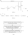
- FIG. 2 is a flowchart illustrating a method of transmitting synchronization signal blocks according to an example. As shown in FIG. 2 , the method includes: In step 11, target mode index information is determined according to a preset synchronization information block burst set (i.e. SS burst set) mode.
- a preset synchronization information block burst set i.e. SS burst set
- a plurality of SS burst set modes are available to the base station for broadcasting synchronization information blocks.
- configuration information corresponding to each SS burst set mode varies.
- the basic information of an SS burst set includes: a duration of the SS burst set T0, a number of bursts included, and an SS burst transmission period T1.
- the configuration information of an SS burst set mode mainly includes: burst types, burst numbers of each type, and positional relationship between bursts.
- FIG. 3 is a schematic diagram illustrating structures of six SS burst set modes according to an example.
- a base station may use one of the modes as shown in FIG. 3 to broadcast synchronization information blocks according to actual needs.
- Mode 1 indicates that the base station performs four times of synchronization signal sweeping on a target cell by using SS block beams with the same frequency band within one duration of an SS burst set, for example 20 ms. In other words, within 20 ms, a stationary piece of UE in the cell is swept by the SS block beams at four different moments, where time difference between each two adjacent moments is 5 ms.
- Mode 2 and Mode 3 indicate that the base station performs two times of synchronization signal sweeping on a target cell by using beams with the same frequency band within one duration of an SS burst set. In other words, within 20 ms, a stationary piece of UE in the cell is covered by SS block beams at two different moments, where the two moments are separated by 10 ms.
- the Burst 0 in Mode 2 and Mode 3 indicates that, in its corresponding time period, no SS block is configured in a sweep beam of the base station, and such a burst may be referred to as an invalid burst.
- Mode 2 differs from Mode 3 in that the valid bursts, i.e., Burst Is, and the invalid bursts are positioned differently in time domain.
- Mode 4 indicates that, within one duration of an SS burst set, SS block beams with two different frequency bands are used to perform two times of synchronization signal sweeping on a target cell. Take a 6 GHz frequency band and an 8 GHz frequency band as examples.
- Mode 4 indicates: the base station sweeps the target cell (performs one time of synchronization signal sweeping) by using the SS block beams with the 6 GHz frequency band, which corresponds to Burst 1; and then, after an interval T1 of, for example, 5 ms, the base station sweeps the target cell by using the SS block beams with the 8 GHz frequency band, which corresponds to Burst 2. Then, a sweep with Burst 1 starts after another 5 ms, and a sweep with Burst 2 starts after yet another 5 ms. Each Burst 1 and Burst 2 constitute a combination which occupies half of one duration of the SS burst set, that is 10 ms.
- a stationary piece of UE with a working frequency band of 6 GHz in the cell is covered at two different moments, each by one of the SS block beams in Burst 1, where the two moments are separated by 10 ms.
- a stationary piece of UE with a working frequency band of 8 GHz in the cell is covered at two different moments, each by one of the SS block beams in Burst 2, where the two moments are separated by 10 ms.
- Mode 5 indicates that, within one duration of the SS burst set, SS block beams with four different frequency bands are used to perform synchronization signal sweeping on a target cell.
- the base station performs one time of synchronization signal sweeping on the target cell by using the SS block beams with every frequency band.
- Mode 6 indicates that, within one duration of an SS burst set, SS block beams with one frequency band are used to perform one time of synchronization signal sweeping on a target cell. Similarly, a stationary piece of UE in the cell working in a corresponding frequency band, is swept only once by the SS block beam.
- each mode may be represented by mode index information of a preset format and size.
- a list of index information may be used to record the correspondence between the types of the SS burst set mode and the mode index information. For example, as shown in Table 1: Table 1 Mode Mode 1 Mode 2 Mode 3 Mode 4 Mode 5 Mode 6 ... Mode index information 4/4 2/4 2/4 2/2 1/1 1/4 ...
- Table 1 records the mode index information corresponding to each SS burst set mode shown in FIG. 3 .
- FIG. 4 is a flowchart illustrating another method of transmitting synchronization information blocks according to an example. As shown in FIG. 4 , the foregoing step 11 includes:
- step 111 a pre-configured index information list is queried according to a preset SS burst set mode, and mode index information corresponding to the preset SS burst set mode is obtained.
- the base station is to transmit synchronization information blocks to a target cell by using the SS burst set corresponding to Mode 1 as shown in FIG. 3 . Then, by querying the Table 1 with the mode (Mode 1), the corresponding mode index information is determined as 4/ 4.
- step 12 the target mode index information is stored in each synchronization information block, and target synchronization information blocks to be transmitted are acquired.
- the base station in each synchronization information block, stores the mode index information corresponding to the SS burst set mode currently used by the base station, so that the UE is informed which mode of the SS burst set is currently used for synchronization signal transmission.
- the mode index information determined by the base station has a small amount of data, and can be fully represented by only a few bits. As shown in Table 1, the mode index information, for example 4/4, can be fully represented by only 3 bits, which effectively saves radio transmission resources.
- storing the target mode index information in each SS block and acquiring the target SS blocks are performed in the following manners.
- the target mode index information is stored in a physical broadcast channel (PBCH) of each synchronization information block in the SS burst set of a preset mode.
- PBCH physical broadcast channel
- the PBCH serves to transmit important parameters of a cell, such as an MIB (Master Information Block) information used for system information configuration, and has the highest priority. Therefore, by adopting this manner, the UE may quickly acquire the synchronization information blocks, the priority of acquiring the synchronization information blocks is improved, and further, the efficiency of acquiring the synchronization information blocks is boosted.
- MIB Master Information Block
- a base station may store the target mode index information in a specified field of the PBCH, for example the 10th to 12th bits, so that the UE can quickly acquire the target mode index information, and the efficiency of acquiring the synchronization information blocks is further boosted.
- the target mode index information is stored in other channels of each synchronization information block in the SS burst set of a preset mode.
- a base station may also store target mode index information in other channels, for example, the physical channel used for dynamically broadcasting cell information such as various SIBs (System Information Blocks), DBCH.
- SIBs System Information Blocks
- a base station may also store the target mode index information in a specified location of other channels, so that the UE can quickly find the synchronization information block. The process will not be described here.
- step 13 the target synchronization information blocks are periodically transmitted to UE in a target cell by using high frequency beams.
- the base station After generating the target SS block, the base station loads the SS blocks in every high-frequency beam of valid bursts, which are contained in the SS burst set of a preset mode, so that SS block beams are formed. Then the base station performs synchronization signal sweeping on the target cell by using the SS block beams.
- the transmission process of the target synchronization information blocks is described below with reference to a specific example. It is assumed that a base station determines that Mode 5 in FIG. 3 is to be used as the SS burst set mode for transmitting synchronization information blocks to UE in a target cell.
- the transmission process is as follows.
- the burst shown in FIG. 1-2 is Burst 1 in Mode 5.
- the base station When transmitting the first burst to the target cell, the base station first loads the mode index information of Mode 5, i.e. 1/1, into a synchronization information block and obtains block 1 shown in FIG. 1-2 . Then, the base station transmits the high frequency beam with a corresponding frequency band, such as 6 GHz, as beam 1 shown in FIG. 1-1 , in a certain direction and a preset transmission angle to the target cell, so that the UE within the coverage area corresponding to the target cell, for example UE1, can acquire the SS block 1.
- a corresponding frequency band such as 6 GHz
- all blocks starting from block 2 to block n are obtained according to the above method, and transmitted sequentially to the target cell by using the high frequency beams corresponding to the frequency band such as 6 GHz, so that all areas of the target cell are covered by the SS block beams.
- the high frequency beams with another frequency band are used to transmit Burst 2 in Mode 5 shown in FIG. 3 , and so on.
- Burst 4 is transmitted, which signifies the transmission of a complete SS burst set as shown in FIG. 1-4 .
- the UE can accurately calculate when to receive the synchronization signal, thereby quickly and accurately acquiring the required synchronization information blocks.
- increased device power consumption and influenced device efficiency which are caused by blind detection may be avoided.
- FIG. 5 is a flowchart illustrating another method of transmitting synchronization information blocks according to an example. On the basis of the example as shown in FIG.2 , before step 11, the method further includes:
- step 10 a mode of the SS burst set to be transmitted is determined according to target cell information.
- a base station may cover several cells, for example 3 cells.
- the distribution of UE in each cell may be identical or different. If the UE in each cell are distributed similarly or identically, the base station may use the SS burst set in the same mode for transmitting synchronization information blocks to every cell.
- the base station may first select a mode of SS burst set appropriate for the target cell according to target cell information.
- FIG. 6 is a flowchart illustrating another method of transmitting synchronization information blocks according to an example. As shown in FIG. 6 , the step 10 includes:
- the cell information of a target cell includes at least one of the following: an identifier of the cell, a UE type in the cell, and service busyness of the cell.
- the implementations of the step 102 may include, but are not limited to, the following situations.
- the mode of SS burst set is determined according to the identifier of the target cell. It is assumed that the target cell information consists of the cell identifier only.
- the base station may predetermine a list of synchronization modes according to the type of each cell. It is assumed that cells fall into two types: a cell for dedicated devices and a normal cell. During initialization, the base station designates modes of SS burst set for each cell identifier according to the cell types. Again, it is assumed that the base station covers 3 cells. The 3 cells are referred to as cell A, cell B, and cell C.
- the cells A and B are normal cells, that is, communication with UE of various frequency bands is to be satisfied; and if the cell C is a cell for dedicated devices, for example for specific requirements such as security requirements, the cell only allows communication with UE of a certain frequency band, for example 6G, and denies access from UE of other working frequency bands.
- the preset synchronization mode list is as shown in Table 2: Table 2 Cell identifier A B C SS burst set mode Mode 5 Mode 5 Mode 1, 2, 3, or 6
- the base station may use the SS burst set as represented by Mode 5 of FIG. 3 to send SS blocks to the UE in cell A.
- the mode of SS burst set is determined according to the UE type in the target cell.
- the target cell information includes at least the type of UE which the cell allows access from.
- the base station After determining the target cell identifier, the base station queries cell's history information record and finds that, within a certain period of time, for example the first quarter of the year, UE with only two frequency bands is accessed to the cell. On the basis of the above information, the base station may adopt the SS burst set as represented by Mode 4 of FIG. 3 to broadcast SS blocks to the UE in the target cell in the first quarter of the year.
- the mode of SS burst set is determined according to the service busyness of the target cell.
- the target cell only allows access from UE with one frequency band.
- the base station queries cell's history information record to determine service busyness of the target cell in each time period, and then adopts different modes of SS burst set.
- the target cell C may transmit SS blocks using Mode 1, 2, 3 or 6. It is assumed that, according to historical statistics, the service busyness of the cell C is highest during 8:00 to 12:00, moderate during 12:00 to 22:00, and lowest during 22:00 ⁇ 8:00.
- the base station can transmit SS blocks in different SS burst set modes in different time periods, as shown in Table 3: Table 3 Time period Service busyness Mode 8:00-12:00 High Mode 1 12:00-22:00 Moderate Mode 2 or 3 22:00-8:00 Low Mode 6 As shown in Table 3, the base station uses an appropriate mode of SS burst set to transmit the SS blocks according to the service busyness of the cell. In this way, the radio resources occupied by synchronization information blocks are effectively saved, the radio resources are more efficiently utilized, and the power consumption of the base station is reduced.
- the present disclosure also provides a method of acquiring synchronization information blocks, which is applied to UE.
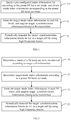
- FIG. 7 is a flowchart illustrating a method of acquiring synchronization information blocks according to an example. As shown in FIG. 7 , the method includes the following steps.
- step 21 a synchronization information block carried by a high frequency beam is detected according to a preset initial detection window.
- the UE After entering the target cell, the UE enables a preset initial detection window with a duration of, for example, 5 ms, to perform a blind detection for the synchronization information blocks, so that the first synchronization information block is quickly detected.
- the width of the initial detection window is generally determined according to a number of bursts with different frequency bands included in one SS burst set, that is, the SS burst set as represented by the Mode 5 in FIG. 3 is used to determine the initial detection window.
- the duration T0 of a SS burst set is 20 ms.
- the SS burst set as represented by Mode 5 includes four bursts. Therefore, the width of the initial detection window can be determined as 5 ms.
- the window can be slightly larger than 5 ms and can be represented by 5 ms+.
- step 22 mode index information of the SS burst set is acquired from the detected synchronization information block.
- the mode index information is carried in every SS block in an SS burst set of a mode transmitted by the base station.
- the UE may analyze the mode index information of the SS burst set from a preset location of the synchronization information block, for example the PBCH or other channels, or a specified field of the above preset channel.
- At least two manners may be adopted for acquiring the mode index information of the SS burst set from the synchronization information block.
- the UE After detecting the first synchronization information block, the UE acquires the mode index information of the SS burst set from the first SS block according to a preset mode index information storage protocol.
- FIG. 8 is a flowchart illustrating another method of acquiring synchronization information blocks according to an example. As shown in FIG. 8 , the foregoing step 22 includes the following steps.
- step 221 a piece of mode index information is analyzed from each of a preset quantity of the detected synchronization information blocks.
- the UE may continuously acquire a preset number, for example 4, of synchronization information blocks, and acquire a piece of mode index information of the SS burst set from each synchronization information block.
- step 222 identical pieces of mode index information among the preset quantity of the mode index information are determined as valid mode index information.
- a total of four pieces of mode index information are acquired through the step 221.
- the four pieces of the mode index information are identical, but errors may occur during decoding by the UE, for example the mode index information 2/4 is analyzed into 4/4. Consequently, an inaccurate prediction of arrival times of subsequent synchronization information blocks may arise from the analyzing error.
- identical pieces of mode index information among the preset quantity of mode index information after analyzing are determined as valid mode index information. In this way, the accuracy of mode index information is improved.
- step 23 expected arrival times of subsequent synchronization information blocks are determined according to the mode index information.
- the mode index information may be determined by the UE either in the first manner or in the second manner.
- FIG. 9 is a flowchart illustrating another method of acquiring synchronization information blocks according to an example. As shown in FIG. 9 , the foregoing step 23 includes the following steps.
- step 231 a time interval between two adjacent synchronization information blocks is determined according to the mode index information.
- the UE may calculate the time interval between two adjacent SS blocks, that is, the time interval between two adjacent and identical SS bursts.
- the time interval between two adjacent and identical SS bursts is determined as 20 ms.
- the mode index information is 4/4, which corresponds to the SS burst set as represented by Mode 1 in FIG. 3
- the time interval between two adjacent and identical SS bursts is 5 ms.
- T2 the time interval between two adjacent and identical SS bursts
- the correspondence among the mode index information, SS burst set mode, and T2 can be listed, for example, as the following Table 4: Table 4 Mode Mode 1 Mode 2 Mode 3 Mode 4 Mode 5 Mode 6 Mode index information 4/4 2/4 2/4 2/2 1/1 1/4 T2 5 ms 10 ms 10 ms 10 ms 20 ms 20 ms
- step 232 expected arrival times of subsequent synchronization information blocks are determined according to reception time of a current synchronization information block and the time interval of two adjacent synchronization information blocks.
- UE 1 detects a first synchronization information block, for example block 2 as shown in FIG. 1-2 , and the analyzed mode index information 2/4 therefrom. It is known by querying the Table 4 that, in this mode, the time interval between the arrivals of two adjacent blocks 2 at UE 1 is 10 ms. In other words, UE 1 may detect the second synchronization information block, i.e., block 2, through the detection window at time t1 + 10 ms. Accordingly, the times when subsequent block 2s arrive at UE 1 are calculated.
- step 24 during subsequent signal synchronization processes, target synchronization information blocks are acquired according to the expected arrival times.
- the UE does not enable the detection window every time when a synchronization information block arrives. Instead, the UE performs signal synchronization with a preset strategy of, for example, one detection after every two synchronization information blocks.
- the UE may calculate opening times of the detection window according to the above information. Still taking the above-mentioned UE 1 as an example. It is assumed that the UE 1 adopts a strategy of one detection after every two synchronization information blocks. After detecting the first synchronization information block at time t1, the UE 1 can enable a synchronization signal detection window of a preset width which centering on the time t1 + 30 ms to detect next target synchronization information block. Similarly, the opening times of the detection window are determined according to the estimated arrival times of the target synchronization information blocks, in order to sequentially detect the target synchronization information blocks.
- the UE By using the method of acquiring synchronization information blocks provided in the examples of the present disclosure, the UE first acquires the mode index information from the detected synchronization information block, so that the UE determines the mode of SS burst set adopted by the base station for broadcasting synchronization information in the cell. Then, the time interval between every two adjacent synchronization information blocks is calculated, and the reception times of subsequent synchronization information blocks are estimated. In this way, the use of blind detection for the synchronization signal detection is avoided, radio resources of the UE are effectively saved, and the power consumption of the UE is reduced.
- the present disclosure also provides apparatus examples implemented by applying functions and examples of corresponding terminals.
- FIG. 10 is a block diagram illustrating an apparatus for transmitting synchronization information blocks according to an example. Applied to a base station, the apparatus may include:
- FIG. 11 is a block diagram illustrating another apparatus for transmitting synchronization information blocks according to an example.
- the mode index determining module 31 may comprise: a mode index determining sub-module 311, configured to query a pre-configured index information list according to the preset SS burst set mode to acquire mode index information corresponding to the preset SS burst set mode.
- FIG. 12 is a block diagram illustrating another apparatus for transmitting synchronization information blocks according to an example.
- the storing module 32 may comprise one of the following sub-modules:
- FIG. 13 is a block diagram illustrating another apparatus for transmitting synchronization information blocks according to an example. Based on the example as shown in FIG. 10 , the apparatus may further include: a mode determining module 30, configured to determine a mode of a SS burst set to be transmitted according to target cell information.
- a mode determining module 30 configured to determine a mode of a SS burst set to be transmitted according to target cell information.
- FIG. 14 is a block diagram illustrating another apparatus for transmitting synchronization information blocks according to an example. Based on the example as shown in FIG. 13 , the mode determining module 30 may include:
- the present disclosure also provides an apparatus for acquiring synchronization information blocks applied to UE.
- FIG. 15 is a block diagram illustrating an apparatus for acquiring synchronization information blocks according to an example.
- the apparatus may include:
- FIG. 16 is a block diagram illustrating another apparatus for acquiring synchronization information blocks according to an example.
- the index information acquiring module 42 may include: a first acquiring sub-module 421, configured to acquire, after detecting a first synchronization information block, the mode index information of the SS burst set from the synchronization information block.
- FIG. 17 is a block diagram illustrating another apparatus for acquiring synchronization information blocks according to an example. Based on the example as shown in FIG. 15 , the index information acquiring module 42 may include:
- FIG. 18 is a block diagram illustrating another apparatus for acquiring synchronization information blocks according to an example.
- the time predicting module 43 may include:
- the present disclosure provides an apparatus for transmitting synchronization information blocks, including: a processor; a memory for storing processor executable instructions; where the processor is configured to:
- the present disclosure provides an apparatus for acquiring synchronization information blocks, including: a processor; a memory for storing processor executable instructions; where the processor is configured to:
- FIG. 19 is a schematic diagram illustrating a structure of an apparatus 1900 for transmitting synchronization information blocks according to an example.
- the apparatus 1900 can be provided as a base station.
- the apparatus 1900 includes a processing component 1922, a wireless transmitting/receiving component 1924, an antenna component 1926 and a signal processing component specific to a wireless interface.
- the processing component 1922 may further include one or more processors.
- One of the processors of the processing component 1922 is configured to:
- FIG. 20 is a schematic diagram illustrating a structure of an apparatus 2000 for acquiring synchronization information blocks according to an example.
- the apparatus 2000 may be UE, and may be specified as, for example, a mobile phone, a computer, a digital broadcasting terminal, a message receiving and transmitting device, a game console, a tablet device, a medical device, a fitness device, a personal digital assistant, a wearable device such as a smart watch, smart glasses, a smart bracelet, smart running shoes, etc.
- the apparatus 2000 may include one or more of the following components: a processing component 2002, a memory 2004, a power supply component 2006, a multimedia component 2008, an audio component 2010, an input/output (I/O) interface 2012, a sensor component 2014 and a communication component 2016.
- a processing component 2002 a memory 2004, a power supply component 2006, a multimedia component 2008, an audio component 2010, an input/output (I/O) interface 2012, a sensor component 2014 and a communication component 2016.
- the processing component 2002 generally controls overall operations of the apparatus 2000, such as operations associated with display, phone calls, data communications, camera operations, and recording operations.
- the processing component 2002 may include one or more processors 2020 to execute instructions to complete all or part of the steps of the above methods.
- the processing component 2002 may include one or more modules which facilitate the interaction between the processing component 2002 and other components.
- the processing component 2002 may include a multimedia module to facilitate the interaction between the multimedia component 2008 and the processing component 2002.
- the memory 2004 is to store various types of data to support the operation of the apparatus 2000. Examples of such data include instructions for any application or method operated on the apparatus 2000, contact data, phonebook data, messages, pictures, videos, and so on.
- the memory 2004 may be implemented by any type of volatile or non-volatile storage devices or a combination thereof, such as a Static Random Access Memory (SRAM), an Electrically Erasable Programmable Read-Only Memory (EEPROM), an Erasable Programmable Read-Only Memory (EPROM), a Programmable Read-Only Memory (PROM), a Read-Only Memory (ROM), a magnetic memory, a flash memory, a magnetic or optical disk.
- SRAM Static Random Access Memory
- EEPROM Electrically Erasable Programmable Read-Only Memory
- EPROM Erasable Programmable Read-Only Memory
- PROM Programmable Read-Only Memory
- ROM Read-Only Memory
- the power supply component 2006 provides power to different components of the apparatus 2000.
- the power supply component 2006 may include a power management system, one or more power supplies, and other components associated with generating, managing, and distributing power for the apparatus 2000.
- the multimedia component 2008 includes a screen providing an output interface between the apparatus 2000 and a user.
- the screen may include a Liquid Crystal Display (LCD) and a Touch Panel (TP). If the screen includes the TP, the screen may be implemented as a touch screen to receive input signals from the user.
- the TP may include one or more touch sensors to sense touches, swipes, and gestures on the TP. The touch sensors may not only sense a boundary of a touch or swipe, but also sense a duration and a pressure associated with the touch or swipe.
- the multimedia component 2008 may include a front camera and/or a rear camera. The front camera and/or rear camera may receive external multimedia data when the apparatus 2000 is in an operating mode, such as a photographing mode or a video mode. Each of the front camera and the rear camera may be a fixed optical lens system or have focal length and optical zooming capability.
- the audio component 2010 is to output and/or input an audio signal.
- the audio component 2010 includes a microphone (MIC).
- the MIC When the apparatus 2000 is in an operating mode, such as a call mode, a recording mode, and a voice recognition mode, the MIC is to receive an external audio signal.
- the received audio signal may be further stored in the memory 2004 or sent via the communication component 2016.
- the audio component 2010 further includes a speaker to output an audio signal.
- the I/O interface 2012 may provide an interface between the processing component 2002 and peripheral interface modules.
- peripheral interface modules may include a keyboard, a click wheel, buttons and so on. These buttons may include, but are not limited to, a home button, a volume button, a starting button and a locking button.
- the sensor component 2014 includes one or more sensors to provide status assessments of various aspects for the apparatus 2000.
- the sensor component 2014 may detect the on/off status of the apparatus 2000, and relative positioning of component, for example, the component is a display and a keypad of the apparatus 2000.
- the sensor component 2014 may also detect a change in position of the apparatus 2000 or a component of the apparatus 2000, a presence or absence of the contact between a user and the apparatus 2000, an orientation or an acceleration/deceleration of the apparatus 2000, and a change in temperature of the apparatus 2000.
- the sensor component 2014 may include a proximity sensor to detect the presence of a nearby object without any physical contact.
- the sensor component 2014 may further include an optical sensor, such as a Complementary Metal-Oxide-Semiconductor (CMOS) or Charged Coupled Device (CCD) image sensor which is used in imaging applications.
- CMOS Complementary Metal-Oxide-Semiconductor
- CCD Charged Coupled Device
- the sensor component 2014 may further include an acceleration sensor, a gyroscope sensor, a magnetic sensor, a pressure sensor, or a temperature sensor.
- the communication component 2016 is to facilitate wired or wireless communication between the apparatus 2000 and other devices.
- the apparatus 2000 may access a wireless network that is based on a communication standard, such as Wi-Fi, 2G or 3G, or a combination thereof.
- the communication component 2016 receives a broadcast signal or broadcast-associated information from an external broadcast management system via a broadcast channel.
- the communication component 2016 further includes a Near Field Communication (NFC) module to facilitate short-range communications.
- the NFC module may be implemented based on a Radio Frequency Identification (RFID) technology, an Infrared Data Association (IrDA) technology, an Ultra Wideband (UWB) technology, a Bluetooth® (BT) technology and other technologies.
- RFID Radio Frequency Identification
- IrDA Infrared Data Association
- UWB Ultra Wideband
- BT Bluetooth®
- the apparatus 2000 may be implemented by one or more Application Specific Integrated Circuits (ASICs), Digital Signal Processors (DSPs), Digital Signal Processing Devices (DSPDs), programmable Logic Devices (PLDs), Field Programmable Gate Arrays (FPGAs), controllers, microcontrollers, microprocessors, or other electronic components for performing the above methods.
- ASICs Application Specific Integrated Circuits
- DSPs Digital Signal Processors
- DSPDs Digital Signal Processing Devices
- PLDs programmable Logic Devices
- FPGAs Field Programmable Gate Arrays
- controllers microcontrollers, microprocessors, or other electronic components for performing the above methods.
- non-transitory computer-readable storage medium including instructions, such as a memory 2004 including instructions executable by the processor 2020 of the apparatus 2000 to perform the acquisition of synchronization information blocks.
- the non-volatile computer-readable storage medium is a ROM, a random access memory (RAM), a CD-ROM, a magnetic tape, a floppy disk, or an optical data storage device.
Landscapes
- Engineering & Computer Science (AREA)
- Computer Networks & Wireless Communication (AREA)
- Signal Processing (AREA)
- Computer Security & Cryptography (AREA)
- Mobile Radio Communication Systems (AREA)
Abstract
Description
- The present disclosure relates to the field of communications technology, and in particular, to a method and an apparatus for transmitting and acquiring synchronization information blocks.
- Prior to requesting access to a cell of a network, user equipment (UE) needs to receive primary and secondary synchronization signals sent by a base station to perform signal synchronization. After the synchronization succeeds, the UE further receives and analyze system information of the cell sent by the base station to perform system configuration, as preparations for a random access to the network.
- In a long-term evolution (LTE) network communication system of the related art, the base station transmits the synchronization signal with a fixed period. After the first synchronization succeeds, the UE estimates the reception time of subsequent synchronization signals on the basis of the fixed transmission period of the synchronization signal, thereby accurately performing the signal synchronization.
- However, in a 5G network communication system, the design of the synchronization signal has not been determined, or in other words, the mode in which the base station transmits synchronization signals in 5G network may not be fixed, and the UE cannot quickly and accurately detect the synchronization signal.
- In order to overcome the problems in the related art, examples of the present disclosure provide a method and an apparatus for transmitting and acquiring synchronization information blocks, such that UE in 5G network performs signal synchronization quickly and accurately.
- According to a first aspect of the examples of the present disclosure, a method of transmitting synchronization signal blocks is provided, which applied to a base station and including:
- determining target mode index information according to a preset synchronization information block burst set (SS burst set) mode;
- storing the target mode index information in each synchronization information block (SS block) to acquire target synchronization information blocks to be transmitted; and
- periodically transmitting the target synchronization information blocks to user equipment in a target cell using high frequency beams;
- where each of the SS burst sets includes a first preset number of synchronization signal bursts (SS bursts) that are periodically transmitted; and each of the SS bursts includes a second preset number of the target synchronization information blocks that are transmitted in a spatial sequence.
- Optionally, determining the target mode index information according to the preset SS burst set mode includes:
querying a pre-configured index information list according to the preset SS burst set mode to acquire mode index information corresponding to the preset SS burst set mode. - Optionally, storing the target mode index information in each synchronization information block (SS block) to acquire the target synchronization information blocks are performed in any of the following manners:
- storing the target mode index information in a physical broadcast channel (PBCH) of each synchronization information block in the SS burst set of the preset mode;
- storing the target mode index information in other channels of each synchronization information block in the SS burst set of the preset mode; and
- storing the target mode index information in a designated position of the PBCH of each synchronization information block in the SS burst set of the preset mode.
- Optionally, before determining the target mode index information according to the preset SS burst set mode, the method further includes:
determining a mode of a SS burst set to be transmitted according to target cell information. - Optionally, determining the mode of the SS burst set to be transmitted according to the target cell information includes:
- acquiring the target cell information, where the target cell information includes at least one of the following: an identifier of the cell, a user equipment type in the cell, and service busyness of the cell; and
- determining the mode of SS burst set suitable for the target cell according to the target cell information.
- According to a second aspect of the examples of the present disclosure, a method of acquiring synchronization information blocks is provided, which applied to UE and including:
- detecting a synchronization information block carried by a high frequency beam according to a preset initial detection window;
- acquiring mode index information of an SS burst set from the detected synchronization information block;
- determining expected arrival times of subsequent synchronization information blocks according to the mode index information; and
- during subsequent signal synchronization processes, acquiring target synchronization information blocks according to the expected arrival times.
- Optionally, acquiring the mode index information of the SS burst set from the detected synchronization information block includes:
after detecting a first synchronization information block, acquiring the mode index information of the SS burst set from the synchronization information block. - Optionally, acquiring the mode index information of the SS burst set from the detected synchronization information block includes:
- analyzing a piece of the mode index information from each of a preset quantity of the detected synchronization information blocks; and
- determining identical pieces of the mode index information among the preset quantity of the mode index information as valid mode index information.
- Optionally, determining the expected arrival times of the subsequent synchronization information blocks according to the mode index information includes:
- determining a time interval of two adjacent synchronization information blocks according to the mode index information; and
- determining the expected arrival times of the subsequent synchronization information blocks according to a reception time of current synchronization information block and the time interval of two adjacent synchronization information blocks.
- According to a third aspect of the examples of the present disclosure, an apparatus for transmitting synchronization information blocks is provided, which applied to a base station and including:
- a mode index determining module, configured to d target mode index information according to a preset SS burst set mode;
- a storing module, configured to store the target mode index information in each SS block to acquire target synchronization information blocks to be transmitted; and
- a transmitting module, configured to periodically transmit the target synchronization information blocks to user equipment in a target cell using high frequency beams;
- where each of the SS burst sets includes a first preset number of SS bursts that are periodically transmitted; and each of the SS bursts includes a second preset number of the target synchronization information blocks that are transmitted in a spatial sequence.
- Optionally, the mode index determining module includes:
a mode index determining sub-module, configured to query a pre-configured index information list according to the preset SS burst set mode to acquire mode index information corresponding to the preset SS burst set mode. - Optionally, the storing module includes any one of the following sub-modules:
- a first storing sub-module, configured to store the target mode index information in a PBCH of each synchronization information block in the SS burst set of the preset mode;
- a second storing sub-module, configured to store the target mode index information in other channels of each synchronization information block in the SS burst set of the preset mode; and
- a third storing sub-module, configured to store the target mode index information in a designated position of the PBCH of each synchronization information block in the SS burst set of the preset mode.
- Optionally, the apparatus for transmitting synchronization information blocks further includes:
a mode determining module, configured to determine a mode of a SS burst set to be transmitted according to target cell information. - Optionally, the mode determining module includes:
- a cell information acquiring sub-module, configured to acquire the target cell information, where the target cell information includes at least one of the following: an identifier of the cell, a user equipment type in the cell, and service busyness of the cell; and
- a mode determining sub-module, configured to determine the mode of SS burst set suitable for the target cell according to the target cell information.
- According to a fourth aspect of the examples of the present disclosure, an apparatus for acquiring synchronization information blocks is provided, which applied to UE and including:
- an initial detecting module, configured to detect a synchronization information block carried by a high frequency beam according to a preset initial detection window;
- an index information acquiring module, configured to acquire mode index information of an SS burst set from the detected synchronization information block;
- a time predicting module, configured to determine expected arrival times of subsequent synchronization information blocks according to the mode index information; and
- a synchronization signal acquiring module, configured to acquire, during subsequent signal synchronization processes, target synchronization information blocks according to the expected arrival times.
- Optionally, the index information acquiring module includes:
a first acquiring sub-module, configured to acquire, after detecting a first synchronization information block, the mode index information of the SS burst set from the synchronization information block. - Optionally, the index information acquiring module includes:
- a synchronization block acquiring sub-module, configured to analyze a piece of the mode index information from each of a preset quantity of the detected synchronization information blocks; and
- a second acquiring sub-module, configured to determine identical pieces of the mode index information among the preset quantity of the mode index information as valid mode index information.
- Optionally, the time predicting module includes:
- a time interval determining sub-module, configured to determine a time interval of two adjacent synchronization information blocks according to the mode index information; and
- a time pre-calculating sub-module, configured to determine the expected arrival times of the subsequent synchronization information blocks according to a reception time of current synchronization information block and the time interval of two adjacent synchronization information blocks.
- According to a fifth aspect of the examples of the present disclosure, an apparatus for transmitting synchronization information blocks is provided, including: a processor; a memory for storing processor executable instructions; where the processor is configured to:
- determine target mode index information according to a preset SS burst set mode;
- store the target mode index information in each SS block to acquire target synchronization information blocks to be transmitted; and
- periodically transmit the target synchronization information blocks to user equipment in a target cell using high frequency beams;
- where each of the SS burst sets includes a first preset number of SS bursts that are periodically transmitted; and each of the SS bursts includes a second preset number of the target synchronization information blocks that are transmitted in a spatial sequence.
- According to a sixth aspect of the examples of the present disclosure, an apparatus for acquiring synchronization information blocks is provided, including: a processor; a memory for storing processor executable instructions; where the processor is configured to:
- detect a synchronization information block carried by a high frequency beam according to a preset initial detection window;
- acquire mode index information of an SS burst set from the detected synchronization information block;
- determine expected arrival times of subsequent synchronization information blocks according to the mode index information; and
- acquire, during subsequent signal synchronization processes, target synchronization information blocks according to the expected arrival times.
- The technical solutions provided by the examples of the present disclosure may include the following beneficial effects.
- In the present disclosure, when broadcasting synchronization information blocks to UE in a target cell, a base station in 5G network stores in every synchronization information block the mode index information corresponding to an SS burst set mode which the base station adopts. The base station broadcasts synchronization signals to the UE with high frequency beams carrying target synchronization information blocks. After acquiring a synchronization information block, the UE in the cell acquires the mode index information from the synchronization information block, learns the manner in which the base station broadcasts synchronization information blocks, and then accurately calculates expected arrival times of subsequent synchronization information blocks. In this way, in subsequent processes of signal synchronization with the cell, the UE is only required to open the synchronization signal detection window to acquire the target synchronization information blocks according to the expected arrival times, which not only makes the acquisition of the synchronization information blocks quick and accurate, but also reduces the power consumption of the equipment.
- In the present disclosure, after determining a preset SS burst set mode for a target cell, the base station queries a pre-configured list of index information by using the mode of the preset SS burst set, and acquires the mode index information corresponding to the preset SS burst set mode. By querying a list, the mode index information is quickly acquired.
- In the present disclosure, the base station can store the mode index information in a PBCH or other channels of each synchronization information block, or a designated position thereof, so that the UE can quickly acquire the mode index information according to the mode information storage protocol, thereby improving the signal synchronization efficiency of the UE.
- In the present disclosure, when a cell requests signal coverage of a base station, the base station can first determine a suitable mode of an SS burst set to be transmitted to the target cell according to cell information of the target cell, thereby effectively utilizing radio resources.
- In the present disclosure, when choosing the mode of the SS burst set to be transmitted to the target cell, the base station can take into account comprehensively an identifier of the cell, UE type(s) in the cell, service busyness of the cell, and the like. Then the base station can choose the one most appropriate for the target cell, so that radio resources are effectively utilized, waste of resources is avoided, and the power consumption of the base station is reduced.
- The above general description and the following detailed description are intended to be illustrative and explanatory, and not to be limiting of the present disclosure.
- The accompanying drawings, incorporated in and constitute part of the specification, illustrate examples of the present disclosure, and serve to explain the principles of the present disclosure in conjunction with the specification.
-
FIG. 1-1 is a schematic diagram illustrating high frequency beam sweeping in a 5G system according to an example of the present disclosure. -
FIG. 1-2 is a schematic diagram illustrating a structure of an SS burst according to an example of the present disclosure. -
FIG. 1-3 is a schematic diagram illustrating a structure of an SS burst set according to an example of the present disclosure. -
FIG. 1-4 is a schematic diagram illustrating transmission of an SS burst set according to an example of the present disclosure. -
FIG. 2 is a flowchart illustrating a method of transmitting synchronization signal blocks according to an example of the present disclosure. -
FIG. 3 is a schematic diagram illustrating structures of six SS burst set modes according to an example of the present disclosure. -
FIG. 4 is a flowchart illustrating another method of transmitting synchronization information blocks according to an example of the present disclosure. -
FIG. 5 is a flowchart illustrating another method of transmitting synchronization information blocks according to an example of the present disclosure. -
FIG. 6 is a flowchart illustrating another method of transmitting synchronization information blocks according to an example of the present disclosure. -
FIG. 7 is a flowchart illustrating a method of acquiring synchronization information blocks according to an example of the present disclosure. -
FIG. 8 is a flowchart illustrating another method of acquiring synchronization information blocks according to an example of the present disclosure. -
FIG. 9 is a flowchart illustrating another method of acquiring synchronization information blocks according to an example of the present disclosure. -
FIG. 10 is a block diagram illustrating an apparatus for transmitting synchronization information blocks according to an example of the present disclosure. -
FIG. 11 is a block diagram illustrating another apparatus for transmitting synchronization information blocks according to an example of the present disclosure. -
FIG. 12 is a block diagram illustrating another apparatus for transmitting synchronization information blocks according to an example of the present disclosure. -
FIG. 13 is a block diagram illustrating another apparatus for transmitting synchronization information blocks according to an example of the present disclosure. -
FIG. 14 is a block diagram illustrating another apparatus for transmitting synchronization information blocks according to an example of the present disclosure. -
FIG. 15 is a block diagram illustrating an apparatus for acquiring synchronization information blocks according to an example of the present disclosure. -
FIG. 16 is a block diagram illustrating another apparatus for acquiring synchronization information blocks according to an example of the present disclosure. -
FIG. 17 is a block diagram illustrating another apparatus for acquiring synchronization information blocks according to an example of the present disclosure. -
FIG. 18 is a block diagram illustrating another apparatus for acquiring synchronization information blocks according to an example of the present disclosure. -
FIG. 19 is a schematic diagram illustrating a structure of an apparatus for transmitting synchronization information blocks according to an example of the present disclosure; -
FIG. 20 is a schematic diagram illustrating a structure of an apparatus for acquiring synchronization information blocks according to an example of the present disclosure. - Examples will be described in detail herein, with illustrations thereof represented in the drawings. When the following descriptions involve the drawings, like numerals in different drawings represent like or similar elements unless otherwise indicated. The embodiments described in the following examples do not represent all embodiments consistent with the present disclosure. Instead, they are merely examples of apparatuses and methods consistent with some aspects of the present disclosure as detailed in the appended claims.
- The terms used in the present disclosure are for the purpose of describing particular examples only, and are not intended to limit the present disclosure. Terms determined by "a", "the" and "said" in their singular forms in the present disclosure and the appended claims are also intended to include plurality, unless clearly indicated otherwise in the context. It should also be understood that the term "and/or" as used herein refers to and encompasses any and all possible combinations of one or more of the associated listed items.
- It is to be understood that although terms "first", "second", "third", etc. may be used in the present disclosure to describe various information, such information should not be limited to these terms. These terms are only used to distinguish one type of information from another within a category. For example, without departing from the scope of the present disclosure, first information may be referred as second information; and similarly, second information may also be referred as first information. Depending on the context, the word "if' as used herein may be interpreted as "when" or "upon" or "in response to determining".
- The technical solution provided by the present disclosure is applicable to 5G network, or any other network communication systems that uses high frequency beams for information transmission. The high frequency beam is, for example, a beam with a frequency point of 6 GHz or higher. The executive body involved in the present disclosure includes a transmitting end and a receiving end of the high frequency beam. The transmitting end of the high frequency beam can be a base station, a sub base station, or the like, provided with a large-scale antenna array. The receiving end of the high frequency beam is, for example, user equipment (UE) provided with a smart antenna array. The UE is, for example, a user terminal, a user node, a mobile terminal, or a tablet computer. In a specific implementation process, the base station and the UE are independent from and in contact with each other to jointly implement the technical solution provided by the present disclosure.
- Before introducing the technical solutions of the present disclosure, it is necessary to know a method of information transmission of an LTE system in 5G and several concepts around synchronization signal transmission related to the present disclosure.
- Standardization with 5G, i.e., new radio (NR) network is being carried out in the 3rd Generation Partnership Project (3GPP). One of the key technologies of the 5G network communication system is beamforming technology. When the base station NW (NetWork) broadcasts downlink synchronization signals and necessary system information, a method of beam sweeping is adopted in the 5G high-frequency system, in which a cell is fully covered by a quick sweep with concentrated power, as shown in
FIG. 1-1. FIG. 1-1 is a schematic diagram illustrates the high frequency beam sweeping in the 5G system according to an example. - In 5G system, regarding the transmission of the synchronization signal, three concepts are defined: synchronization information block (i.e., SS block), synchronization signal burst (i.e., SS burst), and synchronization signal burst set (i.e., SS burst set).
- An SS block includes a Primary Synchronization Signal (PSS) and a Secondary Synchronization Signal (SSS). The SS block is loaded into a high frequency beam to form an SS block beam. The base station uses SS block beams to perform beam sweeping on the UE in a cell covered by signals of the base station, and broadcasts synchronization information to the UE in the cell through a downlink. After receiving and analyzing the synchronization information block, the UE performs signal synchronization with the cell of a network to prepare itself for accessing the cell of the network.
- An SS burst refers to a preset quantity of SS block beams required to be transmitted sequentially and directionally by a base station, so that all UE with a certain working frequency band in a cell is swept by the SS block beams during a beam sweeping process.
FIG. 1-2 is a schematic diagram illustrating a structure of an SS burst according to an example. As shown inFIG. 1-2 , the SS burst can be seen as a group of the SS block beams, each of which carries one SS block. The quantity of the SS block beams included in one SS burst is related to a transmission angle of a single beam, that is, a coverage area of the single beam. Every SS block beam in an SS burst has the same frequency band. - In the 5G system, the SS burst is transmitted periodically, in other words, the base station does not transmit SS bursts continuously, but transmit an SS burst every preset interval. For example, after an SS burst transmission is completed, another SS burst transmission starts after a 5 ms interval is passed. In an example of the present disclosure, the interval between two adjacent SS bursts may be represented by SS burst transmission period T1, and then in the above example, T1 = 5 ms.
- Because a base station may need to implement that UE with different working frequency bands in a 5G system is all swept by SS block beams, a plurality of SS bursts are to be transmitted, according to the interval between every two adjacent SS bursts (also known as the SS burst transmission period T1), an SS burst set is determined, and the SS burst set corresponds a duration, which can be represented as T0. In other words, the duration of the SS burst set relates to the type(s) of frequency bands specified in the 5G system and the foregoing SS burst transmission period T1.
- It is assumed that the 5G system specifies four frequency bands: 6 GHz, 8 GHz, 10 GHz, and 50 GHz; and specifies the SS burst transmission period T1 in the SS burst set is 5 ms, that is, the interval between two adjacent SS bursts is 5 ms. In a case that the time spent during the transmission of an SS burst is neglected (compared to the SS burst transmission period T1, an SS burst is transmitted within a very short time, possibly a few micro second, which is negligible), the duration of an SS burst set is equivalent to four SS burst intervals, that is 20 ms.
FIG. 1-3 is a schematic diagram illustrating a structure of an SS burst set according to an example. As shown inFIG. 1-3 , under the SS burst set mode, the frequency bands ofBurst 1,Burst 2,Burst 3 andBurst 4 are different, each larger than its predecessor. - In 5G system, the SS burst set is transmitted periodically, as shown in
FIG. 1-4 . - On the basis of the above technical introduction, the present disclosure provides a method of transmitting synchronization signal blocks, which is applied to a base station.
-
FIG. 2 is a flowchart illustrating a method of transmitting synchronization signal blocks according to an example. As shown inFIG. 2 , the method includes:
Instep 11, target mode index information is determined according to a preset synchronization information block burst set (i.e. SS burst set) mode. - In an example of the present disclosure, a plurality of SS burst set modes are available to the base station for broadcasting synchronization information blocks. When basic information of an SS burst set is determined, configuration information corresponding to each SS burst set mode varies. The basic information of an SS burst set includes: a duration of the SS burst set T0, a number of bursts included, and an SS burst transmission period T1. The configuration information of an SS burst set mode mainly includes: burst types, burst numbers of each type, and positional relationship between bursts.
-
FIG. 3 is a schematic diagram illustrating structures of six SS burst set modes according to an example. A base station may use one of the modes as shown inFIG. 3 to broadcast synchronization information blocks according to actual needs. -
Mode 1 indicates that the base station performs four times of synchronization signal sweeping on a target cell by using SS block beams with the same frequency band within one duration of an SS burst set, for example 20 ms. In other words, within 20 ms, a stationary piece of UE in the cell is swept by the SS block beams at four different moments, where time difference between each two adjacent moments is 5 ms. -
Mode 2 andMode 3 indicate that the base station performs two times of synchronization signal sweeping on a target cell by using beams with the same frequency band within one duration of an SS burst set. In other words, within 20 ms, a stationary piece of UE in the cell is covered by SS block beams at two different moments, where the two moments are separated by 10 ms. As shown inFIG. 3 , theBurst 0 inMode 2 andMode 3 indicates that, in its corresponding time period, no SS block is configured in a sweep beam of the base station, and such a burst may be referred to as an invalid burst. -
Mode 2 differs fromMode 3 in that the valid bursts, i.e., Burst Is, and the invalid bursts are positioned differently in time domain. -
Mode 4 indicates that, within one duration of an SS burst set, SS block beams with two different frequency bands are used to perform two times of synchronization signal sweeping on a target cell. Take a 6 GHz frequency band and an 8 GHz frequency band as examples. Assuming thatBurst 1 corresponds to the 6 GHz band andBurst 2 corresponds to the 8 GHz band,Mode 4 indicates: the base station sweeps the target cell (performs one time of synchronization signal sweeping) by using the SS block beams with the 6 GHz frequency band, which corresponds to Burst 1; and then, after an interval T1 of, for example, 5 ms, the base station sweeps the target cell by using the SS block beams with the 8 GHz frequency band, which corresponds toBurst 2. Then, a sweep withBurst 1 starts after another 5 ms, and a sweep withBurst 2 starts after yet another 5 ms. EachBurst 1 andBurst 2 constitute a combination which occupies half of one duration of the SS burst set, that is 10 ms. - In other words, within 20 ms, a stationary piece of UE with a working frequency band of 6 GHz in the cell, is covered at two different moments, each by one of the SS block beams in
Burst 1, where the two moments are separated by 10 ms. Similarly, within 20 ms, a stationary piece of UE with a working frequency band of 8 GHz in the cell, is covered at two different moments, each by one of the SS block beams inBurst 2, where the two moments are separated by 10 ms. -
Mode 5 indicates that, within one duration of the SS burst set, SS block beams with four different frequency bands are used to perform synchronization signal sweeping on a target cell. Within 20 ms, the base station performs one time of synchronization signal sweeping on the target cell by using the SS block beams with every frequency band. Similarly, a stationary piece of UE in the cell working in a certain frequency band of, for example, 6 GHz, is swept only once by the required SS block beams. -
Mode 6 indicates that, within one duration of an SS burst set, SS block beams with one frequency band are used to perform one time of synchronization signal sweeping on a target cell. Similarly, a stationary piece of UE in the cell working in a corresponding frequency band, is swept only once by the SS block beam. - In an example of the present disclosure, each mode may be represented by mode index information of a preset format and size. A list of index information may be used to record the correspondence between the types of the SS burst set mode and the mode index information. For example, as shown in Table 1:
Table 1 Mode Mode 1 Mode 2Mode 3Mode 4Mode 5Mode 6... Mode index information 4/4 2/4 2/4 2/2 1/1 1/4 ... - Table 1 records the mode index information corresponding to each SS burst set mode shown in
FIG. 3 . - Based on this,
FIG. 4 is a flowchart illustrating another method of transmitting synchronization information blocks according to an example. As shown inFIG. 4 , the foregoingstep 11 includes: - In
step 111, a pre-configured index information list is queried according to a preset SS burst set mode, and mode index information corresponding to the preset SS burst set mode is obtained. - It is assumed that the base station is to transmit synchronization information blocks to a target cell by using the SS burst set corresponding to
Mode 1 as shown inFIG. 3 . Then, by querying the Table 1 with the mode (Mode 1), the corresponding mode index information is determined as 4/ 4. - In
step 12, the target mode index information is stored in each synchronization information block, and target synchronization information blocks to be transmitted are acquired. - In an example of the present disclosure, in each synchronization information block, the base station stores the mode index information corresponding to the SS burst set mode currently used by the base station, so that the UE is informed which mode of the SS burst set is currently used for synchronization signal transmission.
- The mode index information determined by the base station has a small amount of data, and can be fully represented by only a few bits. As shown in Table 1, the mode index information, for example 4/4, can be fully represented by only 3 bits, which effectively saves radio transmission resources.
- In an example of the present disclosure, storing the target mode index information in each SS block and acquiring the target SS blocks, are performed in the following manners.
- In a first manner, the target mode index information is stored in a physical broadcast channel (PBCH) of each synchronization information block in the SS burst set of a preset mode.
- In the LTE system, the PBCH serves to transmit important parameters of a cell, such as an MIB (Master Information Block) information used for system information configuration, and has the highest priority. Therefore, by adopting this manner, the UE may quickly acquire the synchronization information blocks, the priority of acquiring the synchronization information blocks is improved, and further, the efficiency of acquiring the synchronization information blocks is boosted.
- In addition, a base station may store the target mode index information in a specified field of the PBCH, for example the 10th to 12th bits, so that the UE can quickly acquire the target mode index information, and the efficiency of acquiring the synchronization information blocks is further boosted.
- In a second manner, the target mode index information is stored in other channels of each synchronization information block in the SS burst set of a preset mode.
- In another example of the present disclosure, a base station may also store target mode index information in other channels, for example, the physical channel used for dynamically broadcasting cell information such as various SIBs (System Information Blocks), DBCH.
- Similarly, a base station may also store the target mode index information in a specified location of other channels, so that the UE can quickly find the synchronization information block. The process will not be described here.
- In
step 13, the target synchronization information blocks are periodically transmitted to UE in a target cell by using high frequency beams. - After generating the target SS block, the base station loads the SS blocks in every high-frequency beam of valid bursts, which are contained in the SS burst set of a preset mode, so that SS block beams are formed. Then the base station performs synchronization signal sweeping on the target cell by using the SS block beams.
- The transmission process of the target synchronization information blocks is described below with reference to a specific example. It is assumed that a base station determines that
Mode 5 inFIG. 3 is to be used as the SS burst set mode for transmitting synchronization information blocks to UE in a target cell. The transmission process is as follows. - It is assumed that the burst shown in
FIG. 1-2 is Burst 1 inMode 5. When transmitting the first burst to the target cell, the base station first loads the mode index information ofMode 5, i.e. 1/1, into a synchronization information block and obtainsblock 1 shown inFIG. 1-2 . Then, the base station transmits the high frequency beam with a corresponding frequency band, such as 6 GHz, asbeam 1 shown inFIG. 1-1 , in a certain direction and a preset transmission angle to the target cell, so that the UE within the coverage area corresponding to the target cell, for example UE1, can acquire theSS block 1. Similarly, all blocks starting fromblock 2 to block n are obtained according to the above method, and transmitted sequentially to the target cell by using the high frequency beams corresponding to the frequency band such as 6 GHz, so that all areas of the target cell are covered by the SS block beams. After 5 ms, the high frequency beams with another frequency band are used to transmitBurst 2 inMode 5 shown inFIG. 3 , and so on. Finally,Burst 4 is transmitted, which signifies the transmission of a complete SS burst set as shown inFIG. 1-4 . - By using the method of transmitting synchronization information blocks provided by the present disclosure, in a case where the synchronization signal transmission modes are not uniform in the 5G system, by adding the mode index information in the SS block, the UE can accurately calculate when to receive the synchronization signal, thereby quickly and accurately acquiring the required synchronization information blocks. Thus, increased device power consumption and influenced device efficiency which are caused by blind detection may be avoided.
-
FIG. 5 is a flowchart illustrating another method of transmitting synchronization information blocks according to an example. On the basis of the example as shown inFIG.2 , beforestep 11, the method further includes: - In
step 10, a mode of the SS burst set to be transmitted is determined according to target cell information. - A base station may cover several cells, for example 3 cells. The distribution of UE in each cell may be identical or different. If the UE in each cell are distributed similarly or identically, the base station may use the SS burst set in the same mode for transmitting synchronization information blocks to every cell.
- However, if UE is distributed differently in different cells, using SS burst set of a unified mode may result in waste of radio resources, or failure of acquiring synchronization information blocks by all UE in the cell.
- On account of this, in an example of the present disclosure, before transmitting SS blocks to a target cell, the base station may first select a mode of SS burst set appropriate for the target cell according to target cell information.
-
FIG. 6 is a flowchart illustrating another method of transmitting synchronization information blocks according to an example. As shown inFIG. 6 , thestep 10 includes: - in
step 101, target cell information is acquired, where the target cell information includes at least one of the following: an identifier of the cell, a UE type in the cell, and service busyness of the cell; and - in
step 102, a mode of the SS burst set suitable for the target cell is determined according to the target cell information. - In an example of the present disclosure, the cell information of a target cell includes at least one of the following: an identifier of the cell, a UE type in the cell, and service busyness of the cell.
- The implementations of the
step 102 may include, but are not limited to, the following situations. - In a first situation, the mode of SS burst set is determined according to the identifier of the target cell. It is assumed that the target cell information consists of the cell identifier only.
- During system initialization, the base station may predetermine a list of synchronization modes according to the type of each cell. It is assumed that cells fall into two types: a cell for dedicated devices and a normal cell. During initialization, the base station designates modes of SS burst set for each cell identifier according to the cell types. Again, it is assumed that the base station covers 3 cells. The 3 cells are referred to as cell A, cell B, and cell C. If the cells A and B are normal cells, that is, communication with UE of various frequency bands is to be satisfied; and if the cell C is a cell for dedicated devices, for example for specific requirements such as security requirements, the cell only allows communication with UE of a certain frequency band, for example 6G, and denies access from UE of other working frequency bands. If the SS burst set modes that the base station may adopt are as shown in
FIG. 3 , the preset synchronization mode list is as shown in Table 2:Table 2 Cell identifier A B C SS burst set mode Mode 5 Mode 5Mode - If the identifier of the target cell is A, then by querying Table 2, it is known that the base station may use the SS burst set as represented by
Mode 5 ofFIG. 3 to send SS blocks to the UE in cell A. - In a second situation, the mode of SS burst set is determined according to the UE type in the target cell. In this case, the target cell information includes at least the type of UE which the cell allows access from.
- After determining the target cell identifier, the base station queries cell's history information record and finds that, within a certain period of time, for example the first quarter of the year, UE with only two frequency bands is accessed to the cell. On the basis of the above information, the base station may adopt the SS burst set as represented by
Mode 4 ofFIG. 3 to broadcast SS blocks to the UE in the target cell in the first quarter of the year. - In a third situation, the mode of SS burst set is determined according to the service busyness of the target cell.
- This case is mainly applicable where the target cell only allows access from UE with one frequency band. The base station queries cell's history information record to determine service busyness of the target cell in each time period, and then adopts different modes of SS burst set. As can be seen from Table 2, the target cell C may transmit SS
blocks using Mode Table 3 Time period Service busyness Mode 8:00-12:00 High Mode 1 12:00-22:00 Moderate Mode 2 or 3 22:00-8:00 Low Mode 6 - Correspondingly, the present disclosure also provides a method of acquiring synchronization information blocks, which is applied to UE.
-
FIG. 7 is a flowchart illustrating a method of acquiring synchronization information blocks according to an example. As shown inFIG. 7 , the method includes the following steps. - In
step 21, a synchronization information block carried by a high frequency beam is detected according to a preset initial detection window. - After entering the target cell, the UE enables a preset initial detection window with a duration of, for example, 5 ms, to perform a blind detection for the synchronization information blocks, so that the first synchronization information block is quickly detected.
- Regarding how to determine the initial detection window of the UE, in an example of the present disclosure, the width of the initial detection window is generally determined according to a number of bursts with different frequency bands included in one SS burst set, that is, the SS burst set as represented by the
Mode 5 inFIG. 3 is used to determine the initial detection window. Again, it is assumed that the duration T0 of a SS burst set is 20 ms. The SS burst set as represented byMode 5 includes four bursts. Therefore, the width of the initial detection window can be determined as 5 ms. Considering that a certain margin is required in the actual detection, the window can be slightly larger than 5 ms and can be represented by 5 ms+. - In
step 22, mode index information of the SS burst set is acquired from the detected synchronization information block. - In an example of the present disclosure, the mode index information is carried in every SS block in an SS burst set of a mode transmitted by the base station.
- Therefore, after detecting the synchronization information block, according to a preset mode index information storage protocol, the UE may analyze the mode index information of the SS burst set from a preset location of the synchronization information block, for example the PBCH or other channels, or a specified field of the above preset channel.
- In an example of the present disclosure, at least two manners may be adopted for acquiring the mode index information of the SS burst set from the synchronization information block.
- In a first manner, after detecting the first synchronization information block, the UE acquires the mode index information of the SS burst set from the first SS block according to a preset mode index information storage protocol.
- In a second manner, the UE acquires the mode index information of the SS burst set from a plurality of detected synchronization information blocks.
FIG. 8 is a flowchart illustrating another method of acquiring synchronization information blocks according to an example. As shown inFIG. 8 , the foregoingstep 22 includes the following steps. - In
step 221, a piece of mode index information is analyzed from each of a preset quantity of the detected synchronization information blocks. - In an example of the present disclosure, the UE may continuously acquire a preset number, for example 4, of synchronization information blocks, and acquire a piece of mode index information of the SS burst set from each synchronization information block.
- In
step 222, identical pieces of mode index information among the preset quantity of the mode index information are determined as valid mode index information. - A total of four pieces of mode index information are acquired through the
step 221. Normally, the four pieces of the mode index information are identical, but errors may occur during decoding by the UE, for example themode index information 2/4 is analyzed into 4/4. Consequently, an inaccurate prediction of arrival times of subsequent synchronization information blocks may arise from the analyzing error. To prevent this, in an example of the present disclosure, identical pieces of mode index information among the preset quantity of mode index information after analyzing are determined as valid mode index information. In this way, the accuracy of mode index information is improved. - In
step 23, expected arrival times of subsequent synchronization information blocks are determined according to the mode index information. - The mode index information may be determined by the UE either in the first manner or in the second manner.
-
FIG. 9 is a flowchart illustrating another method of acquiring synchronization information blocks according to an example. As shown inFIG. 9 , the foregoingstep 23 includes the following steps. - In
step 231, a time interval between two adjacent synchronization information blocks is determined according to the mode index information. - After acquiring the mode index information, according to the mode of the SS burst set to which the SS block belongs, the UE may calculate the time interval between two adjacent SS blocks, that is, the time interval between two adjacent and identical SS bursts.
- If the mode index information acquired by the UE is 1/1, which corresponds to the SS burst set as represented by
Mode 5 inFIG. 3 , the time interval between two adjacent and identical SS bursts is determined as 20 ms. Similarly, if the mode index information is 4/4, which corresponds to the SS burst set as represented byMode 1 inFIG. 3 , the time interval between two adjacent and identical SS bursts is 5 ms. Accordingly, if the time interval between two adjacent and identical SS bursts is represented as T2, the correspondence among the mode index information, SS burst set mode, and T2 can be listed, for example, as the following Table 4:Table 4 Mode Mode 1 Mode 2Mode 3Mode 4Mode 5Mode 6Mode index information 4/4 2/4 2/4 2/2 1/1 1/4 T2 5 ms 10 ms 10 ms 10 ms 20 ms 20 ms - In
step 232, expected arrival times of subsequent synchronization information blocks are determined according to reception time of a current synchronization information block and the time interval of two adjacent synchronization information blocks. - It is assumed that at time t1,
UE 1 detects a first synchronization information block, forexample block 2 as shown inFIG. 1-2 , and the analyzedmode index information 2/4 therefrom. It is known by querying the Table 4 that, in this mode, the time interval between the arrivals of twoadjacent blocks 2 atUE 1 is 10 ms. In other words,UE 1 may detect the second synchronization information block, i.e., block 2, through the detection window at time t1 + 10 ms. Accordingly, the times when subsequent block 2s arrive atUE 1 are calculated. - In
step 24, during subsequent signal synchronization processes, target synchronization information blocks are acquired according to the expected arrival times. - It should be noted that in actual scenarios, the UE does not enable the detection window every time when a synchronization information block arrives. Instead, the UE performs signal synchronization with a preset strategy of, for example, one detection after every two synchronization information blocks. The UE may calculate opening times of the detection window according to the above information. Still taking the above-mentioned
UE 1 as an example. It is assumed that theUE 1 adopts a strategy of one detection after every two synchronization information blocks. After detecting the first synchronization information block at time t1, theUE 1 can enable a synchronization signal detection window of a preset width which centering on the time t1 + 30 ms to detect next target synchronization information block. Similarly, the opening times of the detection window are determined according to the estimated arrival times of the target synchronization information blocks, in order to sequentially detect the target synchronization information blocks. - By using the method of acquiring synchronization information blocks provided in the examples of the present disclosure, the UE first acquires the mode index information from the detected synchronization information block, so that the UE determines the mode of SS burst set adopted by the base station for broadcasting synchronization information in the cell. Then, the time interval between every two adjacent synchronization information blocks is calculated, and the reception times of subsequent synchronization information blocks are estimated. In this way, the use of blind detection for the synchronization signal detection is avoided, radio resources of the UE are effectively saved, and the power consumption of the UE is reduced.
- For the simplicity of description, all the foregoing method examples are expresses as a combination of a series of actions. However, those skilled in the art are to be aware of that the present disclosure is not limited by the sequence of the described actions, because according to the present disclosure, some steps may be performed in alternative sequences or at the same time.
- Secondly, those skilled in the art are also to be aware of that the examples described in the specification are all optional examples, and the actions and modules involved are not necessarily required by the present disclosure.
- Corresponding to the foregoing examples of methods implemented by applying functions, the present disclosure also provides apparatus examples implemented by applying functions and examples of corresponding terminals.
-
FIG. 10 is a block diagram illustrating an apparatus for transmitting synchronization information blocks according to an example. Applied to a base station, the apparatus may include: - a mode
index determining module 31, configured to d target mode index information according to a preset SS burst set mode; - a
storing module 32, configured to store the target mode index information in each SS block to acquire target synchronization information blocks to be transmitted; and - a transmitting
module 33, configured to periodically transmit the target synchronization information blocks to UE in a target cell using high frequency beams; - where each of the SS burst sets includes a first preset number of SS bursts that are periodically transmitted; and each of the SS bursts includes a second preset number of the target synchronization information blocks that are transmitted in a spatial sequence.
-
FIG. 11 is a block diagram illustrating another apparatus for transmitting synchronization information blocks according to an example. Based on the example as shown inFIG. 10 , the modeindex determining module 31 may comprise:
a mode index determining sub-module 311, configured to query a pre-configured index information list according to the preset SS burst set mode to acquire mode index information corresponding to the preset SS burst set mode. -
FIG. 12 is a block diagram illustrating another apparatus for transmitting synchronization information blocks according to an example. Based on the example as shown inFIG. 10 , the storingmodule 32 may comprise one of the following sub-modules: - a
first storing sub-module 321, configured to store the target mode index information in a PBCH of each synchronization information block in the SS burst set of the preset mode; - a
second storing sub-module 322, configured to store the target mode index information in other channels of each synchronization information block in the SS burst set of the preset mode; and - a
third storing sub-module 323, configured to store the target mode index information in a designated position of the PBCH of each synchronization information block in the SS burst set of the preset mode. -
FIG. 13 is a block diagram illustrating another apparatus for transmitting synchronization information blocks according to an example. Based on the example as shown inFIG. 10 , the apparatus may further include:
amode determining module 30, configured to determine a mode of a SS burst set to be transmitted according to target cell information. -
FIG. 14 is a block diagram illustrating another apparatus for transmitting synchronization information blocks according to an example. Based on the example as shown inFIG. 13 , themode determining module 30 may include: - a cell information acquiring sub-module 301, configured to acquire the target cell information, where the target cell information includes at least one of the following: an identifier of the cell, a UE type in the cell, and service busyness of the cell; and
- a mode determining sub-module 302, configured to determine the mode of SS burst set suitable for the target cell according to the target cell information.
- Corresponding to the method of acquiring synchronization information blocks, the present disclosure also provides an apparatus for acquiring synchronization information blocks applied to UE.
-
FIG. 15 is a block diagram illustrating an apparatus for acquiring synchronization information blocks according to an example. The apparatus may include: - an initial detecting
module 41, configured to detect a synchronization information block carried by a high frequency beam according to a preset initial detection window; - an index
information acquiring module 42, configured to acquire mode index information of an SS burst set from the detected synchronization information block; - a
time predicting module 43, configured to determine expected arrival times of subsequent synchronization information blocks according to the mode index information; and - a synchronization
signal acquiring module 44, configured to acquire, during subsequent signal synchronization processes, target synchronization information blocks according to the expected arrival times. -
FIG. 16 is a block diagram illustrating another apparatus for acquiring synchronization information blocks according to an example. Based on the example of an apparatus as shown inFIG. 15 , the indexinformation acquiring module 42 may include:
a first acquiring sub-module 421, configured to acquire, after detecting a first synchronization information block, the mode index information of the SS burst set from the synchronization information block. -
FIG. 17 is a block diagram illustrating another apparatus for acquiring synchronization information blocks according to an example. Based on the example as shown inFIG. 15 , the indexinformation acquiring module 42 may include: - a synchronization block acquiring sub-module 412, configured to analyze a piece of the mode index information from each of a preset quantity of the detected synchronization information blocks; and
- a second acquiring sub-module 422, configured to determine identical pieces of the mode index information among the preset quantity of the mode index information as valid mode index information.
-
FIG. 18 is a block diagram illustrating another apparatus for acquiring synchronization information blocks according to an example. Based on the example of an apparatus as shown inFIG. 15 , thetime predicting module 43 may include: - a time interval determining sub-module 431, configured to determine a time interval of two adjacent synchronization information blocks according to the mode index information; and
- a
time pre-calculating sub-module 432, configured to determine the expected arrival times of the subsequent synchronization information blocks according to a reception time of current synchronization information block and the time interval of two adjacent synchronization information blocks. - In one aspect, the present disclosure provides an apparatus for transmitting synchronization information blocks, including: a processor; a memory for storing processor executable instructions; where the processor is configured to:
- determine target mode index information according to a preset SS burst set mode;
- store the target mode index information in each SS block to acquire target synchronization information blocks to be transmitted; and
- periodically transmit the target synchronization information blocks to user equipment in a target cell using high frequency beams;
- where each of the SS burst sets includes a first preset number of SS bursts that are periodically transmitted; and each of the SS bursts includes a second preset number of the target synchronization information blocks that are transmitted in a spatial sequence.
- In another aspect, the present disclosure provides an apparatus for acquiring synchronization information blocks, including: a processor; a memory for storing processor executable instructions; where the processor is configured to:
- detect a synchronization information block carried by a high frequency beam according to a preset initial detection window;
- acquire mode index information of an SS burst set from the detected synchronization information block;
- determine expected arrival times of subsequent synchronization information blocks according to the mode index information; and
- acquire, during subsequent signal synchronization processes, target synchronization information blocks according to the expected arrival times.
-
FIG. 19 is a schematic diagram illustrating a structure of anapparatus 1900 for transmitting synchronization information blocks according to an example. Theapparatus 1900 can be provided as a base station. As shown inFIG. 19 , theapparatus 1900 includes aprocessing component 1922, a wireless transmitting/receiving component 1924, anantenna component 1926 and a signal processing component specific to a wireless interface. Theprocessing component 1922 may further include one or more processors. - One of the processors of the
processing component 1922 is configured to: - determine target mode index information according to a preset SS burst set mode;
- store the target mode index information in each SS block to acquire target synchronization information blocks to be transmitted; and
- periodically transmit the target synchronization information blocks to user equipment in a target cell using high frequency beams;
- where each of the SS burst sets comprises a first preset number of SS bursts that are periodically transmitted; and each of the SS bursts includes a second preset number of the target synchronization information blocks that are transmitted in a spatial sequence.
-
FIG. 20 is a schematic diagram illustrating a structure of anapparatus 2000 for acquiring synchronization information blocks according to an example. Theapparatus 2000 may be UE, and may be specified as, for example, a mobile phone, a computer, a digital broadcasting terminal, a message receiving and transmitting device, a game console, a tablet device, a medical device, a fitness device, a personal digital assistant, a wearable device such as a smart watch, smart glasses, a smart bracelet, smart running shoes, etc. - Referring to
FIG. 20 , theapparatus 2000 may include one or more of the following components: aprocessing component 2002, amemory 2004, apower supply component 2006, amultimedia component 2008, anaudio component 2010, an input/output (I/O) interface 2012, a sensor component 2014 and acommunication component 2016. - The
processing component 2002 generally controls overall operations of theapparatus 2000, such as operations associated with display, phone calls, data communications, camera operations, and recording operations. Theprocessing component 2002 may include one ormore processors 2020 to execute instructions to complete all or part of the steps of the above methods. In addition, theprocessing component 2002 may include one or more modules which facilitate the interaction between theprocessing component 2002 and other components. For example, theprocessing component 2002 may include a multimedia module to facilitate the interaction between themultimedia component 2008 and theprocessing component 2002. - The
memory 2004 is to store various types of data to support the operation of theapparatus 2000. Examples of such data include instructions for any application or method operated on theapparatus 2000, contact data, phonebook data, messages, pictures, videos, and so on. Thememory 2004 may be implemented by any type of volatile or non-volatile storage devices or a combination thereof, such as a Static Random Access Memory (SRAM), an Electrically Erasable Programmable Read-Only Memory (EEPROM), an Erasable Programmable Read-Only Memory (EPROM), a Programmable Read-Only Memory (PROM), a Read-Only Memory (ROM), a magnetic memory, a flash memory, a magnetic or optical disk. - The
power supply component 2006 provides power to different components of theapparatus 2000. Thepower supply component 2006 may include a power management system, one or more power supplies, and other components associated with generating, managing, and distributing power for theapparatus 2000. - The
multimedia component 2008 includes a screen providing an output interface between theapparatus 2000 and a user. In some examples, the screen may include a Liquid Crystal Display (LCD) and a Touch Panel (TP). If the screen includes the TP, the screen may be implemented as a touch screen to receive input signals from the user. The TP may include one or more touch sensors to sense touches, swipes, and gestures on the TP. The touch sensors may not only sense a boundary of a touch or swipe, but also sense a duration and a pressure associated with the touch or swipe. In some examples, themultimedia component 2008 may include a front camera and/or a rear camera. The front camera and/or rear camera may receive external multimedia data when theapparatus 2000 is in an operating mode, such as a photographing mode or a video mode. Each of the front camera and the rear camera may be a fixed optical lens system or have focal length and optical zooming capability. - The
audio component 2010 is to output and/or input an audio signal. For example, theaudio component 2010 includes a microphone (MIC). When theapparatus 2000 is in an operating mode, such as a call mode, a recording mode, and a voice recognition mode, the MIC is to receive an external audio signal. The received audio signal may be further stored in thememory 2004 or sent via thecommunication component 2016. In some examples, theaudio component 2010 further includes a speaker to output an audio signal. - The I/O interface 2012 may provide an interface between the
processing component 2002 and peripheral interface modules. The above peripheral interface modules may include a keyboard, a click wheel, buttons and so on. These buttons may include, but are not limited to, a home button, a volume button, a starting button and a locking button. - The sensor component 2014 includes one or more sensors to provide status assessments of various aspects for the
apparatus 2000. For example, the sensor component 2014 may detect the on/off status of theapparatus 2000, and relative positioning of component, for example, the component is a display and a keypad of theapparatus 2000. The sensor component 2014 may also detect a change in position of theapparatus 2000 or a component of theapparatus 2000, a presence or absence of the contact between a user and theapparatus 2000, an orientation or an acceleration/deceleration of theapparatus 2000, and a change in temperature of theapparatus 2000. The sensor component 2014 may include a proximity sensor to detect the presence of a nearby object without any physical contact. The sensor component 2014 may further include an optical sensor, such as a Complementary Metal-Oxide-Semiconductor (CMOS) or Charged Coupled Device (CCD) image sensor which is used in imaging applications. In some examples, the sensor component 2014 may further include an acceleration sensor, a gyroscope sensor, a magnetic sensor, a pressure sensor, or a temperature sensor. - The
communication component 2016 is to facilitate wired or wireless communication between theapparatus 2000 and other devices. Theapparatus 2000 may access a wireless network that is based on a communication standard, such as Wi-Fi, 2G or 3G, or a combination thereof. In an example, thecommunication component 2016 receives a broadcast signal or broadcast-associated information from an external broadcast management system via a broadcast channel. In an example, thecommunication component 2016 further includes a Near Field Communication (NFC) module to facilitate short-range communications. For example, the NFC module may be implemented based on a Radio Frequency Identification (RFID) technology, an Infrared Data Association (IrDA) technology, an Ultra Wideband (UWB) technology, a Bluetooth® (BT) technology and other technologies. - In an example, the
apparatus 2000 may be implemented by one or more Application Specific Integrated Circuits (ASICs), Digital Signal Processors (DSPs), Digital Signal Processing Devices (DSPDs), programmable Logic Devices (PLDs), Field Programmable Gate Arrays (FPGAs), controllers, microcontrollers, microprocessors, or other electronic components for performing the above methods. - In an example, there is also provided a non-transitory computer-readable storage medium including instructions, such as a
memory 2004 including instructions executable by theprocessor 2020 of theapparatus 2000 to perform the acquisition of synchronization information blocks. For example, the non-volatile computer-readable storage medium is a ROM, a random access memory (RAM), a CD-ROM, a magnetic tape, a floppy disk, or an optical data storage device. - Other implementations of the present disclosure will be apparent to those skilled in the art from consideration of the specification and practice of the present disclosure herein. The present disclosure is intended to cover any variations, uses, modification or adaptations of the present disclosure that follow the general principles thereof and include common knowledge or conventional technical means in the related art that are not disclosed in the present disclosure. The specification and examples are considered as exemplary only, with a true scope and spirit of the present disclosure being indicated by the following claims.
- It is to be understood that the present disclosure is not limited to the precise structure described above and shown in the accompanying drawings, and that various modifications and changes may be made without departing from the scope thereof. The scope of the present disclosure is limited only by the appended claims.
Claims (20)
- A method of transmitting synchronization information blocks, applied to a base station, the method comprising:determining target mode index information according to a preset synchronization information block burst set (SS burst set) mode;storing the target mode index information in each synchronization information block (SS block) to acquire target synchronization information blocks to be transmitted; andperiodically transmitting the target synchronization information blocks to user equipment in a target cell using high frequency beams;wherein each of the SS burst sets comprises a first preset number of synchronization signal bursts (SS bursts) that are periodically transmitted; and each of the SS bursts includes a second preset number of the target synchronization information blocks that are transmitted in a spatial sequence.
- The method according to claim 1, wherein determining the target mode index information according to the preset SS burst set mode comprises:
querying a pre-configured index information list according to the preset SS burst set mode to acquire mode index information corresponding to the preset SS burst set mode. - The method according to claim 1, wherein storing the target mode index information in each synchronization information block (SS block) to acquire the target synchronization information blocks are performed in any of the followings:storing the target mode index information in a physical broadcast channel (PBCH) of each synchronization information block in the SS burst set of the preset mode;storing the target mode index information in other channels of each synchronization information block in the SS burst set of the preset mode; andstoring the target mode index information in a designated position of the PBCH of each synchronization information block in the SS burst set of the preset mode.
- The method according to claim 1, wherein prior to determining the target mode index information according to the preset SS burst set mode, the method further comprises:
determining a mode of a SS burst set to be transmitted according to target cell information. - The method according to claim 4, wherein determining the mode of the SS burst set to be transmitted according to the target cell information comprises:acquiring the target cell information, wherein the target cell information comprises at least one of the following: an identifier of the cell, a user equipment type in the cell, and service busyness of the cell; anddetermining the mode of SS burst set suitable for the target cell according to the target cell information.
- A method of acquiring synchronization information blocks, applied to user equipment, the method comprising:detecting a synchronization information block carried by a high frequency beam according to a preset initial detection window;acquiring mode index information of an SS burst set from the detected synchronization information block;determining expected arrival times of subsequent synchronization information blocks according to the mode index information; andduring subsequent signal synchronization processes, acquiring target synchronization information blocks according to the expected arrival times.
- The method according to claim 6, wherein acquiring the mode index information of the SS burst set from the detected synchronization information block comprises:
after detecting a first synchronization information block, acquiring the mode index information of the SS burst set from the synchronization information block. - The method according to claim 6, wherein acquiring the mode index information of the SS burst set from the detected synchronization information block comprises:analyzing a piece of the mode index information from each of a preset quantity of the detected synchronization information blocks; anddetermining identical pieces of the mode index information among the preset quantity of the mode index information as valid mode index information.
- The method according to any of claim 7 or claim 8, wherein determining the expected arrival times of the subsequent synchronization information blocks according to the mode index information comprises:determining a time interval of two adjacent synchronization information blocks according to the mode index information; anddetermining the expected arrival times of the subsequent synchronization information blocks according to a reception time of current synchronization information block and the time interval of two adjacent synchronization information blocks.
- An apparatus for transmitting synchronization information blocks, applied to a base station, the apparatus comprising:a mode index determining module, configured to d target mode index information according to a preset SS burst set mode;a storing module, configured to store the target mode index information in each SS block to acquire target synchronization information blocks to be transmitted; anda transmitting module, configured to periodically transmit the target synchronization information blocks to user equipment in a target cell using high frequency beams;wherein each of the SS burst sets comprises a first preset number of SS bursts that are periodically transmitted; and each of the SS bursts includes a second preset number of the target synchronization information blocks that are transmitted in a spatial sequence.
- The apparatus according to claim 10, wherein the mode index determining module comprises:
a mode index determining sub-module, configured to query a pre-configured index information list according to the preset SS burst set mode to acquire mode index information corresponding to the preset SS burst set mode. - The apparatus according to claim 10, wherein the storing module comprises any one of the following sub-modules:a first storing sub-module, configured to store the target mode index information in a PBCH of each synchronization information block in the SS burst set of the preset mode;a second storing sub-module, configured to store the target mode index information in other channels of each synchronization information block in the SS burst set of the preset mode; anda third storing sub-module, configured to store the target mode index information in a designated position of the PBCH of each synchronization information block in the SS burst set of the preset mode.
- The apparatus according to claim 10, wherein the apparatus further comprises:
a mode determining module, configured to determine a mode of a SS burst set to be transmitted according to target cell information. - The apparatus according to claim 13, wherein the mode determining module comprises:a cell information acquiring sub-module, configured to acquire the target cell information, wherein the target cell information comprises at least one of the following: an identifier of the cell, a user equipment type in the cell, and service busyness of the cell; anda mode determining sub-module, configured to determine the mode of SS burst set suitable for the target cell according to the target cell information.
- An apparatus for acquiring synchronization information blocks, applied to user equipment, the apparatus comprising:an initial detecting module, configured to detect a synchronization information block carried by a high frequency beam according to a preset initial detection window;an index information acquiring module, configured to acquire mode index information of an SS burst set from the detected synchronization information block;a time predicting module, configured to determine expected arrival times of subsequent synchronization information blocks according to the mode index information; anda synchronization signal acquiring module, configured to acquire, during subsequent signal synchronization processes, target synchronization information blocks according to the expected arrival times.
- The apparatus according to claim 15, wherein the index information acquiring module comprises:
a first acquiring sub-module, configured to acquire, after detecting a first synchronization information block, the mode index information of the SS burst set from the synchronization information block. - The apparatus according to claim 15, wherein the index information acquiring module comprises:a synchronization block acquiring sub-module, configured to analyze a piece of the mode index information from each of a preset quantity of the detected synchronization information blocks; anda second acquiring sub-module, configured to determine identical pieces of the mode index information among the preset quantity of the mode index information as valid mode index information.
- The apparatus according to any of claim 16 or claim 17, wherein the time predicting module comprises:a time interval determining sub-module, configured to determine a time interval of two adjacent synchronization information blocks according to the mode index information; anda time pre-calculating sub-module, configured to determine the expected arrival times of the subsequent synchronization information blocks according to a reception time of current synchronization information block and the time interval of two adjacent synchronization information blocks.
- An apparatus for transmitting synchronization information blocks, comprising:a processor; anda memory for storing processor executable instructions;wherein the processor is configured to:determine target mode index information according to a preset SS burst set mode;store the target mode index information in each SS block to acquire target synchronization information blocks to be transmitted; andperiodically transmit the target synchronization information blocks to user equipment in a target cell using high frequency beams;wherein each of the SS burst sets comprises a first preset number of SS bursts that are periodically transmitted; and each of the SS bursts includes a second preset number of the target synchronization information blocks that are transmitted in a spatial sequence.
- An apparatus for acquiring synchronization information blocks, comprising:a processor; anda memory for storing processor executable instructions;wherein the processor is configured to:detect a synchronization information block carried by a high frequency beam according to a preset initial detection window;acquire mode index information of an SS burst set from the detected synchronization information block;determine expected arrival times of subsequent synchronization information blocks according to the mode index information; andacquire, during subsequent signal synchronization processes, target synchronization information blocks according to the expected arrival times.
Applications Claiming Priority (1)
| Application Number | Priority Date | Filing Date | Title |
|---|---|---|---|
| PCT/CN2017/078439 WO2018176222A1 (en) | 2017-03-28 | 2017-03-28 | Method and device for transmitting and acquiring synchronization information block |
Publications (3)
| Publication Number | Publication Date |
|---|---|
| EP3605957A1 true EP3605957A1 (en) | 2020-02-05 |
| EP3605957A4 EP3605957A4 (en) | 2020-04-08 |
| EP3605957B1 EP3605957B1 (en) | 2022-03-09 |
Family
ID=60076611
Family Applications (1)
| Application Number | Title | Priority Date | Filing Date |
|---|---|---|---|
| EP17903177.8A Active EP3605957B1 (en) | 2017-03-28 | 2017-03-28 | Method and apparatus for transmitting and acquiring synchronization information block |
Country Status (5)
| Country | Link |
|---|---|
| US (1) | US11109331B2 (en) |
| EP (1) | EP3605957B1 (en) |
| CN (1) | CN107278383B (en) |
| ES (1) | ES2910793T3 (en) |
| WO (1) | WO2018176222A1 (en) |
Cited By (1)
| Publication number | Priority date | Publication date | Assignee | Title |
|---|---|---|---|---|
| EP3860170A4 (en) * | 2018-10-15 | 2021-11-17 | Huawei Technologies Co., Ltd. | Method for transmitting synchronization signal and communication device |
Families Citing this family (40)
| Publication number | Priority date | Publication date | Assignee | Title |
|---|---|---|---|---|
| DE112018000244T5 (en) * | 2017-01-09 | 2019-09-12 | Intel IP Corporation | SYNCHRONIZATION SIGNAL TRANSMISSION TECHNIQUES |
| DK3694271T3 (en) * | 2017-11-01 | 2022-10-31 | Guangdong Oppo Mobile Telecommunications Corp Ltd | METHOD AND DEVICE FOR TRANSMISSION OF INFORMATION |
| RU2743750C1 (en) * | 2017-11-14 | 2021-02-25 | Бейджин Сяоми Мобайл Софтвеа Ко., Лтд. | Method of indicating frequency domain information of common set of control resources for residual minimum system information |
| CN109787732B (en) | 2017-11-14 | 2020-10-20 | 电信科学技术研究院 | Resource allocation method and device and computer storage medium |
| US11770781B2 (en) | 2017-11-15 | 2023-09-26 | Koninklijke Philips N.V. | Method and device for indicating period information of common control resource set of remaining key system information |
| WO2019095183A1 (en) | 2017-11-16 | 2019-05-23 | 北京小米移动软件有限公司 | Method for indicating time-domain information of common control resource set of remaining minimum system information |
| CN109803379B (en) * | 2017-11-16 | 2021-04-27 | 中国移动通信有限公司研究院 | Method for allocating random access channel resources, network side equipment and terminal |
| CN109802757A (en) * | 2017-11-17 | 2019-05-24 | 华为技术有限公司 | A kind of detection method and device controlling information |
| CN109246829B (en) | 2017-11-17 | 2020-01-03 | 华为技术有限公司 | Communication method and communication device |
| WO2019095439A1 (en) * | 2017-11-17 | 2019-05-23 | Oppo广东移动通信有限公司 | Received signal strength indication measurement method and terminal device |
| CN109803370B (en) * | 2017-11-17 | 2023-12-08 | 华为技术有限公司 | Indication method, network equipment and user equipment |
| CN111357351B (en) * | 2017-11-17 | 2024-09-03 | 上海诺基亚贝尔股份有限公司 | Non-interrupted SCell operation in NR |
| JP7117380B6 (en) | 2017-12-06 | 2022-10-03 | オッポ広東移動通信有限公司 | Wireless communication method and device |
| RU2751550C1 (en) * | 2017-12-13 | 2021-07-14 | Нтт Докомо, Инк. | User terminal and a radio communication method |
| WO2019113914A1 (en) * | 2017-12-15 | 2019-06-20 | 南通朗恒通信技术有限公司 | Method and device used in communication node of wireless communication |
| CN110022191B (en) * | 2018-01-08 | 2021-08-17 | 维沃移动通信有限公司 | Information sending method, information receiving method, network equipment and terminal |
| CN108390747B (en) * | 2018-01-19 | 2021-10-22 | 宇龙计算机通信科技(深圳)有限公司 | Method and device for sending synchronization signal |
| CN110099420A (en) * | 2018-01-31 | 2019-08-06 | 华为技术有限公司 | A kind of wireless communications method and its relevant device |
| US10912129B2 (en) | 2018-02-08 | 2021-02-02 | Qualcomm Incorporated | SSB multiplexing and RMSI monitoring in NR-U |
| CN113939011A (en) * | 2018-02-13 | 2022-01-14 | 中兴通讯股份有限公司 | Cell information acquisition method and device |
| CN111972010B (en) | 2018-02-26 | 2023-10-03 | 上海诺基亚贝尔股份有限公司 | Method and apparatus for user equipment measurement performance requirement determination |
| CN110622569B (en) * | 2018-03-20 | 2024-04-19 | Oppo广东移动通信有限公司 | Method for paging, network device and terminal device |
| TW201946485A (en) * | 2018-03-21 | 2019-12-01 | 新加坡商 聯發科技(新加坡)私人有限公司 | User equipment and methods for handling 5G system location information |
| BR112020020233A2 (en) | 2018-04-02 | 2021-11-09 | Beijing Xiaomi Mobile Software Co Ltd | Method and apparatus for sending synchronization broadcast transmission |
| CN110351835B (en) * | 2018-04-03 | 2021-09-07 | 维沃移动通信有限公司 | Frequency band determination method and device |
| DK3777336T3 (en) | 2018-04-04 | 2024-06-24 | Zte Corp | Allocation of resources with random channel access to information requests |
| CN118301708A (en) * | 2018-04-04 | 2024-07-05 | 华为技术有限公司 | System message redundancy version determination method and device |
| CN110446271B (en) | 2018-05-02 | 2022-11-01 | 中国移动通信有限公司研究院 | Random access method, user equipment and network side equipment |
| CN110474744B (en) | 2018-05-11 | 2021-02-26 | 维沃移动通信有限公司 | Transmission resource indication method, network equipment and terminal |
| CN110475236B (en) * | 2018-05-11 | 2022-01-25 | 中兴通讯股份有限公司 | Time domain position information determining method and device |
| CN110474750B (en) * | 2018-05-11 | 2021-11-19 | 华为技术有限公司 | Signal transmission method, related equipment and system |
| CN110611948B (en) * | 2018-06-14 | 2021-01-08 | 维沃移动通信有限公司 | Transmission method of synchronous signal block, network equipment and terminal |
| CN110636638B (en) * | 2018-06-25 | 2023-04-21 | 中兴通讯股份有限公司 | Neighbor cell management method, device, base station and storage medium |
| CN110691408B (en) * | 2018-07-06 | 2022-06-14 | 维沃移动通信有限公司 | Information transmission method, network equipment and terminal |
| BR112021002484A2 (en) * | 2018-08-10 | 2021-07-27 | Beijing Xiaomi Mobile Software Co., Ltd. | method and apparatus for sending reference signal, method and apparatus for receiving reference signal, vehicle mounted device and terminal |
| CN112771908A (en) * | 2018-09-30 | 2021-05-07 | Oppo广东移动通信有限公司 | Configuration method, communication equipment and computer readable storage medium |
| US20210258898A1 (en) * | 2020-02-13 | 2021-08-19 | Qualcomm Incorporated | Beam management in a wireless communications network |
| CN116941290A (en) * | 2021-03-02 | 2023-10-24 | 华为技术有限公司 | Wireless communication method, communication device and communication system |
| CN114286328A (en) * | 2021-10-11 | 2022-04-05 | 北京物资学院 | Signal processing method and device in wireless communication system |
| CN117014969A (en) * | 2022-04-29 | 2023-11-07 | 维沃移动通信有限公司 | Data control method and device and communication equipment |
Family Cites Families (20)
| Publication number | Priority date | Publication date | Assignee | Title |
|---|---|---|---|---|
| US6556639B1 (en) * | 1999-06-24 | 2003-04-29 | Ibiquity Digital Corporation | Method and apparatus for determining transmission mode and synchronization for a digital audio broadcasting signal |
| KR101231512B1 (en) * | 2008-05-09 | 2013-02-07 | 한국전자통신연구원 | Symbol timing synchronization method and apparatus robust to frequency offset in wireless communication systems |
| ES2764960T3 (en) * | 2008-08-26 | 2020-06-05 | Agence Spatiale Europeenne | Methods, apparatus and system for asynchronous spread spectrum communication |
| CN101771439B (en) * | 2009-11-19 | 2014-05-14 | 海能达通信股份有限公司 | Cluster communication method and network side device |
| JP5936498B2 (en) * | 2012-01-16 | 2016-06-22 | ルネサスエレクトロニクス株式会社 | USB3.0 device and control method |
| US10362610B2 (en) * | 2016-09-19 | 2019-07-23 | Samsung Electronics Co., Ltd. | Method and apparatus for mapping initial access signals in wireless systems |
| US10389567B2 (en) * | 2016-11-03 | 2019-08-20 | Samsung Electronics Co., Ltd. | Method and apparatus for synchronization signal design |
| WO2018083655A1 (en) * | 2016-11-04 | 2018-05-11 | Telefonaktiebolaget Lm Ericsson (Publ) | System and method for encoding system information for multiple cells and beams |
| HUE059060T2 (en) * | 2016-12-28 | 2022-10-28 | Sharp Kk | Terminal device, base station device and corresponding communication methods |
| WO2018128566A1 (en) * | 2017-01-05 | 2018-07-12 | Telefonaktiebolaget Lm Ericsson (Publ) | Methods and devices for transmitting/receiving information relating to synchronization |
| US10425264B2 (en) * | 2017-01-09 | 2019-09-24 | Lg Electronics Inc. | Method of transmitting synchronization signal and apparatus therefor |
| MX2019008596A (en) * | 2017-02-02 | 2019-10-30 | Sharp Kk | Synchronization signal transmission and reception for radio system. |
| WO2018143771A1 (en) * | 2017-02-06 | 2018-08-09 | 엘지전자 주식회사 | Method for transmitting and receiving signals between terminal and base station in wireless communication system, and apparatus for supporting same |
| FI3580977T3 (en) * | 2017-02-07 | 2023-02-28 | Method and apparatus for broadcast channel configuration and broadcast channel transmission and reception for communication system | |
| US10568102B2 (en) * | 2017-02-23 | 2020-02-18 | Qualcomm Incorporated | Usage of synchronization signal block index in new radio |
| US10523354B2 (en) * | 2017-02-24 | 2019-12-31 | Samsung Electronics Co., Ltd. | Method and apparatus for design of NR-SS burst set |
| WO2018174587A1 (en) * | 2017-03-23 | 2018-09-27 | Samsung Electronics Co., Ltd. | Method and apparatus for pbch transmission in a multi-beam based system |
| EP3749021B1 (en) * | 2017-03-24 | 2022-05-04 | Telefonaktiebolaget LM Ericsson (publ) | Nr broadcast channel transmission |
| EP4040858A1 (en) * | 2017-05-05 | 2022-08-10 | ZTE Corporation | Techniques for communicating synchronization signal timing information |
| CN110365438B (en) * | 2018-03-26 | 2021-05-11 | 华为技术有限公司 | Signal transmission method, related equipment and system |
-
2017
- 2017-03-28 CN CN201780000184.3A patent/CN107278383B/en active Active
- 2017-03-28 EP EP17903177.8A patent/EP3605957B1/en active Active
- 2017-03-28 WO PCT/CN2017/078439 patent/WO2018176222A1/en unknown
- 2017-03-28 ES ES17903177T patent/ES2910793T3/en active Active
-
2019
- 2019-09-28 US US16/586,918 patent/US11109331B2/en active Active
Cited By (2)
| Publication number | Priority date | Publication date | Assignee | Title |
|---|---|---|---|---|
| EP3860170A4 (en) * | 2018-10-15 | 2021-11-17 | Huawei Technologies Co., Ltd. | Method for transmitting synchronization signal and communication device |
| US12035258B2 (en) | 2018-10-15 | 2024-07-09 | Huawei Technologies Co., Ltd. | Synchronization signal sending method and communications device |
Also Published As
| Publication number | Publication date |
|---|---|
| US11109331B2 (en) | 2021-08-31 |
| CN107278383A (en) | 2017-10-20 |
| WO2018176222A1 (en) | 2018-10-04 |
| US20200029289A1 (en) | 2020-01-23 |
| CN107278383B (en) | 2020-08-14 |
| EP3605957B1 (en) | 2022-03-09 |
| ES2910793T3 (en) | 2022-05-13 |
| EP3605957A4 (en) | 2020-04-08 |
Similar Documents
| Publication | Publication Date | Title |
|---|---|---|
| US11109331B2 (en) | Method and apparatus for transmitting and acquiring synchronization information block | |
| CN107223361B (en) | Method for controlling random access network, user equipment and base station | |
| EP3567752B1 (en) | Method and apparatus for acquiring and sending system information | |
| US20210337600A1 (en) | Methods and apparatuses for requesting system information | |
| EP3826417A1 (en) | Transmission configuration method and device | |
| CN106793059B (en) | Method and device for sending synchronization information block | |
| CN110945897B (en) | Beam failure detection resource allocation method, device and storage medium | |
| CN107439023B (en) | Method and device for requesting to acquire and send system information | |
| US20240015695A1 (en) | Methods and apparatuses for sending information, and storage media | |
| US20220086776A1 (en) | Methods and devices for configuring, sending and receiving discovery reference signal (drs) | |
| US11968557B2 (en) | MDT information notifying method and MDT information receiving method | |
| US11076311B2 (en) | Methods and devices for measuring cell signal quality | |
| CN107820684B (en) | Channel detection method, information sending method, device and communication equipment | |
| US20240235784A1 (en) | Method and apparatus for transmitting or receiving system message, and communication device | |
| US11765611B2 (en) | Method, device and system for minimization of drive test | |
| CN113766528A (en) | Positioning processing method, terminal and network side equipment | |
| US20210377970A1 (en) | Method, device and medium for transmitting information | |
| CN109429558B (en) | Method and device for transmitting information | |
| US20200136747A1 (en) | Method and apparatus for determining modulation and coding scheme | |
| EP4387297A1 (en) | Method and apparatus for performing small data transmission, method and apparatus for determining random access message transmission mode, device, and storage medium | |
| US11218990B2 (en) | Method and apparatus for receiving and sending system information, user equipment and base station | |
| US20200068640A1 (en) | Method and apparatus for accessing base station | |
| CN107104721B (en) | Information transmission method, device and system | |
| CN115336329A (en) | Method, device, equipment and storage medium for transmitting and determining tracking area code | |
| WO2023070481A1 (en) | Devices, methods and computer readable media for positioning in rrc inactive |
Legal Events
| Date | Code | Title | Description |
|---|---|---|---|
| STAA | Information on the status of an ep patent application or granted ep patent |
Free format text: STATUS: THE INTERNATIONAL PUBLICATION HAS BEEN MADE |
|
| PUAI | Public reference made under article 153(3) epc to a published international application that has entered the european phase |
Free format text: ORIGINAL CODE: 0009012 |
|
| STAA | Information on the status of an ep patent application or granted ep patent |
Free format text: STATUS: REQUEST FOR EXAMINATION WAS MADE |
|
| 17P | Request for examination filed |
Effective date: 20191024 |
|
| AK | Designated contracting states |
Kind code of ref document: A1 Designated state(s): AL AT BE BG CH CY CZ DE DK EE ES FI FR GB GR HR HU IE IS IT LI LT LU LV MC MK MT NL NO PL PT RO RS SE SI SK SM TR |
|
| AX | Request for extension of the european patent |
Extension state: BA ME |
|
| A4 | Supplementary search report drawn up and despatched |
Effective date: 20200309 |
|
| RIC1 | Information provided on ipc code assigned before grant |
Ipc: H04W 72/04 20090101ALI20200303BHEP Ipc: H04W 56/00 20090101ALI20200303BHEP Ipc: H04W 74/08 20090101ALI20200303BHEP Ipc: H04L 12/42 20060101AFI20200303BHEP Ipc: H04W 72/00 20090101ALI20200303BHEP |
|
| DAV | Request for validation of the european patent (deleted) | ||
| DAX | Request for extension of the european patent (deleted) | ||
| STAA | Information on the status of an ep patent application or granted ep patent |
Free format text: STATUS: EXAMINATION IS IN PROGRESS |
|
| 17Q | First examination report despatched |
Effective date: 20210416 |
|
| REG | Reference to a national code |
Ref country code: DE Ref legal event code: R079 Ref document number: 602017054531 Country of ref document: DE Free format text: PREVIOUS MAIN CLASS: H04L0012420000 Ipc: H04W0048120000 |
|
| GRAP | Despatch of communication of intention to grant a patent |
Free format text: ORIGINAL CODE: EPIDOSNIGR1 |
|
| STAA | Information on the status of an ep patent application or granted ep patent |
Free format text: STATUS: GRANT OF PATENT IS INTENDED |
|
| RIC1 | Information provided on ipc code assigned before grant |
Ipc: H04W 56/00 20090101ALI20210831BHEP Ipc: H04W 48/12 20090101AFI20210831BHEP |
|
| INTG | Intention to grant announced |
Effective date: 20210930 |
|
| GRAS | Grant fee paid |
Free format text: ORIGINAL CODE: EPIDOSNIGR3 |
|
| GRAA | (expected) grant |
Free format text: ORIGINAL CODE: 0009210 |
|
| STAA | Information on the status of an ep patent application or granted ep patent |
Free format text: STATUS: THE PATENT HAS BEEN GRANTED |
|
| AK | Designated contracting states |
Kind code of ref document: B1 Designated state(s): AL AT BE BG CH CY CZ DE DK EE ES FI FR GB GR HR HU IE IS IT LI LT LU LV MC MK MT NL NO PL PT RO RS SE SI SK SM TR |
|
| REG | Reference to a national code |
Ref country code: CH Ref legal event code: EP Ref country code: AT Ref legal event code: REF Ref document number: 1475155 Country of ref document: AT Kind code of ref document: T Effective date: 20220315 |
|
| REG | Reference to a national code |
Ref country code: DE Ref legal event code: R096 Ref document number: 602017054531 Country of ref document: DE |
|
| REG | Reference to a national code |
Ref country code: IE Ref legal event code: FG4D |
|
| REG | Reference to a national code |
Ref country code: NL Ref legal event code: FP |
|
| REG | Reference to a national code |
Ref country code: ES Ref legal event code: FG2A Ref document number: 2910793 Country of ref document: ES Kind code of ref document: T3 Effective date: 20220513 |
|
| REG | Reference to a national code |
Ref country code: LT Ref legal event code: MG9D |
|
| PG25 | Lapsed in a contracting state [announced via postgrant information from national office to epo] |
Ref country code: SE Free format text: LAPSE BECAUSE OF FAILURE TO SUBMIT A TRANSLATION OF THE DESCRIPTION OR TO PAY THE FEE WITHIN THE PRESCRIBED TIME-LIMIT Effective date: 20220309 Ref country code: RS Free format text: LAPSE BECAUSE OF FAILURE TO SUBMIT A TRANSLATION OF THE DESCRIPTION OR TO PAY THE FEE WITHIN THE PRESCRIBED TIME-LIMIT Effective date: 20220309 Ref country code: NO Free format text: LAPSE BECAUSE OF FAILURE TO SUBMIT A TRANSLATION OF THE DESCRIPTION OR TO PAY THE FEE WITHIN THE PRESCRIBED TIME-LIMIT Effective date: 20220609 Ref country code: LT Free format text: LAPSE BECAUSE OF FAILURE TO SUBMIT A TRANSLATION OF THE DESCRIPTION OR TO PAY THE FEE WITHIN THE PRESCRIBED TIME-LIMIT Effective date: 20220309 Ref country code: HR Free format text: LAPSE BECAUSE OF FAILURE TO SUBMIT A TRANSLATION OF THE DESCRIPTION OR TO PAY THE FEE WITHIN THE PRESCRIBED TIME-LIMIT Effective date: 20220309 Ref country code: BG Free format text: LAPSE BECAUSE OF FAILURE TO SUBMIT A TRANSLATION OF THE DESCRIPTION OR TO PAY THE FEE WITHIN THE PRESCRIBED TIME-LIMIT Effective date: 20220609 |
|
| REG | Reference to a national code |
Ref country code: AT Ref legal event code: MK05 Ref document number: 1475155 Country of ref document: AT Kind code of ref document: T Effective date: 20220309 |
|
| PG25 | Lapsed in a contracting state [announced via postgrant information from national office to epo] |
Ref country code: LV Free format text: LAPSE BECAUSE OF FAILURE TO SUBMIT A TRANSLATION OF THE DESCRIPTION OR TO PAY THE FEE WITHIN THE PRESCRIBED TIME-LIMIT Effective date: 20220309 Ref country code: GR Free format text: LAPSE BECAUSE OF FAILURE TO SUBMIT A TRANSLATION OF THE DESCRIPTION OR TO PAY THE FEE WITHIN THE PRESCRIBED TIME-LIMIT Effective date: 20220610 Ref country code: FI Free format text: LAPSE BECAUSE OF FAILURE TO SUBMIT A TRANSLATION OF THE DESCRIPTION OR TO PAY THE FEE WITHIN THE PRESCRIBED TIME-LIMIT Effective date: 20220309 |
|
| PG25 | Lapsed in a contracting state [announced via postgrant information from national office to epo] |
Ref country code: SM Free format text: LAPSE BECAUSE OF FAILURE TO SUBMIT A TRANSLATION OF THE DESCRIPTION OR TO PAY THE FEE WITHIN THE PRESCRIBED TIME-LIMIT Effective date: 20220309 Ref country code: SK Free format text: LAPSE BECAUSE OF FAILURE TO SUBMIT A TRANSLATION OF THE DESCRIPTION OR TO PAY THE FEE WITHIN THE PRESCRIBED TIME-LIMIT Effective date: 20220309 Ref country code: RO Free format text: LAPSE BECAUSE OF FAILURE TO SUBMIT A TRANSLATION OF THE DESCRIPTION OR TO PAY THE FEE WITHIN THE PRESCRIBED TIME-LIMIT Effective date: 20220309 Ref country code: PT Free format text: LAPSE BECAUSE OF FAILURE TO SUBMIT A TRANSLATION OF THE DESCRIPTION OR TO PAY THE FEE WITHIN THE PRESCRIBED TIME-LIMIT Effective date: 20220711 Ref country code: EE Free format text: LAPSE BECAUSE OF FAILURE TO SUBMIT A TRANSLATION OF THE DESCRIPTION OR TO PAY THE FEE WITHIN THE PRESCRIBED TIME-LIMIT Effective date: 20220309 Ref country code: CZ Free format text: LAPSE BECAUSE OF FAILURE TO SUBMIT A TRANSLATION OF THE DESCRIPTION OR TO PAY THE FEE WITHIN THE PRESCRIBED TIME-LIMIT Effective date: 20220309 Ref country code: AT Free format text: LAPSE BECAUSE OF FAILURE TO SUBMIT A TRANSLATION OF THE DESCRIPTION OR TO PAY THE FEE WITHIN THE PRESCRIBED TIME-LIMIT Effective date: 20220309 |
|
| REG | Reference to a national code |
Ref country code: CH Ref legal event code: PL |
|
| PG25 | Lapsed in a contracting state [announced via postgrant information from national office to epo] |
Ref country code: PL Free format text: LAPSE BECAUSE OF FAILURE TO SUBMIT A TRANSLATION OF THE DESCRIPTION OR TO PAY THE FEE WITHIN THE PRESCRIBED TIME-LIMIT Effective date: 20220309 Ref country code: IS Free format text: LAPSE BECAUSE OF FAILURE TO SUBMIT A TRANSLATION OF THE DESCRIPTION OR TO PAY THE FEE WITHIN THE PRESCRIBED TIME-LIMIT Effective date: 20220709 Ref country code: AL Free format text: LAPSE BECAUSE OF FAILURE TO SUBMIT A TRANSLATION OF THE DESCRIPTION OR TO PAY THE FEE WITHIN THE PRESCRIBED TIME-LIMIT Effective date: 20220309 |
|
| REG | Reference to a national code |
Ref country code: BE Ref legal event code: MM Effective date: 20220331 |
|
| REG | Reference to a national code |
Ref country code: DE Ref legal event code: R097 Ref document number: 602017054531 Country of ref document: DE |
|
| PLBE | No opposition filed within time limit |
Free format text: ORIGINAL CODE: 0009261 |
|
| STAA | Information on the status of an ep patent application or granted ep patent |
Free format text: STATUS: NO OPPOSITION FILED WITHIN TIME LIMIT |
|
| PG25 | Lapsed in a contracting state [announced via postgrant information from national office to epo] |
Ref country code: MC Free format text: LAPSE BECAUSE OF FAILURE TO SUBMIT A TRANSLATION OF THE DESCRIPTION OR TO PAY THE FEE WITHIN THE PRESCRIBED TIME-LIMIT Effective date: 20220309 Ref country code: LU Free format text: LAPSE BECAUSE OF NON-PAYMENT OF DUE FEES Effective date: 20220328 Ref country code: LI Free format text: LAPSE BECAUSE OF NON-PAYMENT OF DUE FEES Effective date: 20220331 Ref country code: IE Free format text: LAPSE BECAUSE OF NON-PAYMENT OF DUE FEES Effective date: 20220328 Ref country code: DK Free format text: LAPSE BECAUSE OF FAILURE TO SUBMIT A TRANSLATION OF THE DESCRIPTION OR TO PAY THE FEE WITHIN THE PRESCRIBED TIME-LIMIT Effective date: 20220309 Ref country code: CH Free format text: LAPSE BECAUSE OF NON-PAYMENT OF DUE FEES Effective date: 20220331 |
|
| 26N | No opposition filed |
Effective date: 20221212 |
|
| PG25 | Lapsed in a contracting state [announced via postgrant information from national office to epo] |
Ref country code: SI Free format text: LAPSE BECAUSE OF FAILURE TO SUBMIT A TRANSLATION OF THE DESCRIPTION OR TO PAY THE FEE WITHIN THE PRESCRIBED TIME-LIMIT Effective date: 20220309 Ref country code: BE Free format text: LAPSE BECAUSE OF NON-PAYMENT OF DUE FEES Effective date: 20220331 |
|
| P01 | Opt-out of the competence of the unified patent court (upc) registered |
Effective date: 20230523 |
|
| PG25 | Lapsed in a contracting state [announced via postgrant information from national office to epo] |
Ref country code: IT Free format text: LAPSE BECAUSE OF FAILURE TO SUBMIT A TRANSLATION OF THE DESCRIPTION OR TO PAY THE FEE WITHIN THE PRESCRIBED TIME-LIMIT Effective date: 20220309 |
|
| PGFP | Annual fee paid to national office [announced via postgrant information from national office to epo] |
Ref country code: NL Payment date: 20240320 Year of fee payment: 8 |
|
| PG25 | Lapsed in a contracting state [announced via postgrant information from national office to epo] |
Ref country code: MK Free format text: LAPSE BECAUSE OF FAILURE TO SUBMIT A TRANSLATION OF THE DESCRIPTION OR TO PAY THE FEE WITHIN THE PRESCRIBED TIME-LIMIT Effective date: 20220309 Ref country code: CY Free format text: LAPSE BECAUSE OF FAILURE TO SUBMIT A TRANSLATION OF THE DESCRIPTION OR TO PAY THE FEE WITHIN THE PRESCRIBED TIME-LIMIT Effective date: 20220309 |
|
| PGFP | Annual fee paid to national office [announced via postgrant information from national office to epo] |
Ref country code: DE Payment date: 20240320 Year of fee payment: 8 Ref country code: GB Payment date: 20240320 Year of fee payment: 8 |
|
| PG25 | Lapsed in a contracting state [announced via postgrant information from national office to epo] |
Ref country code: HU Free format text: LAPSE BECAUSE OF FAILURE TO SUBMIT A TRANSLATION OF THE DESCRIPTION OR TO PAY THE FEE WITHIN THE PRESCRIBED TIME-LIMIT; INVALID AB INITIO Effective date: 20170328 |
|
| PGFP | Annual fee paid to national office [announced via postgrant information from national office to epo] |
Ref country code: FR Payment date: 20240328 Year of fee payment: 8 |
|
| PGFP | Annual fee paid to national office [announced via postgrant information from national office to epo] |
Ref country code: ES Payment date: 20240429 Year of fee payment: 8 |