EP3605830A1 - Synchronous motor control apparatus - Google Patents
Synchronous motor control apparatus Download PDFInfo
- Publication number
- EP3605830A1 EP3605830A1 EP18775186.2A EP18775186A EP3605830A1 EP 3605830 A1 EP3605830 A1 EP 3605830A1 EP 18775186 A EP18775186 A EP 18775186A EP 3605830 A1 EP3605830 A1 EP 3605830A1
- Authority
- EP
- European Patent Office
- Prior art keywords
- synchronous motor
- control apparatus
- speed
- command value
- value
- Prior art date
- Legal status (The legal status is an assumption and is not a legal conclusion. Google has not performed a legal analysis and makes no representation as to the accuracy of the status listed.)
- Granted
Links
Images







Classifications
-
- H—ELECTRICITY
- H02—GENERATION; CONVERSION OR DISTRIBUTION OF ELECTRIC POWER
- H02P—CONTROL OR REGULATION OF ELECTRIC MOTORS, ELECTRIC GENERATORS OR DYNAMO-ELECTRIC CONVERTERS; CONTROLLING TRANSFORMERS, REACTORS OR CHOKE COILS
- H02P21/00—Arrangements or methods for the control of electric machines by vector control, e.g. by control of field orientation
- H02P21/24—Vector control not involving the use of rotor position or rotor speed sensors
- H02P21/26—Rotor flux based control
-
- H—ELECTRICITY
- H02—GENERATION; CONVERSION OR DISTRIBUTION OF ELECTRIC POWER
- H02P—CONTROL OR REGULATION OF ELECTRIC MOTORS, ELECTRIC GENERATORS OR DYNAMO-ELECTRIC CONVERTERS; CONTROLLING TRANSFORMERS, REACTORS OR CHOKE COILS
- H02P6/00—Arrangements for controlling synchronous motors or other dynamo-electric motors using electronic commutation dependent on the rotor position; Electronic commutators therefor
- H02P6/14—Electronic commutators
- H02P6/16—Circuit arrangements for detecting position
- H02P6/18—Circuit arrangements for detecting position without separate position detecting elements
- H02P6/181—Circuit arrangements for detecting position without separate position detecting elements using different methods depending on the speed
-
- H—ELECTRICITY
- H02—GENERATION; CONVERSION OR DISTRIBUTION OF ELECTRIC POWER
- H02P—CONTROL OR REGULATION OF ELECTRIC MOTORS, ELECTRIC GENERATORS OR DYNAMO-ELECTRIC CONVERTERS; CONTROLLING TRANSFORMERS, REACTORS OR CHOKE COILS
- H02P21/00—Arrangements or methods for the control of electric machines by vector control, e.g. by control of field orientation
- H02P21/0003—Control strategies in general, e.g. linear type, e.g. P, PI, PID, using robust control
- H02P21/0021—Control strategies in general, e.g. linear type, e.g. P, PI, PID, using robust control using different modes of control depending on a parameter, e.g. the speed
-
- H—ELECTRICITY
- H02—GENERATION; CONVERSION OR DISTRIBUTION OF ELECTRIC POWER
- H02P—CONTROL OR REGULATION OF ELECTRIC MOTORS, ELECTRIC GENERATORS OR DYNAMO-ELECTRIC CONVERTERS; CONTROLLING TRANSFORMERS, REACTORS OR CHOKE COILS
- H02P21/00—Arrangements or methods for the control of electric machines by vector control, e.g. by control of field orientation
- H02P21/34—Arrangements for starting
-
- H—ELECTRICITY
- H02—GENERATION; CONVERSION OR DISTRIBUTION OF ELECTRIC POWER
- H02P—CONTROL OR REGULATION OF ELECTRIC MOTORS, ELECTRIC GENERATORS OR DYNAMO-ELECTRIC CONVERTERS; CONTROLLING TRANSFORMERS, REACTORS OR CHOKE COILS
- H02P2203/00—Indexing scheme relating to controlling arrangements characterised by the means for detecting the position of the rotor
- H02P2203/05—Determination of the rotor position by using two different methods and/or motor models
-
- H—ELECTRICITY
- H02—GENERATION; CONVERSION OR DISTRIBUTION OF ELECTRIC POWER
- H02P—CONTROL OR REGULATION OF ELECTRIC MOTORS, ELECTRIC GENERATORS OR DYNAMO-ELECTRIC CONVERTERS; CONTROLLING TRANSFORMERS, REACTORS OR CHOKE COILS
- H02P2209/00—Indexing scheme relating to controlling arrangements characterised by the waveform of the supplied voltage or current
- H02P2209/13—Different type of waveforms depending on the mode of operation
Definitions
- the present invention relates to a synchronous motor control apparatus, and to a synchronous motor control apparatus that estimates a rotor position to control a rotational speed and a torque.
- a synchronous motor is controlled by adopting a 120-degree energization scheme in which the current of the synchronous motor is a square wave, in a low-speed region, and switching the energization scheme to a 180-degree energization scheme in which the current is a sinusoidal wave, in a mid-to-high-speed region.
- the method of PTL 1 can realize high torque without step-out even in a stopped state of a synchronous motor, but the current becomes a rectangular wave and torque ripple is generated. Therefore, it is conceivable to switch to the 180-degree energization scheme in the mid-to-high-speed region where an induced voltage can be detected. When switched to a different energization scheme, speed fluctuation, current jump-up, or the like occurs. According to the method of PTL 2, the voltage to be applied is controlled so that it will change continuously before and after switching of the energization scheme. Since speed control is not performed in the low-speed region driven in the 120-degree energization scheme, when load torque is applied, a deviation occurs between the rotational speed command value and the rotational speed.
- the speed control is performed even in the 120-degree energization scheme, and the speed deviation is made zero such that the rotational speed matches the rotational speed command value. That is, there is provided a control apparatus in which by making the speed deviation zero, continuity of the rotational speed is maintained in the 120-degree energization scheme and the 180-degree energization scheme, and stable and highly accurate speed control characteristics without current jump-up can be realized.
- the present invention relates to a synchronous motor control apparatus which drives a synchronous motor in a 120-degree energization scheme, according to a rotational speed command value, by using a power converter that drives a synchronous motor, the synchronous motor control apparatus including means for detecting a position of a rotor of the synchronous motor directly or by estimation, in which an internal command value of the control apparatus is corrected based on a deviation between a value of the detected position and a phase command value obtained by integrating the rotational speed command value.
- Fig. 1 shows a first embodiment of the present invention.
- a rotor position in a low-speed region is detected by position sensorless control of a 120-degree energization scheme.
- a synchronous motor 1 is a permanent magnet synchronous motor having a permanent magnet in a rotor, and generates a torque by a magnet magnetic flux and a current of a torque current component (q axis) orthogonal to a magnetic flux component (d axis).
- the controller 2 calculates three-phase voltage command values v u *, v v *, and v w * from the voltage command values v dc * and v qc * of the d axis and the q axis, which are voltage command value v*, and outputs signals P u , P v , and P w obtained by converting them into pulse widths.
- the power converter 3 outputs voltage values in proportion to the pulse width signals P u , P v , and P w , and varies the output voltage and the output frequency of the synchronous motor 1.
- the rotational speed command generator 20 outputs the rotational speed command value ⁇ r * of the synchronous motor 1.
- the 120-degree position estimator 21 outputs the estimated value ⁇ dc_120 of the rotor position in the low-speed region by using the voltage detection values E ou , E ov , and E ow .
- the 180-degree position estimator 22 outputs the estimated value ⁇ dc_180 of the rotor position in the mid-to-high-speed region by using the voltage commands v dc * and v qc * of the d axis and the q axis and the current detection values I dc and I qc .
- the voltage command generator 23 outputs the voltage command values v dc * and v qc * of the d axis and the q axis which are voltage command values v* by using the electric constant of the synchronous motor 1 and the rotational speed command value ⁇ r *.
- the voltage command compensator 24 which is a feature of the present invention, receives the rotational speed command value ⁇ r * and the estimated value ⁇ dc_120 of the rotor position, and outputs the voltage correction value ⁇ v*.
- phase deviation ⁇ between the phase command value ⁇ dcs obtained by integrating ⁇ r * by the integrator 240 and the estimated value ⁇ dc_120 of the rotor position is calculated, and the phase compensation-type speed controller 241 calculates proportional integral (PI) control to calculate the voltage correction value ⁇ v.
- PI proportional integral
- the energization mode selector 25 determines any two energization phases of the u, v, and w phases of the synchronous motor 1 when driving in the 120-degree energization scheme.
- the coordinate converter 26 converts the voltage command values v dc * and v qc ** of the d axis and the q axis in the 120-degree energization scheme into the three-phase voltage command values v u1 *, v v1 *, and v w1 *, and outputs the converted values.
- the coordinate converter 27 converts the voltage command values v dc * and v qc * of the d axis and the q axis in the 180-degree energization scheme into the three-phase voltage command values v u2 *, v v2 *, and v w2 *, and outputs the converted values.
- the energization scheme switching device 28 determines that the motor is in the low speed region and selects the voltage command values v u1 *, v v1 *, and v w1 *, and if the magnitude of ⁇ r * is 10% or more of the rated speed, and outputs the selected values as v u *, v v *, and v w *, it determines that the motor is in the mid-to-high-speed region and selects v u2 *, v v2 *, and v w2 *.
- the PWM signal generator 29 outputs the pulse width signals P u , P v , and P w corresponding to the input three-phase voltage command values v u *, v v *, and v w *.
- a voltage is applied to two phases of the three-phase winding of the synchronous motor 1.
- Figs. 2(a) and 2(b) are explanatory diagrams in the case where current is passed from V phase to W phase, and from W phase to V phase, respectively.
- a voltage corresponding to the rotor position is generated in U phase which is an open phase to which a voltage is not applied.
- This voltage is a magnetic saturation induced voltage generated when the inductance in the motor slightly changes due to the relationship between the magnetic flux from the permanent magnet of the synchronous motor 1 and the energization current.
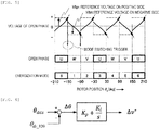
- Fig. 3 shows the relationship between the magnetic saturation induced voltage and the rotor position ⁇ d .
- (1) shown by a solid line is the magnetic saturation induced voltage when a positive pulse is applied from V phase to W phase
- (2) shown by a broken line is the magnetic saturation induced voltage when a negative pulse is applied from W phase to V phase.
- Fig. 4 shows magnetic saturation induced voltages E ou , E ov , and E ow with respect to the rotor position ⁇ d , gate signals G up to G wn , of the switching elements constituting the power converter 3, a rotor position ⁇ d , an energization mode, and a phase relationship of switching, in a case where each phase of U phase, V phase, and W phase are opened.
- Fig. 5 is a waveform of each part in 3 and 6 of the energization mode in Fig. 4 .
- the induced voltage of U phase becomes like a thick arrow on E ou . That is, it is observed that a magnetic saturation induced voltage decreases in the negative direction in the energization mode 3 and increases in the positive direction in the energization mode 6. Every time the energization mode is switched, the induced voltage becomes a waveform that repeats positive and negative rising and decreasing, respectively.
- position sensorless control is realized by setting reference voltages (V hp and V hn ) that are threshold values on the positive side and negative side, respectively, and estimating the rotor position ⁇ d from the magnitude relationship between the reference voltage and the magnetic saturation induced voltage of the open phase.
- V hp and V hn reference voltages
- Ke is an induced voltage coefficient
- R is a winding resistance
- L d is a d-axis inductance
- L q is a q-axis inductance
- I d * is a d-axis current command value
- I q * is a current obtained by applying a first-order delay process having a time constant T to a q-axis current detection value I qc .
- the voltage command compensator 24 which is a feature of the present invention, will be described.
- a voltage correction value ⁇ v* is calculated by the PI controller, based on the phase deviation ⁇ between the phase command value ⁇ dcs and the estimated value ⁇ dc_120 of the rotor position in the 120-degree energization scheme.
- K p is a gain of proportional control
- K i is a gain of integral control.
- a new v qc ** is calculated by replacing the voltage correction value ⁇ v* with ⁇ v q *, and adding ⁇ v q * to the voltage command value v qc * of the q axis as shown in Expression (3).
- v dc ⁇ 0.0
- v qc ⁇ v qc ⁇ + ⁇ v q ⁇ ⁇
- d-q axes which are rotating coordinate systems, dc-qc axes handled by position sensorless control, and an axis error ⁇ which is the phase difference between these axes will be described with reference to Fig. 7 .
- the position of the rotor in the main magnetic flux direction is defined as the d axis, and the direction advanced by 90 degrees from the d axis is defined as the q axis.
- the estimated rotor position is defined as the dc axis, and the direction advanced by 90 degrees from the dc axis is defined as the qc axis.
- the phase difference between the d-q axes and the dc-qc axes is an axis error ⁇ .
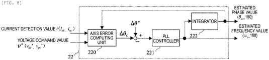
- Fig. 8 shows an internal configuration of the 180-degree position estimator 22.
- An axis error computing unit 220 receives the current detection value I dc , I qc of the dc-qc axes and the voltage command values v dd * and v qc *, and calculates an estimated value ⁇ c of the axis error ⁇ according to Expression (4).
- ⁇ ⁇ c tan ⁇ 1 v dc ⁇ ⁇ RI dc + ⁇ 1 L q ⁇ I qc v qc ⁇ ⁇ RI qc ⁇ ⁇ 1 L q ⁇ I dc
- the PLL controller 221 calculates the estimated speed value ⁇ 1_180 by PI control such that the estimated value ⁇ c of the axis error follows the command value ⁇ * of the axis error which is zero.
- the estimated position value ⁇ dc_180 is calculated.
- ⁇ 1_180 corresponds to ⁇ 1 in Expression (4).
- Figs. 9 and 10 show control characteristics before and after application of the voltage command compensator 24 according to the present invention.
- Fig. 9 is an acceleration characteristic before application of the present invention.
- the speed deviation ⁇ r occurs in the low-speed region, the rotational speed becomes discontinuous during switching to the mid-to-high-speed region, and a current jump-up occurs.
- Fig. 10 is an acceleration characteristic after application of the present invention.
- the rotational speed ⁇ r matches the rotational speed command value ⁇ r * in the low-speed region, and continuity in the low-speed region and the mid-to-high-speed region is maintained, so current jump-up is prevented, and stable and highly accurate speed control characteristics can be realized.
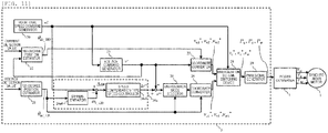
- the voltage correction value ⁇ v* is calculated based on the phase deviation ⁇ between the phase command value ⁇ dcs and the estimated value ⁇ dc_120 of the rotor position in the low-speed region, but in the present example shown in FIG. 11 uses an estimated value of the rotor speed (hereinafter referred to as an estimated speed value), instead of the estimated value of rotor position.
- an estimated speed value an estimated value of the rotor speed
- a voltage command compensator 24a of the present example will be described.
- the estimated value ⁇ dc_120 of the rotor position is input to the differentiator 24a0, the speed deviation ⁇ r between the estimated speed value ⁇ 1_120 of calculated according to Expression (5) and the rotational speed command value ⁇ r * is obtained, and the speed compensation-type speed controller 24a1 calculates integral (I) control to calculate a voltage correction value ⁇ v**.
- ⁇ 1 _ 120 d dt ⁇ dc _ 120
- Fig. 12 shows the configuration of the voltage command compensator 24a.
- the voltage correction value ⁇ v** is calculated by control based on the speed deviation ⁇ r between the rotational speed command value ⁇ r * and the estimated speed value ⁇ 1_120 .
- K i is a gain of integral control.
- v qc *** is calculated by replacing the voltage correction value ⁇ v** with ⁇ v q **, and adding ⁇ v q ** to the voltage command value v qc * of the q axis as shown in Expression (6) .
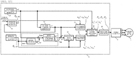
- the rotor position is estimated in the high speed range, but in the present example shown in Fig. 13 , the rotor position and the rotor speed are detected using the Hall IC which is an inexpensive position sensor.
- the magnetic pole position detector 21a of the present embodiment will be described.
- the detected speed value ⁇ r_120' of the rotor speed is calculated according to Expression (7) using the magnetic pole position signal ⁇ n_120' which can be detected every 60 degrees in one electrical angle rotation.
- ⁇ r _ 120 ′ d dt ⁇ n _ 120 ′
- the voltage correction value is added to the q-axis voltage command value, but the correction value may be converted into a three-phase AC voltage command value and added to the three-phase AC voltage command value.
- the same effect can be obtained by using it for correction of the phase command value obtained by integrating the rotational speed command values or the rotational speed command value.
- Fig. 14 is a configuration diagram of a synchronous motor control apparatus according to an example.
- the present example is an application of the present example to a synchronous motor drive system.
- 1 and 2 are the same as those in Fig. 1 .
- the synchronous motor 1 which is a component in Fig. 1 is driven by the power conversion device 4.
- the 2 in Fig. 1 is implemented as software and hardware.
- the level value for switching between the low-speed region and the mid-to-high-speed region may be set from the digital operator 4a of the power conversion device 4, the personal computer 5, the tablet 6, the smartphone 7, or the like.
- It may also be set on a programmable logic controller, a local area network connected to a computer, or a field bus of a control apparatus.
- the switching elements constituting the power converter 2 may be silicon (Si) semiconductor elements, or wide band gap semiconductor devices of silicon carbide (SiC), gallium nitride (GaN), or the like.
- the present invention can be applied to a synchronous motor control apparatus, for example, a synchronous motor control apparatus that estimates a rotor position to control a rotational speed and a torque.
Landscapes
- Engineering & Computer Science (AREA)
- Power Engineering (AREA)
- Control Of Motors That Do Not Use Commutators (AREA)
- Control Of Ac Motors In General (AREA)
Abstract
Description
- The present invention relates to a synchronous motor control apparatus, and to a synchronous motor control apparatus that estimates a rotor position to control a rotational speed and a torque.
- For a control apparatus of a synchronous motor which drives a fan, a pump, a compressor, a conveyor, an elevator, or the like, there are two types of methods of detecting the position of a rotor using a position sensor such as a Hall IC or an encoder, or estimating the position of a rotor by sensorless control without using the position sensor (PTL 1) .
- As the related art, as described in Japanese Patent No.
5972138 -
- PTL 1: Japanese Patent No.
6002643 JP-A-2015-53800 - PTL 2: Japanese Patent No.
5972138 JP-A-2014-79041 - The method of
PTL 1 can realize high torque without step-out even in a stopped state of a synchronous motor, but the current becomes a rectangular wave and torque ripple is generated. Therefore, it is conceivable to switch to the 180-degree energization scheme in the mid-to-high-speed region where an induced voltage can be detected. When switched to a different energization scheme, speed fluctuation, current jump-up, or the like occurs. According to the method ofPTL 2, the voltage to be applied is controlled so that it will change continuously before and after switching of the energization scheme. Since speed control is not performed in the low-speed region driven in the 120-degree energization scheme, when load torque is applied, a deviation occurs between the rotational speed command value and the rotational speed. On the other hand, in the mid-to-high-speed region driven in the 180-degree energization scheme, vector control is applied, so a speed deviation does not occur even when the load torque is applied. That is, since the rotational speed when driven in the 120-degree energization scheme or the 180-degree energization scheme is discontinuous, a speed fluctuation, a current jump-up, and the like occur. - In the present invention, the speed control is performed even in the 120-degree energization scheme, and the speed deviation is made zero such that the rotational speed matches the rotational speed command value. That is, there is provided a control apparatus in which by making the speed deviation zero, continuity of the rotational speed is maintained in the 120-degree energization scheme and the 180-degree energization scheme, and stable and highly accurate speed control characteristics without current jump-up can be realized.
- The present invention relates to a synchronous motor control apparatus which drives a synchronous motor in a 120-degree energization scheme, according to a rotational speed command value, by using a power converter that drives a synchronous motor, the synchronous motor control apparatus including means for detecting a position of a rotor of the synchronous motor directly or by estimation, in which an internal command value of the control apparatus is corrected based on a deviation between a value of the detected position and a phase command value obtained by integrating the rotational speed command value.
- According to the present invention, continuity of the rotational speed is maintained in the 120-degree energization scheme and the 180-degree energization scheme, and stable and highly accurate speed control characteristics without current jump-up can be realized.
-
- [
Fig. 1] Fig. 1 is a configuration diagram of a first embodiment of a control apparatus according to the present invention. - [
Fig. 2] Fig. 2 is an explanatory diagram in a case where a voltage is applied to a two-phase winding of a synchronous motor. - [
Fig. 3] Fig. 3 is a characteristic diagram of magnetic saturation induced voltage. - [
Fig. 4] Fig. 4 is a characteristic diagram of the magnetic saturation induced voltage with respect to the rotor position. - [
Fig. 5] Fig. 5 is an explanatory diagram of a relationship between the magnetic saturation induced voltage and a reference voltage with respect to a rotor position. - [
Fig. 6] Fig. 6 is a configuration diagram of a phase compensation-type speed controller. - [
Fig. 7] Fig. 7 is an explanatory diagram of a d-q axis rotational coordinate system. - [
Fig. 8] Fig. 8 is a configuration diagram of a 180-degree position estimator. - [
Fig. 9] Fig. 9 is an acceleration characteristic diagram before application of the present invention. - [
Fig. 10] Fig. 10 is an acceleration characteristic diagram after application of the present invention. - [
Fig. 11] Fig. 11 is a configuration diagram of a second embodiment of the control apparatus according to the present invention. - [
Fig. 12] Fig. 12 is a configuration diagram of a speed compensation-type speed controller. - [
Fig. 13] Fig. 13 is a configuration diagram of the second embodiment of the control apparatus according to the present invention. - [
Fig. 14] Fig. 14 is a configuration diagram of a synchronous motor control apparatus according to an example. - The configuration and operation of a synchronous motor control apparatus will be described below with reference to
Figs. 1 to 14 regarding the configuration of the present invention. Further, the present invention is not limited to the following embodiments, and various modification examples and application examples of the technical concept of the present invention are included within the scope thereof. Hereinafter, examples will be described with reference to the drawings. -
Fig. 1 shows a first embodiment of the present invention. - In this example, a rotor position in a low-speed region is detected by position sensorless control of a 120-degree energization scheme.
- A
synchronous motor 1 is a permanent magnet synchronous motor having a permanent magnet in a rotor, and generates a torque by a magnet magnetic flux and a current of a torque current component (q axis) orthogonal to a magnetic flux component (d axis). - The
controller 2 calculates three-phase voltage command values vu*, vv*, and vw* from the voltage command values vdc* and vqc* of the d axis and the q axis, which are voltage command value v*, and outputs signals Pu, Pv, and Pw obtained by converting them into pulse widths. - The power converter 3 outputs voltage values in proportion to the pulse width signals Pu, Pv, and Pw, and varies the output voltage and the output frequency of the
synchronous motor 1. - Next, the configuration of the
controller 2 will be described. - The rotational
speed command generator 20 outputs the rotational speed command value ωr* of thesynchronous motor 1. - The 120-
degree position estimator 21 outputs the estimated value θdc_120 of the rotor position in the low-speed region by using the voltage detection values Eou, Eov, and Eow. - The 180-
degree position estimator 22 outputs the estimated value θdc_180 of the rotor position in the mid-to-high-speed region by using the voltage commands vdc* and vqc* of the d axis and the q axis and the current detection values Idc and Iqc. - The
voltage command generator 23 outputs the voltage command values vdc* and vqc* of the d axis and the q axis which are voltage command values v* by using the electric constant of thesynchronous motor 1 and the rotational speed command value ωr*. - The
voltage command compensator 24, which is a feature of the present invention, receives the rotational speed command value ωr* and the estimated value θdc_120 of the rotor position, and outputs the voltage correction value Δv*. - The internal configuration of
voltage command compensator 24 will be described. The phase deviation Δθ between the phase command value θdcs obtained by integrating ωr* by theintegrator 240 and the estimated value θdc_120 of the rotor position is calculated, and the phase compensation-type speed controller 241 calculates proportional integral (PI) control to calculate the voltage correction value Δv. - The
energization mode selector 25 determines any two energization phases of the u, v, and w phases of thesynchronous motor 1 when driving in the 120-degree energization scheme. - The
coordinate converter 26 converts the voltage command values vdc* and vqc** of the d axis and the q axis in the 120-degree energization scheme into the three-phase voltage command values vu1*, vv1*, and vw1*, and outputs the converted values. - The
coordinate converter 27 converts the voltage command values vdc* and vqc* of the d axis and the q axis in the 180-degree energization scheme into the three-phase voltage command values vu2*, vv2*, and vw2*, and outputs the converted values. - If the magnitude of rotor speed command ωr* is 10% or less of the rated speed of
synchronous motor 1, the energizationscheme switching device 28 determines that the motor is in the low speed region and selects the voltage command values vu1*, vv1*, and vw1*, and if the magnitude of ωr* is 10% or more of the rated speed, and outputs the selected values as vu*, vv*, and vw*, it determines that the motor is in the mid-to-high-speed region and selects vu2*, vv2*, and vw2*. - The
PWM signal generator 29 outputs the pulse width signals Pu, Pv, and Pw corresponding to the input three-phase voltage command values vu*, vv*, and vw*. - The basic operation in the present example will now be described.
- First, in the low speed range, a method of estimating the rotor position based on the magnetic saturation induced voltage of
PTL 2 used in the 120-degree position estimator 21 will be described. - In the 120-degree energization scheme, a voltage is applied to two phases of the three-phase winding of the
synchronous motor 1.Figs. 2(a) and 2(b) are explanatory diagrams in the case where current is passed from V phase to W phase, and from W phase to V phase, respectively. At this time, a voltage corresponding to the rotor position is generated in U phase which is an open phase to which a voltage is not applied. This voltage is a magnetic saturation induced voltage generated when the inductance in the motor slightly changes due to the relationship between the magnetic flux from the permanent magnet of thesynchronous motor 1 and the energization current. -
Fig. 3 shows the relationship between the magnetic saturation induced voltage and the rotor position θd. InFig. 3 , (1) shown by a solid line is the magnetic saturation induced voltage when a positive pulse is applied from V phase to W phase, and (2) shown by a broken line is the magnetic saturation induced voltage when a negative pulse is applied from W phase to V phase. -
Fig. 4 shows magnetic saturation induced voltages Eou, Eov, and Eow with respect to the rotor position θd, gate signals Gup to Gwn, of the switching elements constituting thepower converter 3, a rotor position θd, an energization mode, and a phase relationship of switching, in a case where each phase of U phase, V phase, and W phase are opened. -
Fig. 5 is a waveform of each part in 3 and 6 of the energization mode inFig. 4 . The induced voltage of U phase becomes like a thick arrow on Eou. That is, it is observed that a magnetic saturation induced voltage decreases in the negative direction in theenergization mode 3 and increases in the positive direction in theenergization mode 6. Every time the energization mode is switched, the induced voltage becomes a waveform that repeats positive and negative rising and decreasing, respectively. Therefore, position sensorless control is realized by setting reference voltages (Vhp and Vhn) that are threshold values on the positive side and negative side, respectively, and estimating the rotor position θd from the magnitude relationship between the reference voltage and the magnetic saturation induced voltage of the open phase. Here, the voltage command values v* in the low-speed region and the mid-to-high-speed region calculated by thevoltage command generator 23 will be described. - In the case of driving in the 120-degree energization scheme in the low-speed region, the d-axis voltage command value vdc* is zero, and only the q-axis voltage command value vqc* is calculated, as shown in Expression (1) .
[Expression 1]
- Here, Ke is an induced voltage coefficient.
- In the case of driving in the 180-degree energization scheme in the mid-to-high-speed region, the voltage command values vdc* of the d axis and the q axis are calculated, as shown in Expression (2).
[Expression 2]
- Here, R is a winding resistance, Ld is a d-axis inductance, Lq is a q-axis inductance, Id* is a d-axis current command value, and Iq* is a current obtained by applying a first-order delay process having a time constant T to a q-axis current detection value Iqc.
- The
voltage command compensator 24, which is a feature of the present invention, will be described. - The configuration of the
voltage command compensator 24 is shown inFig. 6 . A voltage correction value Δv* is calculated by the PI controller, based on the phase deviation Δθ between the phase command value θdcs and the estimated value θdc_120 of the rotor position in the 120-degree energization scheme. Here, Kp is a gain of proportional control, and Ki is a gain of integral control. - A new vqc** is calculated by replacing the voltage correction value Δv* with Δvq*, and adding Δvq* to the voltage command value vqc* of the q axis as shown in Expression (3).
[Expression 3]
- Next, position sensorless control in the mid-to-high-speed region will be described.
- d-q axes which are rotating coordinate systems, dc-qc axes handled by position sensorless control, and an axis error Δθ which is the phase difference between these axes will be described with reference to
Fig. 7 . The position of the rotor in the main magnetic flux direction is defined as the d axis, and the direction advanced by 90 degrees from the d axis is defined as the q axis. On the other hand, on the control axis, the estimated rotor position is defined as the dc axis, and the direction advanced by 90 degrees from the dc axis is defined as the qc axis. The phase difference between the d-q axes and the dc-qc axes is an axis error Δθ. -
Fig. 8 shows an internal configuration of the 180-degree position estimator 22. An axiserror computing unit 220 receives the current detection value Idc, Iqc of the dc-qc axes and the voltage command values vdd* and vqc*, and calculates an estimated value Δθc of the axis error Δθ according to Expression (4).
[Expression 4]
- The
PLL controller 221 calculates the estimated speed value ω1_180 by PI control such that the estimated value Δθc of the axis error follows the command value Δθ* of the axis error which is zero. By integrating the estimated speed value ω1_180 by theintegrator 222, the estimated position value θdc_180 is calculated. Here, ω1_180 corresponds to ω1 in Expression (4). -
Figs. 9 and10 show control characteristics before and after application of thevoltage command compensator 24 according to the present invention.Fig. 9 is an acceleration characteristic before application of the present invention. The speed deviation Δωr occurs in the low-speed region, the rotational speed becomes discontinuous during switching to the mid-to-high-speed region, and a current jump-up occurs. -
Fig. 10 is an acceleration characteristic after application of the present invention. The rotational speed ωr matches the rotational speed command value ωr* in the low-speed region, and continuity in the low-speed region and the mid-to-high-speed region is maintained, so current jump-up is prevented, and stable and highly accurate speed control characteristics can be realized. - In the first example, the voltage correction value Δv* is calculated based on the phase deviation Δθ between the phase command value θdcs and the estimated value θdc_120 of the rotor position in the low-speed region, but in the present example shown in
FIG. 11 uses an estimated value of the rotor speed (hereinafter referred to as an estimated speed value), instead of the estimated value of rotor position. - 1, 20 to 23, 25 to 29, and 3 in
Fig. 11 are the same as those inFig. 1 . - A
voltage command compensator 24a of the present example will be described. - The estimated value θdc_120 of the rotor position is input to the differentiator 24a0, the speed deviation Δωr between the estimated speed value θ1_120 of calculated according to Expression (5) and the rotational speed command value ωr* is obtained, and the speed compensation-type speed controller 24a1 calculates integral (I) control to calculate a voltage correction value Δv**.
[Expression 5]
-
Fig. 12 shows the configuration of thevoltage command compensator 24a. - The voltage correction value Δv** is calculated by control based on the speed deviation Δωr between the rotational speed command value ωr* and the estimated speed value ω1_120. Here, Ki is a gain of integral control.
- A new vqc*** is calculated by replacing the voltage correction value Δv** with Δvq**, and adding Δvq** to the voltage command value vqc* of the q axis as shown in Expression (6) .
[Expression 6]
- Even with the control configuration as in the present example, continuity in the low-speed region and the mid-to-high-speed region is maintained, so current jump-up is prevented, and stable and highly accurate speed control characteristics can be realized.
- In the first example, the rotor position is estimated in the high speed range, but in the present example shown in
Fig. 13 , the rotor position and the rotor speed are detected using the Hall IC which is an inexpensive position sensor. - 1, 20, 22 to 29, and 3 in the drawing are the same as those in
Fig. 1 . - The magnetic pole position detector 21a of the present embodiment will be described. In the detection of the rotor speed, the detected speed value ωr_120' of the rotor speed is calculated according to Expression (7) using the magnetic pole position signal θn_120' which can be detected every 60 degrees in one electrical angle rotation.
[Expression 7]
- With respect to the low-speed region, as in the second example, the voltage correction value is calculated based on the speed deviation (= ωr* - ωr_120') between the rotational speed command value ωr* and the detected speed value ωr_120', so even in a case of using an inexpensive rotor position sensor, continuity in the low-speed region and the mid-to-high-speed region is maintained, so current jump-up is prevented, and stable and highly accurate speed control characteristics can be realized.
- In the first to third examples, the voltage correction value is added to the q-axis voltage command value, but the correction value may be converted into a three-phase AC voltage command value and added to the three-phase AC voltage command value. Alternatively, the same effect can be obtained by using it for correction of the phase command value obtained by integrating the rotational speed command values or the rotational speed command value.
-
Fig. 14 is a configuration diagram of a synchronous motor control apparatus according to an example. The present example is an application of the present example to a synchronous motor drive system. InFig. 14 ,1 and2 are the same as those inFig. 1 . - The
synchronous motor 1 which is a component inFig. 1 is driven by thepower conversion device 4. In thepower converter 4, the 2 inFig. 1 is implemented as software and hardware. - The level value for switching between the low-speed region and the mid-to-high-speed region may be set from the
digital operator 4a of thepower conversion device 4, thepersonal computer 5, thetablet 6, thesmartphone 7, or the like. - It may also be set on a programmable logic controller, a local area network connected to a computer, or a field bus of a control apparatus.
- If the present example is applied to a synchronous motor drive system, it is possible to prevent the current jump-up and to realize stable and highly accurate speed control characteristics.
- Further, although the present embodiment is disclosed using the first example, it may be disclosed by the second and third examples . In the first to fourth examples, the switching elements constituting the
power converter 2 may be silicon (Si) semiconductor elements, or wide band gap semiconductor devices of silicon carbide (SiC), gallium nitride (GaN), or the like. - The present invention can be applied to a synchronous motor control apparatus, for example, a synchronous motor control apparatus that estimates a rotor position to control a rotational speed and a torque.
-
- 1: synchronous motor
- 2: controller
- 20: rotational speed command generator
- 21: 120-degree position estimator
- 21a: magnetic pole position detector
- 22: 180-degree position estimator
- 23: voltage command generator
- 24, 24a: voltage command compensator
- 240: integrator
- 24a0: differentiator
- 241: phase compensation-type speed controller
- 24a1: speed compensation-type speed controller
- 25: energization mode determiner
- 26, 27: coordinate converter
- 28: energization scheme switching device
- 29: PWM signal generator
- 3: power converter
- 4: power conversion device
- 4a: digital operator
- 5: personal computer
- 6: tablet
- 7: smartphone
- ωr*: rotational speed command value
- ωr: rotational speed
- Δωr: speed deviation
- θdc_120, θdc_180: estimated value of rotor position
- θn_120': magnetic pole position signal
- ω1_120, ω1_180: estimated speed value
- ωr_120': detected speed value
- vdc*: current command value of d axis
- vqc*, vqc*: current command value of q axis
- Δv*, Δv**, Δvq*, Δvq**: voltage correction value
- vu1*, vv1*, vw1*, vu2*, vv2*, vw2*, vu*, vv*, vw*: three-phase voltage command value
- Pu, Pv, Pw: pulse width signal
- Eou, Eov, Eow: magnetic saturation induced voltage
Claims (8)
- A synchronous motor control apparatus which drives a synchronous motor in a 120-degree energization scheme, according to a rotational speed command value, using a power converter that drives the synchronous motor, the synchronous motor control apparatus comprising:any one of means for detecting a position of a rotor of the synchronous motor directly or by estimation, whereinan internal command value of the control apparatus is corrected based on a deviation between a value of the detected position and a phase command value obtained by integrating the rotational speed command value.
- A synchronous motor control apparatus which drives a synchronous motor in a 120-degree energization scheme, according to a rotational speed command value, using a power converter that drives the synchronous motor, the synchronous motor control apparatus comprising:any one of means for detecting a position of a rotor of the synchronous motor directly or by estimation, whereinan internal command value of the control apparatus is corrected based on a deviation between a detected speed value obtained by differentiating a value of the detected position and the rotational speed command value.
- The synchronous motor control apparatus according to claim 1 or 2, wherein
the internal command value of the control apparatus is a voltage command value related to a torque component, an amplitude value of a three-phase voltage command value, a phase command value obtained by integrating a rotational speed command value, or a rotational speed command value. - The synchronous motor control apparatus according to any one of claims 1 to 3, wherein
a low-speed region is driven at a 120-degree energization scheme, and a mid-to-high-speed region is driven at a 180-degree energization scheme, according to the rotational speed command value or the detected speed value of the synchronous motor. - The synchronous motor control apparatus according to claim 4, wherein
in the low-speed region, a rotational speed is 10% or less of a rated rotational speed of the synchronous motor, and in the mid-to-high speed region, the rotational speed is 10% or more of the rated rotational speed. - The synchronous motor control apparatus according to claim 4, wherein
a level value for switching the energization scheme of the synchronous motor is set from the outside of the control apparatus. - The synchronous motor control apparatus according to claim 6, wherein
the outside of the control apparatus is a personal computer, a tablet, or a smart phone which is an external device, and the level value for switching the energization scheme of the synchronous motor is capable of being freely set and changed through the personal computer, the tablet, or the smart phone. - The synchronous motor control apparatus according to claim 6, wherein
the outside of the control apparatus is a programmable logic controller which is a host device, a local area network connected to a computer, or a field bus of a control apparatus, and the level value for switching the energization scheme of the synchronous motor is capable of being freely set and changed through the programmable logic controller, the local area network, or the field bus of the control apparatus.
Applications Claiming Priority (2)
| Application Number | Priority Date | Filing Date | Title |
|---|---|---|---|
| JP2017060354A JP6707050B2 (en) | 2017-03-27 | 2017-03-27 | Synchronous motor controller |
| PCT/JP2018/008045 WO2018180203A1 (en) | 2017-03-27 | 2018-03-02 | Synchronous motor control apparatus |
Publications (3)
| Publication Number | Publication Date |
|---|---|
| EP3605830A1 true EP3605830A1 (en) | 2020-02-05 |
| EP3605830A4 EP3605830A4 (en) | 2020-11-18 |
| EP3605830B1 EP3605830B1 (en) | 2024-05-01 |
Family
ID=63677075
Family Applications (1)
| Application Number | Title | Priority Date | Filing Date |
|---|---|---|---|
| EP18775186.2A Active EP3605830B1 (en) | 2017-03-27 | 2018-03-02 | Synchronous motor control apparatus |
Country Status (5)
| Country | Link |
|---|---|
| US (1) | US10903767B2 (en) |
| EP (1) | EP3605830B1 (en) |
| JP (1) | JP6707050B2 (en) |
| CN (1) | CN110140290B (en) |
| WO (1) | WO2018180203A1 (en) |
Families Citing this family (3)
| Publication number | Priority date | Publication date | Assignee | Title |
|---|---|---|---|---|
| US12155325B2 (en) * | 2020-04-03 | 2024-11-26 | Rohm Co., Ltd. | Motor control unit and motor device |
| CN116057826A (en) * | 2020-09-03 | 2023-05-02 | 日立安斯泰莫株式会社 | Control device and control method for brushless motor |
| JP7808201B2 (en) * | 2022-09-22 | 2026-01-28 | Astemo株式会社 | Motor control device and motor control method |
Family Cites Families (15)
| Publication number | Priority date | Publication date | Assignee | Title |
|---|---|---|---|---|
| JPS602643B2 (en) | 1976-11-30 | 1985-01-23 | 日本セルフオツク株式会社 | Optical coupling branch circuit using focusing optical transmitter |
| JPH07118944B2 (en) * | 1986-03-17 | 1995-12-18 | 株式会社日立製作所 | Brushless DC motor |
| JP3399156B2 (en) * | 1995-05-29 | 2003-04-21 | 株式会社デンソー | Control device for brushless DC motor |
| JP3892823B2 (en) * | 2003-03-17 | 2007-03-14 | 山洋電気株式会社 | Motor speed control device |
| US7265511B2 (en) | 2003-03-17 | 2007-09-04 | Sanyo Denki Co., Ltd. | Motor control device |
| JP4193120B2 (en) * | 2003-05-19 | 2008-12-10 | 株式会社デンソー | Motor control device |
| JP4294602B2 (en) * | 2005-02-18 | 2009-07-15 | パナソニック株式会社 | Rotor magnetic pole position detecting device for multiphase motor, motor driving device including the same, and motor driving method |
| JP2009142064A (en) * | 2007-12-06 | 2009-06-25 | Nippon Densan Corp | Brushless motor |
| DE112009000209T5 (en) * | 2008-03-04 | 2011-01-05 | Mitsubishi Electric Corp. | Brushless device and control device |
| CN101262196B (en) * | 2008-04-29 | 2010-06-02 | 重庆大学 | Method for detecting rotor position of brushless DC motor without position sensor |
| JP5509167B2 (en) * | 2011-09-08 | 2014-06-04 | 株式会社日立産機システム | Synchronous motor control system |
| KR101953124B1 (en) * | 2012-07-13 | 2019-03-04 | 삼성전자주식회사 | Driving apparatus of motor and cooling apparatus using the same |
| JP5972138B2 (en) * | 2012-10-09 | 2016-08-17 | 日立アプライアンス株式会社 | Electric motor control device, refrigerator using the same, and electric device |
| JP6002643B2 (en) | 2013-09-06 | 2016-10-05 | 株式会社日立産機システム | Control device and AC motor system using the same |
| CN105763119B (en) * | 2016-04-20 | 2018-06-01 | 北京控制工程研究所 | A kind of control system and control method of CMG frames permanent magnet synchronous motor |
-
2017
- 2017-03-27 JP JP2017060354A patent/JP6707050B2/en active Active
-
2018
- 2018-03-02 US US16/483,813 patent/US10903767B2/en active Active
- 2018-03-02 WO PCT/JP2018/008045 patent/WO2018180203A1/en not_active Ceased
- 2018-03-02 CN CN201880005425.8A patent/CN110140290B/en active Active
- 2018-03-02 EP EP18775186.2A patent/EP3605830B1/en active Active
Also Published As
| Publication number | Publication date |
|---|---|
| JP6707050B2 (en) | 2020-06-10 |
| US10903767B2 (en) | 2021-01-26 |
| JP2018164360A (en) | 2018-10-18 |
| US20200052620A1 (en) | 2020-02-13 |
| EP3605830B1 (en) | 2024-05-01 |
| EP3605830A4 (en) | 2020-11-18 |
| CN110140290B (en) | 2022-12-20 |
| WO2018180203A1 (en) | 2018-10-04 |
| CN110140290A (en) | 2019-08-16 |
Similar Documents
| Publication | Publication Date | Title |
|---|---|---|
| JP5155344B2 (en) | Electric motor magnetic pole position estimation device | |
| KR101046802B1 (en) | Control device of AC rotor and electric constant measurement method of AC rotor using this controller | |
| EP3252941B1 (en) | Inverter control apparatus and motor driving system | |
| EP3252942A1 (en) | Inverter control device and motor drive system | |
| JP2009142116A (en) | Position sensorless control device for permanent magnet motor | |
| EP3267577B1 (en) | Power conversion device and method for controlling same | |
| EP3817218B1 (en) | Power conversion apparatus | |
| US10637381B2 (en) | Inverter control device and drive system | |
| JP6908888B2 (en) | Synchronous motor control device | |
| WO2008004417A1 (en) | Sensorless control apparatus of synchronous machine | |
| EP2755319B1 (en) | Control system for synchronous motor | |
| US10903767B2 (en) | Synchronous motor control apparatus | |
| EP3614559A1 (en) | Induction motor speed estimation method and power conversion device using same | |
| EP3910782A1 (en) | Power conversion device | |
| EP3128668A1 (en) | Electric apparatus drive device | |
| US7279865B2 (en) | Method and apparatus for monitoring motor status using induced motor voltage | |
| JP5186352B2 (en) | Electric motor magnetic pole position estimation device | |
| JP6573213B2 (en) | Control device for permanent magnet type synchronous motor | |
| CN111034022A (en) | Power conversion device and control method thereof | |
| JP6108109B2 (en) | Control device for permanent magnet type synchronous motor | |
| EP3214753B1 (en) | Power conversion device and method for controlling power conversion device | |
| JP6787006B2 (en) | Motor control device |
Legal Events
| Date | Code | Title | Description |
|---|---|---|---|
| STAA | Information on the status of an ep patent application or granted ep patent |
Free format text: STATUS: THE INTERNATIONAL PUBLICATION HAS BEEN MADE |
|
| PUAI | Public reference made under article 153(3) epc to a published international application that has entered the european phase |
Free format text: ORIGINAL CODE: 0009012 |
|
| STAA | Information on the status of an ep patent application or granted ep patent |
Free format text: STATUS: REQUEST FOR EXAMINATION WAS MADE |
|
| 17P | Request for examination filed |
Effective date: 20190705 |
|
| AK | Designated contracting states |
Kind code of ref document: A1 Designated state(s): AL AT BE BG CH CY CZ DE DK EE ES FI FR GB GR HR HU IE IS IT LI LT LU LV MC MK MT NL NO PL PT RO RS SE SI SK SM TR |
|
| AX | Request for extension of the european patent |
Extension state: BA ME |
|
| DAV | Request for validation of the european patent (deleted) | ||
| DAX | Request for extension of the european patent (deleted) | ||
| A4 | Supplementary search report drawn up and despatched |
Effective date: 20201021 |
|
| RIC1 | Information provided on ipc code assigned before grant |
Ipc: H02P 6/182 20160101AFI20201015BHEP |
|
| STAA | Information on the status of an ep patent application or granted ep patent |
Free format text: STATUS: EXAMINATION IS IN PROGRESS |
|
| 17Q | First examination report despatched |
Effective date: 20210407 |
|
| RIC1 | Information provided on ipc code assigned before grant |
Ipc: H02P 21/00 20160101ALI20220929BHEP Ipc: H02P 21/34 20160101ALI20220929BHEP Ipc: H02P 21/26 20160101ALI20220929BHEP Ipc: H02P 6/18 20160101ALI20220929BHEP Ipc: H02P 6/182 20160101AFI20220929BHEP |
|
| GRAJ | Information related to disapproval of communication of intention to grant by the applicant or resumption of examination proceedings by the epo deleted |
Free format text: ORIGINAL CODE: EPIDOSDIGR1 |
|
| STAA | Information on the status of an ep patent application or granted ep patent |
Free format text: STATUS: GRANT OF PATENT IS INTENDED |
|
| GRAP | Despatch of communication of intention to grant a patent |
Free format text: ORIGINAL CODE: EPIDOSNIGR1 |
|
| INTG | Intention to grant announced |
Effective date: 20240123 |
|
| GRAS | Grant fee paid |
Free format text: ORIGINAL CODE: EPIDOSNIGR3 |
|
| GRAA | (expected) grant |
Free format text: ORIGINAL CODE: 0009210 |
|
| STAA | Information on the status of an ep patent application or granted ep patent |
Free format text: STATUS: THE PATENT HAS BEEN GRANTED |
|
| AK | Designated contracting states |
Kind code of ref document: B1 Designated state(s): AL AT BE BG CH CY CZ DE DK EE ES FI FR GB GR HR HU IE IS IT LI LT LU LV MC MK MT NL NO PL PT RO RS SE SI SK SM TR |
|
| REG | Reference to a national code |
Ref country code: GB Ref legal event code: FG4D |
|
| REG | Reference to a national code |
Ref country code: CH Ref legal event code: EP |
|
| REG | Reference to a national code |
Ref country code: DE Ref legal event code: R096 Ref document number: 602018068962 Country of ref document: DE |
|
| REG | Reference to a national code |
Ref country code: IE Ref legal event code: FG4D |
|
| REG | Reference to a national code |
Ref country code: LT Ref legal event code: MG9D |
|
| REG | Reference to a national code |
Ref country code: NL Ref legal event code: MP Effective date: 20240501 |
|
| PG25 | Lapsed in a contracting state [announced via postgrant information from national office to epo] |
Ref country code: IS Free format text: LAPSE BECAUSE OF FAILURE TO SUBMIT A TRANSLATION OF THE DESCRIPTION OR TO PAY THE FEE WITHIN THE PRESCRIBED TIME-LIMIT Effective date: 20240901 |
|
| PG25 | Lapsed in a contracting state [announced via postgrant information from national office to epo] |
Ref country code: BG Free format text: LAPSE BECAUSE OF FAILURE TO SUBMIT A TRANSLATION OF THE DESCRIPTION OR TO PAY THE FEE WITHIN THE PRESCRIBED TIME-LIMIT Effective date: 20240501 |
|
| PG25 | Lapsed in a contracting state [announced via postgrant information from national office to epo] |
Ref country code: FI Free format text: LAPSE BECAUSE OF FAILURE TO SUBMIT A TRANSLATION OF THE DESCRIPTION OR TO PAY THE FEE WITHIN THE PRESCRIBED TIME-LIMIT Effective date: 20240501 Ref country code: HR Free format text: LAPSE BECAUSE OF FAILURE TO SUBMIT A TRANSLATION OF THE DESCRIPTION OR TO PAY THE FEE WITHIN THE PRESCRIBED TIME-LIMIT Effective date: 20240501 |
|
| PG25 | Lapsed in a contracting state [announced via postgrant information from national office to epo] |
Ref country code: GR Free format text: LAPSE BECAUSE OF FAILURE TO SUBMIT A TRANSLATION OF THE DESCRIPTION OR TO PAY THE FEE WITHIN THE PRESCRIBED TIME-LIMIT Effective date: 20240802 |
|
| PG25 | Lapsed in a contracting state [announced via postgrant information from national office to epo] |
Ref country code: PT Free format text: LAPSE BECAUSE OF FAILURE TO SUBMIT A TRANSLATION OF THE DESCRIPTION OR TO PAY THE FEE WITHIN THE PRESCRIBED TIME-LIMIT Effective date: 20240902 |
|
| REG | Reference to a national code |
Ref country code: AT Ref legal event code: MK05 Ref document number: 1683781 Country of ref document: AT Kind code of ref document: T Effective date: 20240501 |
|
| PG25 | Lapsed in a contracting state [announced via postgrant information from national office to epo] |
Ref country code: NL Free format text: LAPSE BECAUSE OF FAILURE TO SUBMIT A TRANSLATION OF THE DESCRIPTION OR TO PAY THE FEE WITHIN THE PRESCRIBED TIME-LIMIT Effective date: 20240501 |
|
| PG25 | Lapsed in a contracting state [announced via postgrant information from national office to epo] |
Ref country code: ES Free format text: LAPSE BECAUSE OF FAILURE TO SUBMIT A TRANSLATION OF THE DESCRIPTION OR TO PAY THE FEE WITHIN THE PRESCRIBED TIME-LIMIT Effective date: 20240501 |
|
| PG25 | Lapsed in a contracting state [announced via postgrant information from national office to epo] |
Ref country code: AT Free format text: LAPSE BECAUSE OF FAILURE TO SUBMIT A TRANSLATION OF THE DESCRIPTION OR TO PAY THE FEE WITHIN THE PRESCRIBED TIME-LIMIT Effective date: 20240501 |
|
| PG25 | Lapsed in a contracting state [announced via postgrant information from national office to epo] |
Ref country code: PL Free format text: LAPSE BECAUSE OF FAILURE TO SUBMIT A TRANSLATION OF THE DESCRIPTION OR TO PAY THE FEE WITHIN THE PRESCRIBED TIME-LIMIT Effective date: 20240501 |
|
| PG25 | Lapsed in a contracting state [announced via postgrant information from national office to epo] |
Ref country code: LV Free format text: LAPSE BECAUSE OF FAILURE TO SUBMIT A TRANSLATION OF THE DESCRIPTION OR TO PAY THE FEE WITHIN THE PRESCRIBED TIME-LIMIT Effective date: 20240501 |
|
| PG25 | Lapsed in a contracting state [announced via postgrant information from national office to epo] |
Ref country code: PT Free format text: LAPSE BECAUSE OF FAILURE TO SUBMIT A TRANSLATION OF THE DESCRIPTION OR TO PAY THE FEE WITHIN THE PRESCRIBED TIME-LIMIT Effective date: 20240902 Ref country code: PL Free format text: LAPSE BECAUSE OF FAILURE TO SUBMIT A TRANSLATION OF THE DESCRIPTION OR TO PAY THE FEE WITHIN THE PRESCRIBED TIME-LIMIT Effective date: 20240501 Ref country code: NO Free format text: LAPSE BECAUSE OF FAILURE TO SUBMIT A TRANSLATION OF THE DESCRIPTION OR TO PAY THE FEE WITHIN THE PRESCRIBED TIME-LIMIT Effective date: 20240801 Ref country code: NL Free format text: LAPSE BECAUSE OF FAILURE TO SUBMIT A TRANSLATION OF THE DESCRIPTION OR TO PAY THE FEE WITHIN THE PRESCRIBED TIME-LIMIT Effective date: 20240501 Ref country code: LV Free format text: LAPSE BECAUSE OF FAILURE TO SUBMIT A TRANSLATION OF THE DESCRIPTION OR TO PAY THE FEE WITHIN THE PRESCRIBED TIME-LIMIT Effective date: 20240501 Ref country code: IS Free format text: LAPSE BECAUSE OF FAILURE TO SUBMIT A TRANSLATION OF THE DESCRIPTION OR TO PAY THE FEE WITHIN THE PRESCRIBED TIME-LIMIT Effective date: 20240901 Ref country code: HR Free format text: LAPSE BECAUSE OF FAILURE TO SUBMIT A TRANSLATION OF THE DESCRIPTION OR TO PAY THE FEE WITHIN THE PRESCRIBED TIME-LIMIT Effective date: 20240501 Ref country code: GR Free format text: LAPSE BECAUSE OF FAILURE TO SUBMIT A TRANSLATION OF THE DESCRIPTION OR TO PAY THE FEE WITHIN THE PRESCRIBED TIME-LIMIT Effective date: 20240802 Ref country code: FI Free format text: LAPSE BECAUSE OF FAILURE TO SUBMIT A TRANSLATION OF THE DESCRIPTION OR TO PAY THE FEE WITHIN THE PRESCRIBED TIME-LIMIT Effective date: 20240501 Ref country code: ES Free format text: LAPSE BECAUSE OF FAILURE TO SUBMIT A TRANSLATION OF THE DESCRIPTION OR TO PAY THE FEE WITHIN THE PRESCRIBED TIME-LIMIT Effective date: 20240501 Ref country code: BG Free format text: LAPSE BECAUSE OF FAILURE TO SUBMIT A TRANSLATION OF THE DESCRIPTION OR TO PAY THE FEE WITHIN THE PRESCRIBED TIME-LIMIT Effective date: 20240501 Ref country code: AT Free format text: LAPSE BECAUSE OF FAILURE TO SUBMIT A TRANSLATION OF THE DESCRIPTION OR TO PAY THE FEE WITHIN THE PRESCRIBED TIME-LIMIT Effective date: 20240501 Ref country code: RS Free format text: LAPSE BECAUSE OF FAILURE TO SUBMIT A TRANSLATION OF THE DESCRIPTION OR TO PAY THE FEE WITHIN THE PRESCRIBED TIME-LIMIT Effective date: 20240801 |
|
| PG25 | Lapsed in a contracting state [announced via postgrant information from national office to epo] |
Ref country code: DK Free format text: LAPSE BECAUSE OF FAILURE TO SUBMIT A TRANSLATION OF THE DESCRIPTION OR TO PAY THE FEE WITHIN THE PRESCRIBED TIME-LIMIT Effective date: 20240501 |
|
| PG25 | Lapsed in a contracting state [announced via postgrant information from national office to epo] |
Ref country code: EE Free format text: LAPSE BECAUSE OF FAILURE TO SUBMIT A TRANSLATION OF THE DESCRIPTION OR TO PAY THE FEE WITHIN THE PRESCRIBED TIME-LIMIT Effective date: 20240501 |
|
| PG25 | Lapsed in a contracting state [announced via postgrant information from national office to epo] |
Ref country code: CZ Free format text: LAPSE BECAUSE OF FAILURE TO SUBMIT A TRANSLATION OF THE DESCRIPTION OR TO PAY THE FEE WITHIN THE PRESCRIBED TIME-LIMIT Effective date: 20240501 |
|
| PG25 | Lapsed in a contracting state [announced via postgrant information from national office to epo] |
Ref country code: SK Free format text: LAPSE BECAUSE OF FAILURE TO SUBMIT A TRANSLATION OF THE DESCRIPTION OR TO PAY THE FEE WITHIN THE PRESCRIBED TIME-LIMIT Effective date: 20240501 Ref country code: RO Free format text: LAPSE BECAUSE OF FAILURE TO SUBMIT A TRANSLATION OF THE DESCRIPTION OR TO PAY THE FEE WITHIN THE PRESCRIBED TIME-LIMIT Effective date: 20240501 |
|
| PG25 | Lapsed in a contracting state [announced via postgrant information from national office to epo] |
Ref country code: SM Free format text: LAPSE BECAUSE OF FAILURE TO SUBMIT A TRANSLATION OF THE DESCRIPTION OR TO PAY THE FEE WITHIN THE PRESCRIBED TIME-LIMIT Effective date: 20240501 |
|
| PG25 | Lapsed in a contracting state [announced via postgrant information from national office to epo] |
Ref country code: SM Free format text: LAPSE BECAUSE OF FAILURE TO SUBMIT A TRANSLATION OF THE DESCRIPTION OR TO PAY THE FEE WITHIN THE PRESCRIBED TIME-LIMIT Effective date: 20240501 Ref country code: SK Free format text: LAPSE BECAUSE OF FAILURE TO SUBMIT A TRANSLATION OF THE DESCRIPTION OR TO PAY THE FEE WITHIN THE PRESCRIBED TIME-LIMIT Effective date: 20240501 Ref country code: RO Free format text: LAPSE BECAUSE OF FAILURE TO SUBMIT A TRANSLATION OF THE DESCRIPTION OR TO PAY THE FEE WITHIN THE PRESCRIBED TIME-LIMIT Effective date: 20240501 Ref country code: EE Free format text: LAPSE BECAUSE OF FAILURE TO SUBMIT A TRANSLATION OF THE DESCRIPTION OR TO PAY THE FEE WITHIN THE PRESCRIBED TIME-LIMIT Effective date: 20240501 Ref country code: DK Free format text: LAPSE BECAUSE OF FAILURE TO SUBMIT A TRANSLATION OF THE DESCRIPTION OR TO PAY THE FEE WITHIN THE PRESCRIBED TIME-LIMIT Effective date: 20240501 Ref country code: CZ Free format text: LAPSE BECAUSE OF FAILURE TO SUBMIT A TRANSLATION OF THE DESCRIPTION OR TO PAY THE FEE WITHIN THE PRESCRIBED TIME-LIMIT Effective date: 20240501 |
|
| REG | Reference to a national code |
Ref country code: DE Ref legal event code: R097 Ref document number: 602018068962 Country of ref document: DE |
|
| PLBE | No opposition filed within time limit |
Free format text: ORIGINAL CODE: 0009261 |
|
| STAA | Information on the status of an ep patent application or granted ep patent |
Free format text: STATUS: NO OPPOSITION FILED WITHIN TIME LIMIT |
|
| 26N | No opposition filed |
Effective date: 20250204 |
|
| PG25 | Lapsed in a contracting state [announced via postgrant information from national office to epo] |
Ref country code: SI Free format text: LAPSE BECAUSE OF FAILURE TO SUBMIT A TRANSLATION OF THE DESCRIPTION OR TO PAY THE FEE WITHIN THE PRESCRIBED TIME-LIMIT Effective date: 20240501 |
|
| PG25 | Lapsed in a contracting state [announced via postgrant information from national office to epo] |
Ref country code: SE Free format text: LAPSE BECAUSE OF FAILURE TO SUBMIT A TRANSLATION OF THE DESCRIPTION OR TO PAY THE FEE WITHIN THE PRESCRIBED TIME-LIMIT Effective date: 20240501 |
|
| PG25 | Lapsed in a contracting state [announced via postgrant information from national office to epo] |
Ref country code: MC Free format text: LAPSE BECAUSE OF FAILURE TO SUBMIT A TRANSLATION OF THE DESCRIPTION OR TO PAY THE FEE WITHIN THE PRESCRIBED TIME-LIMIT Effective date: 20240501 |
|
| REG | Reference to a national code |
Ref country code: CH Ref legal event code: H13 Free format text: ST27 STATUS EVENT CODE: U-0-0-H10-H13 (AS PROVIDED BY THE NATIONAL OFFICE) Effective date: 20251024 |
|
| PG25 | Lapsed in a contracting state [announced via postgrant information from national office to epo] |
Ref country code: LU Free format text: LAPSE BECAUSE OF NON-PAYMENT OF DUE FEES Effective date: 20250302 |
|
| GBPC | Gb: european patent ceased through non-payment of renewal fee |
Effective date: 20250302 |
|
| REG | Reference to a national code |
Ref country code: BE Ref legal event code: MM Effective date: 20250331 |
|
| PG25 | Lapsed in a contracting state [announced via postgrant information from national office to epo] |
Ref country code: GB Free format text: LAPSE BECAUSE OF NON-PAYMENT OF DUE FEES Effective date: 20250302 |
|
| PG25 | Lapsed in a contracting state [announced via postgrant information from national office to epo] |
Ref country code: BE Free format text: LAPSE BECAUSE OF NON-PAYMENT OF DUE FEES Effective date: 20250331 |
|
| PG25 | Lapsed in a contracting state [announced via postgrant information from national office to epo] |
Ref country code: CH Free format text: LAPSE BECAUSE OF NON-PAYMENT OF DUE FEES Effective date: 20250331 |
|
| PG25 | Lapsed in a contracting state [announced via postgrant information from national office to epo] |
Ref country code: IE Free format text: LAPSE BECAUSE OF NON-PAYMENT OF DUE FEES Effective date: 20250302 |
|
| PGFP | Annual fee paid to national office [announced via postgrant information from national office to epo] |
Ref country code: DE Payment date: 20260223 Year of fee payment: 9 |
|
| PGFP | Annual fee paid to national office [announced via postgrant information from national office to epo] |
Ref country code: IT Payment date: 20260319 Year of fee payment: 9 |
|
| PGFP | Annual fee paid to national office [announced via postgrant information from national office to epo] |
Ref country code: FR Payment date: 20260319 Year of fee payment: 9 |