EP3605520A2 - Display screen and electronic device - Google Patents
Display screen and electronic device Download PDFInfo
- Publication number
- EP3605520A2 EP3605520A2 EP19189531.7A EP19189531A EP3605520A2 EP 3605520 A2 EP3605520 A2 EP 3605520A2 EP 19189531 A EP19189531 A EP 19189531A EP 3605520 A2 EP3605520 A2 EP 3605520A2
- Authority
- EP
- European Patent Office
- Prior art keywords
- display
- sub
- image capturing
- pixels
- pixel
- Prior art date
- Legal status (The legal status is an assumption and is not a legal conclusion. Google has not performed a legal analysis and makes no representation as to the accuracy of the status listed.)
- Withdrawn
Links
Images



Classifications
-
- G—PHYSICS
- G09—EDUCATION; CRYPTOGRAPHY; DISPLAY; ADVERTISING; SEALS
- G09G—ARRANGEMENTS OR CIRCUITS FOR CONTROL OF INDICATING DEVICES USING STATIC MEANS TO PRESENT VARIABLE INFORMATION
- G09G5/00—Control arrangements or circuits for visual indicators common to cathode-ray tube indicators and other visual indicators
-
- H—ELECTRICITY
- H04—ELECTRIC COMMUNICATION TECHNIQUE
- H04M—TELEPHONIC COMMUNICATION
- H04M1/00—Substation equipment, e.g. for use by subscribers
- H04M1/02—Constructional features of telephone sets
- H04M1/0202—Portable telephone sets, e.g. cordless phones, mobile phones or bar type handsets
- H04M1/026—Details of the structure or mounting of specific components
-
- G—PHYSICS
- G09—EDUCATION; CRYPTOGRAPHY; DISPLAY; ADVERTISING; SEALS
- G09G—ARRANGEMENTS OR CIRCUITS FOR CONTROL OF INDICATING DEVICES USING STATIC MEANS TO PRESENT VARIABLE INFORMATION
- G09G3/00—Control arrangements or circuits, of interest only in connection with visual indicators other than cathode-ray tubes
- G09G3/20—Control arrangements or circuits, of interest only in connection with visual indicators other than cathode-ray tubes for presentation of an assembly of a number of characters, e.g. a page, by composing the assembly by combination of individual elements arranged in a matrix no fixed position being assigned to or needed to be assigned to the individual characters or partial characters
- G09G3/2003—Display of colours
-
- G—PHYSICS
- G09—EDUCATION; CRYPTOGRAPHY; DISPLAY; ADVERTISING; SEALS
- G09G—ARRANGEMENTS OR CIRCUITS FOR CONTROL OF INDICATING DEVICES USING STATIC MEANS TO PRESENT VARIABLE INFORMATION
- G09G3/00—Control arrangements or circuits, of interest only in connection with visual indicators other than cathode-ray tubes
- G09G3/20—Control arrangements or circuits, of interest only in connection with visual indicators other than cathode-ray tubes for presentation of an assembly of a number of characters, e.g. a page, by composing the assembly by combination of individual elements arranged in a matrix no fixed position being assigned to or needed to be assigned to the individual characters or partial characters
- G09G3/34—Control arrangements or circuits, of interest only in connection with visual indicators other than cathode-ray tubes for presentation of an assembly of a number of characters, e.g. a page, by composing the assembly by combination of individual elements arranged in a matrix no fixed position being assigned to or needed to be assigned to the individual characters or partial characters by control of light from an independent source
- G09G3/36—Control arrangements or circuits, of interest only in connection with visual indicators other than cathode-ray tubes for presentation of an assembly of a number of characters, e.g. a page, by composing the assembly by combination of individual elements arranged in a matrix no fixed position being assigned to or needed to be assigned to the individual characters or partial characters by control of light from an independent source using liquid crystals
- G09G3/3607—Control arrangements or circuits, of interest only in connection with visual indicators other than cathode-ray tubes for presentation of an assembly of a number of characters, e.g. a page, by composing the assembly by combination of individual elements arranged in a matrix no fixed position being assigned to or needed to be assigned to the individual characters or partial characters by control of light from an independent source using liquid crystals for displaying colours or for displaying grey scales with a specific pixel layout, e.g. using sub-pixels
-
- H—ELECTRICITY
- H04—ELECTRIC COMMUNICATION TECHNIQUE
- H04M—TELEPHONIC COMMUNICATION
- H04M1/00—Substation equipment, e.g. for use by subscribers
- H04M1/02—Constructional features of telephone sets
- H04M1/0202—Portable telephone sets, e.g. cordless phones, mobile phones or bar type handsets
- H04M1/026—Details of the structure or mounting of specific components
- H04M1/0266—Details of the structure or mounting of specific components for a display module assembly
-
- H—ELECTRICITY
- H10—SEMICONDUCTOR DEVICES; ELECTRIC SOLID-STATE DEVICES NOT OTHERWISE PROVIDED FOR
- H10K—ORGANIC ELECTRIC SOLID-STATE DEVICES
- H10K59/00—Integrated devices, or assemblies of multiple devices, comprising at least one organic light-emitting element covered by group H10K50/00
- H10K59/60—OLEDs integrated with inorganic light-sensitive elements, e.g. with inorganic solar cells or inorganic photodiodes
- H10K59/65—OLEDs integrated with inorganic image sensors
-
- G—PHYSICS
- G09—EDUCATION; CRYPTOGRAPHY; DISPLAY; ADVERTISING; SEALS
- G09G—ARRANGEMENTS OR CIRCUITS FOR CONTROL OF INDICATING DEVICES USING STATIC MEANS TO PRESENT VARIABLE INFORMATION
- G09G2300/00—Aspects of the constitution of display devices
- G09G2300/04—Structural and physical details of display devices
- G09G2300/0439—Pixel structures
-
- G—PHYSICS
- G09—EDUCATION; CRYPTOGRAPHY; DISPLAY; ADVERTISING; SEALS
- G09G—ARRANGEMENTS OR CIRCUITS FOR CONTROL OF INDICATING DEVICES USING STATIC MEANS TO PRESENT VARIABLE INFORMATION
- G09G2300/00—Aspects of the constitution of display devices
- G09G2300/04—Structural and physical details of display devices
- G09G2300/0439—Pixel structures
- G09G2300/0452—Details of colour pixel setup, e.g. pixel composed of a red, a blue and two green components
-
- G—PHYSICS
- G09—EDUCATION; CRYPTOGRAPHY; DISPLAY; ADVERTISING; SEALS
- G09G—ARRANGEMENTS OR CIRCUITS FOR CONTROL OF INDICATING DEVICES USING STATIC MEANS TO PRESENT VARIABLE INFORMATION
- G09G2360/00—Aspects of the architecture of display systems
- G09G2360/14—Detecting light within display terminals, e.g. using a single or a plurality of photosensors
-
- G—PHYSICS
- G09—EDUCATION; CRYPTOGRAPHY; DISPLAY; ADVERTISING; SEALS
- G09G—ARRANGEMENTS OR CIRCUITS FOR CONTROL OF INDICATING DEVICES USING STATIC MEANS TO PRESENT VARIABLE INFORMATION
- G09G3/00—Control arrangements or circuits, of interest only in connection with visual indicators other than cathode-ray tubes
- G09G3/20—Control arrangements or circuits, of interest only in connection with visual indicators other than cathode-ray tubes for presentation of an assembly of a number of characters, e.g. a page, by composing the assembly by combination of individual elements arranged in a matrix no fixed position being assigned to or needed to be assigned to the individual characters or partial characters
- G09G3/22—Control arrangements or circuits, of interest only in connection with visual indicators other than cathode-ray tubes for presentation of an assembly of a number of characters, e.g. a page, by composing the assembly by combination of individual elements arranged in a matrix no fixed position being assigned to or needed to be assigned to the individual characters or partial characters using controlled light sources
- G09G3/30—Control arrangements or circuits, of interest only in connection with visual indicators other than cathode-ray tubes for presentation of an assembly of a number of characters, e.g. a page, by composing the assembly by combination of individual elements arranged in a matrix no fixed position being assigned to or needed to be assigned to the individual characters or partial characters using controlled light sources using electroluminescent panels
- G09G3/32—Control arrangements or circuits, of interest only in connection with visual indicators other than cathode-ray tubes for presentation of an assembly of a number of characters, e.g. a page, by composing the assembly by combination of individual elements arranged in a matrix no fixed position being assigned to or needed to be assigned to the individual characters or partial characters using controlled light sources using electroluminescent panels semiconductive, e.g. using light-emitting diodes [LED]
Definitions
- the present disclosure relates to the field of electronic technology, and more particularly to a display screen and an electronic device.
- an image sensor is usually arranged on the top of a screen. Since the image sensor and the screen are separated component, the arrangement of the image sensor can occupy the area of the screen, so the proportion of the space for arranging the display screen in the electronic device is small and the screen-to-body ratio of the electronic device is low.
- a display screen includes a number of display pixels arranged on a display area of the display screen and a number of image capturing pixels arranged in gaps between the number of display pixels, wherein the display screen is operable in a display mode or an image capturing mode, and wherein the display screen is configured to selectively activate the number of display pixels or the number of image capturing pixels based on which mode it operates in.
- an electronic device in another aspect of the present disclosure, includes a display screen.
- the display screen includes a number of display pixels arranged on a display area of the display screen and a number of image capturing pixels arranged in gaps between the number of display pixels, wherein the display screen is operable in a display mode or an image capturing mode; and a processor configured to selectively activate the number of display pixels or the number of image capturing pixels of the display screen based on a mode that the display screen operates in.
- an electronic device in yet another aspect of the present disclosure, includes a display screen.
- the display screen includes a number of display pixels in a display area and a number of image capturing pixels in a sub-area, wherein the sub-area is positioned in one or more gaps between the number of display pixels, and wherein the display screen is operable in a display mode or an image capturing mode; and a processor configured to control the display screen to operate in at least one of the display mode or the image capturing mode.
- the display pixel and the image capturing pixel are integrated into a display screen 10, so that the display screen support both display mode and image capturing mode.
- a camera and other structures used for image capturing may be omitted for electronic device with such display screen, for example, the front camera of the electronic device may be completely omitted. Therefore, the space on display screen that is occupied by the image capturing structure may be greatly reduced, thereby greatly improving the screen-to-body ratio of the electronic device.
- display screen 10 display area 101; a sub-area 102 that can be used for image capturing; display pixel 11; sub-display pixel 111; image capturing pixel 21; sub-image capturing pixel 211; composite pixel 3; electronic device 100.
- a display screen includes a number of display pixels arranged on a display area of the display screen and a number of image capturing pixels arranged in gaps between the number of display pixels, wherein the display screen is operable in a display mode or an image capturing mode, and wherein the display screen is configured to selectively activate the number of display pixels or the number of image capturing pixels based on which mode it operates in.
- the number of image capturing pixels and the number of display pixels are operated in a mutually exclusive manner.
- each display pixel comprises at least three sub-display pixels.
- each sub-display pixel of each display pixel displays different color.
- each sub-display pixel of each display pixel displays a same color, and wherein all except one of the sub-display pixel of each display pixel are provided with one or more coating films or light filters such that a light color emitted by each sub-display pixel is different.
- each sub-display pixel of each display pixel displays a same color
- each sub-display pixels is provided with a coating film or a light filter such that a light color emitted by each sub-display pixel is different.
- each image capturing pixel comprises at least three sub-image capturing pixels, and wherein each sub-image capturing pixel is used for collecting different color.
- each sub-image capturing pixel in each image capturing pixel is provided with a coating film or a light filter corresponding to the color to be collected by the sub-image capturing pixel.
- a number of display pixels and a number of image capturing pixels are arranged as an interleaved array in the display area.
- each display pixel comprises at least three sub-display pixels and each image capturing pixel comprises at least three sub-image capturing pixels, and wherein the at least three sub-display pixels and the at least three sub-image capturing pixels are arranged as an interleaved array in the display area.
- a display area of the display screen further includes a sub-area that is smaller than that of the display area, and wherein at least a subset of the number of display pixels and the number of image capturing pixels are arranged in an interleaved manner in the sub-area.
- each display pixel comprises at least three sub-display pixels and each image capturing pixel comprises at least three sub-image capturing pixels, and wherein the at least three sub-display pixels and the at least three sub-image capturing pixels are arranged in an interleaved manner in the sub-area.
- a display pixel of the number of display pixels and an image capturing pixel of the number of image capturing pixels are integrated into a composite pixel, the display pixel comprising at least three sub-display pixels, the image capturing pixel comprising at least three sub-image capturing pixels, and wherein the at least three sub-display pixels and the at least three sub-image capturing pixels are located in a different display row or display column in the composite pixel.
- an electronic device in another aspect of the present disclosure, includes a display screen.
- the display screen includes a number of display pixels arranged on a display area of the display screen and a number of image capturing pixels arranged in gaps between the number of display pixels, wherein the display screen is operable in a display mode or an image capturing mode; and a processor configured to selectively activate the number of display pixels or the number of image capturing pixels of the display screen based on a mode that the display screen operates in.
- the number of display pixels and the number of image capturing pixels are arranged on the entire display screen.
- the display area of the display screen 10 includes a sub-area that is smaller than the display area, and wherein the number of display pixels and the number of image capturing pixels are arranged in an interleaved manner in the sub-area.
- each display pixel comprises at least three sub-display pixels, and wherein each image capturing pixel comprises at least three sub-image capturing pixels each used for collecting a different color.
- an electronic device in yet another aspect of the present disclosure, includes a display screen.
- the display screen includes a number of display pixels in a display area and a number of image capturing pixels in a sub-area, wherein the sub-area is positioned in one or more gaps between the number of display pixels, and wherein the display screen is operable in a display mode or an image capturing mode; and a processor configured to control the display screen to operate in at least one of the display mode or the image capturing mode.
- a number of image capturing pixels perform image capturing while a number of display pixels display an image.
- the display screen is configured to selectively activate the number of display pixels or the number of image capturing pixels based on which mode it operates in.
- a display screen 10 will be described below with reference to FIGS. 1-6 .
- the display screen 10 comprises a number of display pixels 11 and a number of image capturing pixels 21.
- a number of display pixels 11 are tiled on the display area 101 of the whole display screen 10.
- a number of image capturing pixels 21 are arranged in gaps between a number of display pixels 11.
- the display screen 10 can be in a display mode and an image capturing mode.
- the display pixel 11 is switched on while the image capturing pixel 21 is switched off.
- the image capturing pixel 21 is switched on while the display pixel 11 is switched off.
- the display pixel 11 and the image capturing pixel 21 are integrated into a display screen 10, so that the display screen support both display mode and image capturing mode.
- a camera and other structures used for image capturing may be omitted for electronic device with such display screen, for example, the front camera of the electronic device may be completely omitted. Therefore, the space on display screen that is occupied by the image capturing structure may be greatly reduced, thereby greatly improving the screen-to-body ratio of the electronic device.
- a display screen 10 will be described in detail below with reference to FIGS. 1-6 .
- each display pixel 11 includes at least three sub-display pixels 111.
- each display pixel 11 includes three sub-display pixels 111.
- the three sub-display pixels 111 may be a R1 sub-display pixel 111, a G1 sub-display pixel 111 and a B1 sub-display pixel 111.
- the R1 sub-display pixel 111 is a red sub-display pixel 111
- the G1 sub-display pixel 111 is a green sub-display pixel 111
- the B1 sub-display pixel 111 is a blue sub-display pixel 111.
- the value of the three colors of the three sub-display pixels 111 is adjusted, so as to change the color and the brightness displayed by each pixel point. That is, in the present embodiment, the display screen 10 may use a RGB color standard.
- each display pixel 11 includes four sub-display pixels 111 (not shown).
- the four sub-display pixels 111 may be a R1 sub-display pixel 111, a G1 sub-display pixel 111, a B1 sub-display pixel 111 and a W1 sub-display pixel 111.
- the R1 sub-display pixel 111 is a red sub-display pixel 111
- the G1 sub-display pixel 111 is a green sub-display pixel 111
- the B1 sub-display pixel 111 is a blue sub-display pixel 111
- the W1 sub-display pixel 111 is a white sub-display pixel 111.
- the value of the four colors of the four sub-display pixels 111 is adjusted, so as to control the color and the brightness displayed by each pixel point. That is, in the present embodiment, the display screen 10 may use a RGBW color standard.
- the four sub-display pixels 111 in the above example may be a C1 sub-display pixel 111, a M1 sub-display pixel 111, a Y1 sub-display pixel 111 and a K1 sub-display pixel 111.
- the C1 sub-display pixel 111 is a cyan sub-display pixel 111
- the M1 sub-display pixel 111 is a magenta sub-display pixel 111
- the Y1 sub-display pixel 111 is a yellow sub-display pixel 111
- the K1 sub-display pixel 111 is a black sub-display pixel 111.
- the value of the four colors of the four sub-display pixels 111 is adjusted, so as to adjust the color and the brightness displayed by each pixel point. That is, in the present embodiment, the display screen 10 may use a CMYK color standard.
- each sub-display pixel 111 in each display pixel 11 may display different color.
- each of the three sub-display pixel 111 may display different color.
- the R1 sub-display pixel 111 may be a sub-display pixel 111 capable of displaying red color
- the G1 sub-display pixel 111 may be a sub-display pixel 111 capable of displaying green color
- the B1 sub-display pixel 111 may be a sub-display pixel 111 capable of displaying blue color.
- each sub-display pixel 111 of each display pixel may display the same color.
- the remaining sub-display pixels are provided with coating films or light filters respectively, so that the light color emitted by each sub-display pixel is different.
- the R1 sub-display pixel 111, the G1 sub-display pixel 111 and the B1 sub-display pixel 111 may be sub-display pixels 111 with the same color.
- the three sub-display pixels 111 may all be sub-display pixels 111 capable of displaying blue color.
- the R1 sub-display pixel 111 may be provided with a coating film or a light filter, so that the light emitted by the R1 sub-display pixel 111 is red
- the G1 sub-display pixel 111 may be provided with a coating film or a light filter, so that the light emitted by the G1 sub-display pixel 111 is green.
- each sub-display pixel of each display pixel displays the same color.
- Each sub-display pixel is provided with a coating film or a light filter, so that the light color emitted by each sub-display pixel is different.
- each image capturing pixel 21 includes at least three sub-image capturing pixels 211.
- Each sub-image capturing pixel 211 is used for collecting a different color, and then the color value collected by the image capturing pixel 21 is obtained through calculation.
- each image capturing pixel 21 includes three sub-image capturing pixels 211.
- the three sub-image capturing pixels 211 may be a R2 sub-image capturing pixel 211, a G2 sub-image capturing pixel 211 and a B2 sub-image capturing pixel 211.
- the R2 sub-image capturing pixel 211 is used for collecting red color value
- the G2 sub-image capturing pixel 211 is used for collecting green color value
- the B2 sub-image capturing pixel 211 is used for collecting blue color value.
- the values of the three colors of the three sub-image capturing pixel 211 are collected to acquire the color and the brightness of each pixel point. That is, in the present embodiment, the image capturing pixel 21 may use a RGB color standard to collect image.
- each image capturing pixel 21 comprises four sub-image capturing pixels 211 (not shown), and the four sub-image capturing pixels 211 may be a R2 sub-image capturing pixel 211, a G2 sub-image capturing pixel 211, a B2 sub-image capturing pixel 211 and a W2 image capturing pixel 21.
- the R2 sub-image capturing pixel 211 is used for collecting red color value
- the G2 sub-image capturing pixel 211 is used for collecting green color value
- the B2 sub-image capturing pixel 211 is used for collecting blue color value
- the W2 image capturing pixel 21 is used for collecting white color value.
- the value of the four colors of the four sub-image capturing pixel 211 is collected to acquire the color and the brightness of each pixel point. That is, in the present embodiment, the image capturing pixel 21 may use a RGBW color standard to collect image.
- the four sub-image capturing pixels 211 may be a C2 sub-image capturing pixels 211, a M2 sub-image capturing pixel 211, a Y2 sub-image capturing pixel 211 and a K2 sub-image capturing pixel 211.
- the C2 sub-image capturing pixel 211 is a cyan sub-image capturing pixel 211
- the M2 sub-image capturing pixel 211 is a magenta sub-image capturing pixel 211
- the Y2 sub-image capturing pixel 211 is a yellow sub-image capturing pixel 211
- the K2 sub-image capturing pixel 211 is a black sub-image capturing pixel 211.
- the value of the four colors of the four sub-image capturing pixel 211 is collected to acquire the color and the brightness of each pixel point. That is, in the present embodiment, the image capturing pixel 21 may use a CMYK color standard to collect image.
- each sub-image capturing pixel 211 of each image capturing pixel 21 is provided with a coating film or a light filter corresponding to the color to be collected by the image capturing pixel 211.
- the R2 sub-image capturing pixel 211 is provided with a red light filter which passes through the red wavelength
- the G2 sub-image capturing pixel 211 is provided with a green light filter which passes through the green wavelength
- the B2 sub-image capturing pixel 211 is provided with a blue light filter which passes through the blue wavelength. That is, the three sub-image capturing pixels 211 are provided with three light filters respectively.
- the present disclosure is not limited to this, and the three sub-image capturing pixels 211 may also be provided with one light filter with different colors in different regions.
- a number of display pixels 11 and a number of image capturing pixels 21 are arranged in a crossed manner in display area 101.
- the "crossed manner” means that a number of display pixels 11 and a number of image capturing pixels 21 are arranged in an interleaved manner in the display area 101.
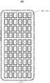
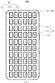
- one or more display pixels 11 and the image capturing pixels 21 may be arranged in a crossed manner in the display row in the display area 101 (e.g., as shown in FIG. 2 ).
- one or more image capturing pixels 21 may be arranged between every two adjacent display pixels 11 in the same display row.
- one or more display pixels 11 may be arranged between every two adjacent image capturing pixels 21 in the same display row.
- one or more display pixels 11 and the image capturing pixels 21 may be arranged in a crossed manner in the display column (e.g., as shown in FIG. 1 ).
- one or more image capturing pixels 21 may be arranged between every two adjacent display pixels 11 in the same display column.
- one or more display pixels 11 may be arranged between every two adjacent image capturing pixels 21 on the same display column.
- a number of display pixels 11 and a number of image capturing pixels 21 may be arranged in any arrangement and combination manner within the display area 101.
- each display pixel 11 includes at least three sub-display pixels 111 and each image capturing pixel 21 includes at least three sub-image capturing pixels 211.
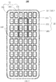
- a number of sub-display pixels 111 and a number of sub-image capturing pixels 211 are arranged in a crossed manner in the display area 101 (e.g., as shown in FIG. 3 ).
- the "crossed manner” means that a number of sub-display pixels 111 and a number of sub-image capturing pixels 211 are arranged as an interleaved array in the display area 101.
- one or more sub-display pixels 111 and the sub-image capturing pixels 211 may be arranged in a crossed manner in the display row.
- one or more sub-image capturing pixels 211 may be arranged between every two adjacent sub-display pixels 111 in the same display row.
- one or more sub-display pixels 111 may be arranged between every two adjacent sub-image capturing pixels 211 in the same display row.
- one or more sub-display pixels 111 and the sub-image capturing pixels 211 may be arranged in a crossed manner in the display column. For example, one or more sub-image capturing pixels 211 may be arranged between every two adjacent sub-display pixels 111 in the same display column. Similarly, one or more sub-display pixels 111 may be arranged between every two adjacent sub-image capturing pixels 211 in the same display column.
- a number of display pixels 11 and a number of image capturing pixels 21 are arranged on the entire display screen 10, so that the whole display screen 10 can display normally and has an image capturing function. Therefore, the area of the image capturing area and the area of the display area is the same, thereby achieving a large image capturing area.
- the display area 101 of the display screen 10 includes an sub-area 102 that is smaller than that of the display area 101.
- a number of image capturing pixels 21 are arranged in the sub-area 102 and a number of display pixels 11 and a number of image capturing pixels 21 arranged in a crossed manner in the sub-area 102.
- a number of display pixels 11 are arranged as an array in the display area 101, and a number of image capturing pixels 21 are arranged as an array in the sub-area 102 (also referred to as the image capturing area here), which is located in one or more gaps among the display pixels 11.
- a number of display pixels 11 and a number of image capturing pixels 21 are arranged in a crossed manner in the sub-area 102.
- the "crossed manner” means that a number of display pixels 11 and a number of image capturing pixels 21 are arranged an interleaved manner in the sub-area 102.
- one or more display pixels 11 and one or more image capturing pixels 21 may be arranged in a crossed manner in the display row in the sub-area 102 (e.g., as shown in FIG. 4 ).
- one or more image capturing pixels 21 may be arranged between every two adjacent display pixels 11 in the same display row.
- one or more display pixels 11 may be arranged between every two adjacent image capturing pixels 21 in the same display row.
- one or more display pixels 11 and the image capturing pixels 21 may be arranged in a crossed manner in the display column.
- one or more image capturing pixels 21 may be arranged between every two adjacent display pixels 11 in the same display column.
- one or more display pixels 11 may be arranged between every two adjacent image capturing pixels 21 in the same display column.
- each display pixel 11 includes at least three sub-display pixels 111 and each image capturing pixel 21 includes at least three sub-image capturing pixels 211.
- a number of sub-display pixels 111 and a number of sub-image capturing pixels 211 are arranged in a crossed manner in the sub-area 102.
- the "cross manner" means that a number of sub-display pixels 111 and a number of sub-image capturing pixels 211 are arranged as an interleaved array.
- one or more sub-display pixels 111 and one or more sub-image capturing pixels 211 may be arranged in a crossed manner in the display row.
- one or more sub-image capturing pixels 211 may be arranged between every two adjacent sub-display pixels 111 in the same display row.
- one or more sub-display pixels 111 may be arranged between every two adjacent sub-image capturing pixels 211 in the same display row.
- one or more sub-display pixels 111 and the sub-image capturing pixels 211 may be arranged in a crossed manner in the display column. For example, one or more sub-image capturing pixels 211 may be arranged between every two adjacent sub-display pixels 111 in the same display column. Similarly, one or more sub-display pixels 111 may be arranged between every two adjacent sub-image capturing pixels 211 in the same display column.
- a sub-area 102 within the display area 101 is provided on the display screen 10 and may be used for image capturing. Therefore, the number of the image capturing pixels 21 may be reduced and the cost may be reduced.
- the rest of the display screen 10 may also normally display, so that the capturing of the image and the display of the screen are not obstructed. Therefore, the user experience may be improved.
- a number of sub-areas 102 may be arranged on the display screen 10, for example, there may be two or more sub-areas 102 for imaging capturing.
- an electronic device includes a display screen.
- the display screen includes a number of display pixels in a display area and a number of image capturing pixels in an image capturing area.
- the image capturing area is arranged in a gap between a number of display pixels.
- the display screen can operate in a display mode or an image capturing mode.
- the image capturing area and the display area are two independent area.
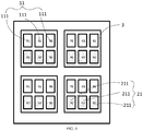
- a display pixel of the plurality of display pixels 11 and an image capturing pixel of image capturing pixel 21 are integrated into a composite pixel 3.
- the display pixel 11 includes at least three sub-display pixels 111 and the image capturing pixel 21 includes at least three sub-image capturing pixels 211.
- the sub-display pixels 111 and the sub-image capturing pixels 21 are located in different display row or display column.
- a display pixel 11 and an image capturing pixel 21 are integrated into a composite pixel 3, so that the integration level of the chip may be improved.
- the arrangement of the pixel 11 and the image capturing pixel 21 may be conveniently design, the manufacturing difficulty is reduced while the efficiency is improved.
- the display screen may be a MicroLED (micro light emitting diode) and a micro-image capturing pixel is simultaneously implanted into the screen, so that a novel screen integrating display and image capturing is achieved.
- the image capturing pixels may be arranged in the gaps.
- the image capturing pixels may be arranged in a certain area of the screen and may form an array, the display screen is operable in a display mode (through the MicroLED sub-pixels) and/or an image capturing mode (photographing/videotaping through image capturing pixels).
- an electronic device 100 comprises the above mentioned display screen 10 and a processor.
- the processor configured to control the display screen to operate in at least one of the display mode or the image capturing mode.
- the electronic device 100 is provided with the display screen 10, so a camera and other structures used for image capturing may be omitted.
- the front camera of the electronic device 100 may be completely omitted. Therefore, the space on display screen that is occupied by the image capturing structure may be greatly reduced, thereby greatly improving the screen-to-body ratio of the electronic device.
- the electronic device 100 is a mobile phone. Further, the mobile phone may further comprise a radio frequency circuit, a memory, an input unit, a wireless fidelity (WIFI) module, a sensor, an audio circuit, a processor, a power supply and the like.
- WIFI wireless fidelity
- the radio frequency circuit may be used for receiving and transmitting signals during receiving and sending information or communication. Particularly, the radio frequency circuit receives the downlink information of the base station for the processor to process and sends uplink data of the mobile phone to the base station.
- the RF circuit includes, but is not limited to, an antenna, at least one amplifier, a coupler, a low-noise amplifier, a duplexer and the like.
- the radio frequency circuit may be in communication with the network and other devices through wireless communication.
- the wireless communication may use any communication standard or protocol includes, but is not limited to, a global system for mobile communication(GSM), general packet radio service(GPRS), code division multiple access(CDMA), wideband code division multiple access (WCDMA), long term evolution (LTE), e-mail, short messaging service (SMS) and the like.
- GSM global system for mobile communication
- GPRS general packet radio service
- CDMA code division multiple access
- WCDMA wideband code division multiple access
- LTE long term evolution
- SMS short messaging service
- the memory may be used for storing a software program and a module.
- the processor is used for executing the software program stored in the memory and the module, so that various functional applications and data processing of the mobile phone are carried out.
- the memory may mainly include a storage program area and a storage data area, wherein the storage program area may store an operating system, at least one application program for function (such as a sound playing function, an image playing function and the like).
- the storage data area may store data (such as audio data, telephone book and the like) created according to the use of the mobile phone.
- the memory may include a high-speed random access memory and may also include a non-volatile memory, such as at least one magnetic disk storage device, a flash memory device or other volatile solid state memory devices.
- the input unit may be used for receiving input digital or character information and generating key signals related to user setting and function control of the mobile phone.
- the input unit may include a touch panel and other input devices.
- the touch panel also referred to as a touch screen, may collect a touch operation (such as a user uses fingers, touch pen and other suitable objects or accessories on the touch panel or in the vicinity of the touch panel) and drive the corresponding connecting device according to a preset program.
- the touch panel may include a touch detection device and a touch controller. The touch detection device detects the touch orientation of a user and detects a signal brought by the touch operation and transmits the signal to the touch controller.
- the touch controller receives touch information from the touch detection device, converts the touch information into contact coordinates, sends to the processor, receives a command sent by the processor and executing the command.
- a touch panel may be resistance-type touch panel, capacitive-type touch panel, infrared-type touch panel, surface-sound-waves-type touch panel and the like.
- the input unit may also include other input devices. Specifically, other input devices may include, but is not limited to, a physical keyboard, a function key (such as a volume control key, a switch button and the like)), a trackball, a mouse, an operating rod and the like.
- the mobile phone may also include an attitude sensor, a light sensor and other sensors.
- the gesture sensor may refer to a motion sensor and may be one of the motion sensors as a gravity sensor.
- the gravity sensor is made of cantilever displacement device with elastic sensitive element. An electric contact is driven by an energy storage spring made of an elastic sensitive element, so that the change of the gravity into an electric signal may be realized.
- the accelerometer sensor may be enumerated as the other one of the motion sensors.
- the accelerometer sensor may detect the acceleration in all directions (generally three axes), may detect the gravity and the direction during the static state. It may be used for identifying the application of a mobile phone through the state of the mobile phone and it may having vibration identification functions (such as pedometer, knocking) and the like.
- a sensor may contains a pressure gauge, a hygrometer, a thermometer, an infrared sensor and the like.
- the light sensor may include an ambient light sensor and a proximity sensor.
- the ambient light sensor may adjust the brightness of the display screen according to the brightness of ambient light and the proximity sensor.
- the display screen may be switched off according to the proximity sensor when the mobile phone is moved to the ear.
- the audio circuit, the loudspeaker and the microphone may provide an audio interface between the user and the mobile phone.
- the audio circuit may convert the received audio data into electrical signals and transmit it to a loudspeaker.
- the loudspeaker convert the electrical signals into a sound signal and output the sound signal.
- the microphone is used for converting the collected sound signal into an electric signal and the audio circuit receives the electric signal and converts it into audio data. Then the audio data is outputted to a processor to process and transmitted to the other mobile phone via the radio frequency circuit, or the audio data is outputted to the memory for further processing.
- the processor is a control center of the electronic device 100.
- the processor is installed on the circuit board assembly, and connects all parts of the whole electronic device 100 through various interfaces and circuits.
- the processor monitor the electronic device by running or executing the software programs and/or modules stored in the memory, calling the data stored in the memory, processing data and executing function of the electronic device 100.
- the processor may include one or more processing units.
- the processor may be integrated with an application processor and a modulation and demodulation processor.
- the application processor is mainly used for processing an operating system, a user interface, an application program and the like, while the modulation and demodulation processor is mainly used for processing wireless communication.
- the power supply may be logically connected with the processor through the power management system, so that the functions of management, charging, discharging, power consumption management and the like are realized through the power management system.
- the electronic device 100 may also include a Bluetooth module, a sensor (such as a gesture sensor, a light sensor, a barometer, a hygrometer, a thermometer, an infrared sensor and the like).
- the mobile phone is only one example of the electronic device 100, and the present application is not limited to it.
- the electronic device 100 may also be a personal computer and the like.
Landscapes
- Engineering & Computer Science (AREA)
- Chemical & Material Sciences (AREA)
- Theoretical Computer Science (AREA)
- Physics & Mathematics (AREA)
- Computer Hardware Design (AREA)
- General Physics & Mathematics (AREA)
- Inorganic Chemistry (AREA)
- Sustainable Development (AREA)
- Life Sciences & Earth Sciences (AREA)
- Signal Processing (AREA)
- Crystallography & Structural Chemistry (AREA)
- Control Of Indicators Other Than Cathode Ray Tubes (AREA)
- Control Of El Displays (AREA)
- User Interface Of Digital Computer (AREA)
- Telephone Function (AREA)
- Controls And Circuits For Display Device (AREA)
- Devices For Indicating Variable Information By Combining Individual Elements (AREA)
- Led Device Packages (AREA)
- Transforming Light Signals Into Electric Signals (AREA)
Abstract
Description
- The present disclosure relates to the field of electronic technology, and more particularly to a display screen and an electronic device.
- In related art, an image sensor is usually arranged on the top of a screen. Since the image sensor and the screen are separated component, the arrangement of the image sensor can occupy the area of the screen, so the proportion of the space for arranging the display screen in the electronic device is small and the screen-to-body ratio of the electronic device is low.
- In an aspect of the present disclosure, a display screen is provided. The display screen includes a number of display pixels arranged on a display area of the display screen and a number of image capturing pixels arranged in gaps between the number of display pixels, wherein the display screen is operable in a display mode or an image capturing mode, and wherein the display screen is configured to selectively activate the number of display pixels or the number of image capturing pixels based on which mode it operates in.
- In another aspect of the present disclosure, an electronic device is provided. The electronic device includes a display screen. The display screen includes a number of display pixels arranged on a display area of the display screen and a number of image capturing pixels arranged in gaps between the number of display pixels, wherein the display screen is operable in a display mode or an image capturing mode; and a processor configured to selectively activate the number of display pixels or the number of image capturing pixels of the display screen based on a mode that the display screen operates in.
- In yet another aspect of the present disclosure, an electronic device is provided. The electronic device includes a display screen. The display screen includes a number of display pixels in a display area and a number of image capturing pixels in a sub-area, wherein the sub-area is positioned in one or more gaps between the number of display pixels, and wherein the display screen is operable in a display mode or an image capturing mode; and a processor configured to control the display screen to operate in at least one of the display mode or the image capturing mode.
- According to some embodiments of the disclosure, the display pixel and the image capturing pixel are integrated into a
display screen 10, so that the display screen support both display mode and image capturing mode. A camera and other structures used for image capturing may be omitted for electronic device with such display screen, for example, the front camera of the electronic device may be completely omitted. Therefore, the space on display screen that is occupied by the image capturing structure may be greatly reduced, thereby greatly improving the screen-to-body ratio of the electronic device. - The above and/or additional aspects of the present disclosure and the advantages of the present disclosure will become apparent and easily understood from the following description of the embodiments taken in conjunction with the accompanying drawings, in which:
-
FIG. 1 is a structural schematic diagram of an electronic device according to one embodiment of the present disclosure. -
FIG. 2 is a structural schematic diagram of an electronic device according to one embodiment of the present disclosure. -
FIG. 3 is a structural schematic diagram of an electronic device according to another embodiment of the present disclosure. -
FIG. 4 is a structural schematic diagram of an electronic device according to yet another embodiment of the disclosure. -
FIG. 5 is a structural schematic diagram of an electronic device according to additional embodiment of the disclosure. -
FIG. 6 is a structural schematic diagram of a display screen or a local structure diagram of a display screen according to one embodiment of the disclosure. -
FIG. 7 is a structural schematic diagram of a display screen or a local structure diagram of a display screen according to another embodiment of the disclosure. -
display screen 10;display area 101; asub-area 102 that can be used for image capturing;display pixel 11;sub-display pixel 111;image capturing pixel 21; sub-image capturingpixel 211;composite pixel 3;electronic device 100. - Embodiments of the present disclosure will be described in detail and examples of the embodiments will be illustrated in the accompanying drawing. The same or similar elements and the elements having same or similar functions are denoted by like reference numerals throughout the descriptions. The embodiments described herein with reference to the drawings are explanatory, which aim to illustrate the present disclosure, but shall not be construed to limit the present disclosure.
- In an aspect of the present disclosure, a display screen is provided. The display screen includes a number of display pixels arranged on a display area of the display screen and a number of image capturing pixels arranged in gaps between the number of display pixels, wherein the display screen is operable in a display mode or an image capturing mode, and wherein the display screen is configured to selectively activate the number of display pixels or the number of image capturing pixels based on which mode it operates in.
- In an embodiment, the number of image capturing pixels and the number of display pixels are operated in a mutually exclusive manner.
- In an embodiment, each display pixel comprises at least three sub-display pixels.
- In an embodiment, each sub-display pixel of each display pixel displays different color.
- In an embodiment, each sub-display pixel of each display pixel displays a same color, and wherein all except one of the sub-display pixel of each display pixel are provided with one or more coating films or light filters such that a light color emitted by each sub-display pixel is different.
- In an embodiment, each sub-display pixel of each display pixel displays a same color, and wherein each sub-display pixels is provided with a coating film or a light filter such that a light color emitted by each sub-display pixel is different.
- In an embodiment, each image capturing pixel comprises at least three sub-image capturing pixels, and wherein each sub-image capturing pixel is used for collecting different color.
- In an embodiment, each sub-image capturing pixel in each image capturing pixel is provided with a coating film or a light filter corresponding to the color to be collected by the sub-image capturing pixel.
- In an embodiment, a number of display pixels and a number of image capturing pixels are arranged as an interleaved array in the display area.
- In an embodiment, each display pixel comprises at least three sub-display pixels and each image capturing pixel comprises at least three sub-image capturing pixels, and wherein the at least three sub-display pixels and the at least three sub-image capturing pixels are arranged as an interleaved array in the display area.
- In an embodiment, a display area of the display screen further includes a sub-area that is smaller than that of the display area, and wherein at least a subset of the number of display pixels and the number of image capturing pixels are arranged in an interleaved manner in the sub-area.
- In an embodiment, each display pixel comprises at least three sub-display pixels and each image capturing pixel comprises at least three sub-image capturing pixels, and wherein the at least three sub-display pixels and the at least three sub-image capturing pixels are arranged in an interleaved manner in the sub-area.
- In an embodiment, a display pixel of the number of display pixels and an image capturing pixel of the number of image capturing pixels are integrated into a composite pixel, the display pixel comprising at least three sub-display pixels, the image capturing pixel comprising at least three sub-image capturing pixels, and wherein the at least three sub-display pixels and the at least three sub-image capturing pixels are located in a different display row or display column in the composite pixel.
- In another aspect of the present disclosure, an electronic device is provided. The electronic device includes a display screen. The display screen includes a number of display pixels arranged on a display area of the display screen and a number of image capturing pixels arranged in gaps between the number of display pixels, wherein the display screen is operable in a display mode or an image capturing mode; and a processor configured to selectively activate the number of display pixels or the number of image capturing pixels of the display screen based on a mode that the display screen operates in.
- In an embodiment, the number of display pixels and the number of image capturing pixels are arranged on the entire display screen.
- In an embodiment, the display area of the
display screen 10 includes a sub-area that is smaller than the display area, and wherein the number of display pixels and the number of image capturing pixels are arranged in an interleaved manner in the sub-area.. - In an embodiment, each display pixel comprises at least three sub-display pixels, and wherein each image capturing pixel comprises at least three sub-image capturing pixels each used for collecting a different color.
- In yet another aspect of the present disclosure, an electronic device is provided. The electronic device includes a display screen. The display screen includes a number of display pixels in a display area and a number of image capturing pixels in a sub-area, wherein the sub-area is positioned in one or more gaps between the number of display pixels, and wherein the display screen is operable in a display mode or an image capturing mode; and a processor configured to control the display screen to operate in at least one of the display mode or the image capturing mode.
- In an embodiment, wherein a number of image capturing pixels perform image capturing while a number of display pixels display an image.
- In an embodiment, the display screen is configured to selectively activate the number of display pixels or the number of image capturing pixels based on which mode it operates in.
- According to one aspect of the present disclosure, a
display screen 10 will be described below with reference toFIGS. 1-6 . - According to one embodiment of the present disclosure, the
display screen 10 comprises a number ofdisplay pixels 11 and a number ofimage capturing pixels 21. - A number of
display pixels 11 are tiled on thedisplay area 101 of thewhole display screen 10. A number ofimage capturing pixels 21 are arranged in gaps between a number ofdisplay pixels 11. - The
display screen 10 can be in a display mode and an image capturing mode. When thedisplay screen 10 is in a display mode, thedisplay pixel 11 is switched on while theimage capturing pixel 21 is switched off. When thedisplay screen 10 is in an image capturing mode, theimage capturing pixel 21 is switched on while thedisplay pixel 11 is switched off. - According to an embodiment of the disclosure, the
display pixel 11 and theimage capturing pixel 21 are integrated into adisplay screen 10, so that the display screen support both display mode and image capturing mode. A camera and other structures used for image capturing may be omitted for electronic device with such display screen, for example, the front camera of the electronic device may be completely omitted. Therefore, the space on display screen that is occupied by the image capturing structure may be greatly reduced, thereby greatly improving the screen-to-body ratio of the electronic device. - According to one embodiment of the present disclosure, a
display screen 10 will be described in detail below with reference toFIGS. 1-6 . - In an embodiment of the present disclosure, each
display pixel 11 includes at least threesub-display pixels 111. - In some embodiments of the present disclosure, referring to
FIG. 2 , eachdisplay pixel 11 includes threesub-display pixels 111. Optionally, the threesub-display pixels 111 may be aR1 sub-display pixel 111, aG1 sub-display pixel 111 and aB1 sub-display pixel 111. TheR1 sub-display pixel 111 is ared sub-display pixel 111, theG1 sub-display pixel 111 is agreen sub-display pixel 111 and theB1 sub-display pixel 111 is a bluesub-display pixel 111. The value of the three colors of the threesub-display pixels 111 is adjusted, so as to change the color and the brightness displayed by each pixel point. That is, in the present embodiment, thedisplay screen 10 may use a RGB color standard. - Of course, the disclosure is not limited to this. In another embodiment of the present disclosure, each
display pixel 11 includes four sub-display pixels 111 (not shown). Optionally, the foursub-display pixels 111 may be aR1 sub-display pixel 111, aG1 sub-display pixel 111, a B1sub-display pixel 111 and aW1 sub-display pixel 111. TheR1 sub-display pixel 111 is ared sub-display pixel 111, theG1 sub-display pixel 111 is agreen sub-display pixel 111, theB1 sub-display pixel 111 is a bluesub-display pixel 111 and theW1 sub-display pixel 111 is awhite sub-display pixel 111. The value of the four colors of the foursub-display pixels 111 is adjusted, so as to control the color and the brightness displayed by each pixel point. That is, in the present embodiment, thedisplay screen 10 may use a RGBW color standard. - In addition, in another embodiment of the present disclosure, the four
sub-display pixels 111 in the above example may be aC1 sub-display pixel 111, aM1 sub-display pixel 111, aY1 sub-display pixel 111 and aK1 sub-display pixel 111. TheC1 sub-display pixel 111 is acyan sub-display pixel 111, theM1 sub-display pixel 111 is a magentasub-display pixel 111, theY1 sub-display pixel 111 is ayellow sub-display pixel 111 and theK1 sub-display pixel 111 is ablack sub-display pixel 111. The value of the four colors of the foursub-display pixels 111 is adjusted, so as to adjust the color and the brightness displayed by each pixel point. That is, in the present embodiment, thedisplay screen 10 may use a CMYK color standard. - In some embodiments of the present disclosure, each
sub-display pixel 111 in eachdisplay pixel 11 may display different color. - For example, for each
display pixel 11 with threesub-display pixels 111, each of the threesub-display pixel 111 may display different color. For example, in an RGB color standard, theR1 sub-display pixel 111 may be asub-display pixel 111 capable of displaying red color, theG1 sub-display pixel 111 may be asub-display pixel 111 capable of displaying green color, theB1 sub-display pixel 111 may be asub-display pixel 111 capable of displaying blue color. - Of course, the present disclosure is not limited to this, each
sub-display pixel 111 of each display pixel may display the same color. In some embodiments, except one of the sub-display pixel of each display pixel, the remaining sub-display pixels are provided with coating films or light filters respectively, so that the light color emitted by each sub-display pixel is different. - In some embodiments, in the RGB color standard, the
R1 sub-display pixel 111, theG1 sub-display pixel 111 and theB1 sub-display pixel 111 may besub-display pixels 111 with the same color. For example, the threesub-display pixels 111 may all besub-display pixels 111 capable of displaying blue color. TheR1 sub-display pixel 111 may be provided with a coating film or a light filter, so that the light emitted by theR1 sub-display pixel 111 is red, theG1 sub-display pixel 111 may be provided with a coating film or a light filter, so that the light emitted by theG1 sub-display pixel 111 is green. - In an embodiment, each sub-display pixel of each display pixel displays the same color. Each sub-display pixel is provided with a coating film or a light filter, so that the light color emitted by each sub-display pixel is different.
- Of course, there are similar embodiments for a
display screen 10 using a RGBW color standard and a CMYK color standard as described above, and is not described in detail herein. - In an embodiment of the present disclosure, each
image capturing pixel 21 includes at least threesub-image capturing pixels 211. Eachsub-image capturing pixel 211 is used for collecting a different color, and then the color value collected by theimage capturing pixel 21 is obtained through calculation. - In some embodiments, each
image capturing pixel 21 includes threesub-image capturing pixels 211. The threesub-image capturing pixels 211 may be a R2sub-image capturing pixel 211, a G2sub-image capturing pixel 211 and a B2sub-image capturing pixel 211. The R2 sub-image capturingpixel 211 is used for collecting red color value, the G2sub-image capturing pixel 211 is used for collecting green color value, the B2sub-image capturing pixel 211 is used for collecting blue color value. The values of the three colors of the threesub-image capturing pixel 211 are collected to acquire the color and the brightness of each pixel point. That is, in the present embodiment, theimage capturing pixel 21 may use a RGB color standard to collect image. - Of course, the present disclosure is not limited to this, in another embodiment of the present disclosure, each
image capturing pixel 21 comprises four sub-image capturing pixels 211 (not shown), and the four sub-image capturingpixels 211 may be a R2sub-image capturing pixel 211, a G2sub-image capturing pixel 211, a B2sub-image capturing pixel 211 and a W2image capturing pixel 21. The R2 sub-image capturingpixel 211 is used for collecting red color value, the G2sub-image capturing pixel 211 is used for collecting green color value, the B2sub-image capturing pixel 211 is used for collecting blue color value and the W2image capturing pixel 21 is used for collecting white color value. The value of the four colors of the foursub-image capturing pixel 211 is collected to acquire the color and the brightness of each pixel point. That is, in the present embodiment, theimage capturing pixel 21 may use a RGBW color standard to collect image. - In addition, in another embodiment of the present disclosure, the four sub-image capturing
pixels 211 may be a C2sub-image capturing pixels 211, a M2sub-image capturing pixel 211, a Y2sub-image capturing pixel 211 and a K2sub-image capturing pixel 211. The C2 sub-image capturingpixel 211 is a cyansub-image capturing pixel 211, the M2sub-image capturing pixel 211 is a magentasub-image capturing pixel 211, the Y2sub-image capturing pixel 211 is a yellowsub-image capturing pixel 211 and the K2sub-image capturing pixel 211 is a blacksub-image capturing pixel 211. The value of the four colors of the foursub-image capturing pixel 211 is collected to acquire the color and the brightness of each pixel point. That is, in the present embodiment, theimage capturing pixel 21 may use a CMYK color standard to collect image. - In some embodiments of the present disclosure, each
sub-image capturing pixel 211 of eachimage capturing pixel 21 is provided with a coating film or a light filter corresponding to the color to be collected by theimage capturing pixel 211. Take theimage capturing pixel 21 that uses a RGB color standard for image capturing as an example, the R2sub-image capturing pixel 211 is provided with a red light filter which passes through the red wavelength, the G2sub-image capturing pixel 211 is provided with a green light filter which passes through the green wavelength and the B2sub-image capturing pixel 211 is provided with a blue light filter which passes through the blue wavelength. That is, the threesub-image capturing pixels 211 are provided with three light filters respectively. - Of course, the present disclosure is not limited to this, and the three
sub-image capturing pixels 211 may also be provided with one light filter with different colors in different regions. - Of course, there are similar embodiments for a
display screen 10 using a RGBW color standard and a CMYK color standard as described above, and is not described in detail herein. - In some embodiments of the present disclosure, referring to
FIGS. 1-2 , a number ofdisplay pixels 11 and a number ofimage capturing pixels 21 are arranged in a crossed manner indisplay area 101. - The "crossed manner" means that a number of
display pixels 11 and a number ofimage capturing pixels 21 are arranged in an interleaved manner in thedisplay area 101. In some embodiments, one ormore display pixels 11 and theimage capturing pixels 21 may be arranged in a crossed manner in the display row in the display area 101 (e.g., as shown inFIG. 2 ). For example, one or moreimage capturing pixels 21 may be arranged between every twoadjacent display pixels 11 in the same display row. Similarly, one ormore display pixels 11 may be arranged between every two adjacentimage capturing pixels 21 in the same display row. In some embodiments, one ormore display pixels 11 and theimage capturing pixels 21 may be arranged in a crossed manner in the display column (e.g., as shown inFIG. 1 ). For example, one or moreimage capturing pixels 21 may be arranged between every twoadjacent display pixels 11 in the same display column. Similarly, one ormore display pixels 11 may be arranged between every two adjacentimage capturing pixels 21 on the same display column. - In some embodiments of the present disclosure, a number of
display pixels 11 and a number ofimage capturing pixels 21 may be arranged in any arrangement and combination manner within thedisplay area 101. - In some embodiments of the present disclosure, each
display pixel 11 includes at least threesub-display pixels 111 and eachimage capturing pixel 21 includes at least threesub-image capturing pixels 211. A number ofsub-display pixels 111 and a number of sub-image capturingpixels 211 are arranged in a crossed manner in the display area 101 (e.g., as shown inFIG. 3 ). - The "crossed manner" means that a number of
sub-display pixels 111 and a number of sub-image capturingpixels 211 are arranged as an interleaved array in thedisplay area 101. In some embodiments, one or moresub-display pixels 111 and thesub-image capturing pixels 211 may be arranged in a crossed manner in the display row. For example, one or moresub-image capturing pixels 211 may be arranged between every two adjacentsub-display pixels 111 in the same display row. Similarly, one or moresub-display pixels 111 may be arranged between every two adjacentsub-image capturing pixels 211 in the same display row. In some embodiments, one or moresub-display pixels 111 and thesub-image capturing pixels 211 may be arranged in a crossed manner in the display column. For example, one or moresub-image capturing pixels 211 may be arranged between every two adjacentsub-display pixels 111 in the same display column. Similarly, one or moresub-display pixels 111 may be arranged between every two adjacentsub-image capturing pixels 211 in the same display column. - Thus, a number of
display pixels 11 and a number ofimage capturing pixels 21 are arranged on theentire display screen 10, so that thewhole display screen 10 can display normally and has an image capturing function. Therefore, the area of the image capturing area and the area of the display area is the same, thereby achieving a large image capturing area. - In some embodiments of the present disclosure, referring to
FIGS. 3-4 , thedisplay area 101 of thedisplay screen 10 includes an sub-area 102 that is smaller than that of thedisplay area 101. A number ofimage capturing pixels 21 are arranged in thesub-area 102 and a number ofdisplay pixels 11 and a number ofimage capturing pixels 21 arranged in a crossed manner in thesub-area 102. - In some embodiments of the present disclosure, a number of
display pixels 11 are arranged as an array in thedisplay area 101, and a number ofimage capturing pixels 21 are arranged as an array in the sub-area 102 (also referred to as the image capturing area here), which is located in one or more gaps among thedisplay pixels 11. In some embodiments, as shown inFIG. 4 , a number ofdisplay pixels 11 and a number ofimage capturing pixels 21 are arranged in a crossed manner in thesub-area 102. - The "crossed manner" means that a number of
display pixels 11 and a number ofimage capturing pixels 21 are arranged an interleaved manner in thesub-area 102. In some embodiments, one ormore display pixels 11 and one or moreimage capturing pixels 21 may be arranged in a crossed manner in the display row in the sub-area 102 (e.g., as shown inFIG. 4 ). For example, one or moreimage capturing pixels 21 may be arranged between every twoadjacent display pixels 11 in the same display row. Similarly, one ormore display pixels 11 may be arranged between every two adjacentimage capturing pixels 21 in the same display row. In some embodiments, one ormore display pixels 11 and theimage capturing pixels 21 may be arranged in a crossed manner in the display column. For example, one or moreimage capturing pixels 21 may be arranged between every twoadjacent display pixels 11 in the same display column. Similarly, one ormore display pixels 11 may be arranged between every two adjacentimage capturing pixels 21 in the same display column. - In some embodiments of the present disclosure, each
display pixel 11 includes at least threesub-display pixels 111 and eachimage capturing pixel 21 includes at least threesub-image capturing pixels 211. A number ofsub-display pixels 111 and a number of sub-image capturingpixels 211 are arranged in a crossed manner in thesub-area 102. - The "cross manner" means that a number of
sub-display pixels 111 and a number of sub-image capturingpixels 211 are arranged as an interleaved array. In some embodiments, one or moresub-display pixels 111 and one or moresub-image capturing pixels 211 may be arranged in a crossed manner in the display row. For example, one or moresub-image capturing pixels 211 may be arranged between every two adjacentsub-display pixels 111 in the same display row. Similarly, one or moresub-display pixels 111 may be arranged between every two adjacentsub-image capturing pixels 211 in the same display row. In some embodiments, one or moresub-display pixels 111 and thesub-image capturing pixels 211 may be arranged in a crossed manner in the display column. For example, one or moresub-image capturing pixels 211 may be arranged between every two adjacentsub-display pixels 111 in the same display column. Similarly, one or moresub-display pixels 111 may be arranged between every two adjacentsub-image capturing pixels 211 in the same display column. - Thus, a
sub-area 102 within thedisplay area 101 is provided on thedisplay screen 10 and may be used for image capturing. Therefore, the number of theimage capturing pixels 21 may be reduced and the cost may be reduced. In addition, when theimage capturing pixel 21 performs image capturing function, the rest of thedisplay screen 10 may also normally display, so that the capturing of the image and the display of the screen are not obstructed. Therefore, the user experience may be improved. - Of course, the present disclosure is not limited to this. A number of sub-areas 102 may be arranged on the
display screen 10, for example, there may be two or more sub-areas 102 for imaging capturing. - In one embodiment of the disclosure, referring to
FIG. 5 , an electronic device includes a display screen. The display screen includes a number of display pixels in a display area and a number of image capturing pixels in an image capturing area. The image capturing area is arranged in a gap between a number of display pixels. The display screen can operate in a display mode or an image capturing mode. - In one embodiment, the image capturing area and the display area are two independent area.
- In one embodiment of the disclosure, referring to
FIGS.6-7 , a display pixel of the plurality ofdisplay pixels 11 and an image capturing pixel ofimage capturing pixel 21 are integrated into acomposite pixel 3. Thedisplay pixel 11 includes at least threesub-display pixels 111 and theimage capturing pixel 21 includes at least threesub-image capturing pixels 211. In thecomposite pixel 3, thesub-display pixels 111 and thesub-image capturing pixels 21 are located in different display row or display column. Adisplay pixel 11 and animage capturing pixel 21 are integrated into acomposite pixel 3, so that the integration level of the chip may be improved. The arrangement of thepixel 11 and theimage capturing pixel 21 may be conveniently design, the manufacturing difficulty is reduced while the efficiency is improved. - It should be noted that the display screen may be a MicroLED (micro light emitting diode) and a micro-image capturing pixel is simultaneously implanted into the screen, so that a novel screen integrating display and image capturing is achieved. For a MicroLED display having display pixels, when the MicroLED are micro-scaled to form gaps between the display pixels, the image capturing pixels may be arranged in the gaps. The image capturing pixels may be arranged in a certain area of the screen and may form an array, the display screen is operable in a display mode (through the MicroLED sub-pixels) and/or an image capturing mode (photographing/videotaping through image capturing pixels).
- In one embodiment of the disclosure, an
electronic device 100 comprises the above mentioneddisplay screen 10 and a processor. The processor configured to control the display screen to operate in at least one of the display mode or the image capturing mode. - The
electronic device 100 according to the embodiment of the present disclosure is provided with thedisplay screen 10, so a camera and other structures used for image capturing may be omitted. For example, the front camera of theelectronic device 100 may be completely omitted. Therefore, the space on display screen that is occupied by the image capturing structure may be greatly reduced, thereby greatly improving the screen-to-body ratio of the electronic device. - In one embodiment of the present application, referring to
FIGS. 1-7 , theelectronic device 100 is a mobile phone. Further, the mobile phone may further comprise a radio frequency circuit, a memory, an input unit, a wireless fidelity (WIFI) module, a sensor, an audio circuit, a processor, a power supply and the like. - The radio frequency circuit may be used for receiving and transmitting signals during receiving and sending information or communication. Particularly, the radio frequency circuit receives the downlink information of the base station for the processor to process and sends uplink data of the mobile phone to the base station. Generally, the RF circuit includes, but is not limited to, an antenna, at least one amplifier, a coupler, a low-noise amplifier, a duplexer and the like. In addition, the radio frequency circuit may be in communication with the network and other devices through wireless communication. The wireless communication may use any communication standard or protocol includes, but is not limited to, a global system for mobile communication(GSM), general packet radio service(GPRS), code division multiple access(CDMA), wideband code division multiple access (WCDMA), long term evolution (LTE), e-mail, short messaging service (SMS) and the like.
- The memory may be used for storing a software program and a module. The processor is used for executing the software program stored in the memory and the module, so that various functional applications and data processing of the mobile phone are carried out. The memory may mainly include a storage program area and a storage data area, wherein the storage program area may store an operating system, at least one application program for function (such as a sound playing function, an image playing function and the like). The storage data area may store data (such as audio data, telephone book and the like) created according to the use of the mobile phone. In addition, the memory may include a high-speed random access memory and may also include a non-volatile memory, such as at least one magnetic disk storage device, a flash memory device or other volatile solid state memory devices.
- The input unit may be used for receiving input digital or character information and generating key signals related to user setting and function control of the mobile phone. Specifically, the input unit may include a touch panel and other input devices. The touch panel, also referred to as a touch screen, may collect a touch operation (such as a user uses fingers, touch pen and other suitable objects or accessories on the touch panel or in the vicinity of the touch panel) and drive the corresponding connecting device according to a preset program. Optionally, the touch panel may include a touch detection device and a touch controller. The touch detection device detects the touch orientation of a user and detects a signal brought by the touch operation and transmits the signal to the touch controller. The touch controller receives touch information from the touch detection device, converts the touch information into contact coordinates, sends to the processor, receives a command sent by the processor and executing the command. In addition, a touch panel may be resistance-type touch panel, capacitive-type touch panel, infrared-type touch panel, surface-sound-waves-type touch panel and the like. In addition to the touch panel, the input unit may also include other input devices. Specifically, other input devices may include, but is not limited to, a physical keyboard, a function key (such as a volume control key, a switch button and the like)), a trackball, a mouse, an operating rod and the like.
- In some embodiments of the present disclosure, the mobile phone may also include an attitude sensor, a light sensor and other sensors..
- Specifically, the gesture sensor may refer to a motion sensor and may be one of the motion sensors as a gravity sensor. The gravity sensor is made of cantilever displacement device with elastic sensitive element. An electric contact is driven by an energy storage spring made of an elastic sensitive element, so that the change of the gravity into an electric signal may be realized.
- The accelerometer sensor may be enumerated as the other one of the motion sensors. The accelerometer sensor may detect the acceleration in all directions (generally three axes), may detect the gravity and the direction during the static state. It may be used for identifying the application of a mobile phone through the state of the mobile phone and it may having vibration identification functions (such as pedometer, knocking) and the like.
- In one embodiment of the disclosure, a sensor may contains a pressure gauge, a hygrometer, a thermometer, an infrared sensor and the like.
- The light sensor may include an ambient light sensor and a proximity sensor. The ambient light sensor may adjust the brightness of the display screen according to the brightness of ambient light and the proximity sensor. The display screen may be switched off according to the proximity sensor when the mobile phone is moved to the ear.
- The audio circuit, the loudspeaker and the microphone may provide an audio interface between the user and the mobile phone. The audio circuit may convert the received audio data into electrical signals and transmit it to a loudspeaker. The loudspeaker convert the electrical signals into a sound signal and output the sound signal. On the other hand, the microphone is used for converting the collected sound signal into an electric signal and the audio circuit receives the electric signal and converts it into audio data. Then the audio data is outputted to a processor to process and transmitted to the other mobile phone via the radio frequency circuit, or the audio data is outputted to the memory for further processing.
- The processor is a control center of the
electronic device 100. The processor is installed on the circuit board assembly, and connects all parts of the wholeelectronic device 100 through various interfaces and circuits. The processor monitor the electronic device by running or executing the software programs and/or modules stored in the memory, calling the data stored in the memory, processing data and executing function of theelectronic device 100. Alternatively, the processor may include one or more processing units. Alternatively, the processor may be integrated with an application processor and a modulation and demodulation processor. The application processor is mainly used for processing an operating system, a user interface, an application program and the like, while the modulation and demodulation processor is mainly used for processing wireless communication. - The power supply may be logically connected with the processor through the power management system, so that the functions of management, charging, discharging, power consumption management and the like are realized through the power management system. Although not shown, the
electronic device 100 may also include a Bluetooth module, a sensor (such as a gesture sensor, a light sensor, a barometer, a hygrometer, a thermometer, an infrared sensor and the like). - It is to be understood that the mobile phone is only one example of the
electronic device 100, and the present application is not limited to it. For example, theelectronic device 100 may also be a personal computer and the like. - In the description of the specification, reference is made to the term "one embodiment", "some embodiments" or "for example" and the like are intended to refer to specific feature, structure, material or characteristic included in at least one embodiment or example of the present disclosure. In the specification, the schematic expression of the above terms does not necessarily refer to the same embodiment or example. Moreover, the specific feature, structure, material or characteristic may be combined in any suitable manner in any one or more embodiments or examples.
- While the embodiments of the disclosure have been shown and described, it will be understood by those of ordinary skill in the art that various changes or modifications may be made to these embodiments without departing from the principles and purposes of the present disclosure. The scope of the disclosure is defined by the claims and their equivalents.
Claims (15)
- A display screen (10), characterized by, comprising:a plurality of display pixels (11) arranged on a display area (101) of the display screen; anda plurality of image capturing pixels (21) arranged in gaps between the plurality of display pixels (11), wherein the display screen (10) is operable in a display mode or an image capturing mode, and wherein the display screen (10) is configured to selectively activate the plurality of display pixels (11) or the plurality of image capturing pixels (21) based on which mode it operates in.
- The display screen (10) according to claim 1, wherein the plurality of image capturing pixels (21) and the plurality of display pixels (11) are operated in a mutually exclusive manner.
- The display screen (10) according to claim 1-2, wherein each display pixel (11) comprises at least three sub-display pixels (111).
- The display screen (10) according to claim 3, wherein each sub-display pixel (111) of each display pixel (11) displays different color.
- The display screen (10) according to claim 3, wherein each sub-display pixel (111) of each display pixel (11) displays a same color, and wherein all except one of the sub-display pixel (111) of each display pixel (11) are provided with one or more coating films or light filters such that a light color emitted by each sub-display pixel (111) is different.
- The display screen (10) according to claim 1-2, wherein each image capturing pixel (21) comprises at least three sub-image capturing pixels (211), and wherein each sub-image capturing pixel (211) is used for collecting different color.
- The display screen (10) according to claim 6, wherein each sub-image capturing pixel (211) in each image capturing pixel (21) is provided with a coating film or a light filter corresponding to the color to be collected by the sub-image capturing pixel (211).
- The display screen (10) according to claim 1-2, wherein the plurality of display pixels (11) and the plurality of image capturing pixels (21) are arranged as an interleaved array in the display area (101).
- The display screen (10) according to claim 8, wherein each display pixel (11) comprises at least three sub-display pixels (111) and each image capturing pixel (21) comprises at least three sub-image capturing pixels (211), and wherein the at least three sub-display pixels (111) and the at least three sub-image capturing pixels (211) are arranged as an interleaved array in the display area (101).
- The display screen (10) according to claim 1-2, wherein a display area (101) of the display screen (10) further includes a sub-area (102) that is smaller than that of the display area (101), and wherein at least a subset of the plurality of display pixels (11) and the plurality of image capturing pixels (21) are arranged in an interleaved manner in the sub-area (102).
- The display screen (10) according to claim 10, wherein each display pixel (11) comprises at least three sub-display pixels (111) and each image capturing pixel (21) comprises at least three sub-image capturing pixels (211),
and wherein the at least three sub-display pixels (111) and the at least three sub-image capturing pixels (211) are arranged in an interleaved manner in the sub-area (102). - The display screen (10) according to claim 1, wherein a display pixel of the plurality of display pixels (11) and an image capturing pixel of the plurality of image capturing pixels (21) are integrated into a composite pixel (3), the display pixel (11) comprising at least three sub-display pixels (111), the image capturing pixel (21) comprising at least three sub-image capturing pixels (211), and wherein the at least three sub-display pixels (111) and the at least three sub-image capturing pixels (211) are located in a different display row or display column in the composite pixel (3).
- An electronic device (100) with a display screen (10) according to claim 1-12, characterized by comprising:a plurality of display pixels (11) arranged on a display area (101) of the display screen (10); anda plurality of image capturing pixels (21) arranged in gaps between the plurality of display pixels (11),wherein the display screen (10) is operable in a display mode or an image capturing mode; anda processor configured to selectively activate the plurality of display pixels (11) or the plurality of image capturing pixels (21) of the display screen (10) based on a mode that the display screen (10) operates in.
- An electronic device (100) according to claim 13, wherein the display area (101) of the display screen (10) includes a sub-area (102) that is smaller than the display area (101), and wherein the plurality of display pixels (11) and the plurality of image capturing pixels (21) are arranged in an interleaved manner in the sub-area (102).
- An electronic device (100) with a display screen (10) according to claim 1-12, characterized by comprising:a display screen (10) that includes:a plurality of display pixels (11) in a display area (101); anda plurality of image capturing pixels (21) in a sub-area (102),wherein the sub-area (102) is positioned in one or more gaps between the plurality of display pixels (11), and wherein the display screen (10) is operable in a display mode or an image capturing mode; anda processor configured to control the display screen (10) to operate in at least one of the display mode or the image capturing mode.
Applications Claiming Priority (1)
| Application Number | Priority Date | Filing Date | Title |
|---|---|---|---|
| CN201810878085.1A CN109067942B (en) | 2018-08-03 | 2018-08-03 | Display screen and electronic device with same |
Publications (2)
| Publication Number | Publication Date |
|---|---|
| EP3605520A2 true EP3605520A2 (en) | 2020-02-05 |
| EP3605520A3 EP3605520A3 (en) | 2020-02-26 |
Family
ID=64833232
Family Applications (1)
| Application Number | Title | Priority Date | Filing Date |
|---|---|---|---|
| EP19189531.7A Withdrawn EP3605520A3 (en) | 2018-08-03 | 2019-08-01 | Display screen and electronic device |
Country Status (7)
| Country | Link |
|---|---|
| US (1) | US11017706B2 (en) |
| EP (1) | EP3605520A3 (en) |
| JP (1) | JP2021527851A (en) |
| KR (1) | KR20210008426A (en) |
| CN (1) | CN109067942B (en) |
| AU (1) | AU2019315566B2 (en) |
| WO (1) | WO2020025062A1 (en) |
Cited By (1)
| Publication number | Priority date | Publication date | Assignee | Title |
|---|---|---|---|---|
| US11146745B2 (en) | 2019-03-08 | 2021-10-12 | Array Photonics, Inc. | Electronic devices having displays with infrared components behind the displays |
Families Citing this family (1)
| Publication number | Priority date | Publication date | Assignee | Title |
|---|---|---|---|---|
| CN109067942B (en) | 2018-08-03 | 2021-03-16 | Oppo广东移动通信有限公司 | Display screen and electronic device with same |
Citations (2)
| Publication number | Priority date | Publication date | Assignee | Title |
|---|---|---|---|---|
| US9055187B1 (en) * | 2011-12-29 | 2015-06-09 | Intellectual Ventures Fund 79 Llc | Methods, devices, and mediums for displaying an image |
| CN107728361A (en) * | 2017-09-19 | 2018-02-23 | 捷开通讯(深圳)有限公司 | Display panel and electronic equipment with camera function |
Family Cites Families (49)
| Publication number | Priority date | Publication date | Assignee | Title |
|---|---|---|---|---|
| JP3436629B2 (en) * | 1996-01-08 | 2003-08-11 | シャープ株式会社 | Apparatus for display and imaging |
| JP2002314756A (en) * | 2001-04-13 | 2002-10-25 | Sharp Corp | Display device |
| US7184009B2 (en) * | 2002-06-21 | 2007-02-27 | Nokia Corporation | Display circuit with optical sensor |
| JP2005031480A (en) * | 2003-07-08 | 2005-02-03 | Sharp Corp | Display device with imaging function |
| JP4616559B2 (en) * | 2004-01-15 | 2011-01-19 | 大日本印刷株式会社 | Display device and display system |
| US20060007248A1 (en) * | 2004-06-29 | 2006-01-12 | Damoder Reddy | Feedback control system and method for operating a high-performance stabilized active-matrix emissive display |
| US20080144967A1 (en) * | 2004-03-30 | 2008-06-19 | Waterstrike Incorporated | Confidential Viewing System Utilizing Spatial Multiplexing |
| JP2007033789A (en) * | 2005-07-26 | 2007-02-08 | Sony Corp | Display device |
| JP4557228B2 (en) * | 2006-03-16 | 2010-10-06 | ソニー株式会社 | Electro-optical device and electronic apparatus |
| US20080106591A1 (en) * | 2006-11-02 | 2008-05-08 | Border John N | Two way communication system |
| US7697053B2 (en) * | 2006-11-02 | 2010-04-13 | Eastman Kodak Company | Integrated display having multiple capture devices |
| US7714923B2 (en) * | 2006-11-02 | 2010-05-11 | Eastman Kodak Company | Integrated display and capture apparatus |
| US7808540B2 (en) * | 2007-01-09 | 2010-10-05 | Eastman Kodak Company | Image capture and integrated display apparatus |
| JP2009014996A (en) * | 2007-07-04 | 2009-01-22 | Seiko Epson Corp | Image display device |
| US8736587B2 (en) * | 2008-07-10 | 2014-05-27 | Semiconductor Energy Laboratory Co., Ltd. | Semiconductor device |
| US8223188B2 (en) * | 2008-09-16 | 2012-07-17 | Alcatel Lucent | Monitor having integral camera and method of operating the same |
| JP6149339B2 (en) * | 2010-06-16 | 2017-06-21 | 株式会社ニコン | Display device |
| US9286848B2 (en) * | 2010-07-01 | 2016-03-15 | Semiconductor Energy Laboratory Co., Ltd. | Method for driving liquid crystal display device |
| US9158113B2 (en) * | 2012-03-14 | 2015-10-13 | Google Inc. | Integrated display and photosensor |
| US9608727B2 (en) * | 2012-12-27 | 2017-03-28 | Panasonic Intellectual Property Corporation Of America | Switched pixel visible light transmitting method, apparatus and program |
| KR102048925B1 (en) | 2012-12-28 | 2019-11-27 | 삼성디스플레이 주식회사 | Display Device including RGBW Sub-Pixel and Method of Driving thereof |
| US8773573B1 (en) * | 2013-01-15 | 2014-07-08 | Google Inc. | Adjustable lens array with variable optical power |
| KR102081932B1 (en) * | 2013-03-21 | 2020-04-14 | 엘지전자 주식회사 | Display device and method for controlling the same |
| KR102159151B1 (en) * | 2014-02-28 | 2020-09-24 | 삼성디스플레이 주식회사 | Electronic device and display method |
| WO2015143011A1 (en) * | 2014-03-19 | 2015-09-24 | Bidirectional Display Inc. | Image sensor panel and method for capturing graphical information using same |
| JP6472253B2 (en) * | 2014-03-25 | 2019-02-20 | キヤノン株式会社 | Image processing apparatus and control method thereof |
| CN106707576A (en) * | 2015-11-13 | 2017-05-24 | 小米科技有限责任公司 | LCD panel, terminal and photosensory control method thereof |
| CN106710524A (en) | 2015-11-13 | 2017-05-24 | 小米科技有限责任公司 | OLED panel, terminal and photosensitive control method |
| US9749562B2 (en) * | 2015-11-13 | 2017-08-29 | Omnivision Technologies, Inc. | Liquid crystal display and infrared image sensor on silicon |
| KR102473306B1 (en) * | 2015-11-18 | 2022-12-05 | 삼성디스플레이 주식회사 | Display device |
| CN105679798B (en) * | 2016-01-22 | 2019-03-29 | 京东方科技集团股份有限公司 | OLED display device and pixel repair method thereof |
| CN110133899A (en) * | 2018-02-09 | 2019-08-16 | 京东方科技集团股份有限公司 | Pixel arrangement structure, display substrate and display device |
| CN105741748B (en) * | 2016-03-04 | 2019-05-14 | 京东方科技集团股份有限公司 | A display panel, display device and manufacturing method |
| US20170289805A1 (en) * | 2016-03-30 | 2017-10-05 | Motorola Mobility Llc | Embedded active matrix organic light emitting diode (amoled) fingerprint sensor and self-compensating amoled |
| CN107292215A (en) * | 2016-03-31 | 2017-10-24 | 上海箩箕技术有限公司 | Optical fingerprint sensor module |
| CN107292216A (en) * | 2016-03-31 | 2017-10-24 | 上海箩箕技术有限公司 | Optical fingerprint sensor module |
| CN106023818B (en) * | 2016-05-18 | 2019-09-17 | 京东方科技集团股份有限公司 | A kind of driving method of dot structure, display panel and dot structure |
| WO2018023722A1 (en) * | 2016-08-05 | 2018-02-08 | 上海箩箕技术有限公司 | Display module |
| KR102566717B1 (en) * | 2016-12-12 | 2023-08-14 | 삼성전자 주식회사 | Electronic device having a biometric sensor |
| CN108346398A (en) * | 2017-01-24 | 2018-07-31 | 上海珏芯光电科技有限公司 | Its driving method of display driving board device |
| GB2561163B (en) * | 2017-03-30 | 2021-05-12 | Apical Ltd | Control systems and image sensors |
| CN107222664B (en) * | 2017-05-03 | 2020-03-06 | Oppo广东移动通信有限公司 | Camera Modules and Electronic Devices |
| CN107135341B (en) * | 2017-05-03 | 2019-12-27 | Oppo广东移动通信有限公司 | Image sensor, camera module and electronic device |
| CN207338380U (en) | 2017-07-21 | 2018-05-08 | 京东方科技集团股份有限公司 | A kind of electroluminescence display panel and display device |
| US20190064515A1 (en) * | 2017-08-30 | 2019-02-28 | Innolux Corporation | Display device and electronic apparatus using the same |
| CN107749287B (en) * | 2017-11-21 | 2020-03-10 | 武汉天马微电子有限公司 | A display panel and display device |
| CN108054286B (en) * | 2017-12-13 | 2020-03-06 | 合肥鑫晟光电科技有限公司 | Electroluminescent device, display device and manufacturing method thereof |
| CN109067942B (en) | 2018-08-03 | 2021-03-16 | Oppo广东移动通信有限公司 | Display screen and electronic device with same |
| CN111222386B (en) * | 2018-11-27 | 2023-11-10 | 上海耕岩智能科技有限公司 | Fingerprint collection method and device |
-
2018
- 2018-08-03 CN CN201810878085.1A patent/CN109067942B/en active Active
-
2019
- 2019-07-29 US US16/525,341 patent/US11017706B2/en active Active
- 2019-08-01 EP EP19189531.7A patent/EP3605520A3/en not_active Withdrawn
- 2019-08-02 JP JP2020570487A patent/JP2021527851A/en active Pending
- 2019-08-02 WO PCT/CN2019/099104 patent/WO2020025062A1/en not_active Ceased
- 2019-08-02 AU AU2019315566A patent/AU2019315566B2/en active Active
- 2019-08-02 KR KR1020207036173A patent/KR20210008426A/en not_active Ceased
Patent Citations (2)
| Publication number | Priority date | Publication date | Assignee | Title |
|---|---|---|---|---|
| US9055187B1 (en) * | 2011-12-29 | 2015-06-09 | Intellectual Ventures Fund 79 Llc | Methods, devices, and mediums for displaying an image |
| CN107728361A (en) * | 2017-09-19 | 2018-02-23 | 捷开通讯(深圳)有限公司 | Display panel and electronic equipment with camera function |
Cited By (1)
| Publication number | Priority date | Publication date | Assignee | Title |
|---|---|---|---|---|
| US11146745B2 (en) | 2019-03-08 | 2021-10-12 | Array Photonics, Inc. | Electronic devices having displays with infrared components behind the displays |
Also Published As
| Publication number | Publication date |
|---|---|
| CN109067942A (en) | 2018-12-21 |
| JP2021527851A (en) | 2021-10-14 |
| US11017706B2 (en) | 2021-05-25 |
| US20200043397A1 (en) | 2020-02-06 |
| EP3605520A3 (en) | 2020-02-26 |
| CN109067942B (en) | 2021-03-16 |
| KR20210008426A (en) | 2021-01-21 |
| AU2019315566A1 (en) | 2021-01-28 |
| AU2019315566B2 (en) | 2021-12-02 |
| WO2020025062A1 (en) | 2020-02-06 |
Similar Documents
| Publication | Publication Date | Title |
|---|---|---|
| CN108683757B (en) | Electronic device and electronic apparatus | |
| CN108900659B (en) | Electronic device | |
| US11307733B2 (en) | Always on display method and electronic device | |
| US10917549B2 (en) | Electronic device and method for taking picture using the same | |
| US10788860B2 (en) | Display screen component and foldable device having same | |
| EP3709625B1 (en) | CAMERA ARRANGEMENT, IMAGING METHOD AND MOBILE DEVICE | |
| US11463641B2 (en) | Image sensor, mobile terminal, and photographing method | |
| CN110995899B (en) | Mobile terminal and control method thereof | |
| CN108366148A (en) | collapsible device | |
| CN108459431A (en) | Display screen and electronic device with it | |
| CN108829183B (en) | Electronic device | |
| CN111567021B (en) | Terminal | |
| US11017706B2 (en) | Display screen and electronic device | |
| US20220191350A1 (en) | Terminal, photographing method and storage medium | |
| CN110554738A (en) | Electronic device and method for taking photo by using same | |
| HK40001191A (en) | Display screen and electronic device having the same | |
| CN110248050B (en) | Camera module and mobile terminal | |
| CN109147580B (en) | Display device and electronic device having the same | |
| HK40001191B (en) | Display screen and electronic device having the same | |
| CN112068348A (en) | Color filter substrate preparation method and display panel | |
| CN217794464U (en) | Game experience system and mobile terminal | |
| CN109189154A (en) | Display screen and electronic device with same |
Legal Events
| Date | Code | Title | Description |
|---|---|---|---|
| PUAI | Public reference made under article 153(3) epc to a published international application that has entered the european phase |
Free format text: ORIGINAL CODE: 0009012 |
|
| STAA | Information on the status of an ep patent application or granted ep patent |
Free format text: STATUS: THE APPLICATION HAS BEEN PUBLISHED |
|
| PUAL | Search report despatched |
Free format text: ORIGINAL CODE: 0009013 |
|
| AK | Designated contracting states |
Kind code of ref document: A2 Designated state(s): AL AT BE BG CH CY CZ DE DK EE ES FI FR GB GR HR HU IE IS IT LI LT LU LV MC MK MT NL NO PL PT RO RS SE SI SK SM TR |
|
| AX | Request for extension of the european patent |
Extension state: BA ME |
|
| AK | Designated contracting states |
Kind code of ref document: A3 Designated state(s): AL AT BE BG CH CY CZ DE DK EE ES FI FR GB GR HR HU IE IS IT LI LT LU LV MC MK MT NL NO PL PT RO RS SE SI SK SM TR |
|
| AX | Request for extension of the european patent |
Extension state: BA ME |
|
| RIC1 | Information provided on ipc code assigned before grant |
Ipc: G09G 5/00 20060101AFI20200120BHEP |
|
| STAA | Information on the status of an ep patent application or granted ep patent |
Free format text: STATUS: REQUEST FOR EXAMINATION WAS MADE |
|
| 17P | Request for examination filed |
Effective date: 20200826 |
|
| RBV | Designated contracting states (corrected) |
Designated state(s): AL AT BE BG CH CY CZ DE DK EE ES FI FR GB GR HR HU IE IS IT LI LT LU LV MC MK MT NL NO PL PT RO RS SE SI SK SM TR |
|
| STAA | Information on the status of an ep patent application or granted ep patent |
Free format text: STATUS: EXAMINATION IS IN PROGRESS |
|
| 17Q | First examination report despatched |
Effective date: 20210714 |
|
| STAA | Information on the status of an ep patent application or granted ep patent |
Free format text: STATUS: THE APPLICATION HAS BEEN WITHDRAWN |
|
| 18W | Application withdrawn |
Effective date: 20230718 |