EP3605178A1 - Separated lens and camera module - Google Patents
Separated lens and camera module Download PDFInfo
- Publication number
- EP3605178A1 EP3605178A1 EP18771862.2A EP18771862A EP3605178A1 EP 3605178 A1 EP3605178 A1 EP 3605178A1 EP 18771862 A EP18771862 A EP 18771862A EP 3605178 A1 EP3605178 A1 EP 3605178A1
- Authority
- EP
- European Patent Office
- Prior art keywords
- lens
- split
- module
- lens assembly
- spacing
- Prior art date
- Legal status (The legal status is an assumption and is not a legal conclusion. Google has not performed a legal analysis and makes no representation as to the accuracy of the status listed.)
- Granted
Links
Images





Classifications
-
- G—PHYSICS
- G02—OPTICS
- G02B—OPTICAL ELEMENTS, SYSTEMS OR APPARATUS
- G02B13/00—Optical objectives specially designed for the purposes specified below
- G02B13/001—Miniaturised objectives for electronic devices, e.g. portable telephones, webcams, PDAs, small digital cameras
- G02B13/0015—Miniaturised objectives for electronic devices, e.g. portable telephones, webcams, PDAs, small digital cameras characterised by the lens design
-
- G—PHYSICS
- G02—OPTICS
- G02B—OPTICAL ELEMENTS, SYSTEMS OR APPARATUS
- G02B7/00—Mountings, adjusting means, or light-tight connections, for optical elements
- G02B7/02—Mountings, adjusting means, or light-tight connections, for optical elements for lenses
- G02B7/021—Mountings, adjusting means, or light-tight connections, for optical elements for lenses for more than one lens
-
- G—PHYSICS
- G02—OPTICS
- G02B—OPTICAL ELEMENTS, SYSTEMS OR APPARATUS
- G02B13/00—Optical objectives specially designed for the purposes specified below
- G02B13/001—Miniaturised objectives for electronic devices, e.g. portable telephones, webcams, PDAs, small digital cameras
-
- G—PHYSICS
- G02—OPTICS
- G02B—OPTICAL ELEMENTS, SYSTEMS OR APPARATUS
- G02B13/00—Optical objectives specially designed for the purposes specified below
- G02B13/001—Miniaturised objectives for electronic devices, e.g. portable telephones, webcams, PDAs, small digital cameras
- G02B13/0015—Miniaturised objectives for electronic devices, e.g. portable telephones, webcams, PDAs, small digital cameras characterised by the lens design
- G02B13/002—Miniaturised objectives for electronic devices, e.g. portable telephones, webcams, PDAs, small digital cameras characterised by the lens design having at least one aspherical surface
- G02B13/0045—Miniaturised objectives for electronic devices, e.g. portable telephones, webcams, PDAs, small digital cameras characterised by the lens design having at least one aspherical surface having five or more lenses
-
- G—PHYSICS
- G02—OPTICS
- G02B—OPTICAL ELEMENTS, SYSTEMS OR APPARATUS
- G02B5/00—Optical elements other than lenses
- G02B5/003—Light absorbing elements
-
- G—PHYSICS
- G02—OPTICS
- G02B—OPTICAL ELEMENTS, SYSTEMS OR APPARATUS
- G02B7/00—Mountings, adjusting means, or light-tight connections, for optical elements
- G02B7/02—Mountings, adjusting means, or light-tight connections, for optical elements for lenses
- G02B7/023—Mountings, adjusting means, or light-tight connections, for optical elements for lenses permitting adjustment
-
- G—PHYSICS
- G02—OPTICS
- G02B—OPTICAL ELEMENTS, SYSTEMS OR APPARATUS
- G02B7/00—Mountings, adjusting means, or light-tight connections, for optical elements
- G02B7/02—Mountings, adjusting means, or light-tight connections, for optical elements for lenses
- G02B7/025—Mountings, adjusting means, or light-tight connections, for optical elements for lenses using glue
-
- G—PHYSICS
- G03—PHOTOGRAPHY; CINEMATOGRAPHY; ANALOGOUS TECHNIQUES USING WAVES OTHER THAN OPTICAL WAVES; ELECTROGRAPHY; HOLOGRAPHY
- G03B—APPARATUS OR ARRANGEMENTS FOR TAKING PHOTOGRAPHS OR FOR PROJECTING OR VIEWING THEM; APPARATUS OR ARRANGEMENTS EMPLOYING ANALOGOUS TECHNIQUES USING WAVES OTHER THAN OPTICAL WAVES; ACCESSORIES THEREFOR
- G03B30/00—Camera modules comprising integrated lens units and imaging units, specially adapted for being embedded in other devices, e.g. mobile phones or vehicles
Definitions
- the present disclosure relates to a split lens assembly and a camera module, and particularly to a lens assembly applicable to a camera module in a smart mobile device.
- the quality of the lens assembly is a key factor that directly influences the camera performance.
- a high-quality lens assembly is of great importance to the production of high-quality products in the video camera industry.
- research on various aspects of the lens assembly can reflect a manufacturer's pursuit of high quality and high performance.
- the popularity of smart mobile devices provides a broad market for optical lenses and also poses many challenges for the design, research and development of optical lenses in the smart mobile devices.
- Camera modules have been directly assembled in the device as a vital sensor device.
- the requirements on the camera modules are no less than those on the professional camera equipment. Higher requirements are also imposed on the lens assembly in the camera module.
- the most effective method is to improve the lens assembly in the camera module, because the key component affecting the resolution of the camera module is the lens assembly.
- a conventional lens assembly is obtained by mounting several lenses into a black lens barrel, and fixing the lenses in the lens barrel.
- conventional lens assemblies for example, large aperture lens assemblies, due to the machining tolerance of the lens and the lens barrel, in the case of a high sensitivity optical system and a given resolution specification, conventional production methods may cause a great loss in yield, resulting in high production costs and low output.
- An objective of the present disclosure is to provide a split lens assembly and a camera module, which use a combination of two lens modules, to improve the performance of the lens assembly while reducing the design costs, assembly difficulty and production costs.
- Another objective of the present disclosure is to provide a split lens assembly and a camera module, which, by simplifying the structure of the lens module and by means of automatic calibration, make the split lens assembly to have higher performance when applied to the camera module.
- Another objective of the present disclosure is to provide a split lens assembly and a camera module, which, by simplifying the design and mounting of at least one lens in the lens module, make the entire split lens assembly have good integrity and consistency, thereby facilitating the image quality calibration.
- An objective of the present disclosure is to provide a split lens assembly and a camera module, where the relative positions of lens sets of different lens modules are adjusted by adjusting the relative positions of the lens modules, to compensate for losses such as peaks, field curvature, and an image plane inclination caused by lenses and assembly tolerances, thereby improving the overall image quality of the entire camera module.
- Another objective of the present disclosure is to provide a split lens assembly and a camera module, the lens module further comprises a lens barrel.
- the lens barrel has a mounting portion suitable for different connection manners, so that two lens modules can be assembled together stably and reliably.
- Another objective of the present disclosure is to provide a split lens assembly and a camera module, where the mounting portions are reliably connected by means of a connecting medium, thereby ensuring the final firm state of the lens assembly or the camera module.
- Another objective of the present disclosure is to provide a split lens assembly and a camera module, where the mounting portion is suitable for multiple connection manners.
- the connection manner of the mounting portion is adaptive.
- Another objective of the present disclosure is to provide a split lens assembly and a camera module, the split lens assembly further comprises at least one spacer, and the spacer is disposed between the lenses for mechanical restriction or light blocking, so as to ensure the quality of the lens module.
- Another objective of the present disclosure is to provide a split lens assembly and a camera module, where the spacer is flexibly designed to ensure reasonableness and meet the requirements of the lens module, so as to ensure the quality of the camera module.
- Another objective of the present disclosure is to provide a split lens assembly and a camera module, where a certain spacing is located between a lens set of one lens module and a lens set of another lens module, and the lens sets are not in contact with or press against each other by means of the spacer.
- Another objective of the present disclosure is to provide a split lens assembly and a camera module.
- the cooperation between the spacer and the mounting portion makes the optical relationship between two lens modules stable and reliable.
- Another objective of the present disclosure is to provide a split lens assembly and a camera module, where the lenses are closely arranged in an orderly manner by means of the spacer, thereby improving the integrity of the split lens assembly.
- Another objective of the present disclosure is to provide a split lens assembly and a camera module, where the spacer is wholly or partially a light blocking coating, thereby simplifying the mounting of the lenses in the lens module.
- Another objective of the present disclosure is to provide a split lens assembly and a camera module, where the lens module is fixed by means of the connecting medium, thereby ensuring stable packaging and effectively avoiding stray light.
- Another objective of the present disclosure is to provide a split lens assembly and a camera module, where the packaging of the connecting medium does not affect the spacing, and automatic calibration can be achieved while ensuring the optical stability, thereby reducing the production difficulty of the lens assembly and the camera module.
- the present disclosure provides a split lens assembly, comprising at least two lens modules and having a spacing provided between every two lens modules, each of the lens modules further comprising a lens set and a lens barrel, the lens barrel holding the lens set inside the lens barrel, the lens set comprising at least two lenses, and the spacing being provided between an edge of a lens near an image side of a first lens set and an edge of a lens near an object side of a second lens set.
- the present disclosure provides a split lens assembly, comprising:
- the split lens assembly further comprises a connecting medium, and the first lens module is fixed to the second lens module by means of the connecting medium.
- the first lens module further comprises a first lens set and a first lens barrel, wherein the first lens set is supported by the first lens barrel, and the first lens barrel holds the first lens set inside the first lens barrel; and the second lens module further comprises a second lens barrel and a second lens set, wherein the second lens set is supported by the second lens barrel, and the second lens barrel holds the second lens set inside the second lens barrel.
- the first lens barrel is connected and fixed to the second lens barrel by means of the connecting medium.
- the spacing is located between an image side of the first lens set and an object side of the second lens set.
- the first lens set comprises at least two lenses
- the second lens set comprises at least two lenses
- image quality calibration is performed for the first lens set and the second lens set respectively, and then image quality calibration is performed for the first lens set and the second lens set.
- the connecting medium is a thermosetting material.
- the connecting medium is a photocuring material.
- the spacing is located between non-light-transmissive portions of an image side surface of a lens nearest to the image side in the first lens set and an object side surface of a lens nearest to the object side in the second lens set.
- the split lens assembly further comprises at least one spacer, and the spacer is disposed between the lenses, so that the lenses of the first lens set and the second lens set have an identical clear aperture.
- the spacing is located between non-light-transmissive portions of an image side surface of a spacer nearest to the image side in the first lens set and an object side surface of a lens nearest to the object side in the second lens set.
- the spacing is located between non-light-transmissive portions of an image side surface of a lens nearest to the image side in the first lens set and an object side surface of a spacer nearest to the object side in the second lens set.
- the spacer is a spacer ring.
- the spacer is a coating
- the coating is a light-blocking material
- the coating is coated on an edge of at least one surface of the lens.
- a minimum height of the spacing ranges greater than or equal to 0.02 mm.
- a minimum height of the spacing ranges from 0.15 mm to 1 mm.
- the present disclosure provides a camera module, formed by assembling the split lens assembly and a photosensitive device disposed corresponding to the split lens assembly and performing image quality calibration.
- the present disclosure provides a split lens assembly, comprising: at least two lens modules, each lens module comprising a lens set, a lens module being assembled to another lens module, and a spacing being located between non-light-transmissive portions of every two neighboring lens sets for facilitating the automatic calibration of the lens modules to compensate for image quality.
- a minimum height of the spacing ranges greater than or equal to 0.02 mm.
- a minimum height of the spacing ranges from 0.15 mm to 1 mm.
- a and “an” should be construed as “at least one” or “one or more”. That is, the term “a portion” means that the number of portions may be one in an embodiment, and may be plural in another embodiment.
- the present disclosure provides a split lens assembly and a camera module.
- the split lens assembly and the camera module using the split lens assembly are assembled in a smart device for image capturing.
- the first preferred embodiment of the present disclosure is illustrated with reference to Fig. 1 to Fig. 4 .
- the split lens assembly 10 comprises a first lens module 11 and a second lens module 12.
- the first lens module 11 is assembled to the second lens module 12 by means of a connecting medium 30, so that the split lens assembly 10 has a split assembly structure, and is suitable for automatic calibration to compensate for the image quality, thereby achieving better performance.
- an image end of the first lens module 11 is assembled to an object end of the second lens module 12.
- the first lens module 11 is an object end lens module
- the second lens module 12 is an image end lens module.
- an image end of the second lens module 12 is assembled to a camera module so that the split lens assembly 10 is assembled into a camera module.
- the split lens assembly 10 is formed by respectively assembling the first lens module 11 and the second lens module 12 as a lens module followed by packaging with the connecting medium 30. That is to say, the first lens module 11 is assembled and the image quality of the first lens module 11 is adjusted to ensure good image quality and structural integrity and firmness of the first lens module 11, and the second lens module 12 is assembled and the image quality of the second lens module 12 is adjusted to ensure good image quality and structural integrity and firmness of the second lens module 12.
- the split lens assembly 10 can avoid the accumulated tolerance during assembly and also facilitate image quality calibration. Specifically, while ensuring the structural stability of the first lens module 11 and the second lens module 12, the performance of the split lens assembly 10 can be improved. During assembly of the first lens module 11 and the second lens module 12, the tolerance and image quality consistency are adjusted, thereby greatly reducing the production difficulty and effectively increasing the yield. The single component tolerance and assembly precision that need to be strictly controlled can be ensured.
- the good image quality of the split lens assembly 10 also makes it easier to adjust the image quality, so that the split lens assembly 10 can be assembled into a camera module in different manners.
- the good image quality of the split lens assembly 10 makes it easier to perform the adjustment with the photosensitive chip, so that the deviation of the image quality compensation of the split lens assembly 10 and the photosensitive chip is easily controlled within a predetermined range. Whereby, the light performance and the production yield of the camera module using the split lens assembly 10 can be effectively improved. It should be noted that as shown in Fig.
- a certain spacing 20 is located between the first lens module 11 and the second lens module 12.
- the spacing 20 is not a spacing formed due to the shape of the lenses, but is located between edges of the lenses in the first lens module 11 and the second lens module 12, so that the edges of the lenses in the first lens module 11 are not in contact with and do not press against the edges of the lenses in the second lens module 12. That is to say, there is no structural contact between the lenses in the first lens module 11 and the lenses in the second lens module 12 in the split lens assembly 10, thereby ensuring that the structures of the lenses in the first lens module 11 and the lenses in the second lens module 12 are not affected.
- particular eccentric compensation is performed for the lenses in the lens modules during the assembly process, thereby ensuring the stable image quality of the first lens module 11 and the second lens module 12 after assembly.
- the split lens assembly 10 has more stable image quality.
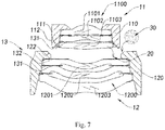
- the first lens module 11 comprises a first lens barrel 110 and a first lens set 1100, where the first lens set 1100 is supported by the first lens barrel 110, and the first lens barrel 110 holds the first lens set 1100 inside the first lens barrel 110.
- the second lens module 12 comprises a second lens barrel 120 and a second lens set 1200, where the second lens set 1200 is supported by the second lens barrel 120, and the second lens barrel 120 holds the second lens set 1200 inside the second lens barrel 120.
- the first lens set 1100 of the first lens module 11 comprises three lenses, defined from the object side to the image side as a first lens 1101, a second lens 1102 and a third lens 1103, and the second lens set 1200 of the second lens module 12 comprises three lenses, defined from the object side to the image side as a fourth lens 1201, a fifth lens 1202 and a sixth lens 1203.
- the number of lenses included in the first lens set 1100 and the number of lenses included in the second lens set 1200 are not limited to three. According to different optical designs and requirements, the number of lenses in the first lens set 1100 and the number of lenses in the second lens set 1200 may be changed correspondingly.
- the lens assembly 10 further comprises at least one spacer 13, and the spacer 13 are disposed between the lenses, so that the lenses of the first lens set 1100 and the second lens set 1200 have an identical clear aperture.
- the spacer 13 is a spacer ring 131, and the spacer ring 131 is disposed between two lenses, to ensure a certain aperture for light.
- the spacer 13 is a coating 132, the coating 132 is a light-blocking material, and the coating 132 is coated on one or two surfaces of an edge of the lens. The spacer 13 blocks the unnecessary light-transmissive edge portion of the lens.
- a lens nearest to the image side in the first lens module 11 and a lens nearest to the object side in the second lens module 12 are not in contact with each other, and do not press against each other through the spacer 13.
- the spacing 20 is located between the edge of the third lens 1103 in the first lens set 1100 and the edge of the fourth lens 1104 in the second lens set 1200.
- the spacing 20 is a non-light-transmissive portion between the third lens 1103 and the fourth lens 1104, and is formed due to the reason that the first lens set 1100 and the second lens set 1200 are connected and assembled to each other by means of the first lens barrel 110 and the second lens barrel 120 because the first lens set 1100 is supported by the first lens barrel 110 and the second lens set 1200 is supported by the second lens barrel 120.
- the first lens set 1100 and the second lens set 1200 are adjusted by means of the spacing 20, to compensate for losses such as peaks, field curvature, and an image plane inclination caused by the assembly tolerance.
- the spacing 20 is located only between the third lens 1103 and the fourth lens 1201, and lenses in each lens set are in contact with and press against each other. That is, the first lens 1101 and the second lens 1102 are in contact with and press against each other, the second lens 1102 and the third lens 1103 are in contact with and press against each other, the fourth lens 1201 and the fifth lens 1202 are in contact with and press against each other, and the fifth lens 1202 and the sixth lens 1203 are in contact with and press against each other.
- first lens 1101 and the second lens 1102, the second lens 1102 and the third lens 1103, the fourth lens 1201 and the fifth lens 1202, and the fifth lens 1202 and the sixth lens 1203 may be in contact with and press against each other by means of the spacer 13.
- the spacing 20 between the third lens 1103 and the fourth lens 1201 has certain impact on the assembly of the entire split lens assembly 10 into the camera module.
- the first lens set 1100 and the second lens set 1200 are respectively mounted in the first lens barrel 110 and the second lens barrel 120, the calibration of the first lens module 11 and the second lens module 12 has been completed in advance. That is to say, during the image quality calibration of the first lens set 1100 and the second lens set 1200, the spacing 20 makes the calibration of the image quality of the two lens sets easier.
- image quality compensation is performed for the first lens set 1100, the second lens set 1200 and the photosensitive device, and there is no accumulative error.
- the first lens module 11 and the second lens module 12 in the split lens assembly 10 are connected to each other by means of the first lens barrel 110 and the second lens barrel 120, so that the first lens set 1100 and the second lens set 1200 can be assembled and image quality compensation can be performed.
- the first lens barrel 110 comprises a first mounting portion 112
- the second lens assembly 120 comprises a second mounting portion 122
- the first mounting portion 112 can be assembled to the second mounting portion 122, so as to assemble the first lens barrel 110 to the second lens barrel 120.
- the first lens module 11 and the second lens module 12 are respectively assembled as a lens module, then connected to each other by means of the first lens barrel 110 and the second lens barrel 120, and packaged with the connecting medium 30.
- the connecting medium 30 comprises a mounting medium 32, and the mounting medium 32 is used for fixing the first mounting portion 112 of the first lens barrel 110 to the second mounting portion 122 of the second lens barrel 120.
- the first lens barrel 110 further comprises a fixed portion 111, and the fixed portion 111 is fixed to a lens nearest to the image side in the first lens set 1100. That is to say, the third lens 1103 is fixed to the fixed portion 111 of the first lens barrel 110.
- the connecting medium 30 further comprises a fixing medium 31, and the fixing medium 31 is used between the third lens 1103 and the fixed portion 111 of the first lens barrel 110 to fix the third lens 1103 to the fixed portion 111 of the first lens barrel 110.
- the spacing 20 provides a space for the connecting medium 30.
- the spacing 20 can provide a space for the fixing medium 31 or the mounting medium 32.
- the fixing medium 31 or the mounting medium 32 is a photocuring material.
- the function of the fixing medium 31 or the mounting medium 32 can be effectively exploited by means of the spacing 20.
- the mounting medium 32 may flow into the spacing 20 to fill the spacing to a certain extent, thereby ensuring the final firm state of the split lens assembly.
- the spacer 13 does not fill the spacing 20.
- Fig. 3 and Fig. 4 respectively illustrate a case where the spacer ring 131 is used and a case where the coating 132 is used. Because the first lens set 1100 and the second lens set 1200 are assembled to each other by means of the first lens barrel 110 and the second lens barrel 120, the spacing 20 between a lens nearest to the image side in the first lens set 1100 and a lens nearest to the object side in the second lens set 1200 will not be affected by the spacer 13. Specifically, as shown in Fig.
- the first lens 1101 and the second lens 1102 are in contact with each other and the second lens 1102 and the third lens 1102 are in contact with each other by means of the spacer ring 131.
- the first lens set 1100 is mounted to the first lens barrel 110 in an order of the first lens 1101, the spacer ring 131, the second lens 1102, the spacer ring 131, and the third lens 1103. In this way, the lenses and the spacer rings 131 press against each other, so that the lenses can be stably mounted.
- the second lens set 1200 is mounted to the second lens barrel 120 in an order of the spacer ring 131, the fourth lens 1201, the spacer ring 131, the fifth lens 1202, the spacer ring 131, and the sixth lens 1203. Therefore, the first lens 1101 and the second lens 1102, the second lens 1102 and the third lens 1103, the fourth lens 1201 and the fifth lens 1202, and the fifth lens 1202 and the sixth lens 1203 are in contact with and fixed to each other by means of the spacer ring 131.
- the third lens 1103 and the fourth lens 1201 are separated by the spacer ring 131, the spacing 20 is located between the third lens 1103 and this spacer ring 131.
- the coating 132 is used, as shown in Fig.
- the situation of the spacing 20 is similar.
- the spacing 20 is located between the third lens 1103 and this coating 132.
- the thickness of the coating 132 is negligible compared with the thickness of the lens, and therefore the height of the spacing 20 may be construed as the smallest distance between the edges of the third lens 1103 and the fourth lens 1201.
- the spacing 20 may be of an uneven shape, and its width may change continuously or discontinuously, but the spacing 20 has a minimum height.
- the minimum height of the spacing 20 is defined here.
- the minimum height of the spacing 20 refers to the smallest height between non-light-transmissive portions of an image side surface of a lens or spacer nearest to the image side in the first lens set 1100 and an object side surface of a lens or spacer nearest to the object side in the second lens set 1200. That is to say, in this embodiment, when no spacer 13 is located between the third lens 1103 and the fourth lens 1201, the minimum height of the spacing 20 is the smallest distance between non-light-transmissive portions of the third lens 1103 and the fourth lens 1201.
- the minimum height of the spacing 20 is the smallest distance between non-light-transmissive portions of the image side surface of the spacer 13 on the image side of the third lens 1103 and the object side surface of the spacer 13 on the object side of the fourth lens 1201.
- the minimum height of the spacing 20 is the smallest distance between non-light-transmissive portions of the spacer 13 on the image side of the third lens 1103 and the object side surface of the fourth lens 1201.
- the minimum height of the spacing 20 is the smallest distance between non-light-transmissive portions of the image side surface of the third lens 1103 and the spacer 13 on the object side of the fourth lens 1201.
- the rest can be deduced by analogy, and will not be enumerated herein.
- the range of the minimum height of the spacing 20 should be selected properly.
- the minimum height of the spacing 20 ranges preferably greater than or equal to 0.02 mm. More preferably, the minimum height of the spacing 20 ranges from 0.15 mm to 1 mm (including 0.15 mm and 1 mm) . Still further, the minimum height of the spacing 20 ranges from 0.15 mm to 0.7 mm (including 0.15 mm and 0.7 mm).
- the split lens assembly 10 is assembled into a camera module.
- the split lens assembly 10 comprises a first lens module 11 and a second lens module 12.
- the first lens module 11 is assembled to the second lens module 12 by means of a connecting medium 30, so that the split lens assembly 10 has a split assembly structure, and is suitable for automatic calibration to compensate for the image quality, thereby achieving better performance.
- a certain spacing 20 is located between the first lens module 11 and the second lens module 12.
- the split lens assembly 10 has more stable image quality.
- the minimum height of the spacing 20 in this preferred embodiment is the smallest distance between non-light-transmissive portions of the spacer 13 on the image side of the third lens 1103 and the object side surface of the fourth lens 1201, as indicated by position A in Fig. 6 .
- the spacing 20 formed due to the shape is located in the non-light-transmissive area.
- the spacing 20 has different heights at position A, position B and position C.
- the height at position A is the smallest height of the spacing 20, that is, the height at position A corresponds to the minimum height of the spacing 20.
- the height of the spacing 20 at position A ranges from 0.15 mm to 0.7 mm, preferably is 0.22 mm.
- the first lens module 11 comprises a first lens barrel 110 and a first lens set 1100, where the first lens set 1100 is supported by the first lens barrel 110, and the first lens barrel 110 holds the first lens set 1100 inside the first lens barrel 110.
- the first lens set 1100 of the first lens module 11 comprises three lenses, defined from the object side to the image side as a first lens 1101, a second lens 1102 and a third lens 1103, and the second lens set 1200 of the second lens module 12 comprises three lenses, defined from the object side to the image side as a fourth lens 1201, a fifth lens 1202 and a sixth lens 1203.
- the lens assembly 10 further comprises at least one spacer 13, the spacers 13 are disposed between the lenses, so that the lenses of the first lens set 1100 and the second lens set 1200 have an identical clear aperture.
- the spacer ring 131 is located between the first lens 1101 and the second lens 1102, between the second lens 1102 and the third lens 1103, between the fourth lens 1201 and the fifth lens 1202, and between the fifth lens 1202 and the sixth lens 1203.
- the image side non-light-transmissive portion of the fourth lens 1201 is coated with the coating 132. In this way, flatness can be ensured when the fourth lens 1201 is mounted to the second lens barrel 120, thereby preventing an inclination. That is to say, the first lens 1101 and the second lens 1102, the second lens 1102 and the third lens 1103, the fourth lens 1201 and the fifth lens 1202, and the fifth lens 1202 and the sixth lens 1203 may be in contact with and press against each other by means of the spacer 13.
- the connecting medium 30 further comprises a fixing medium 31, the fixing medium 31 is used for fixing the third lens 1103 to the first lens barrel 110.
- the connecting medium 30 comprises a mounting medium 32, and the mounting medium 32 is used for fixing the first lens barrel 110 to the second lens barrel 120.
- the first lens barrel 110 further comprises a fixed portion 111, and the fixed portion 111 is fixed to a lens nearest to the image side in the first lens set 1100. That is to say, the third lens 1103 is fixed to the fixed portion 111 of the first lens barrel 110. More preferably, the fixed portion 111 is located on an inner side of an image side barrel opening of the first lens barrel 110.
- the fixing medium 31 connects and fixes the third lens 1103 to the first lens barrel 110.
- the fixing medium 31 stably connects and fixes the third lens 1103 to the first lens barrel 110 after the image quality calibration of the first lens set 1100.
- the first lens barrel 110 comprises a first mounting portion 112
- the second lens assembly 120 comprises a second mounting portion 122
- the first mounting portion 112 can be assembled to the second mounting portion 122, so as to assemble the first lens barrel 110 to the second lens barrel 120.
- the first mounting portion 112 is located on an outer surface of the first lens barrel 110
- the second mounting portion 122 is located on the top end of the second lens barrel 120, so that the mounting medium 32 can be placed between the first mounting portion 112 and the second mounting portion 122 .
- the spacing 20 can ensure the distance between the first lens set 1100 and the second lens set 1200, thereby avoiding a collision during the calibration process.
- the first lens set 1100 is assembled to the second lens set 1200.
- the first lens set 1100 is assembled to the image side of the second lens set 1200 by means of the spacing 20.
- the image quality calibration of the lenses can be completed by using an automatic calibration technology.
- the first lens barrel 110 is connected and fixed to the second lens barrel 120 by means of the mounting medium 32.
- one more lens module may be assembled to the first lens module 11 and the second lens module 12 according to design requirements. That is to say, the calibration and assembly of three lens modules are completed by means of two spacing 20. As can be deduced by analogy, assembling more lens modules is possible.
- FIG. 8 and Fig. 9 Another embodiment of the present disclosure is as shown in Fig. 8 and Fig. 9 , where the split lens assembly 10 comprises a first lens module 11 and a second lens module 12.
- the structure of the first lens module 11 and the second lens module 12 is similar to that of the split lens assembly 10 in the above-mentioned preferred embodiment, and will not be repeatedly described here.
- the first lens barrel 110 further comprises a fixed portion 111, and the fixed portion 111 is fixed to a lens nearest to the image side in the first lens set 1100. That is to say, the third lens 1103 is fixed to the fixed portion 111 of the first lens barrel 110. More preferably, the fixed portion 111 is located on an outer side of an image side barrel opening of the first lens barrel 110.
- the fixing medium 31 connects and fixes the object side surface of the third lens 1103 to the first lens barrel 110.
- the fixing medium 31 stably connects and fixes the third lens 1103 to the first lens barrel 110 after the image quality calibration of the first lens set 1100.
- the first lens barrel 110 comprises a first mounting portion 112
- the second lens assembly 120 comprises a second mounting portion 122
- the first mounting portion 112 can be assembled to the second mounting portion 122, so as to assemble the first lens barrel 110 to the second lens barrel 120.
- the first mounting portion 112 is located above the fixed portion 111 of the first lens barrel 110
- the second mounting portion 122 is located on the top end of the second lens barrel 120, so that the mounting medium 32 can be placed between the first mounting portion 112 and the second mounting portion 122. As shown in Fig.
- the spacing 20 can ensure the distance between the first lens set 1100 and the second lens set 1200, thereby avoiding a collision during the calibration process.
- the first lens set 1100 and the second lens set 1200 are respectively mounted in the first lens barrel 110 and the second lens barrel 120, the calibration of the first lens module 11 and the second lens module 12 has been completed in advance. That is to say, during the image quality calibration of the first lens set 1100 and the second lens set 1200, the spacing 20 makes the calibration of the image quality of the two lens sets easier.
- the minimum height of the spacing 20 in this preferred embodiment is the smallest distance between non-light-transmissive portions of the spacer 13 on the image side of the third lens 1103 and the object side surface of the fourth lens 1201, as indicated by position A in Fig. 9 .
- the spacing 20 formed due to the shape is located in the non-light-transmissive area.
- the spacing 20 has different heights at position A, position B and position C.
- the height at position A is the smallest height of the spacing 20, that is, the height at position A corresponds to the minimum height of the spacing 20.
- the height of the spacing 20 at position A ranges from 0.15 mm to 0.7 mm, preferably is 0.34 mm.
- FIG. 10 and Fig. 11 Another embodiment of the present disclosure is as shown in Fig. 10 and Fig. 11 , where the split lens assembly 10 comprises a first lens module 11 and a second lens module 12.
- the structure of the first lens module 11 and the second lens module 12 is similar to that of the split lens assembly 10 in the above-mentioned preferred embodiment, and will not be repeatedly described here.
- the first lens barrel 110 further comprises a fixed portion 111, and the fixed portion 111 is fixed to a lens nearest to the image side in the first lens set 1100. That is to say, the third lens 1103 is fixed to the fixed portion 111 of the first lens barrel 110. More preferably, the fixed portion 111 is located on an inner side of an image side barrel opening of the first lens barrel 110.
- the fixing medium 31 connects and fixes the object side surface of the third lens 1103 to the first lens barrel 110.
- the fixing medium 31 stably connects and fixes the third lens 1103 to the first lens barrel 110 after the image quality calibration of the first lens set 1100.
- the first lens barrel 110 comprises a first mounting portion 112
- the second lens assembly 120 comprises a second mounting portion 122
- the first mounting portion 112 can be assembled to the second mounting portion 122, so as to assemble the first lens barrel 110 to the second lens barrel 120.
- the first mounting portion 112 is located on an outer edge of the first lens barrel 110
- the second mounting portion 122 is located on the top end of the second lens barrel 120, so that the mounting medium 32 can be placed between the first mounting portion 112 and the second mounting portion 122. As shown in Fig.
- the spacing 20 can ensure the distance between the first lens set 1100 and the second lens set 1200, thereby avoiding a collision during the calibration process.
- the first lens set 1100 and the second lens set 1200 are respectively mounted in the first lens barrel 110 and the second lens barrel 120, the calibration of the first lens module 11 and the second lens module 12 has been completed in advance. That is to say, during the image quality calibration of the first lens set 1100 and the second lens set 1200, the spacing 20 makes the calibration of the image quality of the two lens sets easier.
- image quality compensation is performed for the first lens set 1100, the second lens set 1200 and the photosensitive device, to compensate for losses such as peaks, field curvature, and an image plane inclination caused by the assembly tolerance, and there is no accumulative error.
- the split lens assembly 10 is assembled into a camera module.
- the split lens assembly 10 comprises a first lens module 11 and a second lens module 12.
- the first lens module 11 is assembled to the second lens module 12 by means of a connecting medium 30, so that the split lens assembly 10 has a split assembly structure, and is suitable for automatic calibration to compensate for the image quality, thereby achieving better performance.
- a certain spacing 20 is located between the first lens module 11 and the second lens module 12. Because the first lens module 11 and the second lens module 12 in the split lens assembly 10 do not rely on the structural pressing and support of the lenses, which is different from conventional assembly methods, the split lens assembly 10 has more stable image quality.
- the first lens module 11 comprises a first lens barrel 110 and a first lens set 1100, where the first lens set 1100 is supported by the first lens barrel 110, and the first lens barrel 110 holds the first lens set 1100 inside the first lens barrel 110.
- the second lens module 12 comprises a second lens barrel 120 and a second lens set 1200, where the second lens set 1200 is supported by the second lens barrel 120, and the second lens barrel 120 holds the second lens set 1200 inside the second lens barrel 120.
- the first lens set 1100 of the first lens module 11 comprises three lenses, defined from the object side to the image side as a first lens 1101, a second lens 1102 and a third lens 1103, and the second lens set 1200 of the second lens module 12 comprises three lenses, defined from the object side to the image side as a fourth lens 1201, a fifth lens 1202 and a sixth lens 1203.
- the lens assembly 10 further comprises at least one spacer 13, the spacers 13 are disposed between the lenses, so that the lenses of the first lens set 1100 and the second lens set 1200 have an identical clear aperture.
- a compression ring 133 is disposed on the image side of the third lens 1103.
- the compression ring 133 is adapted to fix the third lens 1103 inside the first lens barrel 110.
- the compression ring 133 can block stray light.
- the spacing 20 is the distance between the object side of the third lens 1103 and the image side of the fourth lens 1201.
- the minimum height of the spacing 20 is preferably 0.34 mm.
- the spacer ring 131 is located between the first lens 1101 and the second lens 1102, between the second lens 1102 and the third lens 1103, between the fourth lens 1201 and the fifth lens 1202, and between the fifth lens 1202 and the sixth lens 1203.
- the spacer ring 131 is also disposed on the image side of the fourth lens 1201. That is to say, the first lens 1101 and the second lens 1102, the second lens 1102 and the third lens 1103, the fourth lens 1201 and the fifth lens 1202, and the fifth lens 1202 and the sixth lens 1203 may be in contact with and press against each other by means of the spacer 13.
- the connecting medium 30 further comprises a fixing medium 31, the fixing medium 31 is used for the third lens 1103 and the compression ring 133 to fix the third lens 1103 to the first lens barrel 110.
- the connecting medium 30 comprises a mounting medium 32, and the mounting medium 32 is used for fixing the first lens barrel 110 and the second lens barrel 120, to ensure the final firm state of the lens assembly or the camera module.
- the spacing 20 can ensure the distance between the first lens set 1100 and the second lens set 1200, thereby avoiding a collision during the calibration process.
- the first lens set 1100 and the second lens set 1200 are respectively mounted in the first lens barrel 110 and the second lens barrel 120, the calibration of the first lens module 11 and the second lens module 12 has been completed in advance. That is to say, during the image quality calibration of the first lens set 1100 and the second lens set 1200, the spacing 20 makes the calibration of the image quality of the two lens sets easier.
- image quality compensation is performed for the first lens set 1100, the second lens set 1200 and the photosensitive device, to compensate for losses such as peaks, field curvature, and an image plane inclination caused by the assembly tolerance, and there is no accumulative error.
Landscapes
- Physics & Mathematics (AREA)
- General Physics & Mathematics (AREA)
- Optics & Photonics (AREA)
- Lens Barrels (AREA)
- Blocking Light For Cameras (AREA)
- Structure And Mechanism Of Cameras (AREA)
- Lenses (AREA)
Abstract
Description
- The present disclosure relates to a split lens assembly and a camera module, and particularly to a lens assembly applicable to a camera module in a smart mobile device.
- The quality of the lens assembly is a key factor that directly influences the camera performance. A high-quality lens assembly is of great importance to the production of high-quality products in the video camera industry. In the camera and video camera area, research on various aspects of the lens assembly can reflect a manufacturer's pursuit of high quality and high performance. The popularity of smart mobile devices provides a broad market for optical lenses and also poses many challenges for the design, research and development of optical lenses in the smart mobile devices.
- Smart mobile devices, especially mobile phones, tablet computers, portable computers, smart service terminals, or even portable identification devices, are popular products on the market. Camera modules have been directly assembled in the device as a vital sensor device. For many devices, the requirements on the camera modules are no less than those on the professional camera equipment. Higher requirements are also imposed on the lens assembly in the camera module.
- Clearly, the most effective method is to improve the lens assembly in the camera module, because the key component affecting the resolution of the camera module is the lens assembly. A conventional lens assembly is obtained by mounting several lenses into a black lens barrel, and fixing the lenses in the lens barrel. For conventional lens assemblies, for example, large aperture lens assemblies, due to the machining tolerance of the lens and the lens barrel, in the case of a high sensitivity optical system and a given resolution specification, conventional production methods may cause a great loss in yield, resulting in high production costs and low output.
- Particularly, in conventional lens assemblies and camera modules, all lenses are in contact with and press against each other. The edges of the lenses are fixed in a stacked fashion. Conventionally, a spacer ring is generally used to block non-light-transmissive portions of lenses, as a result, the lenses are placed in contact with and pressing against the spacer ring. Furthermore, to ensure the quality of the lens assembly, the single component tolerance and assembly precision need to be strictly controlled, and the lenses need to be rotated for particular eccentric compensation during the assembly process.
- How to improve the performance of the lens assembly in the camera module while increasing the yield and the production efficiency as well as reducing the cost is an important research topic for the production of camera modules.
- An objective of the present disclosure is to provide a split lens assembly and a camera module, which use a combination of two lens modules, to improve the performance of the lens assembly while reducing the design costs, assembly difficulty and production costs.
- Another objective of the present disclosure is to provide a split lens assembly and a camera module, which, by simplifying the structure of the lens module and by means of automatic calibration, make the split lens assembly to have higher performance when applied to the camera module.
- Another objective of the present disclosure is to provide a split lens assembly and a camera module, which, by simplifying the design and mounting of at least one lens in the lens module, make the entire split lens assembly have good integrity and consistency, thereby facilitating the image quality calibration.
- An objective of the present disclosure is to provide a split lens assembly and a camera module, where the relative positions of lens sets of different lens modules are adjusted by adjusting the relative positions of the lens modules, to compensate for losses such as peaks, field curvature, and an image plane inclination caused by lenses and assembly tolerances, thereby improving the overall image quality of the entire camera module.
- Another objective of the present disclosure is to provide a split lens assembly and a camera module, the lens module further comprises a lens barrel. The lens barrel has a mounting portion suitable for different connection manners, so that two lens modules can be assembled together stably and reliably.
- Another objective of the present disclosure is to provide a split lens assembly and a camera module, where the mounting portions are reliably connected by means of a connecting medium, thereby ensuring the final firm state of the lens assembly or the camera module.
- Another objective of the present disclosure is to provide a split lens assembly and a camera module, where the mounting portion is suitable for multiple connection manners. For different lens assemblies, the connection manner of the mounting portion is adaptive.
- Another objective of the present disclosure is to provide a split lens assembly and a camera module, the split lens assembly further comprises at least one spacer, and the spacer is disposed between the lenses for mechanical restriction or light blocking, so as to ensure the quality of the lens module.
- Another objective of the present disclosure is to provide a split lens assembly and a camera module, where the spacer is flexibly designed to ensure reasonableness and meet the requirements of the lens module, so as to ensure the quality of the camera module.
- Another objective of the present disclosure is to provide a split lens assembly and a camera module, where a certain spacing is located between a lens set of one lens module and a lens set of another lens module, and the lens sets are not in contact with or press against each other by means of the spacer.
- Another objective of the present disclosure is to provide a split lens assembly and a camera module. For the requirements of different lenses on the image quality, the cooperation between the spacer and the mounting portion makes the optical relationship between two lens modules stable and reliable.
- Another objective of the present disclosure is to provide a split lens assembly and a camera module, where the lenses are closely arranged in an orderly manner by means of the spacer, thereby improving the integrity of the split lens assembly.
- Another objective of the present disclosure is to provide a split lens assembly and a camera module, where the spacer is wholly or partially a light blocking coating, thereby simplifying the mounting of the lenses in the lens module.
- Another objective of the present disclosure is to provide a split lens assembly and a camera module, where the lens module is fixed by means of the connecting medium, thereby ensuring stable packaging and effectively avoiding stray light.
- Another objective of the present disclosure is to provide a split lens assembly and a camera module, where the packaging of the connecting medium does not affect the spacing, and automatic calibration can be achieved while ensuring the optical stability, thereby reducing the production difficulty of the lens assembly and the camera module.
- According to an aspect of the present disclosure, the present disclosure provides a split lens assembly, comprising at least two lens modules and having a spacing provided between every two lens modules, each of the lens modules further comprising a lens set and a lens barrel, the lens barrel holding the lens set inside the lens barrel, the lens set comprising at least two lenses, and the spacing being provided between an edge of a lens near an image side of a first lens set and an edge of a lens near an object side of a second lens set.
- According to an aspect of the present disclosure, the present disclosure provides a split lens assembly, comprising:
- a first lens module comprising a first lens set; and
- a second lens module comprising a second lens set, the first lens module being assembled to the second lens module, and a spacing for calibrating and assembling the first lens module and the second lens module being located between the first lens set and the second lens set.
- According to an embodiment of the present disclosure, the split lens assembly further comprises a connecting medium, and the first lens module is fixed to the second lens module by means of the connecting medium.
- According to an embodiment of the present disclosure, the first lens module further comprises a first lens set and a first lens barrel, wherein the first lens set is supported by the first lens barrel, and the first lens barrel holds the first lens set inside the first lens barrel; and the second lens module further comprises a second lens barrel and a second lens set, wherein the second lens set is supported by the second lens barrel, and the second lens barrel holds the second lens set inside the second lens barrel.
- According to an embodiment of the present disclosure, the first lens barrel is connected and fixed to the second lens barrel by means of the connecting medium.
- According to an embodiment of the present disclosure, the spacing is located between an image side of the first lens set and an object side of the second lens set.
- According to an embodiment of the present disclosure, the first lens set comprises at least two lenses, the second lens set comprises at least two lenses.
- According to an embodiment of the present disclosure, image quality calibration is performed for the first lens set and the second lens set respectively, and then image quality calibration is performed for the first lens set and the second lens set.
- According to an embodiment of the present disclosure, the connecting medium is a thermosetting material.
- According to an embodiment of the present disclosure, the connecting medium is a photocuring material.
- According to an embodiment of the present disclosure, the spacing is located between non-light-transmissive portions of an image side surface of a lens nearest to the image side in the first lens set and an object side surface of a lens nearest to the object side in the second lens set.
- According to an embodiment of the present disclosure, the split lens assembly further comprises at least one spacer, and the spacer is disposed between the lenses, so that the lenses of the first lens set and the second lens set have an identical clear aperture.
- According to an embodiment of the present disclosure, the spacing is located between non-light-transmissive portions of an image side surface of a spacer nearest to the image side in the first lens set and an object side surface of a lens nearest to the object side in the second lens set.
- According to an embodiment of the present disclosure, the spacing is located between non-light-transmissive portions of an image side surface of a lens nearest to the image side in the first lens set and an object side surface of a spacer nearest to the object side in the second lens set.
- According to an embodiment of the present disclosure, the spacer is a spacer ring.
- According to an embodiment of the present disclosure, the spacer is a coating, the coating is a light-blocking material, and the coating is coated on an edge of at least one surface of the lens.
- According to an embodiment of the present disclosure, a minimum height of the spacing ranges greater than or equal to 0.02 mm.
- According to an embodiment of the present disclosure, a minimum height of the spacing ranges from 0.15 mm to 1 mm.
- According to another aspect of the present disclosure, the present disclosure provides a camera module, formed by assembling the split lens assembly and a photosensitive device disposed corresponding to the split lens assembly and performing image quality calibration.
- According to another aspect of the present disclosure, the present disclosure provides a split lens assembly, comprising:
at least two lens modules, each lens module comprising a lens set, a lens module being assembled to another lens module, and a spacing being located between non-light-transmissive portions of every two neighboring lens sets for facilitating the automatic calibration of the lens modules to compensate for image quality. - According to an embodiment of the present disclosure, a minimum height of the spacing ranges greater than or equal to 0.02 mm.
- According to an embodiment of the present disclosure, a minimum height of the spacing ranges from 0.15 mm to 1 mm.
-
-
Fig. 1 is a schematic structural diagram of a split lens assembly according to a preferred embodiment of the present disclosure; -
Fig. 2 is a schematic structural diagram of a lens module in the split lens assembly according to the above-mentioned preferred embodiment of the present disclosure; -
Fig. 3 is a schematic structural diagram of a lens module with a spacer ring in the split lens assembly according to the above-mentioned preferred embodiment of the present disclosure; -
Fig. 4 is a schematic structural diagram of a lens module with a coating in the split lens assembly according to the above-mentioned preferred embodiment of the present disclosure; -
Fig. 5 is a schematic structural diagram of a lens module in a split lens assembly according to a preferred embodiment of the present disclosure; -
Fig. 6 is a detailed structural diagram of lens modules in the split lens assembly according to the above-mentioned preferred embodiment of the present disclosure and a camera module; -
Fig. 7 is a schematic diagram of assembling of the split lens assembly according to the above-mentioned preferred embodiment of the present disclosure and a camera module; -
Fig. 8 is a schematic structural diagram of a lens module in a split lens assembly according to a preferred embodiment of the present disclosure; -
Fig. 9 is a detailed structural diagram of lens modules in the split lens assembly according to the above-mentioned preferred embodiment of the present disclosure; -
Fig. 10 is a schematic structural diagram of a lens module in a split lens assembly according to a preferred embodiment of the present disclosure; -
Fig. 11 is a detailed structural diagram of lens modules in the split lens assembly according to the above-mentioned preferred embodiment of the present disclosure; -
Fig. 12 is a schematic structural diagram of a lens module in a split lens assembly according to a preferred embodiment of the present disclosure; and -
Fig. 13 is a detailed structural diagram of the lens modules in the split lens assembly according to the above-mentioned preferred embodiment of the present disclosure. - The following description is used for disclosing the present disclosure to enable those skilled in the art to implement the present disclosure. In the following description, preferred embodiments are provided by way of example only, and those skilled in the art may easily conceive of other variations. The basic principle of the present disclosure defined in the following description applies to other implementation solutions, variant solutions, improved solutions, equivalent solutions and other technical solutions that do not depart from the spirit and scope of the present disclosure.
- It should be understood by those skilled in the art that in the disclosure of the present disclosure, the positions and positional relationships indicated by the terms such as "longitudinal", "transversal", "up", "down", " front", "rear", "left", "right", "vertical", "horizontal", "top", "bottom", "inside", "outside" are based on the positions or positional relationships shown in the accompany drawings, which are used only for convenient and brief description, and do not indicate or imply that the indicated apparatus or element must be in a specific position, and must be constructed and operated in a specific position. Therefore, the above-mentioned terms should not be considered as a limitation on the present disclosure.
- It may be understood that the terms "a" and "an" should be construed as "at least one" or "one or more". That is, the term "a portion" means that the number of portions may be one in an embodiment, and may be plural in another embodiment.
- The present disclosure provides a split lens assembly and a camera module. The split lens assembly and the camera module using the split lens assembly are assembled in a smart device for image capturing. The first preferred embodiment of the present disclosure is illustrated with reference to
Fig. 1 to Fig. 4 . Thesplit lens assembly 10 comprises afirst lens module 11 and asecond lens module 12. Thefirst lens module 11 is assembled to thesecond lens module 12 by means of a connectingmedium 30, so that thesplit lens assembly 10 has a split assembly structure, and is suitable for automatic calibration to compensate for the image quality, thereby achieving better performance. It should be noted that in order to illustrate and explain the structure of this preferred embodiment, an image end of thefirst lens module 11 is assembled to an object end of thesecond lens module 12. Therefore, in thesplit lens assembly 10, thefirst lens module 11 is an object end lens module, and thesecond lens module 12 is an image end lens module. Further, an image end of thesecond lens module 12 is assembled to a camera module so that thesplit lens assembly 10 is assembled into a camera module. That is to say, in this preferred embodiment, thesplit lens assembly 10 is formed by respectively assembling thefirst lens module 11 and thesecond lens module 12 as a lens module followed by packaging with the connectingmedium 30. That is to say, thefirst lens module 11 is assembled and the image quality of thefirst lens module 11 is adjusted to ensure good image quality and structural integrity and firmness of thefirst lens module 11, and thesecond lens module 12 is assembled and the image quality of thesecond lens module 12 is adjusted to ensure good image quality and structural integrity and firmness of thesecond lens module 12. Then, thefirst lens module 11 and thesecond lens module 12 are assembled into thesplit lens assembly 10. Compared with a conventional lens assembly, thesplit lens assembly 10 can avoid the accumulated tolerance during assembly and also facilitate image quality calibration. Specifically, while ensuring the structural stability of thefirst lens module 11 and thesecond lens module 12, the performance of thesplit lens assembly 10 can be improved. During assembly of thefirst lens module 11 and thesecond lens module 12, the tolerance and image quality consistency are adjusted, thereby greatly reducing the production difficulty and effectively increasing the yield. The single component tolerance and assembly precision that need to be strictly controlled can be ensured. In addition, when thesplit lens assembly 10 is assembled into the camera module, the good image quality of thesplit lens assembly 10 also makes it easier to adjust the image quality, so that thesplit lens assembly 10 can be assembled into a camera module in different manners. For example, when thesplit lens assembly 10 needs to be performed image quality compensation with a photosensitive chip, the good image quality of thesplit lens assembly 10 makes it easier to perform the adjustment with the photosensitive chip, so that the deviation of the image quality compensation of thesplit lens assembly 10 and the photosensitive chip is easily controlled within a predetermined range. Whereby, the light performance and the production yield of the camera module using thesplit lens assembly 10 can be effectively improved. It should be noted that as shown inFig. 1 , after thefirst lens module 11 and thesecond lens module 12 are assembled, acertain spacing 20 is located between thefirst lens module 11 and thesecond lens module 12. It should be noted that thespacing 20 is not a spacing formed due to the shape of the lenses, but is located between edges of the lenses in thefirst lens module 11 and thesecond lens module 12, so that the edges of the lenses in thefirst lens module 11 are not in contact with and do not press against the edges of the lenses in thesecond lens module 12. That is to say, there is no structural contact between the lenses in thefirst lens module 11 and the lenses in thesecond lens module 12 in thesplit lens assembly 10, thereby ensuring that the structures of the lenses in thefirst lens module 11 and the lenses in thesecond lens module 12 are not affected. In addition, particular eccentric compensation is performed for the lenses in the lens modules during the assembly process, thereby ensuring the stable image quality of thefirst lens module 11 and thesecond lens module 12 after assembly. - Because the
first lens module 11 and thesecond lens module 12 in thesplit lens assembly 10 do not rely on the structural pressing and support of the lenses, which is different from conventional assembly methods, thesplit lens assembly 10 has more stable image quality. As shown inFig. 2 , in particular, thefirst lens module 11 comprises afirst lens barrel 110 and afirst lens set 1100, where thefirst lens set 1100 is supported by thefirst lens barrel 110, and thefirst lens barrel 110 holds the first lens set 1100 inside thefirst lens barrel 110. Similarly, thesecond lens module 12 comprises asecond lens barrel 120 and asecond lens set 1200, where thesecond lens set 1200 is supported by thesecond lens barrel 120, and thesecond lens barrel 120 holds the second lens set 1200 inside thesecond lens barrel 120. In order to explain and illustrate thefirst lens module 11 and thesecond lens module 12 in thesplit lens assembly 10, The first lens set 1100 of thefirst lens module 11 comprises three lenses, defined from the object side to the image side as afirst lens 1101, asecond lens 1102 and athird lens 1103, and the second lens set 1200 of thesecond lens module 12 comprises three lenses, defined from the object side to the image side as afourth lens 1201, afifth lens 1202 and asixth lens 1203. Definitely, the number of lenses included in thefirst lens set 1100 and the number of lenses included in thesecond lens set 1200 are not limited to three. According to different optical designs and requirements, the number of lenses in thefirst lens set 1100 and the number of lenses in thesecond lens set 1200 may be changed correspondingly. Although the number of lenses in thefirst lens set 1100 and the number of lenses in thesecond lens set 1200 are not limited to the combination of 3 + 3, it is possible that this combination is an appropriate implementation. In addition, thelens assembly 10 further comprises at least onespacer 13, and thespacer 13 are disposed between the lenses, so that the lenses of thefirst lens set 1100 and the second lens set 1200 have an identical clear aperture. Preferably, thespacer 13 is aspacer ring 131, and thespacer ring 131 is disposed between two lenses, to ensure a certain aperture for light. Preferably, thespacer 13 is acoating 132, thecoating 132 is a light-blocking material, and thecoating 132 is coated on one or two surfaces of an edge of the lens. Thespacer 13 blocks the unnecessary light-transmissive edge portion of the lens. - It should be noted that a lens nearest to the image side in the
first lens module 11 and a lens nearest to the object side in thesecond lens module 12 are not in contact with each other, and do not press against each other through thespacer 13. Specifically, the spacing 20 is located between the edge of thethird lens 1103 in thefirst lens set 1100 and the edge of the fourth lens 1104 in thesecond lens set 1200. The spacing 20 is a non-light-transmissive portion between thethird lens 1103 and the fourth lens 1104, and is formed due to the reason that thefirst lens set 1100 and thesecond lens set 1200 are connected and assembled to each other by means of thefirst lens barrel 110 and thesecond lens barrel 120 because thefirst lens set 1100 is supported by thefirst lens barrel 110 and thesecond lens set 1200 is supported by thesecond lens barrel 120. In image quality calibration, thefirst lens set 1100 and thesecond lens set 1200 are adjusted by means of thespacing 20, to compensate for losses such as peaks, field curvature, and an image plane inclination caused by the assembly tolerance. - It should be noted that, the spacing 20 is located only between the
third lens 1103 and thefourth lens 1201, and lenses in each lens set are in contact with and press against each other. That is, thefirst lens 1101 and thesecond lens 1102 are in contact with and press against each other, thesecond lens 1102 and thethird lens 1103 are in contact with and press against each other, thefourth lens 1201 and thefifth lens 1202 are in contact with and press against each other, and thefifth lens 1202 and thesixth lens 1203 are in contact with and press against each other. Definitely, thefirst lens 1101 and thesecond lens 1102, thesecond lens 1102 and thethird lens 1103, thefourth lens 1201 and thefifth lens 1202, and thefifth lens 1202 and thesixth lens 1203 may be in contact with and press against each other by means of thespacer 13. - Definitely, the spacing 20 between the
third lens 1103 and thefourth lens 1201 has certain impact on the assembly of the entiresplit lens assembly 10 into the camera module. First, when thefirst lens set 1100 and thesecond lens set 1200 are respectively mounted in thefirst lens barrel 110 and thesecond lens barrel 120, the calibration of thefirst lens module 11 and thesecond lens module 12 has been completed in advance. That is to say, during the image quality calibration of thefirst lens set 1100 and thesecond lens set 1200, the spacing 20 makes the calibration of the image quality of the two lens sets easier. In addition, when assembled into the camera module, for example, when the photosensitive device is further calibrated, image quality compensation is performed for thefirst lens set 1100, thesecond lens set 1200 and the photosensitive device, and there is no accumulative error. - The
first lens module 11 and thesecond lens module 12 in thesplit lens assembly 10 are connected to each other by means of thefirst lens barrel 110 and thesecond lens barrel 120, so that thefirst lens set 1100 and the second lens set 1200 can be assembled and image quality compensation can be performed. Specifically, thefirst lens barrel 110 comprises a first mountingportion 112, thesecond lens assembly 120 comprises a second mountingportion 122, and the first mountingportion 112 can be assembled to the second mountingportion 122, so as to assemble thefirst lens barrel 110 to thesecond lens barrel 120. Thefirst lens module 11 and thesecond lens module 12 are respectively assembled as a lens module, then connected to each other by means of thefirst lens barrel 110 and thesecond lens barrel 120, and packaged with the connectingmedium 30. Specifically, the connectingmedium 30 comprises a mountingmedium 32, and the mountingmedium 32 is used for fixing the first mountingportion 112 of thefirst lens barrel 110 to the second mountingportion 122 of thesecond lens barrel 120. In addition, in this preferred embodiment, thefirst lens barrel 110 further comprises a fixedportion 111, and the fixedportion 111 is fixed to a lens nearest to the image side in thefirst lens set 1100. That is to say, thethird lens 1103 is fixed to the fixedportion 111 of thefirst lens barrel 110. Correspondingly, the connectingmedium 30 further comprises a fixingmedium 31, and the fixingmedium 31 is used between thethird lens 1103 and the fixedportion 111 of thefirst lens barrel 110 to fix thethird lens 1103 to the fixedportion 111 of thefirst lens barrel 110. It should be understood by those skilled in the art that, the spacing 20 provides a space for the connectingmedium 30. Specifically, for the fixing of thethird lens 1103 by the fixingmedium 31, and the fixing of thefirst lens barrel 110 and thesecond lens barrel 120 by the mountingmedium 32, the spacing 20 can provide a space for the fixingmedium 31 or the mountingmedium 32. For example, the fixingmedium 31 or the mountingmedium 32 is a photocuring material. The function of the fixingmedium 31 or the mountingmedium 32 can be effectively exploited by means of thespacing 20. Definitely, in some feasible implementations, the mountingmedium 32 may flow into the spacing 20 to fill the spacing to a certain extent, thereby ensuring the final firm state of the split lens assembly. - It should be noted that, the
spacer 13 does not fill thespacing 20.Fig. 3 andFig. 4 respectively illustrate a case where thespacer ring 131 is used and a case where thecoating 132 is used. Because thefirst lens set 1100 and thesecond lens set 1200 are assembled to each other by means of thefirst lens barrel 110 and thesecond lens barrel 120, the spacing 20 between a lens nearest to the image side in thefirst lens set 1100 and a lens nearest to the object side in thesecond lens set 1200 will not be affected by thespacer 13. Specifically, as shown inFig. 3 , in thefirst lens set 1100, thefirst lens 1101 and thesecond lens 1102 are in contact with each other and thesecond lens 1102 and thethird lens 1102 are in contact with each other by means of thespacer ring 131. Preferably, thefirst lens set 1100 is mounted to thefirst lens barrel 110 in an order of thefirst lens 1101, thespacer ring 131, thesecond lens 1102, thespacer ring 131, and thethird lens 1103. In this way, the lenses and the spacer rings 131 press against each other, so that the lenses can be stably mounted. Similarly, thesecond lens set 1200 is mounted to thesecond lens barrel 120 in an order of thespacer ring 131, thefourth lens 1201, thespacer ring 131, thefifth lens 1202, thespacer ring 131, and thesixth lens 1203. Therefore, thefirst lens 1101 and thesecond lens 1102, thesecond lens 1102 and thethird lens 1103, thefourth lens 1201 and thefifth lens 1202, and thefifth lens 1202 and thesixth lens 1203 are in contact with and fixed to each other by means of thespacer ring 131. Although thethird lens 1103 and thefourth lens 1201 are separated by thespacer ring 131, the spacing 20 is located between thethird lens 1103 and thisspacer ring 131. For the case where thecoating 132 is used, as shown inFig. 4 , the situation of thespacing 20 is similar. Although thethird lens 1103 and thefourth lens 1201 are separated by thecoating 132, the spacing 20 is located between thethird lens 1103 and thiscoating 132. Preferably, the thickness of thecoating 132 is negligible compared with the thickness of the lens, and therefore the height of thespacing 20 may be construed as the smallest distance between the edges of thethird lens 1103 and thefourth lens 1201. - The spacing 20 may be of an uneven shape, and its width may change continuously or discontinuously, but the
spacing 20 has a minimum height. The minimum height of thespacing 20 is defined here. The minimum height of thespacing 20 refers to the smallest height between non-light-transmissive portions of an image side surface of a lens or spacer nearest to the image side in thefirst lens set 1100 and an object side surface of a lens or spacer nearest to the object side in thesecond lens set 1200. That is to say, in this embodiment, when nospacer 13 is located between thethird lens 1103 and thefourth lens 1201, the minimum height of thespacing 20 is the smallest distance between non-light-transmissive portions of thethird lens 1103 and thefourth lens 1201. When aspacer 13 is disposed on the image side of thethird lens 1103 and aspacer 13 is disposed on the object side of thefourth lens 1201, the minimum height of thespacing 20 is the smallest distance between non-light-transmissive portions of the image side surface of thespacer 13 on the image side of thethird lens 1103 and the object side surface of thespacer 13 on the object side of thefourth lens 1201. When thespacer 13 is disposed on the image side of thethird lens 1103 and nospacer 13 is disposed on thefourth lens 1201, the minimum height of thespacing 20 is the smallest distance between non-light-transmissive portions of thespacer 13 on the image side of thethird lens 1103 and the object side surface of thefourth lens 1201. When nospacer 13 is disposed on the image side of thethird lens 1103 and thespacer 13 is disposed on the object side of thefourth lens 1201, the minimum height of thespacing 20 is the smallest distance between non-light-transmissive portions of the image side surface of thethird lens 1103 and thespacer 13 on the object side of thefourth lens 1201. The rest can be deduced by analogy, and will not be enumerated herein. The range of the minimum height of the spacing 20 should be selected properly. For example, the minimum height of the spacing 20 ranges preferably greater than or equal to 0.02 mm. More preferably, the minimum height of the spacing 20 ranges from 0.15 mm to 1 mm (including 0.15 mm and 1 mm) . Still further, the minimum height of the spacing 20 ranges from 0.15 mm to 0.7 mm (including 0.15 mm and 0.7 mm). - Another preferred embodiment of the present disclosure is as shown in
Fig. 5 to Fig. 7 . In this preferred embodiment, thesplit lens assembly 10 is assembled into a camera module. Thesplit lens assembly 10 comprises afirst lens module 11 and asecond lens module 12. Thefirst lens module 11 is assembled to thesecond lens module 12 by means of a connectingmedium 30, so that thesplit lens assembly 10 has a split assembly structure, and is suitable for automatic calibration to compensate for the image quality, thereby achieving better performance. As shown inFig. 6 , after thefirst lens module 11 and thesecond lens module 12 are assembled, acertain spacing 20 is located between thefirst lens module 11 and thesecond lens module 12. Because thefirst lens module 11 and thesecond lens module 12 in thesplit lens assembly 10 do not rely on the structural pressing and support of the lenses, which is different from conventional assembly methods, thesplit lens assembly 10 has more stable image quality. It should be noted that the minimum height of the spacing 20 in this preferred embodiment is the smallest distance between non-light-transmissive portions of thespacer 13 on the image side of thethird lens 1103 and the object side surface of thefourth lens 1201, as indicated by position A inFig. 6 . Limited by the shape of thethird lens 1103 and thefourth lens 1201, the spacing 20 formed due to the shape is located in the non-light-transmissive area. The spacing 20 has different heights at position A, position B and position C. The height at position A is the smallest height of thespacing 20, that is, the height at position A corresponds to the minimum height of thespacing 20. the height of the spacing 20 at position A ranges from 0.15 mm to 0.7 mm, preferably is 0.22 mm. - The
first lens module 11 comprises afirst lens barrel 110 and afirst lens set 1100, where thefirst lens set 1100 is supported by thefirst lens barrel 110, and thefirst lens barrel 110 holds the first lens set 1100 inside thefirst lens barrel 110. Similarly, in order to explain and illustrate thefirst lens module 11 and thesecond lens module 12 in thesplit lens assembly 10, the first lens set 1100 of thefirst lens module 11 comprises three lenses, defined from the object side to the image side as afirst lens 1101, asecond lens 1102 and athird lens 1103, and the second lens set 1200 of thesecond lens module 12 comprises three lenses, defined from the object side to the image side as afourth lens 1201, afifth lens 1202 and asixth lens 1203. Thelens assembly 10 further comprises at least onespacer 13, thespacers 13 are disposed between the lenses, so that the lenses of thefirst lens set 1100 and the second lens set 1200 have an identical clear aperture. - In particular, the
spacer ring 131 is located between thefirst lens 1101 and thesecond lens 1102, between thesecond lens 1102 and thethird lens 1103, between thefourth lens 1201 and thefifth lens 1202, and between thefifth lens 1202 and thesixth lens 1203. The image side non-light-transmissive portion of thefourth lens 1201 is coated with thecoating 132. In this way, flatness can be ensured when thefourth lens 1201 is mounted to thesecond lens barrel 120, thereby preventing an inclination. That is to say, thefirst lens 1101 and thesecond lens 1102, thesecond lens 1102 and thethird lens 1103, thefourth lens 1201 and thefifth lens 1202, and thefifth lens 1202 and thesixth lens 1203 may be in contact with and press against each other by means of thespacer 13. - In addition, the connecting
medium 30 further comprises a fixingmedium 31, the fixingmedium 31 is used for fixing thethird lens 1103 to thefirst lens barrel 110. The connectingmedium 30 comprises a mountingmedium 32, and the mountingmedium 32 is used for fixing thefirst lens barrel 110 to thesecond lens barrel 120. - It should be noted that in this preferred embodiment, as shown in
Fig. 7 , thefirst lens barrel 110 further comprises a fixedportion 111, and the fixedportion 111 is fixed to a lens nearest to the image side in thefirst lens set 1100. That is to say, thethird lens 1103 is fixed to the fixedportion 111 of thefirst lens barrel 110. More preferably, the fixedportion 111 is located on an inner side of an image side barrel opening of thefirst lens barrel 110. After thethird lens 1103 is mounted to thefirst lens barrel 110, the fixingmedium 31 connects and fixes thethird lens 1103 to thefirst lens barrel 110. Preferably, the fixingmedium 31 stably connects and fixes thethird lens 1103 to thefirst lens barrel 110 after the image quality calibration of thefirst lens set 1100. Thefirst lens barrel 110 comprises a first mountingportion 112, thesecond lens assembly 120 comprises a second mountingportion 122, and the first mountingportion 112 can be assembled to the second mountingportion 122, so as to assemble thefirst lens barrel 110 to thesecond lens barrel 120. In this preferred embodiment, the first mountingportion 112 is located on an outer surface of thefirst lens barrel 110, and the second mountingportion 122 is located on the top end of thesecond lens barrel 120, so that the mountingmedium 32 can be placed between the first mountingportion 112 and the second mountingportion 122 . During the image quality calibration of thefirst lens set 1100 and thesecond lens set 1200, the spacing 20 can ensure the distance between thefirst lens set 1100 and thesecond lens set 1200, thereby avoiding a collision during the calibration process. - As shown in the assembly process of the
split lens assembly 10 inFig. 7 , after thefirst lens set 1100 and thesecond lens set 1200 are respectively assembled and calibrated, thefirst lens set 1100 is assembled to thesecond lens set 1200. Thefirst lens set 1100 is assembled to the image side of the second lens set 1200 by means of thespacing 20. After thefirst lens barrel 110 is placed at a position corresponding to thesecond lens barrel 120, the image quality calibration of the lenses can be completed by using an automatic calibration technology. After the calibration is completed, thefirst lens barrel 110 is connected and fixed to thesecond lens barrel 120 by means of the mountingmedium 32. Thus, the calibration and assembly of thefirst lens module 11 and thesecond lens module 12 are completed. Definitely, with the structure of thefirst lens module 11 and thesecond lens module 12, one more lens module may be assembled to thefirst lens module 11 and thesecond lens module 12 according to design requirements. That is to say, the calibration and assembly of three lens modules are completed by means of twospacing 20. As can be deduced by analogy, assembling more lens modules is possible. - Another embodiment of the present disclosure is as shown in
Fig. 8 and Fig. 9 , where thesplit lens assembly 10 comprises afirst lens module 11 and asecond lens module 12. The structure of thefirst lens module 11 and thesecond lens module 12 is similar to that of thesplit lens assembly 10 in the above-mentioned preferred embodiment, and will not be repeatedly described here. - It should be noted that in this preferred embodiment, as shown in
Fig. 8 , thefirst lens barrel 110 further comprises a fixedportion 111, and the fixedportion 111 is fixed to a lens nearest to the image side in thefirst lens set 1100. That is to say, thethird lens 1103 is fixed to the fixedportion 111 of thefirst lens barrel 110. More preferably, the fixedportion 111 is located on an outer side of an image side barrel opening of thefirst lens barrel 110. After thethird lens 1103 is mounted to thefirst lens barrel 110, the fixingmedium 31 connects and fixes the object side surface of thethird lens 1103 to thefirst lens barrel 110. Preferably, the fixingmedium 31 stably connects and fixes thethird lens 1103 to thefirst lens barrel 110 after the image quality calibration of thefirst lens set 1100. Thefirst lens barrel 110 comprises a first mountingportion 112, thesecond lens assembly 120 comprises a second mountingportion 122, and the first mountingportion 112 can be assembled to the second mountingportion 122, so as to assemble thefirst lens barrel 110 to thesecond lens barrel 120. In this preferred embodiment, the first mountingportion 112 is located above the fixedportion 111 of thefirst lens barrel 110, and the second mountingportion 122 is located on the top end of thesecond lens barrel 120, so that the mountingmedium 32 can be placed between the first mountingportion 112 and the second mountingportion 122. As shown inFig. 9 , during the image quality calibration of thefirst lens set 1100 and thesecond lens set 1200, the spacing 20 can ensure the distance between thefirst lens set 1100 and thesecond lens set 1200, thereby avoiding a collision during the calibration process. When thefirst lens set 1100 and thesecond lens set 1200 are respectively mounted in thefirst lens barrel 110 and thesecond lens barrel 120, the calibration of thefirst lens module 11 and thesecond lens module 12 has been completed in advance. That is to say, during the image quality calibration of thefirst lens set 1100 and thesecond lens set 1200, the spacing 20 makes the calibration of the image quality of the two lens sets easier. In addition, when assembled into the camera module, for example, when the photosensitive device is further calibrated, image quality compensation is performed for thefirst lens set 1100, thesecond lens set 1200 and the photosensitive device, and there is no accumulative error. It should be noted that the minimum height of the spacing 20 in this preferred embodiment is the smallest distance between non-light-transmissive portions of thespacer 13 on the image side of thethird lens 1103 and the object side surface of thefourth lens 1201, as indicated by position A inFig. 9 . Limited by the shape of thethird lens 1103 and thefourth lens 1201, the spacing 20 formed due to the shape is located in the non-light-transmissive area. The spacing 20 has different heights at position A, position B and position C. The height at position A is the smallest height of thespacing 20, that is, the height at position A corresponds to the minimum height of thespacing 20. The height of the spacing 20 at position A ranges from 0.15 mm to 0.7 mm, preferably is 0.34 mm. - Another embodiment of the present disclosure is as shown in
Fig. 10 and Fig. 11 , where thesplit lens assembly 10 comprises afirst lens module 11 and asecond lens module 12. The structure of thefirst lens module 11 and thesecond lens module 12 is similar to that of thesplit lens assembly 10 in the above-mentioned preferred embodiment, and will not be repeatedly described here. - It should be noted that in this preferred embodiment, as shown in
Fig. 10 , thefirst lens barrel 110 further comprises a fixedportion 111, and the fixedportion 111 is fixed to a lens nearest to the image side in thefirst lens set 1100. That is to say, thethird lens 1103 is fixed to the fixedportion 111 of thefirst lens barrel 110. More preferably, the fixedportion 111 is located on an inner side of an image side barrel opening of thefirst lens barrel 110. After thethird lens 1103 is mounted to thefirst lens barrel 110, the fixingmedium 31 connects and fixes the object side surface of thethird lens 1103 to thefirst lens barrel 110. Preferably, the fixingmedium 31 stably connects and fixes thethird lens 1103 to thefirst lens barrel 110 after the image quality calibration of thefirst lens set 1100. Thefirst lens barrel 110 comprises a first mountingportion 112, thesecond lens assembly 120 comprises a second mountingportion 122, and the first mountingportion 112 can be assembled to the second mountingportion 122, so as to assemble thefirst lens barrel 110 to thesecond lens barrel 120. In this preferred embodiment, the first mountingportion 112 is located on an outer edge of thefirst lens barrel 110, and the second mountingportion 122 is located on the top end of thesecond lens barrel 120, so that the mountingmedium 32 can be placed between the first mountingportion 112 and the second mountingportion 122. As shown inFig. 10 , during the image quality calibration of thefirst lens set 1100 and thesecond lens set 1200, the spacing 20 can ensure the distance between thefirst lens set 1100 and thesecond lens set 1200, thereby avoiding a collision during the calibration process. When thefirst lens set 1100 and thesecond lens set 1200 are respectively mounted in thefirst lens barrel 110 and thesecond lens barrel 120, the calibration of thefirst lens module 11 and thesecond lens module 12 has been completed in advance. That is to say, during the image quality calibration of thefirst lens set 1100 and thesecond lens set 1200, the spacing 20 makes the calibration of the image quality of the two lens sets easier. In addition, when assembled into the camera module, for example, when the photosensitive device is further calibrated, image quality compensation is performed for thefirst lens set 1100, thesecond lens set 1200 and the photosensitive device, to compensate for losses such as peaks, field curvature, and an image plane inclination caused by the assembly tolerance, and there is no accumulative error. - Another preferred embodiment of the present disclosure is as shown in
Fig. 12 to Fig. 13 . In this preferred embodiment, thesplit lens assembly 10 is assembled into a camera module. Thesplit lens assembly 10 comprises afirst lens module 11 and asecond lens module 12. Thefirst lens module 11 is assembled to thesecond lens module 12 by means of a connectingmedium 30, so that thesplit lens assembly 10 has a split assembly structure, and is suitable for automatic calibration to compensate for the image quality, thereby achieving better performance. As shown inFig. 12 , after thefirst lens module 11 and thesecond lens module 12 are assembled, acertain spacing 20 is located between thefirst lens module 11 and thesecond lens module 12. Because thefirst lens module 11 and thesecond lens module 12 in thesplit lens assembly 10 do not rely on the structural pressing and support of the lenses, which is different from conventional assembly methods, thesplit lens assembly 10 has more stable image quality. - The
first lens module 11 comprises afirst lens barrel 110 and afirst lens set 1100, where thefirst lens set 1100 is supported by thefirst lens barrel 110, and thefirst lens barrel 110 holds the first lens set 1100 inside thefirst lens barrel 110. Similarly, thesecond lens module 12 comprises asecond lens barrel 120 and asecond lens set 1200, where thesecond lens set 1200 is supported by thesecond lens barrel 120, and thesecond lens barrel 120 holds the second lens set 1200 inside thesecond lens barrel 120. In order to explain and illustrate thefirst lens module 11 and thesecond lens module 12 in thesplit lens assembly 10, the first lens set 1100 of thefirst lens module 11 comprises three lenses, defined from the object side to the image side as afirst lens 1101, asecond lens 1102 and athird lens 1103, and the second lens set 1200 of thesecond lens module 12 comprises three lenses, defined from the object side to the image side as afourth lens 1201, afifth lens 1202 and asixth lens 1203. Thelens assembly 10 further comprises at least onespacer 13, thespacers 13 are disposed between the lenses, so that the lenses of thefirst lens set 1100 and the second lens set 1200 have an identical clear aperture. It should be noted that acompression ring 133 is disposed on the image side of thethird lens 1103. Thecompression ring 133 is adapted to fix thethird lens 1103 inside thefirst lens barrel 110. Thecompression ring 133 can block stray light. It should be noted that thespacing 20 is the distance between the object side of thethird lens 1103 and the image side of thefourth lens 1201. In this preferred embodiment, the minimum height of thespacing 20 is preferably 0.34 mm. - In particular, the
spacer ring 131 is located between thefirst lens 1101 and thesecond lens 1102, between thesecond lens 1102 and thethird lens 1103, between thefourth lens 1201 and thefifth lens 1202, and between thefifth lens 1202 and thesixth lens 1203. Thespacer ring 131 is also disposed on the image side of thefourth lens 1201. That is to say, thefirst lens 1101 and thesecond lens 1102, thesecond lens 1102 and thethird lens 1103, thefourth lens 1201 and thefifth lens 1202, and thefifth lens 1202 and thesixth lens 1203 may be in contact with and press against each other by means of thespacer 13. - In addition, the connecting
medium 30 further comprises a fixingmedium 31, the fixingmedium 31 is used for thethird lens 1103 and thecompression ring 133 to fix thethird lens 1103 to thefirst lens barrel 110. The connectingmedium 30 comprises a mountingmedium 32, and the mountingmedium 32 is used for fixing thefirst lens barrel 110 and thesecond lens barrel 120, to ensure the final firm state of the lens assembly or the camera module. - As shown in
Fig. 13 , during the image quality calibration of thefirst lens set 1100 and thesecond lens set 1200, the spacing 20 can ensure the distance between thefirst lens set 1100 and thesecond lens set 1200, thereby avoiding a collision during the calibration process. When thefirst lens set 1100 and thesecond lens set 1200 are respectively mounted in thefirst lens barrel 110 and thesecond lens barrel 120, the calibration of thefirst lens module 11 and thesecond lens module 12 has been completed in advance. That is to say, during the image quality calibration of thefirst lens set 1100 and thesecond lens set 1200, the spacing 20 makes the calibration of the image quality of the two lens sets easier. In addition, when assembled into the camera module, for example, when the photosensitive device is further calibrated, image quality compensation is performed for thefirst lens set 1100, thesecond lens set 1200 and the photosensitive device, to compensate for losses such as peaks, field curvature, and an image plane inclination caused by the assembly tolerance, and there is no accumulative error. - It should be understood by those skilled in the art that the embodiments of the present disclosure shown in the above-mentioned descriptions and the accompanying drawings are provided by way of example only and are not intended to limit the present disclosure. The objective of the present disclosure has been fully and effectively achieved. The functions and structural principles of the present disclosure have been demonstrated and illustrated in the embodiments. Various variations or modifications can be made to the detailed description of the present disclosure without departing from said principles.
Claims (25)
- A split lens assembly, characterized in that it comprises at least two lens modules and has a spacing provided between every two lens modules, each of the lens modules further comprising a lens set and a lens barrel, the lens barrel holding the lens set inside the lens barrel, the lens set comprising at least two lenses, and the spacing being provided between an edge of a lens near an image side of a lens set and an edge of a lens near an object side of another lens set.
- The split lens assembly according to claim 1, wherein the split lens assembly further comprises a connecting medium, and every two lens modules are connected by means of the connecting medium.
- The split lens assembly according to claim 2, wherein the connecting medium is a thermosetting material.
- The split lens assembly according to claim 2, wherein the connecting medium is a photocuring material.
- The split lens assembly according to claim 2, wherein the spacing is located between non-light-transmissive portions of an image side surface of a lens nearest to the image side in the first lens set and an object side surface of a lens nearest to the object side in the second lens set.
- The split lens assembly according to claim 5, wherein a minimum height of the spacing ranges greater than or equal to 0.02 mm.
- The split lens assembly according to claim 6, wherein the minimum height of the spacing ranges from 0.15 mm to 1 mm, preferably from 0.15 mm to 0.7 mm.
- The split lens assembly according to claim 5, wherein the split lens assembly further comprises at least one spacer, and the spacer is disposed between the lenses of the lens module.
- The split lens assembly according to claim 8, wherein the spacer is a spacer ring.
- The split lens assembly according to claim 8, wherein the spacer is a coating, the coating is a light-blocking material, and the coating is coated on an edge of at least one surface of the lens.
- A camera module, characterized in that it is formed by assembling the split lens assembly according to any one of claims 1 to 10 and a photosensitive device disposed corresponding to the split lens assembly and performing image quality calibration.
- A split lens assembly, characterized in that it comprises:a first lens module; anda second lens module , the first lens module being assembled to the second lens module, and a spacing for calibrating and assembling the first lens module and the second lens module being located between the first lens module and the second lens module.
- The split lens assembly according to claim 12, wherein the spacing is located between an image side of the first lens set and an object side of the second lens set.
- The split lens assembly according to claim 13, wherein the spacing is located between non-light-transmissive portions of an image side surface of a lens nearest to the image side in the first lens set and an object side surface of a lens nearest to the object side in the second lens set.
- The split lens assembly according to claim 13 or 14, wherein a minimum height of the spacing ranges greater than or equal to 0.02 mm.
- The split lens assembly according to claim 13 or 14, wherein a minimum height of the spacing ranges from 0.15 mm to 1 mm, preferably from 0.15 mm to 0.7 mm.
- The split lens assembly according to claim 13 or 14, wherein the split lens assembly further comprises a connecting medium, and the first lens module is fixed to the second lens module by means of the connecting medium.
- The split lens assembly according to claim 17, wherein the first lens barrel is connected and fixed to the second lens barrel by means of the connecting medium.
- The split lens assembly according to claim 19, wherein the connecting medium is a thermosetting material.
- The split lens assembly according to claim 19, wherein the connecting medium is a photocuring material.
- The split lens assembly according to claim 17, wherein the split lens assembly further comprises at least one spacer, and the spacer is disposed between the lenses, so that the lenses of the first lens set and the second lens set have an identical clear aperture.
- The split lens assembly according to claim 21, wherein the spacer is a spacer ring.
- The split lens assembly according to claim 21, wherein the spacer is a coating, the coating is a light-blocking material, and the coating is coated on an edge of at least one surface of the lens.
- A camera module, characterized in that it is formed by assembling the split lens assembly according to any one of claims 12 to 23 and a photosensitive device disposed corresponding to the split lens assembly and performing image quality calibration.
- A split lens assembly, adapted to be assembled into a camera module, characterized in that the split lens assembly comprises:
at least two lens modules, a lens module being assembled to another lens module, a spacing being provided between non-light-transmissive portions of every two neighboring lens of two lens modules for facilitating the automatic calibration of the lens modules to compensate for image quality, and a minimum height of the spacing ranging from 0.15 mm to 1 mm.
Applications Claiming Priority (3)
| Application Number | Priority Date | Filing Date | Title |
|---|---|---|---|
| CN201720294950.9U CN207263999U (en) | 2017-03-24 | 2017-03-24 | Split type camera lens and camera module |
| CN201710190450.5A CN108627940A (en) | 2017-03-24 | 2017-03-24 | Split type camera lens and camera module |
| PCT/CN2018/080193 WO2018171714A1 (en) | 2017-03-24 | 2018-03-23 | Separated lens and camera module |
Publications (3)
| Publication Number | Publication Date |
|---|---|
| EP3605178A1 true EP3605178A1 (en) | 2020-02-05 |
| EP3605178A4 EP3605178A4 (en) | 2020-12-23 |
| EP3605178B1 EP3605178B1 (en) | 2025-11-19 |
Family
ID=63584115
Family Applications (1)
| Application Number | Title | Priority Date | Filing Date |
|---|---|---|---|
| EP18771862.2A Active EP3605178B1 (en) | 2017-03-24 | 2018-03-23 | Separated lens and camera module |
Country Status (5)
| Country | Link |
|---|---|
| US (1) | US12189202B2 (en) |
| EP (1) | EP3605178B1 (en) |
| JP (1) | JP7077336B2 (en) |
| KR (1) | KR102406761B1 (en) |
| WO (1) | WO2018171714A1 (en) |
Families Citing this family (3)
| Publication number | Priority date | Publication date | Assignee | Title |
|---|---|---|---|---|
| WO2022042209A1 (en) * | 2020-08-31 | 2022-03-03 | 华为技术有限公司 | Camera module, photographing module and terminal |
| CN111999839B (en) * | 2020-09-23 | 2025-08-19 | 浙江舜宇光学有限公司 | Lens barrel, optical imaging lens and electronic device |
| KR102586076B1 (en) * | 2020-10-07 | 2023-10-05 | 삼성전기주식회사 | Lens module |
Family Cites Families (55)
| Publication number | Priority date | Publication date | Assignee | Title |
|---|---|---|---|---|
| US2497147A (en) * | 1947-06-18 | 1950-02-14 | Vry Corp De | Lens barrel |
| JPS5716324B2 (en) | 1971-11-13 | 1982-04-05 | ||
| US4801196A (en) * | 1984-08-21 | 1989-01-31 | U.S. Precision Lens, Incorporated | Wide angle projection lens |
| JPS6327536A (en) | 1986-07-18 | 1988-02-05 | Unitika Ltd | Apparatus for low-temperature plasma treatment of sheet |
| JP2567735Y2 (en) | 1991-11-19 | 1998-04-02 | 株式会社コパル | Lens barrel |
| US20120116632A1 (en) * | 1997-04-02 | 2012-05-10 | Bechtel Jon H | System for controlling vehicle equipment |
| JPH11352432A (en) | 1998-06-03 | 1999-12-24 | Canon Inc | Light source device and assembling method thereof |
| GB0110029D0 (en) | 2001-04-24 | 2001-06-13 | Grosveld Frank | Transgenic animal |
| TWI302632B (en) * | 2004-10-26 | 2008-11-01 | Asia Optical Co Inc | Optical lens and assembly process thereof |
| CN100368848C (en) | 2004-11-16 | 2008-02-13 | 亚洲光学股份有限公司 | Optical lens and its assembling method |
| JP2007065515A (en) | 2005-09-01 | 2007-03-15 | Ricoh Co Ltd | Optical system, image reading lens, image reading apparatus, and image forming apparatus |
| TWI359293B (en) * | 2005-11-18 | 2012-03-01 | Hon Hai Prec Ind Co Ltd | Lens structure with zooming and focusing function |
| JP2007178541A (en) * | 2005-12-27 | 2007-07-12 | Kyocera Corp | Imaging lens structure, optical module, portable terminal, and their incorporation and manufacturing method |
| JP5045616B2 (en) | 2007-08-30 | 2012-10-10 | 株式会社デンソー | Capacitive physical quantity detector |
| JP2009156958A (en) | 2007-12-25 | 2009-07-16 | Konica Minolta Business Technologies Inc | Light source unit, laser scanner, image forming apparatus, and light source unit assembling method |
| JP4577584B2 (en) | 2008-01-23 | 2010-11-10 | ソニー株式会社 | Lens barrel and imaging unit |
| JP2009198679A (en) | 2008-02-20 | 2009-09-03 | Konica Minolta Business Technologies Inc | Fixing structure and fixing method for optical element, laser beam scanner, and image forming apparatus |
| CN201344989Y (en) * | 2009-01-07 | 2009-11-11 | 上海微电子装备有限公司 | An optical lens and lens group |
| JP2010191345A (en) * | 2009-02-20 | 2010-09-02 | Hitachi Maxell Ltd | Lens unit, camera module, and method for manufacturing lens unit |
| JP2010243566A (en) | 2009-04-01 | 2010-10-28 | Konica Minolta Opto Inc | Adhesion fixing method and method of fixing optical element |
| CN102023361A (en) | 2009-09-10 | 2011-04-20 | 鸿富锦精密工业(深圳)有限公司 | Fixed-focus lens module |
| US8362441B2 (en) * | 2009-10-09 | 2013-01-29 | Mapper Lithography Ip B.V. | Enhanced integrity projection lens assembly |
| US20120218649A1 (en) | 2009-11-04 | 2012-08-30 | Konica Minolta Advanced Layers, Inc. | Image pickup device, method for manufacturing image pickup device, and adjusting jig for image pickup device |
| JP2012002979A (en) * | 2010-06-16 | 2012-01-05 | Panasonic Corp | Lens barrel, imaging device and portable terminal apparatus |
| JP5533339B2 (en) * | 2010-06-28 | 2014-06-25 | ソニー株式会社 | Photoelectric conversion device, its package structure, and method of manufacturing photoelectric conversion device |
| JP2012083439A (en) | 2010-10-07 | 2012-04-26 | Tamron Co Ltd | Optical device, image pickup device, and mutual alignment and fixing method of lens provided in optical device |
| US20120170125A1 (en) * | 2010-12-29 | 2012-07-05 | Samsung Electro-Mechanics Co., Ltd. | Lens module, lens wafer module, and method of manufacturing lens module |
| JP5540120B2 (en) | 2011-01-21 | 2014-07-02 | 富士フイルム株式会社 | Stacked lens array and lens module |
| JP5716958B2 (en) | 2011-04-21 | 2015-05-13 | コニカミノルタ株式会社 | Lens unit manufacturing method |
| TWI505704B (en) * | 2011-09-14 | 2015-10-21 | Hon Hai Prec Ind Co Ltd | Method for manufacturing camera module and camera module |
| US20140376116A1 (en) | 2012-04-13 | 2014-12-25 | Global Microptics Co., Ltd. | Optical lens assembly |
| CN202837664U (en) | 2012-09-26 | 2013-03-27 | 福建福光数码科技有限公司 | Zoom camera lens with high optical zoom ratio, high resolution and strong fog penetrating function |
| KR20140076761A (en) * | 2012-12-13 | 2014-06-23 | 삼성전기주식회사 | Lens module |
| US9778435B2 (en) | 2013-05-14 | 2017-10-03 | JCD (Guang Zhou) Optical Corporation Limited | Lens barrel |
| WO2014203677A1 (en) | 2013-06-18 | 2014-12-24 | コニカミノルタ株式会社 | Lens, lens unit, and lens manufacturing method |
| JPWO2014203720A1 (en) * | 2013-06-20 | 2017-02-23 | コニカミノルタ株式会社 | Imaging lens and imaging apparatus |
| JP6116417B2 (en) * | 2013-07-12 | 2017-04-19 | 富士フイルム株式会社 | Optical lens, lens unit, imaging module, electronic equipment |
| EP3029520B1 (en) * | 2013-07-29 | 2019-11-13 | LG Innotek Co., Ltd. | Camera module |
| TWM479422U (en) * | 2014-02-11 | 2014-06-01 | Largan Precision Co Ltd | Optical lens set with optical refractive index matching layer |
| JP6172029B2 (en) * | 2014-03-31 | 2017-08-02 | 株式会社デンソー | Products with multiple parts fixed together with adhesive |
| KR101983169B1 (en) | 2014-04-18 | 2019-05-28 | 삼성전기주식회사 | Lens module, manufacturing method thereof and camera module including the same |
| CN107406741B (en) * | 2015-03-12 | 2020-06-12 | 纳美仕有限公司 | Semiconductor device and image sensor module |
| JP6401103B2 (en) * | 2015-04-20 | 2018-10-03 | 富士フイルム株式会社 | Endoscope objective lens and endoscope |
| KR101883033B1 (en) * | 2015-05-27 | 2018-07-27 | 삼성전기주식회사 | Lens module |
| CN109709747B (en) | 2015-12-02 | 2021-08-10 | 宁波舜宇光电信息有限公司 | Camera module adopting split type lens and assembling method thereof |
| WO2017101853A1 (en) | 2015-12-16 | 2017-06-22 | 宁波舜宇光电信息有限公司 | Lens module and capturing module integrating focusing mechanism and assembly method therefor |
| CN105487190B (en) | 2015-12-16 | 2018-10-23 | 宁波舜宇光电信息有限公司 | The split type camera lens and its assemble method and camera module of integrated Focusing mechanism |
| CN105487248B (en) | 2015-12-16 | 2018-11-23 | 宁波舜宇光电信息有限公司 | The compensation method of optical system imaging quality is realized by adjusting eyeglass |
| TWI598628B (en) * | 2016-02-16 | 2017-09-11 | 先進光電科技股份有限公司 | Optical image capturing system |
| CN205594216U (en) * | 2016-03-03 | 2016-09-21 | 宁波舜宇光电信息有限公司 | Module of making a video recording and camera lens thereof |
| CN205880326U (en) | 2016-03-03 | 2017-01-11 | 宁波舜宇光电信息有限公司 | Camera lens of integrated motor and module of making a video recording and make tool thereof |
| CN205594214U (en) | 2016-03-03 | 2016-09-21 | 宁波舜宇光电信息有限公司 | Module of making a video recording and camera lens thereof |
| US10606020B2 (en) * | 2016-12-10 | 2020-03-31 | AAC Technologies Pte. Ltd. | Lens module |
| CN207263999U (en) | 2017-03-24 | 2018-04-20 | 宁波舜宇光电信息有限公司 | Split type camera lens and camera module |
| CN107238909A (en) | 2017-07-25 | 2017-10-10 | 浙江舜宇光学有限公司 | Split type camera lens and camera module |
-
2018
- 2018-03-23 KR KR1020197028755A patent/KR102406761B1/en not_active Expired - Fee Related
- 2018-03-23 EP EP18771862.2A patent/EP3605178B1/en active Active
- 2018-03-23 US US16/496,192 patent/US12189202B2/en active Active
- 2018-03-23 WO PCT/CN2018/080193 patent/WO2018171714A1/en not_active Ceased
- 2018-03-23 JP JP2019552067A patent/JP7077336B2/en active Active
Also Published As
| Publication number | Publication date |
|---|---|
| EP3605178B1 (en) | 2025-11-19 |
| JP2020511695A (en) | 2020-04-16 |
| KR102406761B1 (en) | 2022-06-08 |
| KR20190118657A (en) | 2019-10-18 |
| US20200158980A1 (en) | 2020-05-21 |
| US12189202B2 (en) | 2025-01-07 |
| JP7077336B2 (en) | 2022-05-30 |
| WO2018171714A1 (en) | 2018-09-27 |
| EP3605178A4 (en) | 2020-12-23 |
Similar Documents
| Publication | Publication Date | Title |
|---|---|---|
| US12231759B2 (en) | Split lens and camera module and electronic apparatus | |
| CN209765129U (en) | Camera module and lens structure thereof | |
| CN205210492U (en) | Lens module | |
| KR102292096B1 (en) | Optical lens head, imaging module and assembly method thereof | |
| US10165166B2 (en) | Camera module | |
| US11650430B2 (en) | Method of adjusting optical system | |
| JP6050410B2 (en) | Optical lens and optical lens manufacturing method | |
| JP2014123151A (en) | Lens module | |
| JP6688428B1 (en) | Lens module | |
| JP6990275B2 (en) | Lens modules and electronic devices | |
| US12189202B2 (en) | Split lens assembly and camera module | |
| JP2011075682A (en) | Optical lens | |
| US20180017753A1 (en) | Lens Module | |
| CN209167631U (en) | A kind of lens module | |
| JP6900559B2 (en) | Lens module | |
| CN206523683U (en) | Camera lens module | |
| US20180017754A1 (en) | Lens Module | |
| CN206523690U (en) | Camera lens module | |
| CN111751951A (en) | Lens structure, assembling method thereof and camera module | |
| CN110995966B (en) | Semi-finished product of camera and camera manufacturing method | |
| CN207965320U (en) | Camera lens module | |
| CN206601521U (en) | Camera lens module | |
| US12386137B2 (en) | Imaging lens assembly, imaging lens assembly module, camera module and electronic device | |
| KR20120131847A (en) | Lens assembly |
Legal Events
| Date | Code | Title | Description |
|---|---|---|---|
| STAA | Information on the status of an ep patent application or granted ep patent |
Free format text: STATUS: THE INTERNATIONAL PUBLICATION HAS BEEN MADE |
|
| PUAI | Public reference made under article 153(3) epc to a published international application that has entered the european phase |
Free format text: ORIGINAL CODE: 0009012 |
|
| STAA | Information on the status of an ep patent application or granted ep patent |
Free format text: STATUS: REQUEST FOR EXAMINATION WAS MADE |
|
| 17P | Request for examination filed |
Effective date: 20191002 |
|
| AK | Designated contracting states |
Kind code of ref document: A1 Designated state(s): AL AT BE BG CH CY CZ DE DK EE ES FI FR GB GR HR HU IE IS IT LI LT LU LV MC MK MT NL NO PL PT RO RS SE SI SK SM TR |
|
| AX | Request for extension of the european patent |
Extension state: BA ME |
|
| DAV | Request for validation of the european patent (deleted) | ||
| DAX | Request for extension of the european patent (deleted) | ||
| A4 | Supplementary search report drawn up and despatched |
Effective date: 20201120 |
|
| RIC1 | Information provided on ipc code assigned before grant |
Ipc: G02B 7/02 20060101AFI20201116BHEP Ipc: G02B 13/00 20060101ALI20201116BHEP Ipc: G02B 7/00 20060101ALI20201116BHEP |
|
| STAA | Information on the status of an ep patent application or granted ep patent |
Free format text: STATUS: EXAMINATION IS IN PROGRESS |
|
| 17Q | First examination report despatched |
Effective date: 20220822 |
|
| P01 | Opt-out of the competence of the unified patent court (upc) registered |
Effective date: 20230523 |
|
| GRAP | Despatch of communication of intention to grant a patent |
Free format text: ORIGINAL CODE: EPIDOSNIGR1 |
|
| STAA | Information on the status of an ep patent application or granted ep patent |
Free format text: STATUS: GRANT OF PATENT IS INTENDED |
|
| INTG | Intention to grant announced |
Effective date: 20250703 |
|
| GRAS | Grant fee paid |
Free format text: ORIGINAL CODE: EPIDOSNIGR3 |
|
| GRAA | (expected) grant |
Free format text: ORIGINAL CODE: 0009210 |
|
| STAA | Information on the status of an ep patent application or granted ep patent |
Free format text: STATUS: THE PATENT HAS BEEN GRANTED |
|
| AK | Designated contracting states |
Kind code of ref document: B1 Designated state(s): AL AT BE BG CH CY CZ DE DK EE ES FI FR GB GR HR HU IE IS IT LI LT LU LV MC MK MT NL NO PL PT RO RS SE SI SK SM TR |
|
| REG | Reference to a national code |
Ref country code: CH Ref legal event code: F10 Free format text: ST27 STATUS EVENT CODE: U-0-0-F10-F00 (AS PROVIDED BY THE NATIONAL OFFICE) Effective date: 20251119 Ref country code: GB Ref legal event code: FG4D |
|
| REG | Reference to a national code |
Ref country code: DE Ref legal event code: R096 Ref document number: 602018087295 Country of ref document: DE |
|
| REG | Reference to a national code |
Ref country code: IE Ref legal event code: FG4D |
|
| REG | Reference to a national code |
Ref country code: NL Ref legal event code: MP Effective date: 20251119 |
|
| PGFP | Annual fee paid to national office [announced via postgrant information from national office to epo] |
Ref country code: GB Payment date: 20260202 Year of fee payment: 9 |
|
| PG25 | Lapsed in a contracting state [announced via postgrant information from national office to epo] |
Ref country code: ES Free format text: LAPSE BECAUSE OF FAILURE TO SUBMIT A TRANSLATION OF THE DESCRIPTION OR TO PAY THE FEE WITHIN THE PRESCRIBED TIME-LIMIT Effective date: 20251119 |
|
| REG | Reference to a national code |
Ref country code: LT Ref legal event code: MG9D |
|
| PG25 | Lapsed in a contracting state [announced via postgrant information from national office to epo] |
Ref country code: NO Free format text: LAPSE BECAUSE OF FAILURE TO SUBMIT A TRANSLATION OF THE DESCRIPTION OR TO PAY THE FEE WITHIN THE PRESCRIBED TIME-LIMIT Effective date: 20260219 |
|
| PGFP | Annual fee paid to national office [announced via postgrant information from national office to epo] |
Ref country code: DE Payment date: 20260128 Year of fee payment: 9 |
|
| PG25 | Lapsed in a contracting state [announced via postgrant information from national office to epo] |
Ref country code: AT Free format text: LAPSE BECAUSE OF FAILURE TO SUBMIT A TRANSLATION OF THE DESCRIPTION OR TO PAY THE FEE WITHIN THE PRESCRIBED TIME-LIMIT Effective date: 20251119 Ref country code: HR Free format text: LAPSE BECAUSE OF FAILURE TO SUBMIT A TRANSLATION OF THE DESCRIPTION OR TO PAY THE FEE WITHIN THE PRESCRIBED TIME-LIMIT Effective date: 20251119 Ref country code: FI Free format text: LAPSE BECAUSE OF FAILURE TO SUBMIT A TRANSLATION OF THE DESCRIPTION OR TO PAY THE FEE WITHIN THE PRESCRIBED TIME-LIMIT Effective date: 20251119 |
|
| REG | Reference to a national code |
Ref country code: AT Ref legal event code: MK05 Ref document number: 1859295 Country of ref document: AT Kind code of ref document: T Effective date: 20251119 |
|
| PG25 | Lapsed in a contracting state [announced via postgrant information from national office to epo] |
Ref country code: NL Free format text: LAPSE BECAUSE OF FAILURE TO SUBMIT A TRANSLATION OF THE DESCRIPTION OR TO PAY THE FEE WITHIN THE PRESCRIBED TIME-LIMIT Effective date: 20251119 |
|
| PG25 | Lapsed in a contracting state [announced via postgrant information from national office to epo] |
Ref country code: RS Free format text: LAPSE BECAUSE OF FAILURE TO SUBMIT A TRANSLATION OF THE DESCRIPTION OR TO PAY THE FEE WITHIN THE PRESCRIBED TIME-LIMIT Effective date: 20260219 |
|
| PG25 | Lapsed in a contracting state [announced via postgrant information from national office to epo] |
Ref country code: IS Free format text: LAPSE BECAUSE OF FAILURE TO SUBMIT A TRANSLATION OF THE DESCRIPTION OR TO PAY THE FEE WITHIN THE PRESCRIBED TIME-LIMIT Effective date: 20260319 |
|
| PGFP | Annual fee paid to national office [announced via postgrant information from national office to epo] |
Ref country code: FR Payment date: 20260209 Year of fee payment: 9 |
|
| PG25 | Lapsed in a contracting state [announced via postgrant information from national office to epo] |
Ref country code: PT Free format text: LAPSE BECAUSE OF FAILURE TO SUBMIT A TRANSLATION OF THE DESCRIPTION OR TO PAY THE FEE WITHIN THE PRESCRIBED TIME-LIMIT Effective date: 20260319 |
|
| PG25 | Lapsed in a contracting state [announced via postgrant information from national office to epo] |
Ref country code: PL Free format text: LAPSE BECAUSE OF FAILURE TO SUBMIT A TRANSLATION OF THE DESCRIPTION OR TO PAY THE FEE WITHIN THE PRESCRIBED TIME-LIMIT Effective date: 20251119 |
|
| PG25 | Lapsed in a contracting state [announced via postgrant information from national office to epo] |
Ref country code: LV Free format text: LAPSE BECAUSE OF FAILURE TO SUBMIT A TRANSLATION OF THE DESCRIPTION OR TO PAY THE FEE WITHIN THE PRESCRIBED TIME-LIMIT Effective date: 20251119 |